

Olympus BX3-URA, U-LH100HG, U-RFL-T, U-AN-2, BX3-RFAS Instructions Manual
...
INSTRUCTIONS
This instruction manual is for the Olympus Reflected Fluorescence System. To ensure the safety,
obtain optimum performance and to familiarize yourself fully with the use of this system, we
recommend that you study this manual thoroughly before operating the microscope. Retain this
instruction manual in an easily accessible place near the work desk for future reference.
A X 7 8 8 8
BX3-URA
BX3-RFAS
U-LH100HGAPO
U-LH100HG
U-RFL-T
U-AN-2
BX3-25ND6
BX3-25ND25
REFLECTED
FLUORESCENCE
SYSTEM

This device co mp li es with the requirem en ts of bo th directive 2004/108/EC concerning
electromagnetic compatibility and directive 2006/95/EC concerning low voltage. The CE marking
indicates compliance with the above directives.

CONTENTS
Correct assembly and adjustments are critical for the reflected fluorescence system to exhibit its full performance. If you are
going to assemble the reflected fluorescence system yourself, please carefully read section 8, “ASSEMBLY” (pages 24 to 27)
IMPORTANT -- Be sure to read this section for safe use of the equipment. --
1-3
4-6
19
7,8
20-22
9-19
23
24-27
28
18
1 NOMENCLATURE
5 TROUBLESHOOTING GUIDE
4 SIMULTANEOUS FLUORESCENCE OBSERVATIONS
8 ASSEMBLY
-- See this section for the replacement of the light bulb. --
9 LAMP HOUSING INSPECTION SHEET
· BX3-RFAS
· BX3-URA
1 General Precautions for Observation
.......................................................................................................................
9
2 Selecting the Fluorescence Mirror Unit
.................................................................................................................
9
3 Turning the Power Supply Unit On
..............................................................................................................................
11
4 Centering the Field Iris Diaphragm
.............................................................................................................................
11
5 Centering the Aperture Iris Diaphragm
.................................................................................................................
12
6 Centering the Mercury Burner
...........................................................................................................................................
13
1
Simultaneous Reflected Fluorescence and Phase Contrast Observations
...........................
18
8-1 Assembly Diagram
..........................................................................................................................................................................
24
8-2 Detailed Assembly Procedures
.....................................................................................................................................
25
2
7 Mounting the ND Filters
..............................................................................................................................................................
16
8 Attaching the Light Shield Sheet
...................................................................................................................................
17
n
PROPER SELECTION OF THE POWER SUPPLY CORD
..........................................................
29,30
2
REFLECTED FLUORESCENCE OBSERVATION PROCEDURE
3 USING THE CONTROLS
6 SPECTRAL CHARACTERISTICS OF FILTERS
7 SPECIFICATIONS
Simultaneous Reflected Fluorescence and Transmitted Light Nomarski
Differential Interference Contrast (DIC) Observations
......................................................................................
18
1
SAFETY PRECAUTIONS
IMPORTANT
1. This system is composed of precision instruments. Handle it with care and avoid subjecting it to sudden or severe
impact.
2. The ultrahigh-pressure mercury burner used should be the USH-103OL that is a DC mercury burner manufactured and
supplied by Olympus.
3. Make sure that a mercury burner is attached and that cables are plugged in firmly.
4. The inside of the lamp housing is very hot and hazardous during lighting and for about 10 minutes after turning off. Do
not open the lamp housing in this period. (Page 11)
5. Do not apply excessive force to the stoppers which are provided for some functions. Otherwise, the stopper or equipment
may be damaged.
6. Do not attempt to open, disassemble or modify the power supply unit because it includes high voltage parts inside.
7. Always use the power cord provided by Olympus. If no power cord is provided, please select the proper power cord by
referring to the section “PROPER SELECTION OF THE POWER SUPPLY CORD” at the end of this instruction manual. If
the proper power cord is not used, product safety and performance cannot be guaranteed.
Before plugging the power cord to the power outlet, make sure that the main switch of the power supply unit is set to
“
” (OFF).
8. To ensure safety, be sure to ground the power supply unit. Otherwise, Olympus can no longer warrant the electrical safety
performance of the system.
9. Before opening the lamp housing for replacement of the burner or any other internal part, set the main switch to “
”
(OFF), then unplug the lamp housing connection cable from the power supply unit, and wait for more than 10 minutes
until the lamp housing cools down.
This system employs a UIS2 (Universal Infinity System 2) optical design, and should be used only with
UIS2 microscopes, eyepieces, objectives and condensers for the BX3 series. (Some of the objectives/
eyepieces for the UIS series are also usable. For details, please consult Olympus or the catalogues.)
Less than optimum performance may result if inappropriate accessories are used.
Please also read the separately attached instruction manuals listed below to obtain comprehensive understanding of the
system operating procedures.
Manual name Main contents
Reflected Fluorescence System
(This manual)
Reflected fluorescence observation procedure using the BX3-URA or BX3-RFAS vertical
illuminator and the reflected light observation procedure using the BX3-URA.
Information Readout System
(U-CBS)
Management of information acquired from the BX3-RFAS cube and U-D7RES
objective.
Microscope
(BX43, BX53)
Operating procedures of each microscope.
Power Supply Unit
(U-RFL-T)
Operating procedures of the power supply unit for the lamp housing for mercury
burner.
10. The top panel of the lamp housing becomes very hot during operation. To prevent fire hazard, do not block the ventilation
through the top panel.
11. The standard service life of the lamp housing is eight (8) years of use or 20,000 hours of total power ON period, whichever
is the shorter period.
For details, see Inspection Sheet on page 28.
2
3
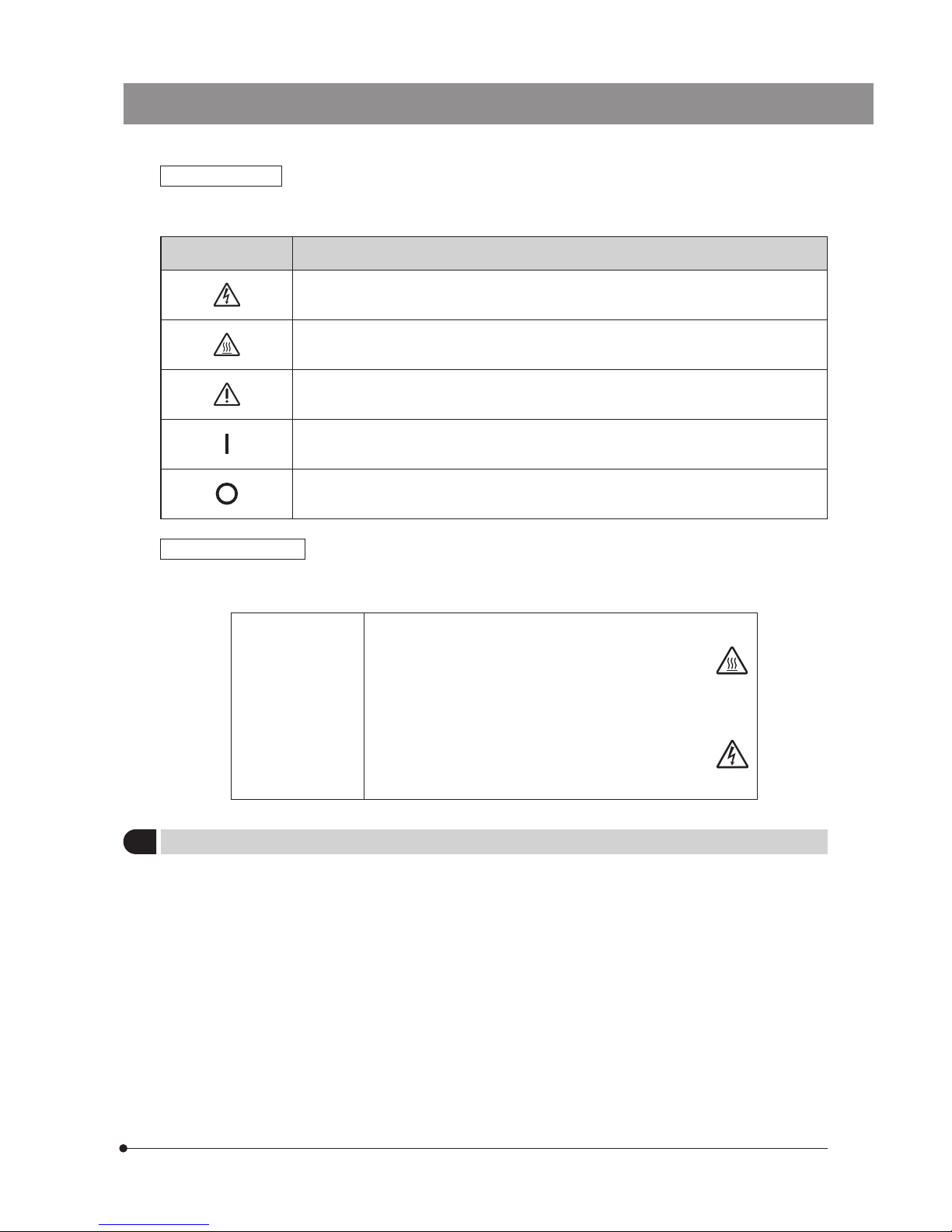
Safety Symbols
The following symbols are found on the microscope. Study the meaning of the symbols and always use the equipment
in the safest possible manner.
Symbol Explanation
Indicates the presence of high voltage (1 kV or more). Take caution to guard against electric
shock.
Indicates that the surface becomes hot, and should not be touched with bare hands.
Indicates a non-specific general hazard. Follow the description given after this symbol or in
instruction manual.
Indicates that the main switch is ON.
Indicates that the main switch is OFF.
Caution indications
Caution indications are placed at parts where special precaution is required when handling and using the System. Always
heed the warnings.
Caution indication
position
· Lamp housing for mercury burner
(U-LH100HG, U-LH100HGAPO)
· Illuminator
(BX3-URA, BX3-RFAS)
· ND filter high voltage]
(BX3-25ND6, BX3-25ND25)
· ND filter slider
(provided with BX3-RFAS)
· Power supply unit
(U-RFL-T)
[Caution against
high temperature]
[Caution against
high voltage]
1 Getting Ready
1. This manual pertains only to the reflected fluorescence system. Before using this system together with the BX3 microscope
and associated options, make sure that you have carefully read and understood their manuals, and understand how the
system should be operated together.
2. The reflected fluorescence system is composed of precision instruments. Handle it with care and avoid subjecting it to
sudden or severe impact.
3. Do not use the system where it is subjected to direct sunlight, high temperature and humidity, dust or vibrations.
4. To allow heat from the unit to dissipate well, reserve clearances of at least 10 cm around the lamp housing and power
supply unit.
5. The power cord can also be used to cut the power supply in case of emergency. To make this possible, the power supply
unit should be installed so that the power cord connector (on the rear of the power supply unit) or the power outlet is
easily accessible for unplugging in case of emergency.
6. Before igniting the burner, make sure that a mercury burner is attached and the cords are connected properly.
7. Avoid turning the lamp on-off repeatedly as this reduces the burner life considerably. The average service life of a mercury
burner is about 300 hours (USH103OL) with operating cycles of 2-hour ON and 30-minute OFF.

3
2 Maintenance and Storage
1. To clean the lenses and other glass components, simply blow dirty away using a commercially available blower and
wipe gently using a piece of cleaning paper (or clean gauze).
If a lens is stained with fingerprints or oil smudges, wipe it gauze slightly moistened with commercially available absolute
alcohol.
Since the absolute alcohol is highly flammable, it must be handled carefully.
Be sure to keep it away from open flames or potential sources of electrical sparks --- for example, electrical
equipment that is being switched on or off.
Also remember to always use it only in a well-ventilated room.
2. With any part of the system other than glass components gets dirty, do not use organic solvents but wipe it with a clean
cloth. If the part is extremely dirty, use a lint-free, soft cloth slightly moistened with a diluted neutral detergent.
3. Do not disassemble or modify the parts of the system unless when instructed to do so in this manual. Otherwise,
malfunction, reduced performance or accident may result.
4. The mercury burner has a service life period of 300 hours (USH-103OL, HBO103W/2). When the hour counter on the power
supply unit indicates this value, set the main switch to “
” (OFF) and wait for more than 10 minutes before replacing
the mercury burner (Page 26). Unlike electric bulbs, the mercury burner seals high-pressure gas inside. If it continues to
be used after the service life has expired, the glass tube may eventually explode due to accumulated distortion.
5. When not using the microscope, be sure set the main switch to “
” (OFF). After confirming that the lamp housing has
cooled down sufficiently, cover the microscope with the dust cover for storage.
6. When disposing of the system, always follow your local regulations and rules. If you have any question, contact
Olympus.
3 Caution
If the system is used in a manner not specified by this manual, the safety of the user may be imperiled. In addition, the
system equipment may also be damaged. Always use the system as outlined in this instruction manual.
The following symbols are used to set off text in this instruction manual.
: Indicates a potentially hazardous situation which, if not avoided, may result in minor
or moderate injury or damage to the equipment or other property. It may also be used
to alert against unsafe practices.
} : Indicates commentary (for ease of operation and maintenance).
CAUTION
CAUTION
4
5
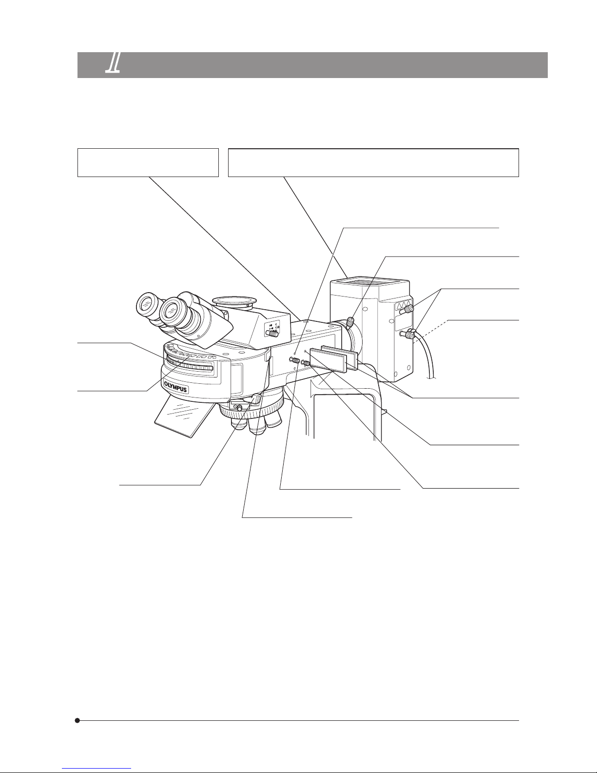
1
NOMENCLATURE
Mirror unit turret
Universal Reflected Illuminator
BX3-URA
Apo Lamp Housing for 100 W Mercury Burner U-LH100HGAPO
Lamp Housing for 100 W Mercury Burner U-LH100HG
Mirror unit inscription
pocket (Page 25)
Shutter knobs
(Provided on both sides.)
(Page 11)
\: Shutter OPEN
{: Shutter CLOSE
Field iris diaphragm knob (Page 11)
Analyzer insertion slot (Page 18)
Field iris diaphragm centering screws (Page 11)
x2 screws.
Collector lens focusing knob (Page 13,14)
Burner centering knobs
(Page 13,14)
Mirror focusing screw
(Page 15)
On the rear of the
lamp housing.
ND filter insertion slots (Page 16)
Provided on both sides.
Aperture iris diaphragm
centering screws (Page 12)
x2 screws
Aperture iris diaphragm knob
(Page 12)
5
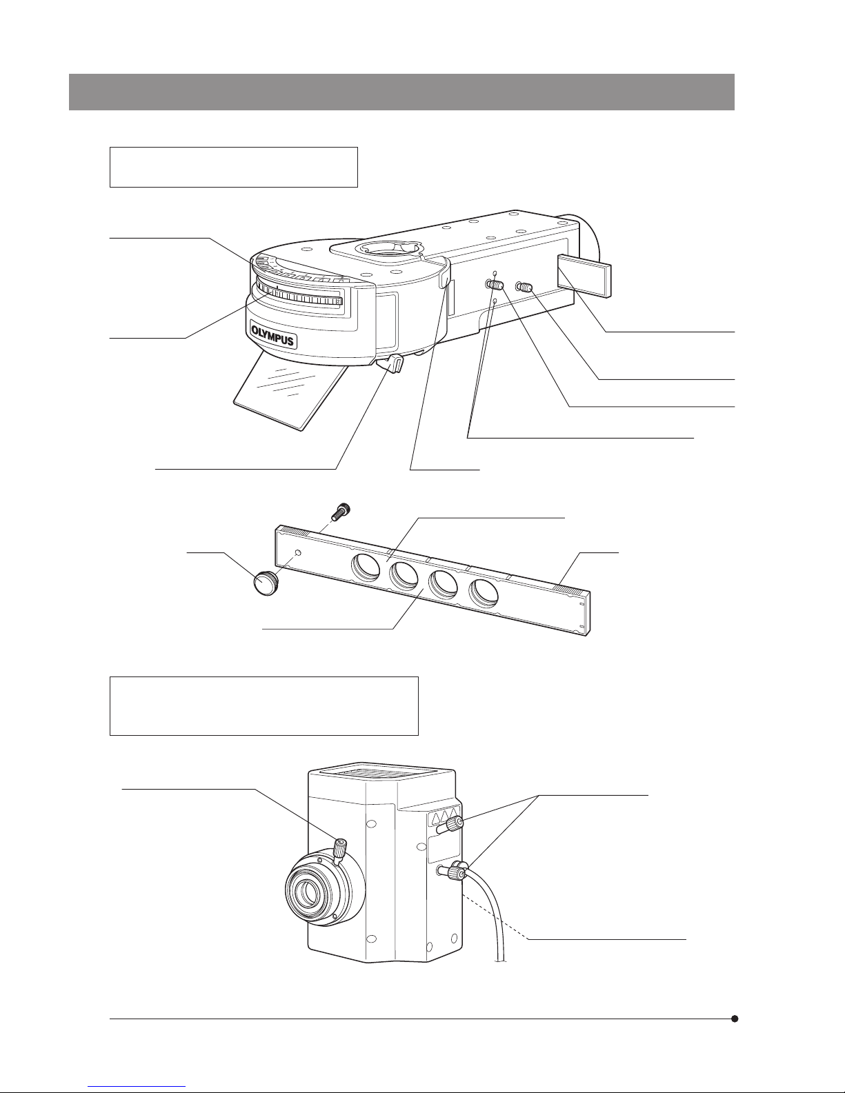
Coded Fluorescence Illuminator
BX3-RFAS
Lamp Housing for 100 W Mercury Burner
U-LH100HGAPO
U-LH100HG
Mirror unit inscription
pockets (Page 25)
Mirror unit turret
Shutter knobs (Provided on both sides.)
(Page 11)
\: Shutter OPEN
{: Shutter CLOSE
ND filter slider insertion slot
(Page 16)
Insertion from right side.
Aperture iris diaphragm knob
(Page 12)
Field iris diaphragm knob (Page 11)
Field iris diaphragm centering screws (Page 11)
Analyzer inlet
Stopper
ND filter slider for BX3-RFAS
Engaged filter name inscription
Stopper
Collector lens focusing knob
Burner centering knobs
Mirror focusing screw
(On the rear of the lamp housing.)
6
7
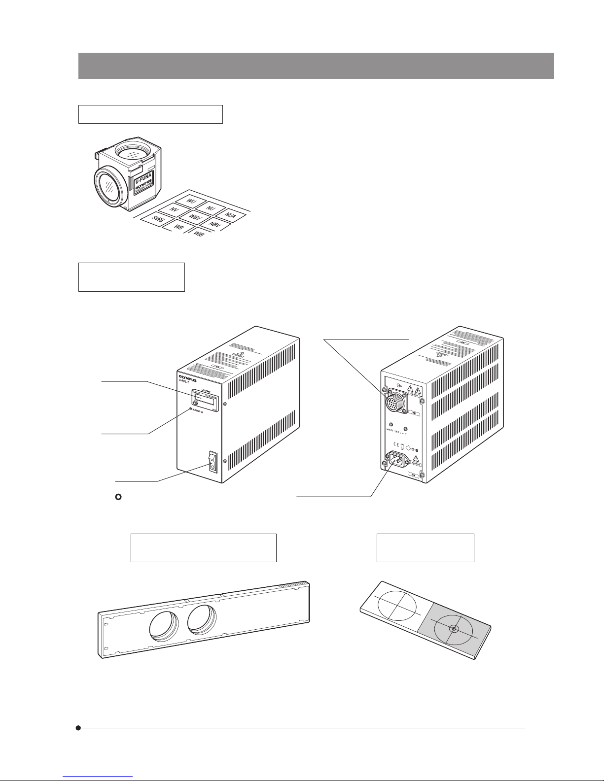
Fluorescence Mirror Units
Indicator sheets
} Up to eight fluorescence mirror units can be mounted on the BX3-URA
or BX3-RFAS.
} It is recommended that you use the U-FF dummy mirror unit (which does
not contain a filter) when making your original fluorescence mirror unit
(page 27).
Blank indicator sheets provided with the illuminator can be used to write
the names of original fluorescence mirror units.
Power Supply Unit
U-RFL-T/U-RX-T
ND Filters
BX3-25ND6, BX3-25ND25
Centering Target
U-CST
} For details, see the instruction manual provided with the U-RFL-T/U-RX-T.
} Use the U-RFL-T when the light source is a mercury burner or use the U-RX-T when the light
source is a xenon burner.
Hour counter
Lamp ON LED
Main switch
I : ON
: OFF
Lamp housing connector
Power cord connector
7
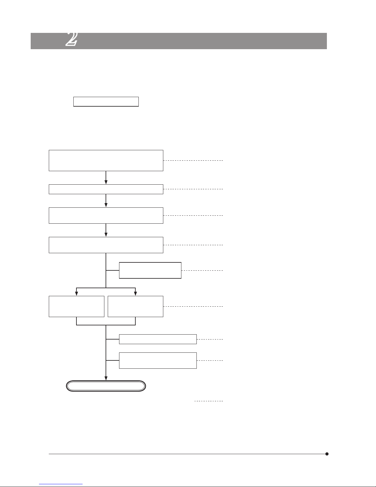
2
REFLECTED FLUORESCENCE OBSERVATION PROCEDURE
Preparation
Set the main switch to “ I ” (ON) and wait for the
lamp brightness to stabilize (5 to 10 minutes
after ignition).
Engage the fluorescence mirror unit matching
the specimen in the light path.
Engage the objective in the light path and focus
on the specimen
Adju st so that t he
entire field is uniform
and brightest.
Adjust the brightness
as required.
Engage an ND filter in the
light path as required.
Place the specimen on the stage.
} If you need simultaneous observation of reflected fluorescence observation with the phase contrast observation or
transmitted light Nomarski Differential Interference Contrast (DIC) observation, please read Chapter 4, “SIMULTANEOUS
FLUORESCENCE OBSERVATION”. (Page 18)
(Controls Used) (Page)
· Attach the fluorescence mirror unit and objective matching the observation method. (Pages 9 to 10)
· Center the mercury burner. (Pages 13 to 15 )
Adjust the field iris diaphragm.
Adjust the aperture iris
diaphragm.
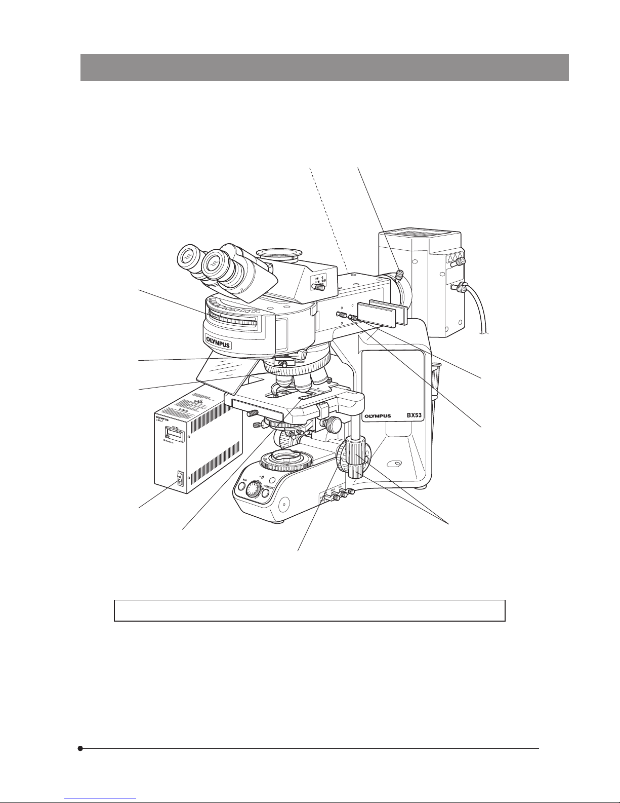
Observation
@Main switch (P.11)
2Slide holder
3X-/Y-axis knobs
4Mirror unit turret
5Revolving nosepiece
6Coarse/fine adjustment knobs
7ND filter (P.16 )
8Collector lens focusing knob (P.13,14)
9Field iris diaphragm knob (P.11)
aAperture iris diaphragm knob (P.12)
bShutter knob (P.11)
BX3-URA BX3-RFAS
} Engage the shutter if you interrupt observation for a short time.
8
9
} Make a photocopy of the observation procedure pages and post it near your microscope.
9
a
7
5
2
8
3
6
b
1
4
 Loading...