

Page 1

Maintenance Manual
for maintenance engineer
Thank you for purchasing the Olympus microscope BX2.
In order to fully utilize its performance and secure optimum condition, please read this manual before maintenance work.
Please also keep it at hand during maintenance as well as for future reference.
All rights reserved, Reproduction in whole or in part without written permission is prohibited.
BX2
Page 2

BX2 MAINTENANCE MANUAL
INTRODUCTION
The purpose of this manual is to satisfy any requirements for maintenance material
that maybe considered as necessary to professionals in the maintenance field, such
as Maintenance engineer in Hospitals.
It is intended to be used as a tool for performing basic maintenance procedures if
needed or when required as per the recommended maintenance schedule.
The sections from this manual only cover procedure pertaining maintenance ’s that
are considered to be easily performed. For more involved maintenance ’s or repairs,
it is recommended that you contact a qualified service engineer from your local
Authorized Olympus dealer.
Maintenance parts, grease, and other items specified in the manual can be ordered
from your Authorized Olympus dealer, and subject to change without notice.
The recommended maintenance schedule is shown below as reference. ( * Necessary item)
Portion Cleaning Optical/mechanical check Maintenance schedule
Optical components
1) Outer surface * Once in a year
Eyepiece, objective, (If dirt is conspicuous or oil
condenser lens, filter, immersion objective is used,
photo eyepiece cleaning should be made after
every use.)
2) Inner part * Once in a year
Prism, built-in filter,
internal lenses, mirror
Appearance * Once in a year
Microscope frame, mechanical (If dirt is conspicuous, cleaning
part should be made after every use.)
Observation tube * Once in a year
Optical adjustment:
1) Optical axis (standard)
2) Left/right optical axis
3) Revolving axis
4) Parfocality
Mechanical part * Once in two to three years
Focusing unit, stage, revolving Mechanical movement:
nosepiece, aperture/field Grease replacement
iris diaphragm Mechanical adjustment
Page 3

BX2 MAINTENANCE MANUAL
CONTENTS
Chapter 1. MAINTENANCE PROCEDURE
1. Maintenance of microscope ....................................................................................................1
2. Guide to maintenance..............................................................................................................2
2-1 Overview of maintenance.................................................................................................... 2
2-2 Cleaning method for the optical components ....................................................................3
3. Preparing for inspection...........................................................................................................6
4. BX2 inspection sheet...............................................................................................................7
Chapter 2. INSPECTION PROCEDURE
1. Checking performance of microscope.................................................................................... 8
2. Checking dirty portion.............................................................................................................. 8
2-1 Image influence caused by dirt on each component......................................................... 8
2-2 How to find dirty portion through observation ...................................................................9
2-3 How to check cleaning condition.......................................................................................10
Chapter 3. REPAIR PROCEDURE
1. Optical adjustment..................................................................................................................11
2. Mechanical adjustment ..........................................................................................................14
2-1 Adjustment method for the tension of X/Y-wire...............................................................14
2-2 Confirmation of X-wire tesion............................................................................................15
2-3 Confirmation of Y-wire tension..........................................................................................15
2-4 Final adjustment.................................................................................................................16
3. Grease replacement for fine focus adjustment knob ass'y.................................................17
4. Electrical adjustment..............................................................................................................18
5. Connecting diagram...............................................................................................................21
Chapter 4. TROUBLESHOOTING
1. Electrical problem...................................................................................................................23
Chapter 5. JIGS AND TOOLS / GREASES AND ADHESIVES
1. List of jigs and tools................................................................................................................24
2. List of greases ........................................................................................................................24
3. List of adhesives.....................................................................................................................24
Chapter 6. MAINTENANCE PARTS
1. List of maintenance parts.......................................................................................................25
Page 4
BX2 MAINTENANCE MANUAL MAINTENANCE PROCEDURE
Chapter 1.
MAINTENANCE PROCEDURE
1. Maintenance of microscope
1) Fundamental handling
a. Read the instruction manual thoroughly, handle the microscope correctly.
b. Be sure to make a usual cleaning, especially after every use of microscope.
c. When handling the microscope, do not expose it to shock, moisture, heat and dust.
d. If the problem occurs, do not treat it in self-judgement.
2) Using and storing conditions
a.The microscope should be used under no vibration.
If it is placed in such environment as vibration, this causes disturbance and fatigue in
observation and affects the photomicrography.
b. It should not be stored in high humidity.
Such condition causes fungus, corrosion on lens and rust on metal part.
Therefore, special caution is exercised if stored in a long period of time.
c. Intense temperature change should be avoided.
Be careful not to place the microscope near window exposed to direct sunlight and air
conditioner. When bringing it into warm room from cold storage location in winter,
condensation occurs on lens and metal part, it causes fungus and rust.
d. It should be kept clean.
The microscope is required to keep away from dust that causes contamination, fungus
on lens and failure of sliding part in the frame.
Be careful not to place it in the environment where the corrodent chemicals such as
hydrogen sulfide, hydrogen fluoride and acid are handled.
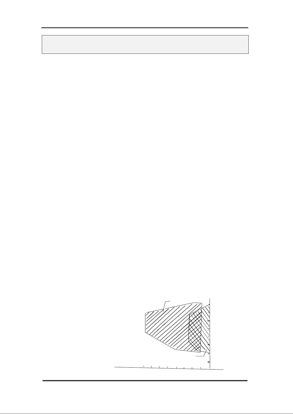
< Reference> fungus: occurrence conditions
Dry blue aspergillus
Temperature
Degree(C)
40
30
Humidity
%
60 70 80
- 1 -
Aspergillus
20
10
90
100
Page 5
BX2 MAINTENANCE MANUAL MAINTENANCE PROCEDURE
2. Guide to maintenance
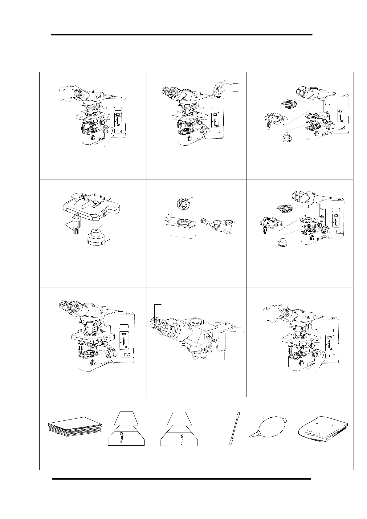
2-1 Overview of maintenance
1) 2) 3)
Set your correct interpupillary distance.
Note any areas suggesting a need for
mechanical and/or optical maintenance
by operating it or observing a specimen.
OLYMPUS
BX51
12
11
10
9
8
6
4
P
PRE-SET
OLYMPUS
BX51
12
11
10
9
8
6
4
P
PRE-SET
Sweep off dust on the outer surfaces
with the soft brush. If there are stains
Remove the revolving nosepiece, stage
and condenser.
on the microscope frame, clean them
with neutral detergent.
4) 5) 6)
OLYMPUS
BX51
12
11
10
9
8
6
4
P
PRE-SET
Plastic part
Plastic part
Wipe off any dirt spots on the surface.
The plastic parts should be cleaned with
neutral detergent.
7)
Polish all plastic components and the
frame with silicon cloth.
Tool required:
OLYMPUS
PRE-SET
BX51
12
11
10
9
8
6
4
P
collector lens
Clean all exposed optics such as
lenses of eyepieces and objectives.
(Only the BX41collector lens should
Mount the removed components to
the microscope frame.
be cleaned with neutral detergent
because it is made of plastic.)
8) 9)
Return the interpupillary distance to
original condition and prepare for
the inspection. (see page 6)
Do a final check following the inspection
sheet in this manual. (See page 7)
OLYMPUS
BX51
12
11
10
9
8
6
4
P
PRE-SET
OLYMPUS
BX51
12
11
10
9
8
6
4
P
PRE-SET
Lens tissue
Neutral detergent
(For plastic part or frame)
Cleaning solution
(For lens or filter etc.)
- 2 -
Cotton swab Blower Silicon cloth
or tweezers etc.
(For finishing)
Page 6
BX2 MAINTENANCE MANUAL MAINTENANCE PROCEDURE
2-2 Cleaning method for the optical components
Required tools:
1) Lens tissue
2) Cotton swab or tweezers etc. 3) Blower 4)Magnifier (Eyepiece is possible to be used by turning
it upside down. Refer to page 10.)
5) Cleaning solution: e.g. Alcohol
Before cleaning: Lightly brush the lens surface or blow with the blower before wiping with tissue.
This removes particles that may scratch the lens surface. (to protect the lens coating)
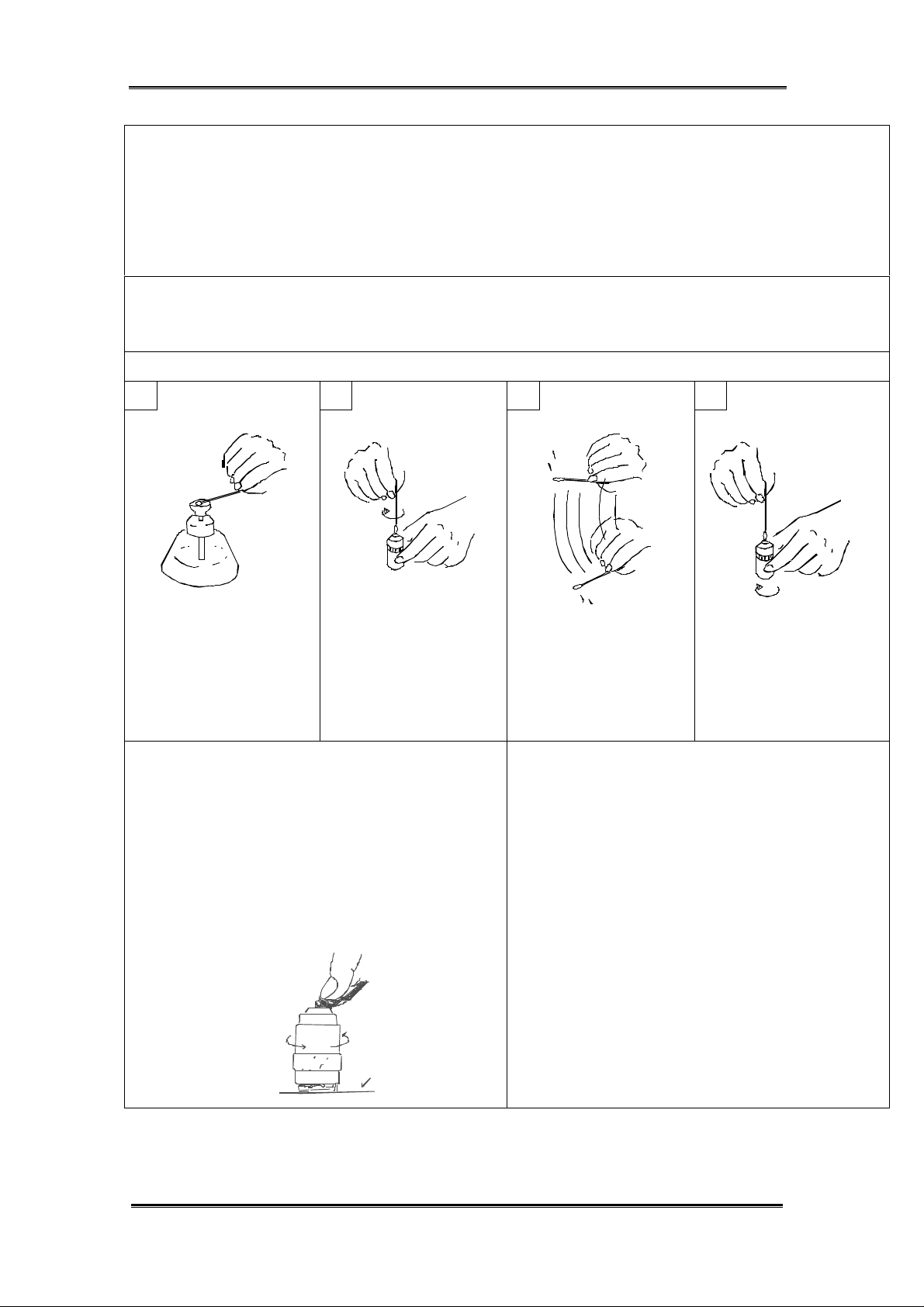
HOW TO CLEAN THE OBJECTIVE LENS
1 2 3 4
Moisten the tip of cotton
swab with cleaning
solution.
With a circular motion,
wipe the top lens
surface with the cotton
swab, to thoroughly
remove any oil or dirt
from the lens.
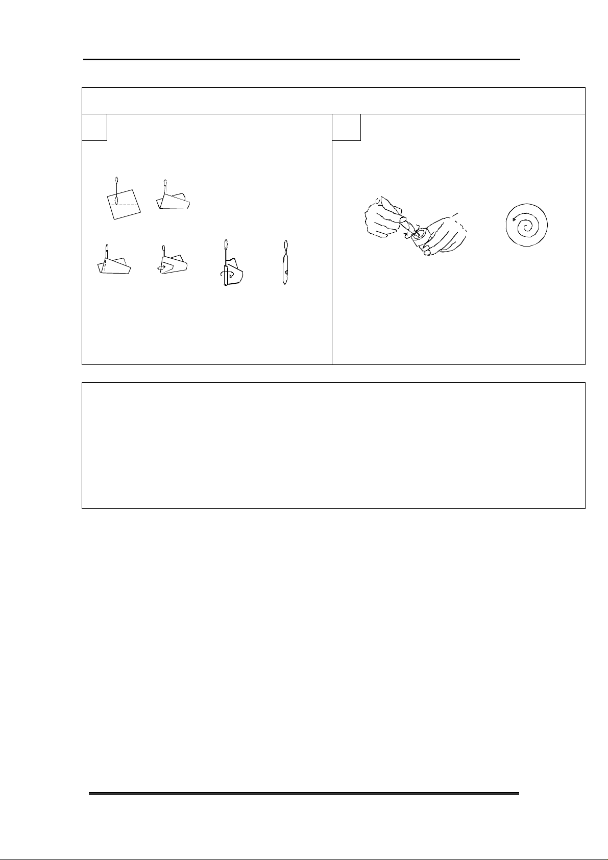
When the lens size is large and difference in
level between the lens and the lens frame is small:
Fold the lens tissue several times and moisten it
with cleaning solution.
After that, apply the folded line edge to the center
of lens, push it with index finger and turn the
objective by the other hand to clean the lens
while moving it from the center towards the
periphery.
Put it on the desk
Dip a new cotton swab
in the cleaning solution
and shake vigorously
to remove any excess
cleaning solution.
wipe the objective lens
from the center towards
the periphery, while
rotating the lens.
Cleaning the immersion objective:
Wipe off the immersion oil while absorbing
it with lens tissue that is not moistened.
After that, clean the lens as the same manner
mentioned on the left.
When the top surface of lens frame is higher
than that of lens and remained dirty potion
on the periphery of lens can not be wiped off,
clean the lens referring the above figures,
1 to 4.
- 3 -
Page 7
BX2 MAINTENANCE MANUAL MAINTENANCE PROCEDURE
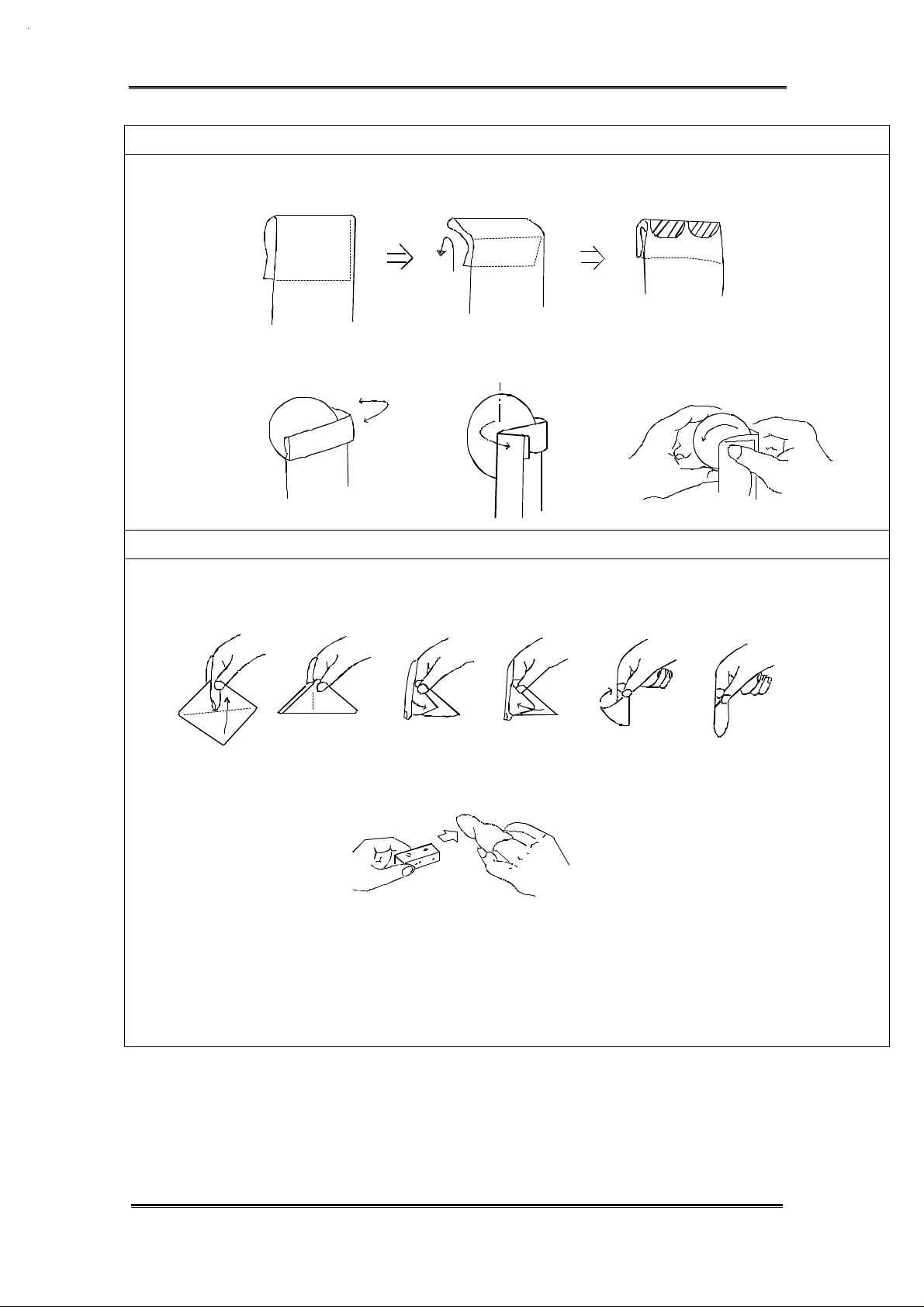
HOW TO CLEAN THE FILTER
Fold the lens tissue into two or three layers and moisten its shaded part with cleaning
solution.
Hold the filter at its edge and fold the lens paper from the lens center to outside as illustrated.
Move the lens tissue gradually to outside while turning the filter by left hand.
HOW TO CLEAN THE PRISM
Hold a sheet of lens tissue between your middle and index fingers, then fold and wrap it around
your index finger. Hold the tissue down with your thumb and moisten it with sufficient cleaning solution.
1)
2) 3)
4)
5)
6)
Wipe the prism surfaces from front to backward at a stroke, applying even pressure.
- 4 -
Page 8
BX2 MAINTENANCE MANUAL MAINTENANCE PROCEDURE
HOW TO CLEAN THE EYEPIECE
1 2
Wrap a sheet of lens tissue
around a cotton swab as
illustrated. If the area to be
cleaned is large, wrap the
Dip the wrapped lens tissue in the
cleaning solution, and wipe the
eyepiece from the center towards
the periphery in a circular motion.
lens tissue looser and
thicker. Otherwise, make a
thin, tight wrap.
.
Important notes:
1) Never rub the lens surface strongly.
2) Do not use the same lens tissue to clean more than one lens .
3) Do not moisten the lens tissue with an excessive amount of cleaning solution.
4) When cleaning with tweezers, be careful not to protrude its tip from the lens tissue.
- 5 -
Page 9
BX2 MAINTENANCE MANUAL MAINTENANCE PROCEDURE
3. Preparing for inspection
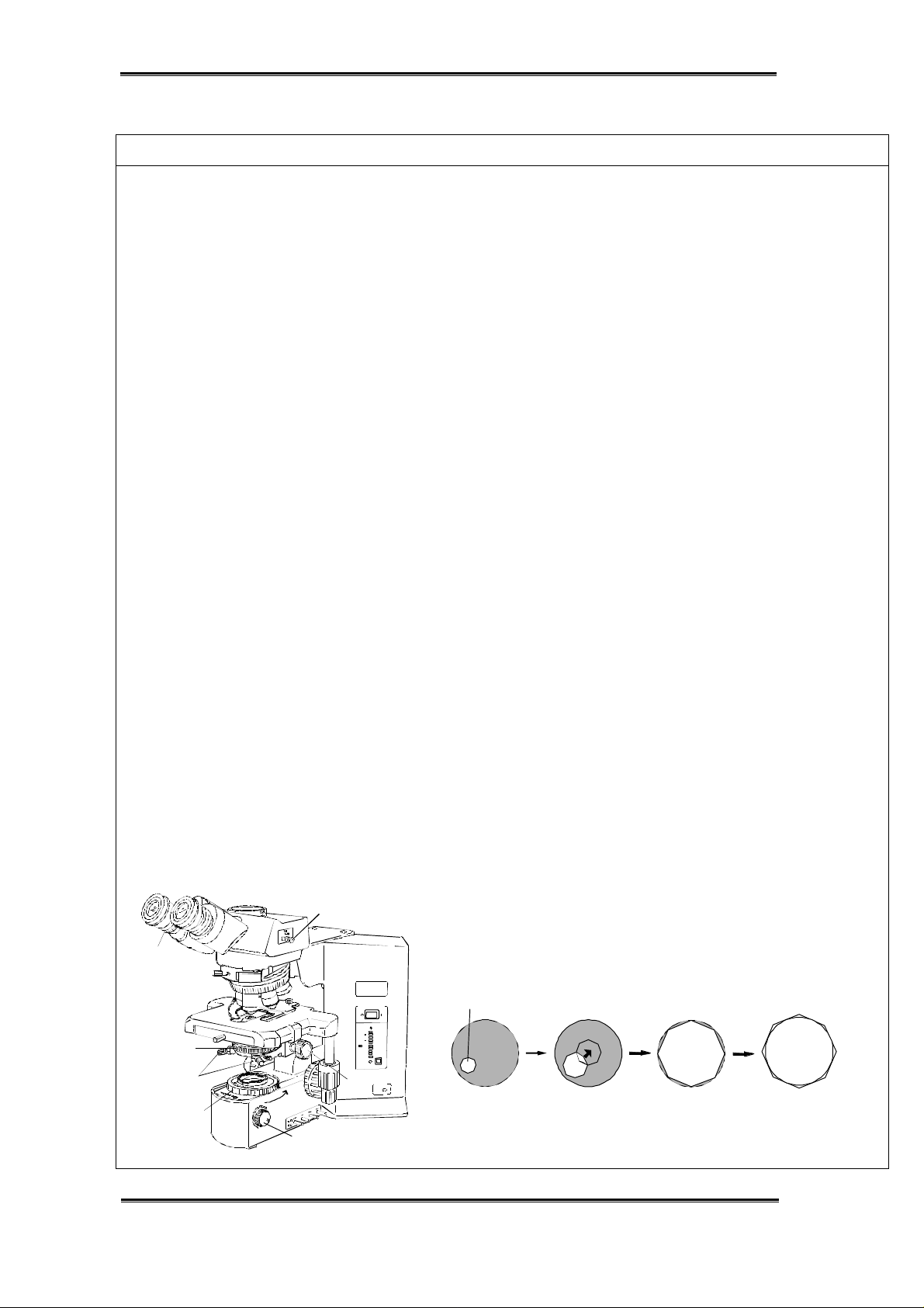
ADJUSTMENT OF KOEHLER ILLUMINATION
1) Set the main switch “A” to “I” (ON) and adjust the brightness by turning the adjustment knob “B” .
2) Set the light path selector knob “C” to the pushed-in position.
(Pushed-in position: Binocular 100%, Middle position: Binocular 20% Photo/TV 80%, Pulled-out position: Photo/TV 100%)
3) Place a specimen on the stage.
4) Engage the 10X objective in the light path.
5) Turn the condenser height adjustment knob “D” to raise the condenser to its upper limit.
( When using the U-SC3 swing-out condenser, move the top lens into the light path.)
6) Looking through the eyepiece in the right sleeve without the diopter adjustment ring, turn the
coarse and fine focus adjustment knobs to bring the specimen into focus.
7) Looking through the eyepiece in the left sleeve with the diopter adjustment ring, turn only the
diopter adjustment ring “E” to focus on the specimen.
(At this time, adjust the interpupillary distance so that the binocular visions on the left and
right fields of view coincide completely.)
8) Turn the field iris diaphragm ring “F” in the direction of the arrow so that the iris diaphragm image
comes inside the field of view.
9) Manipulate the condenser height adjustment knob “D” to focus on the iris diaphragm image. (See Fig.1)
10) Turn the two condenser centering screws “G” to move the iris diaphragm image to the center
of field of view. (See Fig. 2)
11) Gradually open the field iris diaphragm. The condenser is properly centered if the iris diaphragm
image is centered and inscribed in the field of view. (See Fig.3)
(During actual use, open the field iris diaphragm slightly until its image circumscribes the field
of view. See Fig.4)
Reference: Since the contrast of microscope specimens is ordinary low, setting the condenser
aperture iris diaphragm to between 70% and 80% of the N.A. of the objective in use
is usually recommended. If necessary, adjust the ratio by removing the eyepiece
and looking into the eyepiece sleeve while adjusting the aperture iris diaphragm ring “H”.
C
E
OL YMPUS
BX51
12
11
10
9
8
H
G
6
4
P
PRE-SET
D
F
B
A
Field iris
diaphragm image
Fig.1
Fig.2
Fig.3
Fig.4
- 6 -
Page 10

BX2 MAINTENANCE MANUAL MAINTENANCE PROCEDURE
4. BX2 inspection sheet
MODEL : CHECK DATE :
S/N : CHECKING BY :
CHECK POINT
CHECK CONTENTS
RESULT REF. PAGE
1. Electrical unit
1) When the power switch is turned on, the lamp is lit
and the brightness can be varied by adjustment knob.
2) When the light preset switch is set ON, the previously
set voltage can obtained regardless of brightness
adjustment knob position.
3) The voltage of light preset switch can adjusted in a
prescribed range.
2. Coarse/fine focus
adjustment knob
1) The coarse/fine focus adjustment knob is smoothly
moved without tightness or unevenness.
2) The tension of coarse focus adjustment knob can be
adjusted by the adjustment ring.
3) The coarse upper limit lock is effective.
3. Stage
1) The stage is fixed by the clamping screw.
2) The stage can be rotated clockwise or
counterclockwise while holding the clamping screw
after the screw is loosened.
3) The stage should not fall spontaneously.
4) A specimen is held securely by the specimen holder.
5) The X/Y movement is smooth without unevenness,
backlash or slipping.
4. Observation tube
1) The interpupillary distance adjustment can be
operated smoothly in working range.
2) When changing the interpupillary distance,
the displacement of optical axis is not apparent.
3) The diopter adjustment ring is moved smoothly
in working range.
4) The optical axis of left side coincides with that of right
side.
5) The light path selector knob is moved smoothly.
6)The tilting angle is easily adjusted and its angle
is stable. (U-TBI / U-ETBI only)
7) When changing the tilting angle, the optical axis
displacement is not apparent. (U-TBI / U-ETBI only)
5. Revolving
nosepiece
6. Condenser
1) The revolving nosepiece can be rotated smoothly
and stops at the click position.
1) The vertical movement of condenser is smooth.
2) The centering of field iris diaphragm can be adjusted in
a movable range with the condenser centering knobs.
7. Illumination 1) The field/aperture iris diaphragm ring is moved normally.
8. Visibility
(Observation)
1) Observation image is normal.
Without flares /ghosts / vignetting /uneven illumination
2) When photographed, there is no unevenness or
shading on the film surface.
3) Dust and dirt are not noticeable in observation or
photomicrography.
Remarks:
OK / NO
OK / NO
OK / NO
OK / NO
OK / NO
OK / NO
OK / NO
OK / NO
OK / NO
OK / NO
OK / NO
OK / NO
OK / NO
OK / NO
OK / NO
OK / NO
OK / NO
OK / NO
OK / NO
OK / NO
OK / NO
OK / NO
OK / NO
OK / NO
OK / NO
18, 19, 20
17
14, 15, 16
11, 12, 13
8, 9
- 7 -
Page 11

BX2 MAINTENANCE MANUAL INSPECTION PROCEDURE
Chapter 2.
INSPECTION PROCEDURE
1. Checking performance of microscope Using the BX2 maintenance sheet (P.7), check the electrical unit, mechanical and
optical performance.
2. Checking dirty portion
2-1 Image influence caused by dirt on each component The following figure shows the influence of image on each optical component if stains or dust is adhered to that portion. In general, the microscope image or photographing is largely affected by dirt adhered on the nearer portion to a specimen and image surfaces. Therefore, the optical components should be kept clean and dust-free.
B
Photo eyepiece
C
Prism
B
Eyepiece
D
objective
A
Specimen
12
B
Condenser lens
C
Collector lens
C
Filter
C
Built-in filters
•E
11
•E
10
9
8
6
4
p
A: Dirt is clearly seen.
B: Blurred contours of dirt is seen.
C: Dirt is seen when the aperture iris diaphragm is stopped down.
D: Dirt is not directly seen, but contrast of image deteriorates.
- 8 -
Page 12

BX2 MAINTENANCE MANUAL INSPECTION PROCEDURE
2-2 How to find dirty portion through observation
1) Stop down the aperture iris diaphragm.
(When the aperture iris diaphragm is stopped down, it facilitates finding the dirt
particles because the depth of focus increases and the dirt position bring into
focus. However, very small dirt particle may not be found in this method.)
2) Observe a specimen through the eyepiece.
If dirt is seen by observing it, look for the portion where stains or dust is adhered
by moving the following components as well as a specimen.
For TV camera, check it by method shown below.
OLYMPUS
Photo eyepiece
Check it by rotating
the photo eyepiece.
(The dust particles will be
focused on the film plane.)
NFK5XLD
125
TV camera
Dust particles appearing on
the monitor screen: if the particles
move only when the specimen or
condenser is moved, clean the
specimen and/or condenser.
If they do not moved when the TV
camera is rotated, clean the
camera tip.
Eyepiece
Check it by rotating the eyepiece.
(Wipe carefully and gently so as
not to damage the lens coating.)
Objective
Dirt is not directly seen, but
dirt and dust particles affect
the microscope image.
Condenser
Check it by loosening the
fixing screw and moving
the condenser forward or
backward.
Filter/Collector lens
Check it by rotating the filter.
(Dust and dirt particles here
have minimal effect on the
image. However, the overall
appearance requires frequent
cleaning. Wipe evenly since
this is a wide surface area.)
OLYMPUS
BX51
PRE-SET
Built-in Filters
Check it by pulling in and out
the knob of filter.
Difficult to clean. please consult
your Authorized Olympus dealer.
12
11
10
9
8
6
4
P
Mirror for Large format attachment
Dust and durt particles here affect
pictures. Difficult to clean without
damaging the mirror surface.
Please contact your Authorized Olympus
dealer.
Note: If dirt particles do not move by moving the above components, it is assumed that
the lens and filter inside the microscope is contaminated.
In this case, please contact your Authorized Olympus dealer.
- 9 -
Page 13

BX2 MAINTENANCE MANUAL INSPECTION PROCEDURE
2-3 How to check cleaning condition
1) When a large lens is checked, look at the lens while putting it toward bright side or
breathe on the lens and observe the condition that the haze on the whole surface
of the lens disappears evenly.
light
Dust becomes conspicuous when If there is a dirty part or a remained
looking at it with the lens inclination part that is not cleaned completely,
changed. the haze of this part will disappear
slower than that of the other part.
2) For a small lens such as top lens of objective, check it by magnifier.
An eyepiece can be substituted for
magnifier by turning the eyepiece
upside down.
- 10 -
Page 14

BX2 MAINTENANCE MANUAL REPAIR PROCEDURE
Chapter 3.
REPAIR PROCEDURE
1. Optical adjustment
PREPARATION
If the left/right optical axis is remarkably displaced at
checking, perform the following adjustment.
CROSS WH10X
Align the specimen center with the cross center of the
WH10X eyepiece by turning the control knob of the stage.
Adjusting the left/right optical axis
*Insert the cross eyepiece
into the right sleeve.
Objective 4X-10X
specimen
whose center is
identified
(Concentric circles etc.)
*Adjust the interpupillary
distance to about 62mm
(See the illustration).
70
60
50
position of
approx. 62mm
Cross center of
cross WH10X
Before adjustment
specimen center
After adjustment
Control knob
- 11 -
Page 15

BX2 MAINTENANCE MANUAL REPAIR PROCEDURE
ADJUSTMENT THE LEFT/RIGHT OPTICAL AXIS
(1) Moving the cross eyepiece to the left sleeve.
Work Image seen through the cross eyepiece
Move the cross eyepiece to the left sleeve. If the optical axis between left and right sleeve
is deviated, the center of the specimen and the
cross center of eyepiece are also deviated.
70
60
50
(2) Aligning the cross center of eyepiece with the specimen center.
Work Image seen through the cross eyepiece
1. Loosen the two screws slightly which
Image at first
secure the left sleeve.
70
60
50
2. Align the center of eyepiece with the
The center are aligned.
specimen center while observing through
the cross WH10X.
(Change the left sleeve position by
hand.)
70
60
50
- 12 -
Page 16

BX2 MAINTENANCE MANUAL REPAIR PROCEDURE
3. Firmly tighten the screws which secure the
left sleeve.
70
60
50
Image at the end of adjustment
- 13 -
Page 17

BX2 MAINTENANCE MANUAL REPAIR PROCEDURE
2. Mechanical adjustment
2-1 Adjustment metod for the tension of X/Y-wire
If a specimen image is moved when the stage is brought into the desired position of
specimen, it is necessary to adjust the wire tension of stage.
( In case where the stage movement is heavy due to hardening of grease, please contact
your Authorized Olympus dealer because disassembling the stage is required for
grease replacement.)
Adjustment method for X/Y-wire
(Refer to the figure shown below.)
1) Remove the stage from the frame.
2) Turn over the stage and loosen the two fixing screws (CUKSK3X6SA) securing the
holder.
3) Turn the adjustment screw (CSK3X5SA) clockwise or counterclockwise to adjust
the wire tension (See page 15). Tighten the two fixing screws (CUKSK3X6SA).
4) Mount the stage to the frame, set the microscope at observation state and check
that the image is brought into the desired position without backlash (within 2
microns at the lowest torque of X/Y stage knob: see page 16).
5) Repeat the procedure 1) to 4) until the condition is satisfied (both X and Y wires).
6) After completing the adjustment , apply adhesive (OT1131) to each three screws.
Cross-section view
*Adjustment screw
for X-wire
(CSK3X5SA)
*When this screw is turned clockwise(inserting direction),
the wire tension increases. The tension decreases by
turning it counterclockwise.
Holder
(A006)
OLYMPUS
U-SVLB-4
9 E 0 0 0 0 2
JAPAN
Fixing screw
(CUKSK3X6SA
)
Adjustment screw
for Y-wire
(CSK3X5SA)
Holder
(A007)
Bottom view
- 14 -
Kob ass'y
(A008)
Fixing screw
(CUKSK3X6SA)
Adjustment method of Y-wire is
the same as X-wire.
Page 18

BX2 MAINTENANCE MANUAL REPAIR PROCEDURE
2-2 Confirmation of X-wire tension
*1
A
1) Move the X-guide “A” to the center of
the upper stage “B” , press”C” of the
X-wire using the fan-shaped tension
C
D
B
2-3 Confirmation of Y-wire tension
B
F
A
gauge(OT3232). If the tension does not
meet the standard, adjust the tension
so as to be within the standard when
the X-wire comes into contact with “D”
wall by means of the CSK3X5SA(*1)
screw.
Tension standard
1) Press the upper part of Y-wire “A” indicated
by the the arrow with the fan-shaped
tension gauge. If the tension does not meet
the standard, adjust the CSK3X5SA(*1)
scew so that the tension is within the
standard when the Y-wire comes into
0.25-0.3N(25-30gf)
contact with “F” part of the lower stage “B”
when seen from the above.
Tension standard
*1
Note: If the wire is too tight, image backlash may occur.
If the tension is below the standard value, slip may occur between the knob
and the wire deteriorating the image movement.
0.88-0.98N(90-100gf)
- 15 -
Page 19

BX2 MAINTENANCE MANUAL REPAIR PROCEDURE
2-4 Final adjustment
(1) Image backlash adjustment
1) Set the stage on the microscope frame.
Under observation state (with 100X objective),
A
check image backlash at the lowest knob
torque. If it is over 2 microns, conduct adjustment.
(The knob rotation torque is measured by
turning the knob with a sting or some other
suitable item adhered to it, using tension
gauge.)
*2
2) When adjusting Y-movement, loosen the two
screws(*1) and turn the Y-knob “A” to bring
backlash within 2 microns. Turn the stopper
ring “B” to come into contact with knob “A”,
C
and fix the stopper ring using the two
(A009)
AWU2X2SA(*1) screws.
3) When adjusting X-movement, remove the
X-knob “C” after loosing the two AWU3X3SA
*1
B
D
Tension gauge: OT3326
screws.
Loosen the screw(*2). Turn the F-ring “D” to
bring image backlash within 2 microns, and fix
the F-ring using the HU1.7X2SA(*2) screw.
At this time, make sure that the final knob
torque at the lowest is within the following
standard for both X and Y.
Knob torque at the lowest:
X: 0.25 -0.35N (25 - 35gf)
Y: 0.39 - 0.59N (40 - 60gf)
- 16 -
Page 20

BX2 MAINTENANCE MANUAL REPAIR PROCEDURE
3. Grease replacement for fine focus adjustment knob ass’y
If the adjustment knob is not turned smoothly, replace grease on the shaft and gear of fine
adjustment ass’y in the following procedure.
(In case where the coarse adjustment knob ass’y is not turned evenly, please contact your
Authorized Olympus dealer because it is necessary to disassemble the coarse adjustment
knob ass’y and/or guide unit.)
1) Remove the screw (AB4X10SA *1) and take off the knob.
2) Hold the fine focus adjustment knob (left) and turn the fine focus adjustment knob (right)
to remove them. (At this time, the fine focus adjustment knob ass’y (right ) is removed
as an assembly of shaft, gear and fine focus adjustment knob. )
3) Remove grease(OT2008) on the shaft by cleaning solution and replace it.
For the gear, apply grease(OT2012) on it.
4) Assemble the components in reverse order of disassembly.
(A005)
Cap
Fine focus adjustment knob (Left)
(A004)
Fine focus adjustment knob ass'y (right)
(A002)
Apply grease (OT2008)
to the shaft.
Adhesive(OT1087) has been
applied to the screw thread
of shaft on the right side.
Apply grease (OT2012) to
the gear.
(A001)
Fine focus adjustment knob
(A003)
Knob
*1
- 17 -
Page 21

BX2 MAINTENANCE MANUAL REPAIR PROCEDURE
4. Electrical adjustment
The following shows the voltage adjustment when the rheostat ass’y is replaced.
(1) Replacement of rheostat ass’y
1) Remove the bottom cover “A” of
microscope frame.
2) Loosen the screw of knob “B” and
disassemble the parts in order of “B” to
to “E”.
Note: Remove the rheostat ass’y
from inside of base.
3) Disconnect the connector of rheostat
ass’y.
4) Reassemble them in reverse order.
A
Rheostat ass'y
(A011/A012)
E
D
C
B
Knob
(A010)
(2) Setup for adjustment (BX51/52)
1) Remove the back panel of microscope
frame.
Connect the lamp housing.
(U-LH100-3/U-LH100)
Power board
Screw: CUK3X6SA 8 pcs.
2) Remove the control board . (Refer to the
next page.)
CN51
VR52
Screw: CUTB3X6SA 4 pcs.
3) Prepare for adjustment as shown in the
Lamp voltage
output terminal
12.2
Digital multimeter(RMS)
- 18 -
left figure.
Page 22

BX2 MAINTENANCE MANUAL REPAIR PROCEDURE
(3) Adjustment procedure (BX51/52)
1) Turn on the power, and then turn the
knob “B” (P.18) to the maximum level.
2) In step 1), turn the trimmer VR52 (P.18)
on the power board to adjust the lamp
output voltage to 12.2V, using the digital
This LED
should be lit.
Control board
Connect it to the
connector CN51 on
power board.
Connect it to
the relay
board. (only
BX51/52TRF)
multimeter.
Standard DC12.2V+/-0.1V
VR103
3) Turn on the light preset switch.
4) Set the light preset voltage to 9V by
VR101
turning the VR101.
Standard DC9V+/-0.1V
Light preset switch
5) In step 4), turn the trimmer VR103 so that
Connect it to
rheostat ass'y.
(A012)
nineth LED from the bottom will light.
6) Apply solvent-based adhesive(OT1026) to
several points around all trimmers except
(4) Setup for adjustment (BX41/45)
Power board
CN21
Lamp voltage
output terminal
Install U-LS30-4 on the frame
5.9
VR101 to avoid turning the trimmers.
1) Remove the back panel of microscope
frame.
Screw: CUKSK3X8SA 7 pcs.
Note: In case of disassembly from the frame,
after removing the screws, separate the
back panel from wrench holder and take
off the panel while shifting it down.
2) Remove the control board . (Refer to the
next page.)
Screw: CUTB3X6SA 2 pcs.
3) Prepare for adjustment as shown in the
left figure.
Digital multimeter (RMS type)
- 19 -
Page 23

BX2 MAINTENANCE MANUAL REPAIR PROCEDURE
(5) Adjustment procedure (BX41)
Connect to the
connector CN21 on
power board.
1) Turn on the power, and then turn the
knob “B” (P.18) to the maximum level.
2) While turning the trimmer (VR203”A”) on
the control board, adjust the lamp output
voltage to 5.9V using the digital multimeter.
VR203
A
Standard DC5.9V+/-0.1V
3) Turn on the light preset switch.
4) Set the light preset voltage to 4V by
Light preset
switch
VR202
B
Control board
turning the the trimmer (VR202”B”).
Standard
DC4V+/-0.1V
5) For prevention of turning, apply
solvent-based adhesive(OT1026) on
Connect to the
rheostat ass'y (A011).
the one spot of trimmer(VR203).
(6) Adjustment procedure(BX45)
Connect to the connector
CN21 on power board.
1) Turn on the power, and then turn the
knob “B” (P.18) to the maximum level.
2) While turning the trimmer (VR203”A”) on
Light preset switch
the control board, adjust the lamp output
voltage to 5.9V using the digital multimeter.
VR203
A
Standard DC5.9V+/-0.1V
3) Turn on the light preset switch.
4) Set the light preset voltage to 4V by turning
Connect to the
rheostat ass'y (A011).
5) For prevention of turning, apply
VR202
Control
board
B
the trimmer (VR202”B”).
Standard DC4V+/-0.1V
solvent-based adhesive(OT1026) on the
- 20 -
spot of trimmer (VR203).
Page 24

BX2 MAINTENANCE MANUAL REPAIR PROCEDURE
5. Connecting diagram
BX51TF/BX52TF
U005
Power Board
INPUT
100-120/
220-240VAC
50/60Hz
U002
L
E
N
U001
L
Fuse Board
N
X001
121
2
U003 S001
4
3
1
21212
U004
CN1
CN51
1 5
CN52
CN54
U006
2 1
3 4
12V
100W
Halogen Lamp
BX51TRF/BX52TRF
U002
INPUT
L
100/120V
220/240VAC
50/60Hz
E
N
U001
L
Fuse Board
N
X001
1212314
S001
U003
1
CN101
5
Displa y Board
X002- X006
X007- X012
U005
12V
2
3 4
2 1
3
100W
Halogen Lamp
1
4
12V
100W
Halogen Lamp
U008
U006 U007
CN104 CN105
1
Rela y Board
CN101
2
CN106
X002- X006
X007- X012
U004
CN1
121
Pow
2
2
er Board
1 5
1
CN101
Displa
CN51
y Board
CN102
5
CN52
CN53
CN54
1
2
- 21 -
Page 25

BX2 MAINTENANCE MANUAL REPAIR PROCEDURE
BX41TF/BX45TF
U005
Power Board
INPUT
100-120/
220-240VAC
50/60Hz
U002
L
E
N
U001
L
Fuse Board
N
1212314
S001
U003
U004
CN1
121
2
2
CN21
1 7
7 1
CN201
Display Board
X001- X005
X006- -X011
CN20
U006
1
1
2
2
6V
30W
Halogen Lamp
- 22 -
Page 26

BX2 MAINTENANCE MANUAL TROUBLESHOOTING
Chapter 4. TROUBLESHOOTING
1. Electrical problem
BX51/52
Problem Cause Remedy
Bulb is nearly burned out. Replace bulb.a) Bulb intermittently lights and goes
out.
A connector is not properly connected. Check all connectors.
b) Bulb burns out almost immediately. Wrong type of bulb is being used. Use correct bulb type.
c) Brightness does not change when
Light preset switch is set ON. Preset switch to OFF.
you turn light intensity adjustment
knob.
d) All voltage indicator LEDs light and
voltage cannot be varied with light
intensity adjustment knob.
e) Lamp voltage cannot be varied
with light intensity adjustment knob.
Bulb is not installed. Install bulb.
Bulb is burned out. Replace bulb.
Lamp socket is not connected. Connect lamp socket
correctly.
Bulb is burned out. Replace bulb.
BX41/45
Problem Cause Remedy
a) Bulb intermittently lights and goes
out.
b) Bulb burns out almost immediately. Wrong type of bulb is being used. Use correct bulb type.
c) Brightness does not change when
Bulb is nearly burned out. Replace bulb.
A connector is not properly connected. Check all connectors.
Light preset switch is set ON. Preset switch to OFF.
you turn light intensity adjustment
knob.
Bulb is not installed. Install bulb.
Bulb is burned out. Replace bulb.
Lamp socket is not connected. Connect lamp socket
d) Voltage indicator LED does not light
or bulb does not light.
The voltage selector switch is set to the
wrong position.
- 23 -
correctly.
Set the switch to position
matching your local line
voltage(100-120V or
220-240V).
Page 27

BX2 MAINTENANCE MANUAL JIGS AND TOOLS/GREASES AND ADHESIVES
Chapter 5. JIGS AND TOOLS / GREASES AND ADHESIVES
1. List of jigs and tools
No. Description Ref. page
OT3232 Fan-shaped tension gauge (2N) 15
OT3326 Tension gauge (1N) 16
Cleaning tools 2, 3
3822800 Cross WH10X 11, 12, 13
Digital multimeter 18, 19, 20
Philips screwdriver 12, 13 14
Allen wrench 16, 17
Precision screwdriver 19, 20
Dust cover
2. List of greases
No. Description Ref. page
OT2008 Grease (medium) 17
OT2012 Mo grease 17
3. List of adhesives
No. Description Ref. page
OT1026 Solvent-based adhesive 19, 20
OT1087 Anaerobic adhesive
(used when fine focus adjustment knob ass’y is
disassembled)
OT1131 shellac 14
17
- 24 -
Page 28

BX2 MAINTENANCE MANUAL MAINTENANCE PARTS
Chapter 6.
MAINTENANCE PARTS
1. List of maintenance parts
Index No. Order No. Description Ref. page
AX9870 BX41RF Instruction manual
AX9853 BX41TF Instruction manual
AX9857 BX45TF Instruction manual
AX9869 BX51RF Instruction manual
AX9855 BX51/52 Instruction manual
A001 AB872600 Gear
A002 AD490000 Fine focus shaft
A003 AD490400 Fine focus adjustment knob (right)
A004 AD490500 Fine focus adjustment knob (left)
A005 AD490800 Cap
A006 AC740900 Holder (for X-wire)
A007 AD411200 Holder (for Y-wire)
A008 AQ212500 Knob ass’y (for clamping stage)
A009 AD604200 X-knob 16
A010 AD495600 Knob
A011 DZ268000 Rheostat ass’y (for BX41/45)
A012 DZ268100 Rheostat ass’y (for BX51/52)
12V100W halogen bulb (for BX51/52)
6V30W halogen bulb(for BX41/45)
17
14
18, 19, 20
21, 22, 23
- 25 -
Page 29

OLYMPUS OPTICAL CO., LTD
1-22-2, Nishi shinjuku shinjuku-ku, Tokyo, Japan
Issued by Life Science Marketing Dept.
Printed in Japan 2001 01 SK9212
 Loading...