

Olympus BondMaster 600 User Manual

BondMaster 600
Composite Bond Tester
User’s Manual
DMTA-10045-01EN — Rev. E
August 2016
This instruction manual contains essential information on how to use this Olympus product safely and effectively.
Before using this product, thoroughly review this instruction manual. Use the product as instructed.
Keep this instruction manual in a safe, accessible location.

Olympus Scientific Solutions Americas, 48 Woerd Avenue, Waltham, MA 02453, USA
Copyright © 2014, 2015, 2016 by Olympus. All rights reserved. No part of this publication
may be reproduced, translated, or distributed without the express written permission of
Olympus.
This document was prepared with particular attention to usage to ensure the accuracy of the
information contained therein, and corresponds to the version of the product manufactured
prior to the date appearing on the title page. There could, however, be some differences
between the manual and the product if the product was modified thereafter.
The information contained in this document is subject to change without notice.
Part number: DMTA-10045-01EN
Rev. E
August 2016
Printed in the United States of America
SD, miniSD, and microSD Logos are trademarks of SD-3D, LLC.
All brands are trademarks or registered trademarks of their respective owners and third
party entities.

DMTA-10045-01EN, Rev. E, August 2016
Table of Contents
List of Abbreviations ....................................................................................... ix
Labels and Symbols ........................................................................................... 1
Important Information — Please Read Before Use ..................................... 5
Intended Use .......................................................................................................................... 5
Instruction Manual ................................................................................................................ 5
Instrument Compatibility ..................................................................................................... 6
Repair and Modification ....................................................................................................... 6
Safety Symbols ....................................................................................................................... 7
Safety Signal Words ............................................................................................................... 7
Note Signal Words ................................................................................................................. 8
Safety ....................................................................................................................................... 9
Warnings ................................................................................................................................. 9
Battery Precautions .............................................................................................................. 10
Hearing Protection .............................................................................................................. 11
Equipment Disposal ............................................................................................................ 11
CE (European Community) ............................................................................................... 12
WEEE Directive .................................................................................................................... 12
China RoHS .......................................................................................................................... 12
Korea Communications Commission (KCC) ................................................................... 13
EMC Directive Compliance ................................................................................................ 14
FCC (USA) Compliance ...................................................................................................... 14
ICES-001 (Canada) Compliance ........................................................................................ 14
Warranty Information ......................................................................................................... 15
Technical Support ................................................................................................................ 15
Introduction ...................................................................................................... 17
Table of Contents iii

DMTA-10045-01EN, Rev. E, August 2016
1. Package Contents ....................................................................................... 19
1.1 Unpacking .................................................................................................................. 19
1.2 Initial Inspection ........................................................................................................ 19
1.3 Contents of the Case ................................................................................................. 20
2. Overview of the BondMaster 600 ............................................................ 23
2.1 Operating Principle and Test Techniques .............................................................. 23
2.2 Connectors ................................................................................................................. 25
2.3 Power Requirements ................................................................................................. 28
2.3.1 Charger/Adaptor ............................................................................................ 29
2.3.2 Battery Compartment .................................................................................... 32
2.3.3 Lithium-Ion Battery ....................................................................................... 34
2.3.4 Alkaline Batteries ........................................................................................... 35
2.4 MicroSD Card Installation ....................................................................................... 36
2.5 BondMaster 600 Hardware Features ...................................................................... 37
2.5.1 Hardware Overview ...................................................................................... 38
2.5.1.1 Front Panel and SmartKnob ............................................................... 39
2.5.1.2 Keypad .................................................................................................. 40
2.5.2 Connectors ....................................................................................................... 45
2.5.2.1 PROBE Connector ............................................................................... 45
2.5.2.2 Input/Output and VGA OUT Connectors ....................................... 46
2.5.2.3 MicroSD and USB Port ....................................................................... 47
2.5.3 Various Hardware Features .......................................................................... 48
2.5.3.1 BondMaster 600 Stand ........................................................................ 49
2.5.3.2 O-Ring Gasket and Membrane Seals ................................................ 49
2.5.3.3 Display Protection ............................................................................... 50
2.5.4 Environmental Ratings .................................................................................. 50
3. Software User Interface ............................................................................ 51
3.1 Starting Up the BondMaster 600 ............................................................................. 51
3.1.1 Navigating the Application Menu ............................................................... 53
3.1.2 Main Inspection Screen ................................................................................. 53
3.2 Selecting from the Menus ........................................................................................ 55
3.3 Displaying All Parameters Simultaneously—ALL SETTINGS Menu .............. 56
3.3.1 Using the ALL SETTINGS Menu ................................................................. 57
3.3.2 Special Functions in the ALL SETTINGS Menu ........................................ 57
3.4 Displaying Real-Time Readings ............................................................................. 58
3.4.1 Enabling Real-Time Readings on the Main Inspection Screen ................ 59
3.4.2 Enabling Real-Time Readings in Full-Screen Mode
— FULL NEXT Key ........................................................................................ 60
Table of Contents
iv

DMTA-10045-01EN, Rev. E, August 2016
4. Initial Setup ................................................................................................ 63
4.1 Setting the User Interface Language and Decimal Symbol ................................ 63
4.2 Setting the Clock ....................................................................................................... 64
4.3 Changing the Display Settings ................................................................................ 65
4.4 Changing the Display Brightness ........................................................................... 65
4.5 Adjusting Auto Erase ............................................................................................... 66
4.6 Selecting the Startup Screen .................................................................................... 67
4.7 Activating the Crosshairs ........................................................................................ 67
5. Control Functions ...................................................................................... 69
5.1 PowerLink .................................................................................................................. 69
5.2 BondMaster 600 Controls ........................................................................................ 70
5.2.1 Display ............................................................................................................. 70
5.2.2 Power and Lock Buttons ............................................................................... 71
5.2.3 Function Keys ................................................................................................. 71
5.2.4 Menu Keys ...................................................................................................... 71
5.2.5 SmartKnob ...................................................................................................... 72
5.2.6 Hidden Function — Screen Capture ........................................................... 72
5.3 Modes and Menus .................................................................................................... 73
5.3.1 PC RF Mode — MAIN Menu ....................................................................... 73
5.3.2 PC Swept Mode — MAIN Menu ................................................................. 78
5.3.3 MIA Mode — MAIN Menu .......................................................................... 81
5.3.4 RESON Mode — MAIN Menu .................................................................... 83
5.3.5 PC RF Mode — DISP/DOTS Menu .............................................................. 84
5.3.6 PC Swept Mode — DISP/DOTS Menu ....................................................... 90
5.3.7 MIA Mode — DISP/DOTS Menu ................................................................ 91
5.3.8 RESON Mode — DISP/DOTS Menu ........................................................... 92
5.3.9 PC RF Mode — ALARM Menu in RF RUN ............................................... 93
5.3.10 PC RF Mode — ALARM Menu in RF+XY and XY RUN ......................... 96
5.3.11 PC RF Mode — ALARM Menu in XY-SCAN and XY RUN .................... 96
5.3.12 PC Swept Mode — ALARM Menu ............................................................. 96
5.3.12.1 Changing BOX Alarm Parameters in PC Swept Mode .................. 99
5.3.12.2 Changing SECTOR Alarm Parameters in PC Swept Mode ........ 100
5.3.12.3 Changing CIRCLE Alarm Parameters in PC Swept Mode ......... 101
5.3.12.4 Changing Spectrum Alarm Parameters in PC Swept Mode ....... 102
5.3.13 MIA Mode — Alarm Menu ........................................................................ 103
5.3.14 RESON Mode — Alarm Menu ................................................................... 105
5.3.15 MEM Menu ................................................................................................... 106
5.3.16 Memory Text Editor ..................................................................................... 109
5.3.17 Advanced Setup Menu — ADV SETUP Menu Key ................................ 112
Table of Contents
v

DMTA-10045-01EN, Rev. E, August 2016
6. Applications .............................................................................................. 121
6.1 Common BondMaster 600 Applications .............................................................. 122
6.1.1 Detecting Skin-to-Core Disbonds in Honeycomb Composite
— Flat or Constant Geometry Using PC RF or IMPULSE Techniques . 122
6.1.2 Detecting Skin-to-Core Disbonds in Honeycomb Composite
— Tapered or Varying Geometry Using PC Swept Technique .............. 133
6.1.3 Detecting Smaller Disbonds in Honeycomb Composite
— Mechanical Impedance Analysis (MIA) Technique ........................... 137
6.1.4 Detecting Repaired Areas (Potting) in Honeycomb Composite
— Mechanical Impedance Analysis (MIA) Technique ........................... 142
6.1.5 Inspecting Metal-to-Metal Bonds — Resonance Technique ................... 147
6.1.6 Detecting Interply Delamination in Composites
— General Procedure Using Resonance Technique ................................ 153
6.2 Advanced Guide for OEM Procedure and Application Development Using
the BondMaster 600 ................................................................................................ 160
6.2.1 Analyzing Frequency Response in Honeycomb Composite —
Selecting the Best Inspection Frequency Using PC Swept Technique .. 160
6.2.2 Finding the Best Frequency to Inspect Honeycomb Composite
— Mechanical Impedance Analysis (MIA) Technique ........................... 166
7. BondMaster PC Software ....................................................................... 173
7.1 USB Communication .............................................................................................. 173
7.2 Screen Capture Using BondMaster PC ................................................................ 173
7.3 Instrument Software Upgrade .............................................................................. 175
7.4 PDF Creation ........................................................................................................... 178
7.5 Commands ............................................................................................................... 180
7.6 Remote Control ....................................................................................................... 194
7.7 File Manager ............................................................................................................ 196
7.8 Unlock Options ....................................................................................................... 200
7.9 Backup ...................................................................................................................... 201
7.10 Restore ...................................................................................................................... 203
8. Maintenance and Troubleshooting ...................................................... 207
8.1 Lithium-Ion Battery ................................................................................................ 207
8.2 Probe Care and Diagnostics .................................................................................. 208
Appendix A: Specifications ......................................................................... 209
A.1 General and Environmental Specifications ......................................................... 209
A.2 Input/Output Specifications .................................................................................. 211
A.3 Bond Testing Specifications ................................................................................... 213
A.4 Pitch-Catch Tone Burst and Swept Mode Specifications .................................. 214
Table of Contents
vi

DMTA-10045-01EN, Rev. E, August 2016
A.5 Mechanical Impedance Analysis and Resonance Mode Specifications .......... 216
A.6 Alarms, Connectivity, and Memory Specifications ............................................ 217
A.7 Interface Specifications .......................................................................................... 218
Appendix B: Accessories, Replacement Parts, and Upgrades ............... 221
List of Figures ................................................................................................. 225
List of Tables ................................................................................................... 231
Index ................................................................................................................. 233
Table of Contents vii

DMTA-10045-01EN, Rev. E, August 2016
Table of Contents
viii

List of Abbreviations
AC alternating current
CD-ROM compact disc read-only memory
DC direct current
EFUP environment-friendly use period
GB gigabyte
I/O input-output
ID identification
IP ingress protection
LCD liquid crystal display
LED light-emitting diode
Li-ion lithium-ion
MIA mechanical impedance analysis
N/A not applicable
OEM original equipment manufacturer
P/N part number
PC personal computer
PC pitch-catch
SD secure digital (card)
SPC statistical process control
USB universal serial bus
VAC volts alternating current
VGA video graphics array
DMTA-10045-01EN, Rev. E, August 2016
List of Abbreviations ix

DMTA-10045-01EN, Rev. E, August 2016
List of Abbreviations
x
DMTA-10045-01EN, Rev. E, August 2016
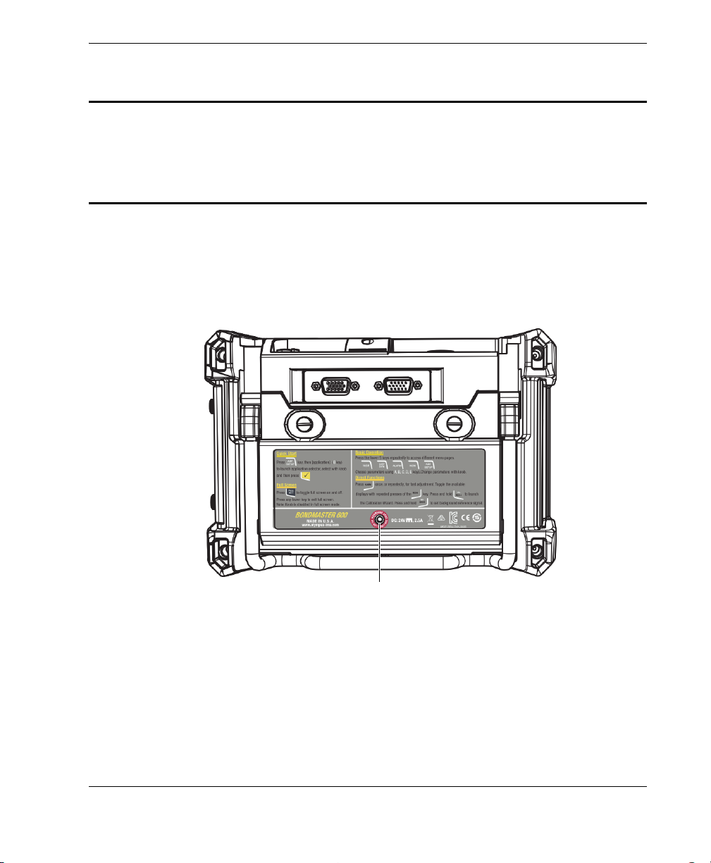
Instruction and rating label (see Table 1 on page 3)
Labels and Symbols
Safety-related labels and symbols are attached to the instrument at the locations
shown in Figure i-1 on page 1 and Figure i-2 on page 2. If any or all of the labels or
symbols are missing or illegible, please contact Olympus.
Figure i‑1 Label attached to the back of the instrument
Labels and Symbols
1
DMTA-10045-01EN, Rev. E, August 2016
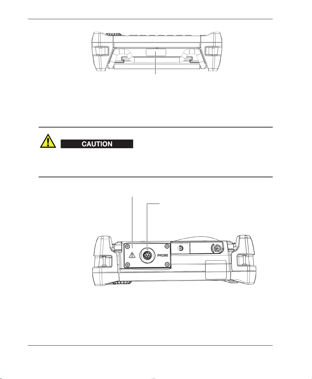
Serial number location (see Table 2 on page 4)
CAUTION
11-pin Fischer connector
Warning symbol
Figure i‑2 Location of the serial number
To avoid the risk of electric shock, do not touch the inner conductors of the 11-pin
Fischer connector. Up to 80 V can be present on the inner conductors. The warning
symbol shown in the figure below warns of this electric shock risk.
Labels and Symbols
2
Figure i‑3 The warning symbol
DMTA-10045-01EN, Rev. E, August 2016
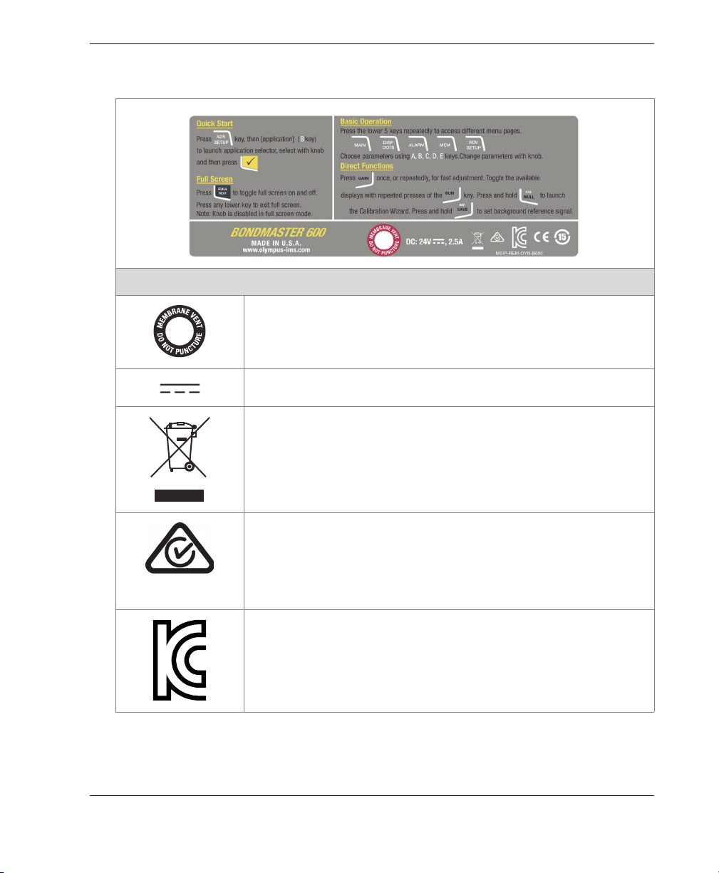
Table 1 Content of the rating label
Content
This symbol indicates the location of the membrane vent.
The direct current symbol.
The WEEE symbol indicates that the product must not be
disposed of as unsorted municipal waste, but should be
collected separately.
The regulatory compliance mark (RCM) label indicates that
the product complies with all applicable standards, and has
been registered with the Australian Communications and
Media Authority (ACMA) for placement on the Australian
market.
Seller and user shall be noticed that this equipment is suitable
for electromagnetic equipment for office work (class A) and it
can be used outside home. The MSIP code for the
BondMaster 600 is the following: MSIP-REM-OYN-B600.
Labels and Symbols
3
DMTA-10045-01EN, Rev. E, August 2016
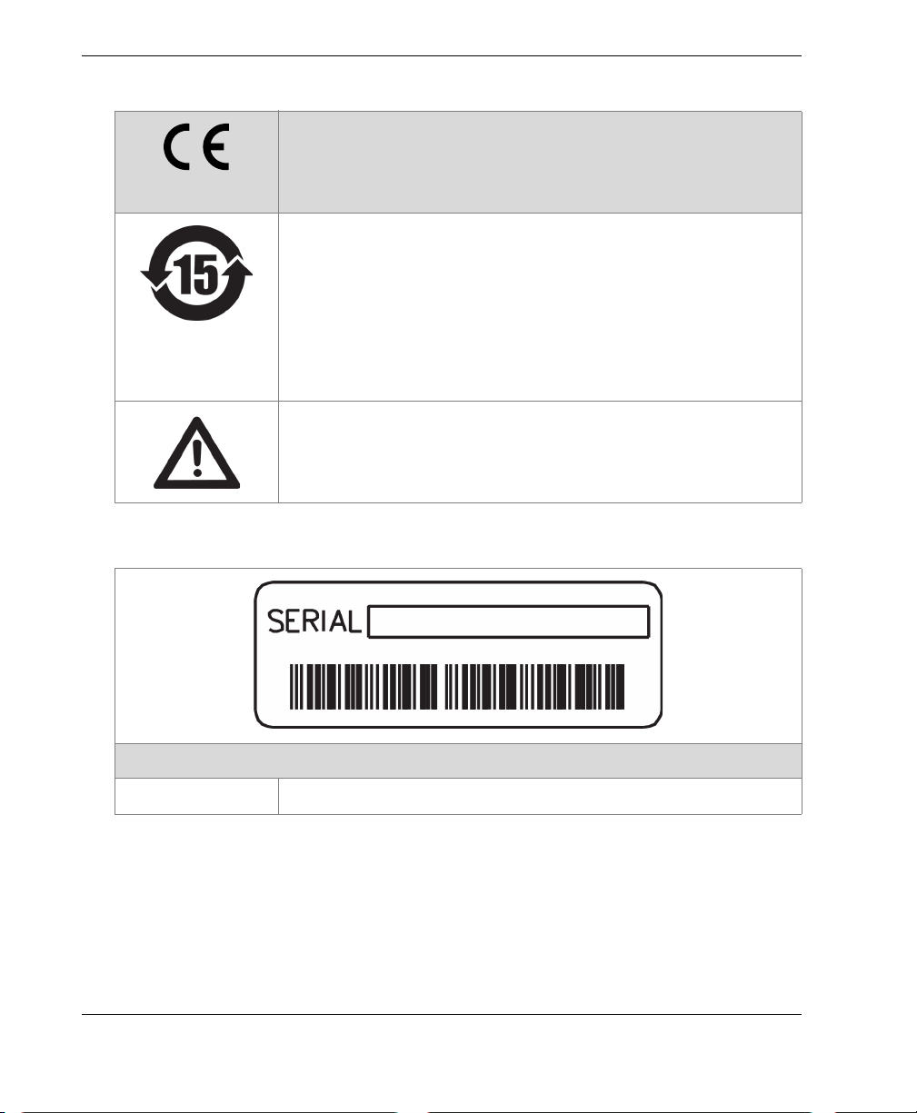
Table 1 Content of the rating label (continued)
The CE marking is a declaration that this product conforms to
all the applicable directives of the European Community. See
the Declaration of Conformity for details. Contact your Olympus
representative for more information.
The China RoHS mark indicates the product’s EnvironmentFriendly Use Period (EFUP). The EFUP is defined as the
number of years for which listed controlled substances will not
leak or chemically deteriorate while in the product. The EFUP
for the BondMaster 600 has been determined to be 15 years.
Note: The Environment-Friendly Use Period (EFUP) is not
meant to be interpreted as the period assuring functionality
and product performance.
The warning symbol indicates that the user must read the
user’s manual in order to find out the nature of the potential
hazards and any actions to avoid them.
Table 2 Content of the serial number label
SERIAL The serial number.
Labels and Symbols
4
Content

DMTA-10045-01EN, Rev. E, August 2016
WARNING
Important Information — Please Read Before Use
Intended Use
The BondMaster 600 composite bond tester is designed to perform nondestructive
inspections on industrial and commercial materials.
Do not use the BondMaster 600 for any purpose other than its intended use. It must
never be used to inspect or examine human or animal body parts.
Instruction Manual
This instruction manual contains essential information on how to use this Olympus
product safely and effectively. Before using this product, thoroughly review this
instruction manual. Use the product as instructed.
Keep this instruction manual in a safe, accessible location.
Important Information — Please Read Before Use
5
DMTA-10045-01EN, Rev. E, August 2016
IMPORTANT
CAUTION
Some of the details of components and/or software images in this manual may differ
from your instrument’s components or software display. However, the principles
remain the same.
Instrument Compatibility
Only use the BondMaster 600 instrument with the following ancillary equipment:
• Rechargeable lithium-ion (Li-ion) battery pack (Olympus P/N: 600-BAT-L-2
[U8760058])
• Optional stand-alone external battery charger (Olympus P/N: EPXT-EC-X), where
“X” denotes the power cord type (see Table 18 on page 222).
• Charger/adaptor (Olympus P/N: EP-MCA-X), where “X” denotes the power cord
type (see Table 18 on page 222).
Always use equipment and accessories that meet Olympus specifications. Using
incompatible equipment could cause equipment malfunction and/or damage, or
human injury.
Repair and Modification
The BondMaster 600 does not contain any user-serviceable parts. Opening the
instrument might void the warranty.
Important Information — Please Read Before Use
6
DMTA-10045-01EN, Rev. E, August 2016
CAUTION
DANGER
In order to prevent human injury and/or equipment damage, do not disassemble,
modify, or attempt to repair the instrument.
Safety Symbols
The following safety symbols might appear on the instrument and in the instruction
manual:
General warning symbol
This symbol is used to alert the user to potential hazards. All safety messages that
follow this symbol shall be obeyed to avoid possible harm or material damage.
Shock hazard caution symbol
This symbol is used to alert the user to potential electric shock hazards. All safety
messages that follow this symbol shall be obeyed to avoid possible harm.
Safety Signal Words
The following safety symbols might appear in the documentation of the instrument:
The DANGER signal word indicates an imminently hazardous situation. It calls
attention to a procedure, practice, or the like, which, if not correctly performed or
adhered to, will result in death or serious personal injury. Do not proceed beyond a
DANGER signal word until the indicated conditions are fully understood and met.
Important Information — Please Read Before Use
7
DMTA-10045-01EN, Rev. E, August 2016
WARNING
CAUTION
IMPORTANT
NOTE
TIP
The WARNING signal word indicates a potentially hazardous situation. It calls
attention to a procedure, practice, or the like, which, if not correctly performed or
adhered to, could result in death or serious personal injury. Do not proceed beyond a
WARNING signal word until the indicated conditions are fully understood and met.
The CAUTION signal word indicates a potentially hazardous situation. It calls
attention to an operating procedure, practice, or the like, which, if not correctly
performed or adhered to, may result in minor or moderate personal injury, material
damage, particularly to the product, destruction of part or all of the product, or loss of
data. Do not proceed beyond a CAUTION signal word until the indicated conditions
are fully understood and met.
Note Signal Words
The following safety symbols could appear in the documentation of the instrument:
The IMPORTANT signal word calls attention to a note that provides important
information, or information essential to the completion of a task.
The NOTE signal word calls attention to an operating procedure, practice, or the like,
which requires special attention. A note also denotes related parenthetical
information that is useful, but not imperative.
The TIP signal word calls attention to a type of note that helps you apply the
techniques and procedures described in the manual to your specific needs, or
provides hints on how to effectively use the capabilities of the product.
Important Information — Please Read Before Use
8
DMTA-10045-01EN, Rev. E, August 2016
WARNING
Safety
Before turning on the instrument, verify that the correct safety precautions have been
taken (see the following warnings). In addition, note the external markings on the
instrument, which are described under “Safety Symbols.”
Warnings
General Warnings
• Carefully read the instructions contained in this instruction manual prior to
turning on the instrument.
• Keep this instruction manual in a safe place for further reference.
• Follow the installation and operation procedures.
• It is imperative to respect the safety warnings on the instrument and in this
instruction manual.
• If the equipment is used in a manner not specified by the manufacturer, the
protection provided by the equipment could be impaired.
• Do not install substitute parts or perform any unauthorized modification to the
instrument.
• Service instructions, when applicable, are for trained service personnel. To avoid
the risk of electric shock, do not perform any work on the instrument unless
qualified to do so. For any problem or question regarding this instrument, contact
Olympus or an authorized Olympus representative.
• Do not touch the connectors directly by hand. Otherwise, a malfunction or electric
shock may result.
• Do not allow metallic or foreign objects to enter the device through connectors or
any other openings. Otherwise, a malfunction or electric shock may result.
Important Information — Please Read Before Use
9
DMTA-10045-01EN, Rev. E, August 2016
WARNING
CAUTION
CAUTION
Electrical Warning
The instrument must only be connected to a power source corresponding to the type
indicated on the rating label.
If an unauthorized power supply cord is used to power the instrument or charge the
batteries, Olympus cannot guarantee the electrical safety of the equipment.
Battery Precautions
• Before disposing of a battery, check your local laws, rules, and regulations, and
follow them accordingly.
• Transportation of lithium-ion batteries is regulated by the United Nations under
the United Nations Recommendations on the Transport of Dangerous Goods. It is
expected that governments, intergovernmental organizations, and other
international organizations shall conform to the principles laid down in these
regulations, thus contributing to worldwide harmonization in this field. These
international organizations include the International Civil Aviation organization
(ICAO), the International Air Transport Association (IATA), the International
Maritime Organization (IMO), the US Department of Transportation (USDOT),
Transport Canada (TC), and others. Please contact the transporter and confirm
current regulations before transportation of lithium-ion batteries.
• Do not open, crush, or perforate batteries; doing so could cause injury.
• Do not incinerate batteries. Keep batteries away from fire and other sources of
extreme heat. Exposing batteries to extreme heat (over 80 °C) could result in an
explosion or personal injury.
• Do not drop, hit, or otherwise abuse a battery, as doing so could expose the cell
contents, which are corrosive and explosive.
• Do not short-circuit the battery terminals. A short circuit could cause injury and
severe damage to a battery making it unusable.
Important Information — Please Read Before Use
10
DMTA-10045-01EN, Rev. E, August 2016
CAUTION
• Do not expose a battery to moisture or rain; doing so could cause an electric
shock.
• Only use the BondMaster 600 instrument or an external charger approved by
Olympus to charge the batteries.
• Only use batteries supplied by Olympus.
• Do not store batteries that have less than 40 % remaining charge. Recharge
batteries to between 40 % and 80 % capacity before storing them.
• During storage, keep the battery charge between 40 % and 80 %.
• Do not leave batteries in the BondMaster 600 during instrument storage.
Hearing Protection
The BondMaster 600 probes emit audible sounds that easily propagate and that are
amplified by the part being tested. The sound level is dependent on numerous factors,
including (but not limited to) part composition, frequency, extent of defect(s), and
proximity to the part being tested. Under specific test conditions, sound levels in
excess of 85 dB have been measured near the probe. Sounds of this intensity can result
in hearing fatigue and possible hearing damage after long-term exposure, and
therefore a hearing-protection program may be necessary. In particular, the
mechanical impedance analysis (MIA) and pitch-catch swept modes are capable of
generating high-pitched sounds that can cause earlier onset of hearing fatigue.
Because of the variations in part composition, test conditions, and part proximity,
OSSA (Olympus Scientific Solutions Americas) recommends that you evaluate your
particular test applications to determine if hearing protection is required.
Equipment Disposal
Before disposing of the BondMaster 600, check your local laws, rules, and regulations,
and follow them accordingly.
Important Information — Please Read Before Use 11
DMTA-10045-01EN, Rev. E, August 2016
CE (European Community)
This device complies with the requirements of both directive
2014/30/EU concerning electromagnetic compatibility and directive
2014/35/EC concerning low voltage. The CE marking indicates
compliance with the above directives.
WEEE Directive
In accordance with European Directive 2012/19/EU on Waste Electrical
and Electronic Equipment (WEEE), this symbol indicates that the
product must not be disposed of as unsorted municipal waste, but
should be collected separately. Refer to your local Olympus distributor
for return and/or collection systems available in your country.
China RoHS
China RoHS is the term used by industry generally to describe legislation
implemented by the Ministry of Information Industry (MII) in the People’s Republic
of China for the control of pollution by electronic information products (EIP).
The China RoHS mark indicates the product’s EnvironmentFriendly Use Period (EFUP). The EFUP is defined as the number of
years for which listed controlled substances will not leak or
chemically deteriorate while in the product. The EFUP for the
BondMaster 600 has been determined to be 15 years.
Note: The Environment-Friendly Use Period (EFUP) is not meant
to be interpreted as the period assuring functionality and product
performance.
“ 中国 RoHS” 是一个工业术语,一般用于描述中华人民共和国信息工业部 (MII)针
对控制电子信息产品 (EIP)的污染所实行的法令。
Important Information — Please Read Before Use
12

DMTA-10045-01EN, Rev. E, August 2016
中国 RoHS 标识是根据 “ 电器电子产品有害物质限制使用管理办
法 ” 以及 “ 电子电气产品有害物质限制使用标识要求 ” 的规定,适
用于在中国销售的电气电子产品上的电气电子产品有害物质限制使
用标识。
电气电子产品
有害物质
限制使用标识
部件名称 铅及其
机构部件
主体 光学部件
电气部件
附件
本表格依据 SJ/T 11364 的规定编制。
○:表示该有害物质在该部件所有均质材料中的含量均在 GB/T26572 规定的限量要求以下。
×:表示该有害物质至少在该部件的某一均质材料中的含量超出 GB/T26572 规定的限量要求。
注意:电气电子产品有害物质限制使用标识内的数字为在正常的使
用条件下有害物质不会泄漏的年限,不是保证产品功能性的年限。
产品中有害物质的名称及含量
有害物质
汞及其
化合物
(Pb) (Hg) (Cd)
× ○○○○○
× ○○○○○
× ○○○○○
× ○○○○○
化合物
镉及其
化合物
六价铬及
其化合物
(Cr( Ⅵ ))
多溴联苯 多溴
二苯醚
(PBB) (PBDE)
Korea Communications Commission (KCC)
A 급 기기 ( 업무용 방송통신기자재 )
이 기기는 업무용 (A 급 ) 전자파적합기기로서 판 매자 또는 사용자는 이 점을주의하시
기 바라 며 , 가정외의 지역에서 사용하는 것을 목적으로 합니다 .
Important Information — Please Read Before Use 13

DMTA-10045-01EN, Rev. E, August 2016
EMC Directive Compliance
This equipment generates and uses radio-frequency energy and, if not installed and
used properly (that is, in strict accordance with the manufacturer’s instructions), may
cause interference. The BondMaster 600 has been tested and found to comply with the
limits for an industrial device in accordance with the specifications of the EMC
directive.
FCC (USA) Compliance
This device complies with Part 15 of the FCC Rules. Operation is subject to the
following two conditions:
1. This device may not cause harmful interference.
2. This device must accept any interference received, including interference that
may cause undesired operation.
Changes or modifications not expressly approved by the party responsible for
compliance could void the user’s authority to operate the equipment.
This equipment has been tested and found to comply with the limits for a Class A
digital device, pursuant to Part 15 of the FCC Rules. These limits are designed to
provide reasonable protection against harmful interference when the equipment is
operated in a commercial environment. This equipment generates, uses, and can
radiate radio frequency energy, and if not installed and used in accordance with the
instruction manual, might cause harmful interference to radio communications.
Operation of this equipment in a residential area is likely to cause harmful
interference, in which case you will be required to correct the interference at your own
expense.
ICES-001 (Canada) Compliance
This Class A digital apparatus complies with Canadian ICES-001.
Cet appareil numérique de la classe A est conforme à la norme NMB-001 du Canada.
Important Information — Please Read Before Use
14

DMTA-10045-01EN, Rev. E, August 2016
Warranty Information
Olympus guarantees your Olympus product to be free from defects in materials and
workmanship for a specific period, and in accordance with conditions specified in the
Olympus Scientific Solutions Americas Inc. Terms and Conditions available at
http://www.olympus-ims.com/en/terms/.
The Olympus warranty only covers equipment that has been used in a proper
manner, as described in this instruction manual, and that has not been subjected to
excessive abuse, attempted unauthorized repair, or modification.
Inspect materials thoroughly on receipt for evidence of external or internal damage
that might have occurred during shipment. Immediately notify the carrier making the
delivery of any damage, because the carrier is normally liable for damage during
shipment. Retain packing materials, waybills, and other shipping documentation
needed in order to file a damage claim. After notifying the carrier, contact Olympus
for assistance with the damage claim and equipment replacement, if necessary.
This instruction manual explains the proper operation of your Olympus product. The
information contained herein is intended solely as a teaching aid, and shall not be
used in any particular application without independent testing and/or verification by
the operator or the supervisor. Such independent verification of procedures becomes
increasingly important as the criticality of the application increases. For this reason,
Olympus makes no warranty, expressed or implied, that the techniques, examples, or
procedures described herein are consistent with industry standards, nor that they
meet the requirements of any particular application.
Olympus reserves the right to modify any product without incurring the
responsibility for modifying previously manufactured products.
Technical Support
Olympus is firmly committed to providing the highest level of customer service and
product support. If you experience any difficulties when using our product, or if it
fails to operate as described in the documentation, first consult the user’s manual, and
then, if you are still in need of assistance, contact our After-Sales Service. To locate the
nearest service center, visit the Service Centers page at: http://www.olympusims.com.
Important Information — Please Read Before Use 15

DMTA-10045-01EN, Rev. E, August 2016
Important Information — Please Read Before Use
16
DMTA-10045-01EN, Rev. E, August 2016
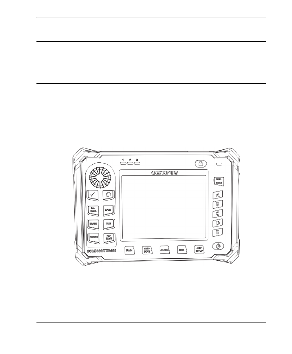
Introduction
This user’s manual provides operating instructions for the Olympus BondMaster 600
composite bond tester, which uses acoustic and ultrasonic waves to detect surface
flaws in various types of composite materials (see Figure i-4 on page 17). The
manual’s information is organized to explain the BondMaster 600 technology, safety
details, hardware, and software.
Figure i‑4 BondMaster 600
Introduction 17

DMTA-10045-01EN, Rev. E, August 2016
18
Introduction

DMTA-10045-01EN, Rev. E, August 2016
1. Package Contents
The BondMaster 600 is available in two different models:
• B600: Basic instrument featuring all pitch-catch modes
• B600M: Multi-mode instrument including pitch-catch, mechanical impedance
analysis (MIA), and resonance modes
Before using the BondMaster 600 for the first time, you must inspect the package
contents to make sure there are no missing or defective items.
1.1 Unpacking
All cartons should be opened and inspected upon receipt. The cartons and contents
should be inspected for any signs of damage that may have occurred during
shipment. If damage is noted, contact the carrier and retain the damaged shipping
materials until an inspection can be performed by a representative of the carrier. With
the exception of the universal battery charger/adaptor and external accessories, all
BondMaster 600 options are installed before the instrument is shipped. Check the
contents of the carton or cartons against the packing list to ensure that all ordered
accessories have been received.
1.2 Initial Inspection
After the BondMaster 600 has been unpacked and the contents of the carton have been
checked against the packing list, a visual inspection and a basic operation test should
be performed as follows:
Package Contents 19

DMTA-10045-01EN, Rev. E, August 2016
To perform the initial inspection
1. Check if there is cosmetic or structural damage to the packaging and the
BondMaster 600.
2. Turn on the BondMaster 600 power.
3. Let the BondMaster 600 perform the “Power-On Self Test.”
4. Confirm that the “Sign-On” message is displayed.
1.3 Contents of the Case
The BondMaster 600 comes with several key accessories (see Figure 1-1 on page 21):
• Calibration certificate (Olympus P/N: B600-CERT [U8010093]).
• Charger/adaptor (Olympus P/N: EP-MCA-X), where “X” denotes the AC power
cord type (see Table 18 on page 222).
• AC power cord
• Transport case (Olympus P/N: 600-TC [U8780294])
• Getting Started Guide (Olympus P/N: DMTA-10044-01XX, where “XX” denotes the
language (see Table 20 on page 222 for order numbers)
• BondMaster 600 User’s Manual and PC interface program on CD-ROM (Olympus
P/N: B600-CD [U8141002])
• MicroSD Memory Card, 2 GB (Olympus P/N: MICROSD-ADP-2GB [U8779307])
• USB communication cable (Olympus P/N: EPLTC-C-USB-A-6 [U8840031])
• 600 Series rechargeable Li-ion battery; 10.8 V, 6.8 Ah, 73 Wh
(Olympus P/N: 600-BAT-L-2 [U8760058])
• 8-cell battery holder with connector plug (Olympus P/N: 600-BAT-AA
[U8780295])
• Pitch-catch and MIA mode cable for BondMaster 600; 3.3 m (11 ft) length, 11-pin
to 11-pin connectors (Olympus P/N: SBM-CPM-P11 [U8800058])
• Resonance mode cable for BondMaster 600; 1.8 m (6 ft) length, 11-pin to 6-pin
connectors (Olympus P/N: SBM-CR-P6 [U8800059])
• Factory-installed wrist strap on left side of BondMaster 600 (Olympus P/N:
38DLP-HS [U8779371])
20
Chapter 1
 Loading...