

Page 1
Page 2

Every effort has been made to ensure that the information in this document is complete,
accurate, and up-to-date. Okidata assumes no responsibility for the results of errors
beyond its control. Okidata also cannot guarantee that changes in software and equipment
made by other manufacturers and referred to in this guide will not affect the applicability
of the information in it. Mention of software products manufactured by other companies
does not necessarily constitute endorsement by Okidata.
© 2007 by Oki Data, Americas. All rights reserved.
Rev 1.1 February, 2007.
Written and produced by the Okidata Training & Publications Department. Please address
any comments by mail to:
Training & Publications Department
Okidata, Division of Oki America, Inc.
2000 Bishops Gate Blvd.
Mount Laurel, NJ 08054-4620
or by email to
pubs@okidata.com
For the latest product information and manuals, we welcome you to visit our web site:
http://www.okidata.com
Year 2000 Compliance
All products currently sold by Okidata are Year 2000 Compliant. Each product contains
information technology that accurately processes date and time data between the years
1999 and 2000. These products, when used in combination with products purchased from
other manufacturers, whose products properly exchange date and time information, will
accurately process the date and time. All future products are committed to meeting the
same Year 2000 compliance.
ENERGY STA R
OKI and OKIDATA are registered trademarks/marques déposées/marcas registradas Oki Electric Industry
Company , Ltd.
Epson is a registered trademark of Epson America, Inc. Ethernet is a trademark of Digital Equipment Corporation.
IBM is a registered trademark of International Business Machines Corp. Microsoft and Windows are
registered trademarks or trademarks of Microsoft Corporation in the U.S. and/or other countries.
®
2
Page 3

Conventions Used in this Users Guide
Notes
Note: Notes are set in regular type and contain general information.
Cautions
Caution! Cautions are set in bold italics and contain information regarding actions
which could potentially cause personal injury or damage to the printer.
Important Information
Important! Important information is set in italics.
3
Page 4

Contents
1: Front Panel.................................................................................................................... 8
Print Mode: Indicator Lights.......................................................................................... 8
Print Mode: Control Panel Buttons ................................................................................ 9
Menu Mode: Control Panel Buttons ............................................................................ 10
Menu Mode: Configuring Your Printer........................................................................ 11
Entering/Exiting the Menu Mode.............................................................................. 11
Changing the Menu Settings ..................................................................................... 11
Saving Configurations............................................................................................... 11
Switching Back and Forth between Configurations.................................................. 12
Resetting the Menu.................................................................................................... 12
Printing a List of Menu Items ................................................................................... 12
Summary of Menu Settings....................................................................................... 13
Explanation of Menu Settings...................................................................................... 17
2: Maintenance................................................................................................................ 22
Replacing the Ribbon................................................................................................... 22
Clearing Paper Jams..................................................................................................... 25
Front Feed Jams ........................................................................................................ 25
Rear Feed Jams.......................................................................................................... 27
Replacing the Power Fuse............................................................................................ 28
Cleaning the Housing................................................................................................... 29
Cleaning the Interior.................................................................................................. 29
Cleaning the Exterior ................................................................................................ 30
3: Troubleshooting .......................................................................................................... 31
General Troubleshooting.............................................................................................. 31
Error Messages............................................................................................................. 34
4
Page 5

4: Service Information.................................................................................................... 38
Getting Service & Support........................................................................................... 38
Your Dealer ............................................................................................................... 38
Okidata Information System Automated Attendant .................................................. 38
Okidata Customer Support Professionals) ................................................................ 39
Okidata Service Locations ........................................................................................ 40
Purchasing Replacement Parts & Accessories .......................................................... 41
Accessories................................................................................................................ 42
OkiLAN Model 6100e Ethernet Network Interface Card ..................................... 42
OKI Adapter Card.................................................................................................. 42
Replacement Parts ..................................................................................................... 42
A: Specifications.............................................................................................................. 44
General Specifications ................................................................................................. 44
Font Specifications....................................................................................................... 45
Reliability.....................................................................................................................46
Paper Specifications..................................................................................................... 46
Front Feed ................................................................................................................. 46
Rear Feed................................................................................................................... 47
Physical Specifications ................................................................................................ 47
Environmental Specifications ...................................................................................... 47
Electrical Specifications............................................................................................... 48
Memory........................................................................................................................ 48
B: Interfacing ..................................................................................................................49
Parallel Interface .......................................................................................................... 49
Parallel Interface Pin Assignments............................................................................ 49
Serial Interface ............................................................................................................. 51
Serial Interface Pin Assignments............................................................................... 51
Commonly Used Serial Cable Configurations .......................................................... 52
Serial Interface Test ................................................................................................... 53
Ethernet 10/100 BaseT Interface.................................................................................. 54
Pin Assignments ........................................................................................................ 54
Print Server Parallel Output Pin Assignments........................................................... 55
5
Page 6

C: Command Summary ................................................................................................. 56
Epson FX Command Summary ................................................................................... 56
IBM Proprinter III Command Summary...................................................................... 69
Okidata Microline Standard Command Summary....................................................... 79
Bar Code Commands ................................................................................................... 91
Select Bar Code Type and Size Command ................................................................ 91
Print Bar Code Data Command................................................................................. 93
Postnet Bar Code Command ..................................................................................... 93
Custom Font Commands: Epson & IBM..................................................................... 94
Epson FX Custom Font Command ........................................................................... 94
IBM Proprinter III Custom Fonts Command ............................................................ 96
Select Menu Item 1 Command..................................................................................... 98
Select Menu Item 2 Command................................................................................... 105
D: Hex Dump Mode.......................................................................................................111
Running a Hexadecimal Dump ...................................................................................111
E: Character Sets.......................................................................................................... 112
Lower ASCII Character Sets...................................................................................... 112
Upper ASCII Character Sets ...................................................................................... 116
Epson International Character Substitutions.............................................................. 120
IBM International Character Substitutions ................................................................ 120
Microline Standard International Character Substitutions ......................................... 121
Code Page Character Sets .......................................................................................... 122
IBM Multilingual Code Page Sets ............................................................................. 126
Multilingual 858 Code Page Character Set................................................................ 128
ISO 8859-15 Code Page Character Set ...................................................................... 128
Epson BRASCII Character Set .................................................................................. 128
Epson Abicomp Character Set ................................................................................... 128
OKI Block Graphics Character Set ............................................................................ 129
Bar Codes................................................................................................................... 130
UPC A ..................................................................................................................... 130
UPC E...................................................................................................................... 130
EAN 8...................................................................................................................... 130
EAN 13.................................................................................................................... 130
Code 39 ................................................................................................................... 130
Code 128 ................................................................................................................. 130
Interleaved 2 of 5..................................................................................................... 130
Postnet ..................................................................................................................... 130
6
Page 7

FCC / IC / CE................................................................................................................ 131
FCC Declaration of Conformity ................................................................................ 131
Federal Communications Commission Radio Frequency Interference Statement..... 132
Industry Canada Radio Interference Statement.......................................................... 132
European Union Council of the European Communities Statement
of Electromagnetic Conformance............................................................................. 132
Warranty ....................................................................................................................... 133
Limited Warranty ....................................................................................................... 133
On-Site Repair......................................................................................................... 133
Index .............................................................................................................................. 135
7
Page 8
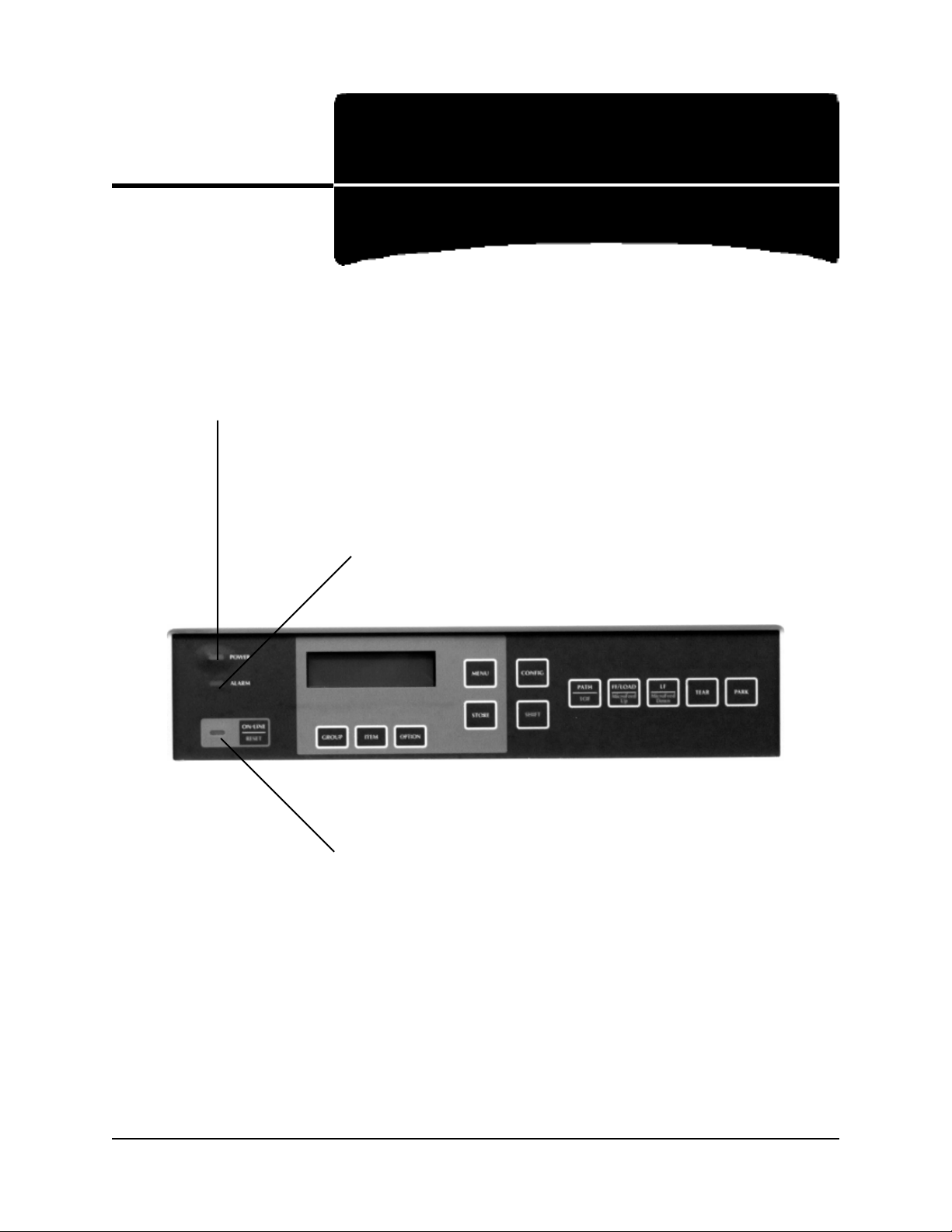
Print Mode: Indicator Lights
Power Light:
On/off: printer on/off.
Alarm Light:
On: printer error such as paper out, paper jam, etc.
Blinking: printer error such as ROM/RAM error, spacing error, etc.
1: Front Panel
Status Light:
On: printer is ready to receive data
Blinking: printer in Print Suppress mode
8
Page 9
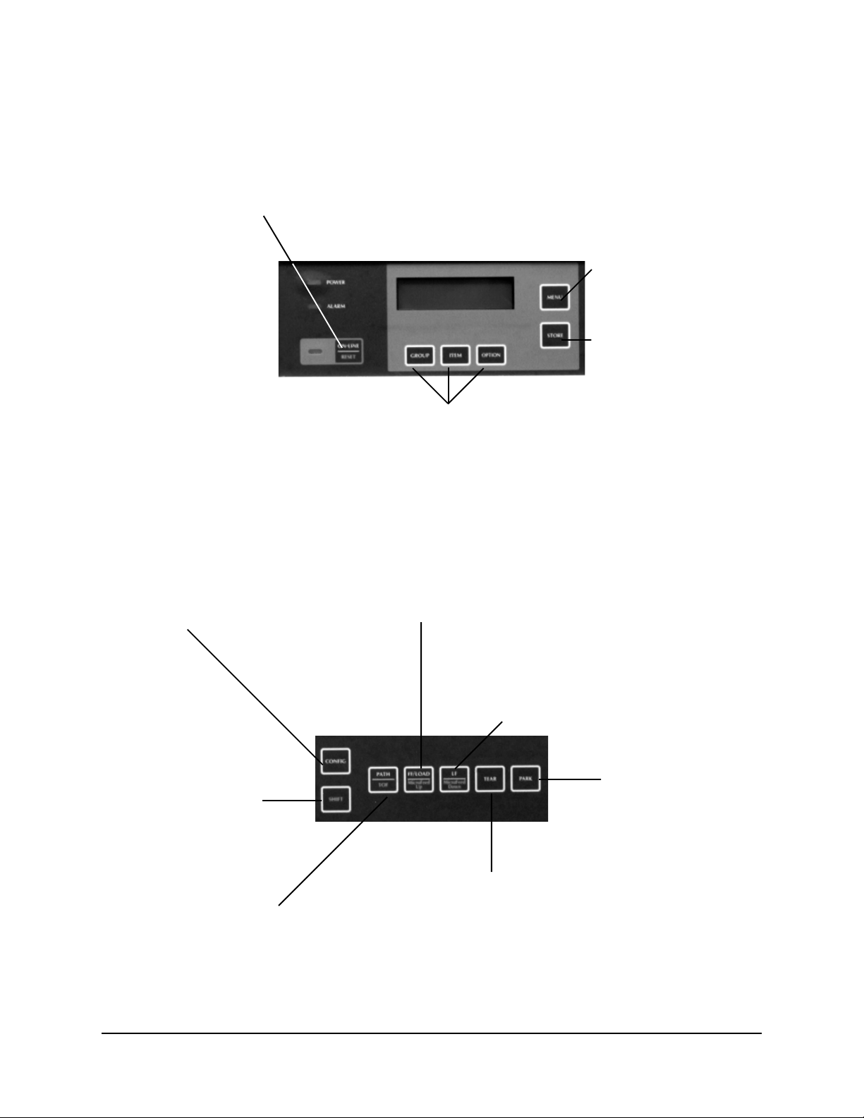
Print Mode: Control Panel Buttons
ON-LINE/RESET Button:
Press: switches printer on/off line.
With SHIFT, hold to reset printer.
With SHIFT and printer off-line, press to initialize printer.
GROUP / ITEM / OPTION Buttons:
For use in Menu Mode.
MENU Button:
Press to enter Menu mode.
STORE Button:
No function during printing
CONFIG Button:
With printer off-line and no data
being sent: press to switch between
menu configurations CFG1 and CFG2.
See Section 1 for information on how
to set CFG1 and CFG2.
SHIFT Button:
Press and hold to engage
alternate (lower) button
functions.
PATH/TOF Button:
With printer off-line:
Press to switch paper paths.
Hold to set current paper position as Top of Form.
FF/LOAD/Micro Feed Up Button:
Press to move paper to next Top of Form.
If paper is parked, press to feed paper into print position.
With SHIFT, press for fine line feeds (1/144-inch increments).
LF/Micro Feed Down Button:
Press to execute line feed.
With SHIFT, press for reverse fine line feeds
(1/144-inch increment).
PARK Button:
Press to park continuous
form currently in paper
path.
TEAR Button:
Press to move form up to tear position
9
Page 10
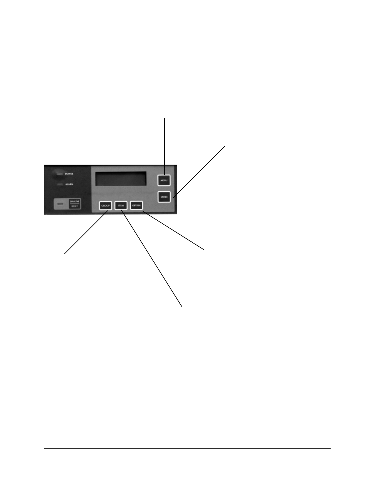
Menu Mode: Control Panel Buttons
MENU Button:
Press to exit Menu mode.
With SHIFT, press to print out a listing of current Menu settings.
STORE Button:
Press to save the new
setting.
GROUP Button:
Press to page through available
groups in the menu.
With SHIFT, press to page
backwards through available
groups.
OPTION Button:
Press to pages through available setting values
for the selected item.
With SHIFT, press to page backwards through
available setting values.
ITEM Button:
Press to page through available items for the selected
group.
With SHIFT, press to page backwards through available
items.
10
Page 11

Menu Mode: Configuring Your Printer
Entering/Exiting the Menu Mode
To enter or exit the menu mode, press MENU.
Changing the Menu Settings
To change menu settings:
1.Press
2.Press
MENU to place the printer in the menu mode.
GROUP until the group in which you wish to make a change appears on the
second line of the display.
3.Press
4.Press
ITEM until the item which you wish to change appears on the display.
OPTION until the value you wish to set for that item appears on the second line
of the display.
5.Press
STORE to save the setting.
An asterisk (*) will appear next to the value on the display.
6.Repeat steps 2 through 5 for each item you wish to change in the menu.
7.Press
MENU to exit the menu mode.
For example, to change to 12 cpi pitch:
1.Press
2.Press
3.Press
MENU.
GROUP until Font appears on the display.
ITEM until Pitch appears on the display.
4.Press
5.Press
OPTION until 12 CPI appears on the display.
STORE.
An asterisk (*) appears next to 12 CPI.
6.Press
MENU.
Saving Configurations
You can establish two user-defined groups of menu settings—CFG1 and CFG2—then
switch back and forth between them.
When you first start up your printer, both CFG1 and CFG2 are set to the same settings as
the factory settings. You will see CFG1 (Configuration 1) at the end of the second line of
the printer display.
If you enter the menu and change settings, the new settings will automatically be stored
under the configuration—CFG1 or CFG2—which appears on the second line of the
display when you make the changes.
11
Page 12
You can change either CFG1 or CFG2 back to the factory settings at any time: see
“Resetting the Menu” below.
Note: The following menu items cannot be set separately for CFG1 and CFG2:
Registration 1 through Registration 7 in the Set-Up group.
Switching Back and Forth between Configurations
To switch from CFG 1 to CFG 2, or vice versa:
1.Press
2.Press
ON-LINE/RESET to place the printer off-line.
CONFIG.
The CFG designation on the second line of the display changes.
3.Press
ON-LINE/RESET to place the printer back on-line.
The new CFG designation appears on the second line of the display.
Resetting the Menu
You can reset the menu to the original factory settings, or engage one of the user-set
values—CFG1 or CFG2—as the default.
To switch to a particular set of values, turn the printer off then:
To engage: Press and hold while turning printer on:
Factory Settings
OPTION + STORE
CFG1 Settings as default GROUP + ITEM
CFG2 Settings as default ITEM + OPTION
Printing a List of Menu Items
To print out a listing of the current menu settings:
1. Press
2. Press
3. Press
ON-LINE/RESET to place the printer off-line.
MENU to enter the menu.
SHIFT and MENU at the same time.
The menu prints.
4. Press
ON-LINE/RESET to exit the menu and place the printer back on-line.
12
Page 13
Summary of Menu Settings
Note: Factory settings are indicated by bold italics.
Group Item Settings
Printer Control Emulation Mode IBM-PPR, EPS-FX, OKI-ML
Font Print Mode Utility, NLQ Courier, NLQ Gothic, HSD
Pitch 10 CPI, 12 CPI, 15 CPI, 17.1 CPI, 20 CPI
Prop. Spacing No, Yes
Style Normal, Italics
Size Single, Double
Symbol Sets Character Set Set I (IBM/Epson), Set II (IBM/Epson),
Standard (ML), Line Graphics (ML),
Block Graphics (ML)
Language Set American, French, German, British, Danish I,
Swedish, Italian, Spanish I, Japanese, Norwegian,
Danish II, Spanish II, Latin American,
French Canadian, Dutch, Publisher
Zero Character Slashed, Unslashed
Code Page USA, Canada French, Multilingual, Portugal,
Norway, BRASCII, Abicomp, Multilingual 858,
ISO 8859/15
Rear Feed Line Spacing 6 LPI, 8 LPI
Form T ear-Off Off, 500ms, 1 sec, 2 sec
Skip Over Perf. No, Yes
Page Width 13.6", 8"
Page Length 11", 11-2/3", 12", 14", 17", 3", 3.5", 4", 5", 5.5",
6", 7", 8", 8.5"
13
Page 14
Group Item Settings
Front Feed Line Spacing 6 LPI, 8 LPI
Form Tear-Off Off, 500ms, 1 sec, 2 sec
Skip Over Perf. No, Yes
Page Width 13.6", 8"
Page Length 11", 11-2/3", 12", 14", 17", 3", 3.5", 4", 5", 5.5",
6", 7", 8", 8.5"
Set-Up Graphics Bi-directional, Uni-directional
# Graphic Bits 8, 7
[ML emulation only]
Rcv. Buffer 1 Line, 16K, 28K, 56K (No DLL)
Ppr Out Override No, Yes
Registration 1 0.25 mm Right, 0.20 mm Right, 0.15 mm Right,
0.10 mm Right, 0.05 mm Right, 0, 0.05 mm
Left, 0.10 mm Left, 0.15 mm Left, 0.20 mm
Left, 0.25 mm Left.
Registration 2 0.25 mm Right, 0.20 mm Right, 0.15 mm Right,
0.10 mm Right, 0.05 mm Right, 0, 0.05 mm
Left, 0.10 mm Left, 0.15 mm Left, 0.20 mm
Left, 0.25 mm Left.
Registration 3 0.25 mm Right, 0.20 mm Right, 0.15 mm Right,
0.10 mm Right, 0.05 mm Right, 0, 0.05 mm
Left, 0.10 mm Left, 0.15 mm Left, 0.20 mm
Left, 0.25 mm Left.
Registration 4 0.25 mm Right, 0.20 mm Right, 0.15 mm Right,
0.10 mm Right, 0.05 mm Right, 0, 0.05 mm
Left, 0.10 mm Left, 0.15 mm Left, 0.20 mm
Left, 0.25 mm Left.
Registration 5 0.25 mm Right, 0.20 mm Right, 0.15 mm Right,
0.10 mm Right, 0.05 mm Right, 0, 0.05 mm
Left, 0.10 mm Left, 0.15 mm Left, 0.20 mm
Left, 0.25 mm Left.
Registration 6 0.25 mm Right, 0.20 mm Right, 0.15 mm Right,
0.10 mm Right, 0.05 mm Right, 0, 0.05 mm
Left, 0.10 mm Left, 0.15 mm Left, 0.20 mm
Left, 0.25 mm Left.
14
Page 15
Group Item Settings
Set-Up (cont.) Registration 7 0.25 mm Right, 0.20 mm Right, 0.15 mm Right,
0.10 mm Right, 0.05 mm Right, 0, 0.05 mm
Left, 0.10 mm Left, 0.15 mm Left, 0.20 mm
Left, 0.25 mm Left.
Data W ord Size 8, 7
[ML emulation only]
Op. Panel Function Full Operation, Limit Operation
Reset Inhibit No, Yes
Print Suppress No, Yes
Auto LF No, Yes
Auto CR No, Yes
[ML emulation only]
Print DEL Code No, Yes
[ML emulation only]
SI Pitch (10) 15 CPI, 17.1 CPI
[IBM emulation only]
SI Pitch (12) 12 CPI, 20 CPI
[IBM emulation only]
Time Out Print Valid, Invalid
Auto Select No, Yes
ESC SI Pitch 17.1 CPI, 20 CPI
[IBM emulation only]
Intr Chr Sub St Combined, Code Page Only
[Epson emulation only]
Host Interface Auto Interface, Parallel, Serial,
OKI HSP (print server installed),
Opt. Card (optional card installed)
I/F Time Out 15 sec, 30 sec, 45 sec, 1 min, 2 min, 3 min, 4 min,
5 min
Default Path Current Path, Rear Path, Front Path
Auto Path Invalid, Valid
Impact Mode Normal, Quiet, Hi-Impact Copy
15
Page 16
Group Item Settings
Set-Up (cont.) LF Speed Fast, Slow
Width Control Invalid, Mode 1, Mode 2
Parallel I/F I-Prime Invalid, Buffer Print, Buffer Clear
Pin 18 +5V, Open
Auto Feed XT Valid, Invalid
[Epson emulation only]
Bi-Direction Enable, Disable
Serial I/F Parity None, Odd, Even
# Serial Bits 8 Bits, 7 Bits
Protocol Ready/Busy, X-ON/X-OFF
Diagnostic T est No, Y es
Busy Line SSD-, SSD+, DTR, RTS
Baud Rate 9600 BPS, 4800 BPS, 2400 BPS, 1200 BPS,
600 BPS, 300 BPS, 19200 BPS, 38400 BPS
DSR Signal Valid, Invalid
DTR Signal Rdy on Pwr Up, Ready on Select
Busy Time 200 ms, 1 sec
16
Page 17

Explanation of Menu Settings
The items in the table below are arranged in alphabetical order.
Item Description Emulations Group(s)
# Graphic Bits Choose the graphics your system uses: ML only Set-Up
7 or 8 dots in each column printed.
# Serial Bits Change to 7 Bits if your system uses a All Serial I/F
7-bit data format.
Auto CR If you want the printer to automatically add IBM only Set-Up
a carriage return when a Line Feed is
received at the end of a line, change the
setting to Yes.
Auto Feed XT If your system uses pin 14 of the parallel Epson only Parallel I/F
interface to control automatic line feed,
change the setting to Valid.
Auto LF If your printout is consistently double All Set-Up
spaced, select No; if it overprints, select Yes.
Auto Path Invalid = paper path controlled by software; All Set-Up
Valid = paper path controlled by printer;
paper automatically switches to the alternate
path when current paper runs out.
Auto Select If you always use the same Top of Form All Set-Up
position, change the setting to Valid.
Baud Rate Sets the data transmission speed for the All Serial I/F
serial interface.
Bi-Direction Change to disable if you wish to All Parallel I/F
disengage bi-directional communication at
the parallel interface.
Busy Line If the Ready/Busy protocol (factory setting) All Serial I/F
is selected, use this to select which line your
system monitors for a busy signal.
Busy Time Sets the length of the busy signal when the All Serial I/F
Ready/Busy protocol (factory setting) is
engaged.
Character Set Determines the character set the printer uses. All Symbol Sets
Code Page Sets the Code Page set the printer uses: All Symbol Sets
which selections appear depends on the
emulation selected.
17
Page 18
Item Description Emulations Group(s)
Data Word Size If your computer system uses seven bits ML only Set-Up
to make up each unit of data, change this
setting to 7.
Default Path Change to Rear Path or Front Path if you All Set-Up
wish the printer to use that paper path
as its default.
Diagnostic Test Change to Yes if you want to perform a All Serial I/F
diagnostic test of the serial interface
(see Appendix B: Interfacing).
DSR Signal Used with Ready/Busy protocol (factory All Serial I/F
setting) to determine the way your system
handles the DSR (Data Set Ready) signal.
DTR Signal Change to Ready on Select if the DTR All Serial I/F
(Data Terminal Ready) signal is required
when the printer is selected; leave as
Ready on Power Up if the DTR signal is
required when the printer is turned on.
Emulation Mode Sets the printer emulation. Not Printer
applicable Control
ESC SI Pitch Sets the character pitch used when the IBM only Set-Up
ESC SI command is received by the
printer .
Form Tear-Off Select 500 ms, 1 second, or 2 seconds to All Rear Feed,
turn the Form Tear-Off feature on and to Front Feed
set the time interval for the printer to wait
before advancing the paper to the tear-off
position.
Graphics Change to uni-directional printing to All Set-Up
improve alignment between print lines
when printing graphics. This will slow
down the printing. Alternately, you can
leave Bi-directional enabled and optimize
graphics printing by adjusting the print
registration setting in the Set-Up group.
18
Page 19
Item Description Emulations Group(s)
Host Interface If you wish to select a dedicated interface All Set-Up
rather than having the printer automatically
detect the interface being used, select
parallel, serial, OKI HSP (appears only if
the print server is installed), or Opt. Card
(appears only if optional card is installed).
I/F Time Out Sets the length of time the printer will All Set-Up
wait for additional data to be received
at the interface.
Impact Mode Change to Quiet for minimum sound; All Set-Up
change to Hi-Impact Copy for forms
thicker than 7-part carbonless.
Intr Chr Sub St International Character Sub Set: change Epson only Set-Up
to Code page Only if you wish the
printer to ignore the Language Set.
I-Prime Determines what the printer will do All Parallel I/F
when it receives the I-Prime signal from
the software: Buffer Print prints out the
buffer contents before resetting; Buffer
Clear dumps the buffer contents
immediately . Invalid causes the printer
to ignore the I-Prime command.
Language Set Replaces certain standard symbols with All Symbol Sets
special characters used in foreign
languages.
LF Speed Change to Slow if you wish to reduce the All Set-Up
speed with which the printer executes the
line feed command when using thicker
forms.
Line Spacing Change to 8 lines per inch to get more All Rear Feed,
lines per page. Front Feed
Op. Panel Operator Panel Function: Change to All Set-Up
Function Limited Operation to deactivate the
MENU, GROUP, ITEM, OPTION,
STORE and CONFIG buttons. This
prevents these from being changed from
the control panel when several people
are using the printer.
Page Length Sets the length of the continuous forms All Rear Feed,
you are using. Front Feed
19
Page 20
Item Description Emulations Group(s)
Page Width Change to 8" if you are using 9-inch All Rear Feed,
continuous forms. For continuous forms Front Feed
less than 9 inches wide, the page width
must be set using software.
Caution! If the page width is set
narrower than the continuous forms
being used, the printhead will print
directly on the platen: this can
damage the printhead.
Parity Sets the type of parity your system uses. All Serial I/F
Pin 18 Sets the signal on pin 18 of the parallel All Parallel I/F
interface to +5 volts or to open.
Pitch Sets the character width in characters All Font
per inch.
Ppr Out Override Paper Out Override: Senses when less All Set-Up
than 1" (25 mm) of paper remains and
stops printing. Change to Yes to override
the sensor. Caution!! This can cause loss
of data and damage the printhead!
Print DEL Code Change to Yes if you wish to print the DEL ML only Set-Up
code (decimal 27) as a solid box.
Print Mode Sets the typeface used: Utility, NLQ All Font
(Near letter Quality) Courier, NLQ
(Near Letter Quality) Gothic, or
HSD (High Speed Draft).
Print Suppress If you wish to enable the print suppress All Set-Up
command, change the setting to Yes. If
you select Yes, the printer will ignore all
data after it receives the print suppress
command.
Prop. Spacing Change to yes if you wish to engage All Font
proportionally spaced printing.
Protocol Switch to X-ON/X-OFF if that is the All Serial I/F
serial interface protocol you are using.
Rcv . Buffer Sets the size of the receive buffer. All Set-Up
20
Page 21
Item Description Emulations Group(s)
Registration 1 Change the setting as required to obtain the All Set-Up
through best registration for bi-directional printing.
Registration 7 Each time you press OPTION, the next
setting appears on the display and the
printer prints a sample showing the
alignment for that setting. Press STORE to
select the setting with the best alignment
(asterisk appears next to the setting)
before exiting the menu.
Reset Inhibit Change to Yes to prevent your software All Set-Up
from resetting your printer’s settings.
SI Pitch (10) Sets the pitch to be engaged when the IBM only Set-Up
printer control panel is set for 10 cpi and
the SI command is received.
SI Pitch (12) Sets the pitch to be engaged when the IBM only Set-Up
printer control panel is set for 12 cpi and
the SI command is received.
Size Change to Double for double width and All Font
height printing.
Skip Over Perf. Change to Yes if you want the printer to All Rear Feed,
go to the next page when it comes within Front Feed
1" (25 mm) of the bottom of the page.
Keep it set to No if your software has its
own page formatting controls.
Style Change to italics if you want the printed All Font
characters to be slanted.
Time Out Print If your software spends a long time pro- All Set-Up
cessing between portions of data it feeds
to the printer, change the setting to Invalid
to keep your printer from printing the
received data while it is waiting for more.
Width Control Used to limit printhead travel. Select All Set-Up
Mode 1 to wrap print lines which exceed
the width of the paper. Select Mode 2 to
cut off the end of print lines which exceed
the width of the paper.
Zero Character If you do not want the printer to use a slash All Symbol Sets
to distinguish a zero from the capital letter
O, change the setting to Unslashed.
21
Page 22
2: Maintenance
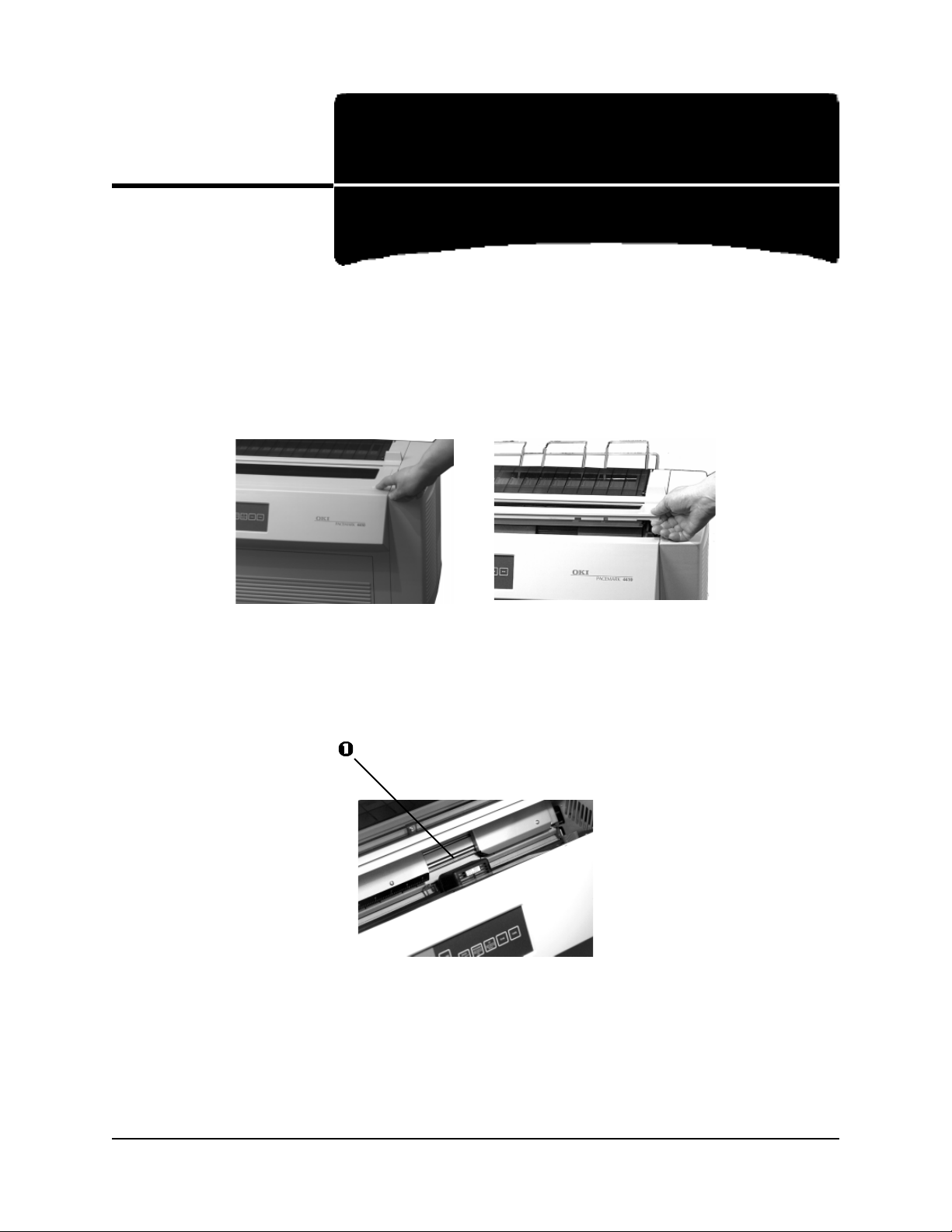
Replacing the Ribbon
Remove the Old Ribbon
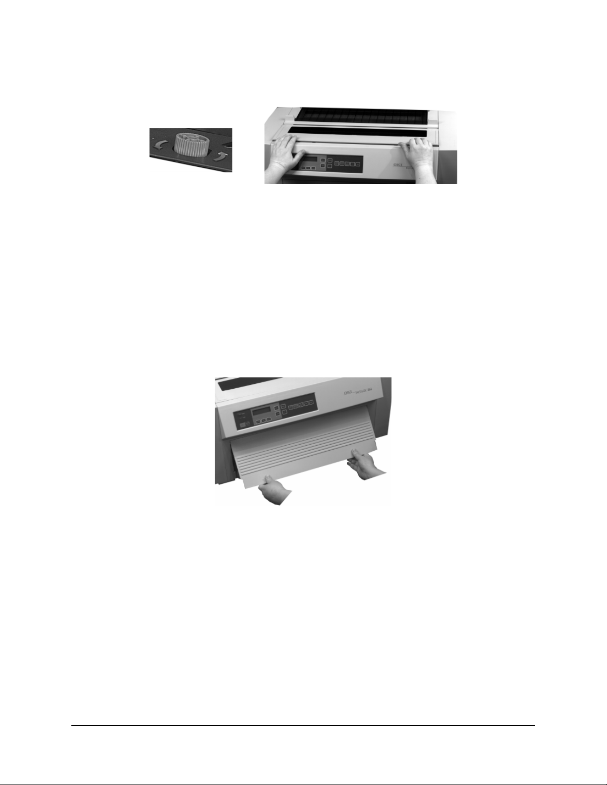
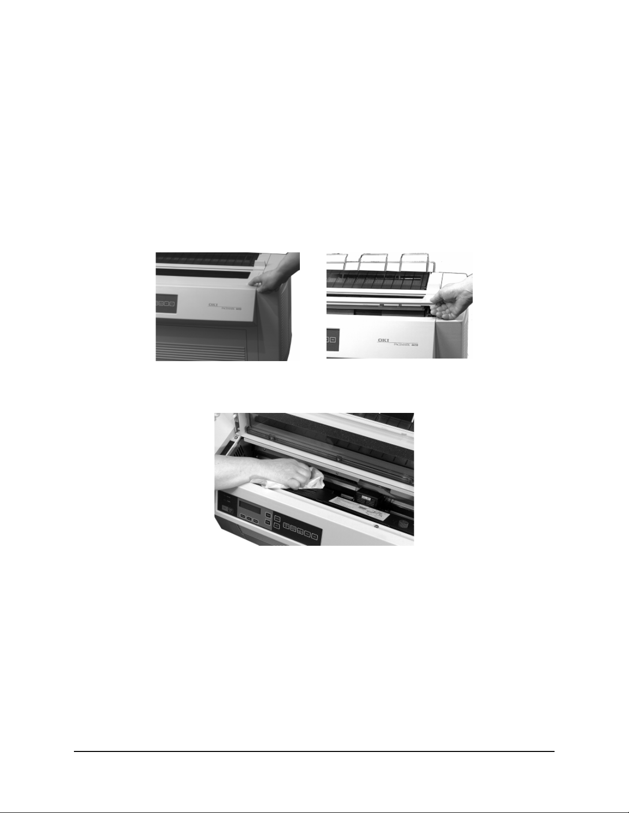
1.Turn the printer off, then press on the area(s) marked PUSH and open the printhead
access cover.
Caution! The printhead may be extremely HOT!
2.Move the printhead to the ribbon loading area (1).
22
Page 23
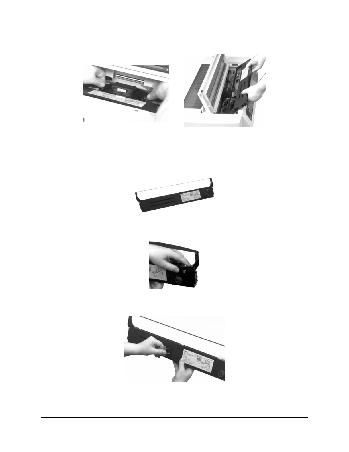
3.Unthread the ribbon from the printhead, then remove and discard the cartridge.
Prepare the New Ribbon
1.Open the new ribbon cartridge and swing out the ribbon arms at either end of the
ribbon cartridge until they snap into place.
2.Push in on the white plastic ribbon restraint at the right end of the cartridge.
3.Pull out the red shipping restraint.
23
Page 24
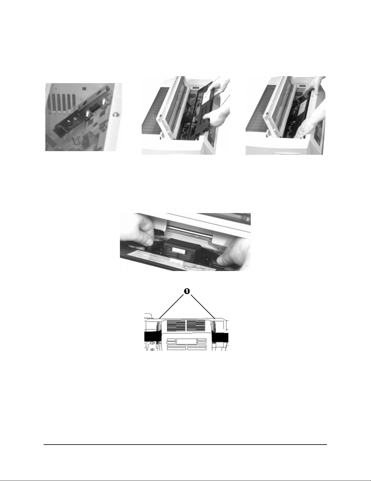
Install the New Ribbon
1.Install the ribbon cartridge in the printer: place the ribbon arms over the metal tabs at
either end, then press down on the cartridge.
2.Feed the ribbon over the back of the printhead, threading it into the black guides (1) on
either side of the printhead.
Caution! Be careful not to twist the ribbon: this can cause jams.
24
Page 25
3.Turn the blue knob counter clockwise (in the direction of the molded arrows) to take up
any slack in the ribbon, then close the printhead access cover.
Caution! Do NOT turn the knob clockwise: this can cause the ribbon to jam!
Clearing Paper Jams
Front Feed Jams
To clear a front feed paper jam:
1.Press PARK to retract the paper from the paper path.
2.Turn the printer off.
3.Pull the front access door out and lift it up into the open position.
25
Page 26
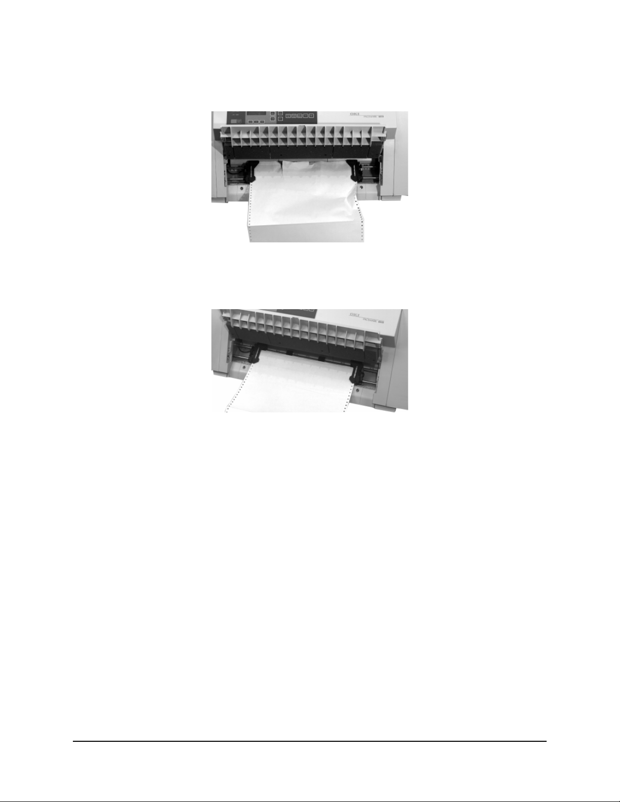
4.Open the tractor pin covers and remove the jammed paper. Be careful to remove any
ripped pieces.
5.Tear off two or three forms to ensure a clean, unwrinkled form, then reload the
continuous forms on the pins and close the tractor pin covers.
6.Close the front access door and turn the printer on.
7.Press FF/LOAD to load the paper into the print path.
If the paper continues to jam...
If you continue to experience paper jams, there are probably some inaccessible pieces
stuck in the paper path. To correct this:
1.Press the
PARK button to retract the paper from the paper path.
2.Open the front access door.
3.Fold some continuous forms paper over three times to form a thick “sheet,” then load
the sheet on the tractors, and press
FF/LOAD. The sheet will feed into the printer,
pulling any loose pieces through the path and out into the printhead area.
4.Remove the pieces, then press
FF/LOAD and remove the thick paper.
5.Reload your regular continuous forms and close the front access door.
6.Press
FF/LOAD.
26
Page 27
Rear Feed Jams
To clear a rear feed paper jam:
1.Press PARK to retract the paper from the paper path.
2.Turn the printer off.
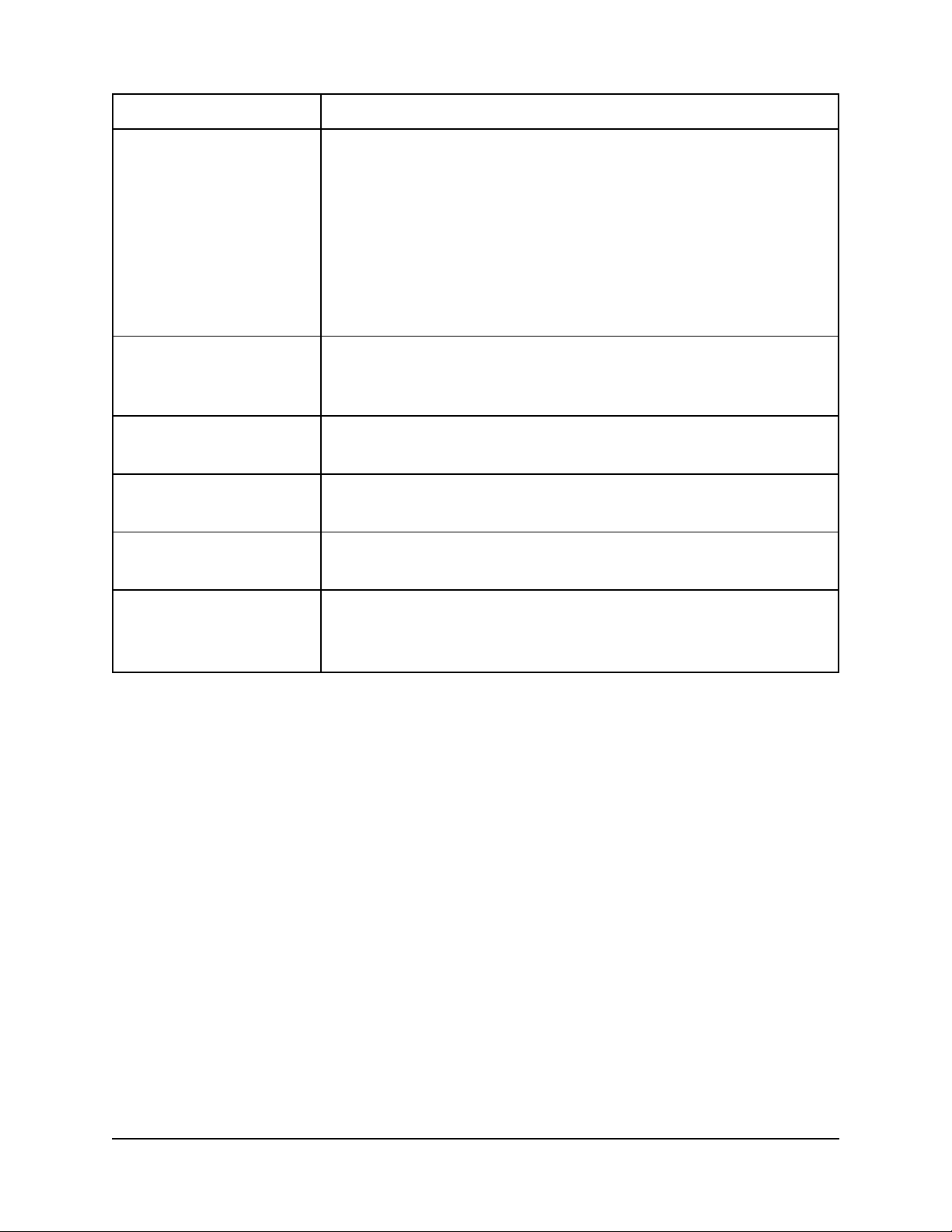
3.Push on the rear-feed access cover tabs and swing the cover back.
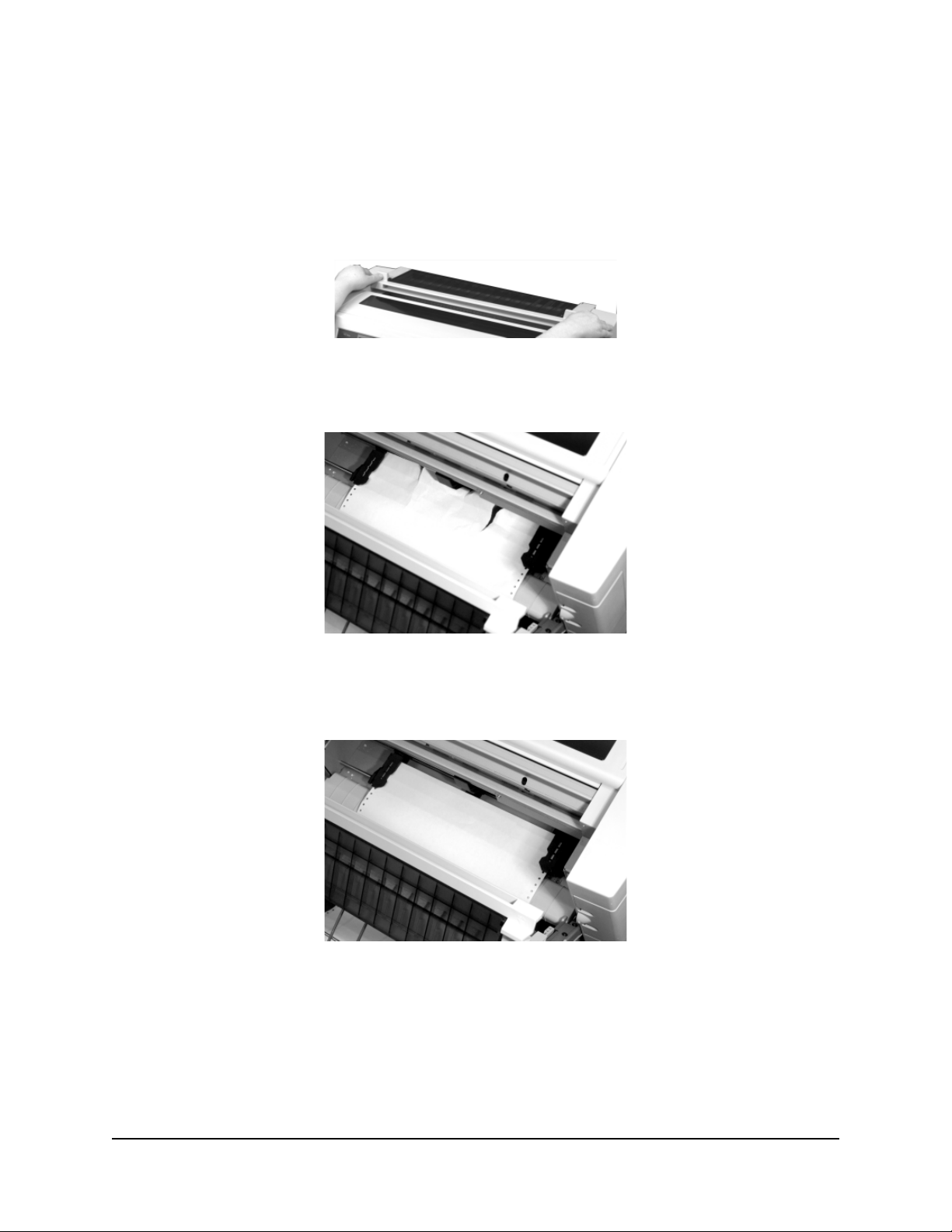
4.Open the tractor covers and remove the jammed paper. Be careful to remove any ripped
pieces.
5.Tear off two or three forms to ensure a clean, unwrinkled form, then reload the
continuous forms on the pins and close the tractor covers.
6.Close the rear-feed access cover and turn the printer on.
7.Press
FF/LOAD to load the paper into the printing path.
27
Page 28
If the paper continues to jam...
If you continue to experience paper jams, there are probably some inaccessible pieces
stuck in the paper path. To correct this:
1.Press the
2.Open the rear-feed access cover.
3.Fold some continuous forms paper over three times to form a thick “sheet,” then load
the sheet on the tractors, and press
pulling any loose pieces through the path and out into the printhead area.
4.Remove the pieces, then press
5.Reload your regular continuous forms and close the rear-feed access cover.
6. Press
PARK button to retract the paper from the paper path.
FF/LOAD. The sheet will feed into the printer,
FF/LOAD and remove the thick paper.
FF/LOAD.
Replacing the Power Fuse
To replace the power fuse:
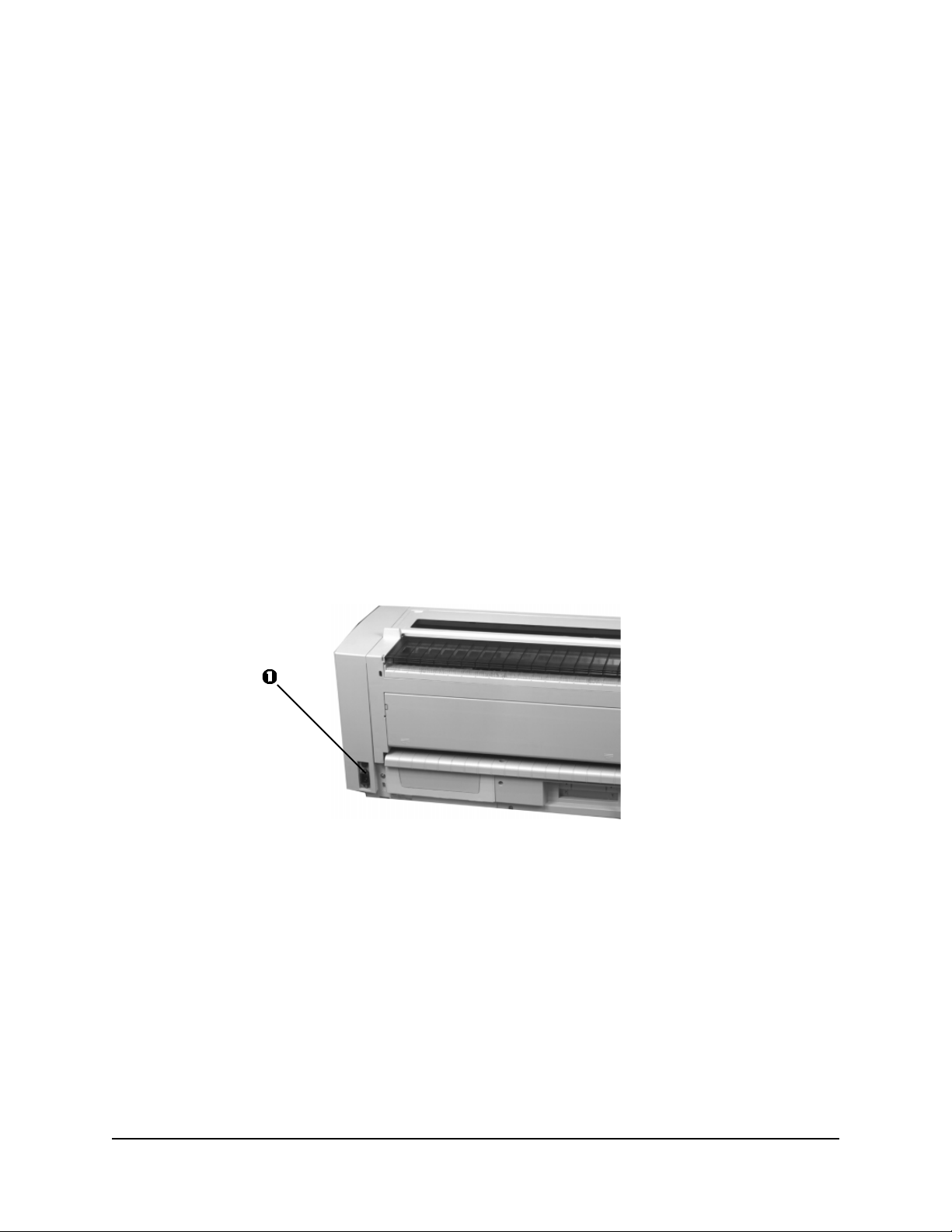
1.Turn the printer off and unplug it from the outlet.
2.Turn the fuse housing (1) to the left and remove it from the printer.
3.Replace the fuse and reinstall the fuse housing in the printer.
4.Plug the printer back in and turn it on.
28
Page 29
Cleaning the Housing
You should clean the housing every few months (or after about 300 hours of operation).
Caution! Never use solvents or strong detergents on the cabinet: they could damage
the housing.
Cleaning the Interior
1.Press
2.Turn the printer off.
3.Press on the area(s) marked PUSH and open the printhead access cover.
PARK to remove the paper from the print path.
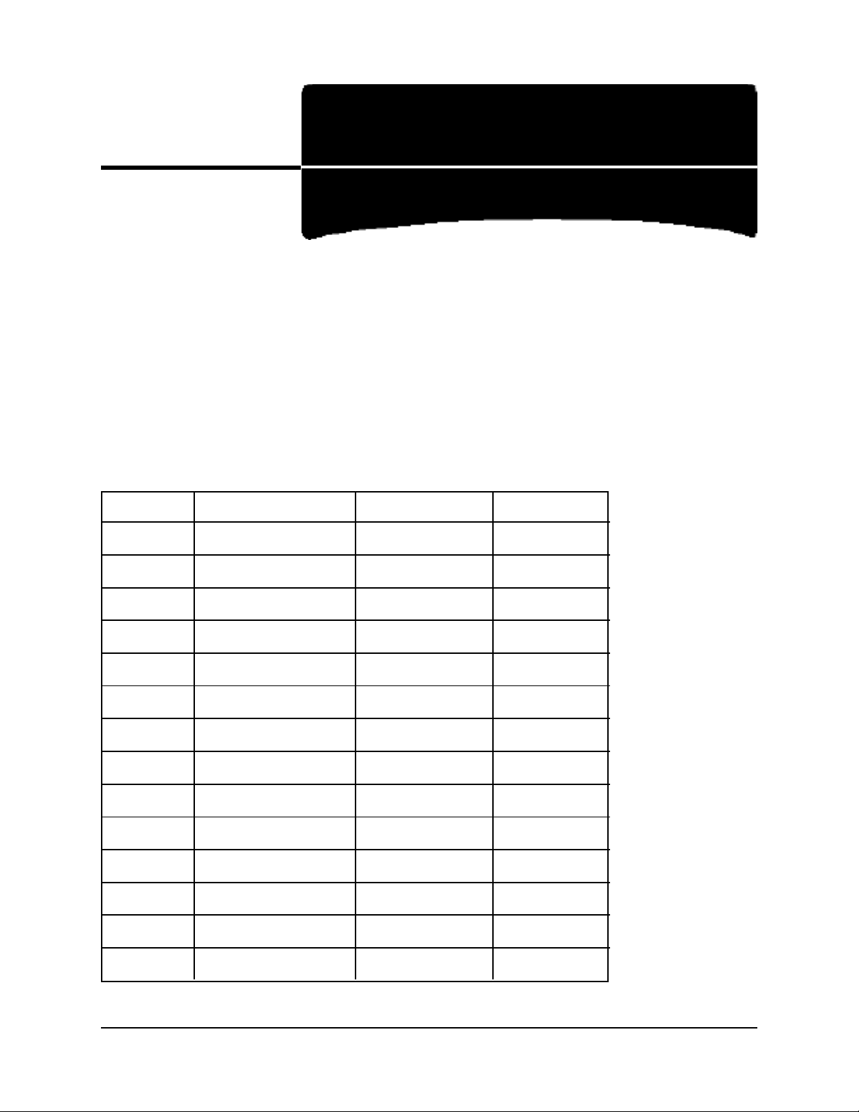
4.Use a clean, dry cloth to dust around inside the printer. Remove any loose bits of paper.
29
Page 30

5.Close the printhead access cover.
6.Pull out the front access cover and lift it into the open position.
7.Vacuum out any paper dust and loose bits of paper, then close the cover.
8.Open the rear-feed access cover and vacuum out any paper dust and loose bits of paper,
then close the cover.
9.Turn the printer back on and press FF/LOAD to load paper back into the print path.
Cleaning the Exterior
Use a damp cloth with a mild detergent to wipe the printer’s external housing clean.
30
Page 31

3: Troubleshooting
General Troubleshooting
Problem:
Nothing happens when I turn on the printer.
Solutions:
1.Check the power cord connection to the outlet.
2.If you are using a power strip, make sure it is turned on and that the fuse has not blown
nor the circuit breaker tripped.
3.Check the fuse (1) at the back of the printer:
Problem:
The printer does not print when the computer sends data.
Solutions:
1.Is the Status light on? If not, press
2.Check that the interface cable is securely connected to both the printer and to the
computer or network.
3.If you have the optional accessory card installed, make sure it is firmly seated in the
printer.
ON-LINE/RESET.
31
Page 32

Problem:
I’m getting strange symbols, incorrect fonts, etc.
Solution:
1.Check to be sure that the printer driver you have selected in your software matches the
printer emulation.
2.If you have embedded any printer commands in your software, check to be sure that
you entered them correctly.
Problem:
The MENU, GROUP, ITEM, OPTION and STORE buttons on the front panel won’t work.
Solution:
The Op. Panel Function in the printer menu can be used to disable these buttons. If the
printer is part of a customized system or if it is used by a number of people, the system
manager may have used this option to make sure the printer is always set properly.
Problem:
The files I send do not print the way I have the menu and front panel set.
Solution:
Before sending a file to the printer, the software may be sending either an “initialization
string” or an I-Prime signal to the printer.
The initialization string contains codes that override the panel and menu settings. To
change the printer to ignore the reset code, press MENU to enter the menu mode, go to
the Set-Up group and change the setting for the Reset Inhibit item to Yes (see Section 1
for more information on changing menu settings).
The I-Prime signal will automatically override any front panel settings you have made. To
eliminate this problem, press MENU to enter the menu mode, go to the Parallel I/F group
and change the setting for I-Prime to Invalid (see Section 1 for more information on
changing menu settings).
32
Page 33

Problem:
I am continuing to have paper exit jams.
Solution:
If you are using front feed, make sure that the front of the printer is flush with the edge of
the table.
If you are using rear feed, make sure that the rear of the printer is flush with the edge of
the table.
If you are switching paper paths on a regular basis, use a table/support for the printer
which is close to the front-to-back depth of the printer so that both the front and rear of
the printer can be placed flush with the edge of the support.
Problem:
The front access door won’t close properly.
Solution:
Make sure that the front-feed tractor covers are properly closed.
33
Page 34

Problem:
I’m trying to print envelopes, but they keep jamming.
Solution:
If you load continuous-form envelopes at the default position, the auto gap thickness is
sensed at the envelope’s flap position which is thinner than the envelope’s main area. This
can cause jamming when the envelopes are being printed.
The auto gap needs to be set at the thicker area of the envelope. To do this:
1.Press
2.Hold
3.Press
4.Press
FF/LOAD to load the envelope forms into the print path.
SHIFT and press FF/LOAD/Micro Feed Up until the bail closes.
PARK to remove the envelopes from the print path.
FF/LOAD.
5.Send one address to start the printhead moving so that the gap is automatically set for
the double thickness area of the envelope.
6.Press
7.Hold
8.Press
PARK to remove the envelopes from the print path.
SHIFT and press PATH/TOF to reset the Top of Form to the factory setting.
FF/LOAD to load the envelopes back into the print path.
Error Messages
Error Message What to Do
AUTO GAP Printhead gap malfunction. Try turning the printer of f, then on
again. If message persists, contact your service provider (see
Section 4).
BAIL Bail motor not functioning properly. Try turning the printer off,
then on again. If message persists, contact your service provider
(see Section 4).
CENTERING Spacing error during centering operation. Try turning the printer
off, then on again. If message persists, contact your service
provider (see Section 4).
CG-ROM Try turning the printer off, then on again. If message persists,
contact your service provider (see Section 4).
COVER OPEN Printhead access cover is open. Close it.
D-RAM Try turning the printer off, then on again. If message persists,
contact your service provider (see Section 4).
34
Page 35

Error Message What to Do
DATA REMAIN Data is being held in the buffer due to the fact that the printhead
cover is open. Close the cover, then press ON-LINE/RESET.
EEPROM Try turning the printer off, then on again. If message persists,
contact your service provider (see Section 4).
EJECT JAM Paper jammed as it was being ejected. Correct the jam and
reload paper.
FEED JAM Paper jammed during a print job as it was feeding through the
printer. Clear the paper jam (see Section 2) and reload paper.
FUSE Internal fuse has blown. Contact your service provider (see
Section 4).
HEAD 1 FAN Printhead Fan 1 is damaged. Contact your service provider (see
Section 4).
HEAD 2 FAN Printhead Fan 2 is damaged. Contact your service provider (see
Section 4).
HEAD THERMAL Printhead has overheated. Turn the printer off and wait for the
printhead to cool down, then try again. If the message persists,
contact your service provider (see Section 4).
HEAD THERMISTOR Printhead thermistor is damaged. Contact your service provider
(see Section 4).
HOMING Try turning the printer off, then on again. If message persists,
contact your service provider (see Section 4).
INVALID IPT Illegal IPT alarm. Try turning the printer off, then on again. If
message persists, contact your service provider (see Section 4).
LCD TIME OUT Try turning the printer off, then on again. If message persists,
contact your service provider (see Section 4).
LF THERMAL The line feed motor has overheated. Turn the printer off and wait
for it to cool down, then try again. If the message persists,
contact your service provider (see Section 4)
LOAD JAM Paper jammed as it was being loaded into the print path. Press
PARK to remove the paper from the print path, then clear the
paper jam (see Section 2) and reload paper.
MAIN LSI Try turning the printer off, then on again. If message persists,
contact your service provider (see Section 4).
OFF-LINE Printer is off line (ALARM light on). Press ON-LINE/RESET
when you are ready to place the printer back on line.
35
Page 36

Error Message What to Do
OKI HSP CONNECT There is a problem with the OKI HSP connection. Check to be
sure that the print server is properly installed and that the
connection is secure. If message persists, contact your service
provider (see Section 4).
OPT CARD ROM There is a problem with the ROM on the optional interface card.
Try turning the printer off, then on again. If message persists,
contact your service provider (see Section 4).
OPT CARD CONNECT There is a problem with the connection to the optional interface
card. Check to make sure that the card is properly installed and
that the connection is firm, then try turning the printer off, then
on again. If message persists, contact your service provider (see
Section 4).
OPTICAL SENSOR Paper width sensor alarm. Try turning the printer off, then on
again. If message persists, contact your service provider (see
Section 4).
PAPER END Paper has run out. Load a new stack of continuous forms.
PAPER JAM Paper edge has ripped and caused a jam. Clear the paper jam
(see Section 2) and reload paper .
PAPER RELEASE The bail is partially open. Press SHIFT + PARK.
PARK JAM Paper jammed as it was being parked. Clear the paper jam (see
Section 2) and reload paper.
PA TH CHANGE Path switching motor is not functioning properly. Contact your
service provider (see Section 4).
PA TH CHANGE JAM Paper jam during change in paper path.
* 1. Check to be sure that paper is loaded in both paths.
* 2. Determine which path is jammed, then clear the jam and
reload paper.
POWER FAN Power supply fan malfunction. Contact your service provider
(see Section 4).
PROGRAM-ROM Try turning the printer off, then on again. If message persists,
contact your service provider (see Section 4).
RIBBON Ribbon motor not functioning properly . Try turning the printer
off, then on again. If message persists, contact your service
provider (see Section 4).
36
Page 37
Error Message What to Do
RIBBON JAM 1. Check to be sure that the ribbon is not twisted: open the
printhead access cover, remove the ribbon from around the
printhead and reload it around the printhead and guides,
making sure that it does not get twisted as you load it.
2. Remove the ribbon from the printer, turn the take-up knob
counter clockwise (in the direction of the molded-on arrows) a
few times, then re-install it (see Section 2).
3. If this does not clear the problem, try installing a new ribbon.
SP THERMAL The spacing motor has overheated. Turn the printer of f and wait
for it to cool down, then try again. If the message persists,
contact your service provider (see Section 4)
SPACE FAN Spacing motor fan malfunction. Contact your service provider
(see Section 4).
SPACING Try turning the printer off, then on again. If message persists,
contact your service provider (see Section 4).
S-RAM Try turning the printer off, then on again. If message persists,
contact your service provider (see Section 4).
WDT Watch dog time-out alarm. T ry turning the printer of f, then on
again. If message persists, contact your service provider (see
Section 4).
37
Page 38

4: Service Information
Getting Service & Support
Note: For the latest information on getting service and support, consult our multilingual
web site (English, French, Spanish, Portuguese): http://www.okidata.com
Your Dealer
Consult the store where you purchased your printer, or in the U.S. and Canada, call 1800-OKIDATA (1-800-654-3282) for the location of the nearest Authorized Okidata
Service Dealer. Have your ZIP code ready.
• Proof of purchase is required for warranty work. Be sure to retain your purchase
documents.
Okidata Information System Automated Attendant
1-800-OKI-DATA (1-800-654-3282)
U.S and Canada only.
For automated customer support information, call 1-800-OKI-DATA (1-800-654-3282).
The Okidata Information System Automated Attendant is available 24 hours a day, seven
days a week, and can provide immediate assistance with:
• Sales and service referrals
• Parts and supplies referrals
• Product information
• Access to Faxable Facts retrieval system
1-800-OKI-DATA (1-800-654-3282) also provides access to our Okidata Customer
Support Professionals.
38
Page 39

Okidata Customer Support Professionals
1-800-OKI-DATA (1-800-654-3282)
U.S and Canada only.
Our Customer Support staff is available 24 hours a day, 7 days a week. Please be sure that
you are calling from a telephone close to your printer so you can describe your problem
accurately.
Our Customer Support Professionals are trained on all current OKI products. They can
answer your questions regarding:
• Locations of Sales & Service Dealers
• Installation of your OKI printer
• Usage/normal maintenance of your printer
• Availability/installation of printer drivers
• Error message interpretation/solutions
• Parts and Supplies identification
• Consumer relations
Note: Customer Support Professionals are not trained to provide assistance with the use
of commercial software packages. Please consult your software users manual for
times and availability of the manufacturers support.
39
Page 40

Okidata Service Locations
If repair to your printer becomes necessary, the repair can be handled by one of Okidata’s
many repair facilities.
In the U.S. and Canada
Before shipping your printer, call 1-800-OKI-DATA (1-800-654-3282) for a return
authorization number. Select the “service” option to find an appropriate service depot.
After receiving your return authorization number, you will be given directions for
shipping your product to one of our repair facilities.
• Allow 10 days for round trip shipping repair via a depot.
• Carry-in repairs must be called in first to schedule service.
In Latin America
Before shipping your printer, call one of the service centers listed below. For a complete
listing of all available service centers in Latin America, consult the Spanish and
Portuguese sections of our multilingual web site at http://www.okidata.com.
Service Location Listings
United States Canada
Oki Data Americas, Inc. Oki Data Americas, Inc.
Phone 1-800-654-3282 Phone 1-800-654-3282
Fax 1-609-222-5247 Fax 1-905-238-4427
Brazil Mexico
Oki Data do Brasil, Ltda. Oki Data de mexico, S.A. de C.V.
Phone (5511) 5589-1518 Phone 525-661-6860
Fax (5511) 5584-0267 Fax 525-661-5861
40
Page 41

Purchasing Replacement Parts & Accessories
Before you order, know your printer model number (Pacemark 4410) and have the correct
part number and description of the item
Ways to Purchase
• Consult the dealer where you purchased your printer
• Consult an Okidata Authorized Sales or Service Dealer.
In the U.S. and Canada, call 1-800-OKIDATA (1-800-654-3282) for the nearest
Authorized Sales and Service location. Have your ZIP code ready for our Customer
Support Representatives.
• In the U.S., order toll-free by phone at 1-800-OKIDATA (1-800-654-3282), using
VISA
®
, MasterCard®, or American Express®.
• In Canada, call 905-602-6400 to order parts: VISA and American Express are accepted.
• Check office supply catalogs or your local stationery store. Most carry Okidata brand
ribbons. Be sure to ask for genuine Okidata ribbons!
41
Page 42

Accessories
Note: For the latest available accessories for the Pacemark 4410 printer, check our web
site —
OkiLAN® Model 6100e Ethernet® Network Interface Card, P/N 70034201
http://www.okidata.com.
For Pacemark 4410 non-network version only. Installs in the network/option slot to
convert the printer for use in network environments.
OKI Adapter Card
For Pacemark 4410 non-network version only. This card installs in the network/option
slot to allow use with third-party options such as Twinax/Coax boards. For more
information, check our web site — http://www.okidata.com — or call
1-800-OKI-DATA (1-800-654-3282).
Replacement Parts
Fuse, 120 volt ...............................Order # 56305901
Paper Guide
..................................................Order # 40658201
Power Cords
120 volt .....................................Order # 56631801
220 volt .....................................Order # 56631901
Printhead Access Cover
..................................................Order # 40520201
Ribbon Cartridge
..................................................Order # 40629302
42
Page 43

Tear Bar Cover
..................................................Order # 40519801
43
Page 44

A: Specifications
General Specifications
Print Method: Serial impact dot matrix
Printhead: Two rows of nine pins in a single-head diamond configuration
Graphics Resolution (Maximum)
Microline Standard Mode: 288 dpi horizontal x 144 dpi vertical
Epson/IBM Modes: 240 dpi horizontal x 216 dpi vertical
Print Speed
Mode Characters per Inch Speed , Characters per Second
HSD (High Speed Draft) 10 cpi 1066 cps
12 cpi 1066 cps
15 cpi 1066 cps
17.1 cpi 1066 cps
20 cpi 1066 cps
Utility 10 cpi 800 cps
12 cpi 800 cps
15 cpi 800 cps
17.1 cpi 800 cps
20 cpi 800 cps
NLQ (Near Letter Quality) 10 cpi 200 cps
12 cpi 200 cps
15 cpi 200 cps
17.1 cpi 200 cps
20 cpi 200 cps
44
Page 45

Characters per Line
Setting, Characters per Inch Characters per Line
10 cpi 136 cpl
12 cpi 163 cpl
15 cpi 204 cpl
17.1 cpi 233 cpl
20 cpi 272 cpl
Emulations: Epson FX, IBM Proprinter III, Okidata Microline Standard
Interface
Model 4410
Standard: Centronics parallel IEEE-1284, Nibble Mode
RS-232C 25-pin Serial, 38.4 KBps maximum baud rate
Optional: OkiLAN 6100e EtherNet
®
Network Print Server
Model 4410 Network Ready
Standard: Centronics parallel IEEE-1284, Nibble Mode
RS-232C 25-pin Serial, 38.4 KBps maximum baud rate
OkiLAN 6100e EtherNet
®
Network Print Server
Font Specifications
Mode/Type Available Fonts
NLQ (Near Letter Quality) Courier, Gothic
Utility Gothic
HSD (High Speed Draft) Gothic
Scalable Fonts (22 to 216 point) Courier, Gothic
Bar Code Fonts Code 39, UPC A, UPC E, EAN 8, EAN 13,
Interleaved 2 of 5, Code 128, PostNet
45
Page 46

Reliability
Parameter Reliability
Mean Time Between Failures (MTBF) 15,000 hours at 25% duty cycle and
35% page density
Mean Time to Repair (MTTR) 15 minutes, major subassembly level
Printhead Life 400 million characters average in 10 cpi utility
mode at 25% density and 35% page density
Ribbon Life (on average, 10 cpi utility) 15 million characters
Paper Specifications
Front Feed
Maximum thickness: 0.031 inches (0.79 mm)
Type Weight Thickness Width
Single Part 12 to 24 lb. 0.031 inch 3* to 16½ inches
(45 to 90 g/m2) (0.79 mm) (76 to 419 mm)
Carbonless (1 + 9 max.)** 9 to 11 lb. 0.031 inch 3* to 16½ inches
(34 to 40 g/m2) (0.79 mm) (76 to 419 mm)
Interleaf (1 + 6 max) 9 to 14 lb. paper 0.031 inch 3* to 16½ inches
(34 to 52 g/m2) (0.79 mm) (76 to 419 mm)
9 lb. carbon (34 g/m2)
Labels N.A. 0.011 inch 3¼ to 15 inches
(0.28 mm) (83 to 381 mm)
Envelopes 24 lb. (90 g/m2) max. 0.014 inch 3 to 10 inches
(0.36 mm) (76 to 254 mm)
Card Stock 100 lb. (375 g/m2) max. 0.008 inch 3 to 8 inches
(0.20 mm) (76 to 203 mm)
* For paper widths less than 5 inches (127 mm), remove the support between the tractors.
** When using forms thicker than 7-part carbonless or its equivalent, you must enter the Menu
mode, then go to the Impact Mode item in the Set-Up group and select High-Impact Copy
as the setting.
46
Page 47

Rear Feed
Maximum thickness: 0.014 inches (0.36 mm)
Type Weight Thickness Width
Single Part 12 to 24 lb. 0.014 inches 3* to 16½inches
(45 to 90 g/m2) (0.36 mm) (76 to 419 mm)
Carbonless (1 + 5 max.) 9 to 11 lb. 0.014 inches 3* to 16½ inches
(34 to 40 g/m2) (0.36 mm) (76 to 419 mm)
Interleaf (1 + 3 max) 9 to 14 lb. paper 0.014 inches 3* to 16½ inches
(34 to 52 g/m2) (0.36 mm) (76 to 419 mm)
9 lb. carbon (34 g/m2)
* For paper widths less than 5 inches (127 mm), remove the support between the tractors.
Physical Specifications
Dimensions
Width: 30¼ inches (768 mm)
Depth: 15-5/32 inches (385 mm)
Height: 14-7/8 inches (378 mm)
Weight: 92.6 lbs (42 kg)
Environmental Specifications
Temperature
Operating: 41 to 95°F (5 to 35°C)
Storage: 14 to 109°F (-10 to +43°C)
Relative Humidity
Operating: 20 to 80%RH (Maximum wet bulb temperature 30°C)
Storage: 5 to 95%RH (Maximum wet bulb temperature 40°C)
47
Page 48

Electrical Specifications
Voltage: 90 to 264 Volts, AC, universal
Frequency: 50 or 60 Hz, ±2%
Power Consumption
Idling: Less than 15 watts
Local Test: About 295 watts
Memory
ROM: two x 512 KB EPROM
RAM:
Resident: 512KB
Receive Buffer Size: 28KB maximum (56KB maximum, no DLL)
DLL: 27.75KB maximum (NLQ = 2 x 12KB; UTL = 3.25K)
48
Page 49
B: Interfacing
Parallel Interface
The parallel interface is standard IEEE 1284 bi-directional with a 36-pin, Amphenol
57-40360-12-D56 receptacle. It requires a Centronics-equivalent parallel cable with the
following:
• Amphenol 57-30360 or AMP 552274-1 plug (or equivalent) with 36 pins
• AMP 552073--1 (or equivalent) cover
• UL and CSA approved shielded cable, maximum 6 feet, with twisted pair conductors.
Parallel Interface Pin Assignments
Pin No. Signal Return Pin Direction
1 Data Strobe 19 To printer
2 Data Bit 1 20 To printer
3 Data Bit 2 21 To printer
4 Data Bit 3 22 To printer
5 Data Bit 4 23 To printer
6 Data Bit 5 24 To printer
7 Data Bit 6 25 To printer
8 Data Bit 7 26 To printer
9 Data Bit 8 27 To printer
10 Acknowledge 28 From printer
11 Busy 29 From printer
12 Paper End 30 From printer
13 Select No return From printer
14 Auto Feed To printer
49
Page 50

15 Unused - 16 0V No Return 17 Chassis Ground No Return 18 +5V - From printer
19 to 30 0V - 31 I-Prime - To printer
32 Fault - From printer
33 0V - 34 Unused - 35 - - 36 Select-I - To printer
50
Page 51

Serial Interface
The serial interface is EIA Standard RS-232C serial input, start-stop synchronization.
• Baud Rate: 300, 600, 1200, 2400, 4800, 9600 (default), 19,200, or 38,400 bps
• Data Word Length: 7 (default) or 8 bits
• Parity: None (default), odd, even
• Stop Bit Length: 1 bit or more
• Message Buffer Length: 8,192 bytes
• Communication Protocol: Ready/Busy (default) or X-ON/X-OFF
Serial Interface Pin Assignments
Pin No. Signal Symbol Direction
1 Protective Ground PG 2 Transmitted Data TD From printer
3 Received Data RD To printer
4 Request to Send RTS From printer
5 Unused - 6 Data Set Ready DSR To printer
7 Signal Ground SG 8 to 10 Unused - 11 Supervisory Send Data SSD From printer
12 to 19 Unused - 20 Data T erminal Ready DTR From printer
21 to 25 Unused - -
51
Page 52

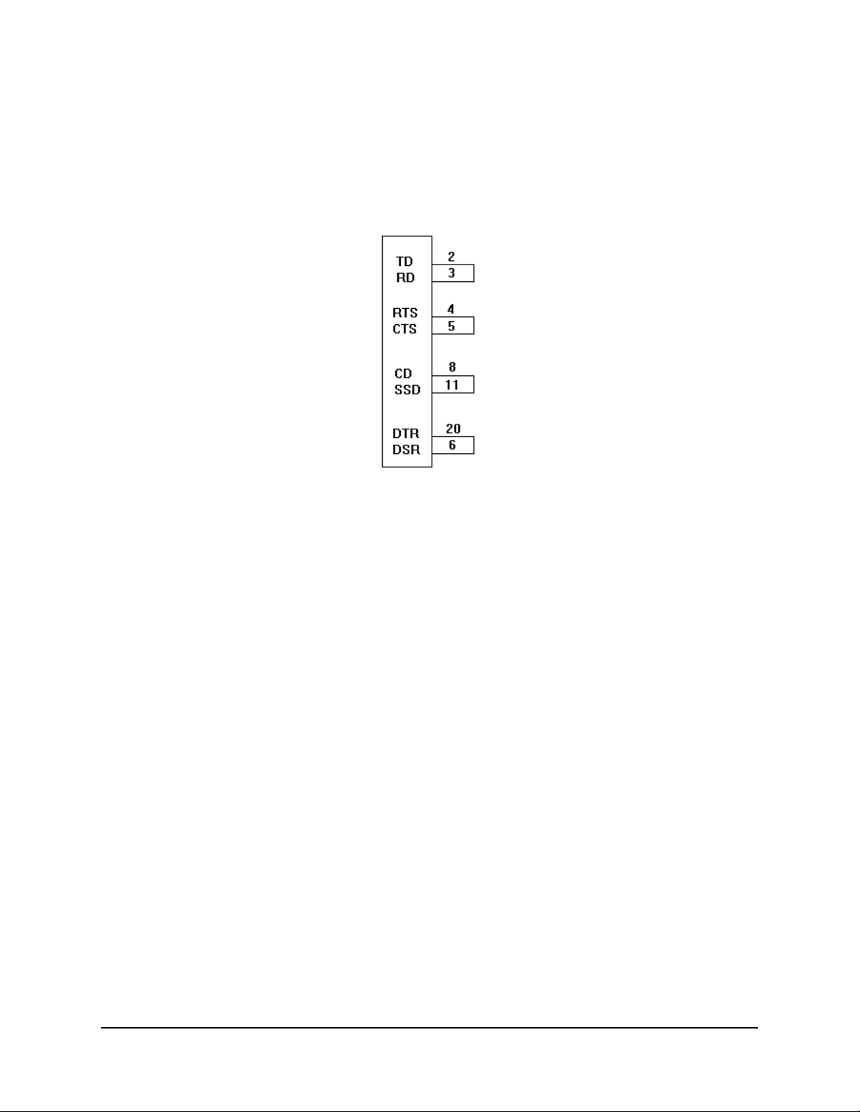
Commonly Used Serial Cable Configurations
IBM 25-Pin Cable Configuration
Computer Printer
PG1 ______________ 1 PG
TD2 ______________ 3 RD
RD 3 ______________ 2 TD
CTS 5 ______________ 11 SSD
DSR 6 ______________ 20 DTR
6 DSR
SG 7 ______________ 7 SG
4 RTS
5 CTS
IBM 9-Pin Cable Configuration
Computer Printer
RD 2 ______________ 2 TD
TD 3 ______________ 3 RD
SG 5 ______________ 7 SG
DSR 6 ______________ 20 DTR
6 DSR
CTS 8 ______________ 11 SSD
4 RTS
5 CTS
52
Page 53
Serial Interface Test
To perform a local diagnostic test of the serial interface:
Note: To stop the test at any time, turn the printer off.
You need a test connector to jumper the following pins:
1.Enter the printer menu and change the Diagnostic Test item in the Serial I/F group to
Yes.
2.Turn the printer off.
3.Plug the test connector into the serial interface receptacle.
4.Turn the printer on:
• The printer prints the message “LOOP TEST”
• The printer checks the memory function of the message buffer, then prints “RAM
GOOD” if the memory check is okay, or “RAM BAD” if the memory check fails.
• The signal logic is checked. If the signal logic is okay, “I/F GOOD” prints. If it is
faulty, “I/F BAD” prints.
• Hexadecimal characters from 20 to 7E are transmitted through the TD (Transmit
Data) line, and received through the RD (Receive Data) line, then written to the
message buffer. The above stored data is then printed.
• This process repeats until the printer is turned off.
5.Turn the printer off, then press and hold
MENU while turning the printer back on.
This ends the test and places you in the Menu mode.
6.Go to the Serial I/F group and change Diagnostic Test back to No.
7.Press
STORE to save the setting, then press MENU to exit the Menu mode.
53
Page 54

Ethernet® 10/100 BaseT Interface
The print server has an Ethernet 10/100 BaseT interface with an RJ45 receptacle and a
parallel interface for interconnection with the printer.
The interface is supplied with a short cable for connection of the parallel interface.
Note: The Ethernet port requires a 10/100 BaseT cable with two twisted-wire pairs.
Ethernet 10/100 BaseT Interface
Pin Assignments
Pin No. Signal Description
1 TD+ Transmit Data +
2 TD- Transmit Data 3 RD+ Receive Data +
4 Not Used 5 Not used 6 RD- Receive Data
7, 8 Not Used -
54
Page 55

Print Server Parallel Output Pin Assignments
Pin No. Signal Source Description
1 nSTROBE Print Server Indicates when the data on the data
lines is valid.
2-9 DATA 1-8 Print Server Eight lines used for data transfer.
10 nACK Printer Data acknowledge signal.
11 BUSY Printer Indicates the printer is not ready to
receive data.
12 PAPER ERROR Printer Indicates a paper error.
13 SELECT Printer Indicates the printer is online.
14 nAUTOFEED Print Server Used for IEEE-1284 compliance.
15 nFAULT Printer Indicates a printer error condition.
16 nINIT Print Server Instructs the printer to initialize.
17 nSELECT IN Print Server Used for IEEE-1284 compliance.
18-25 GND - Ground
55
Page 56

C: Command Summary
Epson FX Command Summary
Epson Command ASCII Hexadecimal Decimal
Printer Operation/Data Control
Configuration Group
Select CFG1 ESC DLE J P1 1B 10 4A P1 01 27 16 74 P1 1
P1 = 0: command valid SOH
P1 = 1: command invalid
Select CFG2 ESC DLE J P1 1B 10 4A P1 02 27 16 74 P1 2
P1 = 0: command valid STX
P1 = 1: command invalid
Delete DEL 7F 128
Emulation Mode, Select
Epson FX ESC { @ 1B 7B 40 27 123 64
IBM Proprinter ESC { NUL 1B 7B 00 27 123 0
OKI Microline Standard ESC { ! 1B 7B 21 27 123 33
MSB Control
Cancel MSB control ESC # 1B 23 27 35
Set MSB equal to 0 ESC = 1B 3D 27 61
Set MSB equal to 1 ESC > 1B 3E 27 62
Paper-Out Sensor
Disable ESC 8 1B 38 27 56
Enable ESC 9 1B 39 27 57
56
Page 57
Epson Command ASCII Hexadecimal Decimal
Printer Operation/Data Control (continued)
Paper Path, Change to
Rear Path
P1 represents the number ESC DLE I P1 0 1B 10 49 P1 30 27 16 73 P1 48
of bytes of data
Front Path
P1 represents the number ESC DLE I P1 1 1B 10 49 P1 31 27 16 73 P1 49
of bytes of data
Print Direction
Unidirectional ESC U 1 1B 55 31 27 85 49
Bidirectional ESC U 0 1B 55 30 27 85 48
Unidirectional for one line ESC < 1B 3C 27 60
Print Speed, Half
On ESC s 1 1B 73 31 27 115 49
Off ESC s 0 1B 73 30 27 115 48
Print Suppress
On DC3 13 19
Off DC1 11 17
Reset
Clear Print Buffer ESC @ 1B 40 27 64
Clear Buffer and CAN 18 24
Initialize Printer
Select Menu Item
See the end of this ESC DLE D Pno P
Appendix for details Pb1 Pa2 Pb2...Pan P
1B 10 44 Pno P
a1
Pb1 Pa2 Pb2...Pan P
bn
27 16 68 Pno P
a1
bn
Pb1 Pa2 Pb2...Pan P
on this command.
Software I-Prime ESC } 1B 7D 27 125
Vertical Control
Form Feed, Execute FF 0C 12
Form Length
Set in inches, n = 0 or 128 ESC C NUL n 1B 43 00 n 27 67 0 n
Set in lines, n = 1 to 127 ESC C n 1B 43 n 27 67 n
a1
bn
57
Page 58

Epson Command ASCII Hexadecimal Decimal
Vertical Control (continued)
Line Feed
n/144 inch, n = 0 to 255 ESC % 5 n 1B 25 35 n 27 37 53 n
n/216 inch, n = 0 to 255 ESC J n 1B 4A n 27 74 n
Forward LF with CR LF 0A 10
Reverse LF, n = 0 to 255 ESC j n 1B 6A n 27 106 n
Line Spacing
n/72-inch increments ESC A n 1B 41 n 27 65 n
n = 0 to 85, 128 to 213
n/144-inch increments ESC % 9 n 1B 25 39 n 27 37 57 n
n = 1 to 255
n/216-inch increments, ESC 3 n 1B 33 n 27 51 n
n = 0 to 255
1/6-inch ESC 2 1B 32 27 50
1/8-inch ESC 0 1B 30 27 48
7/72-inch ESC 1 1B 31 27 49
Margins, Bottom
(Auto Skip)
Cancel ESC O 1B 4F 27 79
Define, n = 0 to 127 lines ESC N n 1B 4E n 27 78 n
Vertical Tabs
Execute VT 0B 11
Define tab stops ESC B n1 n2...n
k
1B 42 n1 n2...n
k
27 66 n1 n2...n
n = 1 to 255 NUL 00 0
k = 1 to 16
Define tab stops in ESC b n m
1
1B 62 n m
1
27 98 n m
channels m2...mk NUL m2...mk 00 m2...mk 0
m = 0 to 255
n = 0 to 7
Select channel ESC / n 1B 2F n 27 47 n
n = 0 to 7, 128 to 135
k
1
58
Page 59

Epson Command ASCII Hexadecimal Decimal
Horizontal Control
Backspace BS 08 8
Carriage Return CR 0D 13
Horizontal Tabs
Execute HT 09 9
Set, up to 32 tabs ESC D x1 x2 x3...x
1B 44 x1 x2 x3...x
k
27 68 x1 x2 x3...x
k
x = 1 to 255 NUL 00 0
k = 1 to 32
Margins, Set by character
columns
Set left margin ESC l n 1B 6C n 27 108 n
Pitch Range for n
10 cpi 1 to 134
12 cpi 1 to 162
15 cpi 1 to 202
17.1 cpi 1 to 231
20 cpi 1 to 255
Set right margin ESC Q n 1B 51 n 27 81 n
Pitch Range for n
10 cpi 2 to 136
12 cpi 3 to 164
15 cpi 3 to 204
17.1 cpi 4 to 234
20 cpi 4 to 255
k
59
Page 60

Epson Command ASCII Hexadecimal Decimal
Horizontal Control (continued)
Print Position
Define position by dot ESC \ n1 n
2
1B 5C n1 n
2
columns, indexed from
present position.
Dot position =
n1 + (n2 x 256)
n1 = 0 to 255
n2 = 0 to 255
Execute print position ESC $ n1 n
2
1B 24 n1 n
2
from current left margin
Dot position =
[n1 + (n2 x 256)]/60
n1 = 0 to 255
n2 = 0 to 255
Set print position ESC DLE @ n A1 A21B 10 40 n A1 A
n = 0 to 255: # of bytes P1 P2 P3 P
4
P1 P2 P3 P
4
to follow
A1 = 0 to 255: even,
print position absolute
from left edge; odd,
print position relative
to current position
27 92 n1 n
27 36 n1 n
27 16 64 n A1 A
2
P1 P2 P3 P
2
2
2
4
A2 = 0 to 255: even,
toward right margin
(forward); odd, toward
left margin (reverse)
P1P2P3P4 = 0000 to
9999 ASCII
Print Style/Print Size Control
Character Pitch
Select 10 cpi ESC P 1B 50 27 80
Select 12 cpi ESC M 1B 4D 27 77
Condensed (17, 20 cpi)
Select ESC SI or SI 1B 0F or 0F 27 15 or 15
Cancel DC2 12 18
Select 15 CPI ESC g 1B 67 27 103
60
Page 61

Epson Command ASCII Hexadecimal Decimal
Print Style / Print Size Control (continued)
Composite Command, Select
Print Features and Pitch ESC ! n 1B 21 n 27 33 n
n = 0 to 255
Bit 1 0
b7: Underline Set Reset
b6: Italics Set Reset
b5: Dbl. Width Set Reset
b4: Enhanced Set Reset
b3: Emphasized Set Reset
b2: Compressed Set Reset
b1: Proportional Set Reset
b0: Set cpi 12 cpi 10 cpi
Double Height Printing
On ESC w 1 1B 77 31 27 119 49
Off ESC w 0 1B 77 30 27 119 48
Double Width (Expanded)
Printing
On ESC W 1 1B 57 31 27 87 49
Off ESC W 0 1B 57 30 27 87 48
One line only
On ESC SO, SO 1B 0E, 0E 27 14, 14
Off DC4 14 20
Print Quality
HSD ESC ( 0 1B 28 30 27 40 48
NLQ ESC x 1 1B 78 31 27 120 49
Utility ESC x 0 1B 78 30 27 120 48
Proportional Width
On ESC p 1 1B 70 31 27 112 49
Off ESC p 0 1B 70 30 27 112 48
61
Page 62

Epson Command ASCII Hexadecimal Decimal
Print Style / Print Size Control (continued)
Select font by pitch/point ESC X Pn Lp H
p
1B 10 46 Pn Lp Hp27 16 70 Pn Lp H
(for Option ROM)
Pn = 0: fixed spacing
Pn = 1: proportional
spacing
Lp, Hp = 00H to FFH
Np = Lp + (Hp x 256)
Np > 43
Point Size = Np/2
Typestyles
Courier ESC k 0 1B 6B 30 27 107 48
Gothic ESC k 1 1B 6B 31 27 107 49
OCR-B ESC k 5 1B 6B 35 27 107 53
Character Control
Emphasized Mode
Reset ESC F 1B 46 27 70
Set ESC E 1B 45 27 69
p
Enhanced (Double Strike)
Reset ESC H 1B 48 27 72
Set ESC G 1B 47 27 71
Inter-Character Clearance, ESC SP n 1B 20 n 27 32 n
Set by dot columns
n = 0 to 255
Justification
Left ESC a 0 1B 61 30 27 97 48
Center ESC a 1 1B 61 31 27 97 49
Right ESC a 2 1B 61 32 27 97 50
Full ESC a 3 1B 61 33 27 97 51
62
Page 63

Epson Command ASCII Hexadecimal Decimal
Character Control (continued)
Superscript/Subscript
Cancel ESC T 1B 54 27 84
Subscript ESC S 1 1B 53 31 27 83 49
Superscript ESC S 0 1B 53 30 27 83 48
Underline
On ESC - 1 1B 2D 31 27 45 49
Off ESC - 0 1B 2D 30 27 45 48
Character Set
Assign character table ESC ( t H
Ln, Hn = 0 to 255 Pn1 Pn2 P
n
n3
1B 28 74 H
Pn1 Pn2 P
n3
n
27 40 116 H
Pn1 Pn2 P
Pn1, Pn2, Pn3 = 0 to 255
Control Codes, Printable
Reset ESC 7 1B 37 27 55
Set ESC 6 1B 36 27 54
Control Codes/Printable
Characters — on/off
Interprets codes as ESC | 1 1B 49 31 27 73 49
printable characters
Interprets codes as ESC | 0 1B 49 30 27 73 48
control codes
n
n3
63
Page 64

Epson Command ASCII Hexadecimal Decimal
Character Set (continued)
International Language
Chararacter Sets
American ESC R NUL 1B 52 00 27 82 0
French ESC R SOH 1B 52 01 27 82 1
German ESC R STX 1B 52 02 27 82 2
British ESC R ETX 1B 52 03 27 82 3
Danish I ESC R EOT 1B 52 04 27 82 4
Swedish ESC R ENQ 1B 52 05 27 82 5
Italian ESC R ACK 1B 52 06 27 82 6
Spanish I ESC R BEL 1B 52 07 27 82 7
Japanese ESC R BS 1B 52 08 27 82 8
Norwegian ESC R HT 1B 52 09 27 82 9
Danish II ESC R LF 1B 52 0A 27 82 10
Spanish II ESC R VT 1B 52 0B 27 82 11
Latin American ESC R FF 1B 52 0C 27 82 12
French Canadian ESC R CR 1B 52 0D 27 82 13
Dutch ESC R SO 1B 52 0E 27 82 14
Publisher ESC R @ 1B 52 40 27 82 64
Code Page
Multilingual 850 ESC R SUB 1B 52 1A 27 82 26
Norway 865 ESC R ESC 1B 52 1B 27 82 27
Portugal 860 ESC R FS 1B 52 1C 27 82 28
Canada French ESC R + 1B 52 2B 27 82 43
BRASCII ESC R P 1B 52 50 27 82 80
Abicomp ESC R Q 1B 52 51 27 82 81
ISO 8859/15 ESC R R 1B 52 52 27 82 82
IBM Multilingual 858 ECS R S 1B 52 53 27 82 83
Italic Character Set
Cancel ESC 5 1B 35 27 53
Select ESC 4 1B 34 27 52
Slant (Italics)/Graphics
Character Table
Slant (italic) ESC t 0 1B 74 30 27 116 48
Epson Graphics ESC t 1 1B 74 31 27 116 49
64
Page 65
Epson Command ASCII Hexadecimal Decimal
DLL Character Set
Copy Pre-defined ROM
data to RAM
NLQ Courier ESC : NUL NUL 1B 3A 00 00 00 27 58 0 0 0
NUL
NLQ Gothic ESC : NUL SOH 1B 3A 00 01 00 27 58 0 1 0
NUL
NLQ OCR-B ESC : NUL ENQ 1B 3A 00 05 00 27 58 0 5 0
NUL
Select DLL Font
DLL character set ESC % 1 1B 25 31 27 37 49
Pre-defined character set ESC % 0 1B 25 30 27 37 48
Graphics Control
Bit Image Graphics
Double Horizontal ESC L n1 n
2
1B 4C n1 n
2
27 89 n1 n
2
Density , normal speed <graphics data> <graphics data> <graphics data>
n1, n2 = 0 to 255,
specifies # of columns
Double Horizontal ESC Y n1 n
2
1B 59 n1 n
2
27 89 n1 n
2
Density , high speed <graphics data> <graphics data> <graphics data>
n1, n2 = 0 to 255,
specifies # of columns
Quadruple Horizontal ESC Z n1 n
2
1B 5A n1 n
2
27 90 n1 n
2
Density <graphics data> <graphics data> <graphics data>
n1, n2 = 0 to 255,
specifies # of columns
65
Page 66

Epson Command ASCII Hexadecimal Decimal
Graphics Control (continued)
Reassign Graphic’s Density
Reassign as Single ESC ? K n 1B 3F 4B n 27 63 75 n
Density
n = 0 , 60 dpi
n = 1, 120 dpi
n = 2, 120 dpi/
Quasi density
n = 3, 240 dpi/
Quasi density
n = 4, 80 dpi
n = 5, 72 dpi
n = 6, 90 dpi
n = 7, 144 dpi
Reassign as Low Speed ESC ? L n 1B 3F 4C n 27 63 76 n
Double Density
n = 0 , 60 dpi
n = 1, 120 dpi
n = 2, 120 dpi/
Quasi density
n = 3, 240 dpi/
Quasi density
n = 4, 80 dpi
n = 5, 72 dpi
n = 6, 90 dpi
n = 7, 144 dpi
Reassign as High Speed ESC ? Y n 1B 3F 59 n 27 63 89 n
Double Density
n = 0 , 60 dpi
n = 1, 120 dpi
n = 2, 120 dpi/
Quasi density
n = 3, 240 dpi/
Quasi density
n = 4, 80 dpi
n = 5, 72 dpi
n = 6, 90 dpi
n = 7, 144 dpi
66
Page 67

Epson Command ASCII Hexadecimal Decimal
Graphics Control (continued)
Reassign as Quadruple ESC ? Z n 1B 3F 5A n 27 63 90 n
Density
n = 0 , 60 dpi
n = 1, 120 dpi
n = 2, 120 dpi/
Quasi density
n = 3, 240 dpi/
Quasi density
n = 4, 80 dpi
n = 5, 72 dpi
n = 6, 90 dpi
n = 7, 144 dpi
Select 9 pin mode ESC ^ m n1 n2 1B 5E m n1 n2 27 94 m n1 n2
m = 0: single
density graphics
m = 1: double
density graphics
m = 2: high-speed dbl.
density graphics
m = 3: quadruple
density graphics
n1, n2 = 0 to 255:
total number of dot
columns to be printed
in graphics
n = total number of
dots to be printed:
n1 = n - (n2 x 256)
n2 = INT (n/256)
67
Page 68

Epson Command ASCII Hexadecimal Decimal
Graphics Control (continued)
Select density and
enter graphics mode ESC * m n1 n
2
1B 2A m n1 n
2
27 42 m n1 n
m = 0 : single density, <graphics data> <graphics data> <graphics data>
60 dpi
m = 1: slow speed
double density,
120 dpi
m = 2: high speed
double density,
120 dpi
m = 3: quadruple
density, 240 dpi
m = 4: CRTI, 80 dpi
m = 5: Plotter (1 : 1),
72 dpi
m = 6: CRTII, 90 dpi
2
m = 7: Double density
plotter, 144 dpi
n1, n2 = 0 to 255,
specifies # of columns
Single Horizontal Density ESC K n1 n
2
1B 4B n1 n
2
27 75 n1 n
2
n1, n2 = 0 to 255, <graphics data> <graphics data> <graphics data>
specifies # of columns
Bar Code Commands (see the end of this Appendix)
68
Page 69

IBM Proprinter III Command Summary
IBM Command ASCII Hexadecimal Decimal
Printer Operation / Data Control
Configuration Group,
Select
Select CFG1 ESC DLE J P
P1 = 0: command valid SOH
P1 = 1: command
invalid
1
1B 10 4A P1 01 27 16 74 P1 1
Select CFG2 ESC DLE J P
1
1B 10 4A P1 02 27 16 74 P1 2
P1 = 0: command valid STX
P1 = 1: command
invalid
IBM Character Set III
(All Character Set)
Select ESC \ n1 n
2
1B 5C n1 n
2
27 92 n1 n
n1, n2 = total number
of characters to be
printed;
total = n1 + (n2 x 256)
Print one character only ESC ^ 1B 5E 27 94
Emulation Mode, Select
IBM Proprinter ESC { NUL 1B 7B 00 27 123 0
Epson FX ESC { @ 1B 7B 40 27 123 64
OKI Microline Standard ESC { ! 1B 7B 21 27 123 33
Paper-Out Sensor
Disable ESC 8 1B 38 27 56
2
Enable ESC 9 1B 39 27 57
Paper Path, Change to:
Rear Path ESC DLE I P1 0 1B 10 49 P1 30 27 16 73 P1 48
P1 represents the num-
ber of bytes of data
Front Path ESC DLE I P1 1 1B 10 49 P1 31 27 16 73 P1 49
P1 represents the num-
ber of bytes of data
69
Page 70

IBM Command ASCII Hexadecimal Decimal
Printer Operation/Data Control (continued)
Print Direction
Unidirectional ESC U 1 1B 55 31 27 85 49
Bidirectional ESC U 0 1B 55 30 27 85 48
Print Stop ESC j 1B 6A 27 106
Print Suppress
On ESC Q n 1B 51 n 27 81 n
Off DC1 11 17
Reset — Clear Print Buffer CAN 18 24
Select Menu Item 1 ESC DLE D Pno 1B 10 44 Pno 27 16 68 Pno
See the end of this Pa1 Pb1 Pa
Appendix for details Pb2...Pan Pb
2
n
Pa1 Pb1 Pa
Pb2...Pan Pb
2
n
Pa1 Pb1 Pa
Pb2...Pan Pb
2
on this command.
Select Menu Item 2 ESC DLE E Pno 1B 10 45 Pno 27 16 69 Pno
See the end of this Pa1 Pb1 Pa
Appendix for details Pb2...Pan Pb
2
n
Pa1 Pb1 Pa
Pb2...Pan Pb
2
n
Pa1 Pb1 Pa
Pb2...Pan Pb
2
on this command.
Software I-Prime ESC } NUL 1B 7D 00 27 125 0
Vertical Control
Form Feed FF 0C 12
Form Length
Define amount by inches ESC C NUL n 1B 43 00 n 27 67 0 n
n = 1 to 255
Define amount by lines ESC C n 1B 43 n 27 67 n
n = 1 to 255
n
n
70
Page 71
IBM Command ASCII Hexadecimal Decimal
Vertical Control (continued)
Line Feed
Automatic LF
On ESC 5 1 1B 35 31 27 53 49
Off ESC 5 0 1B 35 30 27 53 48
In n/144-inch increments ESC % 5 n 1B 25 35 n 27 37 53 n
n = 0 to 255
In n/216-inch increments ESC J n 1B 4A n 27 74 n
n = 1 to 255
Execute Line Feed LF 0A 10
with Carriage Return
Single Reverse Line Feed ESC ] 1B 5D 27 93
Line Spacing
In n/72-inch increments, ESC A n 1B 41 n 27 65 n
n = 0 to 255
Activate line spacing ESC 2 1B 32 27 50
defined by ESC A n
In n/144-inch, n = 0 to 255 ESC % 9 n
1
1B 25 39 n
1
27 37 57 n
In n/216-inch, n = 1 to 255 ESC 3 n 1B 33 7 51
1/8-inch ESC 0 1B 30 27 48
1/6-inch ESC 1 1B 31 27 49
Margins, Bottom
(Auto Skip)
Cancel ESC O 1B 4 27 79
Define, n = 0 to 255 lines ESC N n 1B 4E 27 78
Top of Form, Define ESC 4 1B 34 27 52
Vertical Tab
Execute VT 0B 11
Set all tabs to power-on ESC R 1B 52 27 82
default values
Define tab stops (up to 64) ESC B n1 n2...n
k
1B 42 n1 n2...nk 00 27 66 n1 n2...nk 0
k = 1 to 64 NUL
n = 1 to 255
1
71
Page 72

IBM Command ASCII Hexadecimal Decimal
Horizontal Control
Backspace BS 08 8
Carriage Return, Execute CR 0D 13
Margins, Define Left & ESC X n1 n
2
1B 58 n1 n
2
27 88 n1 n
2
Right
n1 = 1 to 255: left margin
n2 = 2 to 255: right margin
n1 < n
2
Print Position, Define
By dot, n1n2 = 0 to 255 dots ESC | n1 n
2
1B 7C n1 n
2
27 124n1 n
2
Set by dot columns, ESC % B n1 n2 n3 n41B 25 42 n1 n2 n3 n427 37 66 n1 n2 n3 n
absolute to the home
position
n1n2n3n4 = 0000 to
9999 ASCII
0000 £ n1n2n3n4
£
Right Margin
Right Margin in Units
of Dots Columns:
Pitch Dots
10 cpi 1633
12 cpi 1959
15 cpi 2449
17.1 cpi 2798
20 cpi 3264
4
72
Page 73
IBM Command ASCII Hexadecimal Decimal
Horizontal Control (continued)
Set print position ESC DLE @ n 1B 10 40 n 27 16 64 n
n = 0 to 255: # of bytes A1 A2 P1 P2 P3 P
4
A1 A2 P1 P2 P3 P
4
to follow
A1 = 0 to 255: even,
print position absolute
from left edge; odd,
print position relative
to current position
A2 = 0 to 255: even,
toward right margin
(forward); odd, toward
left margin (reverse)
P1P2P3P4 = 0000 to
9999 ASCII
Horizontal Tab, Execute HT 09 9
Horizontal Tabs, Define ESC D x1 x2 x3...x
1B 44 x1 x2 x3...x
k
k
stops by characters NUL 00 0
k = 1 to 28 tab stops
x = 1 to 255
Pitch Dots
10 cpi 136
12 cpi 164
15 cpi 204
17.1 cpi 234
20 cpi 255
A1 A2 P1 P2 P3 P
27 68 x1 x2 x3...x
4
k
Print Style / Print Size Control
Proportional Printing
On ESC P 1 1B 50 31 27 80 49
Off ESC P 0 1B 50 30 27 80 48
73
Page 74

IBM Command ASCII Hexadecimal Decimal
Print Style / Print Size Control (continued)
Character Pitch
10 cpi DC2 12 18
12 cpi ESC : 1B 3A 27 58
15 cpi ESC g 1B 67 27 103
17.1 cpi SI 0F 15
20 cpi ESC SI 1B 0F 27 15
Double Height and Width, ESC [ @ n1 n
Select m1 m2 m3 m
n1 = 0 to 255: normally 4
n2 = 0 to 255: normally 0
m1, m2 = 0
m3 = 0 to 255
m3* Function
0 No change.
1 LF unchanged,
single height
2 LF unchanged,
double height
16 Single LF, height
unchanged
17 Single LF,
single height
18 Single LF,
double height
32 Double LF,
height unchanged
33 Double LF,
single height
34 Double LF,
double height
* decimal
2
4
1B 5B 40 n1 n
m1 m2 m3 m
2
4
27 91 64 n1 n
m1 m2 m3 m
2
4
m4 = 0 to 255
m4* Function
1 Single width
2 Double width
* decimal
74
Page 75

IBM Command ASCII Hexadecimal Decimal
Print Style / Print Size Control (continued)
Double Width
On ESC W 1 1B 57 31 27 87 49
Off ESC W 0 1B 57 30 27 87 48
For one line only
On SO 0E 14
Off DC4 14 20
Print Quality
Select Font, n = 0 to 255 ESC I n 1B 49 n 27 73 n
MSB value
of n LSB Print Mode
XXXX0000B ROM UTL
XXXX0001B HSD 12 cpi
XXXX0010B ROM NLQ
(Sans Serif)
XXXX0011B ROM NLQ II
Courier
XXXX0100B DLL UTL
XXXX0101B DLL UTL
12 cpi
XXXX0110B DLL NLQ
XXXX0111B DLL NLQ II
XXXX1011B ROM NLQ II
Courier
XXXX1111B Alternate DLL
NLQ II
Select HSD ESC # 0 1B 23 30 27 35 48
75
Page 76

IBM Command ASCII Hexadecimal Decimal
Print Style/Print Size Control (continued)
Select Pitch and Point ESC DLE F Pno 1B 10 46 Pno 27 16 70 Pno
(for option ROM) Pn Lp H
p
Pn Lp H
p
Pn Lp H
Pno specifies the
number of bytes of the
succeeding parameter;
normally = 3
Pn = 0: fixed spacing
Pn = 1: proportional
spacing
Lp, Hp set point size (Np):
Np = [Lp + (Hp x 256)] x 2
p
N
p
0 to 43 Ignored
44 to 431 22 to 215
432 216
Point Size
Character Control
Emphasized
On ESC E 1B 45 27 69
Off ESC F 1B 46 27 70
Enhanced (double strike)
On ESC G 1B 47 27 71
Off ESC H 1B 48 27 72
Inter-Character Clearance, ESC V n 1B 56 n 27 86 n
Set by dot columns
n = 0 to 11
Overscore
On ESC _ 1 1B 5F 31 27 95 49
Off ESC _ 0 1B 5F 30 27 95 48
Supercript/Subscript
Cancel ESC T 1B 54 27 84
Subscript ESC S 1 1B 53 31 27 83 49
Superscript ESC S 0 1B 53 30 27 83 48
76
Page 77

IBM Command ASCII Hexadecimal Decimal
Character Control (continued)
Underline
On ESC - 1 1B 2D 31 27 45 49
Off ESC - 0 1B 2D 30 27 45 48
Character Sets
IBM Character Set I, Select ESC 7 1B 37 27 55
IBM Character Set II, Select ESC 6 1B 36 27 54
IBM Code Page, Select ESC [ T Ln Hn NUL 1B 5B 54 Ln Hn 00 27 91 84 Ln Hn 0
Ln, Hn = 0 to 255: specifies NUL Hcp Lcp NUL 00 Hcp Lcp 00 0 Hcp Lcp 0
amount of data to follow;
data = Ln + (Hn x 256)
NUL = 0 to 255
Hcp, Lcp = 0 to 255:
identifies Code Page
number;
ID No. = (H
ID Code Page
437 USA
850 Multilingual
858 IBM Multilingual 858
860 Portugual
863 Canada French
865 Norway
1040 BRASCII
1041 Abicomp
1081 ISO 8859/15
x 256) + L
cp
cp
77
Page 78

IBM Command ASCII Hexadecimal Decimal
Character Sets (continued)
International Language
Character Set, Select
American Slashed Zero ESC ! @ 1B 21 40 27 33 64
American Unslashed Zero ESC ! A 1B 21 41 27 33 65
British ESC ! B 1B 21 42 27 33 66
German ESC ! C 1B 21 43 27 33 67
French ESC ! D 1B 21 44 27 33 68
Swedish ESC ! E 1B 21 45 27 33 69
Danish ESC ! F 1B 21 46 27 33 70
Norwegian ESC ! G 1B 21 47 27 33 71
Dutch ESC ! H 1B 21 48 27 33 72
Italian ESC ! I 1B 21 49 27 33 73
French Canadian ESC ! J 1B 21 4A 27 33 74
Spanish ESC ! K 1B 21 4B 27 33 75
Latin American ESC ! L 1B 21 4C 27 33 76
Publisher ESC ! Z 1B 21 5A 27 33 90
Slant
Off ESC % H 1B 25 48 27 37 72
On ESC % G 1B 25 47 27 37 71
DLL Character Set
Custom Font Command ESC = c1 c2 m n a
1B 3D c1 c2 m n a127 61 c1 c2 m n a
1
See the end of this a2 d1...d11 a1 a2 d1... a2 d1...d11 a1 a2 d1... a2 d1...d11 a1 a2 d1...
Appendix for details on
this command.
Copy ROM Data to RAM ESC $ 1B 24 27 36
1
78
Page 79

IBM Command ASCII Hexadecimal Decimal
Graphics Control
Bit Image Graphics
Single Horizontal ESC K n1 n
2
1B 4Bn1 n
2
27 75 n1 n
2
Density <graphics data> <graphics data> <graphics data>
n1, n2 = 0 to 255,
specifies # of columns
Double Horizontal ESC L n1 n
2
1B 4C n1 n
2
27 76 n1 n
2
Density , normal speed <graphics data> <graphics data> <graphics data>
n1, n2 =
n1, n2 = 0 to 255,
specifies # of columns
Double Horizontal ESC Yn1 n
2
1B 59 n1 n
2
27 89 n1 n
2
Density , high speed <graphics data> <graphics data> <graphics data>
n1, n2 = 0 to 255,
specifies # of columns
Quadruple Horizontal ESC Z n1 n
2
1B 5A n1 n
2
27 90 n1 n
2
Density <graphics data> <graphics data> <graphics data>
n1, n2 = 0 to 255,
specifies # of columns
Bar Code (see the end of this Appendix)
Okidata Microline Standard Command Summary
Oki Data Command ASCII Hexadecimal Decimal
Printer Operation/Data Control
Configuration Group, Select
Select CFG1 ESC DLE J P1 SOH 1B 10 4A P1 01 27 16 74 P1 1
P1 = 0: command valid
P1 = 1: command invalid
Select CFG2 ESC DLE J P1 STX 1B 10 4A P1 02 27 16 74 P1 2
P1 = 0: command valid
P1 = 1: command invalid
79
Page 80
Oki Data Command ASCII Hexadecimal Decimal
Printer Operation / Data Control (continued)
Emulation Mode, Select
OKI Microline Standard ESC { ! 1B 7B 21 27 123 33
Epson FX ESC { @ 1B 7B 40 27 123 64
IBM Proprinter ESC { NUL 1B 7B 00 27 123 0
Paper-Out Sensor
Override
Enable ESC E 0 1B 45 30 27 69 48
Disable ESC E 1 1B 45 31 27 69 49
Paper Path, Change to
Rear Path ESC DLE I P1 0 1B 10 49 P1 30 27 16 73 P1 48
P1 represents the number
of bytes of data
Front Path ESC DLE I P1 1 1B 10 49 P1 31 27 16 73 P1 49
P1 represents the number
of bytes of data
Print Direction
Bi-directional ESC = 1B 3D 27 61
Uni-directional ESC - 1B 2D 27 45
Print Speed
Full ESC > 1B 3E 27 62
Half ESC < 1B 3C 27 60
Print Suppress
Off DC1 11 17
On DC3 13 19
Reset
Clear Print Buffer CAN 18 24
Print Data and ESC CAN 1B 18 27 24
Initialize Printer
80
Page 81

Oki Data Command ASCII Hexadecimal Decimal
Printer Operation/Data Control (continued)
Select Menu Item ESC DLE D Pno 1B 10 44 Pno 27 16 68 Pno
See the end of this Pa1 Pb1 Pa
Appendix for details Pb2...Pan Pb
2
n
Pa1 Pb1 Pa
Pb2...Pan Pb
2
n
Pa1 Pb1 Pa
Pb2...Pan Pb
2
on this command.
Shift -
In SI 0F 15
Out SO 0E 14
Software I-PRIME ESC } NUL 1B 7D 00 27 125 0
Vertical Control
Carriage Return and Line ESC ? n : 1B 3F n 3A 27 63 n 58
Feed Control
Line Feed, n/144 inch ESC % 5 n 1B 25 35 n 27 37 53 n
n = 0 to 255
n
Form Feed - Execute FF 0C 12
Form Length
n1n2 = 00 (defaults to
menu setting) to 99
Range: n1, n
ASCII 0 to 9
Decimal 48 to 57
Hex. 30 to 39
By 1/2 inch: ESC G n1 n
2
2
1B 47 n1 n
2
27 71 n1 n
amount = n1n2 x ½-inch
By Lines ESC F n1 n
2
1B 46 n1 n
2
27 70 n1 n
maximum form length
is dependent on current
line feed spacing
2
2
81
Page 82
Oki Data Command ASCII Hexadecimal Decimal
Vertical Control (continued)
Line Feed
Execute Direct Skip ESC VT n1 n
2
1B 0B n1 n
2
27 11 n1 n
n1, n2 = 48 to 57
Forward LF with CR LF 0A 10
Reverse ESC LF 1B 0A 27 10
Without Carriage Return ESC DC2 1B 12 27 18
Line Spacing
n/144-inch increments ESC % 9 n 1B 25 39 n 27 37 57 n
n = 0 to 127
1/6-inch increments ESC 6 1B 36 27 54
1/8-inch increments ESC 8 1B 38 27 56
Margin, Bottom ESC % S n 1B 25 53 n 27 37 83 n
(Auto Skip)
n = 48 to 57
Top of Form, Define ESC 5 1B 35 27 53
Vertical Tab
Define T ab Stops DC4 s1...sx n1 ? 14 s1...sx n1 3F 20 s1...sx n1 63
in channels (VFU)
2
n1 = 49 to 60
s1...sx = 1 to 127
Move to tab stop n: VT n 0B n 11 n
ASCII Dec. Hex.
14931
25032
35133
45234
55335
65436
75537
85638
95739
:583A
;593B
<603C
82
Page 83

Oki Data Command ASCII Hexadecimal Decimal
Horizontal Control
Backspace BS 08 8
Carriage Return, Execute CR 0D 13
Horizontal Tabs
Execute HT 09 9
Define up to 16 stops ESC HT X1 Y1 Z1, 1B 09 X1 Y1 Z1, 27 9 X1 Y1 Z1,
by character columns ..., Xm Ym Zm CR ..., Xm Ym Zm 0D ..., Xm Ym Zm 13
XYZ = 000 to
999 ASCII
X1Y1Z1 < X2Y2Z
< XmYmZ
Pitch Argument
10 cpi 136
12 cpi 163
15cpi 204
17.1 cpi 233
20 cpi 272
2
m
“X1Y1Z1”
Define up to 16 stops ESC ETX X1 Y1 Z11B 03 X1 Y1 Z
by dot columns W1, ..., Xm Ym Z
m
W1, ..., Xm Ym Z
1
27 3 X1 Y1 Z
W1, ..., Xm Ym Z
m
XYZW = 0000 to 9999 Wm CR Wm 0D Wm 13
X1Y1Z1W1 < X2Y2Z2W
< XmYmZmW
Pitch Argument
10 cpi 1,632
12 cpi 1,956
15cpi 2,448
17.1 cpi 2,796
20 cpi 3,264
m
“X1Y1Z1W1”
2
1
m
83
Page 84
Oki Data Command ASCII Hexadecimal Decimal
Horizontal Control (continued)
Margins
Left Margin, in 1/120-inch ESC % C n1 n2 n
1B 25 43 n1 n2 n
3
27 37 67 n1 n2 n
3
increments
n1n2n3 = 000 to
999 ASCII
n1n2n3 = 0000:
command ignored
n1n2n3 = 0001:
left margin cleared
Right Margin, in ESC % R 1B 25 52 27 37 82
1/120-inch increments n1 n2 n3 n
4
n1 n2 n3 n
4
n1 n2 n3 n
n1n2n3n4 = 0000 to
9999 ASCII
w/o left margin:
300 < RM £1632
with left margin:
LM + 300 £ RM £ 1632
Print Position
Set by dot columns, ESC % B 1B 25 42 27 37 66
absolute to the home n1 n2 n3 n
4
n1 n2 n3 n
4
n1 n2 n3 n
position
3
4
4
n1n2n3n4 = 0000 to
9999 ASCII
0000 £ n1n2n3n
£
Right Margin
4
Right Margin in Units
of Dots Columns:
Pitch Dots
10 cpi 1633
12 cpi 1959
15 cpi 2449
17.1 cpi 2798
20 cpi 3264
84
Page 85
Oki Data Command ASCII Hexadecimal Decimal
Horizontal Control (continued)
Print Position (continued)
Set by dot columns, left ESC % F 1B 25 46 27 37 70
from current position n1 n2 n3 n
4
n1 n2 n3 n
4
n1 n2 n3 n
n1n2n3n4 = 0000 to
9999 ASCII
n1n2n3n4 = 0000:
command ignored
Set by dot columns, right ESC % E 1B 25 45 27 37 69
from current position n1 n2 n3 n
4
n1 n2 n3 n
4
n1 n2 n3 n
n1n2n3n4 = 0000 to
9999 ASCII
n1n2n3n4 = 0000:
command ignored
Set print position ESC DLE @ n 1B 10 40 n 27 16 64 n
n = 0 to 255: # of A1 A2 P1 P2 P3 P
4
A1 A2 P1 P2 P3 P
A1 A2 P1 P2 P3 P
4
bytes to follow
4
4
4
A1 = 0 to 255:
even, print position
absolute from left edge;
odd, print position
relative to current
position
A2 = 0 to 255: even,
toward right margin
(forward); odd, toward
left margin (reverse)
P1P2P3P4 = 0000 to
9999 ASCII
Print Style / Print Size Control
Character Pitch
10 cpi RS 1E 30
12 cpi FS 1C 28
17.1 cpi GS 1D 29
20 cpi ESC # 3 1B 23 33 27 35 51
15 cpi ESC g 1B 67 27 103
85
Page 86

Oki Data Command ASCII Hexadecimal Decimal
Print Style / Print Size Control (continued)
Custom Fonts
Select the NLQ custom ESC 7 1B 37 27 55
character font (DLL)
which is synthesized
from the UTL custom
character data
Select UTL DLL Font ESC 2 1B 32 27 50
Double Height Printing
On ESC US 1 1B 1F 31 27 31 49
Off ESC US 0 1B 1F 30 27 31 48
Double Width Printing US 1F 31
Print Quality
HSD ESC # 0 1B 23 30 27 35 48
NLQ Courier ESC 1 1B 31 27 49
NLQ Sans Serif ESC 3 1B 33 27 51
Utility ESC 0 1B 30 27 48
Proportional Spacing
On ESC Y 1B 59 27 89
Off ESC Z 1B 5A 27 90
Select Pitch and Point ESC DLE F Pno 1B 10 46 Pno 27 16 70 Pno
(for option ROM) Pn Lp H
p
Pn Lp H
p
Pn Lp H
p
Pno specifies the number
of bytes of the succeeding
parameter; normally = 3
Pn = 0: fixed spacing
Pn = 1: proportional
spacing
Lp, Hp set point size (Np):
Np = [Lp + (Hp x 256)] x 2
N
p
0 o 43 Ignored
44 to 431 22 to 215
432 216
Point Size
86
Page 87
Oki Data Command ASCII Hexadecimal Decimal
Print Style / Print Size Control (continued)
Select Print Modes and ESC & n1 n2 n3 n4 : 1B 26 n1 n2 n
3
27 38 n1 n2 n
Features n4 3A n4 58
b7 b6 b5 b4 b3 b2 b1 b0
n
x 0 1 Dbl Width 20 cpi 17.1 cpi 12 cpi 10 cpi
1
n
x 1 0 Enhanced Emphasized Superscript Subscript Normal size
2
n
x110 Slant DLL mode NLQ Normal
3
x111 Dbl Height Underline x HSD
n
4
Character Control
Emphasized/Enhanced
Emphasized On ESC T 1B 54 27 84
Enhanced On ESC H 1B 48 27 72
Emphasized/Enhanced ESC I 1B 49 27 73
Off
Define the number of ESC N n 1B 4E n 27 78 n
blank dot columns (n)
to be added on to the end
of the normal character
cell matrix.
n = 0 to 11
3
Subscript
Off ESC M 1B 4D 27 77
On ESC L 1B 4C 27 76
Superscript
On ESC J 1B 4A 27 74
Off ESC K 1B 4B 27 75
Underline
On ESC C 1B 43 27 67
Off ESC D 1B 44 27 68
87
Page 88
Oki Data Command ASCII Hexadecimal Decimal
Character Sets
IBM Code Page, Select ESC [ T Ln Hn NUL 1B 5B 54 Ln Hn 00 27 91 84 Ln Hn 0
Ln, Hn = 0 to 255: NUL Hcp Lcp NUL 00 Hcp Lcp 00 0 Hcp Lcp 0
specifies amount of data
to follow;
data = Ln + (Hn x 256)
NUL = 0 to 255
Hcp, Lcp = 0 to 255:
identifies Code Page
number; ID No. =
(Hcp x 256) + L
ID Code Page
437 USA
850 Multilingual
858 IBM Multilingual 858
860 Portugual
863 Canada French
865 Norway
1040 BRASCII
1041 Abicomp
1081 ISO 8859/15
cp
International Language
Character Set, Select
American Slashed Zero ESC ! @ 1B 21 40 27 33 64
American Unslashed Zero ESC ! A 1B 21 41 27 33 65
British ESC ! B 1B 21 42 27 33 66
German ESC ! C 1B 21 43 27 33 67
French ESC ! D 1B 21 44 27 33 68
Swedish ESC ! E 1B 21 45 27 33 69
Danish ESC ! F 1B 21 46 27 33 70
Norwegian ESC ! G 1B 21 47 27 33 71
Dutch ESC ! H 1B 21 48 27 33 72
Italian ESC ! I 1B 21 49 27 33 73
French Canadian ESC ! J 1B 21 4A 27 33 74
Spanish ESC ! K 1B 21 4B 27 33 75
Latin American ESC ! L 1B 21 4C 27 33 76
Publisher ESC ! Z 1B 21 5A 27 33 90
88
Page 89

Oki Data Command ASCII Hexadecimal Decimal
Character Sets (continued)
Slant
On ESC ! / 1B 21 2F 27 33 47
Off ESC ! * 1B 21 2A 27 33 42
Symbol Sets
Okidata Standard ESC ! 0 1B 21 30 27 33 48
Symbol Set
Okidata Block Graphics ESC ! 1 1B 21 31 27 33 49
Symbol Set
IBM Symbol Set ESC ! 2 1B 21 32 27 33 50
DLL Character Sets
Custom Fonts
Create Pattern and copy ESC $ 1B 24 27 36
ROM to RAM
Define up to 256 ascender ESC % A m n1...n
characters using
11H x 7V matrix.
m = 0 to 255 decimal:
address of defined
characters
m = 0 to 2, 7 to 20 and
22 to 31: data ignored
n1...n11 = 0 to 127:
column data, each
column of data = 1 byte
1B 25 41 n1...n
11
11
27 37 65n1...n
11
89
Page 90

Oki Data Command ASCII Hexadecimal Decimal
DLL Character Sets (continued)
Define up to 256 ascender ESC % D n1...n
11
1B 25 44 n1...n
11
27 37 68 n1...n
characters using
11H x 7V matrix.
m = 0 to 255 decimal:
address of defined
characters
m = 0 to 2, 7 to 20 and
22 to 31: data ignored
n1...n11 = 0 to 127:
column data, each
column of data = 1 byte
Graphics Control
Bit Image Graphics
Engage ETX 03 3
Quasi Quadruple ESC # Q 1B 23 51 27 35 81
Horizontal Density
True Double Horizontal ESC R 1B 52 27 82
Density
11
True single density ESC P or ESC Q 1B 50 or 1B 51 27 80 or 27 81
horizontal graphics
Modes and Features ESC * n : 1B 2A n 3A 27 42 n 58
b7 b6 b5 b4 b3 b2 b1 b0
n1x 1 1 quad. density double density single density 72 dpi 60 dpi
x 1 0 8 bit double speed* x x x
n
2
* Applies only if double or quadruple density is selected.
Bar Code (see the end of this Appendix)
90
Page 91

Bar Code Commands
(Epson FX, IBM Proprinter III, Okidata Microline Standard)
Select Bar Code Type and Size Command
ASCII Hexadecimal Decimal
ESC DLE A p1 n1 ... n8 <data> 1B 10 41 p1 n1 ... n8 <data> 27 16 65 p1 n1 ... n8 <data>
Parameter p
1
p1 specifies the subsequent data amount (MSB is ignored).
•p
= 0, 1, or 3: command is ignored.
1
•p
= 2, 4, 5, 6, 7, or 8: command is valid.
1
•p
³ 9: data between n1 and n8 are valid, and data from n9 to P1 will be discarded.
1
Parameters n1 and n
2
Parameters n1 and n2 are used to select the bar code type (the upper four bits are ignored).
n1n2Bar Code Type
0 1 EAN 8
0 2 EAN 13
1 0 UPC-A
1 4 UPC-E
2 0 Code 39
3 0 Interleaved 2 of 5
4 0 Code 128
Parameters n3 and n
4
Parameters n3 and n4 specify the vertical bar code length in 6/72-inch units (the upper four
bits are ignored).
Vertical bar code length : [(n
•n
= n4 = 0: maintains the current setting.
3
• [(n
x 10) + n4] ³ 25: sets to 24.
3
x 10) + n4] x 6/72-inch.
3
91
Page 92

Parameter n
5
Parameter n5 specifies the width of the black bar.
The minimum black bar width is 1/72-inch.
•n
= 0: maintains the current setting.
5
•n
³8: sets to 7.
5
Parameter n
6
Parameter n6 specifies the space width.
The minimum space width is 1/72-inch.
•n
= 0: maintains the current setting.
6
•n
³ 8: sets to 7.
6
Parameter n
7
Parameter n7 specifies the ratio between the wide element and the narrow element.
n
Ratio between wide and narrow elements
7
1 2 to 1
2 2.5 to 1
3 3 to 1
4 3.5 to 1
5 4 to 1
6 4.5 to 1
7 5 to 1
•n
= 0: maintains the current setting.
7
•n
³ 8: sets to 7.
7
Parameter n
8
Parameter n8 specifies the character type (character size fixed at 12 cpi).
•n
= 0: none
8
•n
= 1: Utility
8
•n
³ 2: NLQ
8
92
Page 93

Print Bar Code Data Command
ASCII Hexadecimal Decimal
ESC DLE B p1 pm <data> 1B 10 42 p1 n <data> 27 16 66 p1 n <data>
Parameter p
1
Parameter p1 specifies the subsequent data amount (the MSB is ignored).
Parameter p
m
Parameter pm selects mode A, B, or C of Code 128 bar codes. When another bar code type
is selected, parameter pm is ignored.
•p
= 65: Code 128 mode A
m
•p
= 66: Code 128 mode B
m
•p
= 67: Code 128 mode C
m
<Data>
Indicates the bar code data.
Postnet Bar Code Command
ASCII Hexadecimal Decimal
ESC DLE C p1 <data> 1B 10 43 p1 <data> 27 16 67 p1 <data>
Parameter P
1
Parameter p1 specifies the amount or data to follow (MSB is ignored).
•p
= 1 to 20
1
<Data>
Indicates the bar code data.
93
Page 94

Custom Font Commands: Epson & IBM
Note: Custom characters are not saved when the printer is turned off.
Epson FX Custom Font Command
ASCII Hexadecimal Decimal
ESC & m n1 n2 a d1 ... d
11
1B 26 m n1 n2 a d1 ... d
11
27 38 m n1 n2 a d1 ... d
11
This command is used to define up to 256 character patterns and store the patterns in
RAM. The matrix size used to define the characters is 11 horizontal dot columns x 8
vertical dot columns. Used with Utility mode only.
The first portion of this command—ESC & NUL n
—is used once to set up the printer
1 n2
for the characters to be stored.
The second portion of this command—a d
... d11—is used repeatedly, once for each
1
character to be defined and stored.
Parameter m
Use NUL (00H, 0D) for parameter m. This parameter sets the area of RAM used to store
the data.
Parameters n1, n
2
Parameter n1 is used to set the location of the first character to be redefined and parameter
n2 is used to set the location of the last character to be redefined.
If less than 256 characters are to be defined, all character locations (addresses) must be
consecutive from the starting character.
•n
, n2 = 0 to 255 decimal
1
Parameter a
Parameter a sets the character type, according to the values assigned to its 8-bit definition.
• a = 0 to 255 decimal
94
Page 95

Bit Definitions for Parameter a
Byte b
7
b7 = 1: ascender, dot rows 1 to 8
b
= 0: descender, dot rows 2 to 9
7
Bytes b
to b
6
0
Bytes b6 to b4 are used to set the left side clearance.
b6b5b4Clearance
000 0
001 1
010 2
011 3
100 4
101 5
110 6
111 7
Bytes b3 to b
0
Bytes b3 to b0 are used to set the right side clearance
b3b2b1b0Clearance
0100 7
0101 6
0110 5
0111 4
1000 3
1001 2
1010 1
1011 0
Parameters d1...d
11
Parameters d1 through d11 are used to provide column data, repeated for each character to
be defined. Each column of data = 1 byte; column 1 = byte 1.
•d
...d11 = 0 to 255 decimal
1
95
Page 96
IBM Proprinter III Custom Fonts Command
ASCII Hexadecimal Decimal
ESC = c1 c2 m n a1 a2 d1...d
11
1B 3D c1 c2 m n a1 a2 d1...d
27 61 c1 c2 m n a1 a2 d1...d
11
This command is used to define up to 256 character patterns and store the patterns in
RAM.
Dot Columns
Print Quality Horizontal Vertical
Utility 11 8
NLQ (Near Letter Quality) 23 8
The first portion of this command—ESC = c1 c2 m n—is used once to set up the printer
for the characters to be stored.
The second portion of this command—a
...d11—is used repeatedly, once for each
1 a2 d1
character to be defined and stored.
Parameter c
1
Parameter c1 is used to define the low byte of the total data count.
11
•c
= 0 to 255 decimal
1
Paramter c
2
Parameter c2 is used to define the high byte of the total data count.
•c
= 0 to 255 decimal
2
Parameter m
Parameter m is used to set the print quality.
• m = 20: UTL
• m = 21: NLQ II/Alternate NLQ II
Parameter n
Parameter n sets the starting character in RAM to be defined as custom characters.
• n = 0 to 255 decimal
96
Page 97
Parameter a
1
Parameter a1 sets the character type.
•a
= 0 to 255 decimal
1
Bit definitions for parameter a
Bit b
7
1
b7 = 0: ascender character
b
= 1: descender character
7
Bits b6, b5, b4, b3, b
2
Ignored
Bits b1 and b
b1b0Meaning
0 0 Makes b7 valid
0 1 Line draw, b7 invalid
1 0 Shading, b7 invalid
1 1 Extends NUL downwards by 4 dots, b7 invalid
Parameter a
0
2
Parameter a2 sets the amount of proportional spacing.
•a
= 0 to 255 decimal
2
Parameters d1 through d
•d1...d11 = 0 to 255 decimal
11
97
Page 98

Select Menu Item 1 Command
ASCII Hexadecimal Decimal
ESC DLE D Pno Pa1 Pb
Pa2 Pb2...Pan Pb
n
1
1B 10 44 Pno Pa1 Pb
Pa2 Pb2...Pan Pb
n
1
27 16 68 Pno Pa1 Pb
Pa2 Pb2...Pan Pb
n
1
This command is used to set the menu.
Parameter Pno
Designates the number of parameter bytes since the designated number. Invalid with
MSB.
• 00H £ Pno £ FFH
Pno = 00H or 01H, an initial setting (menu setting for current conditions) will be
performed, but the menu contents not be changed.
Parameter Pa
Determines the item number in the menu.
Bit 6 = 1 allows the recognition of Pa parameter.
MSB is invalid.
• 40H £ Pa £ 7FH
• C0H £ Pa £ FFH
Parameter Pb
Pb : determines the setting values of the menu.
Bit 6 = 0 allows the recognition of Pa parameter.
MSB is invalid.
• 00H £ Pb £ £ FH
• 0H £ Pb £ BFH
98
Page 99
Pa and Pb Values for Setting Menu Items
Group Pa: b7...b
Item Pb: b7...b
0
0
Setting
Printer Control X1000000 Emulation mode X0000000 IBM PPR
X0000001 EPSON FX
X0000010 ML
Font X0000001 Print Mode X0000000 Utility
X0000001 NLQ Courier
X0000010 NLQ Gothic
X0000011 HSD
X0000010 Pitch X0000000 10 CPI
X0000001 12 CPI
X0000010 15 CPI
X0000011 17 CPI
X0000100 20 CPI
X1000011 Proportional X0000000 No Spacing
X0000001 Yes
X1000100 Style X0000000 Normal
X0000001 Italics
X1000101 Size X0000000 Single
X0000001 Double
X1000110 Character set X0000000 Symbol Set I (Standard)
X0000001 Set II (Line Graphics)
X0000010 Block Graphics
X100011 1 Language Set X0000000 American
X0000001 French
X0000010 German
X0000011 British
X0000100 Danish I
99
Page 100

Group Pa: b7...b
Item Pb: b7...b
0
0
Setting
Font (cont.) X1000111 Language Set X0000101 Swedish
(cont.) X0000110 Italian
X0000111 Spanish I
X0001000 Japanese
X0001001 Norwegian
X0001010 Danish II
X0001011 Spanish II
X0001100 Latin American
X0001101 French Canadian
X00011 10 Dutch
X00011 11 Publisher
Symbol Sets X1001000 Zero Character X0000000 Unslashed
X0000001 Slashed
X1001001 Code Page X0000000 USA
X0000001 Canada French
X0000010 Multilingual
X0000011 Portugal
X0000100 Norway
X0000101 BRASCII
X0000110 Abicomp
Rear Feed X1001010 Line Spacing X0000000 6LPI
X0000001 8LPI
X1001011 Form Tear-Off X0000000 Off
X0000001 500ms
X0000010 1sec
100
X0000011 2sec
 Loading...