

Page 1
Page 2

Page 3

Warning : This equipment complies with the requirements in Part 15 of FCC rules for a Class A
computing device. Operation of this equipment in a residential area may cause unacceptable
interference to radio and television reception requiring the operator to take whatever steps necessary
to correct the interference. All rights reserved. No part of this document may be reproduced or
issued to third parties in any form whatsoever without the express permission of Oki Data
Corporation. The materials in this document are provided for general information andare subjected
to change without prior notice. Oki Data Corporation. assumes no responsibilities for any errors that
may appear.
Page 4

PREFACE
OKIPOS T400/T410 USER’S GUIDE
OKIPOS T400/T410 USER’S GUIDE contains basic information about the printer such as setup, installation,
cleaning and maintenance. It also contains complete instructions on how to use the operator panel to configure
the printer. The following is a brief description of each section in this manual.
SECTION 1. PRINTER OVERVIEW
This section contains a discussion of the printer specifications and optional features.
SECTION 2. INSTALLATION AND CONFIGURATION
This section contains instructions on how to unpack and set up the printer, load the labels and ribbon,
and how to use the operator panel to configure the printer.
SECTION 3. CLEANING AND MAINTENANCE
This section contains instructions on how to clean and maintain the printer.
SECTION 4. PROGRAMMING
This section introduces the OKI printer programming language. It contains the commands that are
used with the printer to produce labels with bar codes, alphanumeric data and graphics.
SECTION 5. INTERFACE SPECIFICATIONS
This section contains the printer’s interface specifications, which include detailed information on
how to properly interface your printer to the host system.
SECTION 6. TROUBLESHOOTING
This section contains troubleshooting procedures to follow in the event you have printer problems.
Page-i
Page 5

APPENDICES
APPENDIX A: Command Code Quick Reference
APPENDIX B: Bar Code Specifications
APPENDIX C: Custom Characters and Graphics
Page-ii
Page 6

TABLE OF CONTENTS
SECTION 1. PRINTER OVERVIEW.......................................................................................1
INTRODUCTION .................................................................................................................................. 1
GENERAL PRINTER SPECIFICATIONS ............................................................................................2
CHARACTER FONTS........................................................................................................................... 4
BAR CODES .......................................................................................................................................... 5
RHYSICAL ............................................................................................................................................6
OPTIONAL ACCESSORIES ................................................................................................................. 7
SECTION 2. INSTALLATION AND CONFIGURATION.....................................................9
INTRODUCTION .................................................................................................................................. 9
UNPACKING ....................................................................................................................................... 10
SETTING UP THE PRINTER.............................................................................................................. 11
LOADING RIBBON (OKIPOS T4XXTT only) ..................................................................................13
LOADING MEDIA .............................................................................................................................. 15
LABEL SENSING................................................................................................................................ 18
OPERATOR PANEL ............................................................................................................................19
REAR CONNECTOR PANEL............................................................................................................. 20
CONFIGURATION PANEL................................................................................................................. 21
OFFSET................................................................................................................................................ 24
POTENTIOMETER ADJUSTMENTS ................................................................................................ 24
HEX DUMP DIAGNOSTIC LABEL................................................................................................... 27
PRINT TEST LABELS.........................................................................................................................28
SECTION 3. CLEANING AND MAINTENANCE................................................................31
INTRODUCTION ................................................................................................................................ 31
PROCEDURES ....................................................................................................................................31
ADJUSTING THE PRINT QUALITY ........................................................................................... 31
Darkness (Print)......................................................................................................................... 31
Print Speed................................................................................................................................. 32
CLEANING THE PRINT HEAD, PLATEN AND ROLLERS.......................................................32
REPLACING THE PRINT HEAD .................................................................................................33
CLEANING THE SENSORS .........................................................................................................35
Page-iii
Page 7

SECTION 4. PROGRAMMING............................................................................................. 37
INTRODUCTION ................................................................................................................................37
THE OKIPOS T400/T410 PROGRAMMING LANGUAGE ..............................................................37
PROTOCOL CONTROL CODES........................................................................................................38
USING BASIC......................................................................................................................................38
THE PRINT AREA............................................................................................................................... 40
ROTATED FIELDS ..............................................................................................................................42
COMMAND DEFAULT SETTINGS ................................................................................................... 42
COMMAND CODES ...........................................................................................................................42
Bar Codes ........................................................................................................................................ 45
Bar Codes, Expansion .....................................................................................................................50
Bar Codes, Variable Ratio ...............................................................................................................51
Base Reference Point.......................................................................................................................53
Characters, Custom-Designed ......................................................................................................... 55
Character Expansion........................................................................................................................ 57
Character, Fixed Spacing.................................................................................................................59
Character Pitch ................................................................................................................................60
Character, Proportional Spacing...................................................................................................... 62
Clear Print Job(s) & Memory.......................................................................................................... 63
Continuous Forms Printing..............................................................................................................64
Copy Image Area.............................................................................................................................65
Cut Job.............................................................................................................................................67
Cut ................................................................................................................................................... 68
Cut Last ...........................................................................................................................................69
Fonts U, S, M, OA, OB, XU, XS & XM.........................................................................................70
Font/Graphic Recall.........................................................................................................................72
Font, Raster .....................................................................................................................................73
Font, Vector ..................................................................................................................................... 74
Fonts WB, WL, XB & XL...............................................................................................................76
Form Overlay, Recall.......................................................................................................................78
Form Overlay, Store ........................................................................................................................79
Graphics, Custom ............................................................................................................................ 80
Job ID Store..................................................................................................................................... 82
Journal Print ....................................................................................................................................83
Lines and Boxes ..............................................................................................................................84
Job Name.........................................................................................................................................86
Label/Tag Select .............................................................................................................................. 87
Line Feed.........................................................................................................................................88
Media Size.......................................................................................................................................90
Off-Line........................................................................................................................................... 91
Postnet ............................................................................................................................................. 92
Print Darkness .................................................................................................................................93
Print Position ................................................................................................................................... 94
Print Quantity ..................................................................................................................................96
Print Speed ......................................................................................................................................97
Repeat Label.................................................................................................................................... 98
Replace Data (Partial Edit)..............................................................................................................99
Reverse Image ............................................................................................................................... 101
Rotate, Fixed Base Reference Point .............................................................................................. 103
Sequential Numbering...................................................................................................................104
Start/Stop Label.............................................................................................................................106
Page-iv
Page 8

Two-Dimensional Symbols................................................................................................................. 107
Data Matrix, Data Format .............................................................................................................108
Data Matrix, Print Data ................................................................................................................. 110
Sequential Numbering................................................................................................................... 111
Maxicode....................................................................................................................................... 113
PDF417 ......................................................................................................................................... 115
Printer Configuration Commands ....................................................................................................... 117
Eurocharacter Select...................................................................................................................... 118
Printer Setting................................................................................................................................ 119
Print Mode..................................................................................................................................... 122
Print Type ...................................................................................................................................... 123
Pitch Offset.................................................................................................................................... 124
Sensor Type................................................................................................................................... 125
Serial Interface Parameters............................................................................................................ 126
SECTION 5. INTERFACE SPECIFICATIONS..................................................................127
INTRODUCTION .............................................................................................................................. 127
INTERFACE TYPES.......................................................................................................................... 127
THE RECEIVE BUFFER...................................................................................................................128
IEEE 1284 PARALLEL INTERFACE ...............................................................................................129
OPTIONAL RS232C SERIAL INTERFACE..................................................................................... 131
GENERAL SPECIFICATIONS .................................................................................................... 131
ELECTRICAL SPECIFICATIONS...............................................................................................131
PIN ASSIGNMENTS.................................................................................................................... 131
READY/BUSY FLOW CONTROL..............................................................................................132
X-On/X-Off FLOW CONTROL ...................................................................................................133
UNIVERSAL SERIAL BUS (USB) OPTIONAL INTERFACE ........................................................ 133
LOCAL AREA NETWORK (LAN) OPTIONAL INTERFACE........................................................ 134
BI-DIRECTIONAL COMMUNICATIONS....................................................................................... 134
SECTION 6. TROUBLESHOOTING...................................................................................144
INITIAL CHECKLIST ....................................................................................................................... 144
USING THE IEEE 1284 PARALLEL INTERFACE.......................................................................... 144
USING THE RS232C SERIAL INTERFACE.................................................................................... 146
ERROR SIGNALS .............................................................................................................................147
Page-v
Page 9

APPENDICES
APPENDIX A. COMMAND CODE QUICK REFERENCE............................................. 148
APPENDIX B. BAR CODE SPECIFICATIONS ................................................................ 160
BAR CODE SYMBOLOGIES ........................................................................................................... 160
Codabar .........................................................................................................................................161
Code 39 .........................................................................................................................................162
Interleaved Two of Five (I 2/5)...................................................................................................... 163
UPC-A/EAN-13 ............................................................................................................................ 164
EAN-8 ...........................................................................................................................................166
Industrial Two of Five ...................................................................................................................167
Matrix Two of Five........................................................................................................................168
Code 128 .......................................................................................................................................169
MSI................................................................................................................................................ 170
Code 93 .........................................................................................................................................171
UPC-E ...........................................................................................................................................172
Bookland (UPC/EAN Supplements) ............................................................................................. 173
UCC-128 .......................................................................................................................................174
Postnet ........................................................................................................................................... 176
Data Matrix....................................................................................................................................177
Maxicode.......................................................................................................................................179
PDF417..........................................................................................................................................180
CODE 128 CHARACTER TABLE............................................................................................... 181
APPENDIX C. CUSTOM CHARACTERS AND GRAPHICS.......................................... 184
CUSTOM-DESIGNED CHARACTER EXAMPLE.......................................................................... 184
CUSTOM GRAPHICS EXAMPLE....................................................................................................187
Page-vi
Page 10

INTRODUCTION
The OKIPOS T400/T410 Thermal Transfer Printers are complete, high-performance onsite
labeling systems. All printer parameters are user programmable using software commands or the
utility program provided. All popular bar codes and 15 human-readable fonts, includinga vector
font and two raster fonts, are resident in memory providing literally thousands of type styles and
sizes. Additional fonts can be downloaded into memory.
The Operator’s Manual will help you understand the basic operations of the printer such as
setup, installation, configuration, cleaning and maintenance.
The major difference in the T400 and the T410 printers is the resolution of the head. The T400
with its 203 dpi head provides an economical labeling solution for most applications. It can print
labels up to four inches wide. The T410S higher 305 dpi resolution provides greater detail for
graphics and small point size text.
SECTION 1.
PRINTER OVERVIEW
The OKIPOS T400/T410 printers use a subset of the standard OKIPOS T400/T410 Command
Language. The T400 and T410 share the same command set, the only difference is the
allowable values representing the print positions on the label. These values are specified in
“dots” and will vary depending on the resolution of the printer and the amount of memory
available for imaging the label. The allowable range for each printer is specified in a table for
those command codes.
This commonalty makes it very easy to convert labels from one OKIPOS T400/T410 printer to
another without having to create an entirely different command stream. There are some caveats
that must be observed though to compensate for the different resolution print heads. The effect of
the different printer resolutions are best illustrated by taking a label designed for a 203 dpi printer
and sending the command stream to its 305 dpi counterpart. The label printed will be an exact
two-thirds scale, including the fonts, bar code dimensions and line lengths/widths. The only
exceptions are PostNet and Maxicode which have only one legal size and the printer resolution is
automatically compensated for by the printer. Conversely, a label designed for a 305 dpi printer
and sent to its 203 dpi cousin will be one-third larger. It probably will be “truncated” if the label
size is larger than the maximum allowable for the printer.
The following general information is presented in this section:
• General Printer Specifications
• Optional Accessories
1
Page 11

GENERAL PRINTER SPECIFICATIONS
SPECIFICATION T400 T410
PRINT
Method Direct or Thermal Transfer
Speed (User Selectable)
Print Module (Dot Size)
Resolution
Maximum Print Width
Maximum Print Length
MEDIA
Minimum Width .90 in. (23 mm)
Minimum Length .60 in. (15 mm)
Maximum Width 4.6 in. (118 mm)
Type Die Cut Labels, Fan-Fold, Tag Stock or Continuous
2 to 6 ips
50 to 150 mm/s
.0049 in.
.125 mm
203 dpi
8 dpmm
4.1 in.
104 mm
15.6 in.
400 mm
2 to 4 ips
50 to 100 mm/s
.0033 in.
.083 mm
305 dpi
12 dpmm
Caliper 0.003 to .0075 in. (0.08 to 0.19 mm)
Roll OD (max) 4.3 in. (110 mm), Face-Out Wind
Core ID (min) 1.5 in. (40 mm)
SENSING
See-Thru for labels or tags Fixed, 0.25" (6.3 mm) from left label edge
Reflective Eye-Mark Fixed, 0.20" (5 mm) from left label edge
Continuous Form Sensor not used
RIBBON
Maximum Width 4.4 in. (111 mm)
Length 325 ft. (100 m)
Core ID 0.5 in. (12.7 mm)
Thickness 4.5 micron, Face-Out Wind
All specifications subject to change without notice.
2
Page 12
SPECIFICATION T400 T410
CONTROLS AND SIGNALS
On-Line LED Green
Power LED Green
Error LED Red
LED Display Panel 7 Segment Single Character
On/Off-Line Switch Front Panel
Label Feed Switch Front Panel
Power On/Off Switch Front Panel
POTENTIOMETER ADJUSTMENTS
Pitch Offset/Print Darkness Front Panel
Reflective Sensor Adjustment Front Panel
See-thru Sensor Adjustment Front Panel
INTERFACE CONNECTIONS
Parallel (Standard) IEEE 1284
Serial (Option) RS232C (9600 to 57.6K bps)
Hardware Flow Control (Ready/Busy)
Software Flow Control (X-On/X-Off)
Bi-directional Status
USB (Option) USB Specification Version 1.0
PROCESSING
CPU 32 Bit RISC
EEPROM 8KB
SDRAM 8MB
Flash ROM 2MB
Flash ROM Option 8MB
Receive Buffer 2.95MB
All specifications subject to change without notice.
3
Page 13
CHARACTER FONTS
SPECIFICATION T400 T410
MATRIX FONTS
U Font (5 dots W x 9 dots H)
S Font (8 dots W x 15 dots H)
M Font (13 dots W x 20 dots H)
XU Font (5 dots W x 9 dots H) Helvetica
XS Font (17 dots W x 17 dots H) Univers Condensed Bold
XM Font (24 dots W x 24 dots H) Univers Condensed Bold
OA Font (15 dots W x 22 dots H) OCR-A (22 dots W x 33 dots H) OCR A
OB Font 20 dots W x 24 dots H) OCR-B (30 dots W x 36 dots H) OCR B
AUTO SMOOTHING FONTS
WB(1) WB Font (18 dots W x 30 dots H)
WL(1) WL Font (28 dots W x 52 dots H)
XB XB Font (48 dots W x 48 dots H) Univers Condensed Bold
XL XL Font (48 dots W x 48 dots H) Sans Serif
VECTOR FONT
RASTER FONTS
A Font(
B Font(
DOWNLOADABLE FONTS
1
) CG Times
1
) CG Triumvirate
CHARACTER CONTROL
(1)Not available on early models.
All specifications subject to change without notice.
Proportional or Fixed Spacing
Font Size 50 x 50 dots to 999 x 999 dots
Helvetica, 10 Font Variations
TrueType Fonts with Utility Program
Expansion up to 12X in either the X or Y coordinates Character Pitch
control Line Space control Journal Print facility 0°, 90°, 180° and 270°
Rotation
4
Page 14
BAR CODES
SPECIFICATION T400 T410
SYMBOLOGIES
Ratios 1:2, 1:3, 2:5 User definable bar widths
Bar Height 4 to 600 dots, User programmable
Rotation 0°, 90°, 180° and 270°
Bookland (UPC/EAN Supplemental)
EAN-8, EAN-13
CODABAR
Code 39
Code 93
Code 128
Interleaved 2 of 5
Industrial 2 of 5
Matrix 2 of 5
MSI
POSTNET
UCC/EAN-128
UPC-A and UPC-E
Data Matrix
Maxicode
PDF417
Micro PDF
Truncated PDF
OTHER FEATURES
Sequential Numbering Sequential numbering of both numerics and bar codes
Custom Characters RAM storage for special characters
Graphics Full dot addressable graphics, OKI Hex/Binary and PCX(1) format
Form Overlay Form overlay for high-speed editing of complex formats.
(1)Not available on early models.
All specifications subject to change without notice.
5
Page 15
RHYSICAL
SPECIFICATION T400 T410
DIMENSIONS
Wide 7.8 in. (198 mm)
Deep 9.1 in. (230 mm)
High 6.5 in. (181 mm)
WEIGHT 6.6 lbs (3 Kg)
POWER REQUIREMENTS
Voltage
Power Consumption 150W Operating at 30% density
ENVIRONMENTAL
Operating Temperature 41° to 104°F (5° to 40°C)
Storage Temperature -0° to 104°F (-20° to 40°C)
Operating Humidity 30-80 % RH, non-condensing
Storage Humidity 20-80% RH, non-condensing
Electrostatic Discharge 8KV
110 V (±10 %)
220V (±10 %)
50/60 Hz (±1%)
REGULATORY APPROVALS
Safety UL, CSA
RFI/EMI FCC Class B
All specifications subject to change without notice.
6
Page 16
OPTIONAL ACCESSORIES
ACCESSORY T400 T410
LABEL CUTTER
LABEL DISPENSER
LABEL REWINDER External accessory rewinds labels onto a roll after they are printed.
SERIAL INTERFACE
ETHERNET INTERFACE TCP/IP Protocol Interface option. Factory installed only.
USB INTERFACE Universal Serial Bus Interface option. Factory installed only.
COAX/TWINAX INTERFACE External Coax/Triax I/F Interface accessory. Coax I/F emulates an IBM
Internal option allowing labels to be cut at specified intervals. Controlled
through programming. Factory installed only.
Internal option allowing labels to be peeled from backing for immediate (on
demand) application. Factory installed only.
High Speed RS232 Interface option, 9600 to 57.6KB. Factory installed only.
3287-2 printer with a standard Type A BNC connector. Twinax I/F emulates
IBM 5224, 5225, 5226 or 4214 printers with auto-terminate/cable-thru
capabilities.
All specifications subject to change without notice.
7
Page 17

This page left intentionally blank.
8
Page 18

INSTALLATION AND CONFIGURATION
INTRODUCTION
This section is to assist you in taking the OKIPOS T400/T410 printer from the
shipping container to the application environment.
The following information is provided in this section:
• Unpacking and Parts Identification
• Setting Up the Printer
• Loading Labels or Tags
• Loading the Ribbon (OKIPOS T4XXTT only)
• Control Panel
• Printer Configuration
SECTION 2.
9
Page 19
UNPACKING
Consider the following when unpacking the printer:
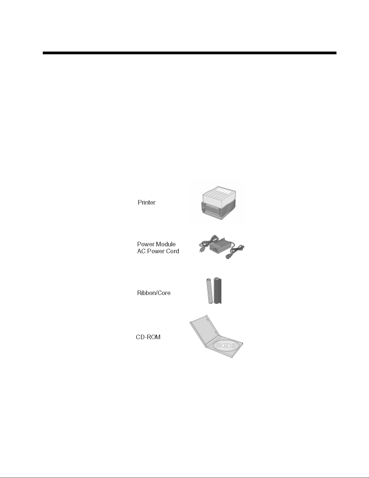
In addition to this manual, verify that you have the following materials when unpacking:
• The box should stay upright.
• Lift the printer out of the box carefully.
• Remove the plastic covering from the printer.
• Remove the accessory items from their protective containers.
• If the printer has been stored in a cold environment, allow it to reach room temperature
before applying power.
• Set the printer on a solid flat surface. Inspect the shipping container and printer for any
signs of damage that may have occured during shipping.
10
Page 20
SETTING UP THE PRINTER
Consider the following when setting up the printer
• Locate a solid flat surface with adequate room to set the printer. Make sure the Power
Module can be located so that the power connecting cable can be attached to the printer
and the AC Power Cable can be connected to an AC power outlet.
• The location should be near the host or computer terminal. The maximum distance is:
-10 feet for the Parallel interface. To fully utilize the capabilities of the
printer,a cable meeting IEEE 1284 specifications must be used.
-18 feet for the optional Serial RS232 Interface.
-10 feet for the optional USB interface without hub.
-the optional 10baseT Ethernet Interface depends on the LAN cabling.
• For imformation on interfacing the printer to a host system, see Section 5. Interface
Specifications.
Follow these steps to set up your printer:
1. Make sure the power switch on the
Operator Panel is in the OFF (0) position
and place the Power Module in a safe
and secure location, taking into
consideration the location of the AC
outlet and the host in relation to the
printer.
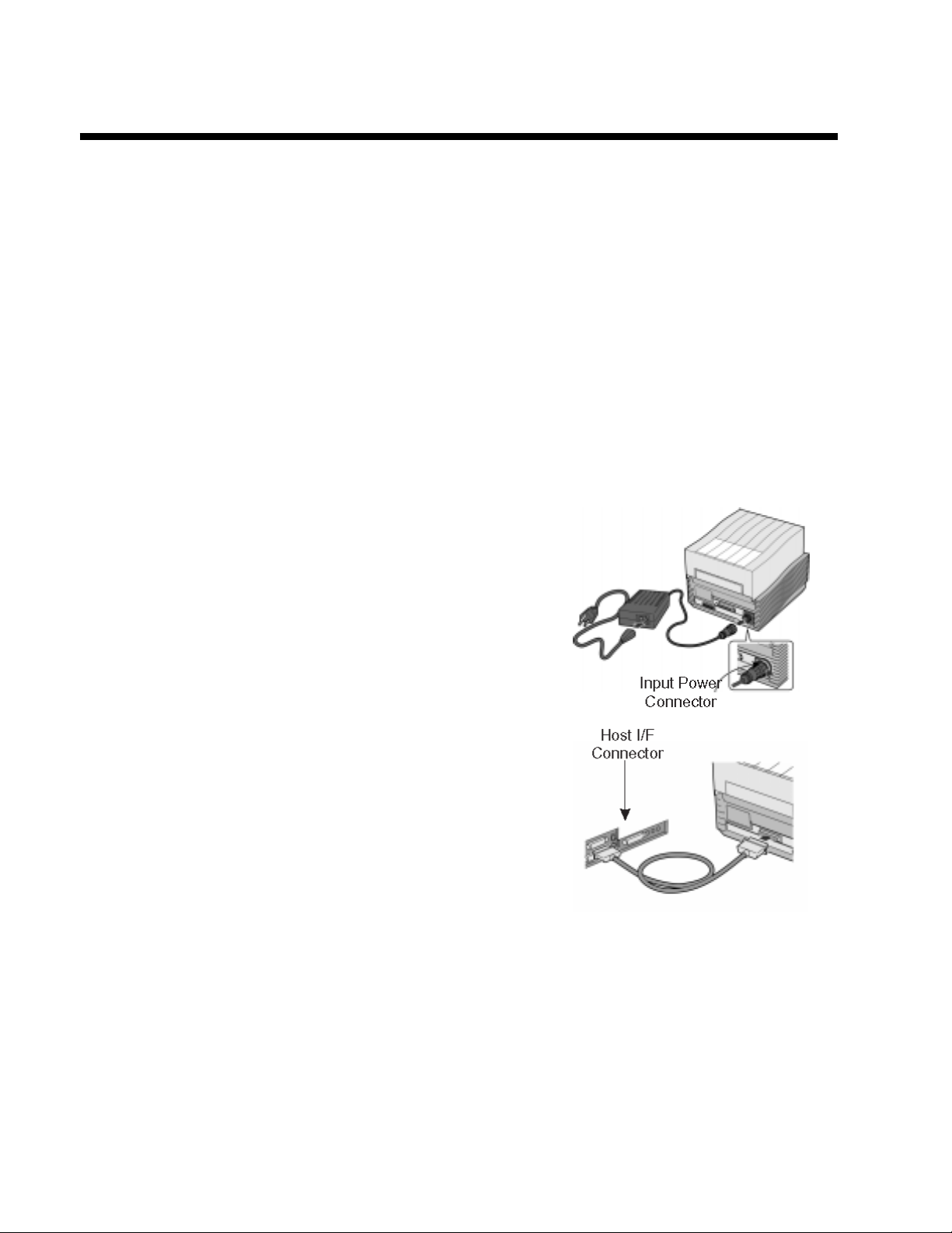
2. Connect the Input Power connector to the
printer. This connector is keyed and must
be turned approximately 3/4 turn
clockwise to secure it to the printer.
3. Connect the AC Power Cable to the proper
AC Outlet supply.
4. Connect the interface cable to the host system.
A parallel IEEE1284 interface cable must be
used to realize the high data transfer rate of
the printer’s parallel port. If an optional
interface is installed, the appropriate cable
should be used.
5. Load the ribbon and media following the
instructions in this section.
6. Configure the printer for label width and
operating mode using the instructions in this
section.
11
Page 21

7. Apply power to the printer by placing the AC Power switch in the ON (1) position.
8. Print a test label to verify the printer is set up and operating correctly.
12
Page 22
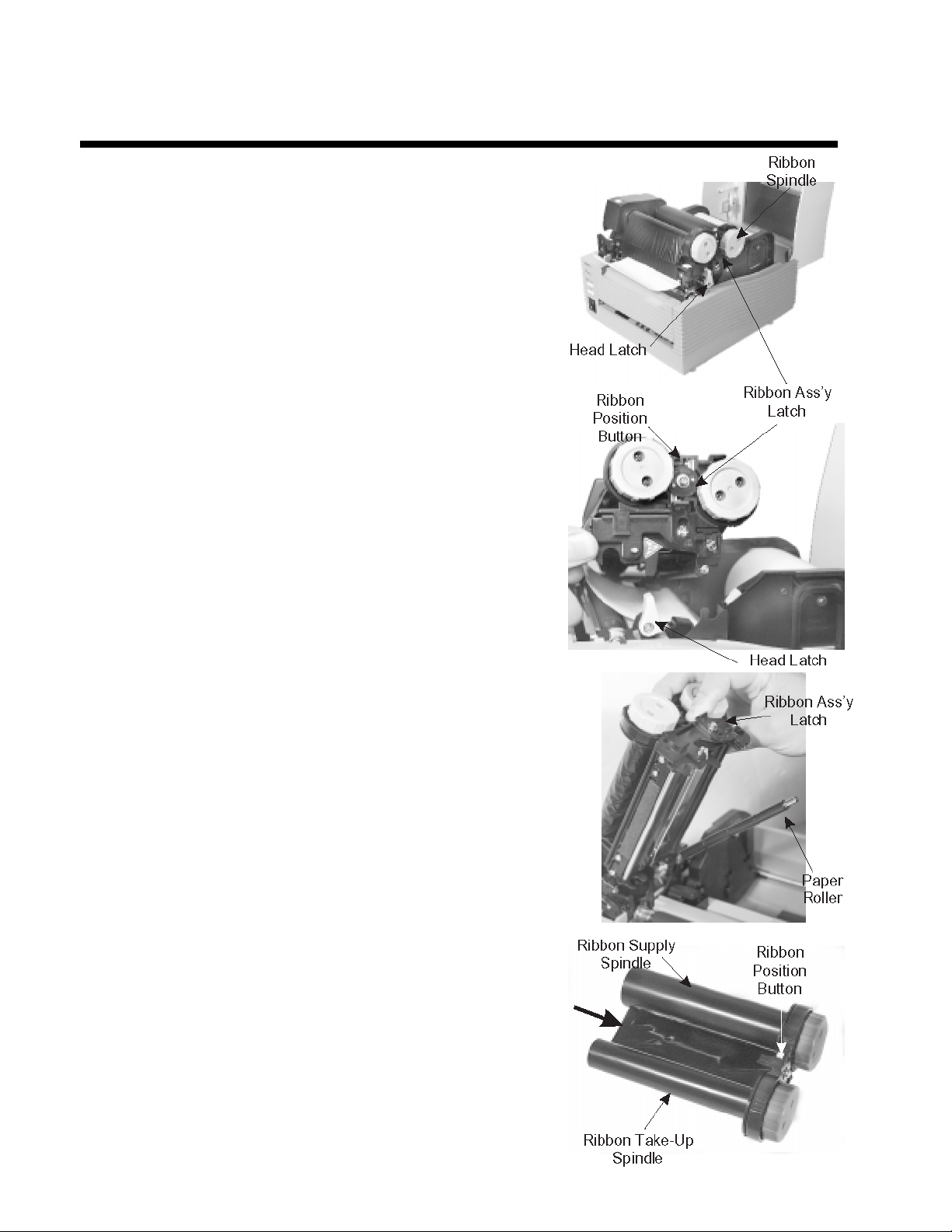
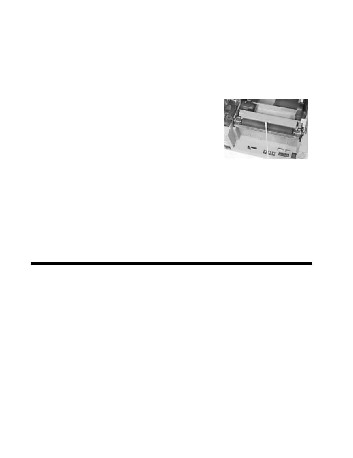
LOADING RIBBON (OKIPOS T4XXTT only)
The OKIPOS T400/T410 ribbons come Spindle
shrink-wrapped with a 12" (305 mm)leader
pre-attached to a takeup core. There are three widths
of ribbon available for the OKIPOS T400/T410
printers; 4.3" (110 mm), 3" (76 mm) and 1.75" (45
mm).
1. Remove power from the printer.
2. Open the Top Cover by pressing
the release points located on each side of the
printer. This releases the cover latch and
allows it to swing upward on the rear
mounted hinge points.
3. Release the Print Head Assembly by
pressing the Head Latch to the rear. This
allows the assembly to rotate upward to the
left allowing easy access for ribbon routing.
Rotate the assembly until it is vertical.
4. Press down on the Ribbon Assembly Latch.
This allows the Paper Roller to swing
downward for ribbon routing.
5. Press down on the Ribbon Positioning
button while simultaneously pulling upward
on the Ribbon Spindle Unit. The Ribbon
Spindle Unit should slide off.
6. Remove the shrink wrap from the ribbon and
unwind approximately 6" of the leader.
Press the Ribbon Supply core all the way
onto the rear spindle of Ribbon Spindle
Unit. Press the attached take-up core on the
front spindle. Make sure each of the cores is
fully seated on the spindles and there is
enough ribbon leader to go down around the
print head.
Note: OKIPOS T400/T410 ribbons are wound
face (ink side) out. Make sure the dull (ink)
13
Page 23
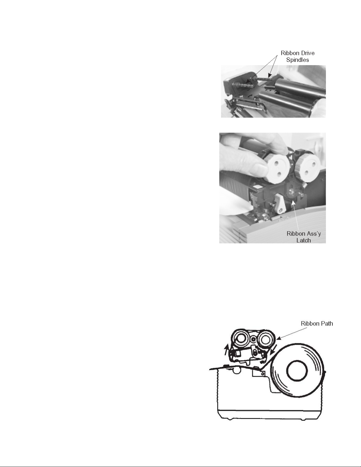
side of the ribbon will be in contact with
Ribbon Drive the paper and the supply core is
on the
Spindles rear spindle.
7. Slide the Ribbon Spindle Unit over the
Ribbon Drive Spindles until the Head
Positioning Latch snaps into position.
The first position corresponds to a 4.3"
ribbon width. If you are using a narrower
ribbon, press the Head Position Latch
while sliding the Ribbon Spindle Unit to
the correct position. There are three latch
positions, one for a 4.3" wide ribbon, one
for a 3" wide ribbon and one for a 1.75"
wide ribbon.
8. The ribbon should be centre justified (i.e.,
the centre of the ribbon roll should be
aligned with the centre of the print head).
If it is not, reposition the Ribbon
Spindle Unit on the Drive Spindles until
the Ribbon Position Latch is in the
correct position.
9. Route the ribbon leader under the print
head and between the Ribbon Assembly
and the Paper Roller. Rotate the take-up
spindle until the leader is completely
wound onto the take-up core.
10. Push the Ribbon Assembly Latch to the
up or locked position. Rotate the Paper
Roller upward and latch it by pushing
the Ribbon Assembly Latch into the
upward position.
11. Latch the Print Head Assembly in the
closed position by pushing downward on
the “PUSH” tabs on both sides of the
assembly until it latches in position.
14
Page 24
LOADING MEDIA
The OKIPOS T400/T410 printers can use die-cut labels, tag stock or continuous media. The
media supply can be either roll or fanfold.
Roll Media
Roll media should be between 0.90" (23 mm) and 4.5" (115 mm) in width and wound face-out on
a core with a minimum ID of 1.6" (40 mm).
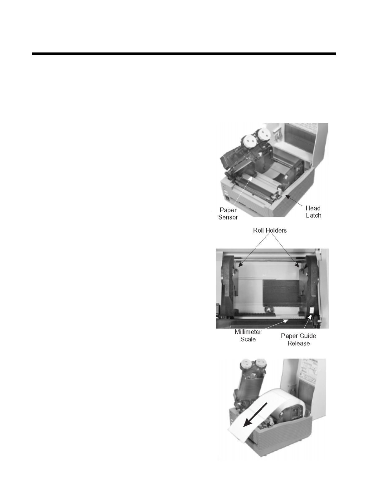
1. Remove power from the printer by
placing the Power Switch in the
OFF (0) position.
2. Open the Top Cover by pressing
on cover release points located on
each side of the printer. This
releases the cover latch and allows
it to swing upward on the rear
mounted hinge points.
3. Release the Print Head Assembly
by pressing the Head Latch to the
rear. This allows the assembly to
rotate upward to the left allowing
easy access for media routing.
Rotate the assembly until it is
vertical.
4. With the Print Head Assembly in
the up position, press the Paper
Guide Release while adjusting
the Paper Guides until they
allow a media roll to fit between
them. A millimeter scale is molded
into the case to provide a guide
when making the adjustment. The
Paper Guides are centre justified
and interact with each other so
that each moves an equal distance.
5. Make sure the Roll Holders are in
the released position. If they are
not, lift up on each one and they
will snap to the open position.
6. Unwind approximately 12" of label
material from the roll. The labels
should be wound face-out (printing
side to the outside of the roll).
Drop the roll in between the
Paper Guides so that the labels
15
Page 25
come off the top of the roll. The
Paper Guides will automatically
position the Roll Holders to
suspend the roll.
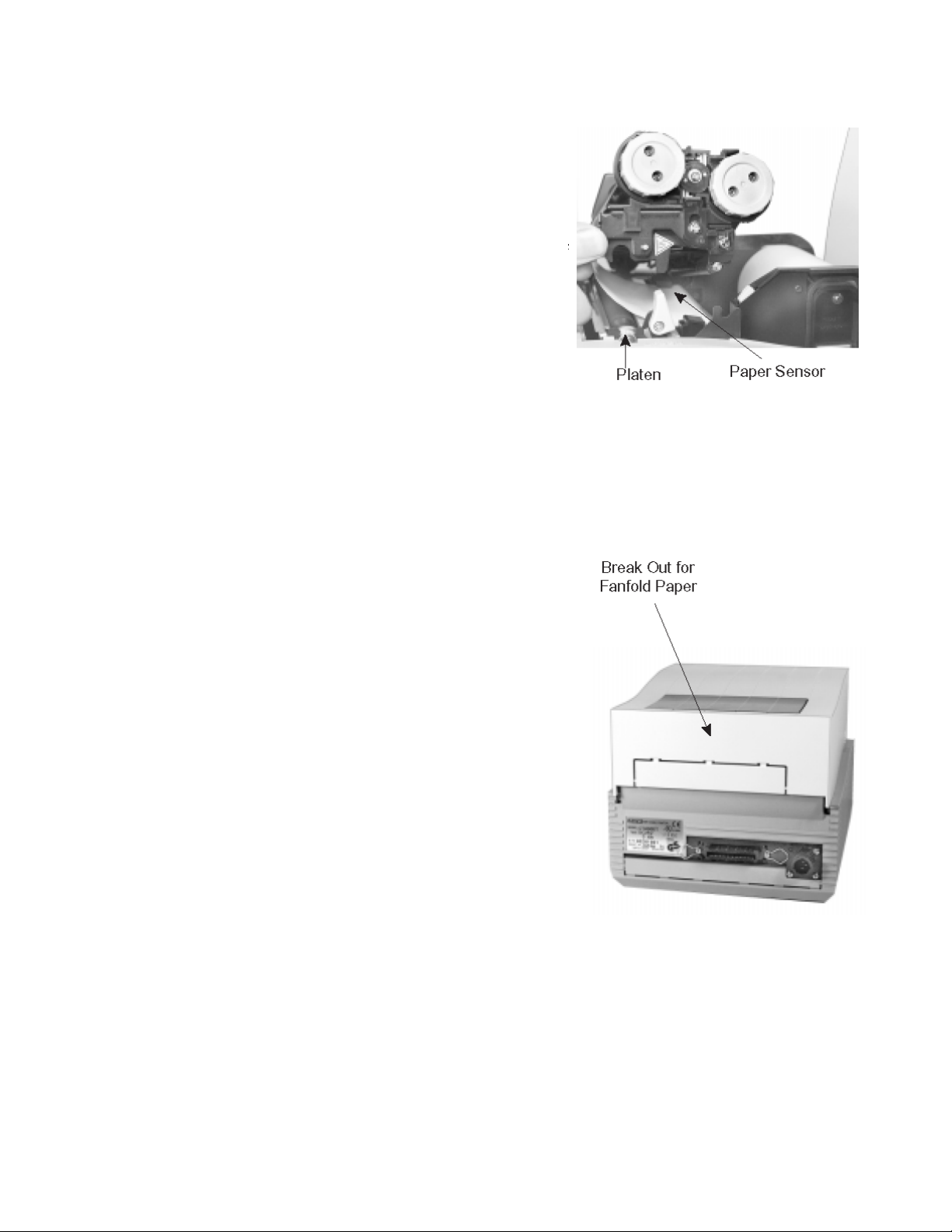
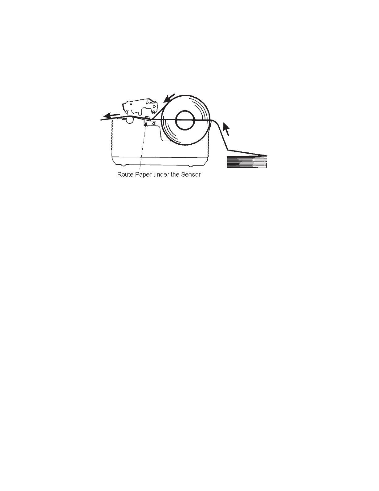
7. Route the label material through the
Paper Sensor Assembly and
over the Platen. Note that the
Sensor is part of the left Label
Roll Guide so that the Paper
Sensor is always positioned in the
same location relative to the left
8. Close and latch the Print Head Assembly.
9. Press the LINE key so that the printer is in the OFF LINE mode and then press the
FEED key. The label should advance to the next index (label gap or eye-mark) position.
Fanfold Media
1. Place the fanfold media behind the
printer with the printing surface
up.
2. Open the Top Cover by pressing on cover
release points located on each side of the
printer. This releases the cover latch and
allows it to swing upward on the rear
mounted hinge points.
3. Carefully break out the Fanfold Access
Panel from the back of the Top Cover.
4. Release the Print Head Assembly by
pressing the Head Latch to the rear. This
allows the assembly to rotate upward to the
left allowing easy access for ribbon routing.
Rotate the assembly until it is vertical.
5. With the Print Head Assembly in the up
position, press the Paper Guide Release while
adjusting the Paper Guides until they allow a
media to fit between them. A millimeter scale
is molded into the case to provide a guide
when making the adjustment. The Paper
Guides are centre justified and interact with
each other so that each moves an equal
distance.
6. Route the label material through the Sensor
Assembly and over the Platen.
16
Page 26
7. Close and latch Print Head Assembly.
8. After loading the ribbon and media, it is recommended that you run a Test Print to
make sure the labels and ribbon (for OKIPOS T4XXTT only) are correctly loaded. See
Section 2 for instructions on how to run test prints.
17
Page 27
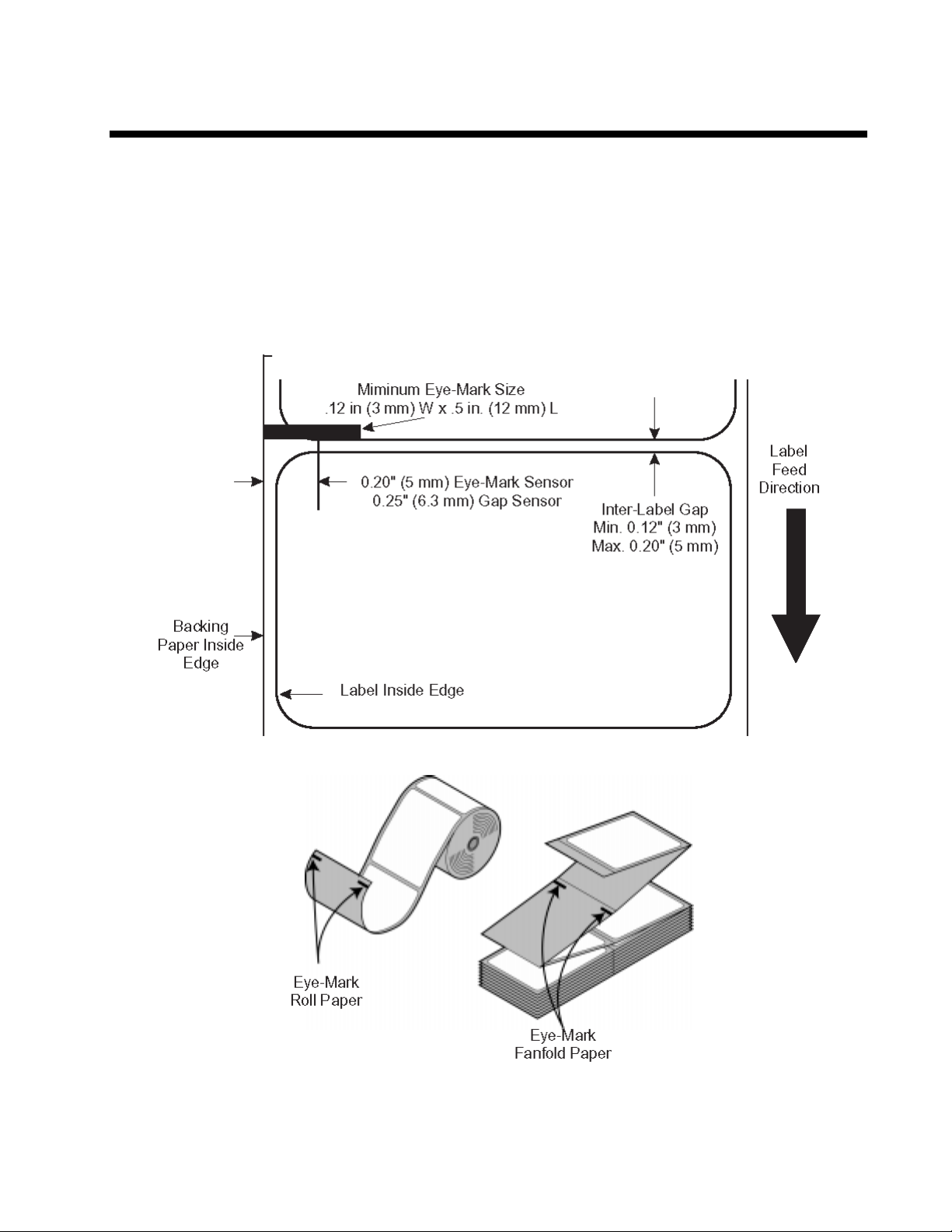
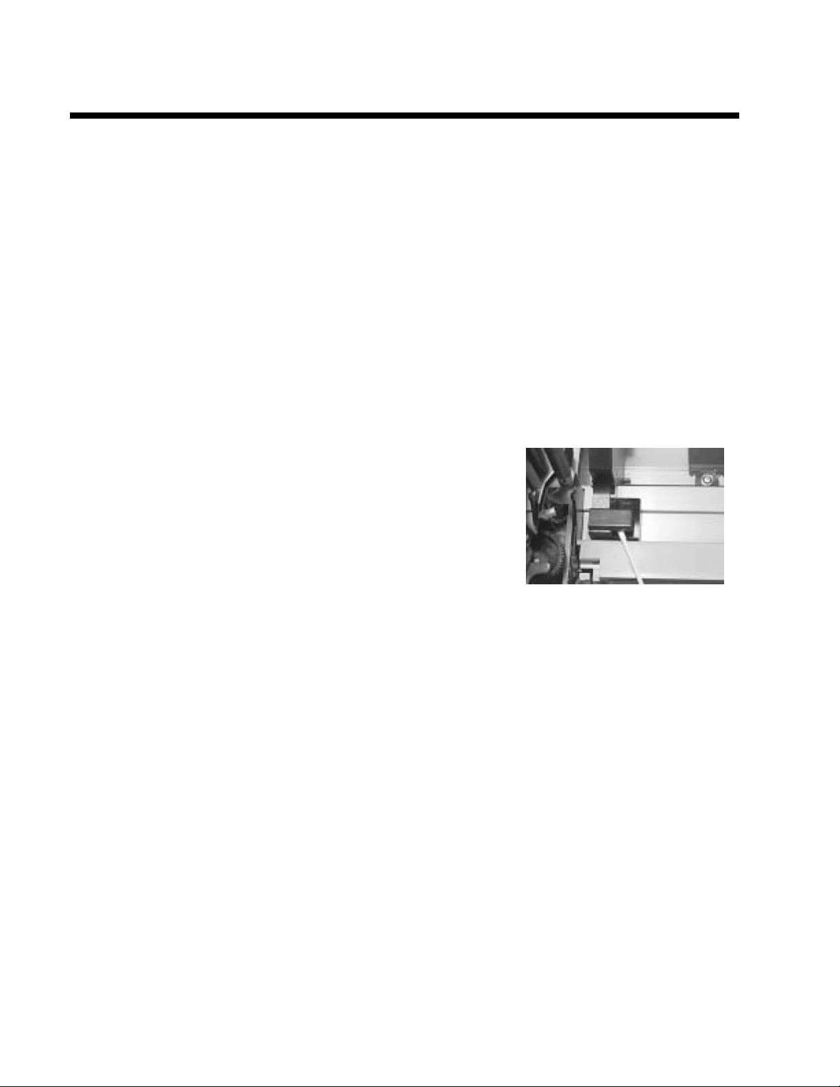
LABEL SENSING
The OKIPOS T400/T410 printers can use either label Gap (see-thru) or Eye-Mark (reflective)
sensing. The Sensor Assembly is located on the left edge of the media and is automatically
positioned by the Paper Guides.
The printer is shipped from the factory with the default sensing method set for label gap. The
setting can be overridden by using the <ESC>IG command (Section 4) however it will be reset to
the default when power is cycled. The default setting can be changed using the <ESC>PG
command (Section 4) or the Printer Configuration Utility program on the CDROM.
18
OKIPOS T400/T410 Printer Label Sensor Positioning
Page 28
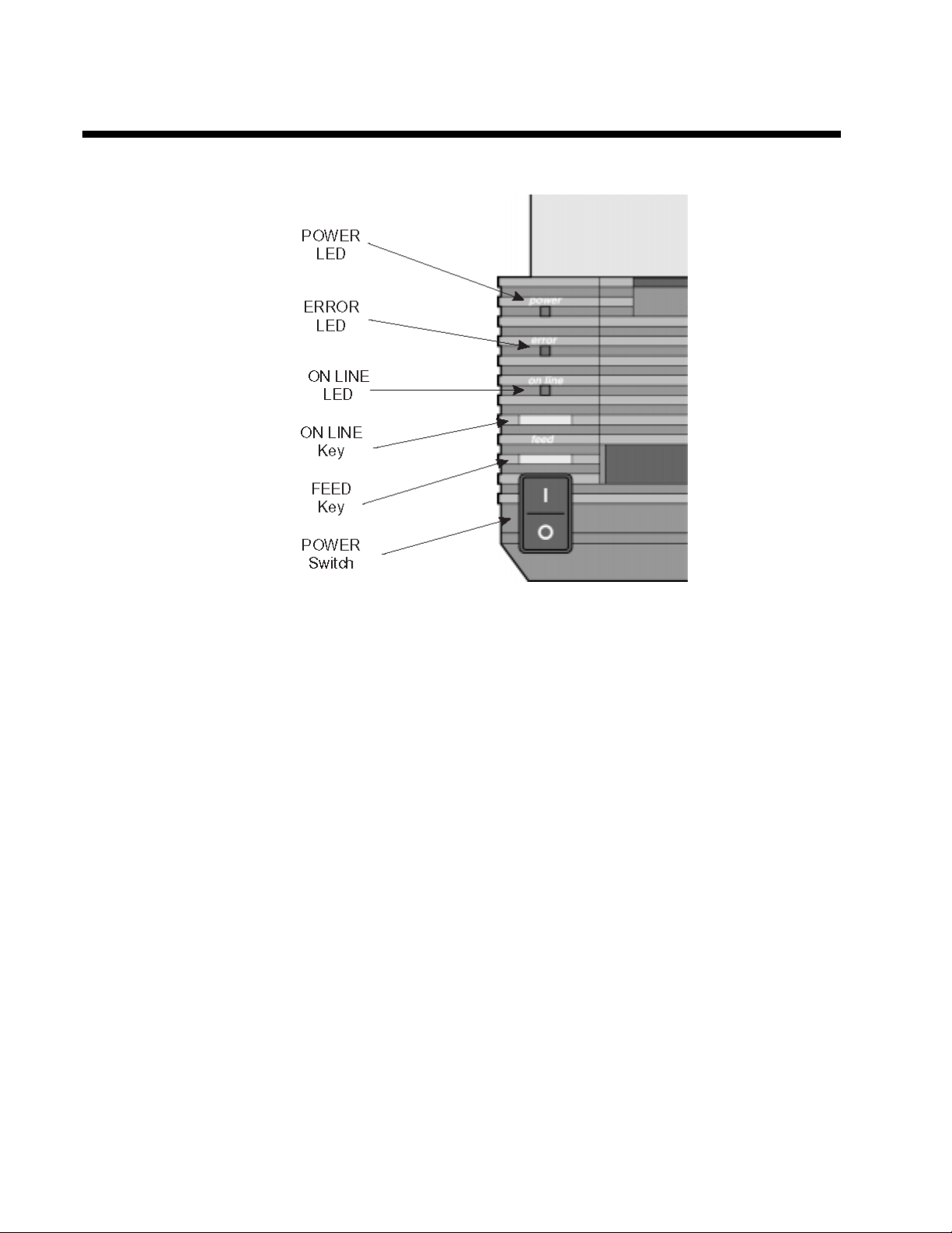
OPERATOR PANEL
The Operator Panel consists of three LED indicators and three switches.
POWER Green LED, illuminated when power is applied.
ERROR Red LED, illuminated when there is a system fault such as an open print
head.
ON LINE Green LED, illuminated when the printer is ON LINE and ready to receive
data. The printer is placed ON LINE and OFF LINE by toggling the ON
LINE key.
ON LINE KEY If the ONLINE LED is illuminated, pressing this switch will place the
printer in the OFFLINE mode. Pressing the switch again will place the
printer back in the ONLINE mode. If this switch is pressed while the
printer is printing, the printing process is suspended. To resume printing,
press this switch again. When the printer is ON LINE, it is ready to
receive data from the host. When it is OFF LINE, the printer will not
receive data from the host or print.
FEED KEY Feeds one label when pressed in the OFFLINE mode. If this switch is held
in the depressed position while power is applied, a printer status label will
be printed.
POWER A two position switch that applies power to the printer. When the “0"
position is pressed, power is removed from the printer. When the ”1"
position is pressed, power is applied to the printer.
19
Page 29
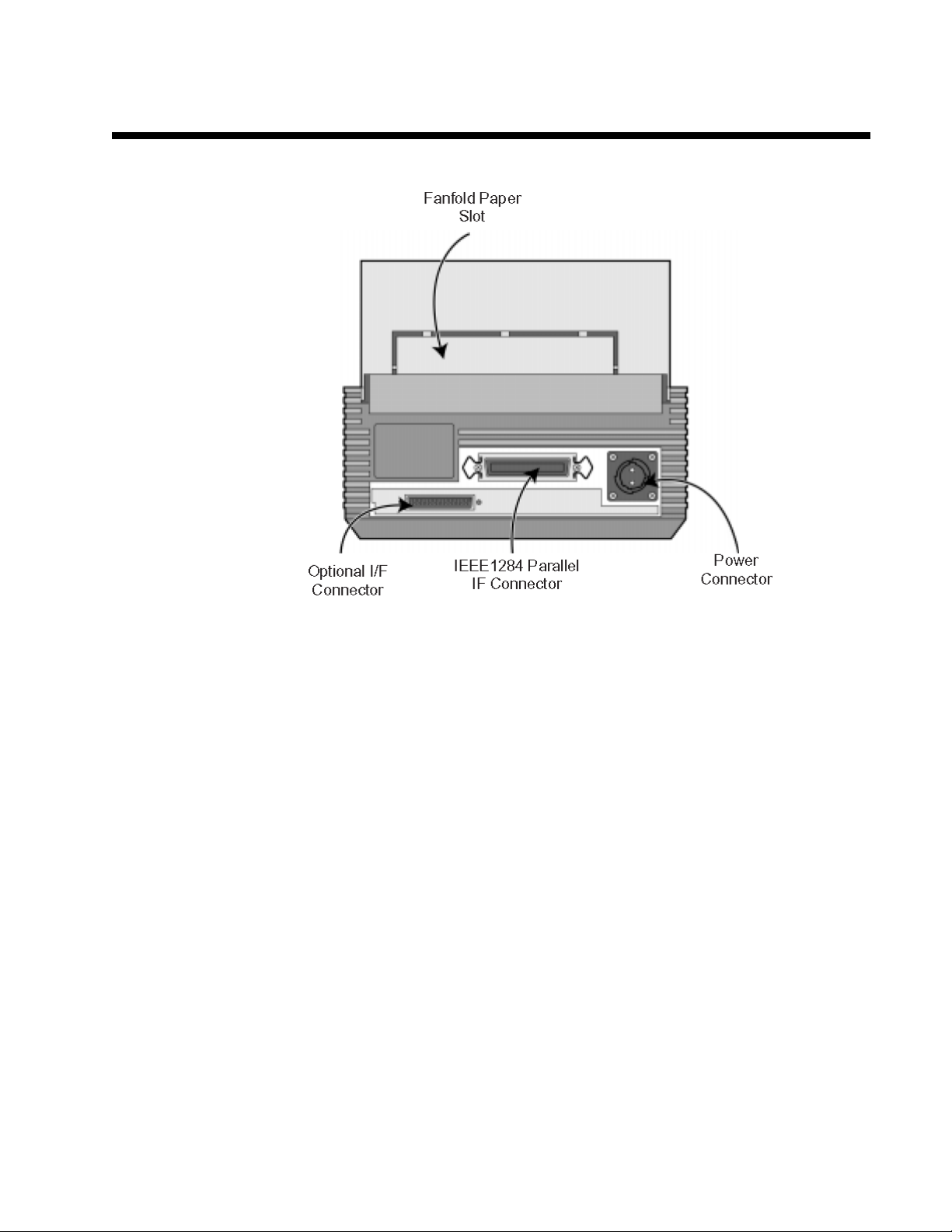
REAR CONNECTOR PANEL
All of the printer cable connectors are located on the Rear Connector Panel.
Power DC Power input to the printer. From Power Module.
Parallel Interface IEEE1284 Parallel Interface Connector..
Optional Interface Connector for any installed optional interface.
(if Installed)
Fanfold Paper Slot Slot for fanfold paper. Panel must be removed to route fanfold paper into
the printer.
20
Page 30
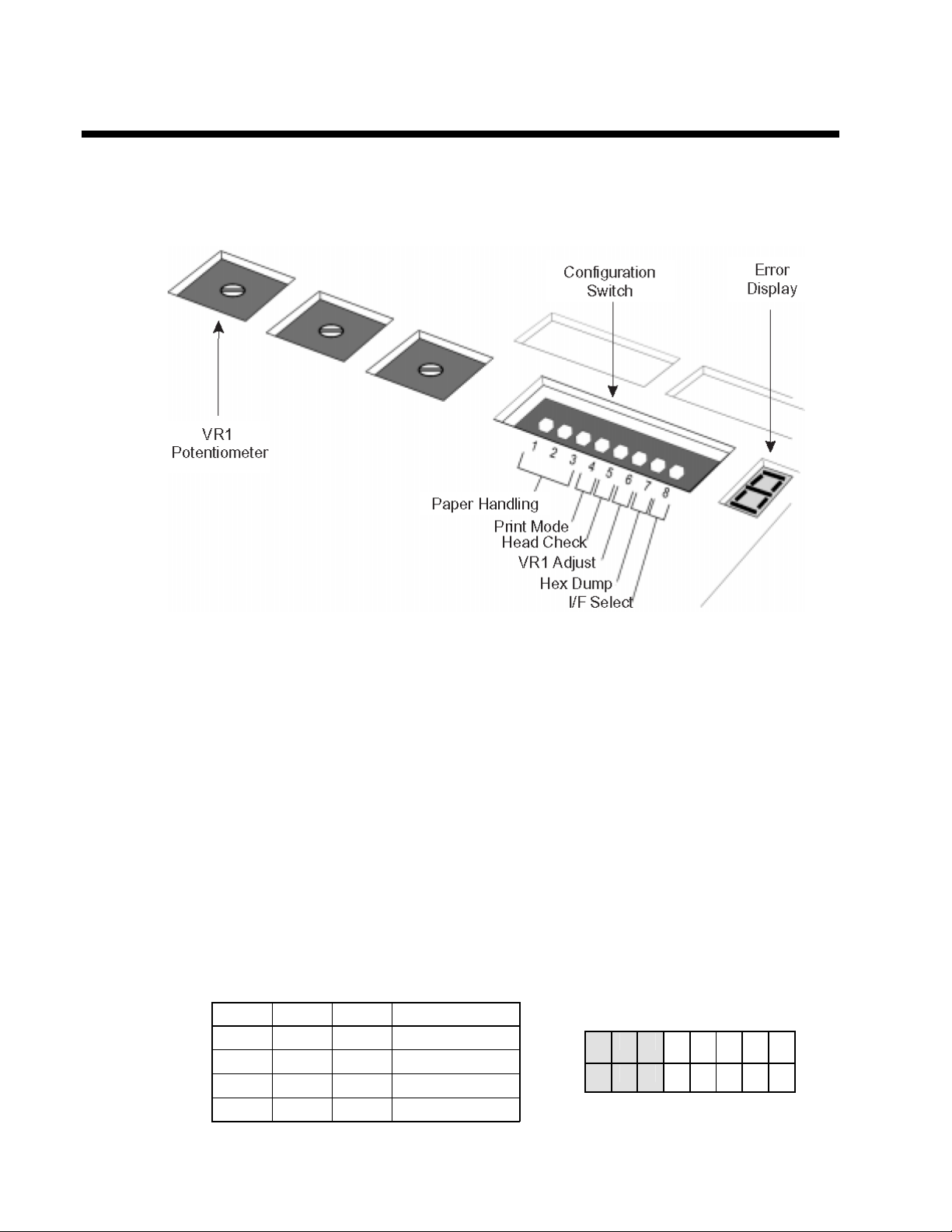
CONFIGURATION PANEL
The Configuration Panel can be accessed by opening the Top Cover. It consists of an eight
position DIP switch, three adjustment potentiometers and a seven segment LED Error display.
Receptacles for connecting the Dispenser and Cutter options are also located on this panel.
CONFIGURATION SWITCH
An eight position DIP switch is utilized for setting the operating conditions of the printer.
Paper Handling (DSW1-3). Selects the method used for controlling the paper handling.
Continuous - Does not use the sensor for paper indexing. The paper movement will
stop after all the label data has been printed.
Tear Off - Paper is fed out to the cut/tear off position after printing is complete. Before
the next label is printed, the paper is pulled back in to the first print line position.
Cutter Mode - Enables the Cutter option if installed.
Dispenser Mode - Enables the Label Taken sensor if the Dispenser option is installed.
DSW1 DSW2 DSW3 SETTING
Off Off Off Continuous
On Off Off Tear Off
Off On Off Cutter Mode
On On Off Dispenser
ON
OFF
1 2 3 4 5 6 7 8
Configuration Switch
21
Page 31

Font/Graphic Download (DS1-3). Enables the downloading of fonts and/or
graphics to printer memory.
DSW1 DSW2 DSW3 SETTING
Off On On Enable
ON
OFF
1 2 3 4 5 6 7 8
Configuration Switch
Print Method (DSW4). Selects Direct Thermal or Thermal Transfer print mode for a T4XXTT
printer.
Configuration Switch
DSW4 SETTING
Off Direct
On Transfer
ON
OFF
1 2 3 4 5 6 7 8
Head Check (DSW5). When selected, the printer will check for head elements that are electrically
malfunctioning.
Configuration Switch
DSW5 SETTING
Off Disabled
On Enabled
ON
OFF
1 2 3 4 5 6 7 8
VR1 Potentiometer Function (DSW6). Selects the function adjusted by VR1. When placed in the
Off position, VR1 will adjust the pitch offset value over a range of +/3.75 mm. When placed in the
On position, VR1 will adjust the print darkness range.
Configuration Switch
DSW6 SETTING
Off Pitch
On Darkness
Hex Dump (DSW7). When ON, the printer will print out the hex value for each character
received. When OFF, the printer will accept and process the data stream in a normal fashion.
ON
OFF
1 2 3 4 5 6 7 8
22
DSW7 SETTING
Off Normal
On Hex
Configuration Switch
ON
OFF
1 2 3 4 5 6 7 8
Page 32

Interface Select (DSW8). When OFF, the printer will activate the Parallel input port for receiving
data. When ON, the printer will activate the optional interface (if any) that is installed.
Configuration Switch
Configuration Switch
DSW8 SETTING
Off Parallel I/F
On Optional I/F
ON
OFF
1 2 3 4 5 6 7 8
ERROR DISPLAY
The ERROR dispay is a seven segment LED array that provides information on error conditions
detected by the printer. The conditions are:
LED ERROR
0 Flash Memory error.
1 Not Assigned
2 Motherboard error
3 EEPROM error
4 Electrical Head error
5 Head not latched in the down position
6 Out of Paper
7 Sensor type or level error
8 Cutter error
8. Program error
9 Ribbon End (TT mode only)
A Receive buffer overflow
b Parity error (Serial I/F only)
c Framing error (Serial I/F only)
d Overrun error (Serial I/F only)
E Time Out error
F Download Font/Graphic error
For more information the cause and troubleshooting of printer errors, see Section 6.
Troubleshooting.
23
Page 33

OFFSET
There are three offset setting stored in the printer; one for Dispense mode, one for the Cut mode and one for
the Tear-Off mode. These three offsets can be set independently for each job using the <ESC>PO Pitch Offset
command and will remain in the printer until a new command is received changing the setting or until power is
turned off. The <ESC>PG Printer Setting command can be used to change the default settings of the printer.
The default setting will always be active after power to the printer is cycled. The default settings can be
determined by printing a User Test Label or displayed by the Printer Configuration Utility Program on the
CD-ROM. Please note that the Printer Configuration Utility Program requires a bi-directional communications
port on a host that is running Windows 9X.
The following should be used as starting points for establishing the three Offset values:
MODE MILLIMETERS INCHES
CUTTER 17.9 0.70 143/215
DISPENSE 15.2 0.60 122/182
TEAR-OFF 29.2 1.15 234/350
POTENTIOMETER ADJUSTMENTS
PITCH OFFSET
After the Label Pitch Offset has been set using the <ESC>PO Pitch Offset command,it is
sometimes desirable to make minor adjustments. This can be done using the VR1 potentiomenter
on the Configuration Panel. This potentiometer is set at the factory so that it has a range of
+/-3.75 mm. The midpoint setting should have no effect on the label pitch. Turning the
potentiometer all the way clockwise should move the print position 3.75 mm upwards towards the
leading edge of the label. Turning it all the way counterclockwise should move the print position
down 3.75mm away from the leading edge of the label.
1. Place DSW6 on the Configuration Switch in the OFF position.
2. Turn the Power Switch OFF.
3. While pressing the FEED key on the Operator Panel, turn the Power Switch ON.
4. When you hear one beep from the printer, release the FEED key .
5. Press the LINE key to begin printing large Test Labels (press the FEED key if you are
using labels smaller than 4.1" (104 mm) in width).
DOTS
203/305 dpi
24
Page 34

5. Adjust potentiometer VR1 until the first print position is at the desired location on the
label. If the potentiometer does not have enough range, you will have to change the
Label Pitch setting using the <ESC>PO command.
Note:Theprinter will returntothedefaultsettings specified by the<ESC>PG command
whenpower is cycled.
6. Press the FEED key to stop the printing.
Note:Adjusting theLabel Pitchwith VR1willaffectthestop position ofthelabeland
thecut/dispense/tear-offpositions.
25
Page 35

Print Darkness
Print Darkness is set using the <ESC>#E Print Darkness command. A fine adjustment for PRINT
DARKNESS can be made using potentiometer VR1 on the Front Operator Panel. It provides a
continuous range of adjustment, allowing you to make precise changes. Turning VR1 clockwise
will make the print darker and counterclockwise will make it lighter.
1 Place DSW6 on the Configuration Switch in the ON position.
2. Turn the Power Switch OFF.
3. While pressing the FEED key on the Operator Panel, turn the Power Switch ON.
4. When you hear one beep from the printer, release the FEED key.
5. Press the LINE key to begin printing large Test Labels (press the FEED key if you are
using labels smaller than 4.1" (104 mm) in width).
6. Adjust potentiometer VR1 until the desired print darkness is obtained.
7. Press the FEED key to stop the printing.
Adjustment of the Print Darkness using VR1 will affect the darkness in all the <ESC>#E
command code ranges, i.e., if the print darkness is adjusted with VR1 for lighter print, the
darkness will be lighter in all the Print Darkness ranges selected by the command code.
26
Page 36

HEX DUMP DIAGNOSTIC LABEL
The contents of the printer buffer can be examined using the Hex Dump mode. This prints out
each line of the received data in the left hand column, the data in hex format in the middle column
followed by the same data in ASCII format in the right-hand column.
1. Turn the printer OFF.
2. Place DSW7 on the configuration Switch in the ON position.
3. Turn the printer ON.
4. Transmit data to the printer.
5. The data received is printed on the label.
6. Place DSW7 in the OFF position.
7. Turn the printer OFF and then back ON to place it back in the normal print mode.
27
Page 37

PRINT TEST LABELS
USER TEST PRINT
The User Test Label prints the current default setting of the printer. These settings can be changed
by sending new default settings with the <ESC>PG Printer Setting command.
1. Press the FEED key while simultaneously turning the POWER switch ON.
2. When the printer beeps, release the FEED key.
3. To print a large (4" wide) test label, press the ON-LINE key. To print a small (2" wide)
test label, press the FEED key.
4. The printer will continuously print the USER TEST LABEL until the FEED key is
pressed. If the FEED key is pressed a second time, printing will resume.
5. To remove the printer from the Test Label mode, power the printer OFF.
28
Page 38

FACTORY/SERVICE TEST PRINT
The Factory/Service Test Label prints the internal operating parameters of the printer.
1. Open the print head by pushing the Head Latch Lever to the rear.
2. Press the LINE and FEED keys while simultaneously turning the POWER switch to
the ON position.
3. When the printer beeps, release the LINE and FEED keys. The printer will then beep3
times indicating it is in the Factory/Service Print Test mode.
4. Latch the Print Head in the down position.
5. Press the LINE key to print a large (4" wide") Factory/Service Test Label. Press the
FEED key to print a small (2" wide) Factory/Service Test Label.
6. The printer will begin printing a series of test labels, the first containing the operational
parameters of the printer followed by one containing the internal printer settings. these
two label formats will alternate until the FEED key is pressed, suspending the print
operation. If the FEED key is pressed again, the printing will resume.
7. To remove the printer from the Factory/Service Print Test mode, remove power by
placing the POWER switch in the OFF position.
29
Page 39

This page left intentionally blank.
30
Page 40

SECTION 3.
CLEANING AND MAINTENANCE
INTRODUCTION
This section provides information on user maintenance for the OKIPOS T400/T410 printers. This
section contains the following information.
• Adjusting the Print Quality
• Cleaning the Print Head, Platen and Rollers
• Replacing the Print Head
• Replacing the Fuse
PROCEDURES
ADJUSTING THE PRINT QUALITY
The T400 and T410 printers are equipped with two different methods of adjusting the quality of
the print; print darkness and speed. When adjusting the printer for optimum print quality, a bar
code verifier system should be used. The human eye is a poor judge of the relative widths of the
bars in a symbol, a characteristic that is extremely important for good bar code quality.
Darkness (Print)
This adjustment allows the user to control (within a specified range) the amount of power that is
used to activate the individual print head heat elements. It is important to find a proper print
darkness level based on your particular label and ribbon combination. The printed images
should not be too light nor should the ink from the ribbon “bleed.” The edges of each image
should be crisp and well defined.
The print darkness level can be set by downloading the setting using the <ESC>#E Print Darkness
software command (see Section 4, Programming Reference). There are five ranges 1 through 5,
with the lightest setting being 1 and the darkest setting being 5. The <ESC>#E Print Darkness
command also provides for darkness ranges matched to the type of media used. Setting “A” is
used for Direct thermal media and “B” for coated thermal transfer media.
Once the range has been selected, the PRINT Potentiometer on the front panel can be used to
make finer adjustments.
31
Page 41

Print
The fine adjustment for Print Darkness is the VR1 potentiometer on the operator panel. It
provides a continuous range of adjustment, allowing you to make precise changes. Use a small
cross-point screwdriver, turning clockwise for darker print and counterclockwise for lighter
print. See Section 2: Installation and Configuration for instructions on performing
potentiometer adjustments
NOTE: The PRINTpotentiometer adjustment wi
affect the darkness in a of the command
code speed ranges, i.e. if the PRINTpotentiometer is adjusted for lighter print, the darkness will be
lighter in all speed ranges selected by the command code.
Print Speed
The other method of controlling print quality is by controlling the speed at which the label is
printed. This adjustment is made only on an individual label basis using the <ESC>CSPrint Speed
command code. For more details on this command, see Section
4: Programming. Changing the print speed allows the user to control the amount of time allowed
for print element cooling before the media is stepped to the next print position. It is especially
critical when printing “ladder” bar codes (bar codes printed with the bars parallel to the print line).
When printing a “ladder” bar code, it is important to allow the head to cool sufficiently before
stepping to the next position. If it does not have sufficient time to cool, the bar will be “smeared”
on the trailing edge.
CLEANING THE PRINT HEAD, PLATEN AND ROLLERS
Supplies needed: OKI SA070 Cleaning Kit
CLEANING THE PRINT HEAD
1. Turn the printer off and remove the power
cable.
32
2. Open the Top Cover.
3. Open the Print Head Assembly by pushing
the Head Latch toward the rear of the printer.
The Print Head Assembly is spring-loaded
and will automatically open as soon as the
Head Latch is disengaged.
4. Rotate the Print Head Assembly upward to
give access to the Print Head.
5. Remove the ribbon.
6. Apply OKI Thermal Print Head Cleaner to
a cotton swab.
5. The Print Head faces downward along the
front edge of the assembly. Pass the end of
the dampened swab along the entire width of
the Print Head.
Page 42
5. Check for any black coloring or adhesive on the swab after cleaning.
6. Repeat if necessary until the swab is clean after it is passed over the head.
7. The head should be cleaned at least every time the ribbon is changed and more often in
harsh environments.
CLEANING THE PLATEN AND PAPER ROLLER
1. Turn the printer off and remove the power cord.
2. Open the Top Cover.
3. Open the Print Head Assembly by pushing the
Head Latch toward the rear of the printer. The
Print Head Assembly is spring-loaded and will
automatically open as soon as the Head Latch is
disengaged. Rotate the Print Head Assembly
upward to give access to the Platen and Ribbon
Roller. Remove any labels in the printer.
4. Apply OKI Thermal Print Head Cleaner to one of the cotton swabs.
5. The Platen is the rubber roller directly below the Print Head. It should be cleaned of any
ribbon or label residue. The Platen is easily cleaned by rotating the Platen with your
thumb while cleaning the residue with the cotton swab.
6. The Paper Roller is located at the rear of the Print Head Assembly. It should be cleaned
of any residue or foreign material.
7. Repeat if necessary. The platen and rollers should be cleaned whenever foreign matter
such as dust or adhesive is present.
REPLACING THE PRINT HEAD
The print head on the OKIPOS T400/T410 printers is a user-replaceable item. If it becomes
damaged for any reason, it can be easily removed and replaced. Contact your local Oki Data
representative for information on obtaining a new print head.
Supplies needed: No. 2 Phillips screwdriver (a magnetic tip is helpful)
1. Turn the printer off and remove the power cable.
2. Open the Top Cover.
3. Open the Print Head Assembly by pushing the Head Latch toward the rear of the
printer. The Print Head Assembly is spring-loaded and will automatically open as soon
as the Head Latch is disengaged.
4. Remove the ribbon from the Ribbon Spindle unit if the printer is a thermal transfer
version.
33
Page 43

5. View the Print Head Assembly from the
front of the printer. Locate the mounting
screw on the top of the assembly. It is
accessible through a hole in the top of the
assembly . Unscrew these Head Retaining
screw and set it aside.
6. The Print Head should now be loosened
from the top of the assembly by grasping
either side and carefully pulling it forward.
7. Disconnect the connecting cable from the
print head connectors and set the Print Head
aside.
8. Carefully attach the new Print Head to the
connectors, using caution to make sure the
connector keys are correctly positioned. The
connector is keyed so that it can only be
inserted easily in the correct orientation.
NOTE: Be careful not to scratch the printing
surface of the print head while installing it.
Scratching the surface will cause permanent and
irreparable damage and is not covered by the
warranty!
9. Locate the mounting screw in the top plate
assembly and align it with the tapped holes in
the new Print Head.
10. Re-secure the print head by tightening the
screw.
34
Page 44
CLEANING THE SENSORS
There are two sensors that are used to control the positioning of the label. One is a transmissive
see-thru sensor that detects the edge of the label by looking through the backing paper which is
translucent and detecting the presence of the opaque label. The other is a reflective sensor that
detects the light reflected from the bottom of the label liner. When a printed black Eye-Mark
passes through the beam, the light is no longer reflected back to the sensor detector, indicating to
the printer that it should use this position as the start of a new label. When dust, dirt or other
foreign matter interferes with the light path of either of these sensors, the results is erratic label
positioning. These sensors should be cleaned regularly, at least every two rolls of labels.
Supplies Needed: OKI SA070 Cleaning Kit
1. Turn the printer off and remove the power cable.
2. Open the Top Cover.
3. Open the Print Head Assembly by pushing
the Head Latch toward the rear of the printer.
The Print Head Assembly is spring-loaded
and will automatically open as soon as the
Head Latch is disengaged. The sensors are
built into the left hand Label Guide so that
they move whenever the Label Guides are
adjusted for different media widths.
4. Apply OKI Thermal Print Head Cleaner to
one of the cotton swabs.
5. Use the cotton swab to clean any foreign matter from the exposed surface of the sensors
by inserting the cotton tip in the paper slot and briskly cleaning it with a back and forth
motion.
35
Page 45

This page left intentionally blank.
36
Page 46

SECTION 4.
PROGRAMMING
INTRODUCTION
This section presents the commands that are used with the OKIPOS T400/T410 printers to
produce labels with logos, bar codes and alphanumeric data. All of the CT commands use the
same syntax. Some commands reference a physical point on the label using horizontal and
vertical dot reference numbers. The allowable range for these references is dependent upon the
particular printer to accommodate different print widths and resolutions. These differences are
noted in tables under the commands affected.
The following information is presented in this section:
• The OKI Programming Language
• Protocol Control Codes
• Using Basic
• The Print Area
• Command Codes
THE OKIPOS T400/T410 PROGRAMMING LANGUAGE
A programming language for a printer is a familiar concept to most programmers. It is a group of
commands that are designed to use the internal intelligence of the printer. The commands, which
are referred to as CT Command Codes, contain nonprintable ASCII characters (such as <STX>,
<ETX>, <ESC>) and printable characters. These commands must be assembled into an
organized block of code to be sent as one data stream to the printer, which in turn interprets the
command codes and generates the desired label output. The programmer is free to use any
programming language available to send the desired data to the OKIPOS T400/T410 printer.
The command codes used by the OKIPOS T400/T410 Printers are based upon “Escape” (1B
hexadecimal) sequences. Typically there are four types of command sequences:
<ESC>{Command}
These commands generally tell the printer to perform a specific action, like “clear the memory.”
<ESC>{Command} {Data}
Commands with this format tell the printer to perform a specific action which is dependent upon
the following data, like “print X labels”, where the value for X is contained in the data.
<ESC>{Command} {Parameter}
37
Page 47

These commands set the operational parameters of the printer, like “set the print speed to 3.”
<ESC> {Command} {Parameter} {Data}
Some commands can contain both Parameter and Data elements, such as “print a Code 39 symbol
containing the data”.
PROTOCOL CONTROL CODES
Protocol codes are the special control characters that prepare the printer to receive instructions.
For example, the <ESC> character tells the printer that a command code will follow and the
<ENQ> character asks for the printer status.
There are two pre-defined different sets of Protocol Control codes to choose from. Each set is
made up of six special characters. The Standard Protocol Control codes are nonprintable
characters, and the Non-Standard Protocol Control codes are printable characters. The
Non-Standard set may be useful on host computers using protocol converters or in an application
where nonprintable ASCII characters cannot be sent from the host. This manual uses the Standard
Protocol Control codes for all of the examples.
CHARACTER VALUE
USING BASIC
It may be useful to test your CT printer using a BASIC program on a PC. You may also write
your actual production programs in BASIC. Whatever the reason, if you will be working in
BASIC, some of the following hints may help you get started:
CONTROL HEX DESCRIPTION
SOH 01 Status Request
STX 02 Start of Data
ETX 03 End of Data
ESC 1B Command code to follow
NULL 00 Cutter command
~
ENQ 05 Get printer status, Bi-Com Mode
CAN 18 Cancel Print Job
DLE 10 Print Stop
DC1 11 Print Start
Off-Line 40 Hex Take printer Off-Line
7E (Responds to either)
38
1. Set the WIDTH of the output device to 255 characters to avoid automatically sending <CR> and
<LF> characters after every line. The command string should be continuous and uninterrupted by
<CR> and/or <LF> commands. The examples given in this manual are printed on separate lines
because they will not fit on one line and do not contain any <CR> and/or <LF> characters. If
these characters are needed, they are explicitly noted by the inclusion of <CR> and <LF>
notations.
Page 48

2. If you are using the printer’s RS232 interface, it is necessary to set the COM port on the PC such
that the CTS and DSR signals will be ignored. Send your OPEN “COM” statement in the
following way:
OPEN “COM1:9600,E,8,1,CS,DS” AS #1
This sets the RS232 communication parameters of the host PC’s COM1 port for 9600 baud, Even
parity, 8 Data bits, 1 Stop bit and directing the port to ignore the CTS and DSR control signals.
3. You may want to minimize keystrokes and program size by assigning the <ESC> character to a
string variable since this character is used quite often.
The following two examples in BASIC show a typical example using these hints. Both of these
examples use the Standard Protocol codes.
Printing with the Parallel Port
5 REM T410 Parallel Example Identifies the program as a T410 parallel
port print label. The “REM” prevents this
data from being sent to the printer and
displays it only on the screen.
10 E$=CHR$(27); Sets the “E$” string as an <ESC>
character
20 WIDTH “LPT1:”,255; Sets the width of the output to 255
characters
30 LPRINT E$;"A"; Sends an “<ESC>A” command code to
the LPT1 parallel port
40 LPRINT E$;"H400";E$;"V100";E$;"XL1OKI"; Sends the data “OKI” to be placed 400
dots horizontally and 100 dots
vertically on the label and printed in
the “XL” font.
50 LPRINT E$;"Q1"; Instructs the printer
to print one label.
60 LPRINT E$; “Z”; Tells the printer that the last command
has been sent. The printer can now
create and print the job.
Printing with the RS232 Port
5 REM T410 RS232 Example Identifies the program as a T410 RS232
port print label. The “REM” prevents this
data from being sent to the printer and
displays it only on the screen.
10 E$=CHR$(27); Sets the “E$” string as an <ESC>
character.
20 OPEN “COM1:9600,N,8,1,CS,DS” AS #1; Opens the COM1 port for output and sets
the parameters as 9600 baud, No parity, 8
Data bits, 1 Stop bit and instructs the port
to ignore the CTS and DSR control
signals.
39
Page 49

30 PRINT #1,CHR$ (2); Sends an <STX> (ASCII Code a
decimal “2”) to the printer instructing it
to prepare to receive a message.
50 PRINT #1,E$;"A"; Sends an “<ESC>A” command code to
Print Port #1 opened by statement 20
above.
60 PRINT #1, E$;"H400";E$;"V100";E$;"XL1OKI"; Sends the data “OKI” to be placed 400
dots horizontally and 100 dots vertically
on the label and printed in the “XL”
autosmoothed font.
50 PRINT #1, E$;"Q1"; Instructs the printer to print a quantity of
one label.
60 PRINT #1, E$; “Z”; Tells the printer that the last command
has been sent. The printer can now create
and print the job.
70 PRINT #1,CHR$ (3); Sends an <ETX> (ASCII Code decimal
“3”) to the printer telling it that this is the
end of the message.
THE PRINT AREA
The maximum print area for the various OKIPOS T400/T410 printers is listed in Table 4.1, Print
Area. Most of your label applications will not require labels that fill the entire print area. To make
label design simpler, the media on the OKIPOS T400/T410 printers is centre justified, i.e. the
label is always centred on the print head. An <ESC>A1 Media Size command is then used to
specify the length and width of the label. The OKIPOS T400/T410 printer uses this information
to automatically calculate an “offset” that will move the Horizontal Reference point to coincide
with the first printable dot position on the specified label. It is extremely important to use the
Media Size command. If you do not, you will have to manually calculate the offset and send it to
the printer using the <ESC>A3 Base Reference Point command.
The diagram below illustrates the maximum print area and a sample 2 inch wide by 3 inch long
label placed within this area. As can be seen, your label will be oriented in the middle of the print
head as viewed from the front of the printer. The normal
Resolution
Max Print Width
Table 4.1, Print Area
T400 T410
203 dpi
8 dpmm
832 dots
4.1 in.
104 mm
305 dpi
12 dpmm
1248 dots
4.1 in.
104 mm
40
Max Label Width
Print Length
4.5 in.
115 mm
3200 dots
15.7 in.
400 mm
4.5 in.
115 mm
4800 dots
15.7 in.
400 mm
Page 50

reference point is located at the H1, V1 position of the print area in the normal print orientation
(no rotation).
41
Page 51

ROTATED FIELDS
The OKIPOS T400/T410 printers can rotate each print field in 90° increments using the
<ESC>% Rotate command.
The following data stream will rotate the print field but will not change the base reference point
of the field:
<ESC>A<ESC>%1<ESC>V800<ESC>H200<ESC>L0202<ESC>XB1E<ESC>Q1<ESC>Z
COMMAND DEFAULT SETTINGS
There are some types of commands that must have a value specified before a label can be printed.
If the data stream does not contain these commands, a “default” value is assumed. The default
settings are determined by the values specified in the last <ESC>PG Printer Setting command
sent to the printer. These values are stored in EEPROM and will remain valid even if power to the
printer is cycled.
COMMAND CODES
This section contains all the OKIPOS T400/T410 printer Command Codes. The commands must
be sent to the printer in an organized fashion in order for the label(s) to print.
The purpose of this section is to:
1. Explain the different commands and provide examples of their usage.
2. To provide a detailed reference for programming the OKIPOS T400/T410 Printers.
Each command begins on a separate page with its own heading. A uniform layout is used to help
you find key information about each command. For each Command
42
Page 52

Code in this section, there will be a sample data input stream to the printer and the expected print
output. By studying the examples, you can learn how to use the particular command within a
whole block of printer code. Pay particular attention to the “Special Notes” with each command
to learn other important information.
The subject commands are highlighted in bold letters in the Reference Sheets. There are two parts
of most, but not all, commands. The first is the command character which immediately follows
the <ESC> code. It is always an upper case alpha or a special character (such as an “&” or a “%”).
It is never a lower case alpha character. If the command requires additional variable information,
it is represented by a group of lower case alpha characters immediately following the command
character. For example, if an aaaabb is listed following the basic command, the printer will look
for six characters immediately following the command. The first four would represent the value
of aaaa and the next two the value of bb.
The maximum number of characters defined in a parameter is represented by the number of
characters shown in the command structure. For example, a command followed by an aaaa can
have up to four characters. In general, commands with only one parameter following the
command can be entered without the leading zeroes. However, certain commands require the
exact number of matching characters. A command with two parameters listed following the
command code without a comma delimiter, such as aaaabbbb require the exact number of digits
to be entered. If the value of aaaa is “800” and the value of bbbb is “300”, then the parameters
must be entered as “08000300”. It is recommended that you make it a practice to always enter
leading zeros to prevent any mistakes.
NOTE: These examples assume the use of the Standard Protocol Command Codes, a parallel
interface and a 4 inch wide label in a OKIPOS T400 printer. The labels for all other printers will
be similar, but, because of different resolutions and print widths may be larger or scaled
differently.
An alphabetical listing of the command codes is contained in Appendix A: Command Code
Quick Reference.
43
Page 53

This page left intentionally blank.
44
Page 54

Bar Codes
Command Structure 1:3 narrow/wide bar ratio: <ESC>Babbcccd
2:5 narrow/wide ratio: <ESC>BDabbcccd
1:2 narrow/wide bar ratio: <ESC>Dabbcccd
a = Bar Code Symbol
0 Codabar
1 Code 39
2 Interleaved 2 of 5 (I 2/5)
3 UPC-A / EAN-13
4 EAN-8
5 Industrial 2 of 5
6 Matrix 2 of 5
7 reserved
8 reserved
9 reserved
A MSI
B reserved
C Code 93
D reserved
E UPC-E
F Bookland
G Code 128
I UCC 128
bb = Number of dots (01-12) for narrow bar and narrow space
ccc = Bar height in dots (001-600)
d = UCC 128 only. Not used for other bar code types
0 No human readable text
1 Human readable at top
2 Human readable at bottom
Example: <ESC>BD103200
Placement: Immediately preceding data to be encoded
Default: None
Command Function To print bar code images on a label. With this command, there are 13 standard bar
code symbologies available to be printed and 3 two dimensional symbols (see
Two Dimensional Bar Code Symbols at the end of this section). Each of the bar
codes is unique, and it is important to know the differences. See Appendix B for
specific information on using each individual bar code symbol.
45
Page 55

Input to Printer <ESC>A
<ESC>H050<ESC>V0025<ESC>B103100*CODE 39*
<ESC>H0230<ESC>V0130<ESC>XS*CODE 39*
<ESC>H050<ESC>V0175<ESC>BD20310045676567
<ESC>H0215<ESC>V0285<ESC>XM45676567
<ESC>H050<ESC>V0325<ESC>BD30215001234567890
<ESC>H050<ESC>V0525<ESC>BD50310012345
<ESC>H0250<ESC>V0635<ESC>XS12345
<ESC>H050<ESC>V0675<ESC>BD60310012345
<ESC>H0230<ESC>V0785<ESC>XS12345
<ESC>H050<ESC>V0825<ESC>BA03100123455
<ESC>H0170<ESC>V935<ESC>XS12345
<ESC>H050<ESC>V980<ESC>BC03100081234ABCD
<ESC>H0155<ESC>V1095<ESC>XS1234ABCD
<ESC>H050<ESC>V1130<ESC>B002100A12345B
<ESC>H090<ESC>V1240<ESC>XS12345
<ESC>H0530<ESC>V0025<ESC>BD303100123456789012
<ESC>H0590<ESC>V0525<ESC>BD4031001234567
<ESC>H0575<ESC>V175<ESC>DE03100123456
<ESC>H0550<ESC>V0225<ESC>OB0 <ESC>H0583<
ESC>V0280<ESC>OB123456
<ESC>H0325<ESC>V0325<ESC>D30315009827721123
<ESC>L0101<ESC>H0295<ESC>V0400<ESC>OB0
<ESC>H0340<ESC>V0478<ESC>OB98277 <ESC>H
0480<ESC>V0478<ESC>OB21123
<ESC>H630<ESC>V0365<ESC>BF0313021826
<ESC>H645<ESC>V0335<ESC>OB21826
<ESC>H0450<ESC>V0675<ESC>D30315000633895260
<ESC>L0101<ESC>H0415<ESC>V0750<ESC>OB0
<ESC>H0465<ESC>V0828<ESC>OB06338 <ESC>H 0605<ESC>V0828<ESC>OB95260
<ESC>H0755<ESC>V0705<ESC>BF0314024
<ESC>H0770<ESC>V0675<ESC>OB24
<ESC>H0450<ESC>V0980<ESC>BG03100>GAB>B789>C123456
<ESC>H0560<ESC>V1085<ESC>XS AB789123456
<ESC>Q1<ESC>Z
Note: Carriage Returns and Line Feeds have been added to the command listing for clarity and
should not be included in the actual data stream.
46
Page 56

Printer Output
47
Page 57

UCC-128 Without Incrementing
<ESC>A
<ESC>H0100<ESC>V0100<ESC>BI07150101234567000000001
<ESC>Q2<ESC>Z
<ESC>A
<ESC>H0100<ESC>V0100<ESC
<ESC>Q2<ESC>Z
>F001+001<ESC>BI07150101234567000000001
48
Page 58

Special Notes 1. UPC and EAN bar codes are not affected by the different types of narrow to
wide ratios. Instead, the <ESC>D command adds descender bars to these
codes where needed to meet UPC specifications. The <ESC>BD command
puts decender bars and human readable text below the symbol.
2. The Code 128, UCC 128, MSI, and Code 93 bar codes are not affected by
the narrow to wide ratios.
3. The Codabar, Code 39, Industrial 2 of 5, and Matrix 2 of 5 bar codes are
affected by the Character Pitch command. This command must be placed
before the Bar Code command.
4. See Appendix B for more specific instructions and detailed information
regarding individual bar code symbols.
5. Because of their unique characteristics, two-dimensional symbols are
covered separately.
6. For UCC128, the FNC1 code is automatically inserted and the Mod 10 and
Mod 103 check digits are automatically calculated.
7. The <ESC>D and <ESC>BD commands are not valid for the MSI, Code 128,
Code 93, UPC-E, Bookland, UCC128 and Postnet symbologies.
49
Page 59

Bar Codes, Expansion
Command Structure <ESC>BWaabbb
aa = Expansion factor by which the width of all bars and spaces
will be increased (01-12)
bbb = Bar height by dot (004-600 dots)
Example: <ESC>BW02100
Placement: Immediately follows the <ESC>BT command and
precedes data to be encoded.
Default: None
Command Function This command works together with the <ESC>BT command to specify an
expansion factor and the bar code height for the particular symbol being printed.
Input to Printer:
Printer Output:
<ESC>A
<ESC>H0050<ESC>V0200<ESC>BD103100*SATO*
<ESC>H0050<ESC>V0200<ESC>BD103100*OKI*
<ESC>H0050<ESC>V0050<ESC>BT001030103<ESC>BW03100123456
<ESC>Q1<ESC>Z
Special Notes 1. This command must be preceded by the Variable Ratio Bar Codes
<ESC>BT command.
2. The following bar codes will be affected by the Character Pitch command:
Codabar, Code 39, Interleaved 2 of 5, Matrix 2 of 5.
50
Page 60

Bar Codes, Variable Ratio
Command Structure <ESC>BTabbccddee
a = Bar Code Symbol:
0 Codabar
1 Code 39
2 Interleaved 2 of 5
5 Industrial 2 of 5
6 Matrix 2 of 5
bb = Narrow space in dots (01-99)
cc = Wide space in dots (01-99)
dd = Narrow bar in dots (01-99)
ee = Wide bar in dots (01-99)
Example: <ESC>BT101030103
Placement: Following print position commands and preceding
<ESC>BW
Default: Current setting
Command Function To print a bar code with a ratio other than those specified through the standard bar
code commands (B,BD, and D). This is done through individual control of each of
the bar code elements (bars, spaces) as shown above. Remember that this
command only applies to the five bar code types shown.
Input to Printer:
Printer Output:
Special Notes
<ESC>A
<ESC>H0050<ESC>V0200<ESC>BD104100*OKI*
<ESC>H0050<ESC>V0050<ESC>BT001030103<ESC>BW03100123456
<ESC>Q1<ESC>Z
51
Page 61

1. This command must be immediately followed by the <ESC>BW Bar Code
Expansion command.
2. You may use only one variable ratio bar code per label.
3. If the data specified in this command is incorrect, the command is ignored
and the ratio used will be based on the previous setting.
4. See Appendix B for more specific instructions and details regarding
individual bar code symbols.
52
Page 62
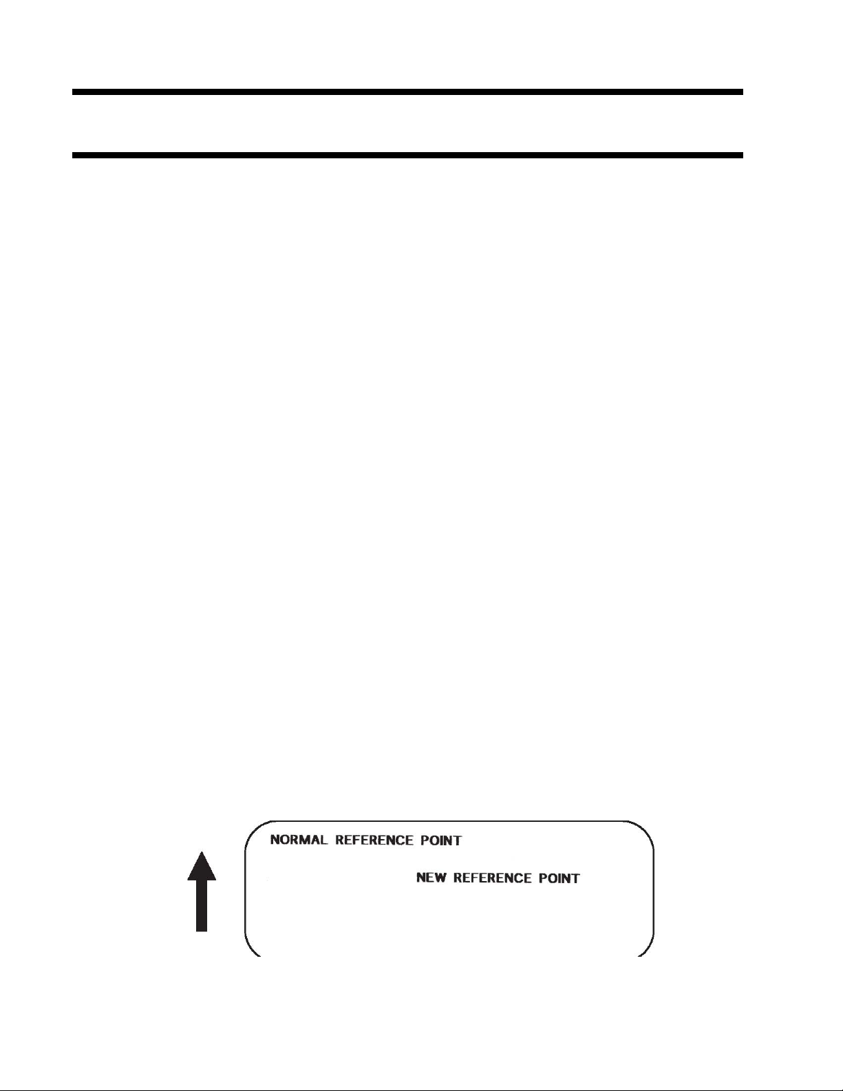
Base Reference Point
Command Structure <ESC>A3HabbbbVcdddd
a = - Specifies that the horizontal offset is in the negative direction.
+ Specifies that the horizontal offset is in the
positive direction.
bbbb = Horizontal Print Offset (see Note 5 for field range)
c = - Specifies that the vertical offset is in the
negative direction.
+ Specifies that the vertical offset is in the
positive direction.
dddd = Vertical Print Offset (see Note 5 for field range)
Example: <ESC>A3H+100V+0050
Placement: Preceding all images that are based on the new base reference point
Default: Current V and H offset setting in the printer configuration
Command Function To establish a new base reference point for the current label. The base
reference point is the top left corner or “origin” from where all print position
commands are based.
This command may be very helpful when using labels less than four inches
wide to place images on the printable label surface. It may also be used to
move images past preprinted fields on a label.
Input to Printer:
Printer Output:
<ESC>A<ESC>L0202 <ESC>H0100<ESC>V0025<ESC>XMNORMAL REFERENCE POINT
<ESC>A3H+0300V+0075 <ESC>H0100<ESC>V0050<ESC>XMNEW REFERENCE POINT
<ESC>Q1<ESC>Z
53
Page 63

Special Notes 1. Use of this command will set the Vertical/Horizontal Offset setting of the
printer configuration until a new Base Reference Point command is issued or
the setting is changed from the operator panel. See Section 2: Printer
Configuration.
2. This command may be used more than once in a print job.
3. An alternative to using this command is to make changes to your current
Horizontal and Vertical Print Position commands.
Example:
Let’s say the current base reference point is H=1, V=1 and you wish to move
all the fields on your label downward vertically by 150 dots. You could
either (1) add the Base Reference Point command or (2) change all the
vertical position commands by an additional 150 dots.
4. For a more detailed example of the Base Reference Point command, see
“Print Area” in this section.
5. The allowable field ranges for this command are:
Horizontal -0832 to 0832 -1248 to 1248
aaaa
Vertical -3200 to 3200 -4800 to 4800
bbbb
T400 T410
54
Page 64

Characters, Custom-Designed
Command Structure Store Command: <ESC>Tabcc Recall
Command: <ESC>Kab90cc
a = 1 16x16 matrix 2 24x24 matrix
b = Specifies the character encoding method for the data stream H
Hexadecimal characters B Binary characters
cc = Memory location to store/recall the character. Valid memory
locations are 21 to 52 (counting in Hex) or “!” to “R” in Binary
(data) = Data to describe the character
Example: <ESC>T1H3F <ESC>K1H903F See Appendix C for a more
detailed explanation
Placement: The Store command is typically sent in its own data stream to the
printer, between the Start/Stop commands. The Recall command is
sent in a secondary data stream to print the character,and follows any
necessary position or size commands.
Default: None
Command Function To allow for the creation, storage, and printing of custom characters, such as
special fonts or logos. Up to 50 individual characters may be stored in the
custom character volatile memory.
Printer Input See Appendix C for a detailed explanation.
<ESC>A <ESC>T1H3F
0100038007C00FE01FF03FF87FFCFFFE07C007C007C007C007C007C007C007C0 <ESC>Z
<ESC>A
<ESC>H150<ESC>V100<ESC>L0505<ESC>K1H903F
<ESC>H350<ESC>V100<ESC>L1010<E SC>K1H903F
<ESC>Q1<ESC>Z
55
Page 65

Printer Output
Special Notes 1. When printing the custom character using the Recall command, the character
is affected by the following commands:
Character Expansion
Character Pitch
Line Feed
Rotate, Base Reference Point Fixed
Rotate, Moving Base Reference Point
2. The characters are stored in volatile memory and must be reloaded if the
printer power is lost.
3. Do not use ASCII <CR> or <LF> characters (carriage return or line feed) as
line delimiters within the graphic data or the actual image will not be printed
as specified.
56
Page 66

Character Expansion
Command Structure <ESC>Laabb
aa = Multiple to expand horizontally (01-12)
bb = Multiple to expand vertically (01-12)
Example: <ESC>L0305
Placement: Preceding the data to be expanded
Default: <ESC>L0101
Command Function To expand characters independently in both the horizontal and vertical
directions. The command allows you to enlarge the base size of each font
(except the vector font) up to 12 times in either direction. Expanded characters
are typically used for added emphasis or for long distance readability.
Input to Printer
Printer Output
<ESC>A
<ESC>A<ESC>H0100<ESC>V0100<ESC>XMOKI
<ESC>H0100<ESC>V0200<ESC>L0402<ESC>XMOKI
<ESC>H0100<ESC>V0300<ESC>L0204<ESC>XMOKI
<ESC>Q1<ESC>Z
57
Page 67

Special Notes This command will expand the following fonts:
1. Fonts U, S, M, XU, XS, XM, OA & OB and fonts WB, WL, XB and XL.
2. This command will also affect the following commands: Character Pitch
Characters, Custom-Designed
3. The Character Expansion value is in effect for the current print job until a
new expansion command is specified.
4. The Line and Box command, if used within the data stream, may return all
subsequent text to the default expansion of 1 x 1. Therefore, either send the
Character Expansion command before all printed data, or send Line and Box
commands last, preceding the <ESC>Q Quantity command.
58
Page 68

Character, Fixed Spacing
Command Structure <ESC>PR
Example: See Above
Placement: Preceding the data
Default: The default is Proportional Spacing.
Command Function To reset proportional spacing and place the printer back to fixed spacing
Printer Input
Printer Output
<ESC>A
<ESC>H0025<ESC>V0050<ESC>PS
<ESC>L0202<ESC>XMPROPORTIONAL SPACING
<ESC>H0025<ESC>V0130<ESC>PR
<ESC>L0202<ESC>XMFIXED SPACING
<ESC>Q1<ESC>Z
Special Notes 1. This command only works with the proportionally spaced fonts XU, XM,
XS, XL and XB.
59
Page 69

Character Pitch
Command Structure <ESC>Paa
aa = Number of dots between characters (00-99)
Example: <ESC>P03
Placement: Preceding the text to be printed
Default: <ESC>P02
Command Function To designate the amount of spacing (in dots) between characters.
This command provides a means of altering character spacing for
label constraints or to enhance readability.
Input to Printer
<ESC>A<ESC>PS
<ESC>H0025<ESC>V0025<ESC>L0202<ESC>XBOKI
<ESC>H0025<ESC>V0125<ESC>L0202<ESC>P20<ESC>XB1OKI
<ESC>H0025<ESC>V0225<ESC>L0202<ESC>P40<ESC>XB1OKI
<ESC>Q1<ESC>Z
Printer Output
60
Page 70

Special Notes 1. This command is affected by the <ESC>L Character Expansion command.
The character pitch is actually the product of the current horizontal
expansion multiple and the designated pitch value.
Example:
<ESC>L0304
<ESC>P03
Pitch = (03) x (03) = 9 dots
2. To avoid confusion, you may want to include the <ESC>L Character
Expansion command and this command together in your program.
3. This command affects fonts U, S, M, XU, XS, XM, OA & OB, fonts WB,
WL, XB and XL, and the vector font.
4. Character Pitch will always revert to the default value unless it is specified
before each new font command in the data stream.
5. This command also affects Codabar, Code 39 and Industrial 2 of 5 bar
codes.
61
Page 71

Character, Proportional Spacing
Command Structure <ESC>PS Set to proportional spacing
<ESC>PR Reset to fixed spacing
Example: See above
Placement: Preceding data to be proportionally spaced
Default: <ESC>PS
Command Function To specify the printing of proportional or fixed spacing for proportionally
spaced fonts.
Printer Input
Printer Output
<ESC>A
<ESC>H0025<ESC>V0050<ESC>PS
<ESC>L0202<ESC>XMPROPORTIONAL SPACING
<ESC>H0025<ESC>V0130<ESC>PR
<ESC>L0202<ESC>XMFIXED SPACING
<ESC>Q1<ESC>Z
Special Notes 1. Once this command is sent in the data stream, it is in effect until the end of
the print job unless a reset command is sent.
62
Page 72

Clear Print Job(s) & Memory
Command Structure <ESC>*a
a = If the “a” parameter is not included with this command and the
a = If “a” is included with this command, it specifies the internal
Example: <ESC>*
printer is in the multi-buffer mode, this command clears all print jobs
in the printer memory, including the current print job.
memory section to be cleared
T To clear the custom character memory
& To clear the form overlay memory
X To clear all internal memory
<ESC>*X
Placement: This command should be sent to the printer as an independent data
stream.
Default: None
Command Function To clear individual memory or buffer areas of the printer.
Input to Printer
Printer Output There is no printer output as a result of this command. The current print job in
Special Note 1. It is not necessary to clear the printer’s memory between each print job.
2. The primary purpose of this command is to clear all print jobs in the
3. When the “a” parameter is used, the section of memory specified will not be
<ESC>A <ESC>*
<ESC>Z
the buffer will be terminated and all other print jobs in the buffer cleared.
multi-buffer mode. The “a” parameter can be used in either the multi-buffer
or single job mode to clear specific parts of the memory.
cleared until the label is printed.
63
Page 73

Continuous Forms Printing
Command Structure None
The printer locates the end of an adhesive label by sensing the backing
between labels or through the use of an eye-mark (black rectangle on the
reverse side of the backing). It locates the end of a tag from a notch, eye-mark,
or a hole between tags. Both sensors should be disabled when printing
continuous forms. See Configuration Commands at the end of this section for
information on using the <ESC>IG Sensor Select command. To change the
default setting to Continuous Forms Printing, use the <ESC>PG Printer Setting
command.
If you will be using continuous labels or tags, the printer must be told to stop
feeding in another manner. The length is determined by the position of the last
printed image on the label or tag. The printer will stop feeding when this last
field is finished printing. The length may be increased with printed spaces (20
hexadecimal) if necessary. There is no command code to control label length.
64
Page 74

Copy Image Area
Command Structure <ESC>WDHaaaaVbbbbXccccYdddd
aaaa = Horizontal position of the top left corner of the area to be copied
bbbb = Vertical position of the top left corner of the area to be copied
cccc = Horizontal length of the image area to be copied
dddd = Vertical length of the image area to be copied
Example: <ESC>WDH0100V0050X0600Y0400
Placement: Anywhere within the data stream, after specifying the
location of the duplicate image.
Default: None
Command Function To copy an image from one location to another on the same label.
This may be useful for duplicating individual fields or entire sections
of the label with only one command.
Input to Printer
Printer Output
<ESC>A
<ESC>H0050<ESC>V0050<ESC>E010<ESC>XM
OKIOKIOKIOKIOKI
OKIOKIOKIOKIOKI
OKIOKIOKIOKIOKI
OKIOKIOKIOKIOKI
<ESC>H0180<ESC>V0250<ESC>WDH0165V0050X0400Y0200
<ESC>Q1<ESC>Z
65
Page 75

Special Notes 1. Use the Print Position commands (V and H) to locate the new area for the
duplicate image.
2. Position of the new target area must not be inside the original image.
3. If you use the Rotate command, V, H, X and Y axes will be reversed.
4. If the reference area of the target image exceeds the print area, it will not be
printed.
5. The allowable ranges for these fields are as follows:
Horizontal 0001 0001
aaaa to to
cccc
Vertical 0001 0001
bbbb to to
dddd 3200 4800
T400 T410
0832 1248
66
Page 76

Cut Job
Command Structure <ESC><NUL>aaaa
<ESC>~aaaa
aaaa = Number of labels to print between each cut (1-9999)
Example: <ESC>~2
Placement: Following the Print Quantity command <ESC>Q
Default: <ESC>~1 (if cutter enabled)
Command Function To control the cutting of labels when using a OKI cutter unit with the printer.
This command allows the cutting of a multi-part tag or label at a specified
interval within a print job.
Input to Printer:
Printer Output: This set of commands will print 6 labels (3 x 2) with two labels between each
<ESC>A
<ESC>H0020<ESC>V0020<ESC>XB1ABC<ESC>Q3
<ESC>~0002
<ESC>Z
cut.
Special Notes 1. You must have the optional printer Cutter to use this function. Contact your
OKI representative for more information.
2. To use this command, the printer configuration must have the cutter option
enabled. See Printer Configuration commands in this section manual.
3. If the cutter option has been enabled in the printer configuration and the cut
value (a = 0), the cutter is inactive.
4. The <NUL> represents the ASCII 00 Hex character. A “~” (tilde) character
or <NUL> character can be substituted in this command.
5. When using the Cutter command, the total number of labels printed is the
product of the cut value and the print quantity.
67
Page 77

Cut
Command Structure <ESC>CTaaaa
aaaa = Number of labels to print between each cut (1-9999)
Example: <ESC>CT2
Placement: Preceding the <ESC>Q Print Quantity command.
Default: <ESC>CT1 (if cutter enabled)
Command Function To control the cutting of labels when using a OKI cutter unit with the printer.
This command allows the cutting of a multi-part tag or label at a specified
interval within a print job. It differs from the <ESC>~ Cut Job command in
that it does not interact with the quantity command.
Input to Printer:
Printer Output: This set of commands will print seven labels with two labels between each cut.
<ESC>A
<ESC>H0020<ESC>V0020<ESC>XB1ABC<ESC>T0002
<ESC>Q7<ESC>Z
One label will be left in the printer.
Special Notes 1. You must have the optional printer Cutter to use this function. Contact your
OKI representative for more information.
2. To use this command, the printer configuration must have the cutter option
enabled. See Configuration Commands in this section of the manual.
3. If the cutter option has been enabled in the printer configuration and the cut
value (a = 0), the cutter is inactive.
4. This command is independent of the <ESC>Q Quantity command. It will cut
the specified number of labels. If a printed label is left in the printer after the
last cut, the <ESC>YC Cut/Eject command can be used to cut it.
68
Page 78

Cut Last
Command Structure <ESC>YC
Example: <ESC>YC
Placement: Separate data stream sent to the printer
Default: None
Command Function To control the cutting of labels when using a SATO cutter unit with
Command Function To control the cutting of labels when using a OKI cutter unit with
the printer. This command allows the cutting of a printed multi-part
tag or label that is left in the printer after a job is cut using the
<ESC>CT Cut command.
Input to Printer:
Printer Output: This command will feed the last printed label to the cut position,
<ESC>A
<ESC>YC
<ESC>Z
cut the label and then backfeed to the head position in preparation
for printing the next job.
Notes 1. You must have the optional printer Cutter to use this function. Contact your
OKI representative for more information.
69
Page 79

Fonts U, S, M, OA, OB, XU, XS & XM
Command Structure Font XU: <ESC>XU Font U: <ESC>U
Font XS: <ESC>XS Font S: <ESC>S
Font XM: <ESC>XM Font M: <ESC>M
Font OA: <ESC>OA Font OB:<ESC>OB
Example: See above
Placement: Preceding the data to be printed
Default: None
Command Function To print text images on a label. These are eight of the built-in fonts available on
the printer. All matrices include descenders.
NON-PROPORTIONAL PROPORTIONAL
U 5W x 9H dot matrix XU 5W x 9H dot matrix
S 8W x 15H dot matrix XS 17W x 17H dot matrix
M 13W x 20H dot matrix XM 24W x 24H dot matrix
OA OCR-A font (see Note 7 for matrix)
OB OCR-B font (see Note 7 for matrix)
(1) These fonts will be printed with non-proportional spacing only if preceded by an <ESC>PR
command.
Input to Printer <ESC>A<ESC>PS
<ESC>H0025<ESC>V0100<ESC>L0202<ESC>XUOKI “XU”
<ESC>H0025<ESC>V0175<ESC>L0202<ESC>XSOKI “XS”
<ESC>H0025<ESC>V0250<ESC>L0202<ESC>XMOKI “XM”
<ESC>H0025<ESC>V0325<ESC>L0101<ESC>OAOKI “OA”
<ESC>H0001<ESC>V0400<ESC>L0101<ESC>OBOKI “OB”
<ESC>H0300<ESC>V0100<ESC>L0202<ESC>UOKI “U”
<ESC>H0300<ESC>V0175<ESC>L0202<ESC>SOKI “S”
<ESC>H0300<ESC>V0250<ESC>L0202<ESC>MOKI “M”
<ESC>Q1<ESC>Z
Printer Output
(1)
70
Page 80

Special Notes 1. Characters may be enlarged through the use of the Character Expansion
command.
2. Character spacing may be altered through the use of the Character Pitch
command. The default is 2 dots between characters. It is recommended to
use a spacing of 5 dots for OCR-A and 1 dot for OCR-B.
3. You may also create custom characters or fonts. See the <ESC>T
Custom-Designed Characters command.
4. A font must be defined for each field to be printed. There is no default font.
5. Fonts U, S, M, OA and OB are identical to fonts U, S, M, OA and OB on the
OKI M-8400 printer.
6. The proportionally spaced fonts XU, XS, XM, XL and XA can be printed
with fixed spacing using the <ESC>PR Fixed Space command.
7. The matrices for the OA and OB fonts are scaled so that they will remain a
constant size according to the OCR-A and OCR-B specifications when
printed on different resolution printers.
OA Font 15 dots W x 22 dots H 22 dots W x 33 dots H
OB Font 20 dots W x 24 dots H 30 dots W x 36 dots H
T400 T410
71
Page 81

Font/Graphic Recall
Command Structure <ESC>A<ESC>RFaabbbb,nn...n
aa = Font ID number (00 to 80)
bbbb = Number of characters to print (0000-9999)
nn..n = Data to be printed
Example: <ESC>RF010004,ABCD
Placement: Within normal command stream
Default: None
Command Function To recall fonts or graphic previously stored in the printer memory
using the Font/Graphic Store Utility Program.
Input to Printer
Printer Output
<ESC>A
<ESC>V0100<ESC>H0100
<ESC>RF010001,G
<ESC>Q1<ESC>Z
Label Sample TBA
Special Notes 1. To store or delete a graphic or font, the Font/Graphic Store Utility program
contained on the CD-ROM must be used.
2. To recall a graphic, the parameter “bbbb” must be “0001" and the ”nnn..n"
parameter must be a “G”.
3. To recall a stored font, the OKI OKIPOS T4XX Windows Driver should be
used.
72
Page 82

Font, Raster
Command Structure <ESC>A<ESC>RDabb,ccc,ddd,nn. . .n
a = A CG Times font style
B CG Triumvirate font style.
bb = 00 for Normal font
01 for Bold font
ccc = Horizontal size (16 -999 dots or P08 - P72)
ddd = Vertical size (16 - 999 dots or P08 -P72)
nn..n = Data to be printed.
Example: <ESC>RFA00,014,018ABCD
Placement: Within normal command stream
Default: None
Command Function To print point size characters created using font definitions.
Input to Printer
Printer Output
<ESC>A
<ESC>V0100<ESC>H0100
<ESC>RDA00,014,018ABCD
<ESC>V0200<ESC>H0100
<ESC>RFB10,018,014ABCD
<ESC>Q1<ESC>Z
Label Sample TBA
Not
Implemented
Special Notes 1. The “cccc” Horizontal Size and “dddd” Horizontal Size parameters can be
entered either in dots or points, but both parameters must use the same value
types. If point size is used, the point size is preceded by a “P”.
73
Page 83

Font, Vector
Command Structure Specify Vector Font: <ESC>$a,b,c,d
Data for Vector Font: <ESC>$=(data)
a = A Helvetica Bold (proportional spacing)
B Helvetica Bold (fixed spacing)
b = Font width (24-999)
c = Font height (24-999 dots)
d = Font variation (0-9) as follows:
0 Standard
1 Standard open (outlined)
2 Gray (mesh) pattern 1
3 Gray (mesh) pattern 2
4 Gray (mesh) pattern 3
5 Standard open, shadow 1
6 Standard open, shadow 2
7 Standard mirror image
8 Italic
9 Italic open, shadow
Example: <ESC>$A,100,200,0<ESC>$=123456
Placement: Immediately preceding data to be printed.
Default: None
Command Function To specify printing of the unique OKI vector font. The vector font allows large
characters to be printed with smooth, round edges. Each character is made of a
number of vectors (or lines), and will require slightly more printer compiling time.
Input to Printer
<ESC>A
<ESC>H0100<ESC>V0100<ESC>$A,100,100,0<ESC>$=OKI
<ESC>H0100<ESC>V0200<ES C>$=VECTOR FONT
<ESC>$A,200,300,8<ESC>H0100<ESC>V0350<ESC>$=OKI
<ESC>Q1<ESC>Z
74
Page 84

Printer Output
Special Notes 1. The Pitch command can be used with Vector fonts.
2. If the font size designation is out of the specified range, a default value of 50
is used.
4. The font width and height values include asenders, desenders and other
space.
5. A font must be defined for each field to be printed. There is no default font.
75
Page 85

Fonts WB, WL, XB & XL
Command Structure Font WB: <ESC>WBa Font XB: <ESC>XBa
Font WL: <ESC>WLa Font XL: <ESC>XLa
a = 0 Disables auto-smoothing of font
1 Enables auto-smoothing of font (see notes below)
Example: <ESC>WB1123456
Placement: Preceding the data to be printed
Default: None
Command Function To print text images on a label. These are the four auto-smoothing fonts available
on the printer.
NON-PROPORTIONAL PROPORTIONAL
WB 18W x 30H dot matrix XB 48W x 48H dot matrix
WL 28W x 52H dot matrix XL 48W x 48H dot matrix
(1) These fonts will be printed with proportional spacing only if preceded by an <ESC>PS
command.
Input to Printer ESC>A<ESC>PS
<ESC>H0001<ESC>V0100<ESC>WB0OKI “WB0"
<ESC>H0001<ESC>V0185<ESC>WB1OKI ”WB1"
<ESC>H0001<ESC>V0270<ESC>WL0OKI “WL0"
<ESC>H0001<ESC>V0355<ESC>WL1OKI ”WL1"
<ESC>H0400<ESC>V0100<ESC>XB0OKI “XB0"
<ESC>H0400<ESC>V0185<ESC>XB1OKI ”XB1"
<ESC>H0400<ESC>V0270<ESC>XL0OKI “XL0"
<ESC>H0400<ESC>V0355<ESC>XL1OKI ”XL1"
<ESC>Q1<ESC>Z
Printer Output
Not
(1)
76
Implemented
Page 86

Special Notes 1. Auto-smoothing (when enabled) is only effective if the character expansion
rate is at least (3) times in each direction.
2. Characters may be enlarged through the use of the <ESC>L Character
Expansion command.
3. Character spacing may be altered through the use of the <ESC>A Character
Pitch command.
4. A font must be defined for each field to be printed. There is no default font.
5. The proportionally spaced fonts XU, XS, XM, XL and XB can be printed
with fixed spacing using the <ESC>PS Proportional Space command.
6. The WB and WL fonts are not available in the initial production OKIPOS
T400/T410 printers. Please contact your OKI representative and make
arrangements to have your printer upgraded if these two fonts are not
present.
77
Page 87

Form Overlay, Recall
Command Structure <ESC>/
Example: <ESC>/
Placement: Must be preceded by all other data and placed just before
the Print Quantity command (<ESC>Q)
Default: None
Command Function To recall the label image from the form overlay memory for printing.
This command recalls a stored image from the overlay memory.
Additional or different data can be printed with the recalled image.
Input to Printer
Printer Output
<ESC>A
<ESC>H0001<ESC>V0125
<ESC>STHIS IS THE STORED IMAGE WITH A BARCODE
<ESC>H0001<ESC>V0165<ESC>B103100*12345*
<ESC>&<ESC>Z
<ESC>A<ESC>H0001<ESC>V0050
<ESC>STHIS IS RECALLING AND ADDING TO THE STORED IMAGE<ESC>/
<ESC>Q1<ESC>Z
Special Notes 1. The overlay is stored using the <ESC>& Form Overlay Store command.
2. Only one Form Overlay can be stored in the T4XX memory.
78
Page 88

Form Overlay, Store
Command Structure <ESC>&
Example: <ESC>&
Placement: Must be preceded by all other data and placed just before the Stop
command (<ESC>Z)
Default: None
Command Function To store a label image in the volatile form overlay memory. Only one label
image may be stored in this memory area at a time.
Input to Printer
<ESC>A
<ESC>H0001<ESC>V0125
<ESC>STHIS IS THE STORED IMAGE WITH A BARCODE
<ESC>H0001<ESC>V0165<ESC>B103100*12345*
<ESC>
&
<ESC>Z
Printer Output There is no output from this command. It stores the label image in the overlay
buffer.
Special Notes 1. Remember that this storage is volatile. Therefore, if the printer loses power,
the overlay must be sent again.
2. The overlay is recalled using the <ESC>/ Form Overlay Recall command.
3. Form overlays do not have to be recompiled each time they are called to be
printed and therefore may result in much faster print output.
4. The OKIPOS T400/T410 printers can only store one format.
79
Page 89

Graphics, Custom
Command Structure <ESC>Gabbbccc(data)
a = Specifies format of data stream to follow B Binary format H
Hexadecimal format
bbb = Number of horizontal 8 x 8 blocks (001-248)
ccc = Number of vertical 8 x 8 blocks (001-267)
(data) = Hex data to describe the graphic image
Example: <ESC>GH006006
See Appendix C for a detailed example
Placement: May be placed anywhere within the data stream after the necessary
position commands.
Default: None
Command Function To create and print custom graphics (logos, pictures, etc.) on a label. The
graphic image may be printed along with other printed data to enhance label
appearance or eliminate the need for preprinted label stock. Using a
dot-addressable matrix, design the graphic image in 8 dot by 8 dot blocks, then
send it in a binary format to the printer.
Printer Input
<ESC>A
<ESC>H0100<ESC>V0100<ESC>GH006006
FFFFFFFFFFFFFFFFFFFFFFFFC00000000003
C00000000003C000FFFFFFF3C00080000013
C00080000013C0009FFFFF13C00080000013
C00080000013C0009FFFFF13C00080000013
C00080000013C000FFFFFFF3C00000000003
C00000000003C00000000003C00000000003
C00000000003C00000000003C00003C00003
C00007E00003C0000FF00003C0000FF00003
C0000FF00003C0000FF00003C00007E00003
C00003C00003C00003C00003C00003C00003
C00003C00003C00003C00003C00003C00003
C00003C00003C00003C00003C00003C00003
C00003C00003C00001800003C00000000003
C00000000003FFFFFFFFFFFFFFFFFFFFFFFF
<ESC>H0300<ESC>V0100<ESC>XSPLEASE PLACE YOUR DISK
<ESC>H0300<ESC>V0150<ESC>XSIN A SAFE PLACE
<ESC>Q1<ESC>Z
See Appendix C for details on the data format.
80
Page 90

Printer Output
Special Notes 1. Do not use ASCII <CR> or <LF> characters (carriage return or line feed) as
line delimiters within the graphic data or the actual image will not be printed
as specified.
2. A custom graphic cannot be enlarged by the <ESC>L Character Expansion
command .
3. A custom graphic is not affected by either of the Rotation commands.
Therefore, always design and locate your graphic image to print in the
appropriate orientation.
4. The binary format reduces the transmission time by 50%.
81
Page 91

Job ID Store
Command Structure <ESC>IDaa
aa = Job ID assigned (01 to 99)
Example: <ESC>ID09
Placement: Immediately following the <ESC>A in the job data stream.
Default: None
Command Function To add an identification number to a job. The status of the job can then be
determined using the ENQ command in the Bi-Com status mode (See
Section 5: Interface Specifications for more information).
Printer Input
Printer Output There is no printer output as a result of this command. In the Bi-Com
Special Notes 1. Works only in Bi-Com mode. The Job ID number must be stored
2. If more than one ID number is sent in a single job, i.e.
the last number transmitted will be used.
<ESC>A
<ESC>ID02
. . . Job . . .
<ESC>Z
mode, the Job ID will be returned upon the receipt of a status
request command.
before Bi-Com status mode can be used.
<ESC>A
<ESC>ID01
..........
<ESC>ID02
.........
82
Page 92

Journal Print
Command Structure <ESC>J
Example: See above
Placement: Immediately following <ESC>A
Default: None
Command Function To print text in a line by line format on a label. By specifying this
command, you automatically select Font XS with a Character
Expansion of 2x2. You also establish a base reference point of
H2,V2. The character pitch is 2 dots and the line gap is 16 dots.
Simply issue an ASCII <CR> at the end of each text line.
Input to Printer
<ESC>A
<ESC>J WITH THE JOURNAL FEATURE
YOU CAN PRINT TEXT WITHOUT
USING ANY FONT COMMANDS
OR POSITION COMMANDS
<ESC>Q1<ESC>Z
Printer Output
Special Notes 1. Journal mode assumes a maximum label width . Otherwise, you may print
where there is no label and damage your print head.
2. It is effective only for the current print job.
83
Page 93

Lines and Boxes
Command Structure Line <ESC>FWaabcccc
aa = Width of horizontal line in dots (01-99)
b = Line orientation
H Horizontal line
V Vertical Line
cccc = Length of line in dots (see Note 2 for max length)
Box: <ESC>FWaabbVccccHdddd
aa = Width of horizontal side in dots (01-99)
bb = Width of vertical side in dots (01-99)
cccc = Length of vertical side in dots (see Note 2 for max length)
dddd = Length of horizontal side in dots
(see Note 2 for max length)
Example: <ESC>FW02H0200
Placement: Following the necessary positioning commands
Default: None
Command Function To print horizontal lines, vertical lines, and boxes as images on the label.
Input to Printer <ESC>A
<ESC>H0100<ESC>V0100<ESC>FW20H0200
<ESC>H0320<ESC>V0100<ESC>FW20V0200
<ESC>H0350<ESC>V0100<ESC>FW1010H0200V0200
<ESC>Q1<ESC>Z
84
Page 94

Printer Output
Special Notes 1. It is recommended that all lines and boxes be specified in the
normal print direction.
LINE/BOX T400 T412
LENGTH
Horizontal 0001 to 0832 0001 to 1248
cccc
Vertical 0001 to 3200 0001 to4800
cccc
2. The maximum allowable lengths for the different OKIPOS T400/T410
printers are as follows.
85
Page 95

Job Name
Command Structure <ESC>WKnnn...n
nn..n = Job Name assigned, up to 16 ASCII characters
Example: <ESC>WKOKI
Placement: Immediately following the <ESC>A in the job data stream.
Default: None
Command Function This command is to identify a particular job using a descriptive name
Printer Input
Printer Output There is no printer output as a result of this command. The information is
Special Notes 1. Works only in Bi-Com mode. The Job Name must be stored before Bi-Com
2. If more than one Job Name is sent in a single job, i.e.
the last name transmitted will be used.
<ESC>A
<ESC>WKOKI
. . . Job . . .
<ESC>Z
returned to the host upon receipt of a Bi-Com status request.
status mode can be used.
<ESC>A
<ESC>WKOKI
..........
<ESC>WKOKI AMERICA
.........
86
Page 96

Label/Tag Select
Command Structure <ESC>YEa
a = 0 Adhesive labels on liner
1 Tags
Example: See above
Placement: Separate data stream sent to the printer.
Default: Printer default setting
Command Function To select adhesive backed labels or non-adhesive tags
Input to Printer
Printer Output There is no printer output for this command
Special Notes 1. When power is recycled, the Label/Tag setting returns to the default value
2. This command is used to control last label printing. If Label is selected, the
<ESC>A
<ESC>YE0
<ESC>Z
specified by the <ESC>PG command. To change the default setting in the
printer, use the <ESC>PG Printer Configuration command or the Printer
Setting Utility program on the CD-ROM.
printer will stop printing as soon as a Label Out condition is detected. If Tag
is selected, the printer will continue to print after a Label Out signal is
detected until the current label is printed.
87
Page 97

Line Feed
Command Structure <ESC>Eaaa
aaa = Number of dots (001-999) between the bottom of the
characters on one line to the top of the characters on
the next line
Example: <ESC>E010
Placement: Preceding the text that will use the line feed function
Default: None
Command Function To print multiple lines of the same character size without specifying a
new print position for each line. With the Line Feed command, specify
the number of dots you want between each line. Then, send an ASCII
<CR> at the end of each line of text. The printer automatically
identifies the size of the last character, moves down the number of
dots specified, and begins printing the next line.
Input to Printer
<ESC>A
<ESC>E010<ESC>H0050<ESC>V0050<ESC>L0202<ESC>S
THIS IS THE 1ST LINE<CR>
THIS IS THE 2ND LINE<CR>
THIS IS THE 3RD LINE<CR>
<ESC>Q1<ESC>Z
Printer Output
Special Notes 1. This command can be used for text and for bar codes.
2. It is effective only for the current data stream.
3. When printing lines or boxes in the same data stream with the Line Feed
command, the Lines and Boxes command should be specified last, preceding
<ESC>Q Quantity command.
88
Page 98

4. This command is invalid only if the value specified is zero.
5. Following this command with a <CR> character will allow you to print with
auto line feed. In this case, the print position will be determined from the
value specified in the command and the H value set in the printer. However,
if you specify several H values after this command, the print position will be
determined by the H value last specified. You must redefine the font to be
used after each H command.
89
Page 99

Media Size
Command Structure <ESC>A1aaaabbbb
aaaa = Vertical Media Size in dots (0 to Vmax)
bbbb = Horizontal Media Size in dots (0 to Hmax)
Example: <ESC>A108323200
Placement: Separate data stream to the printer.
Default: <ESC>A108323200 for T400
<ESC>A108324800 for T410
Command Function To set the size of the media.
Input to Printer:
Printer Output: There is no printer output resulting from this command. It is used to
Special Notes 1. The Base Reference point is always on the right (looking at the front of the
2. If the label size is changed, then this command must be respecified to
3. All eight variables (“aaaa” and “bbbb”) must be included in this command.
<ESC>A
<ESC>A108323200
<ESC>Z
automatically adjust the offset values for the size of label being used.
printer) side of the print head. This command adjusts the Base Reference
Point to correspond with the right edge of the loaded media.
centralise the print image on the label.
90
Page 100

Off-Line
Command Structure <ESC>@
Example: See above
Placement: Anywhere in the print job between <ESC>A and <ESC>Z
Default: None
Command Function To specify the printer to come to an off-line state. When used within a print job,
the printer goes off-line after finishing the print job.
Input to Printer
Printer Output There is no printer output for this command. The printer is placed in the
Special Notes 1. You must press the LINE key on the front panel to return the printer to an
2. Remember, when using this command, that if the print job specifies
<ESC>A
<ESC>@
<ESC>Z
Off-Line mode as soon as the current print job is finished.
on-line status (see Operator Panel in Section 2 of this manual).
<ESC>Q10, all ten labels will print before the printer will go off-line.
91
 Loading...