

Page 1

Note To Customers
Every effort has been made to ensure that the information in this
document is complete, accurate and up-to-date. Mention of
software packages manufactured by other companies does not
necessarily constitute endorsement by OKI. We do not assume
responsibility for errors beyond our control, nor can OKI guarantee
that changes in the software and equipment made by other
manufacturers and referred to in this book will not affect the
applicability of information in this book.
© Copyright 1992 by OKI.
Epson is a registered trademark of Seiko Epson Corp.
IBM, IBM PC, PC XT and PC AT are registered trademarks of
International Business Machines Corp.
HELVETICA® is a registered trademark of Linotype AG and/or
its subsidiaries .
SWISS® is a trademark of Bitstream, Inc.
i
Page 2

Contents
Introduction .............................................................................. v
Important Note ......................................................................... vi
Selecting Drivers ..................................................................... vi
Chapter 1: Setup ....................................................................... 1-1
Preliminaries ........................................................................ 1-1
Optional Font Cartridges.................................................... 1-2
Connecting to Your Computer .......................................... 1-3
Inserting the Ribbon Cartridge .......................................... 1-5
Adjusting the Printhead Gap ............................................. 1-7
Installing the Paper Support .............................................. 1-8
Installing the Paper Separator ........................................... 1-9
Installing the Optional Tractor .......................................... 1-10
Installing the Optional Cut-Sheet Feeder......................... 1-14
Loading Rear Feed Continuous-Form Paper................... 1-17
Loading Single Sheet Paper ............................................... 1-19
Loading Bottom Feed Paper .............................................. 1-21
Loading the Cut-sheet Feeder............................................ 1-24
Printable area using the Cut-Sheet Feeder....................... 1-26
Printing Envelopes using the Cut-Sheet Feeder ............. 1-26
Printing on Continuous-Form Paper
with the CSF Installed ..................................................... 1-27
Setting the TOF/PARK ....................................................... 1-27
Paper Park ............................................................................ 1-29
Continuous-Form to Single Sheets .............................. 1-29
Single Sheet to Continuous-Form ................................ 1-29
Clearing Paper Jams ............................................................ 1-30
Running a Self Test.............................................................. 1-31
Information on Self-Test ..................................................... 1-32
ii
Page 3

Chapter 2: Operation ............................................................... 2-1
Using the Control Panel...................................................... 2-1
Basic Control ................................................................... 2-1
Print Characteristics ............................................................ 2-4
Font ................................................................................... 2-5
Print Quality.................................................................... 2-6
Using the Menu Select Mode ............................................. 2-7
Menu Selection ..................................................................... 2-9
Explanation of Menu Terms .............................................. 2-13
Cleaning ................................................................................ 2-17
Auto Fan Stop ...................................................................... 2-17
Problem Solving................................................................... 2-18
Chapter 3: IBM Control Code Reference ............................ 3-1
Character Format ................................................................. 3-1
Page Format.......................................................................... 3-10
Line Spacing ......................................................................... 3-13
Printing Features ................................................................. 3-16
Carriage Movement ............................................................ 3-21
Utility Commands ............................................................... 3-25
Chapter 4: Epson Control Code Reference ......................... 4-1
Character Format ................................................................. 4-1
Page Format.......................................................................... 4-7
Line Spacing ......................................................................... 4-11
Printing Features ................................................................. 4-14
Carriage Movement ............................................................ 4-21
Utility Commands ............................................................... 4-26
iii
Page 4

Chapter 5: Graphics ................................................................. 5-1
Control Codes for Graphics in Normal IBM Mode ........ 5-5
The IBM Alternate Graphics Mode ................................... 5-8
Epson Graphics Mode......................................................... 5-10
Programming in AGM and Epson Modes ....................... 5-11
Programming 24-pin Graphics .......................................... 5-12
Writing the Program ........................................................... 5-13
8-pin Graphics ...................................................................... 5-17
Reassigning Graphics Commands .................................... 5-17
Quasi 8-bit Graphics............................................................ 5-17
Print Registration ................................................................. 5-18
Chapter 6: Downloadable Characters .................................. 6 -1
Designing Characters .......................................................... 6 -1
Dot Assignments and Programming ................................ 6 -2
Defining a Character ........................................................... 6 -4
Epson Downloadable Characters ...................................... 6 -4
IBM Downloadable Characters ......................................... 6 -8
Appendix A: Control Code Tables ....................................... A-1
IBM Control Code Tables ................................................... A-1
Epson Control Code Tables................................................ A-10
Appendix B: ASCII Character Code Tables ....................... B-1
IBM Character Code Tables ............................................... B-1
Epson Character Code Tables ............................................ B-12
Appendix C: Interfacing ......................................................... C-1
Parallel Interfacing .............................................................. C-1
RS232-C Serial Interfacing .................................................. C-3
Local Tests: Serial Interface ................................................ C-4
Menu Selections for Serial Interfacing .............................. C-6
Appendix D: Specifications ................................................... D-1
iv
Page 5

Introduction
The Setup Guide will help you get your new printer set up and
running quickly. Here is how it is organised:
Setup shows you how to get the printer ready, connect it to
your computer, install the standard and optional paper
handling accessories, load different types of paper and run
a self test.
Operation describes how to run your printer using the
control panel and gives you some hints on what to do if you
are having problems.
If you want more details about working with software or advanced
topics like graphics, read Chapters 3 to 6. Use it to find out more
about particular commands or to explore your MICROLINEs
advanced capabilities.
In addition to this manual, make sure you have the following
items:
❿❿
❿
❿❿
➘➘
➘
➘➘
❡❡
❡
❡❡
➆➆
➆
➆➆
1. MICROLINE printer
2. Platen knobs (2) (fitted)
3. Power cord
4. Ribbon cartridge (black for ML393, colour for ML393C)
5. Paper support
*Paper and interface cable sold separately
v
Page 6

Important Note
If you are like most printer users you probably will not need to
read this entire book. Rather, you will flip from section to section
as required to learn how to make your printer do what you want
it to do. The Setup Guide contains information on loading paper
and most of the mechanical aspects of running your printer. The
Reference Guide pertains more to controlling your printers
features, such as format and print settings, and the method of
doing so.
● Chapters 3 and 4, IBM and Epson control code references, give
you the command codes and descriptions of their functions.
● Chapters 5 and 6 explain the particulars of writing commands
for generating graphics and designing your own characters.
● The Appendices provide you with code reference tables and
interfacing information, as well as other tables and technical
references you may require.
Selecting Drivers
Printer drivers are usually written for a particular model of printer
and identified by the name of that printer. Although most packages
offer several selections, they cannot have drivers for every printer.
Therefore, you may have to choose a driver that was not specifically
written for the ML393 but is compatible or nearly so. Installing a
driver is normally a simple process of making a selection from a
menu. Look for one of the following printers on your softwares
printer driver selection. As you go further down each list, you will
have access to fewer ML393 features.
vi
Page 7

IBM EMULATION EPSON
EMULATTION
OKI ML393 OKI ML393
IBM XL24/IBM 4207, 4208 EPSON LQ-1000 or
LQ-800
IBM PPR XL/IBM 4202 EPSON LQ-2500 (best
IBM PPR/IBM 4201 choice for colour
printing)
IBM GRAPHICS PRINTER/IBM 5152 Epson LQ-1500
Epson LQ
Epson FX
Epson JX
Epson LX
Epson RX
Epson MX
IMPORTANT
The wires in this mains lead are coloured in accordance with the following code:
GREEN AND YELLOW EARTH
BLUE NEUTRAL
BROWN LIVE
As the colours of the wires in the mains lead of this apparatus may not correspond
with the coloured markings identifying the terminals in your plug PROCEED
AS FOLLOWS:
The wire coloured GREEN AND YELLOW must be connected to the terminal
in the plug marked with the letter E or by the safety earth symbol or coloured
GREEN or GREEN AND YELLOW. The wire coloured BROWN must be
connected to the terminal marked with the letter L or coloured RED. The wire
coloured BLUE must be connected to the terminal marked with the letter N or
coloured BLACK.
WARNING: THIS APPARATUS MUST BE EARTHED
Ensure that your equipment is connected correctly. If you are in any doubt
consult a qualified electrician.
vii
Page 8

Chapter 1
Setup
Preliminaries
Open the access cover and remove the shipping restraint. (Save the
shipping restraint with the packaging materials).
The platen knobs should already be fitted to each side of the
printer. However, if they are removed for any reason, the flat side
of the shaft should be lined up with the flat side of the knob.
Setup 1 – 1
Page 9

Optional Font Cartridges
Insert cartridges with the label facing upwards; ensure that the
cartridge is firmly seated.
▲
Insert font cartridges here
Important: Ensure that the printer is turned off before inserting or removing font
cartridges.
1 – 2 Setup
Page 10

Connecting to Your Computer
Before you can use your printer, you need to attach it to your
computer using an interface cable.
Note: Interface cables are not supplied with the printer.
Interface cablePower cable
Microline 393 Printer (Rear view)
1. Make sure both your computer and your printer are switched
OFF.
2. Attach the power cord to the socket in the rear of the printer,
and plug it into an earthed power source.
Note: Do not use an unearthed adapter with your printer. The printer must be
connected to an earthed power supply.
Setup 1 – 3
Page 11

3. Plug the printer end of your interface cable into the connector
at the rear of the printer. Your printer has two interface ports.
Loosen the metal plate with a Phillips screwdriver and slide to
uncover the proper connector for the interface cable you are
using.
Serial interface Parallel interface
Tighten screw to
fasten cable
Note: Set the serial interface option in the menu so that it matches the printer
interface of your computer
Fasten clips to
cable
4. Connect the other end of your interface cable to the printer port
on your computer.
1 – 4 Setup
Page 12

Inserting the Ribbon Cartridge
IMPORTANT
You have just bought the best printer, so be sure to use the only
ribbons recommended for it. Original OKI ribbons are the only
ones recommended. Ask for them by name.
Please remember that if you buy any other ribbon your warranty
may be invalidated.
Purchasing inferior ribbons really does not make sense. They do
not last as long. They are prone to shredding, which can cause
damage to your printhead. That is why any short term savings on
cheaper ribbons are quickly lost.
So do not waste your time and money. Insist on OKI consumables
for your OKI printer.
You can order them from your printer supplier.
1. Unpack the ribbon cartridge. Remove the shipping restraint
and push the idler roller lock to the right to free the idler roller.
Takeup knob
Remove shipping restraint
Pin
ML393 Ribbon cartridge
Push to right to release
idler roller
Setup 1 – 5
Page 13

2. Open the printer access cover.
3. Centre the printhead.
Note: The printhead can get very hot during extended periods of printing—be
sure to let it cool off before you touch it.
4. Place the ribbon into the printer so that the pins on the ribbon
cartridge fit into the notches in the side plates of the printer.
Push down so that the cartridge snaps into position.
Centre the printhead
5. Thread the ribbon around the posts on the printhead, making
sure that you follow the proper path (refer to the following
illustration).
Thread ribbon around posts as shown
ML393C ML393
6. Turn the take-up knob clockwise to take up any ribbon slack.
1 – 6 Setup
Page 14

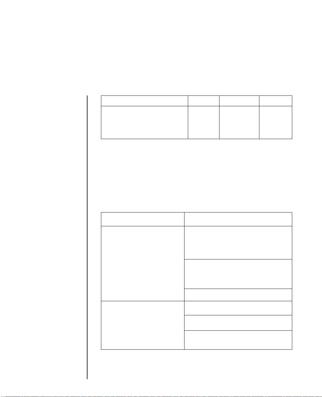
Adjusting the Printhead Gap
The blue head gap lever (located on the righthand side of the
printer, below the access cover) adjusts the printhead for printing
on different types of paper. The following are recommended
settings for commonly used papers. You may want to try varying
the settings to get the easiest feeding and best print quality for the
paper you are using.
Single part paper
Multiple part paper
(pressure - sensitive
paper, carbon - lined
paper)
Multiple part paper
(interleaf paper)
Labels
Envelopes
Ream weight
45-75 g/m2 (12-15 lb)
75-90g/m2 (20-24 lb)
2 part
2
35-40g/m
(9-11 lb)
38-45g/m
(10-12 lb)
3 part
4 part
2 part
2
3 part
4 part
Lever position
12345 6 789
Headgap lever
Important: The incorrect setting of the printhead gap lever can cause printhead
damage or ribbon jams. To avoid these problems set the printhead gap for the
type of stationery being used.
Setup 1 – 7
Page 15

Installing the Paper Support
Paper support
Holes pop
into tabs
on the
rear cover
1 – 8 Setup
Brace holds support upright
for single sheets of paper
Page 16

Installing the Paper Separator
The paper separator is fitted at the factory. These instructions are
supplied should it have had to have been removed.
Opens to prevent paper from curling back into the printer
Place the front end in first, then lower
Paper separator
the back and snap it into position
Setup 1 – 9
Page 17

Installing the Optional Tractor
This option lets you feed continuous-form paper from the bottom
of the printer. Use bottom feed for labels and other speciality
papers that have problems wrapping around the platen, as well as
for normal continuous-form paper.
To feed continuous paper from the bottom of the printer you need:
● The optional pull tractor kit.
● A slotted printer stand.
Acoustic cover
Paper guide
Pull tractor
1. Remove the paper separator by tilting it forwards and lifting it
out.
Open rear coverOpen bail
Move paper lever forwards
1 – 10 Setup
Page 18

2. Open the rear cover and the front access cover.
3. Pull the bail arm forwards.
4. Pull the paper lever forwards.
5. Lower the tractor on to the printer, fitting the tabs on the tractor
into the notches on the printer.
6. Pull forwards on the top of the tractor until it clicks into place
on the printer platen shaft. (To remove the tractor press the
locking buttons and tilt back.)
Clamp
Setup 1 – 11
Page 19

7. Push the bail arm back.
8. Close the rear cover. Fit the front tabs of the acoustic cover into
the slots on the sides of the rear cover, then tilt into place.
Tab fits into slots
9. Fit the tabs on the paper guide into the notches on the rear
of the acoustic cover.
1 – 12 Setup
Page 20

10. Close the front cover. The acoustic cover fits over the acoustic
shield on the front cover.
Acoustic cover
Setup 1 – 13
Page 21

Installing the Optional Cut-Sheet Feeder
The CSF 3001 single-bin and CSF 3002 dual-bin Cut-Sheet Feeders
(CSF) are ideal for high volume printing using single sheet paper.
Paper can be fed automatically, controlled either by the control
panel or through your computer. The dual-bin allows you to
alternate between letterhead and plain stationery.
Since the two CSF are installed in the same way, we will illustrate
the procedure with the CSF 3001, noting any differences as they
appear.
CSF 3001
Output tray
Bin racks
CSF 3002
1 – 14 Setup
Output tray
Bin racks
Page 22

1. Open the printer cover.
2. Remove the rear cover: tilt the cover slightly lift it up and off the
printer.
Remove rear cover.
3. Pull the bail arm forwards.
4. Fit the hooks on the CSF over the platen shaft and gently lower
on to the printer.
CSF hooks on to platenBail lever forwards
Setup 1 – 15
Page 23

5. Close the access cover.
6. Plug the CSF cable into the socket on the rear of the printer. The
arrow on the plug should point upwards.
7. Slide the output tray into the channels on the sides of the CSF.
8. Fit the wire rack into the holes in the back of the CSF paper bin.
9. Push the bail arm back.
1 – 16 Setup
Wire racks
Channels
Paper lever back
Page 24

Loading Rear Feed Continuous-Form Paper
When printing on rear feed continuous form paper use the builtin tractor.
1. Open the rear cover.
2. Move the centre paper guides to the middle of the paper.
Rear cover Paper guides
3. Insert the paper through the gap below the rear cover and pull
through.
Insert paper Pull paper through
Setup 1 – 17
Page 25

4. Move the left hand tractor to the required position. (Pull the
lever forwards to unlock the tractor and slide to adjust. Push
the lever back to lock.)
5. Open the tractor covers and set the first two sprocket holes on
the paper on the tractor pins.
Tractor cover
Lever
6. Adjust the right hand tractor to the width of the paper.
7. Close the tractor covers.
8. Close the rear cover.
9. Pull the paper lever forwards (to the continuous paper symbol).
10. Turn the printer ON. Press the FORM FEED button to advance
the paper to the front of the printer.
11. Set the PARK/TOF, refer to Setting the PARK/TOF described
in this chapter, to your requirements and you are ready to
print.
1 – 18 Setup
Page 26

Loading Single Sheet Paper
(No paper handling options installed)
1. If you have continuous-form paper in the printer, use the paper
park feature to back it out of the printer.
With SELECT LIGHT on, press the TOF/PARK button. The
paper will retract from the front of the printer.
2. Push the paper lever back to the single sheet setting (towards
the back of the printer).
3. Raise the paper support to its upright position.
Reference mark for left
Paper
edge
Paper lever backFORM FEED button
4. Place a sheet of paper on the support and adjust the guides for
the width of the paper you are using. Start with the reference
mark for the left edge.
Setup 1 – 19
Page 27

5. Press the FORM FEED button to insert the paper into the
printer.
6. Adjust the TOF if necessary. Refer to Setting the PARK/TOF
described later in this chapter.
1 – 20 Setup
Page 28

Loading Bottom Feed Paper
You can feed continuous-form paper from the bottom of the
printer when you have the optional pull tractor installed.
Open acoustic
cover
Pull bail lever
forwards
Optional tractor unit Pull paper lever
forwards
Slide paper guide to middle
of paper width
Open front cover
1. Open the acoustic cover on the pull tractor.
2. Open the printer access cover.
3. Pull the bail lever forwards.
4. Pull the paper lever for wards (to the continuous paper symbol).
5. Move the centre paper guides to the middle of the of the paper.
6. Push the paper up through the slot in the bottom of the printer
and pull it up in front of the platen to the tractor.
Setup 1 – 21
Page 29

7. Move the left hand tractor to the required position. (Pull the
lever forwards to unlock the tractor and slide to adjust. Push
the lever back to lock.)
8. Open the tractor covers and set the first two sprocket holes on
the paper on the tractor pins.
Tractor cover
Lever
9. Adjust the right hand tractor to the width of the paper.
10. Close the tractor covers.
11. Push the bail lever back.
12. Close the printer access cover and the tractor acoustic cover.
Important: The front cover must be closed for the printer to operate.
1 – 22 Setup
Page 30

Wind paper through Close front cover first then
acoustic cover
13. Set the PARK/TOF, refer to Setting the PARK/TOF for your
requirements and you are ready to print.
Setup 1 – 23
Page 31

Loading the Cut-Sheet Feeder
Each bin of the CSF 3001 and CSF 3002 holds up to 130 sheets of
20lb. paper, or between 100 and 120 sheets of 24lb. paper, depending
on the thickness and texture.
Note: Be sure to set the head gap lever for the type of paper that you are using.
Put letterhead stationery in with the letterhead facing down and towards the
printer.
Reset lever
Envelope lever
Paper lever
Insert paper in bin
Adjust guides to width of paper
1. Fan the paper and square it.
2. Pull the reset lever up to the RESET position.
3. Put the paper into the bin.
4. Adjust the guides to the width of the paper.
5. Ensure that the envelope lever is forwards in the paper position.
6. Push the reset lever down to the SET position.
7. Ensure that the paper lever is pushed back to the single sheet
setting (towards the back of the printer).
1 – 24 Setup
Page 32
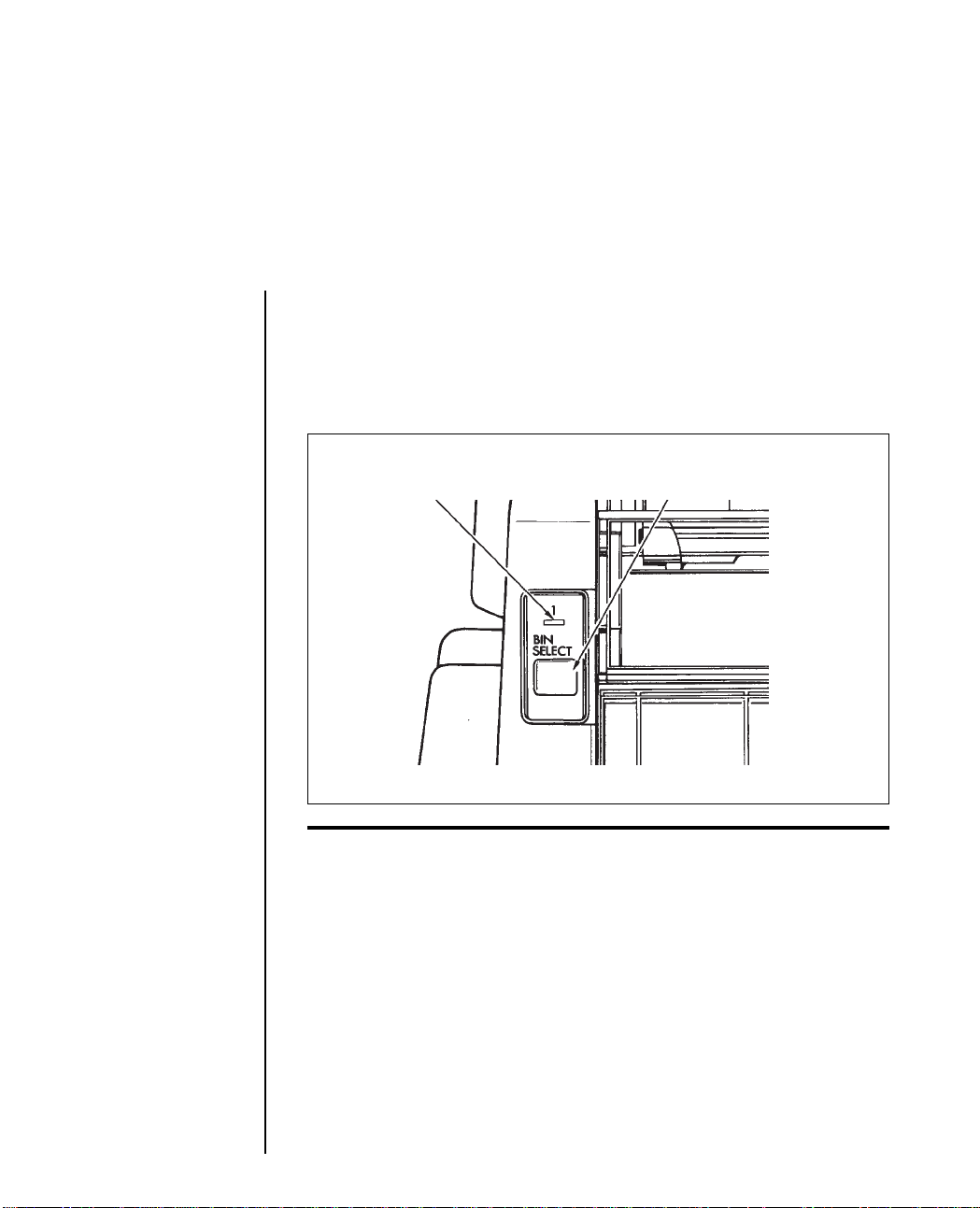
7. CSF 3002: To select the bin that you wish paper to be fed from
deselect the printer and press the BIN SELECT button on the
CSF. When the BIN SELECT light is ON, BIN 1 is selected,
when it is OFF, BIN 2 is selected. BIN 1 is the default selection
when the printer is switched ON.
Select bin 2 by pressing the
Bin 1 selected when light is ON
BIN SELECT button.
The light will go out
Note: This button has no function on the CSF 3001.
8. Press the FORM FEED or LINE FEED button to insert a sheet
of paper.
9. Adjust the TOF if necessary. Refer to Setting the PARK/TOF.
10. To insert a new sheet of paper, press the FORM FEED button.
Setup 1 – 25
Page 33

Printable Area Using the CSF
The default top margin when using the CSF is 1 inch. However,
paper can be fed to the top of the page using the reverse line feed
command to allow printing in this margin.
0.17”
Additional areas available
for printing but not
recommended because
of non-guarantee of
print quality,
paper skewing
and acoustic levels.
0.17”
▲▲
▼
▲
▼
▲
▲
0.39”
▲
0.39”
1” Top
Margin
▼
Recommended
printable area
▲
1” bottom
margin
▼
▲
Printing Envelopes with the CSF
You can use # 10 envelopes (standard business size) in your CSF
3001 and in the front bin only of the CSF 3002. Make sure that you
adjust the blue head gap lever to the correct setting and push the
envelope lever on the CSF back to the envelope symbol. Load
envelopes with the flaps facing down and towards the front of the
printer.
1 – 26 Setup
Page 34

For best results avoid printing on areas where the flap overlaps the
envelope. Printing where the envelope varies in thickness may be
uneven.
Printing on Continuous-Form Paper with the
CSF Installed
If you use single part continuous-form paper you can leave the
CSF installed on your printer and alternate between printing on
continuous-form paper or sheets from the CSF. Use the paper park
feature, described in the following pages, to select the form you
wish to print upon.
When paper is moved forwards to the print position from the park
position in the continuous-form mode, the FORM FEED button
must be used.
This method of alternating between forms is not recommended
when multipart continuous-form paper is used.
Setting the PARK/TOF
This establishes the position of the first print line on each page. The
red line on the ribbon shield shows the baseline of the current
position and helps you place the TOF where you want it.
If you are using a word processor that sets its own top margin, set
the TOF for the topmost line on the page. Otherwise we recommend
positioning the top of the page under the bail; the first line of
printing will then be about one inch from the top of the page.
Setup 1 – 27
Page 35

Red line shows baseline
for printing
Bail
1. Press the FORM FEED button to advance the paper into the
printer.
2. Press the SELECT button so that the SELECT light goes out.
3. Continuous-form paper: Use the platen knob to move the
paper to the correct position.
Single Sheets: Hold down the PARK/TOF button and press:
LINE FEED to move up the page, or FORM FEED to move
down the page. This allows you to move the paper in increments
of 1/180 inch so you can position the TOF precisely on single
sheets.
4. Press the PARK/TOF button to the set position.
5. Press the SELECT button to select the printer.
1 – 28 Setup
Page 36

Paper Park
Switching between continuous-form paper and single sheet paper
is particularly easy with your printer. Its automatic parking feature
allows you to back continuous-form paper out of the paper path
at the touch of a button, and at the touch of another button
automatically positions a single sheet. The paper park feature also
works when you have an optional CSF installed on your printer.
Continuous-form to Single Sheets
1. Make sure that the SELECT light is ON and press the PARK/
TOF button. The continuous-form paper will retract from the
paper path.
2. Push the paper lever back (to the single sheet setting).
3. Press the FORM FEED button to advance a sheet into the
printer.
Single Sheet to Continuous-form
1. If there is a sheet in the printer, press the FORM FEED button
to eject it.
2. Pull the paper lever forwards (to the continuous-form setting).
3. Press the FORM FEED button to advance the continuous-form
paper to the front of the printer.
Setup 1 – 29
Page 37

Clearing Paper Jams
In the unlikely event that you experience paper jams while using
either continuous-form paper or single sheets, the following
guidelines explain in detail the correct procedure for the removal
and resetting of the jammed paper.
1. Turn the printer OFF.
2. Open the access cover and set the head gap lever to the
maximum setting 9.
3. Tear the paper off at the position of the push/pull tractor if you
are using continuous form paper.
4. If paper is jammed at the ribbon protector, move the printhead
assembly away from the jam carefully (ensure that there is no
paper between the ribbon protector and the platen) and turn
the platen knob to feed the remaining paper out of the front of
the printer. If the paper jam occurs before the ribbon protector,
turn the platen knob so that the paper retracts along its loading
path.
5. Clear the paper path and ensure that there are no scraps of
paper left in the paper’s loading path or the printer.
6. Reset the head gap lever to the required position.
7. The printer is now ready for use.
Warning: Do not remove or loosen the ribbon protector screws at any time, as
the protector is fixed at a precise setting.
1 – 30 Setup
Page 38
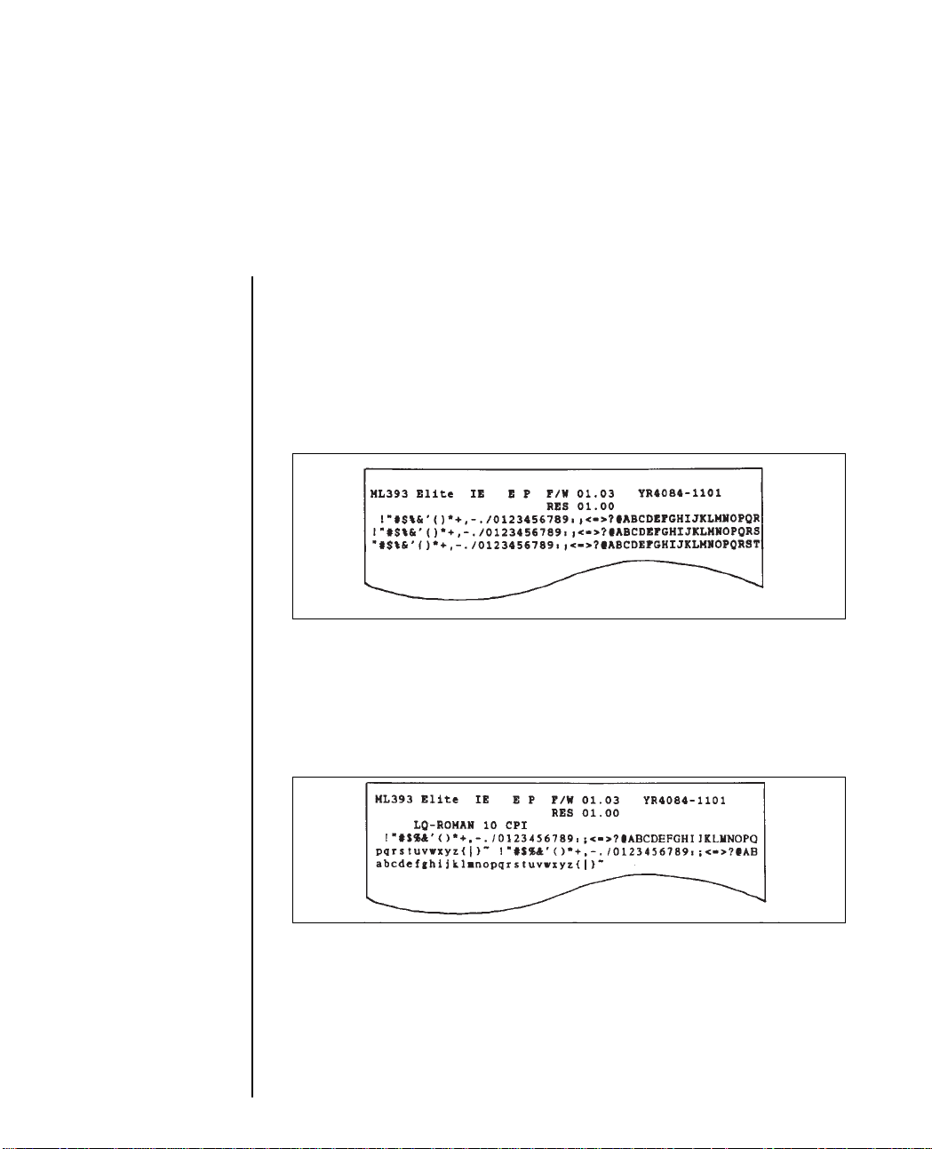
Running a Self Test
After you have installed the ribbon and loaded paper, you are
ready to run either of the two self tests. These tests allow you to
check that your printer is functioning properly.
Holding down the PARK/TOF button while switching the printer
ON produces:
A continuous sample of the default print style. This sample prints
along the entire length of the platen, so be sure to use wide paper
when running this test.
Holding down the LINE FEED button while turning the printer
ON produces:
A limited sample of each available print style. When complete
(about three pages), the printer stops and the SELECT light goes
out.
To terminate either of these two self-tests, press the SELECT
button. This will return the printer to its ready state and the
SELECT light will be lit.
Setup 1 – 31
Page 39

Information on the Self Test
ML393 ELITE I E E P F/W 01.00 YRXXXX-XXXX
Model Emulation Model Interface Firmware
for P = Parallel revision
Europe S = Serial number
RES 01.00
Have this information at hand if you call for service.
1 – 32 Setup
Page 40

Chapter 2
Operation
Using the Control Panel
The control panel puts many of your printers functions within
reach of your fingertips. It even lets you customise your printer for
special applications without programming. Experiment with these
controls and you will see how much your printer can do and how
easy it is to use. The next few pages explain the basics of using the
control panel.
Basic Controls
POWER light: Lit when On.
ALARM light: Lit to indicate alarm condition: paper out, paper
jam, cover open.
QUIET light: Lights when printer is operating in the quiet mode.
QUIET button: Pressing this button when the printer is selected
turns quiet mode on and off. This reduces printing noise in Letter
Quality (LQ) and Utility (UTL) modes.
When the printer is deselected, this button puts the printer into the
Menu mode.
LINE FEED button: Moves paper up one line (when printer is
selected or deselected). If a CSF is installed on the printer, pressing
the LINE FEED button will cause a single sheet to be inserted when
there is no paper is in the printer.
Operation 2 1
Page 41

FORM FEED button: Advances paper to the top of the next page
(when printer is selected or deselected).
PARK/TOF button: When the printer is deselected this button sets
the position of the first print line. When the printer is selected and
continuous-form paper is loaded, this button activates the
automatic paper park feature.
When single sheets are inserted holding down the TOF/PARK
button, and pressing the LINE FEED button allows you to move
up the page in increments of 1/180 inch to set the TOF, while
pressing the FORM FEED button allows you to move down the
page.
SELECT button: Selects or deselects the printer. When selected,
the printer is ready to receive data; when deselected, it will not
print. Pressing this button during a self-test will terminate the test
and return the printer to its ready state.
SELECT light: Lights when printer is selected (ready to receive
data); goes out when it is deselected. The light blinks when the
printer is in Print Suppress mode (refer to the Menu Settings for
more details).
FONT: Selects the typeface that the characters will be printed in.
PRINT QUALITY: Selects the quality of print of the typeface.
CHARACTER PITCH: Selects the size of the printed characters.
The following buttons have special functions when you hold them
down while turning the printer on:
QUIET: Activates the Menu Select Mode.
LINE FEED: Activates the print samples self-test.
PARK/TOF: Activates the continuous self-test.
FORM FEED: Puts the printer into the Menu Select Mode.
2 2 Operation
Page 42

SELECT and FORM FEED: Puts the printer into the Hex Dump
Mode.
SELECT and TOF/PARK: Returns the printer to the default Menu
settings.
QUIET and LINE FEED: Returns the paper loading position to the
default setting.
Button Functions in Menu Select Mode
When the printer is in the menu select mode, the features listed
below the buttons are activated.
PRINT: Prints the current menu settings.
GROUP: Switches between the broad menu categories.
ITEM: Displays the features contained in each of the categories.
SET: Selects and stores the options available for each feature in the
menu.
EXIT: Exits from the menu select mode and returns the printer to
its ready state. The buttons are returned to their basic functions.
Operation 2 3
Page 43

Print Characteristics
The font, print quality and character pitch buttons let you control
basic printing features through your printers control panel:
1. Press the SELECT button (SELECT light goes out).
2. Press the features that you wish to change (light goes on).
Note: If all the lights on the PRINT QUALITY section of the panel are out, the
printer will print in the High Speed Draft (HSD) Mode.
3. Press the SELECT button.
The panel always indicates the actual settings of the printer. If you
change any of these features through your software, the panel
lights will also change to reflect this feature choice.
The panel will only allow you to select valid combinations of
features. For example, proportional spacing can only be selected
when the print quality choice is set to LQ. Similarly CART cannot
be selected on the control panel unless a font cartridge is installed
in the FONT slot. The three printing features available on the
control panel offer the following selection of modes:
2 4 Operation
Page 44

Font
There are eight combinations of font which can be selected on your
printer, six resident fonts, a cartridge font and a downloaded font.
The resident fonts are:
COURIER: Selected when the COURIER light is lit.
ROMAN: Selected when the ROMAN light is lit.
PRESTIGE: Selected when the COURIER and SWISS lights are lit.
GOTHIC: Selected when the ROMAN and BOLD lights are lit.
SWISS: Selected when the SWISS light is lit.
SWISS BOLD: Selected when the BOLD light is lit.
CART: Selects the font from the optional cartridge, if installed.
Selected when the COURIER and ROMAN lights are lit.
DLL: Selects a font downloaded from the computer. Selected
when the SWISS and BOLD lights are lit.
Operation 2 5
Page 45

Print Quality
LQ: The Letter Quality mode produces crisp, clean characters,
almost like a typewriter. Print in LQ when you want your
correspondence and reports to look especially polished. You can
use LQ mode to print 10, 12, 15, 17.1 and 20 Characters Per Inch
(CPI), as well as proportional spacing.
NLQ: Near Letter Quality printing is faster than LQ, and produces
characters that are almost as sharp as Letter Quality. NLQ is
available in 10 and 12 CPI.
UTILITY: The Utility mode is ideal for high-volume printing. It is
much faster than LQ or NLQ, but the printed output is not as dense
as the higher-quality modes. Utility mode supports all the character
pitches with the exception of proportionally spaced text.
HSD: High Speed Draft is the fastest of the print modes. Use it for
quick printouts of long documents. High Speed Draft is only
available at 15 and 17.1 CPI.
CHARACTER PITCH (width selections)
10, 12,15, 17.1 and 20 CPI. Proportional spacing is also available for
use with resident LQ printing only.
Note: Pitches available with downloaded or cartridge fonts are font dependent.
Print quality and pitch combinations are available as described above.
2 6 Operation
Page 46

Using the Menu Select Mode
The Menu Select mode gives you fingertip control over some of
your printers most important features. Menu selections are chosen
while in the Menu Select mode and retained in the printers nonvolatile memory. In effect your settings become the default settings,
although they can be changed through software commands,
through the control panel or through resetting the menu.
Note: You can override features set on the menu using either the control panel
or commands sent from your computer. However, when you turn off the printer,
features set by those methods will be cancelled. Features set on the menu will stay
in effect, even when the printer is unplugged.
Entering the Menu Select Mode
Make sure that the printer is loaded with ribbon and paper.
Switch the printer ON while pressing the QUIET button in. If the
printer is already on and the SELECT light is off, press the QUIET
button. The functions listed underneath the buttons become active.
If you press the PRINT button, the current menu will be printed in
its entirety. It lists all the currently selected print features.
If you press the GROUP button, you can progress through the
broad menu categories until you reach the category that you want
to change.
Pressing the ITEM button allows you to select the feature of each
category that you want to change.
Pressing the SET button lets you make the final selection for each
item of the group.
Operation 2 7
Page 47

When you have made all the changes that you want, press the
EXIT button to store the changes and to return to the print mode.
The SELECT light will light to show that the printer is ready to
print, and the control panel will indicate any changes that you
made to the default settings while in the menu mode.
Note: If in the middle of the Menu Select mode you should run out of paper, the
red alarm light on the control panel goes on and the printer goes off line. Reload
paper and continue by pressing the SELECT button; the printer then resumes its
function in the Menu Select mode.
2 8 Operation
Page 48

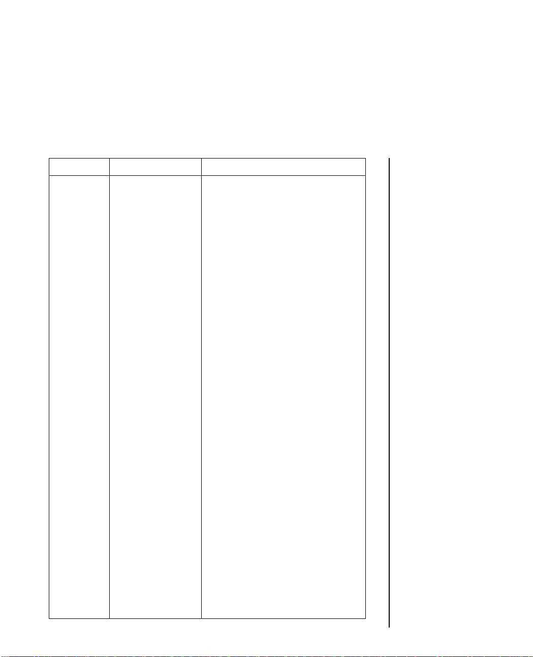
Menu Selections
NOTE: Factory default settings are pnnted in bold.
Group Item Selections
FONT PRINT MODE LQ, NLQ, UTILITY, HSD
TYPE STYLE COURIER, SWISS, SWISS BOLD,
ROMAN, LETTER GOTHIC,
PRESTIGE ELITE, CARTRIDGE,
DLL
PITCH 10CPI, 12CPI, 15CPI, 17.1CPI,
20CPI, PROPORTIONAL
STYLE NORMAL, ITALICS
SIZE SINGLE, DOUBLE, TRIPLE
SMOOTHING NO, YES
GENERAL EMULATION EPSON LQ, IBM PPR,
CONTROL MODE IBM X24 AGM
GRAPHICS UNIDIRECTIONAL,
BIDIRECTIONAL
MAX RECEIVE 8K, 23K, 40K (OPTION), 1 LINE
BUFFER
PAPER OUT NO, YES
OVERRIDE
PRINT 0, -1 -2, -3, -4, -5, +5, +4, +3, +2,
+1 REGISTRATION
OPERATOR FULL OPERATION, LIMITED
PANEL OPERATION
FUNCTIONS
RIBBON MAGENTA, CYAN, VIOLET,
SELECTION ORANGE, GREEN, BLACK
RIBBON, BLACK, YELLOW
Operation 2 9
Page 49
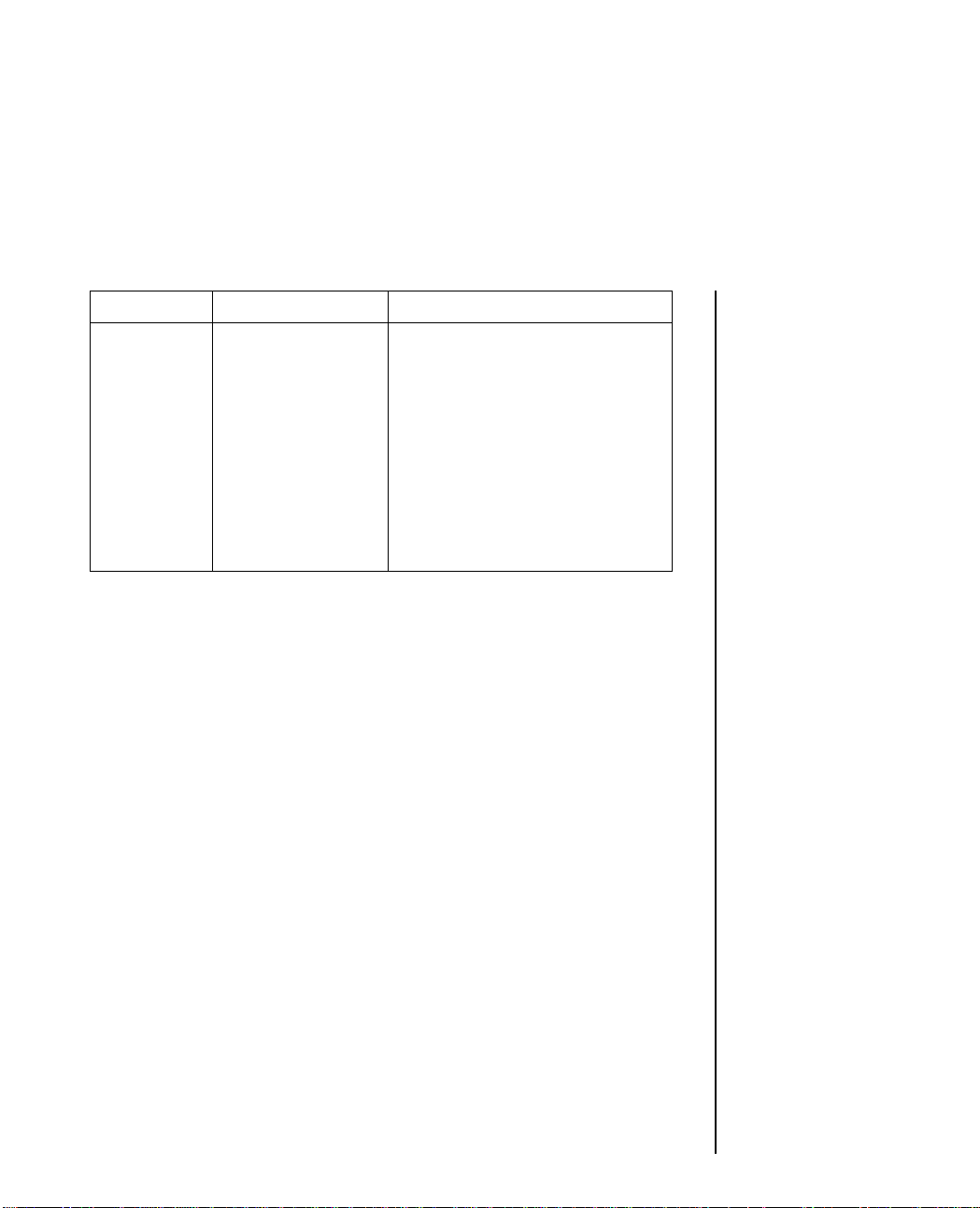
Group Item Selections
RESET INHIBIT NO, YES
PRINT SUPPRESS YES, NO
EFFECTIVE
PAGE WIDTH 13.6", 8"
CPU STANDARD, SPEClAL
COMPENSATION
VERTICAL LINE SPACING 6 LPI, 8 LPI
CONTROL
FORM TEAR OFF OFF, 300ms, 2 SEC, 4 SEC,
OFFLINE
SKIP OVER NO, YES
PERFORATION
AUTO LF NO, YES
AUTO CR (IBM) NO, YES
AUTO FEED XT INVALID, VALID
(EPSON)
FORM LENGTH INCHES, LINES
BASE
2 10 Operation
PAGE LENGTH 12", 11", 11 2/3", 14", 17", 3", 3.5",
(INCHES) 4", 5.5", 6", 7", 8", 8.5"
PAGE LENGTH 0, 1
(LINES*100)
PAGE LENGTH 7, 8, 9, 0, 1, 2, 3, 4, 5, 6
(LINES * 10)
PAGE LENGTH 2, 3, 4, 5, 6, 7, 8, 9, 0, 1
(LINES * 1)
SHEET PAGE 11 2/3", 14", 16.57", 3", 3.5", 4",
LENGTH 5.5", 6", 7", 8", 8.5", 12", 11"
Page 50

Group Item Selections
MENU LINE 6, 1
SYMBOL CHARACTER SET SET II, EPSON, SET I
SETS
CODE PAGE USA, MULTILINGUAL,
NORWAY, PORTUGAL,
TURKEY, GREEK 928*,
GREEK 851*, GREEK 437*
LANGUAGE SET ASCII, FRENCH, GERMAN,
BRITISH, DANISH I,
SWEDISH I, ITALIAN,
SPANISH I, JAPANESE,
NORWEGIAN,
DANISH II, SPANISH II,
LATIN AMERICAN,
FRENCH CANADIAN,
DUTCH, SWEDISH II,
SWEDISH III, SWEDISH IV,
TURKISH, SWISS I, SWISS II,
PUBLISHER
ZERO UNSLASHED, SLASHED
CHARACTER
SLASHED LETTER NO, YES
O
SERIAL PARITY NONE, ODD, EVEN
INTERFACE
OPTIONS SERIAL DATA 8, 7
7- or 8- BITS
PROTOCOL READY/BUSY, XON/XOFF
DIAGNOSTIC NO, YES
TEST
Operation 2 11
Page 51
Group Item Selections
BUSY LINE SSD-, SSD+, DTR, RTS
BAUD RATE 9600 BPS, 4800 BPS, 2400 BPS,
1200 BPS, 600 BPS, 300 BPS,
19200 BPS
DSR SIGNAL VALID, INVALID
DTR SIGNAL READY ON POWER UP,
READY ON SELECT
BUSY TIME 200 ms, 1 SEC
* The Greek Code Page Font Card must be installed to select one of these Code
Pages.
2 12 Operation
Page 52

Explanation of menu items
Print Mode: Choose LQ for Letter Quality printing, NLQ for Near
Letter Quality printing, Utility for quicker printing, or HSD (High
Speed Draft) for fastest printing speed.
Type Style: Choose the font in which you wish to print your
document.
Pitch: Choose character width measured in characters per inch
(CPI), or proportionally spaced characters.
Style: Choose Normal (upright) or Italics (slanted).
Size: Choose Single, Double or Triple width and height.
Smoothing: This feature is used with double and triple sized
printing. If SMOOTHING is set to YES, extra dots will be printed
in the character matrix in order to give a better quality of character.
The curve and shape of the character will be smoother.
Emulation Mode: Select the printer command set you want your
ML393 to use. Choose Epson LQ series, IBM Proprinter or IBM
Graphics Printer. See the Reference Guide for hints on how to
make your selection.
Graphics: Choose unidirectional (left to right only) for better
graphics print registration at slower speed. Choose bidirectional
for higher print speed.
Max Receive Buffer: Choose the size of the buffer. This allows you
to send large jobs to your printer, which can be held in a larger
buffer, and reduce the time that your computer is busy sending
data. If your computer has problems with device time-outs due to
the time taken to clear the buffer, select a smaller buffer size. The
time taken to clear the buffer will be shorter and the computer will
be able to resume transmitting data.
Operation 2 13
Page 53

If you want to download two separate character sets, you will have
to change the MENU to 1 line. (Epson). If you change the MENU
to 40K (option), IBM DLL cannot be downloaded.
Paper Out Override: The paper out detector senses when less than
one inch of paper remains in the printer and stops printing at that
point. Choosing YES overrides the detector so you can print closer
to the bottom of the page if you are using single sheets. Be careful
if you use this feature: it lets the printer continue printing when
there is no more paper, which causes loss of data and may damage
the printhead and the platen.
Print Registration: Use this item with bidirectional bit image
graphics to improve registration. Although 0 is generally the best
selection, choosing another value may compensate for registration
problems with some graphics software packages.
Operator Panel Functions: Full Operation is the normal setting.
Choose Limited Operation to deactivate the PRINT QUALITY,
CHARACTER PITCH, and FONT buttons on the control panel.
You can then only control these features through your software.
This can be useful when several people are using the printer and
you do not want its settings changed.
Ribbon Selection: (ML393C only). If you are using a colour
ribbon, select the standard printing colour normally black. If you
are using a black ribbon, use the BLACK RIBBON selection for
longer life.
Reset Inhibit: Choose YES if your software package or computer
sends an initialization command at the start of each job. This
initialization command will reset any features that you may have
set to the menu default.
2 14 Operation
Page 54

Print Suppress Effective: Select VALID when you want the print
suppress commands in each of the emulations to be active. The
print suppress commands are ignored when this option is set to
INVALID.
Page Width: Choose the width of paper that you are printing on.
CPU Compensation: Select Standard if the printer is to be used
with Microsoft Windows version 2.xx. This avoids a Centronics
parallel interface timing problem.
Line Spacing: Choose 6 lines per inch (1/6 inch line spacing)
or 8 LPI (1/8 inch line spacing).
Form Tear Off: Use this item to turn the forms tear off feature On
or Off or to allow a waiting time after a form feed occurs. When it
is set to offline, if the printer receives a FF or end of page is reached
and there is no more data, the paper is fed to the FTO position and
the printer is deselected. After the sheet has been removed the user
should push the SEL switch to resume or start a print job.
Skip Over Perforation: Choose YES if you want the printer to
advance automatically to the next page when it comes within one
inch of the bottom of the page. If your software has its own page
formatting controls, set this item to NO to avoid interference.
Auto LF: Choose YES to have the printer automatically add a Line
Feed command to each Carriage Return command it receives. The
choice depends on whether your computer adds a Line Feed. If
your printout is consistently double spaced, select NO; if it
overprints choose YES.
Auto CR (IBM): Choose NO to prevent the printer from
automatically adding a Carriage Return to each Line Feed
command it receives. This feature only appears in IBM emulations.
Operation 2 15
Page 55

Auto Feed XT (Epson): Normally, there is no Line Feed after a
Carriage Return if the Auto Line Feed is set to NO. However, in the
EPSON emulation, if the Auto Line Feed is NO and the Auto Feed
XT is set to valid, a Line Feed is executed upon an Auto Feed signal
on Pin 14 of the parallel interface. This special exception may be
necessary for some combinations of hardware and software.
Form Length Base: This allows you to select the correct page
length by number of inches or number of lines per page.
Page Length (Inches): Choose the length of the continuous form
paper you are using. This enables the printer to keep track of the
initial printing position on each page (TOF).
Page Length (Lines 100), (Lines * 10), (Lines * 1): Choose the
length of the continuous form paper you are using in number of
lines. You can choose from 0 to 127.
Sheet Page Length: Choose the length of single sheets of paper
that you are printing on.
Menu Line: Line feed in the menu mode can be set to one or six
lines between options.
Character Set: Choose IBM Character Set 2, Epson or Set 1 (see
Appendix B) as the default character set.
Code Page: This option is available in both IBM and EPSON
emulation. This allows several character sets containing special
characters to be accessed using the format which selects IBM
Character Sets 1 and 2 and the All Character Set.
Language Set: These sets replace certain symbols with special
characters used in the respective foreign languages (see National
Character Sets in the Reference Manual).
Zero Character: Choose Slashed when it is important to distinguish
between a zero (0) and a capital letter O.
2 16 Operation
Page 56

Slashed Letter O: Characters (155) and ¥ (157) will be set to
slashed ø and slashed Ø if you set this item to YES.
The following items are used only if the optional serial interface
has been installed (see Appendix C for details).
Parity: Selects parity.
Serial Data 7- or 8 Bits: Selects data format. When the Serial Data
7- or 8- Bits is set to 7, the parity must be set to either ODD or
EVEN. 7- Bit Serial Data will not print correctly if the parity is set
to NONE.
Protocol: Selects interface protocol.
Diagnostic Test: Activates the printers interface diagnostic test.
Busy Line: Selects line used for busy signal.
Baud Rate: Selects data transmission speed.
DSR Signal: Sets the Data Set Ready (DSR) signal.
DTR Signal: Selects Data Terminal Ready (DTR) signal status.
Busy Time: Sets busy signal timing.
Cleaning
Every six months (or after 300 hours of operation), take a clean,
dry, soft cloth and dust the area around the carriage shaft and
platen. Be sure to remove any loose particles of paper. Do not use
solvents or strong detergents on the cabinet. Be sure to turn the
printer OFF before cleaning.
Auto Fan Stop
When the printer has been in the idle mode for a short time, the fan
inside the printer will stop. The printer remains in the Select mode
and is ready to receive data. As soon as the printer starts to print
the fan will resume operation.
Operation 2 17
Page 57

Problem Solving
Why does nothing happen when I turn on the printer?
The printer may not be plugged in. Check the power cord
connection to the printer and the outlet.
Why is the ALARM light on?
Check to see if:
● Paper is out.
● The paper lever is not set for the type of paper that you are using
(single sheet or continuous-form paper).
● The front cover is open.
After correcting the alarm condition, you may have to turn the
printer off and on again to make the ALARM light go out.
Why is the ALARM light flashing?
Turn the printer off and check to see if:
● The bail is open. Make sure the bail lever is towards the back
of the printer.
● The paper or ribbon is jammed.
● Something is blocking the path of the printhead.
If you are unable to rectify the problem contact your nearest OKI
service centre.
2 18 Operation
Page 58

Why does the printer not print when data is sent from the
computer?
You may have the printer deselected (the SELECT light is out).
Press the SELECT button. If the SELECT light still does not come
on, even though the POWER light is on, turn the printer OFF and
check that the interface connection from the computer is secure.
Why are dots missing in my printout?
The headgap may not be set correctly. Try moving the headgap
lever to a lower setting. If that does not help, the printhead may be
damaged. Call for service.
Why does my ribbon come off?
Make sure that the ribbon cartridge is seated properly.
Ensure that the ribbon is properly located around the ribbon
guide, as shown on the ribbon fitting instruction label.
How can I check the data that my computer is sending to the
printer?
By entering the hexadecimal mode. Hold the SELECT and FORM
FEED buttons down while turning the printer ON. All data sent to
the printer, including text and printer commands, will be printed
in hexadecimalformat. For example, this line of BASIC code:
LPRINT CHRS(27);0, CHR$(30);12345", CHR$(10)
would print in this format;
1B 30 1E 31 32 33 34 35 0A . 0. 1 2 3 4 5.
To return to standard printing, turn the printer OFF then ON
again.
Operation 2 19
Page 59

Chapter 3
IBM Control Code Reference
In the following chapters several of the commands can be accepted
in two formats. Where the decimal value in the command is the
variable n = 0 or 1, the printer can accept both values of 0 and 48
for n = 0, and 1 or 49 for n = 1. For example, the command to begin
double width printing can be sent in either of the following forms:
CHR$(27);CHR$(87);CHR$(l) or
CHR$(27);CHR$(87);CHR$(49)
For convenience this manual generally uses the second form.
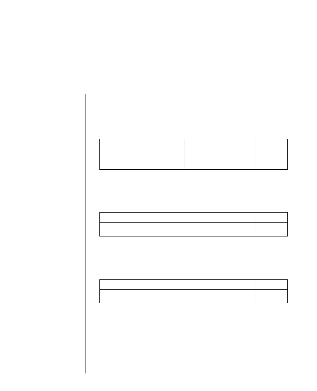
Character Format
Double Width
One Line Printing ASCII Hexadecimal Decimal
Sets double width one line SO 0E 14
Cancels double wide one line DC4 14 20
Double character width for one line only; prints half as many
characters per inch in each pitch. SO can also be cancelled by a
carriage return, line feed, VT, or Form Feed or ESC W 0 command.
At the end of the line of double wide characters, current print
mode resumes. ESC W 1 takes precedence over SO.
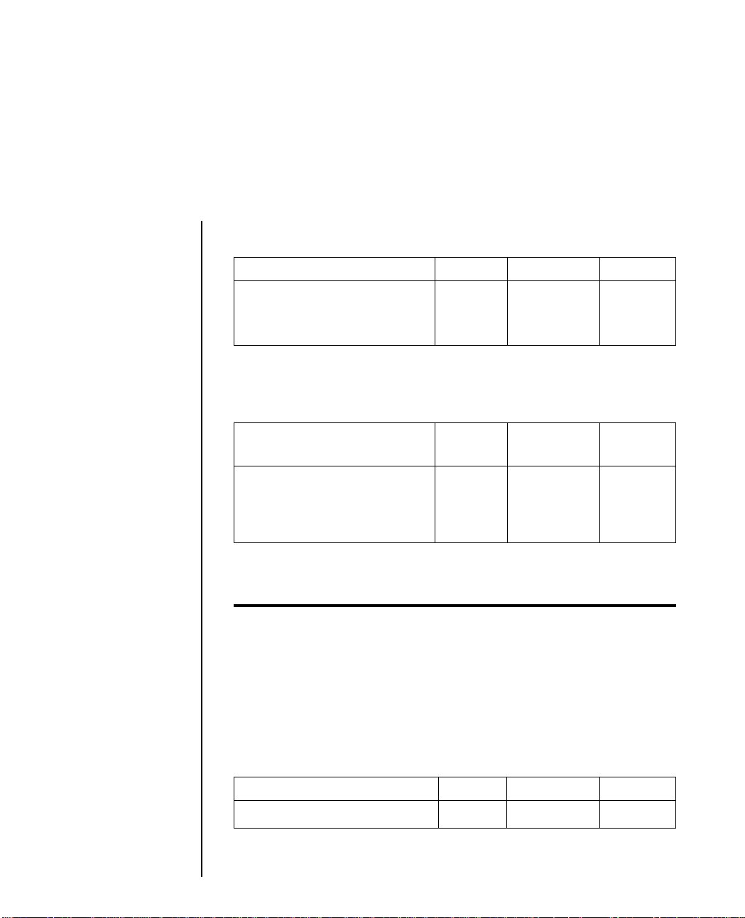
Continuous Double
Width Printing ASCII Hexadecimal Decimal
Sets double width print mode ESC W 1 1B 57 31 27 87 49
Cancels double width ESC W 0 1B 57 30 27 87 48
print mode
Doubles the width of all characters; produces half as many
characters per inch in each pitch. With this command, double
width characters print continuously until reset by ESC W 0.
Double width can also be set by the ESC [ @ command. The DC4
commandcancel double width one line will not cancel the
double width mode set by ESC W 1.
IBM Control Code Reference 3 1
Page 60

Triple Width Printing ASCII Hexadecimal Decimal
Sets triple width printing ESC m 1B 6D 27 109
Cancels triple width printing ESC W 0 1B 57 30 27 87 48
Triples the width of the characters. You can also cancel this feature
by choosing either double or single width printing in the Menu
Select mode.
Double/Triple Height ASCII Hexadecimal Decimal
Sets double height printing ESC US LB LF 01 27 3l 1
SOH
Sets triple height printing ESC US LB LF 02 27 31 2
STX
Cancel double/triple height ESC US LB LF 00 27 31 0
NUL
Double/triple height characters are printed twice/three times the
height of standard characters from the same base line. Double/
triple and standard height characters can all be printed within the
same line. To avoid having lines overlap, use the variable line
spacing command to set double line spacing for double height and
triple line spacing for triple height. You may also set it through
your software. Print modes that accommodate double/triple height
include utility and DLL utility, emphasized, double/triple width,
and NLQ/LQ. Two and three passes are required for double and
triple height characters respectively.
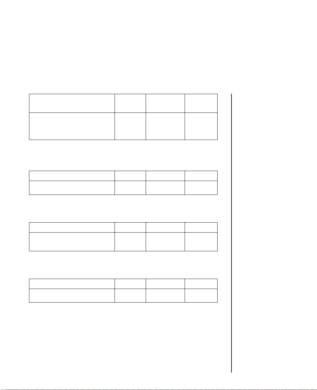
Double Width/
Double Height ASCII Hexadecimal Decimal
Set double width or ESC [ @ n1 1B 5B 40 n1 27 91 64
double height printing n2 m1 m2 n2 m1 m2 n1 n2 m1
m3 m4 m3 m4 m2 m3 m4
3 2 IBM Control Code Reference
Page 61

With this command you can set either double height or double
width or both, together with the control of line spacing. The
following table will help you choose the correct parameters for
your requirements.
n1 and n2 are the number of bytes in the sequence. Normally this
will be four so n1 = 4 and n2 = 0.
m1 to m4 are the modes available. m1 and m2 are ignored and are
therefore constantly set at 0. m3 defines the character height and
line feed value. m4 defines character width.
CHR$ (m3) Function
0 No change
1 LF unchanged/standard height characters
2 LF unchanged/double height characters
16 single LF/character height unchanged
17 single LF/standard height characters
18 single LF/double height characters
32 double LF/character height unchanged
33 double LF/standard characters
34 double LF/double height characters
CHR$(m4) specifies either standard or double width characters as
follows.
CHR$ (m4) Function
0 no change
1 standard
2 double width characters
IBM Control Code Reference 3 3
Page 62

Italic Characters ASCII Hexadecimal Decimal
Sets italic print mode ESC % G 1B 25 47 27 37 71
Cancels italic printing ESC % H 1B 25 48 27 37 72
Prints italic (slanted) characters. You can also select italic printing
using the menu. Characters may overlap on to the next character
cell. IBM line graphics (position 176-223) and the integral sign
halves (position 244 and 245) will not be slanted.
Select IBM Character Set ASCII Hexadecimal Decimal
Select IBM Set 1 ESC 7 1B 37 27 55
Select IBM Set 2 ESC 6 1B 36 27 54
Use these commands to select either of the IBM character sets
illustrated in Appendix B.
Print from All Character Set ASCII Hexadecimal Decimal
Print one character ESC ^ n 1B 5E n 27 94 n
Print continuously ESC \ n1 1B 5C n1 n2 27 95 n1
n2 n2
Using these commands you can make control characters like ESC
or SI printable. Using the All Character Set there is a printable
character for all 255 places of the character table. If you want to
print just one character from this set use ESC ^ n, where n specifies
this character. If you want to print m characters, use ESC \ n1 n2.
Take the following formula to specify n1 and n2:
m = n1 = (n2 * 256)
The m control codes or characters to be printed must follow
ESC\ n1 n2. You will find the All Character tables in Appendix B.
3 4 IBM Control Code Reference
Page 63

Emphasized Printing ASCII Hexadecimal Decimal
Sets emphasized print mode ESC E 1B 45 27 69
Cancels emphasized print mode ESC F 1B 46 27 70
Prints second dot slightly to the right of each printed dot, creating
characters that are thicker horizontally. Emphasized printing is
performed at half-speed, and can be done in conjunction with
enhanced printing. The Menu Select mode can also implement
emphasized printing.
Enhanced/Double
Strike Printing ASCII Hexadecimal Decimal
Sets enhanced print mode ESC G 1B 47 27 71
Cancels enhanced print mode ESC H 1B 48 27 72
Prints second dot slightly below each printed dot, creating
characters that are thicker vertically. The printer makes two passes
per line. This feature can be combined with emphasized printing.
The Menu Select mode can also control enhanced printing.
Character Pitch ASCII Hexadecimal Decimal
10 CPI DC2 12 18
12 CPI ESC : 1B 3A 27 58
15 CPI ESC g 1B 67 27 103
17.1 CPI SI 0F 15
20 CPI ESC SI 1B 0F 27 15
You can directly get to 12 CPI from 10 CPI by using ESC :. In order
to use 17.1 CPI character pitch you must use the SI control code
when you are in 10 CPI mode.
IBM Control Code Reference 3 5
Page 64

Proportional Spacing ASCII Hexadecimal Decimal
Sets/cancels proportional spacing ESC P n 1B 50 n 27 80 n
Either sets or cancels proportional printing. Where n=1 proportional
printing is turned on; where n=0 it is turned off. Proportional
spacing is only available in LQ mode.
Superscript Printing ASCII Hexadecimal Decimal
Sets superscript mode ESC S 0 1B 53 30 27 83 48
Cancels superscript mode ESC T 1B 54 27 84
Superscripts cannot be printed in double or triple height, but the
superscript command is not cancelled by double or triple height
commands. You can print superscripts in compressed print mode;
they appear as half-high, full-width characters.
Subscript Printing ASCII Hexadecimal Decimal
Sets subscript mode ESC S 1 1B 53 31 27 83 49
Cancels subscript mode ESC T 1B 54 27 84
Subscripts cannot be printed in double or triple height, but the
subscript command is not cancelled by double or triple height
commands. You can print subscripts in compressed print mode;
they appear as half-height, full-width characters.
3 6 IBM Control Code Reference
Page 65
Select Font ASCII Hexadecimal Decimal
Select Font ESC [ I n1 1B 5B 49 n1 27 91 73
n2 m1 m2 n2 m1 m2 p1 n1 n2 m1
p1 p2 r1 p2 r1 m2 p1 p2
r1
n1 n2: Number of parameters n1 + 256 * n2
m1 m2: Font ID number 256 * m1 + m2
p1 p2: Font width 256 * p1 + p2
r1: Spacing
n1 and n2 are the number of bytes in the sequence. Normally this
will be five so n1 =5 and n2 =0. m1 and m2 define the Font ID
number of the font to be selected. See table below.
Typeface m1 m2 Typeface m1 m2
Courier 000 008 Roman 000 155
000 011 000 159
000 018 000 166
000 049 000 167
000 085
000 092 Letter Gothic 000 087
000 098 000 222
000 171 000 255
000 223
000 226 Script 000 084
Prestige Elite 000 012 OCR-B 000 003
000 080
000 086 OCR-A 000 019
000 100
000 164 ORATOR 000 005
000 221
p1 and p2 define the font width in units of 1/1440".
IBM Control Code Reference 3 7
Page 66

For example:
To set 10 CPI, p1 =0 and p2 = 144
See table below
p1 p2 Description
000 000 No Change
000 072 20 pitch
000 084 17 pitch
000 096 15 pitch
000 120 12 pitch
000 144 10 pitch
If p1 = 0 and p2 = 0, there is no change.
r1 defines the font spacing.
If r 1 = 0, no change.
If r 1 = 1, fixed pitch defined by p1 and p2 is available.
If r 1 = 2, proportional spacing is defined.
Font Selection ASCII Hexadecimal Decimal
Selects typestyles ESC k n 1B 6B n 27 107 n
With this command you can choose either the typestyles resident
in the printer or a typestyle in an optional font cartridge. If the
value of n is not one of those given in the table below, the resident
typestyle will be selected.
3 8 IBM Control Code Reference
Page 67

.
Decimal value of n Typestyle
0 Roman
1 Swiss
2 Courier (default font)
3 Prestige
5 OCR-B (with OCR-B font cartridge
installed)
6 OCR-A (with OCR-A font cartridge
installed)
122 Swiss Bold
124 Letter Gothic
126 Resident
127 Cartridge (with any font cartridge installed)
IBM Control Code Reference 3 9
Page 68

Page Format
Margin Setting ASCII Hexadecimal Decimal
Left/right margin set ESC X 1B 58 n1 n2 27 82 n1
n1 n2 n2
The CHR$(27);X;CHR$(n1);CHRS(n2); command sets the left
and the right margins at the same time. In this command, n1
represents the left margin and n2 represents the right one. Both n1
and n2 refer to the character column 0.
The following table gives you the maximum values for n1 and n2.
If n1 or n2 are 0 the current margin value will be used for n1 and
n2.
Character Pitch 10 CPI 12 CPI 15 CPI 17.1 CPI 20 CPI PROP
Max. column 136 163 204 233 272 163
n2-n1 min. 3 4 5 6 6 4
Auto Skip Over Perforation ASCII Hexadecimal Decimal
Set skip over perforation ESC N n 1B 4E n 27 78 n
Cancels skip over perforation ESC O 1B 4F 27 79
Sets the printer to automatically skip a specified number of lines
between the last printed line of one page and the first printed line
on the next page. The allowable range that can be skipped may be
set from 1 to 255 lines at the current line spacing; the value of n
cannot exceed the length of the current form. ESC N is reset by the
ESC O command or a page length set command.
3 10 IBM Control Code Reference
Page 69
This feature is handy for printing program listings, and printouts
from software that has no format control. However, we advise
against using it with packages that do have page formatting
controls, such as word processors: the skip over perforation is
likely to interfere with the software and ruin your page format.
Form Length in Inches ASCII Hexadecimal Decimal
Sets form length in inches ESC C 1B 43 00 n 27 67 0 n
NUL n
Sets the form length to a specific number of inches where the value
of n ranges from 1 to 182. The top of form position is set by this
command, vertical tab settings are cleared, and the skip over
perforation is cleared.
Form Length by Lines ASCII Hexadecimal Decimal
Sets form length by lines ESC C n 1B 43 n 27 67 n
Sets the form length to a specific number of lines where the value
of n ranges from 1 to 255. This command also sets the top of form
position, clears vertical tab settings, and resets the skip over
perforation.
Top of Form Set ASCII Hexadecimal Decimal
Sets TOF ESC 4 1B 34 27 52
The current position of the printhead will become the new top of
form position (TOF) upon the receipt of this command. This
command only sets the TOF when continuous form paper is
installed in the printer and is ignored in CSF and SASF modes.
IBM Control Code Reference 3 11
Page 70

Vertical Margins Setting ASCII Hexadecimal Decimal
Vertical Margins Setting ESC [ S 1B 5B 53 n1 27 91 83
n1 n2 m1 n2 m1 m2 n1 n2
m2 p1 p2 p1 p2 m1 m2
p1 p2
n1 n2: number of parameters n1 + 256 * n2
m1 m2: top margin 256 * m1 + m2
p1 p2: bottom margin 256 * p1 + p2
n 1 and n2 are the number of bytes in the sequence. Normally this
will be four so n1 = 4 and n2 = 0 or two n1 = 2 and n2 = 0.
m1 and m2 defines the top margin distance from the top of form
to the edge of the first line. The unit is 1/1440".
p1 and p2 defines the bottom margin distance from the top of form
to the top edge of the bottom margin.
The unit is 1/1440".
3 12 IBM Control Code Reference
Page 71
Line spaclng
Lines Per Inch Spacing ASCII Hexadecimal Decimal
Sets line spacing to 1/8 inch ESC 0 1B 30 27 48
(8 lines per inch)
Sets line spacing to 7/72 inch ESC 1 1B 31 27 49
Sets line spacing to 1/8 or 7/72 inch. These commands do not
affect the top of form position. You can also set 8 lines per inch in
the Menu Select mode.
Variable n/72 inch
Line Spacing ASCII Hexadecimal Decimal
Selects line spacing value as ESC A n 1B 41 n 27 65 n
n/72 inch*
Activates the line spacing ESC 2 1B 32 27 50
selected by ESC A n*
ESC A n stores line spacing value in n/72 inch where n can
range from 1 to 85.
Important: Values greater than 85 may result in uncontrolled printing.
This line spacing must be activated by ESC 2 to come into effect.
For example, to set line spacing for double height characters, n
would be 24. Then to set line spacing for triple height characters,
n would be 36.
Using the ESC 2 sequence without a previous ESC A n sets the line
spacing to 6 lines per inch.
Fine Line Spacing ASCII Hexadecimal Decimal
Sets the line spacing to n/216 inch* ESC 3 n 1B 33 n
27 51 n
Sets line spacing to n/216 of an inch where n can range from 1 to
IBM Control Code Reference 3 13
Page 72
255.
Sets Base Unit to 1/180 inch
or 1/216 inch ASCII Hexadecimal Decimal
Sets base unit for ESC 3 ESC \ 4 0 1B 5B 5C 04 27 91 92 4
and ESC J to 1/180 inch or 0 0 n1 n2 00 00 00 0 0 0
1/216 inch n1 n2 n1 n2
This command sets the base unit used in the commands ESC 3 and
ESC J to either 1/180 inch or 1/216 inch. n1 = either 180 or 216,
n2 = 0.
Line feed ASCII Hexadecimal Decimal
Executes line feed LF 0A 10
Depending on the setting of the AUTO CR item in the menu a CR
will be added or not.
Auto Line Feed ASCII Hexadecimal Decimal
Sets Auto LF on ESC 5 1 1B 35 31 27 53 49
Sets Auto LF off ESC 5 0 1B 35 30 27 53 48
When Auto-LF is set to ON, each CR will cause a line feed to be
executed.
Fine Line Feed (n/216 inch) ASCII Hexadecimal Decimal
Executes n/216 inch line feed* ESC J n 1B 4A n 27 74 n
ESC J n sends an immediate n/216 inch line feed without changing
the current line spacing. The variable n can have a range of 1 to 255.
This command will not clear one-line double width character code
SO. The menu setting defines whether a CR is sent.
3 14 IBM Control Code Reference
Page 73
Reverse Line Feed ASCII Hexadecimal Decimal
Executes reverse line feed ESC ] 1B 5D 27 93
The current horizontal position does not change when this
command is executed.
* These commands have different functions in AGM. (Refer to the IBM
Alternative Graphics Mode in Chapter 3).
Note: Depending on the language set selected by menu, ] could be another
character.
IBM Control Code Reference 3 15
Page 74

Printing Features
Underlining ASCII Hexadecimal Decimal
Sets underline mode ESC - 1 1B 2D 31 27 45 49
Cancels underline mode ESC - 0 1B 2D 30 27 45 48
Underlining occurs at the same time characters are printed. The
underline for super-/subscript characters appears on the same
print line as that of the preceding characters, but does not strike
through subscripts. All text, including spaces and punctuation, is
underlined. Graphics are not underlined.
Overscoring ASCII Hexadecimal Decimal
Sets overscore mode ESC _ 1 1B 5F 31 27 95 49
Cancels overscore mode ESC _ 0 1B 5F 30 27 95 48
Overscoring prints a continuous line over the characters designated.
The overscore for super-/subscript appears on the same line as for
the preceding character.
Print Mode Composite ASCII Hexadecimal Decimal
Selects print mode ESC I n 1B 49 n 27 73 n
3 16 IBM Control Code Reference
Page 75

n Dec Print Mode Character Pitch
0 Utility 10 CPI
2 LQ 10 CPI
3 LQ Proportional
4 Utility DLL 10 CPI
6 LQ DLL 10CPI
7 LQ DLL Proportional
8 Utility 12 CPI
10 LQ 12 CPI
12 Utility DLL 12 CPI
14 LQ DLL 12 CPI
16 Utility 17.1 CPI
18 LQ 17.1 CPI
20 Utility DLL 17.1 CPI
22 LQ DLL 17.1 CPI
24 Utility 15 CPI
26 LQ 15 CPI
32 Utility 20 CPI
34 LQ 20 CPI
Using this composite command you can specify the print mode
and the character pitch within one command.
LQ stands for Letter Quality and DLL for DownLine Loadable
characters.
NLQ/High Speed Draft ASCII Hexadecimal Decimal
Sets NLQ printing ESC # 2 or 1B 23 32 or 27 35 50
or
ESC ( 2 1B 28 32 27 40 50
Sets High Speed Draft ESC # 0 or 1B 23 30 or 27 35 48
or
ESC ( 0 1B 28 30 27 40 48
NLQ prints in either 10 or 12 CPI, while the High Speed Draft
mode functions in either 15 or 18 CPI. Before switching print
modes, make sure that the printer is set for a compatible pitch.
IBM Control Code Reference 3 17
Page 76

Colour Printing ASCII Hexadecimal Decimal
Selects Colour Printing ESC r n 1B 72 n 27 114 n
Colour printing is available on the ML393C printer only. If you
own an ML393C, you must have a colour ribbon installed in order
to print colour. You must also change the menu setting from
BLACK RIBBON to another selection. We recommend BLACK
which is the black band of the colour ribbon. Using this selection,
black is selected as the standard colour but all other colours are
also available to you through software commands.
Use the ESC r n command to print in colour. Your selection for n
represents a particular colour as depicted in the following table.
Value of n Colour
0 Black
1 Magenta
2 Cyan
3 Violet
4 Yellow
5 Orange
6 Green
National Character Set ASCII Hexadecimal Decimal
Selects National Character Set ESC ! n 1B 21 n 27 33 n
Selects from 19 character sets a specific international character set,
each of which has a set of characters and symbols used in a
particular language. The decimal value of n ranges from 64 to 81
and 90. The following table shows the values that access these
character sets.
3 18 IBM Control Code Reference
Page 77

Language n ASCII n decimal n Hexadecimal
USA (0) @ 64 40
USA (0) A 65 41
British B 66 42
German C 67 43
French D 68 44
Swedish 1 E 69 45
Danish F 70 46
Norwegian G 71 47
Dutch H 72 48
Italian I 73 49
French-Canadian J 74 4A
Spanish K 75 4B
Swedish 2 L 76 4C
Swedish 3 M 77 4D
Swedish 4 N 78 4E
Turkish O 79 4F
Swiss 1 P 80 50
Swiss 2 Q 81 51
Legal/Publisher Z 90 5A
IBM Control Code Reference 3 19
Page 78

Code Page
Normally the code page USA is the base for printable characters
for the IBM Character Sets 1 and 2 and the All Character Set. In the
sets 1 and 2 some areas are used for control codes, in the All
Character Set all 255 positions are printable.
These printable characters are reassigned using the code pages,
the control codes in the IBM sets 1 and 2 do not change.
To use one of the Code Pages the menu must be set accordingly.
Using code pages like Multilingual, Norway, Turkey or Portugal
enables you to use national characters and symbols which are not
available in the normal character sets. The Code Page Character
Sets are shown in Appendix B.
National characters ASCII Hexadecimal Decimal
Select Code Page ESC [ T 1B 5B 54 27 91 84
ENQ NUL 05 00 00 00 5 0 0 0
NUL NUL n1 n2 00 n1 n2 0
n 1 n2 NUL
These commands allow you to select character sets that replace
some less frequently used characters with symbols used in a
variety of European languages.
Note: When Code Pages are selected, slashed zero can be selected by the menu.
To select code pages in IBM emulation, take the IBM ID number
and divide it by 256. Assign this number to n1 and the remainder
to n2.
Example To specify code page 850 use this BASIC statement:
LPRINT CHR$ (27); [T; CHR$ (5); CHR$ (0); CHR$ (0);
CHR$ (0);CHR$ (3); CHR$ (82); CHR$ (0);
3 20 IBM Control Code Reference
Page 79

Carriage Movement
Backspace ASCII Hexadecimal Decimal
Backspace BS 08 8
This prints data that is in the print buffer and moves the printhead
one character to the left. The actual width of the backspace
depends on the pitch in effect.
Horizontal Tab ASCII Hexadecimal Decimal
Execute horizontal tab HT 09 9
Causes the printhead to skip to the next horizontal tab setting
which is specified either through default or the ESC D command.
Tab positions are pitch dependent; settings remain in effect with
pitch change.
Vertical Tab ASCII Hexadecimal Decimal
Tabs to next stop VT 0B 11
Prints data in the print buffer and advances paper to the next stop
programmed by ESC B. If the AUTO CR option in the menu is set
to YES a CR will be added to each VT. If no vertical tabs have been
set, the VT command will be executed as a Line Feed.
Form Feed ASCII Hexadecimal Decimal
Advances to TOF FF 0C 12
Advances paper to the next top of form according to the current
page length. A CR will be executed automatically.
IBM Control Code Reference 3 21
Page 80
Carriage Return ASCII Hexadecimal Decimal
Carriage Return CR 0D 13
Initiates the printing of data from the print buffer and resets oneline double width mode. If the Auto Line Feed is set, a line feed is
also automatically executed with the CR command.
Horizontal Tab ASCII Hexadecimal Decimal
Set Horizontal Tab ESC D n1 1B 44 n1 27 68 n1
n2 n3... n2 n3 ...00 n2 n3 ...0
NUL
Sets up to 28 horizontal tabs, which depend on the character pitch
in effect. Specify tab settings from the home position in ascending
order, and end the sequence with NUL. The range of n is a decimal
value from 1 to 255. Tab settings are absolute and change in
accordance with the left margin if it is reset.
The HT command then causes the printer to skip to the next
horizontal tab.
Maximum n values are specified in the following table according
to pitch:
Pitch Max. Value
10 135
12 162
15 203
17.1 232
18 243
20 255
ESC D NUL deletes all horizontal tabs.
3 22 IBM Control Code Reference
Page 81

Vertical Tabs ASCII Hexadecimal Decimal
Sets Vertical Tab stops ESC B n1 1B 42 n1 27 66 n1
n2 NUL n2...00 n2...0
Sets from 1 to 64 absolute vertical tabs where n represents the line
number, ranging from 1 to 255. Values must be entered in ascending
order. Tabs are set in the current line spacing. End the tab sequence
with NUL.
The VT command then causes the printer to skip to the next tab
stop.
Vertical tabs are cleared with ESC B NUL or ESC R.
Default Tab Setting ASCII Hexadecimal Decimal
Sets Tabs to default ESC R 1B 52 27 82
The horizontal tabs will be set to their default value, which is every
8th column starting at column 9. The vertical tabulators will all be
cleared, so a VT will result in a LF.
Relative Dot Position ASCII Hexadecimal Decimal
Relative dot position n/120 inch ESC d n1 n2 1B 64 nl n2 27 100 nl n2
Moves the print position a specified number of n/120 inches (dots)
to the right of the current position. To calculate the values of nl and
n2, divide the number of dots (n) you want to move by 256; the
result is n2 and the remainder is n1.
In other words, n = n1 + n2*256. The dot position is not print mode
dependant. Values beyond the right margin will jump to the right
margin.
IBM Control Code Reference 3 23
Page 82

Space Backwards ASCII Hexadecimal Decimal
Space Backwards ESC e n1 1B 65 n1 n2 27 101 n1
n2 n2
This moves the print position a specified number of n/l 20 inches
to the left of the current position.
To calculate the values of n1 and n2, divide the number of dots (n)
you want to move by 256; the result is n2 and the remainder is n1.
n = n1 + n2 * 256.
Values beyond the left margin moves the cursor to the left margin.
3 24 IBM Control Code Reference
Page 83
Utility Commands
Print Suppress Mode ASCII Hexadecimal Decimal
Sets print suppress ESC Q # 1B 51 23 27 81 35
Cancels print suppress DC1 11 17
When it receives the ESC Q # command, the printer ignores all
data until it receives the DC1 command. The SELECT light will
blink when the printer is in Print Suppress mode. The PRINT
SUPPRESS EFFECTIVE menu option must be set to VALID for
these commands to be activated.
Deselect Printer ASCII Hexadecimal Decimal
Sets printer offline ESC j 1B 6A 27 106
This command changes the printer from the select to the deselect
mode like pushing the SELECT button. The only way to get into
select mode again is to push the SELECT button.
Cancel ASCII Hexadecimal Decimal
Clears data CAN 18 24
Clears the print buffer. This command does not affect control
codes stored in the printers memory.
Unidirectional Printing ASCII Hexadecimal Decimal
Unidirectional printing on ESC U 1 1B 55 31 27 85 49
Unidirectional printing off ESC U 0 1B 55 30 27 85 48
IBM Control Code Reference 3 25
Page 84
Your printer is designed to maximize speed by printing alternately
from the left and the right, rather than moving the printhead back
to the left margin for each line. This bidirectional printing is fast,
but may result in vertical misalignment of graphics or double and
triple height characters.
Turn on unidirectional printing when precise vertical alignment
from line to line is critical.
Quiet Mode ASCII Hexadecimal Decimal
Set quiet print mode ESC q 1 1B 71 31 27 113 49
Cancel quiet mode ESC q 0 1B 71 30 27 113 48
Quiet mode reduces noise while the printer is in LQ, utility, or
graphics modes. You can also select quiet mode on the front panel.
You will notice that printing is much slower when you turn on
quiet mode.
Paper Out Detector ASCII Hexadecimal Decimal
Enables paper out detector ESC 9 1B 39 27 57
Disables paper out detector ESC 8 1B 38 27 56
The detector senses when less than one inch of paper remains.
When this happens, the alarm light goes on and the printer is
deselected. This command overrides the detector so that you can
print closer to the bottom of the page. (The feature is also menu
selectable.) You can also override the detector manually by pressing
the SELECT button, which causes the printing of a line of data
followed by a line feed. Unprinted data is saved and printed after
paper is replaced.
Bell/Buzzer ASCII Hexadecimal Decimal
Sounds buzzer BEL 07 7
This command sounds a beeper in the printer.
3 26 IBM Control Code Reference
Page 85

Cut-Sheet Feeder Control
These commands are only valid when a cut sheet feeder is installed.
CSF Single Paper Feed ASCII Hexadecimal Decimal
Feeds paper ESC EM I 1B 19 49 27 25 73
This command feeds a sheet of paper to the top of form position.
If paper is already loaded, the printer ejects the loaded paper, and
loads another sheet. The FF code is used to feed paper from the
output tray.
CSF Single Sheet Eject ASCII Hexadecimal Decimal
Eject single sheet ESC EM R 1B 19 52 27 25 82
Ejects a single sheet. Data in the print buffer is printed before paper
is ejected. A line feed code at the end of the page causes next sheet
to load automatically.
Multi Bin Select ASCII Hexadecimal Decimal
Determines paper bin ESC EM n 1B 19 n 27 25 n
Determines which paper bin is active when the dual bin CSF 3002
is installed. Bin 1 is the default. Replace n with 2 to select bin 2, or
1 to select bin 1.
Note: Use Bin 1 for envelopes and be sure to adjust the printhead gap. See the
Setup Guide for details.
IBM Control Code Reference 3 27
Page 86
Cut Sheet Feeder ASCII Hexadecimal Decimal
Cut Sheet Feeding ESC [ F 1B 5B 46 27 91 70
n1 n2 n1 n2 n1 n2
m1 m2 m3 m1 m2 m3 m1 m2 m3
n1 n2: number of parameters n1 + n2 * 256
m1: paper feeding method
m2: reserved should be m2 = 1 or m2 = 3
m3: bin number
n1 and n2 are the number of bytes in the sequence. Normally this
will be three so n1 = 3 and n2 = 0.
m1 defines paper feeding method and m2 is usually set to 1 and m3
defines the bin number.
m1 = 1 set manually inserting mode
m1 = 3 set CSF mode
m3 = 0 no change
m3 = 1 Bin 1
m3 = 2 Bin 2
3 28 IBM Control Code Reference
Page 87
Chapter 4
EPSON Control Code Reference
Character Format
Character Format (One line) ASCII Hexadecimal Decimal
Sets double width for one line SO or 0E or 14 or
ESC SO 1B 0E 27 14
Cancels double width for one line DC4 14 20
Doubles character width for one line only; prints half as many
characters per inch in each pitch. SO and ESC SO can also be
cancelled by a carriage return or line feed, ESC W 0 or the ESC !
command. At the end of the line of double width characters
current print mode resumes. ESC W 1 takes precedence over SO.
Continuous Double
Width Printing ASCII Hexadecimal Decimal
Sets double width print mode ESC W 1 1B 57 31 or 27 87 49
or FS E 1 1C 45 31 or 28 69 49
Cancels double width print ESC W 0 1B 57 30 or 27 87 48
or FS E 0 1C 45 30 or 28 69 48
Doubles the width of all characters; produces half as many
characters per inch in each pitch. With this command, double
width characters print continuously until reset by ESC W 0.
Double width can also be set by the ESC ! command.
Triple Width Printing ASCII Hexadecimal Decimal
Sets triple width printing ESC m 1B 6D 27 109
Cancels triple width printing ESC W 0 1B 57 30 27 87 48
Triples the width of the characters. You can also cancel this feature
by choosing either double or single width printing in the Menu
Select mode.
EPSON Control Code Reference 4 1
Page 88
Double/Triple Height ASCII Hexadecimal Decimal
Sets double height printing ESC US SOH 1B 1F 01 27 31 1
Sets triple height printing ESC US STX 1B 1F 02 27 31 2
Cancel double/triple height ESC US NUL 1B 1F 00 27 31 0
Sets double height printing FS V SOH 1C 56 01 28 86 1
Cancel double height printingFS V NUL 1C 56 00 28 86 0
Sets triple height printing ESC w SOH 1B 77 01 27 119 1
Cancel triple height printing ESC w NUL 1B 77 00 27 119 0
Double/triple height characters are printed twice/three times the
height of standard characters from the same base line. Double/
triple and standard height characters can all be printed within the
same line. To avoid having lines overlap, use the variable line
spacing command to set double line spacing for double height and
triple line spacing for triple height. You may also set it through
your software. Print modes that accommodate double/triple height
include utility and DLL utility, emphasised, double/triple width,
and NLQ/LQ. Two and three passes are required for double and
triple height characters respectively.
Italic Characters ASCII Hexadecimal Decimal
Set italic print mode ESC 4 1B 34 27 52
Cancels italic printing ESC 5 1B 35 27 53
Prints italic (slanted) characters. You can also select italic printing
using the ESC ! command or the menu. Characters may overlap on
to the next character cell.
4 2 EPSON Control Code Reference
Page 89

Select IBM Character Set ASCII Hexadecimal Decimal
Selects IBM Set 1 ESC 7 1B 37 27 55
Selects IBM Set 2 ESC 6 1B 36 27 54
Use these commands to select either of the IBM character sets
illustrated in Appendix B. Before selecting either set, send the
command ESC t 1 to select the graphics character tables.
Compressed Print ASCII Hexadecimal Decimal
Sets 17.1 or 20 CPI pitch SI or 0F or 15 or
ESC SI 1B 0F 27 15
Cancels 17.1/20 CPI DC2 12 18
When compressed print is in effect, pica print (10 cpi) becomes 17.1
cpi, and elite print (12 cpi) becomes 20 cpi. Neither double nor
triple width is affected by the SI command, which you can place
anywhere within a line.
Emphasised Printing ASCII Hexadecimal Decimal
Sets emphasised print mode ESC E 1B 45 27 69
Cancels emphasised print mode ESC F 1B 46 27 70
Prints second dot slightly to the right of each previously printed
dot, creating characters that are thicker horizontally. Emphasised
printing is performed at half speed, and can be done in conjunction
with enhanced printing. The ESC ! command and the Menu Select
mode can also implement emphasised printing.
Enhanced/Double Strike
Printing ASCII Hexadecimal Decimal
Sets enhanced print mode ESC G 1B 47 27 71
Cancels enhanced print mode ESC H 1B 48 27 72
EPSON Control Code Reference 4 3
Page 90

Prints second dot slightly below each printed dot, creating
characters that are thicker vertically. The printer makes two passes
per line. This feature can be combined with emphasised printing.
ESC ! command and the Menu Select mode can also control
enhanced printing.
Outline and Shadow Printing ASCII Hexadecimal Decimal
Begin outline ESC q 1B 71 01 27 113 1
SOH
Begin shadow ESC q 1B 71 02 27 113 2
STX
Begin shadow and outline ESC q 1B 71 03 27 113 3
ETX
End shadow and/or outline ESC q 1B 71 00 27 113 0
NUL
Use the outline and shadow effects to produce more interesting
and stylish headings. They can be combined together, as well as
with emphasized and/or enhanced printing for an even more
striking effect.
Note: Outline and shadow printing commands can only be used for printing
characters, they cannot be used to print line graphics.
Character Pitch ASCII Hexadecimal Decimal
Elite (12 cpi) ESC M 1B 4D 27 77
Pica (10 cpi) ESC P 1B 50 27 80
15 CPI ESC g 1B 67 27 103
In compressed mode, elite pitch becomes 20 cpi and pica becomes
17.1 cpi; compressed mode does not affect 15 cpi.
Note: You can make pitch changes within a line without affecting double or triple
width printing.
4 4 EPSON Control Code Reference
Page 91

Space Between Characters ASCII Hexadecimal Decimal
Sets spacing between characters ESC SP n 1B 20 n 27 32 n
Upon receipt of this command the printer determines the amount
of space to be added to the right of each character which is to be
specified in dots. The value of n may be from 0 to 127.
Proportional Spacing ASCII Hexadecimal Decimal
Sets/cancels proportional spacing ESC p n 1B 70 n 27 112 n
Either sets or cancels proportional printing. Where n = l
proportional printing is turned on; where n = 0 it is turned off.
Superscript Printing ASCII Hexadecimal Decimal
Sets superscript mode ESC S 0 1B 53 30 27 83 48
Cancels superscript mode ESC T 1B 54 27 84
You can print superscripts in the compressed print mode; they
appear as half height, full-width characters.
Subscript Printing ASCII Hexadecimal Decimal
Sets subscript mode ESC S 1 1B 53 31 27 83 49
Cancels subscript mode ESC T 1B 54 27 84
You can print subscripts in the compressed print mode; they
appear as half-height, full-width characters.
EPSON Control Code Reference 4 5
Page 92

Font Selection ASCII Hexadecimal Decimal
Select typestyles ESC k n 1B 6B n 27 107 n
With this command, you can choose either the typestyle resident
in the printer or a typestyle in an optional font cartridge. If the
value of n is not one of those given in the following table, the
resident typestyle will be selected.
Decimal value of n Typestyle
0 Roman
1 Swiss
2 Courier (default font)
3 Prestige
5 OCR-B (with OCR-B font cartridge
installed)
6 OCR-A (with OCR-A font cartridge
installed)
122 Swiss Bold
124 Letter Gothic
126 Resident (Courier)
127 Cartridge (with any font cartridge
installed)
Extended Character Set ASCII Hexadecimal Decimal
Italics set ESC t NUL or 1B 74 00 or 27 116 0
FS I NUL 1C 49 00 28 73 0
Graphics set ESC t SOH or 1B 74 01 or 27 116 1 or
FS I SOH 1C 49 01 28 73 1
DLL Set ESC t STX 1B 74 02 27 116 2
This command selects the set of characters printed for the high
ASCII values, 128 through 255. Use the command ESC t 1 before
selecting one of these graphics character sets.
4 6 EPSON Control Code Reference
Page 93

Page Format
Left Margin ASCII Hexadecimal Decimal
Sets left margin ESC l n 1B 6C n 27 108 n
This command sets the left margin. The value of n is the width of
the margin from the far left printhead position, measured in
spaces at the active character pitch (proportional spacing is treated
as 10 cpi). Changing the pitch later will not affect the margin.
Send this command at the beginning of a line, because it will delete
any data that has been sent to the printer, but has not been printed.
Using this command will reset horizontal tabs to the default of
eight spaces, starting at the new margin.
The left margin cannot be more than 254 spaces, and it must be less
than the right margin. The following table shows the maximum
allowable left and right margins for the various character pitches.
Pitch (cpi) Left Margin Right Margin
10 135 136
12 162 163
15 203 204
17.1 232 233
18 243 244
20 254 255
EPSON Control Code Reference 4 7
Page 94

Right Margin ASCII Hexadecimal Decimal
Sets right margin ESC Q n 1B 51 n 27 81 n
This command sets the right margin. The value of n is the margins
distance from the far left printhead position, measured in spaces
at the active character pitch. (Proportional spacing is treated as 10
cpi). Changing the pitch later will not affect the margin.
Send this command at the beginning of a line, because it will delete
any data that has been sent to the printer, but has not been printed.
The right margin cannot be more than 255 spaces, and it must be
greater than the left margin. The previous table shows the maximum
allowable left and right margins for the various character pitches.
Auto Skip Over Perforation ASCII Hexadecimal Decimal
Sets skip over perforation ESC N n 1B 4E n 27 78 n
Cancels skip over perforation ESC O 1B 4F 27 79
Sets the printer to automatically skip a specified number of lines
between the last printed line of one page, and the first printed line
on the next page. The allowable range that can be skipped may be
set from 1 to 127 lines at the current line spacing; the value of n
cannot exceed the length of the current form. ESC N is reset by the
ESC O command or a page length set command.
This feature is handy for printing program listings, and printouts
from software that has no format control. However, we advise
against using it with packages that do have page formatting
controls, such as word processors: the skip over perforation is
likely to interfere with the software and ruin your page format.
4 8 EPSON Control Code Reference
Page 95

Form Length in inches ASCII Hexadecimal Decimal
Sets form length in inches ESC C 1B 43 00 n 27 67 0 n
NUL n
Sets the form length to a specific number of inches where the value
of n ranges from 1 to 22. The top of form position is set by this
command, and vertical tab settings are cleared.
Form Length by lines ASCII Hexadecimal Decimal
Sets form length by lines ESC C n 1B 43 n 27 67 n
Sets the form length to a specific number of lines where the value
of n ranges from 1 to 127. This command also sets the top of form
position, clears vertical tab settings, and cancels skip over
perforation.
Auto justification ASCII Hexadecimal Decimal
Aligns print on the page ESC a n 1B 61 n 27 97 n
To use this feature, issue the command at the beginning of the
block of text you want to justify. Only use carriage return at the end
of a paragraph.
Selections depend on the value of n as follows:
Value of n Justification
0 Left
1 Centre
2 Right
3 Full
EPSON Control Code Reference 4 9
Page 96

In left justification (the default), each line is even with the left
margin. The centre selection centres each line between the left and
right margins. Right justification aligns against the right margin,
leaving the left margin ragged. With full justification, both the left
and right margins are justified.
4 10 EPSON Control Code Reference
Page 97
Line Spacing
8 Lines Per Inch Spacing ASCII Hexadecimal Decimal
Sets line spacing to 8 lpi ESC 0 1B 30 27 48
Sets line spacing to 8 lines per inch. This command does not affect
the top of form position. You can also set this feature through the
Menu Select mode.
6 Lines Per Inch Spacing ASCII Hexadecimal Decimal
Sets line spacing to 6 lpi ESC 2 1B 32 27 50
This is the default line spacing. This command does not affect the
top of form position. You can also set this feature through the
Menu Select mode.
Variable n/60 Inch
Line Spacing ASCII Hexadecimal Decimal
Sets variable line spacing ESC A n 1B 41 n 27 65 n
to n/60 inch
Sets line spacing to n/60 of an inch where n can range from 0 to 127
(although it is recommended that the range does not exceed 85).
Line feeds will not occur if n = 0. For example, to set line spacing
for double height characters, n would be 20. Then to set line
spacing for triple height, n would be 30.
Fine Line Spacing (n/180 inch) ASCII Hexadecimal Decimal
Sets variable line spacing ESC 3 n 1B 33 n 27 51 n
to n/ 180 inch
Sets line spacing to n/180 of an inch where n can range from 0 to
255. Line feeds will not occur if n = 0.
EPSON Control Code Reference 4 11
Page 98
Fine Line Spacing ASCII Hexadecimal Decimal
Sets variable line spacing ESC [ n 1B 5B n or 27 91 n or
to n/360 inch or ESC + n 1B 2B n or 27 43 n or
or FS 3 n 1C 33 n 28 51 n
Sets line spacing to n/360 of an inch where n can range from 0 to
255. Line feeds will not occur if n = 0.
Note: Depending on the language set selected by menu, [ could be another
character.
Line Feed ASCII Hexadecimal Decimal
Initiates line feed LF 0A 10
LF initiates the printing of data and moves to the next line.
Reverse Line Feed ASCII Hexadecimal Decimal
Executes reverse line feed ESC j n 1B 6A n 27 106 n
Initiates a single reverse line feed n/180 inch, where n can range
in value from 0 to 60. This command does not change the current
line spacing. Remember to return to the previous position after
reverse line feeding or you may overstrike characters.
Note: Do not use reverse line feeds if you are using the optional pull tractor.
4 12 EPSON Control Code Reference
Page 99

Fine Line Feed (n/180 inch) ASCII Hexadecimal Decimal
Executes n/180 inch line feed ESC J n 1B 4A n 27 74 n
ESC J sends an immediate n/180 of an inch line feed without
changing current line spacing. The variable n can have a range of
0 to 255; no line feed occurs when n = 0.
Fine Line Feed (n/360 inch) ASCII Hexadecimal Decimal
Executes n/360 inch line feed ESC ] n 1B 5D n 27 93 n
ESC ] sends an immediate n/360 of an inch line feed without
changing current line spacing. The variable n can have a range of
0 to 255; no line feed occurs when n = 0.
Note: Depending on the language set selected by the menu, ] could be another
character.
Line Feed Direction ASCII Hexadecimal Decimal
Line feed direction backwards FS R 1C 52 28 82
Line feed direction forwards FS F 1C 46 28 70
The line feed direction commands determine the platen movement
of subsequent line feed commands. The line feed direction
backwards command reverses the normal direction of the line
feed commands. Any line feed command which follows the line
feed direction backwards command is acted upon as though it
were a reverse line feed command; a reverse line feed command
initiates a forwards line feed. The line feed direction forwards
command cancels this reversal of movement, and all subsequent
line feed commands are acted upon in the normal manner.
EPSON Control Code Reference 4 13
Page 100

Printing Features
Underlining ASCII Hexadecimal Decimal
Sets underline mode ESC - 1 1B 2D 31 27 45 49
Cancels underline mode ESC - 0 1B 2D 30 27 45 48
Underlining occurs at the same time characters are printed. The
underline for super-/subscript characters appears on the same
print line as that of the preceding characters, but does not strike
through subscripts.
Set Scoring Style ASCII Hexadecimal Decimal
Set Scoring Style ESC ( 1B 28 2D 27 40 45
n1 n2 m n1 n2 m d1 d2 n1 n2 m d1
d1 d2 d2
This command sets the style and location of the line scoring.
n1 and n2 specify the number of bytes in the sequence.
n1 must be 3, n2 must be 0 and m must be 1.
d1 sets the location of the line scoring and d2 sets the style.
d1 Location d2 Style
0 cancel scoring
1 underline 1 single line
2 strike-through 2 double line
3 overscore 5 single, broken line
6 double, broken line
4 14 EPSON Control Code Reference
 Loading...