

Page 1

Page: 1
Service Guide ML380
Chapter 0 About This Manual
ML380
Dot Matrix Printer
Adobe Acrobat printable reference
copy of the OKIDATA Service Training Manual.
09/17/97
Note: This Adobe Acrobat version of the Okidata Service Training Manual was built with the
pictures rendered at 300 dpi, which is ideal for printing, but does not view on most
displays well.
Copyright 1997, Okidata, Division of OKI America, Inc. All rights reserved. See the OKIDATA Business
Partner Exchange (BPX) for any updates to this material. (http://bpx.okidata.com)
Page 2

Table of Contents Page
Service Guide ML380
0 About This Manual
Front Cover 1
Manual Copyright 2
1 Product Specifications
1.1 Overview 3
1.2 Physical Specifications 4
1.3 Power Requirements 5
1.4 Environmental Conditions 6
1.5 Agency Approvals 7
1.6 Operational Specifications 8
1.7 Paper Specifications 9
1.8 Memory Specifications 10
1.9 Consumables 11
1.10 Options 12
1.11 Reliability 13
2 Principles of Operation
2.1 Principles of Operation - General Information 14
....2.1.02 Microprocessor and Peripheral Circuits 15
....2.1.03 Initialization 16
....2.1.04 Interface Control 17
....2.1.05 Printhead Drive Circuit 18
....2.1.06 Spacing Drive Circuit 19
....2.1.07 Line Feed Circuit 20
....2.1.08 Alarm Circuits 21
....2.1.09 Paper End Detection Circuit 22
....2.1.10 Power Supply 23
2.2 Mechanical Operation - Printhead Mechanism 24
....2.2.02 Spacing 25
....2.2.03 Ribbon Drive 26
....2.2.04 Paper Feed 27
....2.2.05 Paper-End Detection 28
....2.2.06 Semi-Automatic Sheet Feeder (SASF) 29
....2.2.07 Paper Park 30
3 Maintenance & Disassembly
3.1 Maintenance - General Information 31
....3.1.02 Maintenance Tools 32
....3.1.03 Maintenance Precautions 33
3.2 Disassembly/Assembly Procedures - General Information 34
....3.2.01 Paper Separator 35
....3.2.02 Printhead 36
....3.2.03 Upper Cover Assembly 37
....3.2.04 Space Rack 38
Page 3

Table of Contents Page
....3.2.05 Ribbon Feed Gear Assembly 39
....3.2.06 Mini-Pitch (Space) Belt 40
....3.2.07 Head Connector Assembly 41
....3.2.08 Main Control Board (UMMB) 42
....3.2.09 Operation Panel 43
....3.2.10 Line Feed Motor 44
....3.2.11 Photosensor Assembly (Paper End) 45
....3.2.12 Bail Arms 46
....3.2.13 Carriage Frame 47
....3.2.14 Platen Assembly 48
....3.2.15 Pressure Roller Assembly 49
....3.2.16 Paper Pressure Guide 50
....3.2.17 Tractor Assembly 51
....3.2.18 Microswitch Assembly (SASF) 52
....3.2.19 Microswitch Assembly (Home Position Switch) 53
....3.2.20 Printer Mechanism 54
....3.2.21 Power Supply Unit 55
....3.2.22 Space Motor Assembly 56
....3.2.23 Bottom Paper Guide Lever 57
3.3 Printer Adjustments 58
....3.3.02 Gap Between Platen and Printhead 59
....3.3.03 Space Belt Tension 60
....3.3.04 Key Combinations 61
....3.3.05 Menu Operation / Menu Select Mode - General
Information
........From Print Mode 63
........From Power-OFF 64
........Printing the Menu 65
........Sample Menu 66
........Reset Menu to Factory Defaults 67
........Limited Operation 68
........Menu Settings 69
....3.3.06 Top of Form 70
....3.3.07 Paper Park 71
....3.3.08 Paper Tear Off 72
....3.3.09 Resets 73
3.4 Cleaning 74
3.5 Lubrication 75
3.6 Shipping Instructions 76
4 Failure & Repair Analysis
4.1 Failure & Repair Analysis - Introduction 77
....4.1.02 Printer Serial Number Identification 78
....4.1.03 Firmware Revision Identification 79
4.2 Reporting Problems - General Information 80
62
Page 4

Table of Contents Page
....4.2.02 Problem Lists 81
....4.2.03 Reporting Methods 82
4.3 Troubleshooting Updates General Information 83
4.4 Troubleshooting Tips 84
....4.4.02 Problem Categories 85
....4.4.03 START HERE Flowchart 86
....4.4.04 Tips for Preventing Image Problems 87
....4.4.05 Common Problems 88
4.5 Abnormal Output 89
4.6 Fault Alarms - General Information 90
....4.6.02 Fault Alarm Lamp Display 91
4.7 Repair Analysis Procedures (RAPS) - Using The RAPS 92
....4.7.02 RAP Index 93
........RAP 01: No Power 94
........RAP 02: Space Operation Does Not Operate Normally 95
........RAP 03: Wrong Character or Missing Dots 96
........RAP 04: Line Feed Trouble 97
........RAP 05: Data Receiving Failure 98
4.8 Printer Tests - General Information 99
....4.8.02 Rolling ASCII Test 100
....4.8.03 Font Test 101
....4.8.04 Serial Interface Loopback Test - General Information 102
........Loopback Connector Configuration Diagram 103
........Procedure 104
........Serial Cable Information 105
........Serial Interface Signal Requirements 106
........Commonly Used Serial Cable Configurations 107
....4.8.05 Hexadecimal Dump Mode 108
4.9 Resistance Checks - General Information 109
....4.9.02 Main Control Board (UMMB) Voltage Check Points 110
....4.9.03 Connectors Block Diagram 111
....4.9.04 Connector Location 112
....4.9.05 Resistance Diagrams - Printhead 113
........Space and Line Feed Motors 114
....4.9.06 Head Cable Connection 115
A Board Diagrams
A1 Board Diagrams - General Information 116
A.2 Index To Charts 117
....A.2.01 Main Control Board (UMMB) Original 118
....A.2.02 Main Control Board (UMMB) Current 119
....A.2.03 RS232-C Serial Module (UMRS) 120
B Illustrated Parts Listing
B.1 Overview - General Information 121
....B.1.02 Definition of Terms 122
Page 5

Table of Contents Page
....B.1.03 Parts Ordering Information 123
B.2 Charts 124
....B.2.01 Printer 125
....B.2.02 Covers 126
....B.2.03 Printer Unit 127
....B.2.04 Printer Mechanism (1 of 3) 128
....B.2.05 Printer Mechanism (2 of 3) 129
....B.2.06 Printer Mechanism (3 of 3) 130
....B.2.07 Option Parts 131
....B.2.08 Consumables 132
....B.2.09 Packaging 133
....B2.10 Documentation 134
....B.2.11 Service Training Kit Revision List 135
Page 6

Page: 2
Service Guide ML380
Chapter 0 About This Manual
Manual Copyright
This document may not be reproduced without the written permission of the Okidata Technical Training
Group. Every effort has been made to ensure the accuracy of the information contained in this training
course. Okidata is not responsible for errors beyond its control.
© 1994 by Okidata All rights reserved.
First Edition August, 1989 P/N 59238701
Second Edition September, 1993 P/N 59238702
Third Edition November, 1994 P/N 59238703
Written and produced by the Okidata Technical Training Group
Please address any comments on this publication to:
Technical Training Group
Okidata
532 Fellowship Road
Mount Laurel, NJ 08054-3499
Fax Number: (609) 235-2600, ext. 7034
Okilink Login Name: Technical Training
OKIDATA is a registered trademark of Oki Electric Industry Company, Ltd.; marques deposee de Oki
Electric Industry Company, Ltd.; marca registrada, Oki Electric Industry Company, Ltd.
MICROLINE is a registered trademark of Oki Electric Industry Company, Ltd.; marque depose de Oki
Electric Industry Company, Ltd.
Centronics is a registered trademark of Centronics Inc.
PLUG n PRINT is a registered trademark of Oki America, Inc.; marque deposee de Oki America, Inc.
Epson is a registered trademark of Seiko Epson Corporation.
IBM is a registered trademark of International Business Machine Corporation.
Copyright 1997, Okidata, Division of OKI America, Inc. All rights reserved. See the OKIDATA Business
Partner Exchange (BPX) for any updates to this material. (http://bpx.okidata.com)
Page 7

Page: 3
Service Guide ML380
Chapter 1 Product Specifications
1.1 OVERVIEW
1.1.01 General Information
The Microline 380 is an 80 column, impact dot matrix printer using a 24 pin printhead. It emulates the
Epson LQ printer.
A push tractor is standard. An optional pull tractor is available.
Font and Character Pitch selection is available through the operator panel, printer menu, or through
software (using control codes).
A Centronics Parallel interface is standard. An RS232-C serial module is available as an option.
Copyright 1997, Okidata, Division of OKI America, Inc. All rights reserved. See the OKIDATA Business
Partner Exchange (BPX) for any updates to this material. (http://bpx.okidata.com)
Page 8

Page: 4
Service Guide ML380
Chapter 1 Product Specifications
1.2 PHYSICAL SPECIFICATIONS
1.2.01 Dimensions
Width: 15.67 inches (398 millimeters)
Depth: 4.72 inches (120 millimeters)
Height: 13.58 inches (345 millimeters)
NOTE: Dimensions DO NOT INCLUDE the platen knob, acoustic cover, and paper separator.
1.2.02 Weight
17.9 pounds (8.1 kilograms)
Copyright 1997, Okidata, Division of OKI America, Inc. All rights reserved. See the OKIDATA Business
Partner Exchange (BPX) for any updates to this material. (http://bpx.okidata.com)
Page 9

Page: 5
Service Guide ML380
Chapter 1 Product Specifications
1.3 POWER REQUIREMENTS
1.3.01 Input Power
120 VAC: +5.5 / -15%
220/240 VAC: +5.5 / -15%
Single-phase AC
1.3.02 Power Consumption
Operating: 90 VA
Idle: 30 VA
1.3.03 Power Frequency
120 VAC: 50/60 Hz +/- 2%
220/240 VAC: 50/60 Hz +/- 2%
Copyright 1997, Okidata, Division of OKI America, Inc. All rights reserved. See the OKIDATA Business
Partner Exchange (BPX) for any updates to this material. (http://bpx.okidata.com)
Page 10

Service Guide ML380
Chapter 1 Product Specifications
1.4 ENVIRONMENTAL CONDITIONS
1.4.01 Acoustic Rating
57 dBA
1.4.02 Altitude
10,000 feet (3,050 meters)
1.4.03 Ambient Temperature and Relative Humidity (RH)
While operating: 41 to 95 degrees Fahrenheit (5 to 35 degrees Celsius)
Operating humidity: 20% to 80% RH
While in storage: -40 to 158 degrees Fahrenheit (-40 to 70 degrees Celsius)
Storage humidity: 5% to 95% RH
1.4.04 Impact
Non-operating: 3 G or less
1.4.05 Vibration
Operating: 0.3 G (5 to 150 Hz) or less (except at resonating frequency)
Non-Operating: 1 G (5 to 150 Hz) or less (except at resonating frequency)
Page: 6
Copyright 1997, Okidata, Division of OKI America, Inc. All rights reserved. See the OKIDATA Business
Partner Exchange (BPX) for any updates to this material. (http://bpx.okidata.com)
Page 11

Page: 7
Service Guide ML380
Chapter 1 Product Specifications
1.5 AGENCY APPROVALS
1.5.01 Listings
UL No: UL Standard No. 478 and 114
CSA No: CSA Standard C22.2 No. 154
FCC: FCC Certified per Part 15, Subject J, Class B
VDE: VDE 0806, 0875 Class B, and 0836
BS: BS 5850 / 6204
IEC: 435 / 380
Copyright 1997, Okidata, Division of OKI America, Inc. All rights reserved. See the OKIDATA Business
Partner Exchange (BPX) for any updates to this material. (http://bpx.okidata.com)
Page 12
1.6 OPERATIONAL SPECIFICATIONS
1.6.01 Character Matrix Sizes
Table of Print Speed and Character Matrix
Page: 8
Service Guide ML380
Chapter 1 Product Specifications
Mode
Speed 63 cps (12 cpi) 192 cps (12 cpi) 240 cps (15 cpi)
Matrix (H x V) 30 x 18 9 x 17 7 x 16
1.6.02 Characters Per Line
Maximum Characters Per Line
80 10
96 12
120 15
137 17.1
160 20
1.6.03 Character Pitches
5, 6, 8.5, 10, 12, 15, 17.1, 20 characters per inch
Characters Per Inch = cpi
The character pitches are selected through the following methods.
Operator panel (front panel controls)
Menu Select Mode (Menu Mode)
Control codes in the software
Special Microline 380 drivers
LQ Utility HS Utility
Characters Per Inch
1.6.04 Character Sets
Standard ASCII
EPSON Character Set
IBM Character Set I and II
Foreign Language Sets (14)
Line Graphics
Zero / Slashed Zero
1.6.05 Emulation
Epson LQ
1.6.06 Fonts
Page 13

Letter Quality
Courier
Letter Gothic
Prestige
Orator
Roman
Helvette
Draft
Utility
Special Font Effects
Emphasized / Enhanced
Outline
Shadow
Double Height
Double Width
1.6.07 Front Panel Switches
SELECT / Exit
FEED / Group
TOF / PARK / Item
FONT / Set
PITCH / Print
1.6.08 Graphics Resolution
Graphics Resolution
Maximum: 180 x 360 dpi
Minimum: 60 x 72 dpi
*1.6.09 Interface
Standard
Parallel
Optional
RS232C Serial, 19.2 Kbytes Super-Speed (Ready/Busy, X-ON / X-OFF)
NOTE:
When the serial interface module is installed, the printer's parallel interface connector is NOT accessible.
1.6.10 Line Feed Increments
Fixed
6 lines per inch (lpi) [0.167 inch (4.23 millimeters)]
8 lines per inch (lpi) [0.125 inch (3.175 millimeters)]
Variable
n/60 inch
n/180 inch
1.6.11 Line Feed Time
2.2 inches per second
1.6.12 Menu Mode
Print: Prints the entire menu.
Group: Selects Group Function
Item: Selects Item
Set: Selects Item Value
Exit: Exits Menu Mode, Enters Select
1.6.13 Paper Feed Methods
Page 14

Standard
Friction Feed (Top)
Push Tractor (Rear)
Optional
Pull Tractor (Bottom / Rear)
Single-Bin Cut Sheet Feeder (Top)
CSF 3800
1.6.14 Paper Feed Paths
Top Feed (Standard)
Rear Feed (Standard)
Bottom Feed (by using an Optional feed mechanism)
Special Features
Paper Park
Semi-Automatic Sheet Feeding
Paper Tear Off
1.6.15 Paper Loading
Semi-Automatic Sheet Feeding
Opening the paper bail arm activates the semi-automatic sheet feeder (SASF)
1.6.16 Paper Out Detection
Distance from end of paper
Rear Feed: 2.3 inches (57 millimeters)
Bottom Feed: 1.4 inches (36 millimeters)
Top Feed: 1 inch (25 mm)
1.6.17 Paper Tear Capabilities
Paper Tear-0ff (sharp edge on access cover)
1.6.18 Print Method
Printhead Type
General Information
Impact Dot Matrix
24 pin printhead
.0079 inch (.20 millimeter) diameter pins
Overheat Protection
When printhead temperature is between 90 and 129 degrees Celsius (ALARM 1), the printer stops
bi-directional printing. Uni-directional printing begins.
If the temperature continues to rise (130 degrees Celsius, ALARM 2), printing stops.
Printing will resume when the printhead temperature drops below the ALARM 1 threshold.
NOTE:
Refer to Section Two for more information on printhead operation.
Printhead Gap Information
Two items factor into printhead gap information.
1. Printhead Gap
This is a SERVICE ADJUSTMENT made by a technician.
It is covered in Section 3.3 of this Service Handbook.
The Adjustment measures 0.016, +/- 0.002 inches (0.41, +/- 0.05 mm).
2. Printhead Gap
The printhead gap is modified by moving the printhead gap lever, located on the left side of the housing.
To move the lever, pull it towards the printer housing and push the lever towards the front of the printer.
The settings are 1, 2, 3, 4, and 5.
Use 1 for single sheet.
Adjustment
Adjust
Page 15

Use 2 for multiple sheets or forms (thickness: 2 sheets).
Use 3 for multiple sheets or forms (thickness: 3 sheets).
Use 4 for multiple sheets or forms (thickness: 4 sheets).
Use 5 for envelopes and extra thick paper.
1.6.19 Print Modes
Letter Quality
Utility
1.6.20 Print Speed
Print
Mode
LQ 50 cps 60 cps 75 cps 85 cps 100 cps
Utility 150 cps 180 cps 112.5 cps 128.25 cps 150 cps
Copyright 1997, Okidata, Division of OKI America, Inc. All rights reserved. See the OKIDATA Business
Partner Exchange (BPX) for any updates to this material. (http://bpx.okidata.com)
Character
Pitch
10 cpi 12 cpi 15 cpi 17.1 cpi 20 cpi
Page 16

1.7 PAPER SPECIFICATIONS
Page: 9
Service Guide ML380
Chapter 1 Product Specifications
CAUTION:
1.7.01 Types
Card Stock
Length: 3 to 14 inches (76.2 to 356 millimeters)
Number of Copies: Original
Paper Feed Path: Bottom
Printhead Gap Information: Refer to the Printhead Gap Information, Section 1.6
Thickness: .008 inches (0.2 millimeters) Maximum
Weight: 100 lbs. (375 g/m 2 ) Maximum
Width: 5 to 8 inches (127 to 203 millimeters)
Continuous Form
Length: 3 to 14 inches (76.2 to 356 millimeters)
Number of Copies: Original, Original + 2 Interleaf Original + 2 Carbonless
Paper Feed Path: Rear or Bottom
Printhead Gap Information: Refer to the Printhead Gap Information, Section 1.6
Thickness: Single 0.0028 to 0.0039 inches (0.07 to 0.1 millimeters)
Multi 0.01 inch (.25 millimeter) Maximum
Weight:
Single Part 14 - 22 lb. (52.5 to 82.5 to g/m 2 )
Multi-Part, Carbonless 9 - 11 lb. (35 to 40 g/m 2 )
Multi-Part, Interleaf Paper 10 - 12 lb. (38 to 45 g/m 2 ) Carbon 9 lb. (35 g/m 2 )
Width: 3.5 to 10.5 inches (89 to 267 millimeters)
Cut Sheet
Number of Copies: Original, Original + 2 Interleaf Original + 2 Carbonless
Paper Feed Path: Top
Printhead Gap Information: Refer to the Printhead Gap Information, Section 1.6.
Note: Multi-part cut sheet paper CANNOT be used.
Weight: 14 to 22 lbs. (52.5 to 82.5 g/m 2 )
Width: 7.2 to 10 inches (182 to 254 millimeters)
Length: 3 to 14 inches (76.2 to 356 millimeters)
Thickness: 0.0028 to 0.0039 inches (0.07 to 0.1 millimeters)
Envelopes
Number of Copies: Original
Paper Feed Path: Bottom
Printhead Gap Information: Refer to the Printhead Gap Information, Section 1.6.
Size:
Single Feed
Minimum: 6.5 x 3.6 inches (16.5 x 9.1 centimeters)
Maximum: 9.5 x 4.1 inches (24.1 x 10.4 centimeters)
Continuous
Non-overlap type
Thickness: .016 inches (41 millimeters) Maximum
Weight: 17 to 24 lbs. (64 to 90 g/m 2 ) Maximum
Labels
Length: 3 to 14 inches (76.2 to 356 millimeters)
Use Bottom Feed and/or optional Pull Tractor for card stock and labels.
Page 17

Number of Copies: Original
Paper Feed Path: Bottom
Printhead Gap Information: Refer to the Printhead Gap Information, Section 1.6.
Weight: N/A
Width: Carrier 3.5 to 8.5 inches (88 to 261 millimeters)
Thickness: .01 inches (0.25 mm) Maximum (including backing)
CAUTION:
Use Bottom Feed and/or optional Pull Tractor for card stock and labels.
DO NOT use fabric labels.
DO NOT print on the edge or perforation of the label.
DO NOT use Paper Park with labels.
Transparency
NOTE:
Roller marks may mar the transparency under high temperature / high humidity conditions.
Length: 3 to 14 inches (76.2 to 356 millimeters)
Number of Copies: Original
Paper Feed Path: Top
Printhead Gap Information: Refer to the Printhead Gap Information, Section 1.6.
Weight: 12 to 24 lbs. (45 to 90 g/m 2 )
Width: 8.5 to 11 inches (216 to 280 millimeters)
Thickness: 0.004 inches (0.1 millimeters)
Copyright 1997, Okidata, Division of OKI America, Inc. All rights reserved. See the OKIDATA Business
Partner Exchange (BPX) for any updates to this material. (http://bpx.okidata.com)
Page 18

1.8 MEMORY SPECIFICATIONS
1.8.01 EEPROM
256 Kbit EEPROM
Used to store Menu data
Located at Q18 of the main control board
1.8.02 ROM
Program ROM
256 Kbit
Located at Q2 of the main control board
Resident Character Generator ROM
1 Mbit
Masked to the CPU
1.8.03 RAM
32 Kbyte
Located on the main control board
Used as
Receive Buffer
Printer Buffer
Scratch Pad
Page: 10
Service Guide ML380
Chapter 1 Product Specifications
Copyright 1997, Okidata, Division of OKI America, Inc. All rights reserved. See the OKIDATA Business
Partner Exchange (BPX) for any updates to this material. (http://bpx.okidata.com)
Page 19

1.9 CONSUMABLES
1.9.01 Ribbon
Page: 11
Service Guide ML380
Chapter 1 Product Specifications
CAUTION:
Material
Cartridge Fabric
Types
Black Nylon Ribbon
Life (On average, at 10 characters per inch, Utility Mode)
Black Ribbon 2 million characters
Copyright 1997, Okidata, Division of OKI America, Inc. All rights reserved. See the OKIDATA Business
Partner Exchange (BPX) for any updates to this material. (http://bpx.okidata.com)
Using a non-Okidata ribbon may damage the printhead and void any warranties.
Page 20
1.10 OPTIONS
1.10.01 Cut Sheet Feeders
CSF-3800
Single Bin with envelope capability
Paper Width: 7.2 to 8.5 inches
182 to 216 millimeters
Paper Length: 10.1 to 11.7 inches
257 to 297 millimeters
Capacity: 50 sheets (20 lb.)
Page: 12
Service Guide ML380
Chapter 1 Product Specifications
1.10.02 Pull Tractor Kit
Bottom Feed
Rear Feed (For Push/Pull Operation)
Paper Types: Continuous Feed and Labels
Page 21
1.10.03 Serial Interface
Super-Speed 19.2K RS-232C
Ready/Busy/X-On/X-Off Protocols
Can be configured through the Menu
When the serial interface module is installed, the printers parallel interface connector is NOT accessible.
Copyright 1997, Okidata, Division of OKI America, Inc. All rights reserved. See the OKIDATA Business
Partner Exchange (BPX) for any updates to this material. (http://bpx.okidata.com)
Page 22

Service Guide ML380
Chapter 1 Product Specifications
1.11 RELIABILITY
1.11.01 Mean Time Before Failure (MTBF)
Approximately 4,000 hours: 25% duty cycle / 35% page density
1.11.02 Mean Time To Repair (MTTR)
Approximately 15 minutes to major sub-assembly level
1.11.03 Printer Life
Approximately 12,000 hours of power-on time: 25% duty cycle / 35% page density
1.11.04 Printhead Life
Average 200 million characters in 10 cpi utility mode @ normal 25% duty, 35% page density
1.11.05 Ribbon Life
Approximately 2 million characters in 10 cpi mode
1.11.06 Warranty (Limited)
One year, parts, labor, and printhead
Page: 13
1.11.07 Service
Authorized Okidata Service Centers
Copyright 1997, Okidata, Division of OKI America, Inc. All rights reserved. See the OKIDATA Business
Partner Exchange (BPX) for any updates to this material. (http://bpx.okidata.com)
Page 23

Page: 14
Service Guide ML380
Chapter 2 Principles of Operation
2.1 ELECTRICAL OPERATION
2.1.01 General Information
The control board consists of the microprocessor and its peripheral circuits, the drive circuits, DC power
supply circuit and interface connector. The switches and LED's of the operator panel are mounted on this
board.
The power to the control board is supplied by the power supply unit. The power to the other electrical parts
is distributed via the connectors on the control board.
Copyright 1997, Okidata, Division of OKI America, Inc. All rights reserved. See the OKIDATA Business
Partner Exchange (BPX) for any updates to this material. (http://bpx.okidata.com)
Page 24

Page: 15
Service Guide ML380
Chapter 2 Principles of Operation
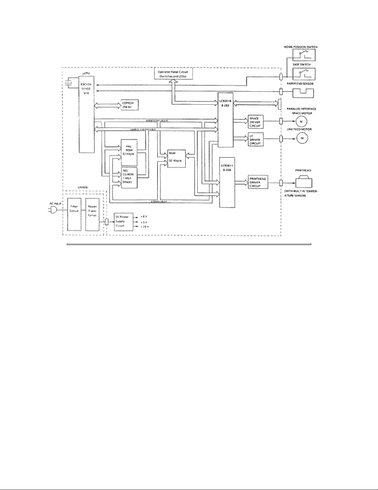
2.1.02 Microprocessor and Peripheral Circuits
Microprocessor (Q5: 83C154GS-551-V1K)
The microprocessor is the nucleus of the control circuit. Its peripheral circuits operate under program
control by this microprocessor. The I/O ports of the microprocessor are connected to the address bus,
data bus, and control lines.
Program ROM (Q2)
The program ROM (256 Kbit) contains the control program for the printer. The microprocessor operates
by execution of this program.
RAM (Q4)
The RAM stores received data (to be printed). (32 Kbytes)
CGROM (Q3)
1 MBit ROM which stores the resident character fonts.
EEPROM (Q18)
This 256-bit serial Electrically Erasable and Programmable ROM stores the Menu Mode data.
LSI (Q7: LC92018B-283)
This LSI switches the phase of the space motor, and generates the timing of print dots for each print
density. The LSI performs the following functions.
Space Pulse Motor Control
To obtain the carriage speed instructed by the microprocessor, the LSI generates the pulse switch timing
and overdrive time.
Dot Timing generation
Parallel Interface Control
LF Motor Control
LED Drive
General Purpose Input Port
Used to read Operator Board Switches.
LSI (Q6: LC92011B-284)
This LSI drives the 24 pin printhead and controls memory. The following describes the function of the LSI.
Printhead Drive Control
Head Pin Counting Function
Counts the number of printwires to be driven then, changes the duration of the HD ON signal accordingly.
Memory Control
Extends the addressable memory by switching banks in/out.
LED Drive Output Port
Microline 380 Block Diagram
Page 25
Copyright 1997, Okidata, Division of OKI America, Inc. All rights reserved. See the OKIDATA Business
Partner Exchange (BPX) for any updates to this material. (http://bpx.okidata.com)
Page 26

Page: 16
Service Guide ML380
Chapter 2 Principles of Operation
2.1.03 Initialization
The printer is initialized whenever it is powered ON or when the I-PRIME signal is received at the parallel
interface. Initialization is started when the RST-P signal is sent from the reset circuit (Q8:Pin 1) to Q5, Q6
and Q7.
When RST-P is generated, ROM program execution starts with the mode setting of Q5, Q6 and Q7. Next,
ROM and RAM are checked for errors, RAM is initialized and the carriage is homed. The program finally
establishes the Interface signals (output level of ACK, BUSY, etc.), switches the SELECT indicator ON,
and informs the host computer that the printer is ready to receive data.
Copyright 1997, Okidata, Division of OKI America, Inc. All rights reserved. See the OKIDATA Business
Partner Exchange (BPX) for any updates to this material. (http://bpx.okidata.com)
Page 27
Page: 17
Service Guide ML380
Chapter 2 Principles of Operation
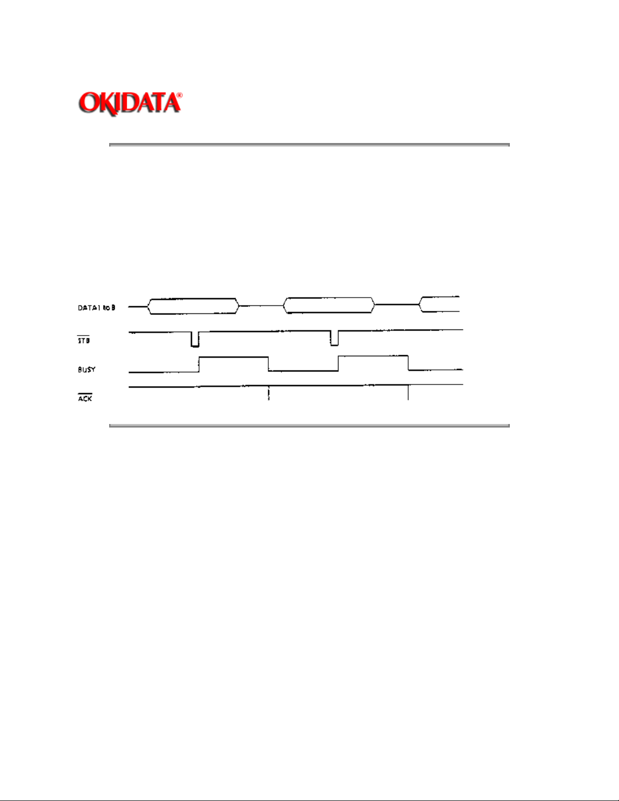
2.1.04 Interface Control
Parallel Interface
The data from the interface is received through connector (CN-1) and the Interface LSI (Q7) latches this
data in sync with the STB signal.
The BUSY signal is switched ON as the data is processed. When processing is completed, the BUSY
signal is switched OFF and an ACK signal is sent to the host to request more data.
The BUSY signal is also switched ON when the printer is not able to receive data (buffer is full, printer is
deselected or an error condition exists).
Copyright 1997, Okidata, Division of OKI America, Inc. All rights reserved. See the OKIDATA Business
Partner Exchange (BPX) for any updates to this material. (http://bpx.okidata.com)
Page 28
Page: 18
Service Guide ML380
Chapter 2 Principles of Operation
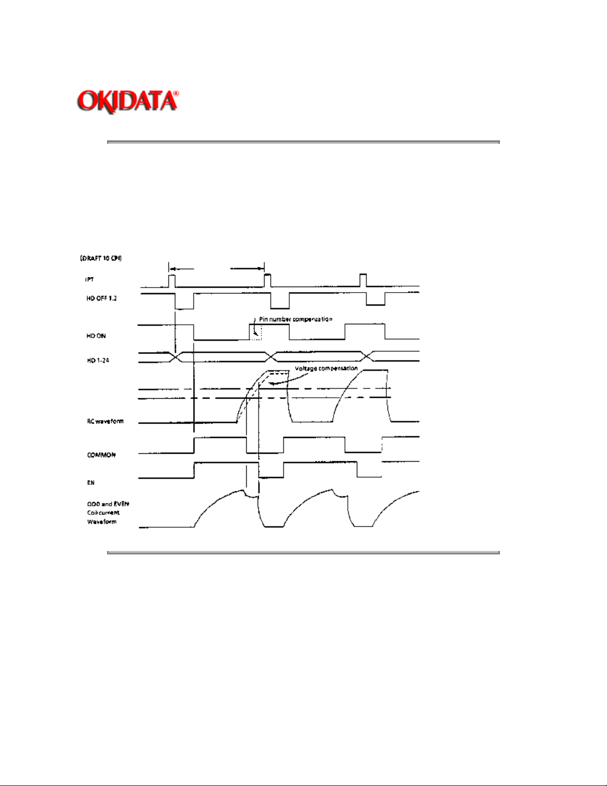
2.1.05 Printhead Drive Circuit
This circuit is used to drive the 24 print wires. The signals HD1 through HD24 control the individual print
wires. The HD ON signal (even/odd trigger) enables the drive circuit when printing is desired. The head
drive duration is determined by an RC integrating circuit which modifies the HD ON pulsewidth. The
pulsewidth of the HD ON signal varies with the number of pins being driven. The drive time increases as
more pins are driven, and decreases as fewer pins are driven. The RC circuit compensates for the
fluctuation of drive voltage (+35 vdc).
Copyright 1997, Okidata, Division of OKI America, Inc. All rights reserved. See the OKIDATA Business
Partner Exchange (BPX) for any updates to this material. (http://bpx.okidata.com)
Page 29

Page: 19
Service Guide ML380
Chapter 2 Principles of Operation
2.1.06 Spacing Drive Circuit
The space motor is driven by a two-phase pulse motor.
The phase signals (Phase 1, Phase 2, Phase 3 and Phase 4) and the basic pulse signals are output from
the LSI (Q7). The pulse signals are modified by the drive voltage compensation circuit and sent back to
the LSI (Q7).
The space overdrive signals (Phase 1DVOV, Phase 2 DVOV, Phase 3DVOV and Phase 4DVOV) switch
Q16 and Q17 ON, setting up the proper phase relationship of analog space motor drive signals (SP Phase
1 through SP Phase 4). These signals are then sent to the space motor.
Copyright 1997, Okidata, Division of OKI America, Inc. All rights reserved. See the OKIDATA Business
Partner Exchange (BPX) for any updates to this material. (http://bpx.okidata.com)
Page 30
Page: 20
Service Guide ML380
Chapter 2 Principles of Operation
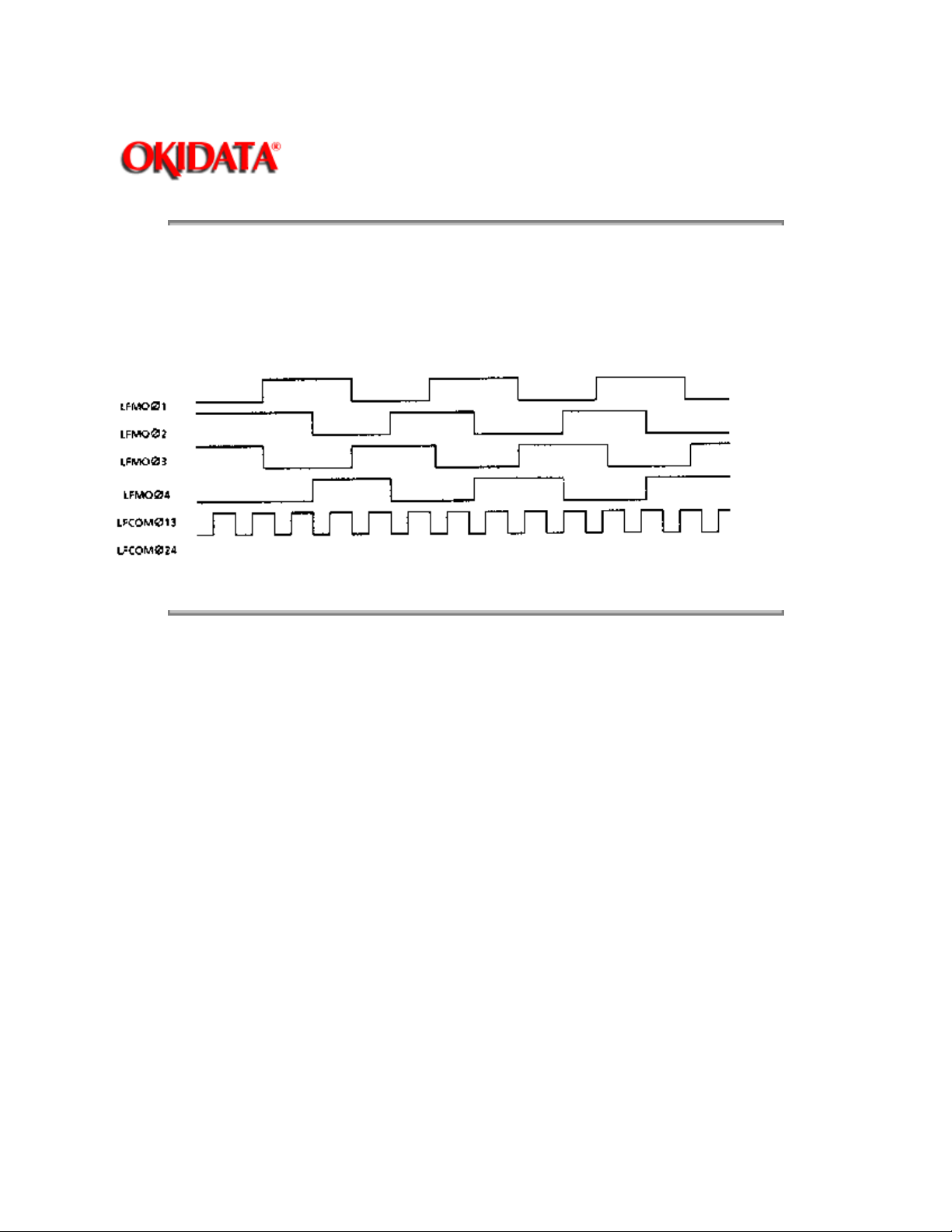
2.1.07 Line Feed Circuit
The line feed motor shaft is held stationary by + 8 vdc (the holding current is approximately 30 ma)
whenever in a stopped position.
During line feed operation, the line feed motor is driven in accordance with the LF OVD signal. The signals
LFMO Phase 1 through LFMO Phase 4 establish the proper phase relationship for driving the motor.
Copyright 1997, Okidata, Division of OKI America, Inc. All rights reserved. See the OKIDATA Business
Partner Exchange (BPX) for any updates to this material. (http://bpx.okidata.com)
Page 31

Page: 21
Service Guide ML380
Chapter 2 Principles of Operation
2.1.08 Alarm Circuits
Fault Alarm Circuit (in Power Supply Unit)
This protective circuit causes the AC fuse to open when a fault occurs in the printhead drive circuit or line
feed drive circuit, thus preventing component failure.
To accomplish this, the circuit monitors the overdrive signal of each drive circuit. If the duration of any
drive circuit exceeds a predetermined time, the appropriate signal (HEAD ALM, LF ALM1 or LF ALM2) will
be sent to the fault alarm circuit. The fault alarm circuit generates the ALM signal (high), which switches
on an SCR.
This causes the secondary coil (40 volts) of the main transformer to short-circuit, causing an overcurrent
to flow through the primary coil and open the AC fuse.
Printhead Overheat Alarm Circuit
In order to protect the printhead coils, this circuit monitors the printhead temperature by using a thermistor
contained in the printhead. The CPU senses this circuit every time a line is printed.
Whenever printing, the printhead temperature increases. If the head temperature reaches approximately
90 degrees - 129 degrees Celsius, a head overheat ALARM 1 is generated. When ALARM 1 is detected,
bi-directional printing stops. Uni-directional printing begins.
If the printhead temperature continues to increase (130 degrees Celsius), ALARM 2 is generated. Printing
stops until the head temperature decreases. When the head temperature drops below the ALARM 1
threshold, printing resumes.
Low DC Voltage Detection Circuit
The + 35 vdc drive voltage is monitored for a low voltage condition during each print operation. If the + 35
vdc drops, the negative terminal input voltage of the comparator (Q8) decreases, the comparator reverses
state, and the DC LOW-P signal is switched ON.
When the signal DC LOW-P is active, printing is accomplished by using twelve of the twenty-four
printwires in a dual-pass print.
Copyright 1997, Okidata, Division of OKI America, Inc. All rights reserved. See the OKIDATA Business
Partner Exchange (BPX) for any updates to this material. (http://bpx.okidata.com)
Page 32

Page: 22
Service Guide ML380
Chapter 2 Principles of Operation
2.1.09 Paper End Detection Circuit
PAPER END is detected by a photosensor. When the printer detects an out-of-paper condition, the PEN
signal goes low, printing is stopped, and the ALARM LAMP is switched ON.
Copyright 1997, Okidata, Division of OKI America, Inc. All rights reserved. See the OKIDATA Business
Partner Exchange (BPX) for any updates to this material. (http://bpx.okidata.com)
Page 33

Page: 23
Service Guide ML380
Chapter 2 Principles of Operation
2.1.10 Power Supply
The power supply consists of the power transformer, the filter board and the DC power supply circuit on
the control board.
The AC input voltage is transformed into 8.6 VAC and 46 VAC by the power transformer. These AC
voltages are converted to + 8 vdc, + 5 vdc and + 35 vdc levels by the DC power supply circuit on the
control board. The + 5 vdc is a regulated voltage.
Filter Board
The filter board consists of the power switch, AC fuse and AC noise filter.
Power Transformer
If the internal temperature of the power transformer rises abnormally, the built-in temperature fuse will
open to prevent any damage to other electrical components.
NOTE:
If the temperature fuse in the transformer opens, the transformer must be replaced.
Power Supply Circuit
Converts the AC Voltage input to + 8 vdc, + 5 vdc and + 35 vdc and supplies it to the control board. This
circuit also regulates the + 5 vdc.
Copyright 1997, Okidata, Division of OKI America, Inc. All rights reserved. See the OKIDATA Business
Partner Exchange (BPX) for any updates to this material. (http://bpx.okidata.com)
Page 34

Page: 24
Service Guide ML380
Chapter 2 Principles of Operation
2.2 MECHANICAL OPERATION
2.2.01 Printhead Mechanism
The Microline 380 uses a highly efficient stored energy type printhead. Power is not consumed until the
printwires are activated, thereby extending the printhead life to approximately 200 million characters.
The printhead uses 24 printwires (two columns of 12 wires each). Each wire is welded to an armature.
Behind this armature is a spacer ring.
Each of the 24 printwire armatures have a permanent magnet behind them. The magnets attract the
armatures, drawing the printwires into the wire guide, thus keeping the wires inside the printhead. A coil is
wrapped around each of the permanent magnets.
When a dot is to be printed, current is passed through the appropriate coil. This creates a magnetic field
which counters the magnetic field of the permanent magnet. The armature can then spring forward and
the print wire (which is attached to the armature) strikes the ribbon and imprints a dot on the paper.
When current is removed from the coil, the magnetic field of the permanent magnet attracts the armature,
causing the printwire to retract into the wire guide once again.
The printhead contains a built-in thermistor used to monitor the printhead temperature.
The printhead is composed of the following parts.
Wire Guide
Print Wires
Armature Assembly
Yoke
Spring
Spacer
Magnet Assembly
Thermistor
Printed Circuit Board
Page 35

Page 36

Copyright 1997, Okidata, Division of OKI America, Inc. All rights reserved. See the OKIDATA Business
Partner Exchange (BPX) for any updates to this material. (http://bpx.okidata.com)
Page 37

Page: 25
Service Guide ML380
Chapter 2 Principles of Operation
2.2.02 Spacing
Spacing is performed when the main shaft (installed in parallel with the platen), and carriage (mounted on
the space rack) are driven by the pulse motor.
Spacing involves the parts listed below.
Pulse Motor
Drive Pulley
Idle Pulley
Carriage Shaft
Carriage Frame
Space Rack
Spacing Operation
The carriage containing the printhead moves parallel to the platen along the main carriage shaft and
space rack. Power from the space motor is transferred via the mini-pitch belt, which is attached to the
bottom of the carriage frame. When the pulse motor rotates clockwise (as viewed from above), the driving
force is transmitted to the mini pitch belt through the drive pulley, and the carriage moves from left to right.
The carriage is designed to move 0.8 inch when the pulse motor performs one rotation.
Head Gap Adjusting
The head gap adjusting mechanism adjusts the gap between the platen and printhead. This is
accomplished by moving the adjusting lever on the left side of the printer mechanism. When the lever is
moved, the carriage shaft rotates. Since the carriage shaft is attached to the printer mechanism with
eccentric collars, as the carriage shaft rotates, the distance between the platen and carriage shaft
changes.
Page 38

Copyright 1997, Okidata, Division of OKI America, Inc. All rights reserved. See the OKIDATA Business
Partner Exchange (BPX) for any updates to this material. (http://bpx.okidata.com)
Page 39

Page: 26
Service Guide ML380
Chapter 2 Principles of Operation
2.2.03 Ribbon Drive
The ribbon drive mechanism moves the ribbon in synchronization with the space motor operation.
The ribbon drive mechanism consists of the following items.
Ribbon Drive Gear assembly
Space Rack
Ribbon Cartridge
Ribbon Cartridge
An endless ribbon with a single direction feed is used. Ink is supplied from an ink tank, which is built into
the ribbon cartridge.
Ribbon Feed Operation
The rotation of the space pulse motor is transmitted to the drive gear in the ribbon cartridge through the
space rack and ribbon feed gear assembly, thereby feeding the ink ribbon.
The feed direction of the ribbon is maintained by switching the rotational direction of the gears in the
ribbon drive assembly. This ensures uni-directional ribbon movement when bi-directional printing is used.
Copyright 1997, Okidata, Division of OKI America, Inc. All rights reserved. See the OKIDATA Business
Partner Exchange (BPX) for any updates to this material. (http://bpx.okidata.com)
Page 40

Page: 27
Service Guide ML380
Chapter 2 Principles of Operation
2.2.04 Paper Feed
Paper feeding is performed by turning the platen and the pin tractor. The tractor is driven by the line feed
pulse motor.
The paper feed mechanism consists of the following items.
Pulse motor with gears
Idler Gear
Change Spring
Change Gear
Platen
Tractor Feed Unit
Pressure Roller Assembly
Friction Feed
When the release lever is set to the FRICTION FEED position, the change gear is disengaged from the
tractor gear. At the same time, the release lever applies pressure to push the pressure rollers against the
platen, allowing paper to be fed.
Tractor Feed
When the release lever is set to the TRACTOR FEED position, the release lever allows the reset spring to
push the change gear toward the tractor gear. At the same time, the release lever pushes the pressure
rollers away from the platen, allowing paper to be fed by the tractors.
NOTE:
Drive power from the line feed motor is transferred from the platen to the idler gear and then to the change
gear.
Page 41

Copyright 1997, Okidata, Division of OKI America, Inc. All rights reserved. See the OKIDATA Business
Partner Exchange (BPX) for any updates to this material. (http://bpx.okidata.com)
Page 42

Page: 28
Service Guide ML380
Chapter 2 Principles of Operation
2.2.05 Paper-End Detection
Continuous Sheet Paper-End
When continuous sheet paper is installed, the paper moves the continuous sheet paper-end lever to A1
and the sensor is switched ON. When out of continuous sheet paper, the paper-end lever moves to
position B1 and the sensor is switched OFF indicating a paper-end condition.
Bottom Feed Paper-End
When paper is installed, it moves the bottom paper-end lever to position A2 and the sensor is switched
ON. When a paper out condition exists, the bottom paper-end lever moves to position B2 and the sensor
is switched OFF, indicating a paper-end condition.
Cut-Sheet Paper-End
When cut-sheet paper is installed, the paper moves the cut-sheet paper-end lever to position A3 and the
sensor is ON. At the end of printing, the cut-sheet paper-end lever moves to position B3 and the sensor is
switched OFF, indicating a paper-end condition.
Page 43

Copyright 1997, Okidata, Division of OKI America, Inc. All rights reserved. See the OKIDATA Business
Partner Exchange (BPX) for any updates to this material. (http://bpx.okidata.com)
Page 44

Page: 29
Service Guide ML380
Chapter 2 Principles of Operation
2.2.06 Semi-Automatic Sheet Feeder (SASF)
The Semi-Automatic Sheet Feeder (SASF) is used to automatically set the print start position when using
cut-sheet or continuous sheet paper.
The procedure is as follows.
Cut-Sheet SASF
1. Push the paper release lever to the cut-sheet side (rear of printer).
2. Insert the paper from behind the platen.
3. Open the paper bail arm (pull toward the front of the printer). This activates the SASF switch.
4. Line feed operation will feed the paper 2.76 inches.
If the paper does not move, the SASF motion becomes invalid and is treated like an ordinary paper-end.
5. Once the paper bail arm is closed, a reverse line feed of about 0.18 inches is performed. This moves
the paper to the print start position.
Continuous Sheet (Rear Feed) SASF
1. Push the paper release lever to the continuous sheet side (front of the printer).
2. Insert the paper into the push tractor.
3. Open the paper bail arm (pull toward the front of the printer). This activates the SASF switch.
4. Line feed operation will feed the paper 3.6 inches.
If the paper does not move within 2.4 inches of motion, the SASF motion becomes invalid and this is
treated like an ordinary paper-end.
5. Once the paper bail arm is closed, a reverse line feed of about 0.18 inches is performed. This moves
the paper to the print start position.
Copyright 1997, Okidata, Division of OKI America, Inc. All rights reserved. See the OKIDATA Business
Partner Exchange (BPX) for any updates to this material. (http://bpx.okidata.com)
Page 45

Page: 30
Service Guide ML380
Chapter 2 Principles of Operation
2.2.07 Paper Park
Paper park operates as follows.
1. Press PAPER PARK.
2. Reverse line feed retracts the paper until a PAPER-END condition exists
or
14 inches of paper have been fed.
3. When the PAPER-END condition exists, the printer retracts 0.49 inches of paper. The paper is still
installed on the push tractor, but cut sheet paper may now be fed.
Copyright 1997, Okidata, Division of OKI America, Inc. All rights reserved. See the OKIDATA Business
Partner Exchange (BPX) for any updates to this material. (http://bpx.okidata.com)
Page 46

Page: 31
Service Guide ML380
Chapter 3 Maintenance & Disassembly
3.1 OVERVIEW
3.1.01 General Information
This section lists the parts replacement, adjustment, cleaning, lubrication, and shipping procedures.
Disassembly should not be performed unless absolutely necessary.
malfunctioning printer until you have followed the failure analysis procedures in Section Four of this
Service Handbook.
NEVER
perform disassembly on a
Follow the procedures listed in
either consumable or parts are replaced. Failure to perform these procedures could result in unnecessary
service calls.
Proper performance of maintenance and cleaning will help to achieve the best possible print quality from
the printer.
Copyright 1997, Okidata, Division of OKI America, Inc. All rights reserved. See the OKIDATA Business
Partner Exchange (BPX) for any updates to this material. (http://bpx.okidata.com)
Adjustments and Service Settings
. Adjustments may be required when
Page 47

Chapter 3 Maintenance & Disassembly
3.1.02 Maintenance Tools
The following tools are required to service the printer.
#2 Phillips Screwdriver (with magnetic tip)
Straight-slot Screwdriver
Needle Nose Pliers (4 Inch)
Awl or large, opened paper clip
Wire Cutters
Digital Multimeter
Feeler Gauge (capable of measuring .014 inches)
Shop Vacuum
Clean, soft, and lint-free Cloth
All-Purpose Cleaner
Contact Kleen (Okidata P/N 51802301)
Platen Cleaner
Machine Grease
Machine Oil
Page: 32
Service Guide ML380
Copyright 1997, Okidata, Division of OKI America, Inc. All rights reserved. See the OKIDATA Business
Partner Exchange (BPX) for any updates to this material. (http://bpx.okidata.com)
Page 48

Page: 33
Service Guide ML380
Chapter 3 Maintenance & Disassembly
3.1.03 Maintenance Precautions
1. Do not disassemble the unit if it is operating normally.
2. Before starting disassembly and assembly, always turn the AC power switch OFF and pull out the AC
plug.
3. Detach the interface cable, if installed.
4. Do not remove parts unnecessarily. Try to keep disassembly to a minimum.
5. Use the recommended maintenance tools.
6. When disassembling, follow the listed sequence. Failure to follow the correct sequence may result in
damaged parts.
7. Since screws, collars and other small parts are easily lost, they should be temporarily attached to the
original positions.
8. When handling circuit boards use extreme care. Integrated circuits (microprocessors, ROM, and RAM)
can be destroyed by static electricity.
9. Do not place printed circuit boards directly on conductive surfaces.
10. Follow the recommended procedures when replacing assemblies and units.
11. Perform the printhead gap adjustment procedure when any of the following occur.
3.3 of this Service Handbook.
Print Quality is darker on one side of the document.
Parts are replaced.
Printhead (3.2.02)
Space Rack (3.2.04)
Carriage Frame (3.2.13)
12. Perform the space belt tension adjustment procedure when the following parts are installed.
Refer to Section 3.3 of this Service Handbook.
Space Belt (3.2.06)
Space Motor Assembly (3.2.22)
Copyright 1997, Okidata, Division of OKI America, Inc. All rights reserved. See the OKIDATA Business
Partner Exchange (BPX) for any updates to this material. (http://bpx.okidata.com)
Refer to Section
Page 49

Page: 34
Service Guide ML380
Chapter 3 Maintenance & Disassembly
3.2 DISASSEMBLY/ASSEMBLY PROCEDURES
General Information
This section contains the printer disassembly procedures. Only the removal procedures are explained
here. Reverse the procedure for the installation.
At the bottom of each procedure is a listing of the parts covered in that procedure. The Okidata part
number, item description, comment (RSPL, Option, Consumable) and cross-reference to Appendix B is
provided for each part. Items included in the Recommended Spare Parts List are indicated by the acronym
RSPL. N/A will appear where a part number is not available.
Part Item Comment Appendix B Number Description Reference
This Service Handbook lists the disassembly procedures for major components of the unit. Okidata DOES
NOT recommend disassembling a unit which is operating normally. If you decide to perform disassembly
only
during this training, Okidata recommends that you perform
items. All other procedures are provided to assist you in identifying parts. It is not likely that you will
perform these procedures while servicing the unit.
the disassembly procedures for RSPL
Be sure to read all notes, cautions, and warnings, as they contain important information regarding
disassembly / assembly.
Copyright 1997, Okidata, Division of OKI America, Inc. All rights reserved. See the OKIDATA Business
Partner Exchange (BPX) for any updates to this material. (http://bpx.okidata.com)
Page 50

Service Guide ML380
Chapter 3 Maintenance & Disassembly
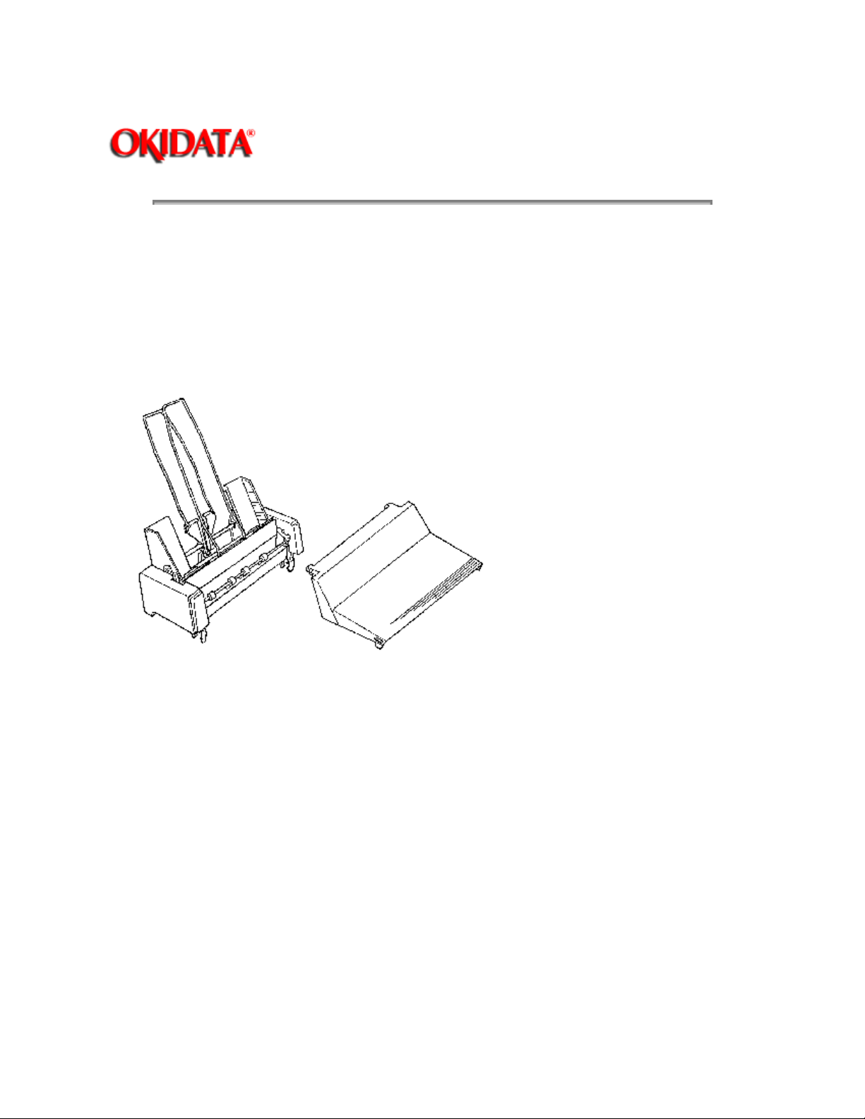
3.2.01 Paper Separator
1. Raise the access cover (1).
2. Move the bail lever (2) toward the front of the printer.
3. Push the paper separator (3) at location A and release it from the platen shaft (4).
4. Lift the paper separator to detach the guide pins (5) from the printer mechanism (6).
P/N N/A AC Cable B.2.03
P/N 53511401 Separator: Paper RSPL B.2.03
Page: 35
Copyright 1997, Okidata, Division of OKI America, Inc. All rights reserved. See the OKIDATA Business
Page 51

Partner Exchange (BPX) for any updates to this material. (http://bpx.okidata.com)
Page 52

Page: 36
Service Guide ML380
Chapter 3 Maintenance & Disassembly
3.2.02 Printhead
1. Move the bail lever (1) to back of the printer.
2. Remove the ribbon cartridge (2).
3. Grasp the tab of the head clamp (3), lift up and swing it 90° in the direction of Arrow A to unlock the
printhead (4).
4. Lift the printhead from the carriage frame (5).
NOTE:
Perform the printhead gap adjustment procedure after installing this part.
Refer to Section 3.3 of this Service Handbook.
P/N 52104001 Ribbon: Cartridge Consumable B.2.08
P/N 50079301 Printhead RSPL B.2.03
Page 53

Copyright 1997, Okidata, Division of OKI America, Inc. All rights reserved. See the OKIDATA Business
Partner Exchange (BPX) for any updates to this material. (http://bpx.okidata.com)
Page 54

Service Guide ML380
Chapter 3 Maintenance & Disassembly
3.2.03 Upper Cover Assembly
1. Perform this procedure: 3.2.01.
2. Remove the platen knob (1).
3. Raise the sheet separator (2), and pull it out diagonally in the direction of Arrow A.
4. Do the following to avoid interference when removing the upper cover assembly.
Close the covers of the tractor assemblies (3).
Slide the assemblies to the center of the printer unit.
5. Remove the two screws (4). The screws are at the back of printer, on the bottom.
6. Lift the rear part of the upper cover (5), pull it forward, and remove it.
7. Raise the access cover (6) 90° and remove it from the upper cover.
Page: 37
P/N 50071101 Separator: Sheet (Assembly) RSPL B.2.02
P/N 50071201 Separator: Sheet B.2.02
P/N 53510201 Support: Sheet B.2.02
P/N 51901101 Knob: Platen RSPL B.2.03
P/N 53510401 Guide: Sheet (L) B.2.02
P/N 53510301 Guide: Sheet (R) B.2.02
P/N 53510101 Cover: Access RSPL B.2.02
P/N 53510001 Cover: Middle RSPL B.2.02
Page 55

Page 56

Copyright 1997, Okidata, Division of OKI America, Inc. All rights reserved. See the OKIDATA Business
Partner Exchange (BPX) for any updates to this material. (http://bpx.okidata.com)
Page 57

Page: 38
Service Guide ML380
Chapter 3 Maintenance & Disassembly
3.2.04 Space Rack
1. Perform this procedure: 3.2.02.
2. Remove the two screws (1) on the carriage plate (2). Do not remove the ribbon feed gear assembly.
3. Slide the carriage frame (3) in the direction of Arrow A, leaving the carriage plate in place.
4. Set the carriage plate under the space rack (4).
5. Release the claw (5).
6. Remove the B side of the space rack from the guide pin (6), and lift the space rack.
7. Remove the C side of the space rack from guide pin (7), and remove the space rack.
NOTE:
Perform the printhead gap adjustment procedure after installing this part.
Refer to Section 3.3 of this Service Handbook.
P/N 53510801 Rack: Space RSPL B.2.04
Page 58

Copyright 1997, Okidata, Division of OKI America, Inc. All rights reserved. See the OKIDATA Business
Partner Exchange (BPX) for any updates to this material. (http://bpx.okidata.com)
Page 59

Page: 39
Service Guide ML380
Chapter 3 Maintenance & Disassembly
3.2.05 Ribbon Feed Gear Assembly
1. Perform this procedure: 3.2.02.
2. Release the four claws (1).
3. Insert a screwdriver into the grooves (2) and pry the claws away from the carriage plate (3).
4. Lift the ribbon feed gear assembly (4) in the direction of arrow A. Slide it in the direction of Arrow B, and
remove it.
P/N 50071501 Gear: Ribbon Feed (Assembly) RSPL B.2.06
Page 60

Copyright 1997, Okidata, Division of OKI America, Inc. All rights reserved. See the OKIDATA Business
Partner Exchange (BPX) for any updates to this material. (http://bpx.okidata.com)
Page 61

3.2.06 Mini-Pitch (Space) Belt
Page: 40
Service Guide ML380
Chapter 3 Maintenance & Disassembly
1. Perform these procedures: 3.2.02
2. Use pliers to remove the belt tension spring (1).
3. Loosen the screw (2).
4. Remove the belt (3) from the idle pulley (4).
5. Remove the head connector assembly (5) from the carriage plate (6).
6. Remove the carriage plate.
7. Detach the belt from the space motor assembly gear (7).
8. Remove the belt clamp (8) mounted to bottom of the carriage plate.
9. Use a screwdriver to push the claw of the belt clamp in the direction of arrow A. Then, remove the belt
clamp and belt by lowering the claw in the direction of arrow B.
and 3.2.05.
NOTE:
Perform the space belt tension adjustment procedure after installing this part.
Refer to Section 3.3 of this Service Handbook.
P/N 50904801 Spring: Coil RSPL B.2.04
P/N 51304001 Belt: Mini-Pitch (Space Belt) RSPL B.2.06
P/N N/A Screw: Self Tapping B.2.04
P/N 51004001 Slider RSPL B.2.06
P/N 51219201 Pulley: Idle RSPL B.2.04
P/N 53330401 Plate: Carriage RSPL B.2.06
P/N 50704701 Clamp: Belt RSPL B.2.06
P/N 53330301 Bracket: Idle Pulley RSPL B.2.04
Page 62

Copyright 1997, Okidata, Division of OKI America, Inc. All rights reserved. See the OKIDATA Business
Partner Exchange (BPX) for any updates to this material. (http://bpx.okidata.com)
Page 63

3.2.07 Head Connector Assembly
Page: 41
Service Guide ML380
Chapter 3 Maintenance & Disassembly
1. Perform these procedures: 3.2.01
2. Remove the two head cables (1) from the connectors (2) on the control board. When cable clamp (3) is
lifted, the head cables can be removed.
3. Pull the head cables under the cable guides (4), and remove the head cables.
P/N 56725301 Connector: Head (Assembly) RSPL B.2.06 Head Cable
, 3.2.02 , 3.2.03 , 3.2.05 , and 3.2.06 .
Page 64

Copyright 1997, Okidata, Division of OKI America, Inc. All rights reserved. See the OKIDATA Business
Partner Exchange (BPX) for any updates to this material. (http://bpx.okidata.com)
Page 65

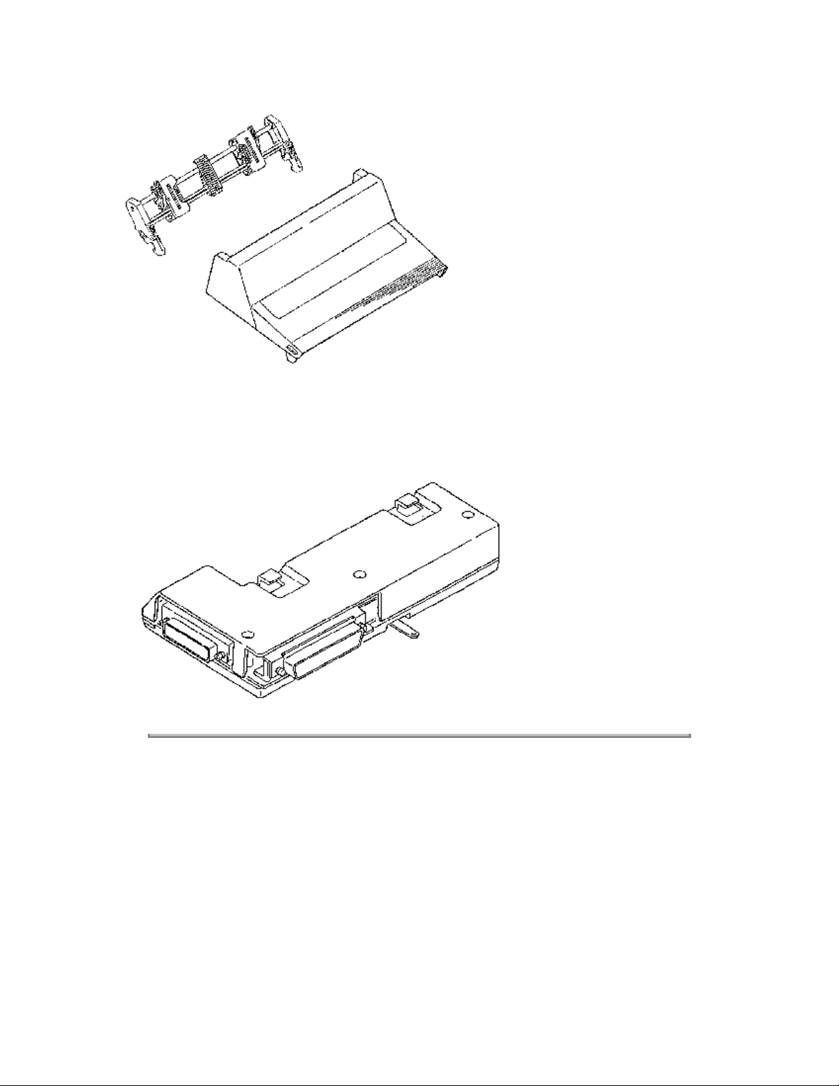
3.2.08 Main Control Board (UMMB)
Page: 42
Service Guide ML380
Chapter 3 Maintenance & Disassembly
1. Perform these procedures: 3.2.01
2. Remove the five connectors (1) connected to the control board (2).
3. Remove the five screws (3).
4. Release the two claws (4), and move the control board in the direction of arrow A to remove.
P/N 55047801 PCB: UMMB (Main Control) RSPL B.2.03
P/N 55938501 IC: EEPROM BR93CS46-Z-NW RSPL B.2.03
P/N 56304201 Fuse: 125V 1.6A RSPL B.2.03
P/N 56304301 Fuse: 125V 2.5A RSPL B.2.03
and 3.2.03 .
w/o ROM
Page 66

Copyright 1997, Okidata, Division of OKI America, Inc. All rights reserved. See the OKIDATA Business
Partner Exchange (BPX) for any updates to this material. (http://bpx.okidata.com)
Page 67

3.2.09 Operation Panel
Page: 43
Service Guide ML380
Chapter 3 Maintenance & Disassembly
1. Perform these procedures: 3.2.01
2. Use a screwdriver to release the six claws (1) on the operation panel (2) and remove the operation
panel from the control board (3).
P/N 53524301 Sheet: Operation Panel RSPL B.2.03
and 3.2.03 .
Copyright 1997, Okidata, Division of OKI America, Inc. All rights reserved. See the OKIDATA Business
Partner Exchange (BPX) for any updates to this material. (http://bpx.okidata.com)
Page 68

3.2.10 Line Feed Motor
Page: 44
Service Guide ML380
Chapter 3 Maintenance & Disassembly
1. Perform these procedures: 3.2.01
2. Use a screwdriver to open the lock levers (1) in the directions of arrows A and B, and push the bracket
(2) of the line feed motor (3) in the direction of arrow C.
3. Pull the line feed motor out of the guide holes (4), in the direction of arrow D.
NOTE:
After installation, check that the platen gear (5) engages firmly and rotates smoothly.
P/N 56507801 Motor: Line Feed RSPL B.2.04
and 3.2.02 .
Copyright 1997, Okidata, Division of OKI America, Inc. All rights reserved. See the OKIDATA Business
Partner Exchange (BPX) for any updates to this material. (http://bpx.okidata.com)
Page 69

3.2.11 Photosensor Assembly (Paper End)
Page: 45
Service Guide ML380
Chapter 3 Maintenance & Disassembly
1. Perform these procedures: 3.2.01
2. Pull the paper end sensor (1) from the sensor guide (2).
P/N 56106901 Photosensor: (Assembly) RSPL B.2.04 Paper End
, 3.2.02 and 3.2.10 .
Copyright 1997, Okidata, Division of OKI America, Inc. All rights reserved. See the OKIDATA Business
Partner Exchange (BPX) for any updates to this material. (http://bpx.okidata.com)
Page 70

3.2.12 Bail Arms
Page: 46
Service Guide ML380
Chapter 3 Maintenance & Disassembly
1. Perform these procedures: 3.2.01
2. Use pliers to remove the left bail arm spring (1).
3. Push claw (2) downward, pull it out of guide hole (3) of main frame and remove the left bail arm (4).
4. Remove the left bail arm from the bail bar (5).
5. Use pliers to remove the right bail arm spring.
6. Push claw downward, pull it out of guide hole of main frame and remove the right bail arm.
7. Remove the right bail arm from the bail bar.
P/N 50911801 Spring: Bail Arm (L) RSPL B.2.04
P/N 53511001 Bail Arm (L) RSPL B.2.04
P/N 50911701 Spring: Bail Arm (R) RSPL B.2.04
P/N 53511101 Bail Arm (R) RSPL B.2.04
P/N 51110501 Shaft: Indicator (Assembly) RSPL B.2.04 Bail Bar
, 3.2.02 , 3.2.10 , and 3.2.11 .
Page 71

Copyright 1997, Okidata, Division of OKI America, Inc. All rights reserved. See the OKIDATA Business
Partner Exchange (BPX) for any updates to this material. (http://bpx.okidata.com)
Page 72

3.2.13 Carriage Frame
Page: 47
Service Guide ML380
Chapter 3 Maintenance & Disassembly
1. Perform these procedures: 3.2.01
2. Open the supporting point A, and remove the head clamp (1).
3. Insert a screwdriver into the groove of carriage frame (2), and remove ribbon protector (3).
4. Turn the white left adjust bushing (4) to the lower end, and remove it.
5. Turn the black right adjust bushing (5) to the lower end, and remove it.
6. Turn the blue adjusting lever (6) to the lower end.
7. Slide the carriage shaft (7) to the right.
8. Remove the shaft and the adjusting lever.
9. Pull the carriage shaft in the direction of arrow B, and remove it from the carriage frame (8). Be
careful not to lose the eccentric collar (9). When installing the eccentric collar, place notched section (10)
toward the carriage shaft.
, 3.2.02 , and 3.2.03 .
NOTE:
Perform the printhead gap adjustment procedure after installing this part.
Refer to Section 3.3 of this Service Handbook.
P/N 50702901 Clamp: Head RSPL B.2.06
P/N 53056201 Protector: Ribbon RSPL B.2.06
P/N 53330201 Frame: Carriage RSPL B.2.06
P/N 51606501 Bushing: Adjust (L) RSPL B.2.04
P/N 51606601 Bushing: Adjust (R) RSPL B.2.04
P/N 53510701 Lever: Adjust RSPL B.2.04
P/N 51110401 Shaft: Carriage RSPL B.2.04
P/N 50704601 Collar: Eccentric RSPL B.2.04
P/N N/A Code: Earth B.2.04
Page 73

Copyright 1997, Okidata, Division of OKI America, Inc. All rights reserved. See the OKIDATA Business
Partner Exchange (BPX) for any updates to this material. (http://bpx.okidata.com)
Page 74

3.2.14 Platen Assembly
Page: 48
Service Guide ML380
Chapter 3 Maintenance & Disassembly
1. Perform these procedures: 3.2.01
2. Pull lock levers (1) in the direction of arrow A, and raising them at an angle of 90°. This releases the
platen assembly (2) from the main frame (3).
3. Lift the A side of the platen assembly until the B side clears the release lever (4).
NOTES:
After installation, check that the platen gear engages firmly with the line feed motor gear and that the
platen rotates smoothly.
Set the release lever to OPEN (front) and check that the groove (5) of the paper chute firmly engages with
the groove (6) of the main frame. Then, lock the platen assembly.
P/N 50061305 Platen: (Assembly) RSPL B.2.04
and 3.2.03 .
Page 75

Copyright 1997, Okidata, Division of OKI America, Inc. All rights reserved. See the OKIDATA Business
Partner Exchange (BPX) for any updates to this material. (http://bpx.okidata.com)
Page 76

3.2.15 Pressure Roller Assembly
Page: 49
Service Guide ML380
Chapter 3 Maintenance & Disassembly
1. Perform these procedures: 3.2.01
2. Remove the paper chute (1). Be careful not to damage the grounding strap.
3. Open the claw (2), and remove the paper release lever (3).
4. Remove the change gear (4) and the spring (5).
5. Remove the idle gear (6).
6. Remove the boss (7) from the guide hole (8) of the main frame (9), and remove the release link (10).
7. Pull part A of the pressure roller assembly shaft (11) out of the main frame, in the direction of arrow B.
8. Pull the C part of the pressure roller assembly shaft out of the main frame in the direction of arrow D.
9. Remove the shaft.
, 3.2.03 and 3.2.14 .
NOTES:
Installation
Position the tab (12) of the paper chute firmly with the groove (13) of the main frame.
Engage the cut-sheet paper end lever (14), attached to bottom of paper chute, to the bottom paper end
lever (15) under the main frame, and install the paper chute.
The Kit: Idler/Change Gear (ML300) includes the change and idler gears. Order this kit when replacing
these parts.
P/N 50071701 Chute: Paper (Assembly) RSPL B.2.05
P/N 53511201 Lever: Release RSPL B.2.05
P/N 51219101 Gear: Change RSPL B.2.05
P/N 50915101 Spring: Change Gear RSPL B.2.05
P/N 58227501 Kit: Idler/Change Gear (ML300) RSPL B.2.05
P/N 51216001 Gear: Idler B.2.05
P/N 53511301 Link: Release RSPL B.2.05
P/N 50071601 Roller: Pressure (Assembly) RSPL B.2.05
Page 77

Copyright 1997, Okidata, Division of OKI America, Inc. All rights reserved. See the OKIDATA Business
Partner Exchange (BPX) for any updates to this material. (http://bpx.okidata.com)
Page 78

3.2.16 Paper Pressure Guide
Page: 50
Service Guide ML380
Chapter 3 Maintenance & Disassembly
1. Perform these procedures: 3.2.01
2. Working from the underside of the printer mechanism and using a screwdriver, detach the connection
hole section (1) from the projection (2) of the main frame (3). Begin at point A and end at point B.
3. Remove the paper pressure guide (4).
NOTE:
On installation, be sure to install the projections and guide plates (5) simultaneously.
P/N 50911501 Guide: Paper Pressure RSPL B.2.05
, 3.2.02 , 3.2.03 and 3.2.05 .
Page 79

Copyright 1997, Okidata, Division of OKI America, Inc. All rights reserved. See the OKIDATA Business
Partner Exchange (BPX) for any updates to this material. (http://bpx.okidata.com)
Page 80

Page: 51
Service Guide ML380
Chapter 3 Maintenance & Disassembly
3.2.17 Tractor Assembly
NOTE:
Horizontal movement of the left tractor is restricted by a stopper on the lower cover.
1. Perform these procedures: 3.2.01 and 3.2.03 .
2. Remove the tractor drive shaft locking clamp.
3. Open the claw (1), and remove the drive gear (2) from the groove (3) of the drive shaft (4).
4. Release the right groove (5) of the drive shaft from the guide (6) of the main frame.
5. Shift the groove in the direction of Arrows A and B. This releases the left part of the drive shaft from the
guide hole (7) of the main frame.
6. Push the left part of lock shaft (8), and move the groove (9) in the direction of Arrow C to release the
groove from the hole (10) in the main frame.
7. Shift the lock shaft (8) to the right, and move the shaft in the direction of Arrow D to remove the shaft
from the larger guide hole (11).
8. Push the left part of the tractor assembly in the direction of Arrow E, and remove the tractor assembly
(12) while pulling the drive shaft in the direction Arrow F. This moves the shaft out of the guide holes (13
and 14) of the printer frame.
9. Remove the center guide (15), the left pin tractor assembly (16), and the right pin tractor assembly (17)
from the two shafts (4) and (8).
NOTES:
Marks A (18) and B (19) of the left (20) and right pin tractors (21) must be aligned when installed.
Install the left pin tractor assembly to the left of the stopper on the lower cover. This limits movement and
correctly positions the paper against the paper end sensor.
P/N 50071901 Tractor: Pin [L] (Assembly) RSPL B.2.06
P/N 51216101 Gear: Tractor RSPL B.2.05
P/N 51003901 Guide: Center RSPL B.2.06
P/N 50071801 Tractor: Pin [R] (Assembly) RSPL B.2.06
P/N 51109503 Shaft: Drive RSPL B.2.06
P/N 51110601 Shaft: Lock RSPL B.2.06
Page 81

Copyright 1997, Okidata, Division of OKI America, Inc. All rights reserved. See the OKIDATA Business
Partner Exchange (BPX) for any updates to this material. (http://bpx.okidata.com)
Page 82

3.2.18 Microswitch Assembly (SASF)
Page: 52
Service Guide ML380
Chapter 3 Maintenance & Disassembly
1. Perform these procedures: 3.2.01
2. The microswitch assembly (1) is fastened to the frame on two pins. The first pin (2) is part of the switch.
The second pin (3) is part of the printer mechanism. The first pin must be released before the switch will
pivot on the second pin.
3. To release the first pin, use an opened paper clip to push the pin out of the hole. Access the hole from
the inside of the printer frame. Then, pivot the switch on the second pin, in the direction of arrow A, until
the switch clears the bracket (4).
4. Remove the microswitch assembly.
P/N 56211301 Microswitch: (Assembly) SASF RSPL B.2.05
and 3.2.03 .
Page 83

Copyright 1997, Okidata, Division of OKI America, Inc. All rights reserved. See the OKIDATA Business
Partner Exchange (BPX) for any updates to this material. (http://bpx.okidata.com)
Page 84

Service Guide ML380
Chapter 3 Maintenance & Disassembly
3.2.19 Microswitch Assembly (Home Position Switch)
Page: 53
1. Perform these procedures: 3.2.01
2. Open the switch clamp (1) and release the home position switch (2) from the pin (3).
3. Pull the switch through the opening (4) in the printer frame.
4. Release the cables from the guides on the frame.
5. Remove the microswitch assembly.
P/N 56211301 Microswitch: (Assembly) RSPL B.2.05 Home Position
and 3.2.03 .
Copyright 1997, Okidata, Division of OKI America, Inc. All rights reserved. See the OKIDATA Business
Partner Exchange (BPX) for any updates to this material. (http://bpx.okidata.com)
Page 85

3.2.20 Printer Mechanism
Page: 54
Service Guide ML380
Chapter 3 Maintenance & Disassembly
1. Perform these procedures: 3.2.01
2. Open the claws (1) of the lower cover assembly (2) and lift the printer mechanism (3) to remove it.
P/N 54148708 Screw: No. 3 x 8 MM Self Tapping RSPL B.2.02
P/N 53330101 Plate: Shield RSPL B.2.02
P/N 50071301 Cover: Lower (Assembly) RSPL B.2.03
P/N 53510601 Cover: Lower RSPL B.2.02
P/N 53452701 Foot: Rubber RSPL B.2.02
P/N 50071401 Chassis: Mechanism (Assembly) RSPL B.2.05
and 3.2.03 .
Copyright 1997, Okidata, Division of OKI America, Inc. All rights reserved. See the OKIDATA Business
Page 86

Partner Exchange (BPX) for any updates to this material. (http://bpx.okidata.com)
Page 87

3.2.21 Power Supply Unit
Page: 55
Service Guide ML380
Chapter 3 Maintenance & Disassembly
1. Perform these procedures: 3.2.01
2. Open the claws (1) and remove the AC power cord shock restraint (2).
3. Remove the two screws (3).
4. Remove the grounding cord (4) to the AC power cord (5).
5. Remove the grounding cord (6) to the transformer (7).
6. Remove the four screws (8).
7. Remove the transformer, the AC switch (9), and the AC power cord from the lower cover assembly
(10).
8. The power supply unit is made of the grounding cords, the transformer, the AC switch, and the
connector (11).
, 3.2.03 , and 3.2.20 .
NOTE:
Installation
Firmly insert the AC switch into the A and B guides of the lower cover. The side with the red line goes is
the front.
Be careful not to cover the grounding mark (12) when installing the grounding cords.
P/N 56408201 Power Supply Unit 120V RSPL B.2.03
P/N 56408301 Power Supply Unit 220/240V RSPL B.2.03
P/N 56304101 Fuse: 125V 3.15A RSPL B.2.03
P/N 56304501 Fuse: 250V 1.25A RSPL B.2.03
Page 88

Copyright 1997, Okidata, Division of OKI America, Inc. All rights reserved. See the OKIDATA Business
Partner Exchange (BPX) for any updates to this material. (http://bpx.okidata.com)
Page 89

3.2.22 Space Motor Assembly
Page: 56
Service Guide ML380
Chapter 3 Maintenance & Disassembly
1. Perform these procedures: 3.2.01
2. Raise the printer mechanism (1), and remove the space motor cord (2) from the guides (3).
3. Open the two claws (4) and pull the space motor assembly (5) in the direction of arrow A.
4. Remove the brackets (6) from the guide holes (7) of the main frame and remove the space motor
assembly.
NOTE:
Installation
On installation, align the brackets with guide holes and push the space motor assembly down until it snaps
into position under the two claws.
Perform the space belt tension adjustment procedure after installing this part.
Refer to Section 3.3 of this Service Handbook.
P/N 56507901 Motor: Space (Assembly) RSPL B.2.05
, 3.2.03 , and 3.2.20 .
Page 90

Copyright 1997, Okidata, Division of OKI America, Inc. All rights reserved. See the OKIDATA Business
Partner Exchange (BPX) for any updates to this material. (http://bpx.okidata.com)
Page 91

3.2.23 Bottom Paper Guide Lever
Page: 57
Service Guide ML380
Chapter 3 Maintenance & Disassembly
1. Perform these procedures: 3.2.01
2. Push the pin (1) of the bottom paper guide lever (2), and remove the pin from the guide hole (3) of the
main frame.
3. Remove the pin (4) from the guide hole (5) of the main frame, and remove the bottom paper guide
lever.
NOTE:
When the paper chute (6) is installed, the cut-sheet paper end lever (7) must engage firmly with the
bottom paper guide lever.
P/N 53510901 Lever: Bottom Paper Guide RSPL B.2.05
, 3.2.03 and 3.2.20 .
Copyright 1997, Okidata, Division of OKI America, Inc. All rights reserved. See the OKIDATA Business
Page 92

Partner Exchange (BPX) for any updates to this material. (http://bpx.okidata.com)
Page 93

Page: 58
Service Guide ML380
Chapter 3 Maintenance & Disassembly
3.3 PRINTER ADJUSTMENTS
3.3.01 General Information
This section contains the procedures for performing adjustments on the printer. These procedures may be
required when replacing either consumables or parts. The disassembly/assembly procedures list the
required adjustments and refer you to this section. Failure to perform these procedures may result in
unnecessary service calls.
Copyright 1997, Okidata, Division of OKI America, Inc. All rights reserved. See the OKIDATA Business
Partner Exchange (BPX) for any updates to this material. (http://bpx.okidata.com)
Page 94

Service Guide ML380
Chapter 3 Maintenance & Disassembly
3.3.02 Gap Between Platen and Printhead
General Information
The printhead gap adjustment should be performed when the following occur.
1. Print quality is darker on one side of the document.
2. Parts are replaced.
Printhead (3.2.02)
Space Rack (3.2.04)
Carriage Frame (3.2.13)
The printhead gap should measure .016 inch, + / - .002 inch (0.41 + / - 0.05 millimeters)
Procedure
Page: 59
1. Move the release lever (1) to the open position (front).
2. Set the printhead gap adjusting lever (2) to range 1
3. Move the carriage to the left side of the platen and rotate the left adjusting collar (3) to obtain the correct
gap between the platen and the printhead.
4. Move the carriage to the right side of the platen and rotate the right adjusting collar to obtain the correct
gap between the platen and the printhead.
5. Check the gap setting at the left, center, and right of the platen.
When the gap is correct at all positions, do the following check.
1. Set the adjusting lever to range 5
2. Check the gap setting at the left, center, and right of the platen. It should measure .027 inch, + / - 0.002
inch.
Page 95

Copyright 1997, Okidata, Division of OKI America, Inc. All rights reserved. See the OKIDATA Business
Partner Exchange (BPX) for any updates to this material. (http://bpx.okidata.com)
Page 96

Service Guide ML380
Chapter 3 Maintenance & Disassembly
3.3.03 Space Belt Tension
General Information
The space belt tension adjustment should be performed when the following parts are replaced.
Space Belt (3.2.06)
Space Motor Assembly (3.2.22)
Procedure
1. Slightly loosen the screw of the idle pulley.
DO NOT remove the screw.
2. Manually slide the carriage assembly back and forth across the entire length of the platen.
Page: 60
3. Tighten the screw.
Copyright 1997, Okidata, Division of OKI America, Inc. All rights reserved. See the OKIDATA Business
Partner Exchange (BPX) for any updates to this material. (http://bpx.okidata.com)
Page 97

3.3.04 Key Combinations
Page: 61
Service Guide ML380
Chapter 3 Maintenance & Disassembly
Key Combinations
FONT + PITCH (While ON-LINE) Enter Menu Mode (While ON-LINE)
FONT (Hold during Power-ON) Enter Menu Mode (From Power-OFF
SEL + FEED (Hold during
Power-ON)
TOF + PARK (Hold during
Power-ON)
FEED (Hold during Power-ON) Activate Font Test
SEL + TOF/PARK (Hold during
Power-ON)
Copyright 1997, Okidata, Division of OKI America, Inc. All rights reserved. See the OKIDATA Business
Partner Exchange (BPX) for any updates to this material. (http://bpx.okidata.com)
Description
Access Menu if Menu set to LIMITED
OPERATION)
Reset Menu to Factory Defaults.
Activate Rolling ASCII Test
Activate Hexadecimal Dump Test
Page 98

Page: 62
Service Guide ML380
Chapter 3 Maintenance & Disassembly
3.3.05 Menu Operation / Menu Select Mode
NOTE:
Using the front panel or commands sent from the computer will override the features set in the menu.
However, when the printer is powered OFF, features set by these methods will be canceled. Features set
in the menu will stay in effect, even when the printer is powered OFF.
General Information
Menu Select Mode allows customization of printer settings and features. Selections made are stored in the
printers permanent memory. However, they can be changed through software commands, control panel
settings, or by resetting the menu.
When the printer is in Menu Select Mode, the function of the control panel buttons corresponds to the
label below them: EXIT, GROUP, ITEM, SET, and PRINT.
The Menu is made up of a number of Groups.
Each Group has a list of Items.
Each Item has several Settings.
Refer to the Printer Handbook for a full explanation of menu selections.
There are two ways of entering the Menu Select Mode: from the Print Mode or when the unit is powered
OFF.
Copyright 1997, Okidata, Division of OKI America, Inc. All rights reserved. See the OKIDATA Business
Partner Exchange (BPX) for any updates to this material. (http://bpx.okidata.com)
Page 99

Service Guide ML380
Chapter 3 Maintenance & Disassembly
From Print Mode
1. Load continuous feed paper.
2. Verify that the ribbon is correctly installed.
3. Verify that the printer is powered-ON and the SELECT lamp is lit.
4. Press the FONT and PITCH buttons at the same time.
5. The SELECT lamp will go out and MENU MODE will print on the paper.
6. Use the control panel to make menu changes.
Press GROUP to move to the next group in the menu.
Press ITEM to move to the next item within a group.
Page: 63
Press SET to move to the next setting of an item.
7. Press EXIT to save the change(s) and return to Print Mode. The SELECT lamp will light.
Copyright 1997, Okidata, Division of OKI America, Inc. All rights reserved. See the OKIDATA Business
Partner Exchange (BPX) for any updates to this material. (http://bpx.okidata.com)
Page 100

Page: 64
Service Guide ML380
Chapter 3 Maintenance & Disassembly
From Power-OFF
CAUTION:
Make sure that paper is installed or the printhead will print on the platen. This could damage / destroy the
printhead, platen, and ribbon.
1. Verify that continuous feed paper is installed.
2. Verify that the ribbon is correctly installed.
3. Verify that the printer is powered-OFF.
4. Press and hold FONT while powering-ON the printer.
5. The POWER lamp will light. The SELECT lamp will not light. MENU MODE will print on the paper.
6. Use the control panel to make menu changes.
Press GROUP to move to the next group in the menu.
Press ITEM to move to the next item within a group.
Press SET to move to the next setting of an item.
7. Press EXIT to save the change(s) and return to Print Mode.
8. The SELECT lamp will light.
Copyright 1997, Okidata, Division of OKI America, Inc. All rights reserved. See the OKIDATA Business
Partner Exchange (BPX) for any updates to this material. (http://bpx.okidata.com)
 Loading...