

Page 1
TR-2 Thermoelectric Temperature Regulator
TR-2 Thermoelectric Temperature Regulator
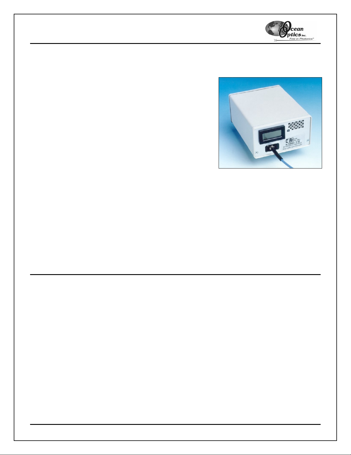
The S2000 Miniature Fiber Optic Spectrometer is available with the
TR-2 Thermoelectric Temperature Regulator, a device that stabilizes
the temperature of the optical bench, optics and CCD array in each of
up to six spectrometer channels. Over a 24-hour period, the TR-2
controls the temperature of the optical bench to +/- 0.1 °C, with
baseline and spectral stabil it y to +/-0.001 Abs or b anc e Units.
You can read the current temperature of the S2000 spectrometer and
set and store into memory the desired temperature for the S2000
(called the set-point temperature). The LED on the front of the TR-2
displays the current system status:
• If the LED is green, the temperature of the S2000 is within
• If the LED is continuously red, the temperature of the S2000 is not yet at the stored set-point temperature.
• If the LED is blinking red, then there is a system malfunction.
The TR-2 is a demand-based temperature regulator. When the semiconductor sensor indicates the temperature
has drifted from the set-point temperature more than 0.1
thermoelectric element in the correct direction (heat or cool). A series resistor limits current through the
thermoelectric element to its specified maximum. The indicator light turns red when deviation from the set-point
temperature exceeds 0.2
The TR-2 achieves temperature stability 15 °C below the ambient temperature. For example, if the ambient
temperature is 25 °C, then the minimum stable temperature that the S2000 could achieve with the TR-2 would be
approximately 10 °C. No matter what the ambient temperature is, the maximum stable temperature that the
S2000 can achieve with the TR-2 is 37 °C.
o
± 0.1
C of the stored set-point temperature.
o
C.
o
C, the unit transmits pulses of current to the
Operation Notes
1. When large changes of temperature are required, it may take up to 24 hours for the S2000 to achieve the
set-point temperature.
2. The temperature sensitivity of the S2000 is typically ± 0.05 pixels/oC. If the application requires <1 pixel
precision, then the spectrometer wavelength calibration procedure should be performed at the set-point
temperature.
3. If there is a system malfunction with the TR-2, the system will not be operable and the LED will turn red
and flash at 1-second intervals. When a system malfunction occurs, you can “reset” the TR-2 by
depressing the set-point temperature button. The following actions will result in a system malfunction:
• If the cooling fan fails
• If the temperature exceeds 37
• If you connect the A/D interface cable to the S2000 before connecting the power supply (see
Using the Correct Power-Up Sequence)
TR-2 Thermoelectric Temperature Regulator 1
o
C
Page 2

TR-2 Thermoelectric Temperature Regulator
Operation
The TR2 is a Temperature Regulator unit that stacks onto an S2000 Spectrometer. The TR2 displays two
temperature values (in
pushbutton and a toggle switch. The display can toggle between viewing the actual temperature and the set-point
temperature. With the pushbutton out, the display shows the actual temperature. With the pushbutton in, display
shows the set-point temperature. The temperature is set by a digitally controlled potentiometer with 100 set
points. The set-point is stored in a volatile memory location. To store the set point permanently, press the toggle
switch to the down position and then press the set button. This action will lock the set temperature into permanent
memory.
A standard TR2 can be adjusted between 0 °C and 37 °C. However the TR2 is only capable operating 15 °C
below the ambient temperature. At cool temperatures, you must insure that condensation does not occur
on the inside of the optical bench. By design, the maximum temperature set-point is 37 °C.
The TR2 requires a regulated +12 V power supply that delivers at least 2 amps. Poor results may be obtained if a
non-regulated power supply or a supply that cannot deliver adequate current is used. The power connection is
configured for a positive center polarity.
The TR2 indicates its status with a two color LED. The status conditions are defined as:
Green – The TR2 has reached temperature stability (within 0.1
Red – The TR2 has not reached temperature stability
Blinking Red – The TR2 is not running. Reset by pushing the pushbutton
The S2000-TR2 system operates from two power supplies; the 5V from the ADC Card and the +12V from the
external power supply. Depending on the order which power is applied, the TR2 may power up with a blinking red
LED. To clear the blinking LED press the pushbutton to reset the unit.
o
C), the set temperature and actual temperature. The TR2 has two controls, a set point
o
C)
The following sections provide instructions for using the TR-2 Thermoelectric Temperature Regulator:
Using the Correct Power-Up Sequence
You must power-up the TR-2 system in the manner listed below to ensure that the TR-2 and sampling system
operate correctly. Otherwise, the unit may malfunction (indicated by a blinking red LED).
1. Connect power to the TR-2 using a regulated +12V DC power supply that delivers at least 2 amps.
Using a non-regulated power supply or a supply that cannot deliver adequate current/voltage will result
in unreliable or inadequate temperature control.
2. Connect the A/D interface cable to the S2000. Do not connect the A/D interface cable before connecting
power to the TR-2.
3. Disconnect power by unplugging the power source. If the system goes into system malfunction mode
during normal operation, press the set-point temperature button to reset the TR-2.
TR-2 Thermoelectric Temperature Regulator 2
Page 3

TR-2 Thermoelectric Temperature Regulator
Adjusting the Set-Point Temperature
The TR-2 displays two temperature values: the actual temperature and the set-point temperature. These values
are the same when the TR-2 has been running long enough to stabilize. The actual temperature is displayed (in
degrees C) on the TR-2.
To adjust the set-point temperature:
1. Press and hold the set-point temperature button to display the set-point temperature. The factory default
set-point temperature is 20
2. Toggle the switch to change the set-point temperature. Release the set-point temperature button once
you reach the desired set-point.
3. Store the new set-point into memory. Press and hold the toggle switch down and press the settemperature button, then release the switch.
4. Verify the new set-point has been stored into permanent memory by unplugging the ADC interface cable
for approximately five seconds. Reattach the ADC cable and follow Step 1 again to display the stored setpoint.
o
C.
Specifications
TR-2 Thermoelectric Temperature Regulator Specifications
Temperature regulator type: Peltier thermoelectric dev ic e
Set-point temperature range: 15 °C below ambient to 37 °C
Set-point temperature default: User-programmable; factory-set to 20 °C
Temperature control of optical bench: To +/- 0.1 °C
Baseline and spectral stability (measured
over 24-hour period, for spectrometer only):
Effect on integration time:
Note: If the ambient temperature changes significantly (> 5 oC), the user should employ the “Correct for
Electrical Dark” feature in OOIBase32 Spectrometer Operating Software. The "Correct for Electrical Dark"
function compensates for ambient temperature changes that shift the analog signal by several counts.
This "shifting" is an electrical effect due to changing voltage references. The shifting is not optically
related. Ambient temperature changes of 5 °C typically produce a shift of the entire spectra of 5-10
counts.
+/- 0.001 Absorbance Units (AU)
Integration times >10 seconds can be achieved
without significant increase in dark spectra (if
cooled to minimum temperature only)
Pinouts
The TR2 interfaces to the S2000 using the H1 and H2 connectors. The pin-out for these signals is show below. In
addition, the TR2 has a J3 connector that communicates the various temperature signals. The J3 pinouts are
shown below.
When Multiple S2000-TR2 assemblies are stacked together, several signals in the J3 connector need to be
connected between all of the TR2 boards in the stack. The table below defines these signals. In this setup, the
display only shows the actual and set-point temperatures from a single unit. Typically, this unit is the Master
Spectrometer Channel.
TR-2 Thermoelectric Temperature Regulator 3
Page 4

TR-2 Thermoelectric Temperature Regulator
J3 Definition
PIN Signal Name Connections Description
1 N/C No Connect
2 VTEMP From one TR2 (Master)
3 Reset All Reset signal for TR2
4 VSET From one TR2 (Master)
5 Ground All +5V Ground
6 Vdisplay From one TR2 (Master) Analog Signal that is displayed. Scaling is 100mv/oC
7 Toggle Down All Clock signal to toggle the set-point down one increment
8 N/C No Connect
9 Ground All +5V Ground
10 Toggle Up All Clock signal to toggle the set-point up one increment
Analog signal of the current temperature. Scaling is
100mv/
Set-point temperature signal to be displayed when
pushbutton is depressed. Scaling is 100mv/
o
C
o
C)
S2000-H1 Header Pins (Analog) S2000-H2 Header Pins (Digital)
1 Analog Channel 0 D N/C
2 Analog Channel 1 C A/D Trigger
3 Analog Channel 2 B Software Trigger In (D3)
4 Analog Channel 3 A Trigger Mode Select (S1)
5 Analog Channel 4 1 GND
6 GND 2 +5 VDC
7 Reserved 3 F Clock
8 Analog Channel 7 4 Readout Gate
9 Analog Channel 6 5 Reserved
10 Analog Channel 5 6 Temperature (optional)
7 Read Enable
9 Single Strobe Out
10 Continuous Strobe Out
11 Integration Clock
12 Master Clock
Trigger Mode Select/Strobe Enable
8
(S0)
TR-2 Thermoelectric Temperature Regulator 4
 Loading...