

Page 1
Reflection Stage
Stage-RTL-T
Installation and Operation Manual
Document Number 000-10000-170-02-1209
Offices: Ocean Optics, Inc. World Headquarters
830 Douglas Ave., Dunedin, FL, USA 34698
Phone 727.733.2447
Fax 727.733.3962
8 a.m.– 8 p.m. (Mon-Thu), 8 a.m.– 6 p.m. (Fri) EST
Ocean Optics Mikropack
Maybachstraße 11, D-73760, Ostfildern, Germany
Phone +49 (0)711 34 16 96-0
Fax +49 (0)711 34 16 96-85
000-00000-000-02-A
E-mail: Info@OceanOptics.com (General sales inquiries)
Info@Mikropack.de (Mikropack sales inquiries)
Orders@OceanOptics.com (Questions about orders)
TechSupport@OceanOptics.com (Technical support)
Protective Eye Wear Must Be Worn
When Using This Instrument Intense Ultraviolet Radiation Present
WARNING
See Important Safety Notices inside.
Page 2

Copyright © 2009 Ocean Optics, Inc.
All rights reserved. No part of this publication may be reproduced, stored in a retrieval system, or transmitted, by any means, electronic,
mechanical, photocopying, recording, or otherwise, without written permission from Ocean Optics, Inc.
This manual is sold as part of an order and subject to the condition that it shall not, by way of trade or otherwise, be lent, re-sold, hired out or
otherwise circulated without the prior consent of Ocean Optics, Inc. in any form of binding or cover other than that in which it is published.
Trademarks
Microsoft, Windows, Windows 95, Windows 98, Windows Me, Windows NT, Windows 2000, Windows XP and Excel are either registered
trademarks or trademarks of Microsoft Corporation.
Limit of Liability
Every effort has been made to make this manual as complete and as accurate as possible, but no warranty or fitness is implied. The information
provided is on an “as is” basis. Ocean Optics, Inc. shall have neither liability nor responsibility to any person or entity with respect to any loss or
damages arising from the information contained in this manual.
Page 3

Important Safety Notices
1. Read all safety notices and operating instructions before operating this unit.
2. Inspect the item for transport damage before using it for the first time.
3. Adhere to all warning stickers on the unit and all warnings contained in this manual.
Warranty
Mikropack GmbH warrants to the original user of this instrument that it shall be free of any defects
resulting from faulty manufacture of this instrument for a period of 12 months from the original data of
shipment. There is no warranty for the bulb.
This instrument should not be used for any Clinical or Diagnostic purposes. Data generated in these
areas is not warranted in any way by Mikropack GmbH. Any defects covered by this Warranty shall be
corrected either by repair or by replacement, as determined by Mikropack GmbH.
There are no warranties that extend beyond the description herein.
This Warranty is in lieu of, and excludes, any and all other warranties or representations expressed,
implied, or statutory, including merchantability and fitness, as well as any and all other obligations or
liabilities of Mikropack GmbH including, but not limited to, special or consequential damages. No
person, firm, or corporation is authorized to assume for Mikropack GmbH. Any additional obligation or
liability not expressed provided for herein except in writing duly executed by an officer of Mikropack
GmbH:
MIKROPACK GmbH
Maybachstraße 11
D-73760 Ostfildern
Tel.: +49 (0)711 3428088 • Fax.: +49 (0)711 3428085
e-mail: info@mikropack.de
www.mikropack.de
internet:
000-10000-170-02-1209 A
Page 4

Page 5

Table of Contents
About This Manual .............................................................................................................iii
Document Purpose and Intended Audience..............................................................................iii
Document Summary..................................................................................................................iii
Product-Related Documentation ............................................................................................... iii
Upgrades ............................................................................................................................iii
Chapter 1: Introduction .......................................................................1
Overview.............................................................................................................................1
Unpacking the Stage-RTL-T ..............................................................................................2
Contents .............................................................................................................................3
Chapter 2: Set-up .................................................................................5
Overview.............................................................................................................................5
Reflection Set-up ................................................................................................................5
Parts Used .................................................................................................................................5
Reflection Measurement Set-up Procedure ..............................................................................5
Reflection Measurement of a Transparent Sample Set-up Procedure .....................................6
Upside Down Reflection Set-up .........................................................................................7
Parts Used .................................................................................................................................7
Upside Down Reflection Measurement Set-up Procedure........................................................ 7
Upside Down Reflection Measurement of a Transparent Sample Set-up Procedure............... 8
Transmission Set-up ..........................................................................................................9
Parts Used .................................................................................................................................9
Transmission Measurement Set-up Procedure......................................................................... 9
Appendix A: Specifications.................................................................11
Index ......................................................................................................13
000-10000-170-02-1209 i
Page 6

Table of Contents
ii 000-10000-170-02-1209
Page 7
About This Manual
Document Purpose and Intended Audience
This document provides you with an installation section to get your system up and running.
Document Summary
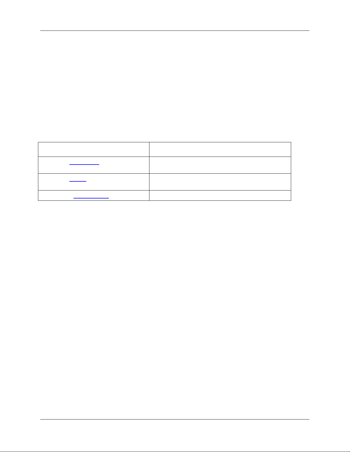
Chapter Description
Chapter 1: Introduction
Chapter 2: Set-up
Appendix A: Specifications
Contains a list of package contents and unpacking
instructions.
Contains instructions for setting up the Stage-RTL-T
for measuring reflection and transmission.
Provides physical specifications for the Stage-RTL-T.
Product-Related Documentation
You can access documentation for Ocean Optics products by visiting our website at
http://www.oceanoptics.com. Select Technical → Operating Instructions, then choose the appropriate
document from the available drop-down lists. Or, use the
of the web page.
You can also access operating instructions for Ocean Optics products on the
Resources
Engineering-level documentation is located on our website at Technical → Engineering Docs.
CD included with the system.
Search by Model Number field at the bottom
Software and Technical
Upgrades
Occasionally, you may find that you need Ocean Optics to make a change or an upgrade to your system.
To facilitate these changes, you must first contact Customer Support and obtain a Return Merchandise
Authorization (RMA) number. Please contact an Ocean Optics Application Scientist for specific
instructions when returning a product.
000-10000-170-02-1209 iii
Page 8

About This Manual
iv 000-10000-170-02-1209
Page 9

Chapter 1
Introduction
Overview
The Stage-RTL-T is a novel sampling system for analysis of substrate materials such as silicon, metals,
glass and plastics. This stage system couples to our spectrometers and light sources, and can be
configured in a variety of setups for transmission and reflection measurements.
The STAGE-RTL-T is remarkably versatile: perform reflection measurements with the probe positioned
above or below the sample (measuring from below maintains a constant distance between probe and
sample); make reflection measurements with the light trap in place; or measure transmission of samples
using two fibers.
The Stage-RTL-T consists of a variable rail attached to a base plate, with three devices that attach to the
rail with a thumbscrew. From bottom to top, these devices are a fiber holder with UV-VIS collimating
lens; a sample holder for reflection or transmission; and a light trap to mitigate the effects of back
reflection and ambient light. (Remove the light trap to access a second collimating lens.)
000-10000-170-02-1209 1
Page 10

1: Introduction
Unpacking the Stage-RTL-T
► Procedure
1. Unpack your lamp assembly carefully. Dropping this instrument can cause permanent damage.
2. Inspect the outside of the instrument and make sure that there is no damage. Do not use the
instrument if damage is present.
2 000-10000-170-02-1209
Page 11

1: Introduction
3. Use this instrument in a clean laboratory environment (see Error! Reference source not found.).
Contents
Your Stage-RTL-T package should contain the following:
One (1) Base plate
One (1) Rail
One (1) Light trap
One (1) Sample holder
Two (2) Fiber holders
Two (2) 74-UV collimating lenses
Two (2) socket wrenches
000-10000-170-02-1209 3
Page 12

1: Introduction
4 000-10000-170-02-1209
Page 13

Overview
The Stage-RTL-T is very versatile and can be set up to measure the following:
Reflection
Reflection (upside down)
Transmission
Reflection Set-up
Chapter 2
Set-up
Use the Stage-RTL-T to measure reflection and reflection of a transparent sample.
Parts Used
Fiber holder
Sample holder (optional)
Light trap (optional)
Reflection Measurement Set-up Procedure
► Procedure
1. Affix the reflection probe in the fiber holder.
2. Adjust height of the fiber holder.
3. Place your sample on the sample holder or on the base plate.
4. Start acquisition.
000-10000-170-02-1209 5
Page 14

2: Set-up
5. Readjust height of the fiber holder / reflection probe until you get the maximum signal.
6. Start your measurements.
Reflection Measurement of a Transparent Sample Set-up
Procedure
► Procedure
1. Attach the light trap to the rail (upside down).
2. Attach the sample holder above the light trap to the rail.
6 000-10000-170-02-1209
Page 15

A: Specifications
3. Affix the reflection probe in the fiber holder.
4. Adjust height of the fiber holder.
5. Place your sample on the sample holder or on the base plate.
6. Start acquisition.
7. Readjust height of the fiber holder / reflection probe until you get the maximum signal.
8. Start your measurements.
Upside Down Reflection Set-up
Setting up the reflection measurement upside down has the advantage that the distance between the fiber
and the surface is constant; sample probe thickness is no longer an issue. Use the Stage-RTL-T to
measure reflection and reflection of a transparent sample.
Parts Used
Fiber holder
Sample holder
Light trap
Upside Down Reflection Measurement Set-up Procedure
► Procedure
1. Affix the reflection probe in the fiber holder.
2. Adjust height of the fiber holder so that the fiber bend radius is large enough.
3. Attach the sample holder to the rail above the fiber holder.
4. Place your sample upside down on the sample holder.
5. Start acquisition.
6. Readjust height of the reflection probe until you get the maximum signal. Make sure that the
reflection probe does not touch the sample.
7. Start your measurements.
000-10000-170-02-1209 7
Page 16

2: Set-up
Upside Down Reflection Measurement of a Transparent
Sample Set-up Procedure
► Procedure
1. Affix the reflection probe in the fiber holder.
2. Adjust height of the fiber holder so that the fiber bend radius is large enough.
3. Attach the sample holder to the rail above the fiber holder.
4. Place your sample upside down on the sample holder.
8 000-10000-170-02-1209
Page 17

5. Attach the light trap to the rail. Adjust the position of the light trap so that no external light
reaches the reflection probe.
6. Start acquisition.
7. Readjust height of the reflection probe until you get the maximum signal. Make sure that the
reflection probe does not touch the sample.
8. Start your measurements.
Transmission Set-up
Use the Stage-RTL-T to measure transmission of a sample.
Parts Used
Two (2) 74UV collimating lenses
Two (2) fiber holders
A: Specifications
Sample holder
Transmission Measurement Set-up Procedure
► Procedure
1. Unscrew the light trap of fiber holder 1.
2. Unscrew the reflection probe holder of fiber holder 2.
3. Screw the 74UV into the fiber holders.
4. Attach the lower fiber holder to the rail. Adjust height so that the fiber bend radius is sufficient.
5. Attach the sample holder to the rail above fibe rholder 1.
6. Attach fiber holder 2 to the rail above the sample holder.
7. Connect the fibers to the fiber holders.
8. Adjust position of the upper fiber holder so that there is enough room for the sample.
9. Adjust the focus of the 74UV collimating lens.
10. Start measuring.
000-10000-170-02-1209 9
Page 18

2: Set-up
10 000-10000-170-02-1209
Page 19

Specifications
Specification Value
Dimensions
Base
Sample Area
Weight 4.5 kg
Height Rail height adjustable to 400 mm
206.3 mm
152.4 mm diameter (sample holder)
Appendix A
000-10000-170-02-1209 11
Page 20

A: Specifications
12 000-10000-170-02-1209
Page 21

Index
D
document
audience, iii
purpose, iii
summary, iii
P
package contents, 3
product-related documentation, iii
R
reflection
set-up, 5
transparent sample set-up, 6
upside down set-up, 7
upside down set-up of transparent sample, 8
S
safety notices, A
set-up
reflection, 5
reflection of transparent sample, 6
transmission, 9
upside down reflection, 7
upside down reflection of transparent sample,
8
specifications, 11
T
transmission
set-up, 9
U
unpacking procedure, 2
upgrades, iii
W
warranty, A
000-10000-170-02-1209 13
Page 22

A: Specifications
14 000-10000-170-02-1209
 Loading...