

Page 1

NIR Near Infrared
Fiber Optic Spectrometers
Installation and Operation Manual
Document Number 197-00000-512-02-0707
Offices:
E-mail: Info@OceanOptics.com (General sales inquiries)
Ocean Optics, Inc. World Headquarters
830 Douglas Ave., Dunedin, FL, USA 34698
Phone 727.733.2447
Fax 727.733.3962
8 a.m.– 8 p.m. (Mon-Thu), 8 a.m.– 6 p.m. (Fri) EST
Orders@OceanOptics.com (Questions about orders)
TechSupport@OceanOptics.com (Technical support)
Page 2

Additional
Offices:
Ocean Optics Asia
666 Gubei Road, Kirin Tower, Suite 601B, Changning District, Shanghai,
PRC. 200336
Phone 86.21.5206.8686
Fax 86.21.5206.8686
E-Mail Sun.Ling@OceanOptics.com
Ocean Optics B.V. (Europe)
Geograaf 24, 6921 EW DUIVEN, The Netherlands
Phone 31-(0)26-3190500
Fax 31-(0)26-3190505
E -Mail Info@OceanOpticsBV.com
Copyright © 2001-2007 Ocean Optics, Inc.
All rights reserved. No part of this publication may be reproduced, stored in a retrieval system, or transmitted, by any means, electronic,
mechanical, photocopying, recording, or otherwise, without written permission from Ocean Optics, Inc.
This manual is sold as part of an order and subject to the condition that it shall not, by way of trade or otherwise, be lent, re-sold, hired out or
otherwise circulated without the prior consent of Ocean Optics, Inc. in any form of binding or cover other than that in which it is published.
Trademarks
All products and services herein are the trademarks, service marks, registered trademarks or registered service marks of their respective owners.
Limit of Liability
Every effort has been made to make this manual as complete and as accurate as possible, but no warranty or fitness is implied. The information
provided is on an “as is” basis. Ocean Optics, Inc. shall have neither liability nor responsibility to any person or entity with respect to any loss or
damages arising from the information contained in this manual.
Page 3

Table of Contents
About This Manual .......................................................................................................... iii
Document Purpose and Intended Audience.............................................................................. iii
What’s New in this Document ................................................................................................... iii
Document Summary.................................................................................................................. iii
Product-Related Documentation ............................................................................................... iv
Upgrades......................................................................................................................... iv
Service ............................................................................................................................ iv
Chapter 1: Introduction ......................................................................1
Product Description ......................................................................................................... 1
About the Modular Approach..................................................................................................... 2
Interface Options ............................................................................................................. 3
Items Included with Shipment ......................................................................................... 3
Chapter 2: Installing the NIR Spectrometer......................................5
Overview ......................................................................................................................... 5
NIR Spectrometer Installation.......................................................................................... 5
USB Mode ................................................................................................................................. 5
Serial Port Mode........................................................................................................................ 6
Configuring the NIR Spectrometer .................................................................................. 7
Configuring the NIR Spectrometer in SpectraSuite................................................................... 7
Configuring the NIR Spectrometer in OOIBase32 .................................................................... 7
Connect Spectroscopic Accessories ............................................................................... 7
External Triggering Options............................................................................................. 7
NIR Controls....................................................................................................................8
SpectraSuite NIR Spectrometer Features................................................................................. 8
NIR Toolbar in OOIBase32........................................................................................................9
Chapter 3: Troubleshooting ...............................................................11
Overview ......................................................................................................................... 11
NIR Spectrometer Connected to Computer Prior to Operating Software ........................ 11
Windows Operating Systems ....................................................................................................11
Remove the Unknown Device from Windows Device Manager................................................ 12
197-00000-512-02-0707 i
Page 4

Table of Contents
Remove Improperly Installed Files ............................................................................................ 12
Mac Operating Systems ............................................................................................................ 13
Linux Operating Systems ..........................................................................................................13
Troubleshooting the Serial Port Configuration................................................................. 13
Old Version of OOIBase32 Installed ............................................................................... 14
Appendix A: Calibrating the Wavelength of the NIR Spectrometer15
About Wavelength Calibration......................................................................................... 15
Calibrating the Spectrometer........................................................................................... 15
Preparing for Calibration............................................................................................................ 15
Calibrating the Wavelength of the Spectrometer............................................................. 16
Saving the New Calibration Coefficients: USB Mode ...................................................... 18
Saving the New Calibration Coefficients: Serial Mode .................................................... 19
Appendix B: Specifications................................................................21
How the Spectrometer Works.......................................................................................... 21
NIR Spectrometer Component Table ........................................................................................ 21
NIR Detector Specifications....................................................................................................... 22
NIR Spectrometer – Slit Size vs. Resolution and Throughput......................................... 23
NIR Spectrometer Specifications..................................................................................... 23
9-pin RS-232 Serial Port Pinout ................................................................................................ 25
9-pin RS-232 Serial Port Connector – Pin Definitions............................................................... 25
15-pin Accessory Connector Pinout .......................................................................................... 26
15-pin Accessory Connector – Pin Definitions .......................................................................... 26
LED Information .............................................................................................................. 26
Appendix C: NIR256-2.5µm Sensitivity .............................................27
Index.....................................................................................................29
ii 197-00000-512-02-0707
Page 5
About This Manual
Document Purpose and Intended Audience
This document provides you with instructions to get your system up and running. In addition to the NIR
Spectrometer installation and operation instructions, this manual also includes information for locating
the SpectraSuite installation instructions (see Product-Related Documentation
What’s New in this Document
This version of the NIR Near Infrared Fiber Optics Spectrometers Installation and Operation Manual
adds SpectraSuite information and updates the contact list. It also includes information about our service
packages available for NIR spectrometers.
below).
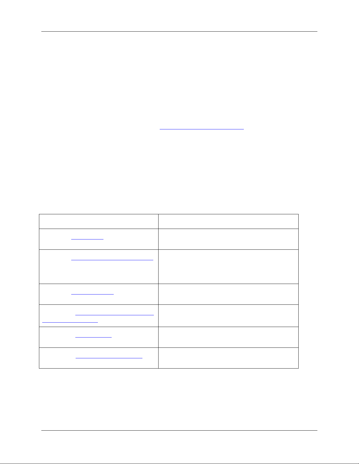
Document Summary
Chapter Description
Chapter 1: Introduction
Chapter 2: Installing the NIR Spectrometer
Chapter 3: Troubleshooting
Appendix A: Calibrating the Wavelength of
the NIR Spectrometer
Appendix B: Specifications
Appendix C: NIR256-2.5µm Sensitivity
Introduces the product features. Also contains a list
of items included in the shipment.
Contains information for installing and configuring
your NIR Spectrometer. These instructions include
information on using your NIR Spectrometer with
the spectrometer operating software.
Contains typical problems and suggested
resolutions.
Contains instructions for calibrating your NIR
Spectrometer.
Contains technical specifications for the NIR
Spectrometer and the NIR Detector.
Provides some additional sensitivity specifications
for the NIR256-2.5 Spectrometer.
197-00000-512-02-0707 iii
Page 6

1: Introduction
Product-Related Documentation
You can access documentation for Ocean Optics products by visiting our website at
http://www.oceanoptics.com. Select Technical → Operating Instructions, then choose the appropriate
document from the available drop-down lists. Or, use the Search by Model Number field at the bottom
of the web page.
• Detailed instructions for SpectraSuite Spectrometer Operating Software are located at:
http://www.oceanoptics.com/technical/SpectraSuite.pdf.
• Detailed instructions for the OOIBase32 Spectrometer Operating Software are located at:
http://www.oceanoptics.com/technical/ooibase32.pdf
You can also access operating instructions for Ocean Optics products on the Software and Technical
Resources CD included with the system.
Engineering-level documentation is located on our website at Technical → Engineering Docs.
Upgrades
Occasionally, you may find that you need Ocean Optics to make a change or an upgrade to your system.
To facilitate these changes, you must first contact Customer Support and obtain a Return Merchandise
Authorization (RMA) number. Please contact Ocean Optics for specific instructions when returning a
product.
Service
Our Total Technical Service protection plans protect your spectrometer for one year for any contingency -
- no matter what the circumstances, including total loss. Under these plans, Ocean Optics will repair or
replace your instrument with no deductible or any other out-of-pocket expense required from you. NIR
service plans include the following:
• TTS-NIR: Protects your Ocean Optics NIR spectrometer for any contingency for 1 year.
Provides for full spectrometer replacement, if necessary. Limited to 1 full replacement per year.
• TTS-NIR-E: This special plan for Ocean Optics NIR spectrometers not previously covered
protects for any contingency for 1 year. Provides for full spectrometer replacement, if necessary.
Limited to 1 full replacement per year. This coverage starts 30 days after purchasing the plan.
iv 197-00000-512-02-0707
Page 7
Chapter 1
Introduction
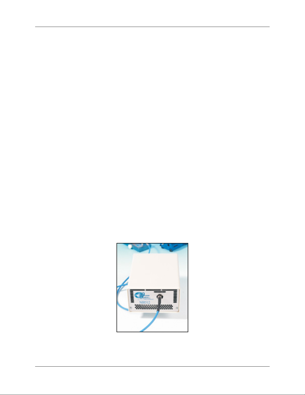
Product Description
The NIR (Near Infrared) Fiber Optic Spectrometer connects to a notebook or desktop PC via a USB port.
It requires an external +5VDC power supply (USB-CBL-PS) to power the spectrometer’s highperformance InGaAs array detector. The NIR Spectrometer and the 16-bit A/D converter share a single
housing, forming a small-footprint plug-and-play system.
The NIR Spectrometer can connect via the USB port to any PC that uses a Windows 98/Me/2000/XP
operating system and has spectrometer operating software installed and configured for use with your NIR
Spectrometer. Furthermore, the NIR Spectrometer has a serial port for interfacing to PCs, PLCs, and other
devices that support the RS-232 communication protocol.
An EEPROM memory chip in each NIR Spectrometer contains wavelength calibration coefficients,
linearity coefficients, and the serial number unique to each spectrometer. Ocean Optics OOIBase32 or
SpectraSuite spectrometer operating software reads these values from the spectrometer, which allows
“hot-swapping” of spectrometers among multiple PCs.
As with all other Ocean Optics user-configured spectrometers, you can choose from six slit sizes and
hundreds of fiber optic accessories (such as light sources, probes, and optical fibers) to create the system
just right for your application.
197-00000-512-02-0707 1
Page 8

1: Introduction
About the Modular Approach
Ocean Optics fiber optic spectrometer systems are based on low-cost, modular data acquisition principles.
A typical NIR Spectrometer system contains four basic elements:
• The NIR Spectrometer
• The Ocean Optics spectrometer operating software
• A light (excitation source)
• A variety of sampling optics (depending on application need)
The light (excitation source) sends light through an optical fiber to the sample. The light interacts with the
sample, and the results of that interaction are collected and transmitted through another optical fiber to the
spectrometer. The spectrometer measures the amount of light and transforms the data collected by the
spectrometer into digital information. Finally, the spectrometer passes that information to the operating
software.
Software
SpectraSuite is the latest generation of operating software for all Ocean Optics spectrometers. It is a
completely modular, Java-based spectroscopy software platform that operates on Windows, Macintosh
and Linux operating systems. The software can control any Ocean Optics USB spectrometer and device,
as well as any other manufacturer’s USB instrumentation using the appropriate drivers.
SpectraSuite is a user-customizable, advanced acquisition and display program that provides a real-time
interface to a variety of signal-processing functions. With SpectraSuite, you have the ability to perform
spectroscopic measurements (such as absorbance, reflectance, and emission), control all system
parameters, collect and display data in real time, and perform reference monitoring and time acquisition
experiments. Consult the SpectraSuite manual for hardware requirements when using SpectraSuite (see
Product-Related Documentation
OOIBase32 software has been discontinued, but still functions with the NIR spectrometers. Consult the
OOIBase32 manual for hardware requirements when using OOIBase32 (see Product-Related
Documentation
).
).
Accessories
Ocean Optics also offers a complete line of spectroscopic accessories to use with the NIR Spectrometer.
Most spectroscopic accessories have SMA connectors for application flexibility. Thus, changing the
sampling system is as easy as unscrewing a connector and adding a new component or accessory. A
partial list of Ocean Optics spectroscopic accessories includes light sources, sampling holders, filter
holders, flow cells, fiber optic probes and sensors, collimating lenses, attenuators, diffuse reflectance
standards, integrating spheres and an extensive line of optical fibers.
This modular approach, where components are easily mixed and matched, offers remarkable applications
flexibility. You can select from hundreds of products to create distinctive systems for an almost endless
variety of optical-sensing applications.
2 197-00000-512-02-0707
Page 9
1: Introduction
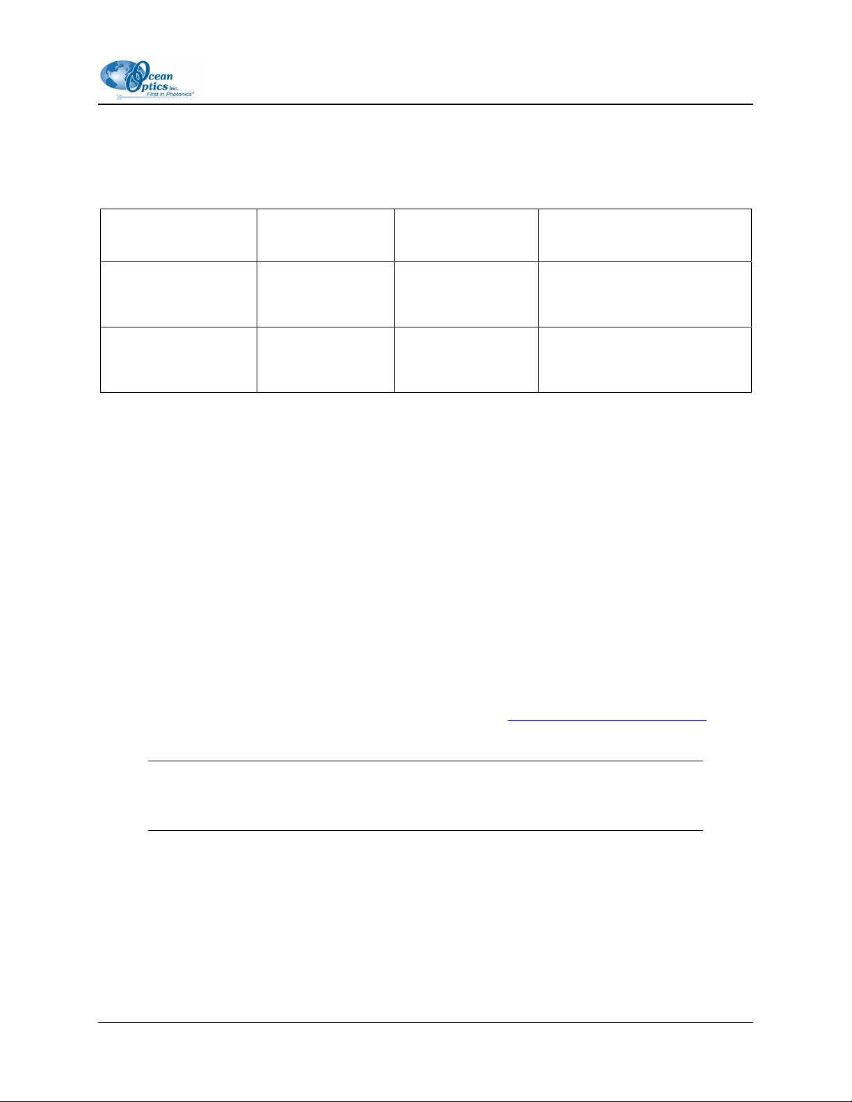
Interface Options
Because the NIR Spectrometer has both a USB and a serial port, you can connect the NIR Spectrometer
to a desktop or notebook PC via a USB port or to a desktop or notebook PC via a serial port.
Computer Interface
Desktop or Notebook
PC via USB Port
Desktop or Notebook
PC via Serial Port
Operating System
Requirements
Windows 98/Me/
2000/XP
Any 32-bit
Windows operating
system
Cable Needed Description of Cable
USB-CBL-1
(included)
ADC-USB-SER
(not included)
Cable connects from USB port
on NIR Spectrometer to USB
port on desktop or notebook PC
Cable connects from serial port
on NIR Spectrometer to serial
port on desktop or notebook PC
Items Included with Shipment
Important information and documentation accompany your NIR Spectrometer upon shipment. This
includes:
Packing List – The packing list is located inside a plastic bag attached to the outside of the
shipment box (the invoice is mailed separately). The items listed on the packing slip include all of
the components in the order, including customized items installed in the spectrometer, such as the
slit. The packing list also includes important information, such as the shipping and billing
addresses, as well as any components on back order.
Wavelength Calibration Data Sheet – Each spectrometer is shipped with a Wavelength
Calibration Data Sheet that contains information unique to your spectrometer. SpectraSuite
Operating Software reads this calibration data from your spectrometer when it interfaces to a PC
via the USB port. Any other interface requires that you manually enter the calibration data in
OOIBase32 (select Spectrometer | Configure | Wavelength Calibration tab). See the
OOIBase32 documentation for more information (refer to Product-Related Documentation
instructions on accessing OOIBase32 documentation).
for
Note
Please save the Wavelength Calibration Data Sheet for future reference.
Software and Resources Library CD – Each spectrometer order comes with Ocean Optics’
Software and Resources Library CD. This disc contains all Ocean Optics software and manuals
for software operation, spectrometers, and spectroscopic accessories. Documentation is provided
in Portable Document Format (PDF). You need Adobe Acrobat Reader version 6.0 or higher to
view these files. Adobe Acrobat Reader is included on the CD.
Passwords for software applications can be found on the back of the Software and Resources
Library CD package.
197-00000-512-02-0707 3
Page 10

1: Introduction
4 197-00000-512-02-0707
Page 11

Chapter 2
Installing the NIR Spectrometer
Overview
You must install the operating software application prior to connecting the NIR Spectrometer to the PC.
The Ocean Optics spectrometer operating software installs the drivers required for NIR Spectrometer
installation. If you do not install the software first, the system will not properly recognize the NIR
Spectrometer.
If you have already connected the NIR Spectrometer to the PC prior to installing the software, consult
Chapter 3: Troubleshooting
for information on correcting a corrupt NIR Spectrometer installation.
Once you have properly installed the spectrometer, refer to either the SpectraSuite or OOIBase32
operating instructions for information on taking measurements.
NIR Spectrometer Installation
This section contains instructions for connecting the NIR Spectrometer via both USB and serial modes.
USB Mode
Follow the steps in this section to interface the NIR Spectrometer via the USB port to a desktop or
notebook PC.
To connect the NIR Spectrometer to a PC via the USB port, the PC must be running the Windows
98/ME/2000/XP operating system.
Procedure
►
1. Install spectrometer operating software on the destination computer, and then reboot the
system.
2. Plug the +5VDC wall adapter (USB-CBL-PS) into an electrical outlet, then connect the
power cord to the 2.5 mm power jack (older versions may have a 1.3 mm power jack) on
the rear of the NIR Spectrometer.
3. Locate the USB cable (USB-CBL-1) that came with the NIR Spectrometer.
197-00000-512-02-0707 5
Page 12

2: Installation
4. Insert the square end of the cable into the rear of the NIR Spectrometer, and then insert
the rectangular end into the USB port of the computer.
If the software was installed prior to connecting the NIR Spectrometer, the Add New Hardware Wizard
appears and installs the NIR Spectrometer drivers. If the drivers do not successfully install, or if you
connected the NIR Spectrometer to the computer before installing the software, consult Chapter 4:
Troubleshooting
.
Note
Windows XP users may encounter a Hardware Installation warning window regarding
Windows XP driver testing. Click the Continue Installation button at this screen, as this
is an expected warning.
Serial Port Mode
To use the serial port capacity of the NIR Spectrometer, the PC must be running a 32-bit version of the
Windows operating system.
►
Procedure
Follow the steps below to connect the NIR Spectrometer to the PC via serial port:
1. Connect one end of the serial cable to the RS-232 connector on the rear of the NIR Spectrometer,
and then connect the other end to a serial port on the PC.
2. Note the serial port number (also called COM Port) on the PC to which the NIR Spectrometer is
connected (some PCs may not have numbered ports).
3. Plug the +5VDC wall adapter (USB-CBL-PS) into an electrical outlet, then connect the power
cord to the 2.5 mm power jack (older versions may have a 1.3 mm power jack) on the rear of the
NIR Spectrometer.
The NIR Spectrometer is now connected to the PC’s serial port.
Note
Connecting the spectrometer to the PC’s serial port requires that you manually enter the
calibration coefficients from the Wavelength Calibration Data Sheet into OOIBase32
software (select Spectrometer | Configure | Wavelength Calibration tab). See the
OOIBase32 documentation for more information (refer to Product-Related
Documentation
for instructions on accessing OOIBase32 documentation).
6 197-00000-512-02-0707
Page 13

2: Installation
Configuring the NIR Spectrometer
The NIR spectrometer can be used with either SpectraSuite or OOIBase32 software when connected to
the USB port. The configuration process differs, depending on whether you are running SpectraSuite or
OOIBase32 software.
Configuring the NIR Spectrometer in SpectraSuite
If you have followed the previous steps and started SpectraSuite, the spectrometer is already acquiring
data. Even with no light in the spectrometer, there should be a dynamic trace displayed in the bottom of
the graph. If you allow light into the spectrometer, the graph trace should rise with increasing light
intensity. This means the software and hardware are correctly installed.
Note the spectrometer(s) that you have installed are listed in the Data Sources pane.
Configuring the NIR Spectrometer in OOIBase32
Once you install the spectrometer, you must configure OOIBase32’s Configure Spectrometer options so
that OOIBase32 recognizes the NIR Spectrometer. Consult the OOIBase32 Spectrometer Operating
Software Operating Instructions for detailed instructions on configuring the spectrometer in OOIBase32
(see Product-Related Documentation
).
Connect Spectroscopic Accessories
To find operating instructions on NIR Spectrometer-compatible products such as light sources, sampling
chambers, probes, fibers or any other Ocean Optics spectroscopic accessories, check the Software and
Technical Resources CD or the Ocean Optics website at:
http://www.oceanoptics.com/Technical/OperatingInstructions.asp.
Chapter 1: Introduction contains a list of NIR Spectrometer-compatible products. You can find
information related to these products on
http://www.oceanoptics.com/.
External Triggering Options
You can trigger the NIR Spectrometer using the External Software Triggering option through the 15-pin
accessory connector on the spectrometer. Only the External Software Trigger mode is available with the
NIR Spectrometer.
The External Triggering Options document contains instructions on configuring External Triggering with
the NIR Spectrometer. The External Triggering Options document is located at the following web site:
http://www.oceanoptics.com/technical/externaltriggering.PDF
197-00000-512-02-0707 7
Page 14

2: Installation
If you do not have web access, you can retrieve this document from the Software and Technical
Resources CD included with your spectrometer shipment.
NIR Controls
There are a number of controls for the NIR Spectrometer that are available in through the spectrometer
operating software. The software differs as to where these controls are located.
SpectraSuite NIR Spectrometer Features
Select Spectrometer | Spectrometer Features, then select the TEC tab to display the NIR Spectrometer
controls.
Control Description
Enable ThermoElectric Control
Detector Set Point Enter the target temperature of the NIR Spectrometer detector as follows:
Detector
temperature
8 197-00000-512-02-0707
Check this box to enable (recommended setting for laboratory conditions) or
uncheck to disable the thermoelectric cooler.
• NIR512: Minimum is –10 ºC, Recommended is –5 ºC
• NIR256: Minimum is –15 ºC, Recommended is –10 ºC
The TEC and fans will operate until the detector reaches this temperature.
Displays the current temperature of the detector in the NIR Spectrometer.
Page 15

2: Installation
Control Description
Enable Periodic
Update
Update Interval If you enabled periodic updates, enter the interval period (in seconds).
Show in Status Bar Check this box to display the detector temperature in the status bar.
Check this box to enable periodic update of the NIR detector temperature
controls.
NIR Toolbar in OOIBase32
The NIR toolbar in OOIBase32 allows you to control a variety of options on the NIR Spectrometer. These
options are also applicable to the NIR256.
Note
If the NIR512 Toolbar in your version of OOIBase32 does not have the options listed
below, you should upgrade your version of OOIBase32 to the latest release.
Visit
http://www.oceanoptics.com/technical/softwaredownloads.asp to obtain the
latest software version.
Control Description
TEC On Check this box to enable (recommended setting for laboratory conditions) or
uncheck to disable the thermoelectric cooler.
Det. Temp. Set Point Enter the target temperature of the NIR Spectrometer detector as follows:
• NIR512: Minimum is –10 ºC, Recommended is –5 ºC
• NIR256: Minimum is –15 ºC, Recommended is –10 ºC
The TEC and fans will operate until the detector reaches this temperature.
Apply Click this button to apply the changes made in this toolbar to the NIR
Spectrometer.
Current Det. Temp. Displays the current temperature of the detector in the NIR Spectrometer.
197-00000-512-02-0707 9
Page 16

2: Installation
10 197-00000-512-02-0707
Page 17

Chapter 3
Troubleshooting
Overview
The following sections contain information on troubleshooting issues you may encounter when using the
NIR Spectrometer.
NIR Spectrometer Connected to Computer Prior
to Operating Software
Windows Operating Systems
If you connected your NIR Spectrometer to the computer prior to installing your Ocean Optics software
application (SpectraSuite or OOIBase32), you may encounter installation issues that you must correct
before your Ocean Optics device will operate properly.
Follow the applicable steps below to remove the incorrectly installed device, device driver, and
installation files.
Note
If these procedures do not correct your device driver problem, you must obtain the
Correcting Device Driver Issues document from the Ocean Optics website:
http://www.oceanoptics.com/technical/engineering/correctingdevicedriverissues.pdf.
197-00000-512-02-0707 11
Page 18

3:Troubleshooting
Remove the Unknown Device from Windows Device Manager
► Procedure
1. Open Windows Device Manager. Consult the Windows operating instructions for your computer
for directions, if needed.
2. Locate the Other Devices option and expand the Other Devices selection by clicking on the "+"
sign to the immediate left.
Note
Improperly installed USB devices can also appear under the Universal Serial Bus
Controller option. Be sure to check this location if you cannot locate the unknown device.
3. Locate the unknown device (marked with a large question mark). Right-click on the Unknown
Device listing and select the Uninstall or Remove option.
4. Click the OK button to continue. A warning box appears confirming the removal of the Unknown
Device. Click the OK button to confirm the device removal.
5. Disconnect the NIR Spectrometer from your computer.
6. Locate the section in this chapter that is appropriate to your operating system and perform the
steps in the following Remove Improperly Installed Files
section.
Remove Improperly Installed Files
► Procedure
1. Open Windows Explorer.
2. Navigate to the Windows | INF directory.
Note
If the INF directory is not visible, you must disable the Hide System Files and Folders
and Hide File Extensions for Known File Types options in Windows Folder Options.
Access Windows Folder Options from Windows Explorer, under the Tools | Folder
Options menu selection.
12 197-00000-512-02-0707
Page 19

3: Troubleshooting
3. Delete the OOI_USB.INF in the INF directory. If your computer is running either the Windows
2000 or XP operating system, you must also delete the OOI_USB.PNF file in the INF directory.
4. Navigate to the Windows | System32 | Drivers directory.
5. Delete the EZUSB.SYS file.
6. Reinstall your Ocean Optics application and reboot the system when prompted.
7. Plug in the USB device.
The system is now able to locate and install the correct drivers for the USB device.
Mac Operating Systems
Since there are no device files for the NIR Spectrometer in a Mac operating system, you should not
encounter any problems if you installed the spectrometer before the SpectraSuite software.
Linux Operating Systems
For Linux operating systems, all you need to do is install the SpectraSuite software, then unplug and
replug in the spectrometer. Technically, the driver files for Linux simply give nonprivileged users
permission to use newly connected hardware. There isn’t any long-term harm to plugging in the device
before installing the software.
Troubleshooting the Serial Port Configuration
Occasionally, you may encounter problems with the serial port connection and/or software. Perform the
following procedure to troubleshoot the serial port connection.
►
Procedure
1. Cycle the power on the NIR Spectrometer and restart the OOIBase32 software. This ensures that
the software and the hardware synchronize properly.
2. Determine the serial port (COM port) number:
Operating System Instructions
1. Right-click on My Computer
Windows
95/98/ME/XP
197-00000-512-02-0707 13
2. Select Properties
3. Click the Device Manager tab
Page 20

3:Troubleshooting
Operating System Instructions
1. Select Start | Settings | Control Panel | System
Windows 2000
Windows NT
3. Double-click on the Ports (COM & LPT) option to display COM port numbers. Ensure that no
warning icon appears next to the NIR Spectrometer’s COM port.
4. Verify that the NIR Spectrometer’s COM port is active. If the ports on the PC are not labeled and
you do not know the COM port number, use trial-and-error to find the correct COM port. Open
OOIBase32 and view the displayed graph. If the correct COM port is selected, you will see a
dynamic trace responding to light near the bottom of the graph. If the correct COM port is not
selected, you will see a straight line at zero counts.
5. Disable virus protection to ensure timely and complete data transfer (optional – some computers
require this step).
2. Select the Hardware tab
3. Click the Device Manager button.
Select Start | Programs | Administrative Tools (common) NT
Diagnostics
Old Version of OOIBase32 Installed
If the PC to be used to interface to your NIR Spectrometer already has an older version of OOIBase32
software installed, you must install the latest version of OOIBase32. You can download the latest version
of OOIBase32 from the Software and Technical Resources CD or from the Ocean Optics website at
www.oceanoptics.com/technical/softwaredownloads.asp.
http://
You do not need to uninstall previous versions of OOIBase32 when upgrading to the latest version.
14 197-00000-512-02-0707
Page 21

Appendix A
Calibrating the Wavelength of
the NIR Spectrometer
This Appendix describes how to calibrate the wavelength of your spectrometer. Though each
spectrometer is calibrated before it leaves Ocean Optics, the wavelength for all spectrometers will drift
slightly as a function of time and environmental conditions.
About Wavelength Calibration
You are going to be solving the following equation, which shows that the relationship between pixel
number and wavelength is a third-order polynomial:
λ
= I + C1 p + C2 p2 + C3 p
p
Where:
λ
= the wavelength of pixel p
I = the wavelength of pixel 0
= the first coefficient (nm/pixel)
C
1
= the second coefficient (nm/pixel2)
C
2
= the third coefficient (nm/pixel3)
C
3
You will be calculating the value for I and the three Cs.
3
Calibrating the Spectrometer
Preparing for Calibration
To recalibrate the wavelength of your spectrometer, you will need the following:
197-00000-512-02-0707 15
Page 22

A: Calibrating the Wavelength of the Spectrometer
• A light source capable of producing spectral lines.
Ocean Optics’ AR-1 Argon lamp or HG-1 Mercury-Argon lamp are ideal for this purpose. If you
do not have an AR-1 or HG-1, you will need a spectral line source that produces several (at least
4-6) spectral lines in the wavelength region of your spectrometer.
• The NIR Spectrometer.
• An optical fiber (for spectrometers without a built-in slit, a 50-
• A spreadsheet program (Excel or Quattro Pro, for example) or a calculator that performs third-
order linear regressions.
• If you are using Microsoft Excel, choose Tools | Add-Ins and check AnalysisToolPak and
AnalysisTookPak-VBA.
µm fiber works best).
Calibrating the Wavelength of the Spectrometer
► Procedure
Perform the steps below to calibrate the wavelength of the spectrometer:
1. Place OOIBase32 into Scope mode and take a spectrum of your light source. Adjust the
integration time (or the A/D conversion frequency) until there are several peaks on the screen that
are not off-scale.
2. Move the cursor to one of the peaks and position the cursor so that it is at the point of maximum
intensity.
3. Record the pixel number that is displayed in the status bar or legend (located beneath the graph).
Repeat this step for all of the peaks in your spectrum.
4. Use the spreadsheet program or calculator to create a table like the one shown in the following
figure. In the first column, place the exact or true wavelength of the spectral lines that you used.
In the second column of this worksheet, place the observed pixel number. In the third column,
calculate the pixel number squared, and in the fourth column, calculate the pixel number cubed.
16 197-00000-512-02-0707
Page 23

A: Calibrating the Wavelength of the NIR Spectrometer
Independent Dependent Values computed from
Variable Variables the regression output
True Wavelength (nm) Pixel # Pixel # 2 Pixel #
253.65
296.73
302.15
313.16
334.15
365.02
404.66
407.78
435.84
546.07
576.96
579.07
696.54
706.72
727.29
738.40
751.47
175
296
312
342
402
490
604
613
694
1022
1116
1122
1491
1523
1590
1627
1669
30625
87616
97344
116964
161604
240100
364816
375769
481636
1044484
1245456
1258884
2223081
2319529
2528100
2647129
2785561
1067462648
1389928896
1412467848
3314613771
3532642667
4019679000
4306878883
4649101309
3
5359375
25934336
30371328
40001688
64964808
117649000
220348864
230346397
334255384
Predicted
Wavelength
253.56
296.72
302.40
313.02
334.19
365.05
404.67
407.78
435.65
546.13
577.05
579.01
696.70
706.62
727.24
738.53
751.27
Difference
0.09
0.01
-0.25
0.13
-0.05
-0.04
-0.01
0.00
0.19
-0.06
-0.09
0.06
-0.15
0.10
0.06
-0.13
0.19
5. Use your spreadsheet or calculator to calculate the wavelength calibration coefficients. In your
spreadsheet program, find the functions to perform linear regressions.
• If using Quattro Pro, look under Tools | Advanced Math
• If using Excel, look under Analysis ToolPak
6. Select the true wavelength as the dependent variable (Y). Select the pixel number, pixel number
squared, and the pixel number cubed as the independent variables (X). After you execute the
regression, an output similar to the one shown below is obtained.
Regression Statistics
Multiple R 0.999999831
R Square 0.999999663
R Squared
Adjusted R Square 0.999999607
Standard Error 0.125540214
Observations 22
intercept
Coefficients Standard Error
Intercept 190.473993 0.369047536 first coefficient
X Variable 1 0.36263983 0.001684745
X Variable 2 -1.174416E-05 8.35279E-07
X Variable 3 -2.523787E-09 2.656608E-10
third coefficient
The numbers of importance are indicated in the above figure.
second coefficient
197-00000-512-02-0707 17
Page 24

A: Calibrating the Wavelength of the Spectrometer
7. Record the Intercept as well as the First, Second, and Third Coefficients. Also, look at the value
for R squared. It should be very close to one. If it is not, you have probably assigned one of your
wavelengths incorrectly. Keep these values at hand.
Saving the New Calibration Coefficients: USB Mode
Wavelength calibration coefficients unique to each NIR Spectrometer are programmed into an EEPROM
memory chip on the NIR Spectrometer.
You can save over old calibration coefficients with new ones and the spectrometer operating software can
read these coefficients, but only if you are using the NIR Spectrometer via the USB port. If you are using
the NIR Spectrometer via the serial port, see the Saving the New Calibration Coefficients: Serial Mode
section later in this Appendix.
►
Procedure
To Save Wavelength Calibration Coefficients Using the USB Mode
1. Ensure that the NIR Spectrometer is connected to the PC and that no other applications are
running.
2. Point your browser to
down to Microcode. Double-click on USB EEPROM Programmer.
3. Save the setup file to your computer.
4. Run the Setup.exe file to install the software
5. At the Welcome screen, click the Next button.
6. At the Destination Location screen, accept the default or click the Browse button to pick a
directory. Then, click the Next button.
7. Select a Program Manager Group and click the Next button. The Start Installation screen appears.
Click the Next button.
8. Click the Finish button when the Installation Complete screen appears.
9. Reboot the computer when prompted.
10. Navigate to USB EEPROM Programmer and open the software.
http://www.oceanoptics.com/technical/softwaredownloads.asp and scroll
11. Click on the NIR Spectrometer device, located in the left pane of the USB Programmer screen.
12. Double-click on each of the calibration coefficients displayed in the right pane of the USB
Programmer screen and enter the new values acquired in Steps 5 and 6 of the Calibrating the
Wavelength of the Spectrometer
18 197-00000-512-02-0707
section in this Appendix.
Page 25

A: Calibrating the Wavelength of the NIR Spectrometer
12. Repeat Step 12 for all of the new values.
13. Click on the Save All Values button to save the information, and then Exit the USB Programmer
software.
The new wavelength calibration coefficients are now loaded onto the EEPROM memory chip on the NIR
Spectrometer.
Saving the New Calibration Coefficients: Serial Mode
If you are interfacing the NIR Spectrometer to your PC via the serial cable, you need to save the
wavelength calibration coefficients to the .SPEC file that OOIBase32 accesses when opened.
Note
You cannot save the calibration coefficients to the EEPROM memory chip on the NIR
Spectrometer when using the serial mode.
► Procedure
To save Wavelength Calibration Coefficients using the Serial mode:
1. Open the OOIBase32 application.
2. Select Spectrometer | Configure from the OOIBase32 menu bar. The Configure Spectrometer
screen appears.
3. Select the Wavelength Calibration tab to update the wavelength coefficients within OOIBase32.
4. Enter in the new values acquired from Steps 5 and 6 of the Calibrating the Wavelength of the
Spectrometer
5. Click the OK button to save the information in OOIBase32.
section in this appendix.
197-00000-512-02-0707 19
Page 26

A: Calibrating the Wavelength of the Spectrometer
20 197-00000-512-02-0707
Page 27

Appendix B
Specifications
How the Spectrometer Works
Light passes through the NIR Spectrometer through a fixed optical path. The optical bench of the NIR
Spectrometer has no moving parts that can wear or break; all the components are fixed in place at the time
of manufacture.
The following table describes each component in the NIR Spectrometer. Items marked with an asterisk
(*) can be user-specified (consult an Applications Scientist for more information):
NIR Spectrometer Component Table
Name Description
SMA Connector Light from a fiber enters the optical bench through the SMA connector.
Light passes through the installed slit, which acts as the entrance aperture.
Entrance slits are rectangular apertures, with the width determining the amount of
light entering the optical bench. A slit is permanent and can only be changed by an
Slit*
Installed Filter*
Collimating Mirror
Grating*
Ocean Optics technician.
You can also use the NIR Spectrometer without a slit installed. In this case, the
diameter of the fiber connected to the NIR Spectrometer determines the size of the
entrance aperture.
Light passes through a filter installed in the SMA connector. Both bandpass and
longpass filters are available to restrict radiation to certain wavelength regions.
Filters are permanently installed in the bulkhead of the SMA connector.
Light coming in from the entrance aperture reflects from this mirror, as a collimated
beam, toward the grating.
Light is diffracted by the fixed grating and directed to the focusing mirror. Instead of
the grating rotating (as it does in scanning monochromators and other instruments),
the grating in the NIR Spectrometer is fixed in place at the time of manufacture.
Focusing Mirror
197-00000-512-02-0707 21
Diffracted light hits this second mirror, which reflects and focuses the light on the
detector array.
Page 28

B: Specifications
Name Description
InGaAs Detector
Each pixel on the detector responds to the wavelength of light that strikes it.
Electronics bring the complete spectrum to the software.
NIR Detector Specifications
NIR512 NIR256-2.1 NIR256-2.5
Hamamatsu G9204 512-
Detector
element InGaAs cooled
array
Number of
elements
Detector
temperature
specifications
Responsivity
range
512 pixels 256 pixels 256 pixels
Cooling 30 ºC below
ambient, stable
temperature to within ±
.1 ºC
0.85 – 1.7µm 0.9 – 2.05µm 0.9 – 2.55µm
Responsivity peak 1.6µm 1.95µm 2.3µm
Hamamatsu G9206 256element InGaAs cooled
array
Hamamatsu G9208 256element InGaAs cooled
array
Cooling 40 ºC below ambient, stable temperature to
within ± .1 ºC
Pixel size 25 µm x 500 µm 50 µm x 250 µm 50 µm x 250 µm
Pixel well depth 187,000,000 electrons
Dark signal RMS1 <12 counts <14 counts <14 counts
Defective pixels2
Signal-to-noise
ratio
Above zero
integration Time
None
Max Dark Current = 60pA
at 25 ºC
1000 msec N/A N/A
3
2%
Max Dark Current = 120pA
at -20 ºC
4000:1 at full signal
5%
Max Dark Current = 2000pA
at 25 ºC
Notes:
1. Does not include first or last pixels.
2. Defective Pixels are specified at the specific test conditions.
3. As integration time increases, the dark value of a pixel may decrease. The “Above Zero Integration Time” figure is the maximum
integration time at which all pixels have a dark value greater than zero A/D counts. Longer integration times are possible if these pixel
values are ignored or interpolated.
22 197-00000-512-02-0707
Page 29

B: Specifications
NIR Spectrometer – Slit Size vs. Resolution and Throughput
The following chart illustrates the effect that varying slit sizes have on NIR512 Spectrometer resolution
and throughput:
16
14
12
10
8
6
4
Resolution (FWHM)
2
0
0 50 100 150 200
Slit Size (microns)
60
50
40
30
20
Relative Intensity
10
0
NIR Spectrometer Specifications
NIR512 NIR256-2.1 NIR256-2.5
Dimensions 152 mm x 105 mm x 76 mm
Weight 190 g (without cable)
Power
consumption
Detector
range
Gratings
Entrance
aperture
Order-sorting
filters
197-00000-512-02-0707 23
2A @ 5V DC 4A @ 5V DC
900 to 1700 nm
N1: 300 lines/mm
blazed at 1 µm
5, 10, 25, 50, 100, or 200 mm wide slits or fiber (no slit)
900 - 2100 nm with grating N2
1200 – 2100 nm with grating N1
N2: 150 lines/mm blazed at 1.6 µm
or
N1: 300 lines/mm blazed at 1 µm
Installed longpass and bandpass filters
900 nm to 2500 nm
N2: 150 lines/mm
blazed at 1.6 µm
Page 30

B: Specifications
NIR512 NIR256-2.1 NIR256-2.5
Optical
resolution (slit
dependent)
4.2 – 14.0 nm
FWHM
With Grating N1:4.5 – 14.0 FWHM
With Grating N2: 7.5 – 25.0 nm
FWHM
Focal length f/4, 40mm
Dynamic
range
Fiber optic
connector
SMA 905 to single-strand optical fiber (0.22 NA)
5000:1 for a single scan
A/D converter: 16-bit internal - 500 KHz
Data transfer
rate
Integration
time
Fiber optic
connector
Operating
systems
1 ms – 3 seconds 1 ms – 1 second 1 – 30 milliseconds
Full scans into memory every 10 milliseconds (USB interface)
SMA 905 to single-strand optical fiber (0.22 NA)
Windows 98/Me/2000/XP, Mac OS X & Linux - USB interface
Any 32-bit Windows operating system – Serial port
7.5 – 25.0 nm FWNM
Spectral Response Curves
24 197-00000-512-02-0707
Page 31

B: Specifications
Grating Efficiency Curves
9-pin RS-232 Serial Port Pinout
When facing the 9-pin RS-232 Serial Port connector on the NIR Spectrometer, the pins are numbered as:
9-pin RS-232 Serial Port Connector – Pin Definitions
Pin # Description
2 RS232 Transmit
3 RS232 Receive
5 Ground
197-00000-512-02-0707 25
Page 32

B: Specifications
15-pin Accessory Connector Pinout
When facing the 9-pin RS-232 Serial Port connector on the NIR Spectrometer, the pins are numbered as:
15-pin Accessory Connector – Pin Definitions
Pin # Description
3 +5V DC
8
10 Ground
External Software
trigger pin
LED Information
The LED on the NIR Spectrometer has two states: Blinking and Solid. A blinking LED indicates that the
thermo-electric cooler (TEC) is not active. A solid LED indicates that the TEC is active, which means the
TEC is in the process of reaching (or has reached) the set temperature.
The LED indicator is present on Revision C (and higher) NIR Spectrometers. The last letter in your NIR
serial number (for example, NIRXXA001 for Revision A) represents the revision code of the
spectrometer.
The NIR Spectrometer is designed to keep the internal temperature within 0.1 °C of the set temperature.
26 197-00000-512-02-0707
Page 33

Appendix C
NIR256-2.5µm Sensitivity
When configuring a system for operation out to 2.5µm it is important that you consider the following
details:
• Short Integration Times: For the detector to be sensitive out to 2.5µm, the detector’s band gap
energy must be small. Unfortunately, this raises the absolute level of the detectors dark signal. A
typical dark signal at 34ms is shown below. While the detector functions at integration times
greater than 50ms, this seems to be the realistic limit.
• Fiber Selection: For maximum signal intensity, alternative fiber materials should be used for
wavelengths greater than 2.2µm.
The figure below shows a dark signal at 24ms integration time. Full Scale is 65,535 counts. The spectra
shows the presence of a defective pixel.
197-00000-512-02-0707 27
Page 34

C: NIR256-2.5 µm Sensitivity
The figure below shows the relative intensity of a NIR256-2.5 Spectrometer with a 25um slit directly
coupled to an LS-1 Light Source with a 600um fiber.
28 197-00000-512-02-0707
Page 35

Index
A
accessories, 2
Accessories, 7
Adobe Acrobat Reader, 3
C
Calibrating, 15
calibration coefficients
saving in Serial mode, 19
saving in USB mode, 18
CCD Detector, 22
configuring, 7
OOIBase32, 7
SpectraSuite, 7
D
Data transfer rate, 24
Dimensions, 23
document
audience, iii
purpose, iii
summary, iii
Dynamic range, 24
I
Installation, 5
Serial, 6
USB, 5
Installed Filter, 21
Installing, 5
interface options, 3
L
LED, 26
M
memory chip, 1
Mirror, 21
modular approach, 2
N
NIR controls, 8
OOIBase32, 9
SpectraSuite, 8
NIR256-2.5 sensitivity, 27
O
E
EEPROM, 1
external triggering, 7
F
Filter, 21
Focusing Mirror, 21
G
Grating, 21
grating efficiency, 25
197-00000-512-02-0707 29
OOIBase32, 2, 7, 9
older version, 14
P
Packing List, 3
Pin Definitions, 25, 26
Pinout, 25, 26
Power, 23
product description, 1
product-related documentation, iv
R
range, 23
resolution, 24
Page 36

Index
S
shipment contents, 3
Slit, 21
SMA Connector, 21
software, 2
Software and Resources Library CD, 3
Specifications
Detector, 22
Spectrometer, 23
spectral response, 24
SpectraSuite, 2, 7, 8
Spectroscopic Accessories, 7
T
troubleshooting
Linux systems, 13
Mac systems, 13
serial port, 13
Windows systems, 11
Troubleshooting, 11
U
upgrades, iv
USB-ADP-PC, 3
USB-CBL-1, 3
W
Wavelength Calibration, 15
Wavelength Calibration Data File, 3
Wavelength Calibration Data Sheet, 3
Weight, 23
what's new, iii
30 197-00000-512-02-0707
 Loading...