


Use & Care Guide
Premium Point-of-Use Water
Cooler
AQUABAR 2
|
Table of Contents |
|
Use & Care Guidelines & Features ........................................................ |
2 |
|
Electrical Power Requirements .............................................................. |
3 |
|
Leak controller instructions.................................................................... |
3 |
|
Filter Installation .................................................................................... |
4 |
|
First Use set-up procedure/Programming the LCD display.................... |
5 |
|
|
Setting the Clock...................................................................... |
6 |
Setting hot and cold temperature.............................................. |
6 |
|
Setting Energy Saver mode...................................................... |
6 |
|
Setting filter life monitor.......................................................... |
7 |
|
Setting UV bulb life monitor.................................................... |
7 |
|
|
Hot booster mode..................................................................... |
8 |
Locking the display controls .................................................... |
8 |
|
Control Panel Quick Reference Guide ................................................... |
8 |
|
Cleaning instructions.............................................................................. |
8 |
|
Sanitizing instructions .......................................................................... |
10 |
|
Servicing the cooler.............................................................................. |
11 |
|
Troubleshooting the cooler................................................................... |
13 |
|
Troubleshooting the leak controller...................................................... |
14 |
|
Warranty............................................................................................... |
15 |
|
Installing the Water Cooler
Determine the best installation location. Consider customer preference, electrical outlet, and cold water line access. WARNING: A pressure regulator must be installed in front of the unit’s water inlet if the water pressure (including any possible pressure spikes) could exceed 100 psi (690 kPa). Failure to comply will void the warranty. The manufacturer accepts no liability for damage caused by excessive water pressure. Do not use with water that is microbiologically unsafe or of unknown quality without adequate disinfection before or after the system.
Unit should be within 15 feet (4.6m) of the source water supply and if applicable, other point-of-use systems. Leave about four inches (10 cm) between water cooler and wall. Do not place near an open flame, radiator or heat source. The water cooler is not recommended for outdoor use.
Dual Switch Float System
The cooler is designed with a safety mechanism to prevent overfilling. In case the primary fill float fails, a second switch, within the float is activated as the water level rises. This float switch shuts off the water to the reservoir (Note: A hard impact or jarring of the unit while it is filling may trip the safety float) and an audible tone (Beep) will sound. Dispensing approximately ½ Liter of water from any faucet and the Dual Float system will automatically reset (tone shutoff). This is confirmation that the water has reached a normal level in the reservoir.
The In-Line Strainer
An in-line strainer has been inserted into the white tube connected to fitting on the mechanical float valve. This protects float valve from malfunctioning due to sediment in the water. Periodic cleaning of strainer may be required to maintain water flow. It can be removed from the tube for cleaning or flush water in reverse flow through the strainer. It is recommended that this be done at least as often as filters are changed.
The Flow Monitor (POC2LR and POVC2LR models only)
This unit is equipped with a flow monitor to indicate when filters should be changed. The rated number of gallons is programmed through the display panel on the front of unit, which is detailed on page 7. No message will be displayed until the accumulated number of gallons reaches approximately 90% of programmed number. At that point, the message “CHANGE FILTER” will flash on display. When accumulated number of gallons reaches the programmed amount, the message “CHANGE FILTER” will stop flashing and remain steady on the display. Once monitor is reset (reference page 7), the message will disappear.
The Baffle
The baffle separates room temperature water from chilled water in the stainless steel reservoir. It is shipped in a bag inside the filter compartment. To install baffle, remove plastic cooler top by removing two ¼” hex head screws in the back. Lift up on stainless steel reservoir lid and set it aside. Note the notch in the lid flange lines up with the raised tab on left side of the reservoir. Line up notched tab with the protruding tube at back of reservoir and drop it in place. Align notch on reservoir lid with tab on the reservoir and press in place. Replace cabinet top by positioning the back of it first and snapping the front in place. Tighten down with the two screws removed earlier. To remove baffle after it is installed, remove plastic cooler top and stainless reservoir lid, then lift baffle up using the elevated tab as a handle.
Hot Water Safety Faucet
The HOT water dispenser button is equipped with a child safeguard that reduces risk of hot water being dispensed accidentally or by small children. To dispense hot water, slide red tab to the left and push down on button.
CAUTION: Children should be supervised by an adult when using this product.
WARNING: Water is extremely hot and can cause burns or death from scalding. Children, the disabled and elderly are at highest risk of being scalded. Use hot water faucet with extreme caution.
UV Light (included on POVC2LR models)
The POVC2LR model comes equipped with an in-reservoir UV light. When the cooler is chilling water, the UV light is on. This helps reduce bacteria growth in reservoir and keeps water tasting fresh. Bulb life can be monitored through the electronic display if desired. The UV bulb with quartz sleeve should be replaced every year to maintain effectiveness. To
2
replace bulb and sleeve assembly, remove the cooler top and disconnect wire harness. Rotate assembly counter-clockwise to loosen from SS lid. Lift the bulb assembly out. Wipe the quartz sleeve with isopropyl alcohol on a soft clean cloth to ensure effectiveness. Thread new assembly into lid, be careful not to cross thread. Make the assembly snug, but do not overtighten. Connect the new wire harness. Put the cabinet top back on by positioning the back of it first and snapping the front down.
The POC2LR model does not come with UV light installed. Black and white wires are supplied ready and tied to the suction line, inside the machine compartment, for one to be added. Make sure cooler is unplugged before removing side panels to install UV system. Follow instructions included with UV kit to install into cooler.
The Leak Controller (included on POVC2LR models)
The POVC2LR model comes equipped with a water sensor and shut-off valve to protect the installation site should there be a water leak. This also protects from reservoir overflow and filter leakage. When water accumulates in plastic base, the sensor activates the control valve and it closes, sounding an alarm and blinking an LED to signify a leak has been detected and water is shut off. Refer to Leak Controller instructions below for complete details on setting up and understanding functions of the leak detector. A troubleshooting guide is on page 13. A leak controller can be added to any of the Aquabar 2 models as an accessory by calling customer service at (614) 861-1350 or 800-646-2747.
Electrical Power Requirements (see data plate on base)
Tri-temp models |
115v, 60 Hz, 4.9A |
230v, 50 Hz, 2.5A |
Duo-temp model |
115v, 60 Hz, 1.2A |
230v, 50 Hz, 0.6A |
CAUTION: Risk of electric shock
** These units have been manufactured with R134a refrigerant. Repairs to the system must be performed by a Certified Refrigeration Technician only. Always refer to data plate located near the inside filter compartment of the unit, for proper refrigerant and charge.
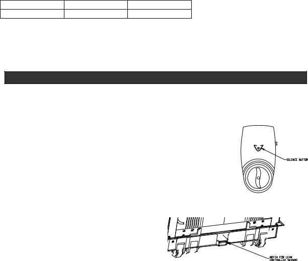
LEAK CONTROLLER INSTRUCTIONS (if applicable)
The leak controller unit is standard with model POVC2LR. It is packed inside the filter compartment ready to install. 4 AA batteries are included for initial installation. Batteries should be replaced every year to ensure full protection. The leak controller is expected to last 5 years and should be checked annually for proper function.
1.To install batteries, lift lid on flat end of leak controller and remove the battery holder.
2.Gently disconnect battery holder pack from the snap connector. Insert 4 AA batteries into battery holder slots, matching positive (+) and negative (-) terminals. Reattach snap
connector to the battery pack and insert it into battery compartment. NOTE: You should see the LED light flash three times and hear three chirps to indicate battery power.
3.Close battery lid.
4. |
Open valve by turning front knob ¼ turn clockwise to the green mark on the cover. Now |
Figure 1 |
|
the controller is open and ready to sense any water. Check that everything works |
|
|
properly by placing tip of the sensor into a small cup of water. The valve should close |
|
|
and alarm will sound. You can silence alarm by pressing button printed with a + sign |
|
|
inside a circle (see figure 1). |
|
5. |
Remove sensor from water and shake it to dry it out as |
|
|
much as possible. |
|
6. |
Mount leak controller to the water supply bracket on the |
|
|
back of the unit. The three prongs on the water supply |
|
|
bracket slide into three rectangular openings on back of |
|
|
leak controller. |
|
|
Figure 2 |
|
3

7.Snap the plastic sensor connector onto plastic base in the location marked in figure 2. The clip snaps over rib on outside of base so that terminals in the plastic housing are inside the base.
8.Open valve again. Now controller is ready to sense any water. NOTE: Water supply line should be connected directly to leak controller so it will shut water off as close to the water supply valve as possible.
Maintenance
Replace all four AA batteries yearly to ensure proper leak protection. USE
ONLY “AA” SIZE ALKALINE BATTERIES. |
|
Replace batteries if the alarm has been sounding for an undetermined length of |
|
time |
|
Replace batteries if the low battery alarm is sounding (2 beeps and 2 LED flashes |
|
in succession) |
|
Press the manual close button (see figure 3) at the annual battery change to ensure |
Figure 3 |
the valve functions properly. |
|
FILTER INSTALLATION (if applicable)
1.Make sure water is turned off and line is not under pressure.
2.Remove door by lifting out drip tray and pressing door latch down forcing top of door to lean outward. The rectangular opening under the drip tray reveals door latch.
3.Set door aside carefully to avoid scratching it.
4.See figure 4 for plumbing path. There are three water lines:
WHITE: water supply to filter and/or float valve
BLUE: exits float valve and returns to supply reservoir water
VIOLET/PURPLE (Red may be used as an alternate): for product water or reverse osmosis brine water
5.Determine where to mount filters in filter compartment and drill new 1/8” diameter holes if needed.
CARBON FILTRATION
INSTALLATION
6.If you wish to connect a
second point-of-use system such as an ice maker, you can use the purple (alternatively it will be red) colored tube already inserted through the column support. You will need to replace the elbow on it with a tee as shown in figure 4.
7. To install the carbon filtration system, cut the appropriate tube which is looped in the filter compartment. Cut it so you have enough tubing to connect your filter inlet and outlet without making the tubes too tight.
Figure 4
4

8.Connect your filters and turn on water to flush filter(s) per the manufacturer’s instructions.
9.Check for leaks. The filters are after the reservoir water valve, so if no water flows, make sure the safety float hasn’t tripped.
REVERSE OSMOSIS FILTRATION INSTALLATION
10.Connect your brine line, with flow restrictor, to the elbow on the purple (alternatively red) tubing.
11.If your supply water has a lot of sediment, you may wish to put a sediment filter before the reservoir float valve. To do so, cut the white tubing and connect your filter in-line.
12.Depending on your system, any pre-carbon filter can be placed in-line on the white tube or blue. The RO membrane must be connected to the blue tubing to work properly. The post carbon would also be on that line (see figure 4).
FIRST USE
Follow these steps when first using your water cooler and during normal maintenance operations: IMPORTANT: Do not plug in the cooler until you have filled the reservoir.
1.Upon taking your cooler out of the box, follow the steps in the section titled “CLEANING YOUR WATER RESERVOIR" on page 9. The baffle is shipped in a bag located in the filter compartment. Install it in the reservoir after cleaning reservoir and baffle. Your last step during this first cleaning will be step 21, “Put side panel back on, then place cabinet top on and tighten screws so they are snug.” After you clean and rinse cooler, you are ready to connect it to your water supply. NOTE: If you have a leak controller installed on the unit, the water supply line should be connected directly to it. This will shut the water off as close to the water supply valve as possible in event of a water leak in the cooler.
2.If you wish to install a filter in the cooler, see the section labeled “FILTER INSTALLATION” starting on page 4.
3.Turn on water supply to the cooler.
4.Check to see that water flows easily from all taps (see hot water safety instructions on page 2). IMPORTANT: You must wait until water has filled the hot tank before plugging in cooler to avoid overheating. You can check for this by pressing hot water dispense button until water flows out of the spout.
5.As cooler fills, check for leaks.
6.Plug cooler into an outlet that is properly installed and grounded.
The POU2LR cooler does not have an LCD display so it uses mechanical controls for heating and cooling the water. You can access the cold control and hot tank switch through the column support after the door is removed. See section on servicing cooler, page 11 for directions on removing the door, getting to the cold control to replace it, etc. Set cold control where you want it by using a small bladed screwdriver to rotate the thermostat knob. Turn knob clockwise for colder water, and counter-clockwise for less cold. The factory setting is in the mid cold position. The hot tank does not have an adjustable control.
Note: The rest of this first use section only applies to coolers with an LCD display.
1.Upon plugging the cooler in, nothing is displayed on the control panel. The hot tank and compressor are not operating.
2.Press “POWER” button on the cooler display (see figure 5), clock will flash 12:00 AM.
5
 Loading...