

NEW CONSTRUCTION
NuTone Model: 105T (16 volt, 15 watt) transformer must
be purchased separately.
Comply with local and national wiring codes. Bell wire
and pushbuttons(s) will also be needed to complete your
installation. Position the door chime on a wall at eye level.
Handle the chime carefully as you would any precision
i n s t r u m e n t .
W I R I N G
NOTE: Turn the house power off before wiring the
transformer to the junction box.
1. Mount the transformer to a convenient junction box (attic
location is not recommended) or to a circuit breaker box.
Connect the house power leads to the transformer leads -
black to black and white to white.
2. Run two conductor, 18 gauge wire from the transformer
and the pushbutton(s) to the Musical Chime location.
NOTE: When fastening the wiring to the wall studs
and ceiling joists, avoid short circuits that can result
in staples or clips cut through the wiring insulation.
3. Refer to Figure 2. Bring the wires through one of the
large openings in the Musical Chime's baseplate. Fasten
the baseplate to the wall with screws. If the chime is
to be mounted vertically, use the two (2) slotted holes
with T-shaped slots on the top.
4. Refer to Figure 1. Connect the transformer and
pushbutton wires to the Musical Chime's terminal board.
5. If you plan to use the Musical Chime with a NuTo n e
Radio-Intercom System or an external speaker, follow
the instructions that are provided on page 4 of this sheet
before proceeding with the installation.
6. Carefully attach the blue, yellow and green wires from
the chime's housing to the lugs marked FRONT, TRANS
and REAR respectively on the terminal block.
7. When the wiring has been completed, snap the chime's
cover onto the baseplate.
8. Reconnect power to the door chime.
TO REGISTER THIS PRODUCT, VISIT WWW.NUTONE.COM
INSTALLATION INSTRUCTIONS
READ AND SAVE THESES INSTRUCTIONS!
Model: LA-52 Series
The chime may be used with lighted or unlighted
pushbuttons. If two lighted pushbuttons are used, use only
pushbuttons that are sold by NuTo n e .
A NuTone Model: 105T (16 volt, 15 watt) transformer must
be purchased separately. N o t e : If desired, an equivalent
transformer may be purchased locally.
NOTE: The Musical Chime features terminals for oneor two-door operation but cannot be used in multiple
chime installations. Installation of the Chime is
performed in two steps: (1) at the chime site, and (2) at
the front door pushbutton.
EXISTING CONSTRUCTION
If needed, purchase NuTone Model 105T (16 volt, 15 watt)
transformer separately.
Handle the Musical Chime carefully as you would any
precision instrument. Disconnect power to the existing door
c h i m e .
1. Remove the cover from the existing door chime.
2. Disconnect the wires from the terminal strip of the existing
door chime. Mark each wire as it is removed - front,
transformer and rear.
Refer to Figure 1. If any additional wires (i.e. - side
door) are present which are not required by the
wiring diagram, cap these wires individually with a
wire nut and electrical tape.
3. Remove the existing chime base from the wall.
4. Refer to Figure 2. Determine whether the Musical Chime
will be hung vertically or horizontally. Pull the remaining
wires through one of the large holes in the baseplate.
5. Using the proper mounting screws, mount the baseplate
to the wall.
NOTE: If the Musical Chime is replacing a door chime
that was mounted horizontally, the two small round
holes in the base should align with the holes used to
mount the base of the old chime. If the Musical
Chime is replacing a door chime that was mounted
vertically, use the two slotted holes that have
T-shaped slots at the top.
6. Attach wires to the respective screw terminals (FRONT,
TRANS, REAR) that are located on the baseplate's
terminal block.
7. While holding the Musical Chime's housing in one hand,
attach the blue, yellow and green wires from the chime's
housing to the lugs marked FRONT, TRANS and REAR
respectively on the terminal block.
8. If the Musical Chime is to be used with a NuTo n e
Radio-Intercom System or an external speaker, follow
the instructions that are provided on page 3 of this sheet
before proceeding with the installation.
9. When the wiring has been completed, snap the chime's
cover onto the baseplate.
10. Reconnect power to the door chime.
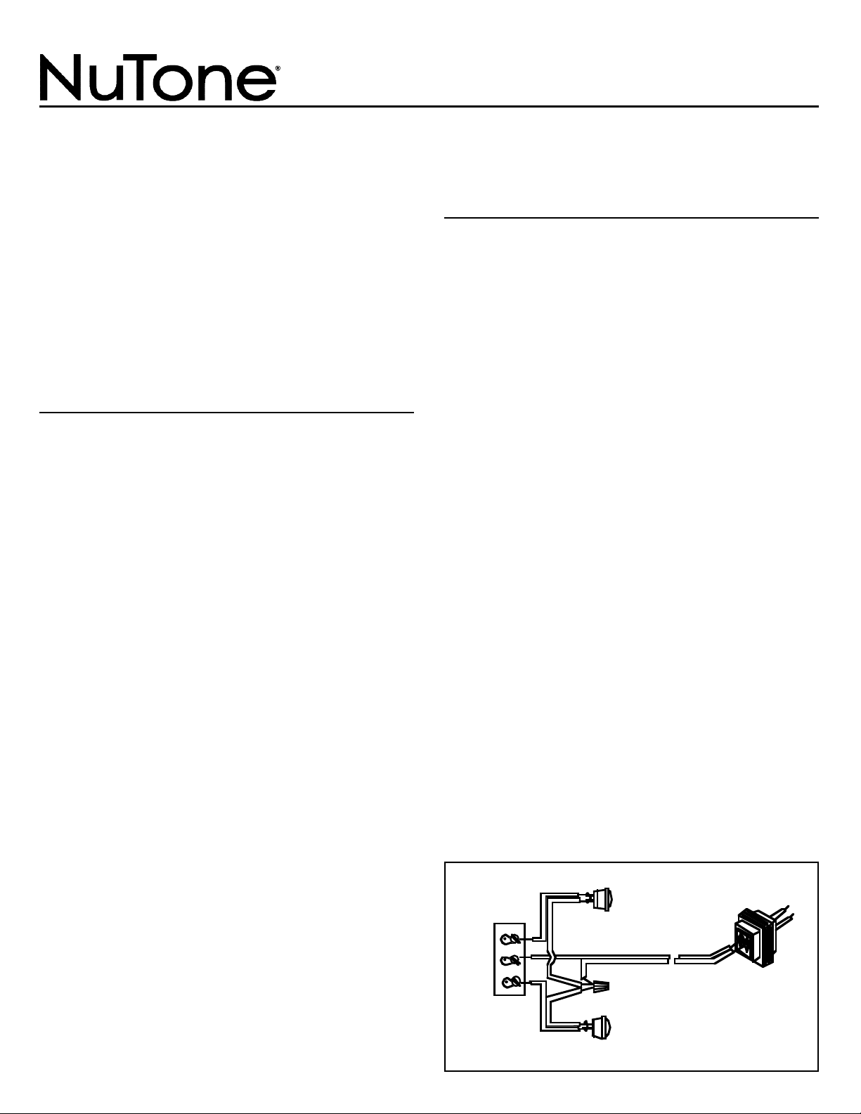
FRONT DOOR
P U S H B U T T O N
18 GA. INSULATED
2 CONDUCTOR WIRE
NUTONE
MODEL 105T
T R A N S F O R M E R
REAR DOOR
P U S H B U T T O N
M U S I C A L
C H I M E
T E R M I N A L
B O A R D
F R O N T
T R A N S
R E A R
FIGURE 1
COMMON WIRES
Musical Door Chime
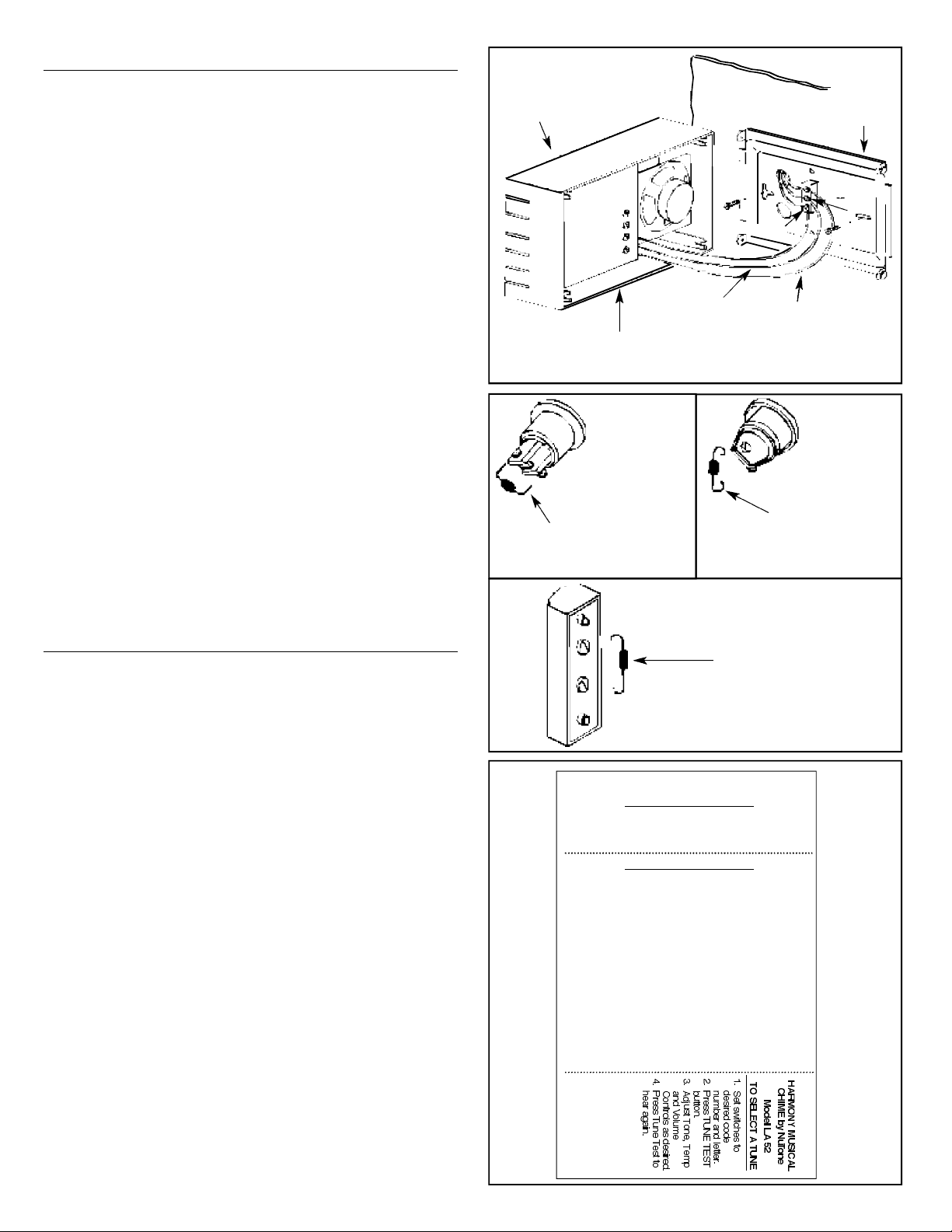
I N S TA L L I N G T H E P U S H B U T T O N S
A diode must be added to the front door pushbutton
so that power will be supplied continuously to the
Musical Chime while the tune is playing.
The diode is packed inside an envelope that is located
between the baseplate and the chime's housing.
A diode is not required at the back door pushbutton.
To add the diode to the front door's pushbutton:
1. Remove the pushbutton from the door jamb or wall.
2. Refer to Figures 3, 4 and 5. Depending upon which
type of pushbutton is being used, wire the diode to the
two (2) terminals on the pushbutton.
3. Press the front door pushbutton and listen for the
Musical Chime to play.
4. If the tune stops playing as soon as you remove your
finger from the pushbutton, the diode is installed
backwards. Simply reverse the wiring connections
on the pushbutton and test the chime again. The tune
should continue playing even after the pushbutton
is released.
5. Tighten the terminal screws and replace the pushbutton
in the door jamb or wall. Note: on metal siding, place a
small piece of insulating tape on the surface opposite
the diode to prevent shorting.
NOTE: If you are using a lighted pushbutton, the
bulb's brightness will be reduced 30-40%. This is
normal and will increase life of the bulb.
TUNE LABEL
AND TUNE SELECTION
TUNE LABEL
Refer to Figure 6. The tune label is packaged in the same
envelope as the diode.
If the Musical Chime has been mounted in the horizontal
position, tear off and discard the bottom of the label. Peel off
the back and mount the label on the inside surface of the
d o o r .
If the Musical chime has been mounted in the vertical
position, tear the label at both perforations, discard the top
portion and mount the tune list and instructions side by side
on the inside surface of the door.
TUNE SELECTION
The Musical Chime will play 1 of 24 tunes at the front door
and 2 notes of a tune at the rear door.
Refer to the Tune List and to Figure 7. Move the
switches to the desired tune. Example: For "A Bicycle Built
For Two" to be the selected tune, set the switches to "1" "A".
Press the TUNE TEST button. Set the loudness, speed
and pitch of the tune by adjusting the VOLUME, TEMPO and
TONE controls respectively. Turn the controls clockwise to
increase or counterclockwise to decrease.
NOTE: Position 5E does not play a tune. The chime
is in the off position.
H O U S I N G
LOCATE DIODE ENVELOPE
PACKED HERE
Y E L L O W
B L U E
G R E E N
B A S E
FIGURE 2
R E A R
T R A N S
F R O N T
SPKR –
SPKR +
I-COM +
I-COM –
FIGURE 3
FIGURE 5
FIGURE 4
CLIP DIODE LEADS TO
3/8" AND INSERT INTO
T E R M I N A L S
R E C E S S
M O U N T E D
P U S H B U T T O N
WRAP DIODE LEAD
AROUND EACH
TERMINAL SCREW
AND CLIP EXCESS
WRAP DIODE LEAD
AROUND EACH
TERMINAL SCREW
HARMONY MUSICAL CHIME
by NuTone Model LA 5 2
TO SELECT A TUNE
1. Set switches to desired code number and letter.
2. Press TUNE TEST button.
3. Adjust Tone, Tempo and Volume Controls as desired.
4. Press Tune Test to hear again.
TUNE LIST
1 A A Bicycle 5 C In The Good
Built for Two Old Summertime
2 A Battle Hymn 1 D I've Been Working
Of the Republic On The Railroad
3 A D i x i e 2 D Jingle Bells
4 A 1812 Overture 3 D La Cucaracha
5 A For He's A 4 D Oh! Dear, What
Jolly Good Fellow Can The Matter Be?
1 B Frere Jacques 5 D Oh Tannenbaum
2 B Give My 1 E Shave And
Regards To Broadway A Haircut
3 B G r e e n s l e e v e s 2 E Twinkle Twinkle
4 B Hail! Hail! The Little Star
Gangs All Here 3 E Westminster Chimes
5 B Hallelujah Chorus ( 4 - n o t e )
1 C Happy Birthday 4 E Yankee Doodle
2 C Hello, Ma Baby
3 C Home Sweet Home
4 C How Dry I Am
FIGURE 6
R E C E S S
M O U N T E D
P U S H B U T T O N
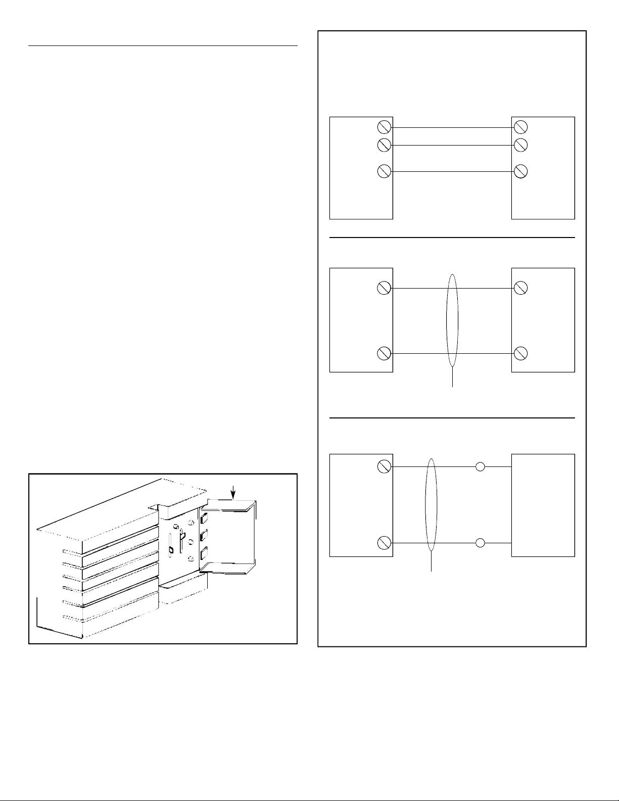
OPTIONAL FEAT U R E S
USING THE MUSICAL CHIME WITH A NUTO N E
RADIO-INTERCOM SYSTEM
If desired, the Musical Chime may be used with a NuTo n e
Radio-Intercom System. The chime signal will override
the radio-intercom but will not mute the music source.
Refer to the wiring diagram below that corresponds with
the radio-intercom system being used. Connect the wires
(use NuTone IW-2) to the Musical Chime's circuit board
terminals located inside the chime's housing.
To adjust the chime's volume so that it will be heard over
the radio-intercom, use a screwdriver to turn the recessed
control located below the I-COM terminals on the circuit
b o a r d .
USING THE MUSICAL CHIME WITH
AN EXTERNAL SPEAKER
If you do not have a NuTone Radio-Intercom System
but would like for the Musical Chime to be heard in another
section of the home, one external speaker may be used with
the Musical Chime. Note: Speaker must be purchased
separately from NuTo n e .
Use a surface-mounted speaker if the Musical Chime
needs to be heard in another room of the home.
Or, if the Musical Chime needs to be heard at the front
door, use a speaker that includes a pushbutton at that
location. NOTE: If a speaker that incudes a pushbutton
is used, the diode must be added to the pushbutton.
Connect speaker terminals to the Musical Chime's circuit
board at SPKR+ and SPKR– inside the chime's housing.
Polarity need not be considered; connect either of the
speaker's terminals to either SPKR terminal on the Musical
C h i m e .
FIGURE 7
D O O R
P L A C E
L A B E L
H E R E
SELECTOR SWITCHES
SET AT 2D,
"JINGLE BELLS"
T O N E
T E M P O
V O L U M E
E
D
C
B
A
5
4
3
2
1
T U N E
T E S T
CHIME INTERCOM WIRING
MODELS IM-3000,
IM/IMA-4000 OR IM-5000
SERIES
MODEL IM-2003
CHIME
IW-2
IW-2
INTERCOM
MASTER
CHIME
INTERCOM
MASTER
I-COM + WHITE
SPKR –
BLACK
}
C H I M E
I N P U T
I-COM +
INPUT
(COPPER)
(BLUE)
COMMON
(CENTER)
(GREY)
SPKR –
MODEL IMA-516
CHIME
INTERCOM
MASTER
I-COM +
CHIME
I-COM –
CHIME
SPKR –
METAL
CHASSIS
GROUND
SCREW
(RED/WHT
IMA-516)
Product specifications subject to change without notice.
4820 Red Bank Road, Cincinnati, Ohio 45227
Printed in U.S.A., Rev. 01/07, Part No. 84316

El carillón se puede utilizar con botones con luz o sin luz. Si
se utilizan dos botones iluminados, utilice solamente los botones
que vende NuTone. El transformador modelo NuTone 105T (16
voltios, 15 vatios) tiene que comprarse separadamente. N o t a: Si
se desea, se puede comprar un transformador equivalente
localmente. NOTA: El carillón musical tiene bornes para la
operación de una o dos puertas pero no se puede utilizar
en instalaciones de varios carillones. La instalación del
carillón se realiza en dos pasos: (1) en el lugar del carillón,
y (2) en el botón de la puerta principal.
CONSTRUCCION EXISTENTE
Si es necesario, compre el transformador NuTone modelo 105T
(16 voltios, 15 vatios) separadamente.
Manipule el carillón musical con cuidado, tal como lo haría
con cualquier instrumento de precisión. Desconecte la corriente
del carillón existente de la puerta.
1 . Retire la tapa del carillón existente de la puerta.
2. Desconecte los hilos del bloque de terminales del carillón
existente de la puerta. Marque cada hilo al retirarlo
principal (puerta principal), trans (transformador) y trasera
(puerta trasera).Vea la Figura 1. Si hay presentes más
hilos (es decir, puerta lateral) de los requeridos por el
diagrama del cableado, tape estos hilos
individualmente con una tuerca de hilos y cinta
aislante para usos eléctricos.
3. Retire la base del carillón existente de la pared.
4. Vea la Figura 2. Determine si el carillón musical va a ser
colgado vertical u horizontalmente. Tire de los hilos
restantes a través de uno de los agujeros grandes de la
chapa de montaje.
5. Utilizando los tornillos de montaje apropiados, monte la c
hapa de montaje a la pared.
NOTA: Si el carillón musical está reemplazando a un
carillón de puerta que estaba montado horizontalmente,
los dos agujeros pequeños y redondos de la base
debenestar alineados con los agujeros utilizados para
montar labase del antiguo carillón. Si el carillón
musical está reemplazando a un carillón de puerta que
estaba montado verticalmente, utilice los dos agujeros
ranurados que tiene ranuras en forma de T en la parte
s u p e r i o r .
6. Conecte los hilos a los bornes de tornillos correspondientes
(FRONT, TRANS, REAR) que están ubicados en el bloque
de terminales de la chapa de montaje.
7. Mientras sujeta la caja del carillón musical con una mano,
conecte los hilos azul, amarillo y verde de la caja del
carillón a las lengüetas de conexión marcadas con FRONT,
TRANS y REAR respectivamente en el bloque de terminales.
8. Si el carillón musical se va a utilizar con un sistema de
radiointercomunicación NuTone o con un altavoz externo
sigalas instrucciones provistas en la página 3 de este
folleto antes de continuar con la instalación.
9. Cuando haya terminado con el cableado, encaje la tapa
del carillón en la chapa de montaje.
Carillón musical de puerta
Modelo: Serie LA-52
10. Vuelva a conectar la corriente que va al carillón de la
p u e r t a .
CONSTRUCCION NUEVA
El transformador modelo NuTone 105T (16 voltios, 15
vatios) tiene que comprarse separadamente.
Cumpla con los códigos de cableado locales y
nacionales. Para completar la instalación también necesitará
el cable del timbre y los botones. Coloque el carillón de
puerta en la pared al nivel de los ojos. Manipule el carillón
musical con cuidado, tal como lo haría con cualquier
instrumento de precisión.
C A B L E A D O
NOTA: Desconecte la corriente de la casa antes de
conectar el transformador a la caja de conexiones.
1. Monte el transformador en una caja de conexiones
práctica (no se recomienda la ubicación en el ático) o en
una caja de disyuntores. Conecte los conductores de
corriente de la casa a los conductores del transformador negro con negro y blanco con blanco.
2. Lleve dos hilos conductores de calibre 18 desde el
transformador y los botones a la ubicación del carillón
mu s i c a l .
NOTA: Cuando sujete el cableado a los montantes de
la pared y a las viguetas del techo, evite los
cortocircuitos debidos al atravesar el aislamiento de
los hilos con las grapas o pinzas.
3. Vea la Figura 2. Traiga los hilos a través de una de las
aberturas grandes de la chapa de montaje del carillón
musical. Sujete la chapa de montaje a la pared con los
tornillos. Si va a montar el carillón verticalmente, utilice
los dos (2) agujeros ranurados con ranuras en forma de T
en la parte superior.
4. Vea la Figura 1. Conecte los hilos del transformador y de
los botones al cuadro de bornes del carillón musical.
5. Si piensa utilizar el carillón musical con un sistema de
radiointercomunicación NuTone o con un altavoz externo,
siga las instrucciones provistas en la página 4 de este
folleto antes de continuar con la instalación.
6. Conecte con cuidado los hilos azul, amarillo y verde de la
caja
del carillón a las lengüetas de conexión marcadas con
FRONT, TRANS Y REAR respectivamente en el bloque de
t e r m i n a l e s .
7 . Cuando haya terminado con el cableado, encaje la tapa del
carillón en la chapa de montaje.
8. Vuelva a conectar la corriente que va al carillón de la puerta.
BOTON DE LA
PUERTA PRINCIPAL
2 HILOS CONDUCTORES
AISLADOS DE CALIBRE 18
NUTONE
MODELO 105T
T R A N S F O R M A D O R
BOTON DE LA
P U E R T A
T R A S E R A
CUADRO DE
BORNES DEL
C A R I L L O N
M U S I C A L
P R I N C I P A L
T R A N S
T R A S E R A
FIGURA 1
HILOS NEUTROS
PARA COLOCAR ESTE PRODUCTO, VISITE WWW.NUTONE.COM
INSTRUCCIONES DE INSTALACION
¡LEA Y GUARDE ESTAS INSTRUCCIONES!

I N S TALACION DE LOS BOTO N E S
Hay que añadir un diodo al botón de la puerta principal
para que la corriente sea suministrada de manera
continua al carillón musical mientras está sonando la
m e l o d í a .
El diodo está empaquetado dentro de un sobre ubicado
entre la chapa de montaje y la caja del carillón.
No se requiere un diodo en el botón de la puerta trasera.
Para añadir el diodo al botón de la puerta principal:
1. Retire el botón de la jamba de la puerta o pared.
2. Vea las Figuras 3, 4 y 5. Dependiendo del tipo de botón
utilizado, conecte el diodo a los dos (2) bornes del botón.
3. Pulse el botón de la puerta principal y escuche la melodía
del carillón musical.
4. Si la melodía se detiene tan pronto como deja de apretar
el botón, el diodo está instalado al revés. Simplemente
invierta las conexiones del cableado del botón y pruebe
de nuevo el carillón. La melodía debe de continuar
sonando incluso después de soltar el botón.
5. Apriete los tornillos del borne y cambie el botón de la
jamba de la puerta o pared. N o t a: en las paredes con
forro de chapa metálica ponga un trozo pequeño de
cinta aislante en la superficie opuesta al diodo para
evitar un cortocircuito.
NOTA: Si está utilizando un botón con luz, la
brillantez de la bombilla se reducirá en un 30 ó 40%.
Esto es normal y aumentará la duración de la
b o m b i l l a .
E T I Q U E TA DE LA MELODIA Y
SELECCION DE LA MELODIA
ETIQUETA DE LA MELODIA
Vea la Figura 6. La etiqueta de la melodía está
empaquetada en el mismo sobre que el diodo.
Si ha montado el carillón musical horizontalmente,
desprenda y deseche la parte inferior de la etiqueta. Pele la
parte posterior de la etiqueta y monte esta última en la
superficie interior de la puerta.
Si ha montado el carillón musical verticalmente, desprenda
la etiqueta en ambas perforaciones, deseche la parte superior
de la etiqueta y monte la lista de melodías y las instrucciones
lado con lado en la superficie interior de la puerta.
SELECCION DE LA MELODIA
El carillón musical toca de 1 a 24 melodías en la puerta
principal y 2 notas de una melodía en la puerta trasera.
Vea la lista de melodías y la Figura 7. Cambie los
interruptores a la melodía deseada. Ejemplo: Para
seleccionar la melodía “A Bicycle Built For Two”, ponga los
interruptores en las posiciones “1” “A”.
Pulse el botón de TUNE TEST. Ajuste la sonoridad, la
velocidad y el tono ajustando los controles del VOLUME,
TEMPO Y TONE (volumen, ritmo y tono) respectivamente.
Gire los controles en el sentido de las agujas del reloj para
subir o en el sentido contrario a las agujas del reloj para
bajar.
NOTA: La posición 5E no hace sonar la melodía. El
carillón se encuentra en la posición de apagado.
C A J A
UBIQUE EL SOBRE AQUI
E M P A Q U E T A D O
A M A R I L L O
A Z U L
V E R D E
B A S E
FIGURA 2
T R A S E R A
T R A N S
P R I N C I P A L
SPKR –
SPKR +
I-COM +
I-COM –
FIGURA 3
FIGURA 5
FIGURA 4
RECORTAR LOS
CONDUCTORES DEL
DIODO A 3/8" E
INSERTARLOS EN LOS
B O R N E S
B O T O N
EMBUTIDO
WNROLLAR EL
CONDUCTOR DEL
DIODO ALREDEDOR
DE CADA TORNILLO
DEL BORNEY
RECORTAR EL
E X C E S O
ENROLLAR EL
CONDUCTOR DEL
DIODO ALREDEDOR DE
CADA TORNILLO DEL
B O R N E
HARMONY MUSICAL CHIME
by NuTone Model LA 5 2
TO SELECT A TUNE
1. Set switches to desired code number and letter.
2. Press TUNE TEST button.
3. Adjust Tone, Tempo and Volume Controls as desired.
4. Press Tune Test to hear again.
TUNE LIST
1 A A Bicycle 5 C In The Good
Built for Two Old Summertime
2 A Battle Hymn 1 D I've Been Working
Of the Republic On The Railroad
3 A D i x i e 2 D Jingle Bells
4 A 1812 Overture 3 D La Cucaracha
5 A For He's A 4 D Oh! Dear, What
Jolly Good Fellow Can The Matter Be?
1 B Frere Jacques 5 D Oh Tannenbaum
2 B Give My 1 E Shave And
Regards To Broadway A Haircut
3 B G r e e n s l e e v e s 2 E Twinkle Twinkle
4 B Hail! Hail! The Little Star
Gangs All Here 3 E Westminster Chimes
5 B Hallelujah Chorus ( 4 - n o t e )
1 C Happy Birthday 4 E Yankee Doodle
2 C Hello, Ma Baby
3 C Home Sweet Home
4 C How Dry I Am
FIGURA 6
B O T O N
E M B U T I D O

CARACTERISTICAS OPCIONALES
PARA UTILIZAR EL CARILLON MUSICAL CON
UN SISTEMA DE RADIOINTERCOMUNICACION
N U T O N E
Si se desea, se puede utilizar el carillón musical con un
sistema de radiointercomunicación NuTone. La señal del
carillón anulará la radiointercomunicación pero no
desconectará la fuente de música.
Vea el siguiente diagrama del cableado que
corresponda al sistema de radiointercomunicación que se
esté utilizando. Conecte los hilos (utilice NuTone IW-2) a
los bornes de la placa de circuito impreso del carillón
musical ubicada dentro de la caja del carillón.
Para ajustar el volumen del carillón para que se pueda
oír por encima de la radiointercomunicación, utilice un
destornillador para girar el control embutido ubicado debajo
de los bornes I-COM en la placa de circuito impreso.
PARA UTILIZAR EL CARILLON MUSICAL CON
UN ALTAVOZ EXTERNO
Si no tiene un sistema de radiointercomunicación NuTone
pero le gustaría que el carillón musical se oyera en otra sección de
la casa, se puede utilizar un altavoz externo con el carillón
musical. Nota: El altavoz se compra separadamente a NuTone.
Utilice un altavoz de montaje en superficies si es necesario
oír el carillón musical en otra habitación de la casa.
O bien, si es necesario oír el carillón musical en la puerta
principal, utilice un altavoz que incluya un botón en esa ubicación.
NOTA: Si se utiliza un altavoz que incluye un botón,
habrá que añadir el diodo al botón.
Conecte los bornes del altavoz a la placa de circuito impreso
del carillón musical al ALTAVOZ + Y ALTAVOZ - dentro de la caja
del carillón. No hay que tener en cuenta la polaridad; conecte
cualquiera de los bornes del altavoz a cualquier borne de los
ALTAVOCES del carillón musical.
CABLEADO DEL CARILLON CON EL SISTEMA DE
INTERCOMUNICACION
MODELOS IM-3000,
IM/IMA-4000 OR IM-5000
MODEL0 IM-2003
CHIME
IW-2
IW-2
MATRIZ DEL
SISTEMA DE INTER-
COMUNICATCON
CARILLON
MATRIZ DEL
SISTEMA DE INTER -
COMUNICATCION
I-COM + BLANCO
SPKR – NEGRO
}
E N T R A D A
D E L
C A R I L L O N
I-COM +
ENTRADA
(COBRE)
(AZUL)
NEUTRO
(CENTRO)
(GRIS)
ALTAVOZ –
MODELO IMA-516
CARILLON
MATRIZ DEL
SISTEMA DE INTER-
COMUNICATCION
I-COM +
CARILLON
I-COM –
CARILLON
SPKR –
TORNILLO DE
PUESTA A
TIERRA DEL
BASTIDOR
METALICO
(ROJO/BLANCO
IMA 516)
FIGURA 7
T O N E
T E M P O
V O L U M E
E
D
C
B
A
5
4
3
2
1
T U N E
T E S T
PONGA
AQUI LA
ETIQUETA
CONMUTADORES
SELECTORES
AJUSTADOS EN 2D,
“JINGLE BELLS”
PUERTA

Las especificaciones del producto están sujetas a cambio sin previo aviso
4820 Red Bank Road, Cincinnati, Ohio 45227
Impreso en los EE.UU., Rev. 01/07, Pieza Nº 84316

NOUVELLE CONSTRUCTION
Il faut acheter séparément le transformateur NuTo n e
Modèle 105T (16 V, 15 W).
Il faut se conformer aux codes locaux et nationaux. Il faut
aussi utiliser du fil de sonnette et un (des) bouton(s)poussoir(s) pour faire l'installation. Le carillon musical doit
être vu aussi bien qu'entendu. Installer le carillon musical au
niveau des yeux. Manipuler le carillon avec soin, comme
n'importe quel instrument délicat.
B R A N C H E M E N T
NOTE: Couper le courant de la maison avant de
brancher un transformateur avec une boite de jonction.
1. Monter le transformateur près d'une boite de jonction
pratique (Installation dans un grenier non recommandée)
ou près d'un coupe circuit. Connecter le fil d'alimentation
de la maison avec le fil du transformateur – fil noir sur fil
noir et fil blanc sur fil blanc.
2. Passer les fils conducteurs jumeaux calibre 18 du
transformateur et du bouton poussoir jusqú à
l'emplacement du LA-52.
NOTE: En attachant les fils aux murs et aux poutres du
plafond, éviter les courts circuits qui peuvent survenir
quand les agrafes ou les clous passent à travers
l'isolant des fils.
3. Voir Figure 2. Passer les fils à travers un des larges trous
situés dans la plaque de base du LA-52. Fixer la plaque de
base sur le mur avec des vis. Si elle est montée
verticalement, utiliser les deux trous rainures en T en les
positionnant au sommet.
4. Voir Figure 1. Brancher les fils du transformateurs et du
bouton sur les bornes du boitier du LA-52.
5. Si vous envisagez d'utiliser l'harmonie LA-52 avec un
interpnone NuTone ou un haut-parleur exterieur, suivez les
instructions de ces accessoires avant de procéder.
6. Tenir la boite du LA-52 dans une main, attacher les fils
bleus, jaunes et verts aux attaches respectivement
marquées (AVANT, TRANS, ARRIERE) sur les bornes de
la base.
7. Quand tous les fils sont connectés, engager le boitier du
LA-52 sur la base en engageant les quatre coins.
8. Rebrancher le courant du carillon.
POUR ENREGISTRER CE PRODUIT, VISITEZ WWW.NUTONE.COM
INSTRUCTIONS D'INSTALLATION
LIRE ET CONSERVER CES INSTRUCTIONS!
Modèle: LA-52 Série
Il est possible d'utiliser le carillon avec des boutonspoussoirs illuminés ou non. Si deux boutons-poussoirs sont
utilisés, il ne faut utiliser que des boutons-poussoirs vendus
par NuTo n e .
Il faut acheter séparément un transformateur NuTo n e
Modèle 105T (16 V, 15 W). R e m a r q u e : Si désiré, il est
possible d'acheter localement un transformateur équivalent.
Remarque: Le carillon musical est équipé de bornes
pour utilisation avec une ou deux portes, mais il n'est
pas possible de l'utiliser dans une installation avec
plusieurs carillons. L'installation d'un carillon se fait
en deux étapes: (1) à l'emplacement du carillon, (2) au
bouton-poussoir de la porte d'entrée.
CONSTRUCTION EXISTA N T E
Si nécessaire, acheter séparément un transformateur
NuTone Model 105T (16 V, 15 W).
Manipuler le carillon musical avec précaution, comme
n'importe quel instrument délicat. Couper l'alimentation
secteur du carillon existant.
1. Oter le couvercle du carillon existant.
2. Debrancher les fils de la borne du carillon existant, en
marquant chaque fil quand vous le retirez – Avant, Trans,
A r r i è r e .
Voir Figure 1. Tout fil supplémentaire (par exemple:
commutateur ou coté) doit être neutralisé au moyen
d'une cosse ou de ruban adhésif électrique et
repoussés dans le trou du mur. Ces fils ne sont pas
nécessaires pour le LA-52.
3. Retirer le support du carillon existant du mur.
4. Voir Figure 2. Décider si vous voulez que le LA-52 soit
suspendu verticalement ou horizontalement. Tirer les fils
restants par un des grands trous dans la plaque de base
qui donne le meilleur camouflage de la cavité murale.
5. Monter la base dans le mur.
NOTE: Si le LA-52 remplace un carillon monte
horizontalement, les deux petits trous de la nouvelle
plaque doivent s'aligner avec les trous utilisés pour
monter l'ancienne base. Si le LA-52 remplace un
carillon monté verticalement, utiliser les deux trous
rainures en T positionnés en haut.
6. Attacher les fils à leurs vis respectives (AVANT, TRANS,
ARRIERE) sur les bornes de la base.
7. Tenir la boite du LA-52 dans une main, attacher les fils
bleus, jaunes et verts aux attaches respectivement
marquees (AVANT, TRANS, ARRIERE) sur les bornes
de la base.
8. Si vous envisagez d'utiliser l'harmonie LA-52 avec un
interphone NuTone ou un haut-parleur exterieur, suivez
les instructions de ces accessories avant de proceder.
9. Quand tous les fils sont connectés, engager le boitier du
LA-52 sur la base en engageant les quatre coins.
10. Rebrancher le courant du carillon.
BOUTON POUSSOIR DE
LA PORTE D'ENTREE
FIL DOUBLE ISOLE
CALIBRE 18
T R A N S F O R M A T E U R
NUTONE 105T
BOUTON POUSSOIR DE
LA PORTE ARRIERE
T A B L E A U
T E R M I N A L
L A - 5 2
A V A N T
T R A N S
A R R I E R E
FIGURE 1
FILS COMMUNS
Carillon Musical de Porte

B O I T I E R
PLACER LA DIODE DANS UNE
ENVELOPPE EMBOLLIE ICI
J A U N E
B L E U
V E R T
B A S E
FIGURE 2
A R R I E R E
T R A N S
A V A N T
FIGURE 3
FIGURE 5
FIGURE 4
AGRAFER LE FIL DE
LA DIODE A 3/8"
(9.52mm) ET
INTRODUIRE DANS
LES BORNES
B O U T O N S
P O U S S O I R S
E N C A S T R E S
ENROULER LE FIL
DE LA DIODE
AUTOUR DE LA VIS
DE CHAQUE BORNE
ET AGRAFER
L ' E X C E D E N T
ENROULER LE FIL DE LA
DIODE AUTOUR DE LA
VIS DE CHAQUE BORNE
I N S TA L L AT I O N
DES BOUTONS POUSSOIRS
Il faut ajouter une diode au bouton-poussoir de la
porte d'entrée pour que le carillon soit alimenté
continuellement alors qu'il joue l'air.
La diode est emballée dans une enveloppe qui se trouve
entre la plaque de base et le boîtier du carillon.
Il n'y a pas besoin de diode sur la porte de jardin.
Pour ajouter la diode sur le bouton-poussoir de la porte
d ' e n t r é e :
1. Retirer le bouton du montant de la porte ou du mur.
2. Voir Figures 3, 4 and 5. Brancher la diode aux deux
extremités sur le bouton poussoir, selon la forme de
votre bouton poussoir.
3. Appuyer sur le bouton poussoir de la porte de devant et
écouter le carillon jouer.
4. Si la musique s'arrête dès que vous ôtez votre doigt du
bouton, la diode est montée a l'evers. Inversez les
branchement sur le bouton poussoir et Essayez de
nouveau. Cette fois, la musique devrait continuer de
jouer même apres que le bouton soit relaché.
5. Serrez les vis des bornes et replacer le bouton poussior
sur le montant de la porte ou sur le mur. (Sur un
montant métallique, placez un petit morceau de ruban
isolant sur la surface opposée a la diode pour éviter un
court circuit.)
NOTE: Si vous utilisez un bouton poussoir
eclairé, la luminosité de la lampe sera réduite de 30
a 40% – Ceci est normal et augmentera la durée de
vie de la lampe.
LISTE DES MELODIES
ET SELECTIONN
LISTE DES MELODIES
Voir Figure 6. La liste des mélodies est emblallée dans la
même enveloppe que la diode placee entre la plaque de
base et la boitier du carrillon.
Si vous avez monté le LA-52 horizontalement, detacher le
bas de la liste, décoller l'arrière et fixer la Fiche a l'intérieur de
la porte.
Si vous avez monté le LA-52 verticalement, détacher les
fiches à chaque perforation, prendre le haut et fixer la liste
des mélodies et les instructions côte a côte.
SELECTION D'UN AIR
Le carillon musical joue un de 24 airs pour la porte d'entrée
et deux notes pour la porte de jardin.
Consulter la liste des airs et la Figure 7. M e t t r e
l'interrupteur sur l'air désiré. Par exemple - Pour choisir
«A bicycle built for two», mettre les commutateurs sur «1» «A».
Appuyer sur le bouton TUNE TEST. Régler le volume,
la vitesse et le ton de l'air en réglant les commandes de
VOLUME, TEMPO et TONE respectivement. Faire tourner
les boutons dans le sens des aiguilles d'une montre pour
augmenter et dans le sens inverse pour diminuer.
Remarque: La position 5E ne joue aucun air. C'est la
position d'arrêt du carillon.
CARILLON MUSICAL “HARMONIE”
par NuTone Modèle LA 5 2
SELECTION DES MELODIES
1. Mettre les boutons sur les lettres et chiffres desirés.
2. Appuyer sur le bouton d'essai des mélodies.
3. Règler la tonalité, le tempo et le volume comme desiré.
4.
Appuyer sur le bouton d essai des mélodies de nouveau pour vérifier.
TUNE LIST
1 A A Bicycle 5 C In The Good
Built for Two Old Summertime
2 A Battle Hymn 1 D I've Been Working
Of the Republic On The Railroad
3 A D i x i e 2 D Jingle Bells
4 A 1812 Overture 3 D La Cucaracha
5 A For He's A 4 D Oh! Dear, What
Jolly Good Fellow Can The Matter Be?
1 B Frere Jacques 5 D Oh Tannenbaum
2 B Give My 1 E Shave And
Regards To Broadway A Haircut
3 B G r e e n s l e e v e s 2 E Twinkle Twinkle
4 B Hail! Hail! The Little Star
Gangs All Here 3 E Westminster Chimes
5 B Hallelujah Chorus ( 4 - n o t e )
1 C Happy Birthday 4 E Yankee Doodle
2 C Hello, Ma Baby
3 C Home Sweet Home
4 C How Dry I Am
FIGURE 6
B O U T O N S
P O U S S O I R S
E N C A S T R E S
BOUTONS POUSSOIRS
MONTES EN SURFACE
HAUT-PARLEUR –
HAUT-PARLEUR +
INTERPHONE +
INTERPHONE –

ACCESSORIES OPTIONNELS
U T I L I S ATION AV E C
INTERPHONE RADIO NUTO N E
Vous pouvez brancher le LA-52 à un systeme d'interphone
radio. Le signal du carillon LA-52 surpassera
la communication radio mais ne changera pas la source
m u s i c a l e .
Suivez le diagramme de câblage qui s'adapte à votre
systeme d'interphones. (Voir ci-dessous.) Brancher les fils
( NuTone IW-2) aux bornes du tableau de branchement du
LA-52 à l'intérieur du boitier du carillon.
Pour ajuster le volume du LA-52 plus fort que l'interphone
radio, utiliser un tournevis pour tourner un bouton juste en
dessous des bornes de l'interphone sur le tableau
de branchement.
U T I L I S ATION DU CARILLON MUSICAL
AVEC UN HAUT- P ARLEUR EXTERIEUR
Si un système de radio-interphone NuTone n'est pas
installé et s'il est désirable d'entendre le carillon musical dans
une autre partie de la maison, il est possible d'utiliser un
haut-parleur extérieur. Remarque: Il faut acheter
séparément le haut-parleur extérieur de NuTo n e .
Utiliser un haut-parleur de surface s'il faut entendre le
carillon musical dans une autre pièce.
Pour entendre le carillon musical à la porte d'entrée,
utiliser à cet endroit un haut-parleur équipé d'un boutonpoussoir. Remarque: Si on utilise un haut-parleur équipé
d'un bouton poussoir, il faut installer une diode au
b o u t o n - p o u s s o i r .
Brancher les bornes du haut-parleur sur la carte du carillon
musical à SPKR +et SPKR – à l'intérieur du boîtier du
carillon. Il n'est pas nécessaire de respecter la polarité.
Brancher n'importe quel fil du haut-parleur sur n'importe
quelle borne du carillon musical.
CABLAGE INTERPHONE-CARILLON
MODELES IM-3003,
IMA-4006 & IM-5006
MODELE IM-2003
CARILLON
IW-2
IW-2
BOITIER DE
L'INTERPHONE
CARILLON
BOITIER DE
L'INTERPHONE
BLANC
HAUTPARLEUR –
NOIR
}
COURANT
(CUIVRE)
(BLEU)
COMMUN
(CENTER)
(GRISE)
HAUTPARLEUR –
FIGURE 7
P O R T E
P L A C E R
L A
L A B E L
I C E
COMMUTATEUR PLACE
SUR 2D:
VIVE LE VENT
T O N A L I T I E S
T E M P O
V O L U M E
E
D
C
B
A
5
4
3
2
1
ESSAI DES
M E L O D I E S
MODELE IMA-516
CARILLON
BOITIER DE
L'INTERPHONE
CARILLON
CARILLON
HAUTPARLEUR –
VIS DE
MASSE SUR
CHASSIS
METALLIQUE
(IMA-516
ROUGE/
BLANC)
C A R I L L O N
C O U R A N T
INTERPHONE +
INTERPHONE +
INTERPHONE +
INTERPHONE –

Les caractéristiques peuvent être modifiées sans préavis
4820 Red Bank Road, Cincinnati, Ohio 45227
Imprimé aux E.-U., Rev. 01/07, Piéce no. 84316
 Loading...