

Page 1
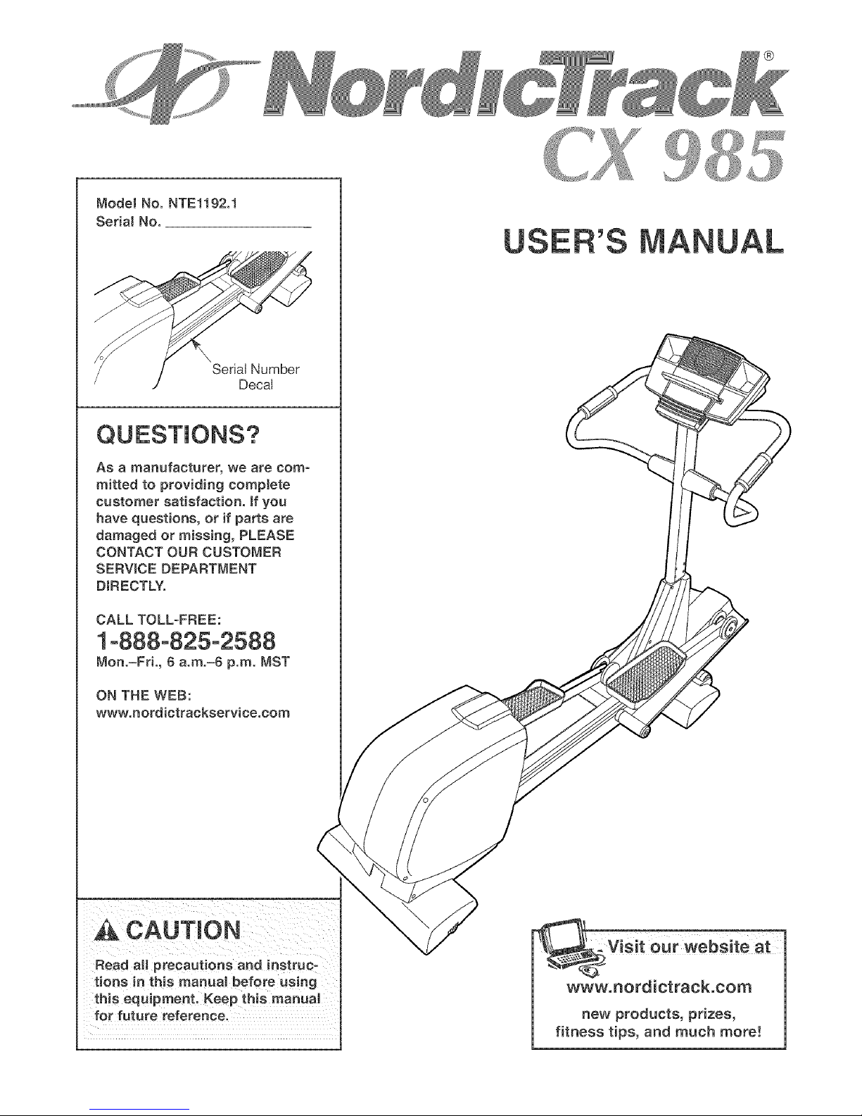
ModelNo.NTE1192.1
SerialNo.
SerialNumber
Decal
QUESTIONS?
®
USER'S
As a manufacturer, we are corn =
rnitted to providing complete
customer satisfaction. If you
have questions, or if parts are
damaged or missing, PLEASE
CONTACT OUR CUSTOMER
SERVICE DEPARTMENT
DIRECTLY.
CALL TOLL-FREE:
1°888°825°2588
Mon.=Fri., 6 a.rn.=6 p.m. MST
ON THE WEB:
www.nordictrackservice.corn
A CAUTION
Read aH precautions and instruc-
tions in this manual before using
this equipment. Keep this rnanuaJ
for future reference, new products, prizes,
fitness tips, and much more!
Page 2

TABLE OF CONTENTS
IMPORTANT PRECAUTIONS ................................................................ 3
BEFORE YOU BEGIN ...................................................................... 4
ASSEMBLY ............................................................................... 5
HOW TO USE THE ELLIPTICAL EXERCISER .................................................. 10
MAINTENANCE AND TROUBLESHOOTING ................................................... 22
CONDITIONING GUIDELINES ............................................................... 23
PART LIST .............................................................................. 24
EXPLODED DRAWING .................................................................... 26
HOW TO ORDER REPLACEMENT PARTS ............................................. Back Cover
LIMITED WARRANTY .............................................................. Back Cover
NordicTrack is a registered trademark of ICON IP, Inc,
2
Page 3

_ WARNING: Toreducethe.ekofso.ousinjury,reedthefo,owingimportantprecau-
tionsbefore using the elliptical exerciser.
1. Reed sJl instructions in this msnusJ end sJl
warnings on the elliptical exerciser before
using the eJiiptiesl exerciser.
It is the responsibility of the owner to ensure
that ell users of the elliptical exerciser are
adequately informed of sH precautions.
3. The elJiptiesJ exerciser is intended for
in-home use only. Do not use the elliptical
exerciser in s eommereisJ, rental, or instituo
tionsl setting.
4. Keep the elliptiesJ exerciser indoors, sway the pedals will continue to move until the
from moisture end dust. PJaee the elliptical flywheeJ stops.
exerciser on s level surface, with a met
beneath it to protect the floor or carpet.
Make sure that there is enough clearance
around the elliptical exerciser to mount, dis-
mount, end use the elliptical exerciser.
5. inspect snd properly tighten sit parts regu-
larly. Fieplsce any worn parts immediately.
6. Keep chiJdren under age 12 and pets sway
from the elliptical exerciser st sJJtimes.
11. If you feel pain or dizziness while exerciso
ing, stop immedisteJy end cool down.
12. The pulse sensor is not s medical device.
Various factors, including the user's move-
ment, may affect the accuracy of heart rate
readings. The pulse sensor is intended onJy
as sn exercise aid in determining heart rate
trends in general
13. When you stop exercising, show the pedals
to slowly come to s complete stop. The eJHpo
ticai exerciser does not have s free wheel;
14. Always unplug the power cord immediately
after use end before cleaning the elliptical
exerciser,
15.The deesJ shown beJow has been placed on
the elliptical exerciser, if the decal is missing
or illegible, please ceil the toil-free telephone
number on the front cover of this manual
snd order a free replacement decal Apply
the decal in the location shown.
7. The elliptical exerciser should not be used
by persons weighing more than 250 pounds.
8. Wear appropriate exercise clothing when
using the eIHptiesl exerciser. ARways wear
athletic shoes for foot protection.
9. Always hoJd the handlebars when mounting,
dismounting, or using the elliptical exerciser.
10. Keep your back straight when using the ellip-
tical exerciser: do not arch your back.
A WAR NING: Beforebeginningth_sorshyexerciseprogram,consultyourphysician.
This is especially important for persons over the age of 35 or persons with pre-existing heaJtb probo
lame. Bead alJ instructions before using, iCON assumes no responsibility for persons1 injury or
property damage sustained by or through the use of this product.
Page 4
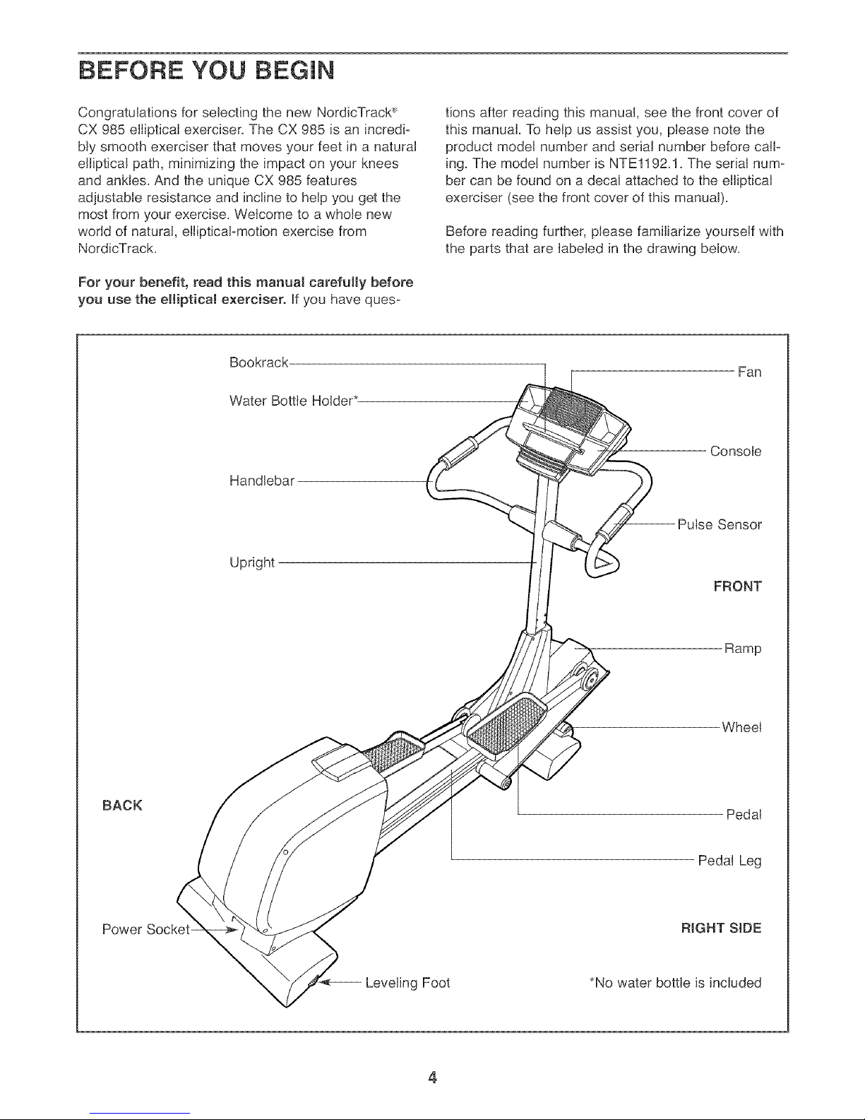
BEFORE YOU BEGIN
Congratulations for selecting the new NordicTrack _'
CX 985 elliptical exerciser. The CX 985 is an incredi-
bly smooth exerciser that moves your feet in a natural
elliptical path, minimizing the impact on your knees
and ankles. And the unique CX 985 features
adjustable resistance and incline to help you get the
most from your exercise. Welcome to a whole new
world of natural, elliptical-motion exercise from
NordicTrack.
For your benefit, read this manual carefully before
you use the elliptical exerciser. If you have ques-
Bookrack
Water Bottle Holder*
Handlebar
tions after reading this manual, see the front cover of
this manual. To help us assist you, please note the
product model number and serial number before call-
ing. The model number is NTEl192.1. The serial num-
ber can be found on a decal attached to the elliptical
exerciser (see the front cover of this manual).
Before reading further, please familiarize yourself with
the parts that are labeled in the drawing below.
Fan
Console
-- Pulse Sensor
Upright
FRONT
Ramp
Wheel
BACK
Power Socket- RIGHT StDE
Pedal
Pedal Leg
Leveling Foot
4
*No water bottle is included
Page 5
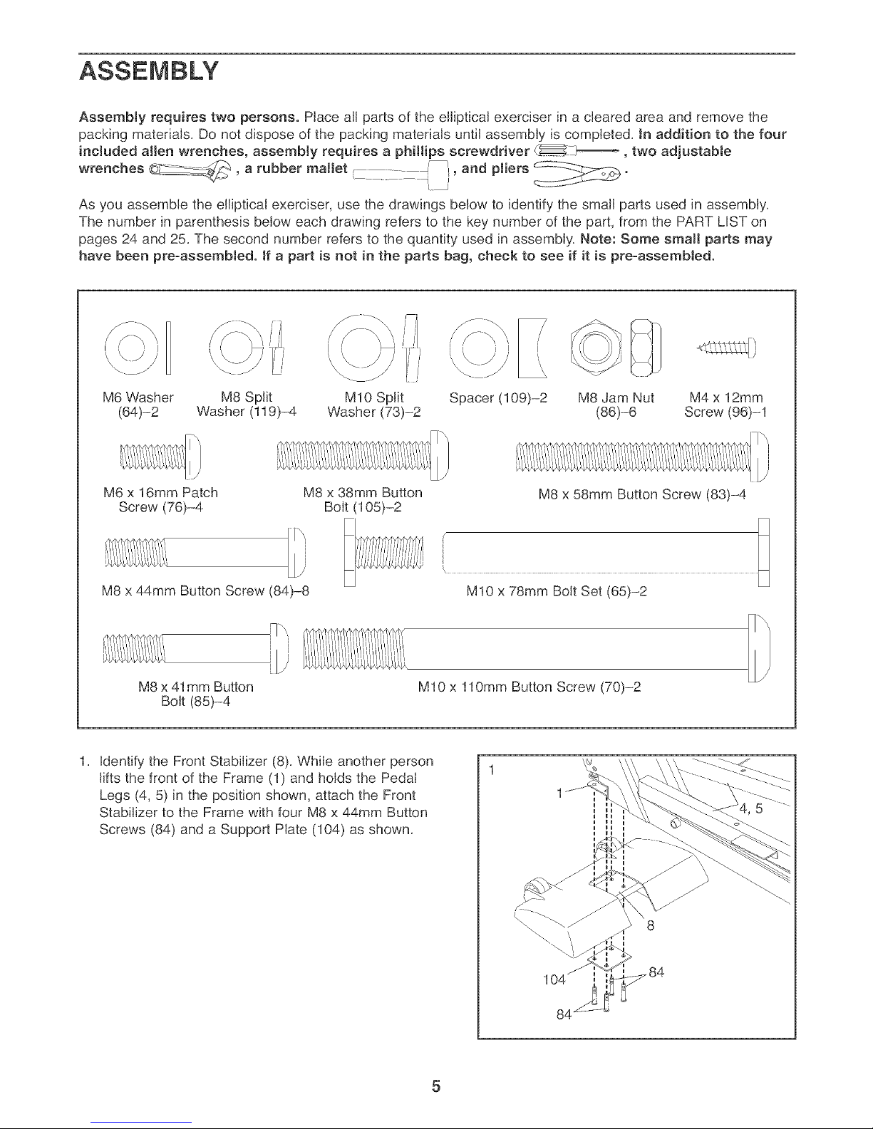
AssembJy requires two persons. PJace aJlparts of the elJipticaJ exerciser Jna cleared area and remove the
packing materiaJs. Do not dispose of the packing materiaJs until assembly is completed. Jnaddition to the four
included allen wrenches, assembly requires a phillips screwdriver _._ _, two adjustabJe
wrenches o__, a rubber mallet • I_, and pJiers
, ....... },
As you assemble the elliptical exerciser, use the drawings below to identify the smalJ parts used in assembJy.
The number in parenthesis below each drawing refers to the key number of the part, from the PART LIST on
pages 24 and 25. The second number refers to the quantity used in assembJy. Note: Some small parts may
have been preoassembJed, tf a part is not in the parts bag, check to see if it is preoassembJed.
M6 Washer M8 Split MIO Split Spacer (109)-2 M8 Jam Nut M4 x 12mm
(64)-2 Washer (119)-4 Washer (73)-2 (86)-6 Screw (96)-1
M6 x 16mm Patch
Screw (76)-4
M8 x 38mm Button
Bolt (105)-2
M8 x 44mm Button Screw (84)-8
M8 x 41mm Button
Bolt (85)-4
Identify the Front StabiJizer (8). While another person
lifts the front of the Frame (1) and holds the Pedal
Legs (4, 5) in the position shown, attach the Front
Stabilizer to the Frame with four M8 x 44mm Button
Screws (84) and a Support Plate (104) as shown.
M8 x 58mm Button Screw (83)-4
MIO x 78mm Bolt Set (65)-2
MIO x 110mm Button Screw (70)-2
\
Page 6
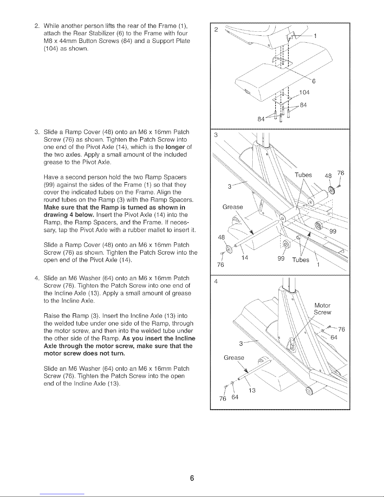
While another person lifts the rear of the Frame (1),
2. 2
attach the Rear Stabilizer (6) to the Frame with four
M8 x 44mm Button Screws (84) and a Support Plate
(104) as shown.
\ 104
Slide a Ramp Cover (48) onto an M6 x 16mm Patch
Screw (76) as shown. Tighten the Patch Screw into
one end of the Pivot Axle (14), which is the longer of
the two axles. Apply a small amount of the included
grease to the Pivot Axle.
Have a second person hold the two Ramp Spacers
(99) against the sides of the Frame (1) so that they
cover the indicated tubes on the Frame. Align the
round tubes on the Ramp (3) with the Ramp Spacers.
Make sure that the Ramp is turned as shown in
drawing 4 below. Insert the Pivot Axle (14) into the
Ramp, the Ramp Spacers, and the Frame. If neces-
sary, tap the Pivot Axle with a rubber mallet to insert it.
Slide a Ramp Cover (48) onto an M6 x 16mm Patch
Screw (76) as shown. Tighten the Patch Screw into the
open end of the Pivot Axle (14).
Slide an M6 Washer (64) onto an M6 x 16mm Patch
Screw (76). Tighten the Patch Screw into one end of
the Incline Axle (13). Apply a small amount of grease
to the Incline Axle.
Raise the Ramp (3). Insert the Incline Axle (13) into
the welded tube under one side of the Ramp, through
the motor screw, and then into the welded tube under
the other side of the Ramp. As you insert the Incline
A×Je through the motor screw, make sure that the
motor screw does not turn.
Slide an M6 Washer (64) onto an M6 x 16mm Patch
Screw (76). Tighten the Patch Screw into the open
end of the Incline Axle (13).
Grease
48
76
Grease
64
\\
48
'\
\
14
99 Tubes
1
Motor
Screw
76
\
\
13
6
Page 7
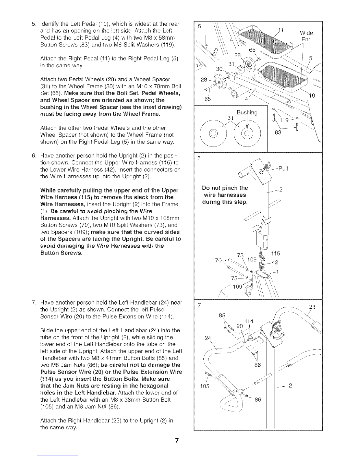
Identify the Left Pedal (10), which is widest at the rear
and has an opening on the left side. Attach the Left
Pedal to the Left Pedal Leg (4) with two M8 x 58mm
Button Screws (83) and two M8 Split Washers (119).
Attach the Right Pedal (11) to the Right Pedal Leg (5)
in the same way.
Attach two Pedal Wheels (28) and a Wheel Spacer
(31) to the Wheel Frame (30) with an M10 x 78mm Bolt
Set (65). Make sure that the Bott Set, Pedal Wheets,
and Wheel Spacer are oriented as shown; the
bushing in the WheeJ Spacer (see the inset drawing)
must be facing away from the WheeJ Frame.
65
Bushing
11
Wide
End
Attach the other two Pedal Wheels and the other
Wheel Spacer (not shown) to the Wheel Frame (not
shown) on the Right Pedal Leg (5) in the same way.
Have another person hold the Upright (2) inthe posi=
tion shown. Connect the Upper Wire Harness (115) to
the Lower Wire Harness (42). Insert the connectors on
the Wire Harnesses up into the Upright (2).
While carefully pulling the upper end of the Upper
Wire Harness (115) to remove the stack from the
Wire Harnesses, insert the Upright (2) into the Frame
(1). Be careful to avoid pinching the Wire
Harnesses. Attach the Upright with two M10 x 108mm
Button Screws (70), two M10 Split Washers (73), and
two Spacers (109); make sure that the curved sides
of the Spacers are facing the Upright. Be careful to
avoid damaging the Wire Harnesses with the
Button Screws.
83
6
Do not pinch the
wire harnesses
during this step.
73
Have another person hold the Left Handlebar (24) near
the Upright (2) as shown. Connect the left Pulse
Sensor Wire (20) to the Pulse Extension Wire (114).
Slide the upper end of the Left Handlebar (24) into the
tube on the front of the Upright (2), while sliding the
lower end of the Left Handlebar onto the tube on the
left side of the Upright. Attach the upper end of the Left
Handlebar with two M8 x 41 mm Button Bolts (85) and
two M8 Jam Nuts (86); be careful not to damage the
Pulse Sensor Wire (20) or the Pulse Extension Wire
(114) as you insert the Button Bolts. Make sure
that the Jam Nuts are resting in the he×agonal
holes in the Left HandJebar. Attach the lower end of
the Left Handlebar with an M8 x 38mm Button Bolt
(105) and an M8 Jam Nut (86).
Attach the Right Handlebar (23) to the Upright (2) in
the same way.
23
85
114
86
105
86
7
Page 8
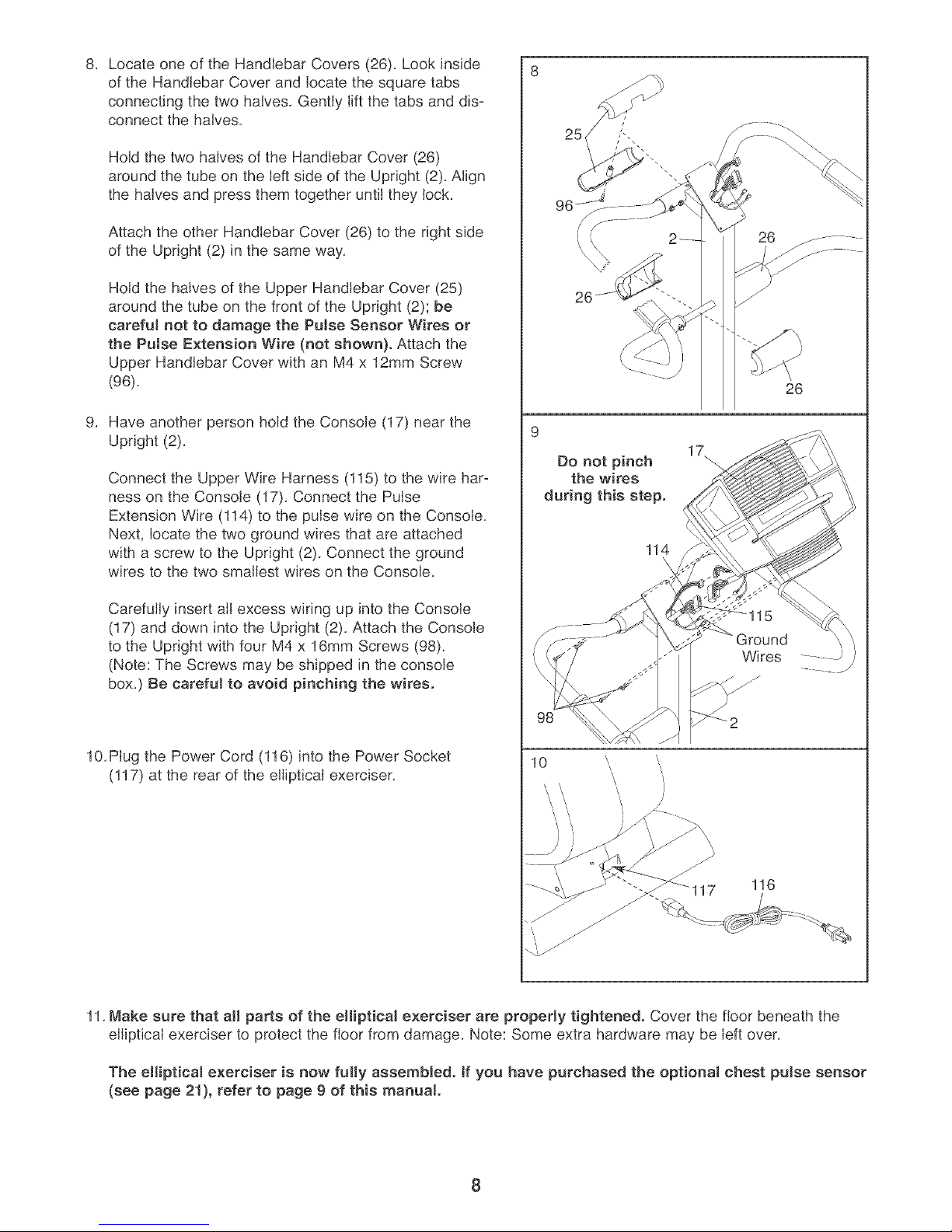
LocateoneoftheHandlebarCovers(26),Lookinside
8, 8
oftheHandlebarCoverandlocatethesquaretabs
connectingthetwohalves,Gentlyliftthetabsanddis-
connectthehalves,
HoldthetwohalvesoftheHandlebarCover(26)
aroundthetubeontheleftsideoftheUpright(2),Align
thehalvesandpressthemtogetheruntiltheylock,
AttachtheotherHandlebarCover(26)totherightside
oftheUpright(2)inthesameway,
HoldthehalvesoftheUpperHandlebarCover(25)
aroundthetubeonthefrontoftheUpright(2);be
carefulnotto damagethe Pulse Sensor Wires or
the Putse Extension WEre (not shown). Attach the
Upper Handlebar Cover with an M4 x 12mm Screw
(96),
Have another person hold the Console (17) near the
Upright (2),
Connect the Upper Wire Harness (115) to the wire har-
ness on the Console (17), Connect the Pulse
Extension Wire (114) to the pulse wire on the Console,
Next, locate the two ground wires that are attached
with a screw to the Upright (2) Connect the ground
wires to the two smallest wires on the Console,
Carefully insert all excess wiring up into the Console
(17) and down into the Upright (2) Attach the Console
to the Upright with four M4 x 16mm Screws (98),
(Note: The Screws may be shipped in the console
box,) Be careful to avoid pinching the wires.
26
9
Do not pinch
the wires
during this step.
114
26
/ ..........
/ ...........
26
\
Wires .........J )
/
\
10, Plug the Power Cord (116) into the Power Socket
(117) at the rear of the elliptical exerciser,
11, Make sure that all pa_s of the elliptical exerciser are properly tightened. Cover the floor beneath the
elliptical exerciser to protect the floor from damage, Note: Some extra hardware may be left over,
The elliptical exerciser is now fuJly assembled, tf you have purchased the optional chest pulse sensor
(see page 21), refer to page 9 of this manual
Page 9
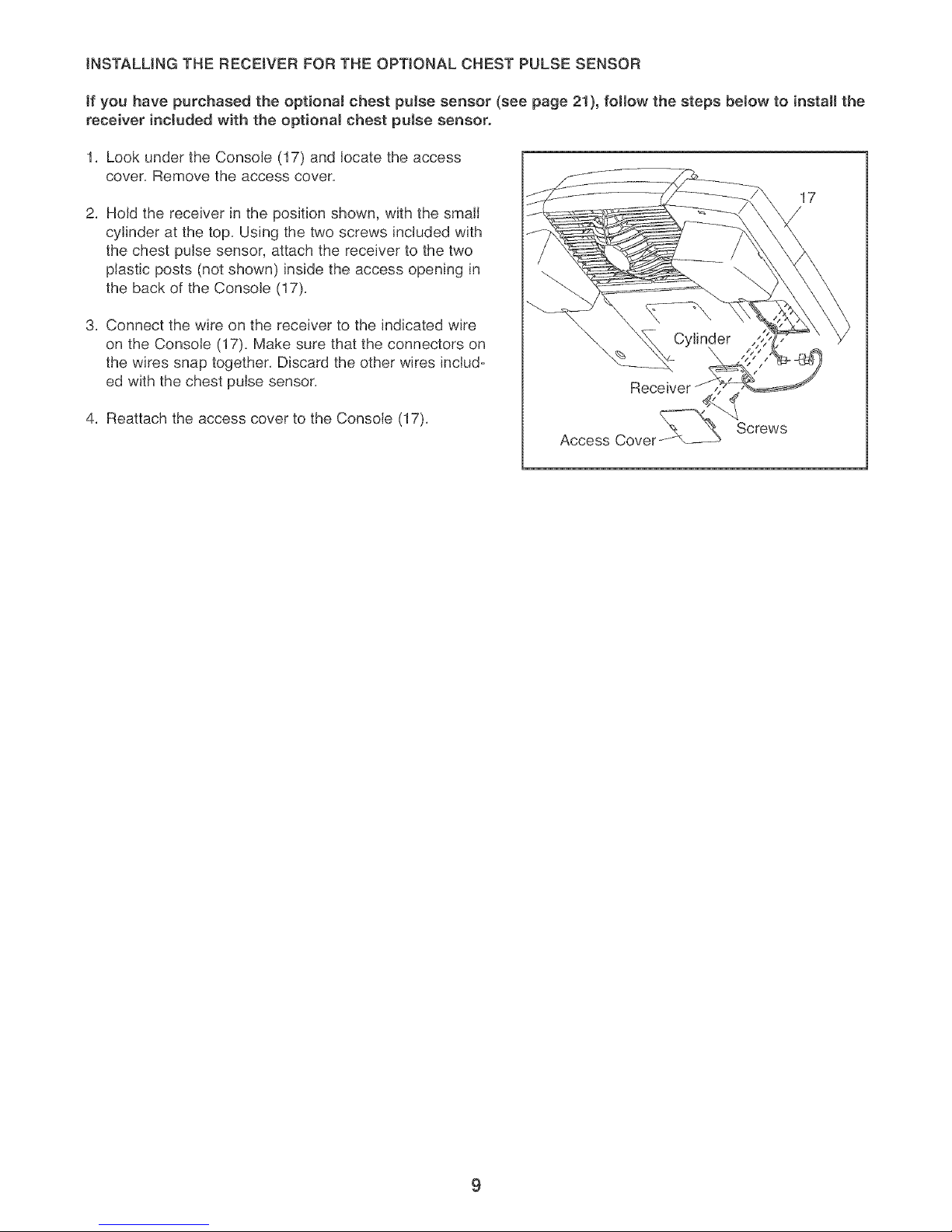
INSTALLINGTHE RECEIVER FOR THE OPTIONAL CHEST PULSE SENSOR
tf you have purchased the optionaJ chest puJse sensor (see page 21), fotlow the steps below to install the
receiver included with the optional chest pulse sensor.
1. Look under the Console (17) and locate the access
cover. Remove the access cover.
17
2. Hold the receiver in the position shown, with the small
cylinder at the top. Using the two screws included with
the chest pulse sensor, attach the receiver to the two
plastic posts (not shown) inside the access opening in
the back of the Console (17).
3. Connect the wire on the receiver to the indicated wire
on the Console (17). Make sure that the connectors on
the wires snap together. Discard the other wires includ-
ed with the chest pulse sensor.
4. Reattach the access cover to the Console (17).
Access Cover
Screws
9
Page 10

HOW TO USE THE ELLiPTiCAL EXERCISER
HOW TO PLUG tN THE POWER CORD
This product
must be
grounded.
If it should
malfunction
or break
down,
grounding
provides a
path of least
resistance for
electric
current to reduce the risk of electric shock. This prod-
uct is equipped with a cord having an equipment-
grounding conductor and a grounding plug. Plug the
power cord into an appropriate outlet that is prop=
edy installed and grounded in accordance with all
tocaJ codes and ordinances. This product is for
use on a nominaJ 120=volt circuit. Important: The
eHipticaJ exerciser is not compatible with GFCl-
equipped outlets.
Grounding Pin
Grounded Outlet
Outlet Box
Grounding Plug
The green-colored rigid ear, lug, or the like extending
from the adapter must be connected to a permanent
ground such as a properly grounded outlet box cover.
Whenever the adapter is used, it must be held in
place by a metal screw. Some 2-pote receptacle out-
tet box covers are not grounded. Contact a quali-
fied electrician to determine if the outJet box cover
is grounded before using an adapter.
Note: When the power cord is pJugged in, the chip=
tical exerciser's incline system may automatically
caJibrate itseff. During the caJibration process, two
dashes (- -) will appear in the left dispJay of the
console and the ramp will move to the highest
position and then return to the lowest position.
The calibration process will last for one to two
minutes.
EXERCISING ON THE ELUPTICAL EXERCISER
To mount the elliptical exerciser, hold the handlebars
and step onto the pedal that is in the lowest position.
Next, step onto the other pedal. Push the pedals until
they begin to move with a continuous motion.
DANG ER: Improperconnectionof
the equipment-grounding conductor can result
in an increased risk of eJeetric shock. Check
with a qualified eJectrician or serviceman if
you are in doubt as to whether the product is
properly grounded. Do not modify the plug
provided with the product--if it will not fit the
outlet, have a proper outlet installed by a qual-
ified electNcian.
A temporary
adapter may Outlet Box
be used to
connect the
power cord
to a 2=pole
receptacle
as shown at
the right if a Lug
properly Metal Screw
grounded
outlet is not
available. The temporary adapter should be used only
until a properly grounded outlet can be installed by a
qualified electrician.
man_
To dismount the elliptical exerciser, wait until the ped=
als come to a complete stop. The elliptical exerciser
does not have a free wheel; the pedaJs will contin=
ue to move until the flywheel stops. When the ped-
als are stationary, step off the highest pedal first.
Then, step off the lowest pedal.
10
Page 11

CONSOLE DIAGRAM Left Display Matrix Training Zone Bar
FEATURES OF THE CONSOLE
The advanced console offers a selection of features
designed to make your workouts more enjoyable and
effective. When the manual mode of the console is
selected, the resistance of the elliptical exerciser and
the angle of the ramp can be changed with the touch
of a button. As you exercise, the console will provide
continuous exercise feedback. You can even measure
your heart rate using the handgrip pulse sensor. Note:
For information about an optional chest pulse sen-
sor, see page 21.
The console also offers six resistance and pace pro=
grams. Each program automatically changes the resis-
tance of the elliptical exerciser and prompts you to
increase or decrease your pace as it guides you
through an effective workout.
In addition, the console features two heart rate pro-
grams that automatically change the resistance of the
elliptical exerciser and prompt you to vary your pace to
keep your heart rate near a target level as you exer-
cise.
The console also features iFIT.com interactive technol-
ogy. Having iFIT.com technology is like having a per=
sonal trainer in your home. Using the included audio
cable, you can connect the elliptical exerciser to your
home stereo, portable stereo, computer, or VCR and
play special iFIT.com CD and video programs (iFIT.com
CDs and videocassettes are available separately).
iFIT.com CD and video programs automatically control
the resistance of the elliptical exerciser and prompt
you to vary your pace as a personal trainer coaches
you through every step of your workout. High-energy
music provides added motivation. To purchase
iFJT.com CDs and videocassettes, call the toHofree
telephone number on the front cover of this manual
With the elliptical exerciser connected to your comput-
er, you can also go to our Web site at www iFIT.com
and access programs directly from the intemet.
Explore www.iFIT.com for more information.
11
Page 12

.owToUSET"EMA"UALMODE
Press any button on the console or begin
pedaling to turn on the console.
Make sure that the power cord is properly
plugged in (see page 10), Next, press any button
on the console or begin pedaling to turn on the
console, After a few seconds, the console dis-
plays will light, A tone will then sound and the
console will be ready for use,
Select the manual mode.
Monitor your progress with the matrix, the
Training Zone bar, and the two displays.
When the manual
mode or the
iFIT,com mode is
The matrix-- I
selected, the matrix
will show a track
representing 1/4
mile, As you exercise, the indicators around the
track will light, one at a time, until the entire track
is lit, When you have completed a lap, a new lap
will begin,
]
When the power is
turned on, the
manual mode will
be selected. If you
have selected a
program or the
iFIT.com mode,
select the manual mode by pressing the Program
Select button repeatedly until a track appears in
the matrix,
Begin pedaling and change the resistance of
the elliptical exerciser as desired.
change the resis- _ SPEED_ HEARTRATE
tance of the ellipti-
cal exerciser by
pressing the FAT _ CALS, _ RESISTANCE
Resistance but-
tons, There are
ten resistance levels, Note: After the Resistance
buttons are pressed, it will take a moment for the
elliptical exerciser to reach the selected resis-
tance level,
Adjust the angle of the ramp as desired.
As you pedal,
change the angle
of the ramp by
pressing the
Ramp buttons,
There are five
ramp angles,
Note: After the Ramp buttons are pressed, it will
take a moment for the ramp to reach the select-
ed angle,
'-:,
The Training Zone
bar--The Training
Zone bar will show
your pace and the
approximate inten-
sity level of your
exercise, For exam-
pie, if three or four indicators in the bar are lit, the
bar shows that your pace is ideal for fat burning,
During programs, the Training Zone bar will also
prompt you to increase or decrease your pace,
The left display--
The left display will
show the elapsed
time, the angle of
the ramp, and the
distance you have
pedaled, The dis-
play will change from one number to the next
every few seconds, as shown by the indicators
around the display, Note: When a program is
selected, the display will show the time remaining
in the program and the time remaining in the cur-
rent segment of the program instead of the
elapsed time,
The right
display--The right
display will show
your pedaling
speed, the approxi-
mate numbers of
fat calories and
calories you have burned (see FAT BURNING on
page 23), and the resistance level of the elliptical
exerciser, The display will change from one num-
ber to the next every few seconds, as shown by
the indicators around the display, The display will
also show your heart rate when you use the
handgnp pulse sensor or the optional chest pulse
sensor,
l _ SPEED _ HEART RATE
_ F/_:T _ CALS _ RESIST
" , ANCE
12
Page 13

Note: The console
can display speed
and distance in
either miles or kilo-
meters. To find
which unit of mea-
surement is select-
ed, you must select the console's user mode. Hold
down the Program Select button for about three
seconds. The letter "E" for English miles or the let-
ter "M" for metric kilometers will appear in the left
display. To change the unit of measurement, press
the + button.
While the user
mode is selected,
press the Program
Start button. The
left display will
then show the total
number of hours
that the elliptical exerciser has been used. Press
the Program Start button again. The left display
will then show the total number of miles pedaled.
To exit the user mode, press the Program Select
button again.
Measure your heart rate if desired.
Note: tf you hold the handgrip pulse sensor
and wear the optional chest pulse sensor at
the same time, the console may not display
your heart rate accurate[yo
If there are
thin sheets of
plastic on the
rneta[ con =
tacts on the
handgrip
pulse sensor,
peeJ off the
plastic. To Contacts
measure your
heart rate,
hold the con-
tacts; your palms must be resting on the upper
contacts, and your fingers must be touching the
lower contacts. Avoid moving your hands.
When your pulse is
detected, the Heart
Rate indicator
above the right dis-
play will begin to
flash, one or two
dashes (--) will
appear in the right display, and then your heart rate
will be shown. For the most accurate heart rate
reading, hold the contacts for at least 15 seconds.
Note: If you continue to hold the pulse sensor, the
right display will show your heart rate for up to 30
seconds. The display will then show your heart
rate along with the other modes.
If your heart rate is not shown, make sure that
your hands are positioned as described. Be care-
ful not to move your hands excessively or to
squeeze the metal contacts too tightly. For opti-
ma[ performance, clean the metal contacts using
a soft cloth; never use alcohol, abrasives, or
chemicals.
Turn on the fan if desired.
To turn on the fan at low speed, press the Fan
button. Pivot the fan to the desired angle. To turn
on the fan at high speed, press the Fan button a
second time. To turn off the fan, press the Fan
button a third time.
When you are finished exercising, the console
automatically turn off.
If the pedals are not moved for several seconds, a
tone will sound, the console will pause, and the
left display will begin to flash.
If the pedals are not moved for about five min-
utes, the console will turn off and the displays will
be reset.
13
Page 14

HOWTO USE RESISTANCE AND PACE
PROGRAMS
Press any button on the console or begin
pedaling to turn on the consote.
See step 1 on page 12.
Select one of the six resistance and pace
programs.
When the power is
turned on, the
manual mode will
be selected. To
select a resistance
and pace program,
press the Program
Select button repeatedly until a "P 1," "P 2," "P 3,"
"P 4," "P 5," or "P 6" appears in the right display.
When a resistance and pace program is selected,
the matrix will show the first seven pace settings
for the program. The left display will show how
long the program will last.
Press the Program Start button or begin
pedaling to start the program.
Each program is divided into several time seg-
ments of different lengths. One pace setting and
one resistance setting are programmed for each
segment. (The same pace setting and/or resis-
tance setting may be programmed for two or more
consecutive segments.)
setting for the cur-
rent segment. The
lit indicators in the _CE
bar will show your
actual pace. If an
indicator to the
right of the lit indi-
cators is flashing
(see drawing a), _cE
increase your pace.
If an indicator to
the left of any lit
indicator is flashing
(see drawing b), decrease your pace. When no
indicator is flashing, your pace matches the pace
setting for the current segment, important: The
pace settings are intended only to provide
motivation. Your actuaJ pace may be slower
than the current pace setting. Make sure to
exercise at a pace that is comfortable for you.
When only three seconds remain in the first seg-
ment of the program, both the Current Segment
column and the column to the right will flash, a
series of tones will sound, and all pace settings
will move one column to the left. The pace setting
for the second segment will then be shown in the
flashing Current Segment column and the resis-
tance of the elliptical exerciser will automatically
change to the resistance setting for the second
segment.
Note: If all of the indicators in the Current Segment
column are lit after the pace settings have moved
to the left, the pace settings will move downward
so that only the highest indicators appear in the
matrix.
The pace setting
for the first seg-
ment will be
shown in the flash-
ing Current
Segment column
of the matrix. (The
resistance settings
are not shown in the matrix.) The pace settings
for the next several segments will be shown in the
columns to the right.
As you exercise, the Training Zone bar will help
you to keep your pedaling pace near the pace
Current Segment
The program will continue until the pace setting
for the last segment is shown in the Current
Segment column of the matrix and no time
remains in the program.
Note: During the program, you can override the
resistance setting for the current segment, if
desired, by pressing the Resistance buttons.
However, when the next segment begins, the
resistance will automatically change if a different
resistance is programmed for the next segment. If
you stop pedaling for several seconds, a tone will
sound and the program will pause. To restart the
program, simply resume pedaling.
14
Page 15

Adjust the angte of the ramp as desired.
See step 4 on page 12.
Monitor your progress with the two displays.
See step 5 on page 12.
Measure your heart rate if desired.
See step 6 on page 13.
Turn on the fan if desired.
HOW TO USE HEART RATE PROGRAMS
Each heart rate program helps you to keep your heart
rate near a certain percentage of your maximum heart
rate during your workout. (Your maximum heart rate is
estimated by subtracting your age from 220. For
example, if you are 30 years old, your maximum heart
rate is 190.) Heart rate program 1 is designed to keep
your heart rate between 50% and 80% of your maxi-
mum heart rate while you exercise; heart rate pro=
gram 2 is designed to keep your heart rate between
50% and 85% of your maximum heart rate.
See step 7 on page 13.
When the program is finished, the consoJe
will automatically turn off.
See step 8 on page 13.
Follow the steps below to use a heart rate program.
Press any button on the console or begin
pedaling to turn on the console.
See step 1 on page 12.
Select one of the heart rate programs.
When the power is
turned on, the man-
ual mode will be
selected. To select
a heart rate pro=
gram, press the
Program Select
button repeatedly until an "H 1" or "H 2" appears
in the right display.
Enter your age.
When a heart rate
program is select-
TIME _ SEGMENT TIME
ed, the word "AGE"
and the current
age setting will
RAMP _ DISTANCE
flash in the left dis=
play. You must
enter your age to use a heart rate program. If
you have already entered your age, press the
Age Set Enter button and go to step 4. If you
have not entered your age, press the + or - but-
ton repeatedly to enter your age, and then press
the Age Set Enter button.
t
Once you have entered your age, it will be saved
in memory.
15
Page 16

HoJd the handgrip puJse sensor.
To use a heart rate program, you must use the
handgdp pulse sensor (see step 6 on page 13)
or the optional chest puJse sensor. If you use the
handgdp pulse sensor, it is not necessary to hold
the handgdps contJnuousJy during the program.
However, you should hold the handgdps fre-
quently for the program to operate properJy. Each
time you hold the handgdps, keep your hands
on the metaJ contacts for at Jeast 30 seconds.
Note: When you are not hoJding the handgdps,
the letters "PLS" wJil appear in the right display
instead of your heart rate.
Press the Program Start button or begin
pedaling to start the program.
Each heart rate program consists of 20 one-
minute segments. One resistance setting and
one heart rate setting are programmed for each
segment. (The same resistance setting and!or
heart rate setting may be programmed for two or
more consecutive segments.)
odicaJly compare
your heart rate to
the heart rate set-
ting for the current
segmentl if neces-
sary, an indicator
in the bar will then
flash to prompt you
to increase or _cE
decrease your
pace to bring your
heart rate closer to
the current heart
rate setting. If an indicator to the right of the Jit
indicators is flashing (see drawing a), increase
your pace. If an indicator to the left of any lit indi-
cator is flashing (see drawing b), decrease your
pace. When no indicator is flashing, your heart
rate is near the current heart rate setting.
Important: The heart rate settings are intend-
ed only to provide motivation. Your actual
heart rate may be slower than the current
heart rate setting. Make sure to exercise at a
pace that is comfortable for you.
The resistance
setting for the first Current Segment
segment will be
shown in the flash-
ing Current
Segment column
of the matrix. The
resistance settings
for the next several segments will be shown in the
columns to the right.
When onJy three seconds remain in the first seg-
ment of the program, both the Current Segment
column and the column to the right wiJJflash, a
series of tones will sound, and all resistance set-
tings will move one column to the left. The resis-
tance setting for the second segment will then be
shown in the flashing Current Segment column
and the resistance of the elJiptica} exerciser wilJ
automatically adjust to the resistance setting for
the second segment.
As you exercise, the Training Zone bar will help
you to keep your heart rate near the heart rate
setting for the current segment. The lit indicators
in the bar will show your actual pace. When you
hold the handgrip pulse sensor or wear the
optionaJ chest puJse sensor, the console wiJJperi-
The program wiJJcontinue untJJthe resistance set-
ting for the last segment is shown in the Current
Segment column of the matrix and no time
remains in the program.
Note: During the program, you can manuaJJy over-
ride the resistance setting for the current seg-
ment, if desired, with the Resistance buttons.
However, when the next segment begins, the
eiJiptical exerciser wiJl automatically adjust to the
resistance setting for the next segment. If you
stop pedaling for several seconds, a tone wiJl
sound and the program wiJJpause. To restart the
program, simply resume pedaJing.
Monitor your progress with the two dispJays.
See step 5 on page 12.
Turn on the fan if desired.
See step 7 on page 13.
When the program is finished, the consote
will automaticaJly turn off.
See step 8 on page 13.
16
Page 17

HOW TO CONNECT YOUR CD PLAYER, VCR,
OR COMPUTER
To use iFtT.com CDs, the elliptical exerciser must be
connected to your portable CD player, portable stereo,
home stereo, or computer with CD player. See pages
17 and 18 for connecting instructions. To use iFIT.com
videocassettes, the elliptical exerciser must be con-
nected to your VCR See page 19 for connecting
instructions. To use iFJTocom programs directly from
our Web site, the elliptical exerciser must be connect-
ed to your home computer. See page 18 for connect-
ing instructions.
HOW TO CONNECT YOUR PORTABLE CD PLAYER
Note: If your CD pJayer has separate LiNE OUT and
PHONES jacks, see instruction A be[ow, tf your CD
player has onJy one jack, see instruction Bo
A. Plug one end of the audio cable into the jack
beneath the console. Plug the other end of the
cable into the LINE OUT jack on your CD player.
Plug your headphones into the PHONES jack.
A
HOW TO CONNECT YOUR PORTABLE STEREO
Note: ff your stereo has an RCA-type AUDIO OUT
jack, see instruction A below, ff your stereo has a
1/8" LINE OUT jack, see instruction B. If your
stereo has only a PHONES jack, see instruction C.
A. Plug one end of the audio cable into the jack
beneath the console. Plug the other end of the cable
into the adapter. Plug the adapter into an AUDIO
OUT jack on your stereo.
Adapter
Audio Cable
B,
Plug one end of the audio cable into the jack
beneath the console. Plug the other end of the
cable into the LINE OUT jack on your stereo. Do
not use the adapter.
B. Plug one end of the audio cable into the jack
beneath the console. Plug the other end of the
cable into a 1/8" Y-adapter (available at electronics
stores). Plug the Y-adapter into the PHONES jack
on your CD player. Plug your headphones into the
other side of the Y-adapter.
C,
Plug one end of the audio cable into the jack
beneath the console. Plug the other end of the
cable into a 1/8" Y-adapter (available at electronics
stores). Plug the Y-adapter into the PHONES jack
on your stereo. Plug your headphones into the
other side of the Y-adapter.
17
Page 18

HOW TO CONNECT YOUR HOME STEREO HOW TO CONNECT YOUR COMPUTER
Note: If your stereo has an unused LINE OUT jack,
see instruction A below. Jf the LINE OUT jack is
being used, see instruction B.
A, Plug one end of the audio cable into the jack
beneath the console, Plug the other end of the
cable into the adapter, Plug the adapter into the
LINE OUT jack on your stereo,
! u,EouT
u
Audio Adapter_
u............. _
Cable
B, Plug one end of the audio cable into the jack
beneath the console, Plug the other end of the
cable into the adapter, Plug the adapter into an
RCA Y-adapter (available at electronics stores),
Next, remove the wire that is currently plugged into
the LINE OUT jack on your stereo and plug the
wire into the unused side of the Y-adapter, Plug the
Y-adapter into the LINE OUT jack on your stereo,
Note: ff your computer has a 1/8" LiNE OUT jack,
see instruction A. If your computer has only a
PHONES jack, see instruction Bo
A, Plug one end of the audio cable into the jack
beneath the console, Plug the other end of the
cable into the LINE OUT jack on your computer,
i
=1
=1 ooo
B, Plug one end of the audio cable into the jack
beneath the console, Plug the other end of the
cable into a 1/8" Y-adapter (available at electronics
stores), Plug the Y-adapter into the PHONES jack
on your computer, Plug your headphones or speak-
ers into the other side of the Y-adapter,
Audio
Cable
Adapter
Wire removed from
LINE OUT jack
RCA
Y-adapter
Audio
Cable
1/8"
Y-adapter
Headphones/Speakers _
18
Page 19

HOW TO CONNECT YOUR VCR
Note: if your VCR has an unused AUDIO OUT jack,
see instruction A below, if the AUDIO OUT jack is
being used, see instruction B. If you have a TV
with a built-in VCR, see instruction B. If your VCR
is connected to your home stereo, see HOW TO
CONNECT YOUR HOME STEREO on page 18.
A, Plug one end of the audio cable into the jack
beneath the console, Plug the other end of the
cable into the adapter, Plug the adapter into the
AUDIO OUT jack on your VCR,
A
i.£i
B, Plug one end of the audio cable into the jack
beneath the console, Plug the other end of the
cable into the adapter, Plug the adapter into an
RCA Y-adapter (available at electronics stores),
Next, remove the wire that is currently plugged into
the AUDIO OUT jack on your VCR and plug the
wire into the unused side of the Y-adapter, Plug the
Y-adapter into the AUDIO OUT jack on your VCR,
Audio Cable Adapter
_ A a tit °"__°_ °
°°°
Audio Cable
..........
Wire removed from _c:_
AUDIO OUT jack
19
Page 20

HOW TO USE IFJT,COM CD AND VIDEO
PROGRAMS
To use iFIT,com CDs or videocassettes, the elliptical
exerciser must be connected to your portable CD play-
er, portable stereo, home stereo, computer with CD
player, or VCR. See HOW TO CONNECT YOUR CD
PLAYER, VCR, OR COMPUTER on page 17. To pur-
chase iFJT.com CDs and videocassettes, call toll-
free 1-800-735-0768.
your workout. Simply follow your personal trainer's
instructions.
The program will function in almost the same way
as a resistance and pace program (see step 3 on
page 14). However, an electronic "chirping" sound
will alert you when the resistance setting and/or
the pace setting is about to change.
Note: ff the resistance of the eHipticaJ exerciser
and/or the pace setting does not change when
a "chirp" is heard:
Follow the steps below to use an iFIT.com CD or
video program.
Press any button on the console or begin
pedaling to turn on the consoJe.
See step 1 on page 12.
Select the iFJT.com mode.
When the console
is turned on, the
manual mode will
be selected. To
select the iFIT.com
mode, press the
iFIT.com button.
The indicator above the button will light.
Insert the iFJTocom CD or videocassette.
If you are using an iFIT.com CD, insert the CD
into your CD player. If you are using an iFIT.com
videocassette, insert the videocassette into your
VCR.
Press the ptay button on your CD player or
VCR.
d
•Make sure that the indicator above the
iFIT.com button is lit.
•Adjust the volume of your CD ptayer or VCR.
tf the volume is too high or too low, the con-
sote may not detect the program signalso
•Make sure that the audio cable is properly
connected and that it is fully plugged in.
Monitor your progress with the two displays.
See step 5 on page 12.
Measure your heart rate if desired.
See step 6 on page 13.
Turn on the fan if desired.
See step 7 on page 13.
When the program is finished, the consote wHI
automatically turn off.
See step 8 on page 13.
A moment after the play button is pressed, your
personal trainer will begin guiding you through
2O
Page 21

HOW TO USE PROGRAMS DIRECTLY FROM
OUR WEB SiTE
Our Web site at www,iFIT,com allows you to play
iFIT.com audio and video programs directly from the
internet, To use programs from our Web site, the eJlip-
tical exerciser must be connected to your home com-
puter, See HOW TO CONNECT YOUR COMPUTER
on page 18, In addition, you must have an internet
connection and an internet service provider, A list of
specific system requirements is found on our Web
site,
Follow the steps below to use a program from our
Web site.
Return to the elliptical e×erciser and begin
pedaling.
When the on-screen countdown ends, the pro-
gram will begin. The program will function in
almost the same way as a resistance and pace
program (see step 3 on page 14). However, an
electronic "chirping" sound will alert you when the
resistance setting and/or the pace setting is about
to change.
Monitor your progress with the two dispJays.
See step 5 on page 12.
Measure your heart rate if desired.
Press any button on the console or begin
pedaling to turn on the consoJe.
See step 1 on page 12.
SeJect the iFJT.com mode.
When the console
is turned on, the
manual mode will
be selected. To
select the iFIT.com
mode, press the
iFJT.com button.
The indicator above the button will light.
Go to your computer and start an internet
connection.
Start your Web browser, if necessary, and go
to our Web site at www.iFIT.com.
Follow the desired links on our Web site to
select a program.
See step 6 on page 13.
Turn on the fan if desired.
See step 7 on page 13.
When you are finished exercising, the consote
automatically turn off.
See step 8 on page 13.
THE OPTIONAL CHEST PULSE SENSOR
The optional chest pulse sensor provides hands-free
operation and continuously monitors your heart rate
during your workouts. To purchase the optionaJ
chest pulse sensor, call toll-free 1=800-734-2377.
/
Read and follow the ondine instructions for using
a program.
Follow the on=line instructions to start the
program.
When you start the program, an on-screen count-
down will begin.
..... -::: ........
21
Page 22

MAINTENANCE AND TROUBLESHOOTING
Inspect and properly tighten all parts of the elliptical
exerciser regularly. Replace any worn parts immedi-
ately.
For smooth
operation of the Wheels
elliptical exer-
ciser, inspect
and clean the
incline ramp
reguJarly using Ramp
a soft cloth and
mild detergent.
Other parts of
the elliptical
exerciser can
also be cleaned in this way. Keep liquids off the
console. Never use abrasives or aoNenta.
PULSESENSOR TROUBLESHOOTING
If the handgrip pulse sensor does not function proper-
ly, see step 6 on page 13.
HOW TO CALIBRATE THE INCUNE SYSTEM
HOW TO MOVE THE ELUPTICAL EXERCISER
Stand in front of the elliptical exerciser, hold the han-
dlebars firmly, and place one foot against the ramp in
the location shown below. Pull the handlebars until
the elliptical exerciser can be moved on the front
wheels, and carefully move the elliptical exerciser to
the desired location. Then, place one foot against the
ramp, and lower the elliptical exerciser. Due to the
size and weight of the elliptic!l exerciser, use
extreme caution while moving and towering it.
Handlebars
If the elliptical exerciser's incline system is not working
properly, activate the calibration process by following
the steps below.
Hold down the + button and the Program Select
button at the same time for about five seconds.
Note: Numbers may appear in the left and right
displays. Disregard these numbers.
2. Press the Program Select button again Note: A
combination of letters and numbers may appear in
the displays.
3. Press the 30° Ramp button. The ramp will move all
of the way up and then all of the way down.
4. Press the Program Select button three times. The
console will then be in the normal operating mode
and the elliptical exerciser will be ready for use.
HOW TO LEVEL THE ELUPTtCAL EXERCISER
If the elliptical
exerciser rocks
during use, turn
one or both of
the leveling feet
under the rear
stabilizer until
the rocking
motion is elimi-
nated.
Leveling
Foot
22
Page 23

CONDiTiONiNG GUiDELiNES
WAF{NING:
Before beginning this or any exercise pro-
gram, consuJt your physician. This is espe-
eiaJly important for persons over the age of 35
or persona with pre-existing health problems.
During the first few minutes of exercise, your body
uses easily accessible carbohydrate calodes for ener-
gy. Only after the first few minutes of exercise does
your body begin to use stored fat calories for energy.
If your goal is to burn fat, adjust the intensity of your
exercise until your heart rate is near the lowest num-
ber in your training zone as you exercise.
The pulse sensor is not a medical device.
Various factors may affect the accuracy of
heart rate readings. The pulse sensor is
intended only as an exercise aid in determin-
ing heart rate trends in general.
The following guidelines will help you to plan your
exercise program. Remember that proper nutrition
and adequate rest are essential for successful results.
EXERCISE iNTENSiTY
Whether your goal is to burn fat or to strengthen your
cardiovascular system, the key to achieving the
desired results is to exercise with the proper intensity.
The proper intensity level can be found by using your
heart rate as a guide. The chart below shows recom-
mended heart rates for fat burning, maximum fat
burning, and cardiovascular (aerobic) exercise.
165 255 145 240 230 225 215 _
245 238 230 225 128 220 203 C_)
225 120 215 i20 105 95 90 _#
20 30 40 50 60 70 80
For maximum fat burning, adjust the intensity of your
exercise until your heart rate is near the middle num-
ber in your training zone as you exercise.
Aerobic Exercise
If your goal is to strengthen your cardiovascular sys-
tem, your exercise must be "aerobic." Aerobic exer-
cise is activity that requires large amounts of oxygen
for prolonged periods of time. This increases the
demand on the heart to pump blood to the muscles,
and on the lungs to oxygenate the blood. For aerobic
exercise, adjust the intensity of your exercise until
your heart rate is near the highest number in your
training zone as you exercise.
WORKOUT GUIDEMNES
Each workout should include the following three parts:
A warm-up, consisting of 5 to 10 minutes of stretching
and light exercise. A proper warm-up increases your
body temperature, heart rate, and circulation in prepa-
ration for exercise.
Training zone exercise, consisting of 20 to 30 min-
utes of exercising with your heart rate in your training
zone. (During the first few weeks of your exercise
program, do not keep your heart rate in your training
zone for longer than 20 minutes.)
To find the proper heart rate for you, first find your age
on the bottom line of the chart (ages are rounded off
to the nearest ten years). Next, find the three numbers
above your age. The three numbers are your "training
zone." The lower two numbers are recommended
heart rates for fat burning; the highest number is the
recommended heart rate for aerobic exercise.
Fat Burning
To burn fat effectively, you must exercise at a relative-
ly low intensity level for a sustained period of time.
A cooJ-down, with 5 to 10 minutes of stretching. This
will increase the flexibility of your muscles and will
help to prevent post-exercise problems.
EXERCISE FREQUENCY
To maintain or improve your condition, complete three
workouts each week, with at least one day of rest
between workouts. After a few months of regular exer-
cise, you may complete up to five workouts each week
if desired. The key to success is to make exercise a
regular and enjoyable part of your everyday life.
23
Page 24

PART LiST--Model No. NTE1192.1 Ro4osA
Key No. Qty. Description
1 1 Frame
2 1 Upright
3 1 Ramp
4 1 Left Pedal Leg
5 1 Right Pedal Leg
6 1 Rear Stabilizer
7 1 Rear Stabilizer Cover
8 1 Front Stabilizer
9 1 Front Stabilizer Cover
10 1 Left Pedal
11 1 Right Pedal
12 1 Incline Motor
13 1 IncJineAxle
14 1 Pivot Axle
15 1 Left Side Shield
16 1 Right Side Shield
17 1 Console
18 1 Right Flywheel Cover
19 1 Left Flywheel Cover
20 2 Pulse Sensor w/Wire
21 1 Right Incline Cover
22 1 Left IncJine Cover
23 1 Right Handlebar
24 1 Left Handlebar
25 1 Upper Handlebar Cover
26 2 Handlebar Cover
27 1 Frame Cover
28 4 Pedal WheeJ
29 8 WheeJ Bearing
30 2 Wheel Frame
31 2 Wheel Spacer
32 1 "C" Magnet
33 1 Magnet Bracket
34 1 Left Crank Arm
35 2 28,7mm Pulley Spacer
36 1 Flywheel
37 1 Magnet
38 1 PuJJey
39 1 Control Box Cover
40 1 Control Board
41 1 Control Box
42 1 Lower Wire Harness
43 1 Crank
44 2 Crank Bearing
45 1 Idler
46 4 Foot
47 4 Ramp Bushing
48 2 Ramp Cover
49 1 Incline Sensor
50 1 Sensor Cover
51 4 PedaJ Leg Bushing
52 1 Resistance Motor
53 1 Reed Switch Bracket
Key No.
54
55
56
57
58
59
6O
61
62
63
64
65
66
67
68
69
70
71
72
73
74
75
76
77
78
79
80
81
82
83
84
85
86
87
88
89
90
91
92
93
94
95
96
97
98
99
100
101
102
103
104
105
106
Qty.
1
1
1
1
1
1
2
2
2
2
2
2
2
2
2
10
2
1
1
2
1
1
8
4
4
4
2
1
2
4
8
4
6
8
3
1
3
2
2
2
3
6
1
2
15
2
4
2
1
1
2
2
2
Description
Clamp
Reed Switch/Wire
Return Spring
Guide Rod
Resistance Cable
Flywheel Axle
Flywheel Bearing
Eye Bolt
Adjustment Bracket
M8 x 47mm Button Bolt
M6 Washer
M10 x 78mm Bolt Set
M8 Washer
M10 x 50mm Bolt Set
Handlebar Bushing
M4 x 16mm Tek Screw
M10 x 110mm Button Screw
M8 Tek Washer
Mll x 40mm Bolt Set
M10 Split Washer
M8 x 25mm Button Bolt
M10 x 19mm Button Bolt
M6 x 16mm Patch Screw
M5 Nut
M5 x 16mm Bolt
M5 Washer
M6 x 18mm Bolt
M6 x 25mm Bolt
5/16" x 25mm Flange Screw
M8 x 58mm Button Screw
M8 x 44mm Button Screw
M8 x 41mm Button Bolt
M8 Jam Nut
M4 x 38mm Screw
M8 Nylon Locknut
M10 Nylon Locknut
M6 Nut
M6 Nylon Locknut
Snap Ring
M8 x 56mm Button Screw
M4 x 10mm Screw
M4 x 19mm Screw
M4 x 12mm Screw
M4 x 25mm Screw
M4 x 16mm Screw
Ramp Spacer
M5 Nylon Locknut
31,5mm PuJJeySpacer
Right Crank Arm
Flywheel Spacer
Support Plate
M8 x 38mm Button Bolt
Upper Foam Grip
24
Page 25

Key No. Qty. Description Key No. Qty. Description
107 2 Lower Foam Grip 115 1 Upper Wire Harness
108 3 M4 x 25mm Tek Screw 116 1 Power Cord
109 2 Spacer 117 1 Power Socket
110 6 Wheel Bushing 118 - (Not Used)
111 2 M8 x 19mm Patch Screw 119 4 M8 Split Washer
112 2 Wheel # 4 Allen Wrench
113 1 Belt # 1 User's Manual
114 1 Pulse Extension Wire
Note: # indicates a non-illustrated part, Specifications are subject to change without notice, See the back cover
of this manual for information about ordering replacement parts,
25
Page 26

EXPLODED DRAWING-- Modem No. NTE1192.1 Ro4osA
105
86 26
2O
1O8
114
g8
g8
69
98
69
\ \\ \
17
116
// 69
Page 27

,,,,q
76
65
76
48 14
110
3O
110
)29
28
47
28
76
67
47
65
_109
76
13
109
64
72
76
99
36
10
J
6O
35 101 y
34
51
95
93
35
11
I_77 79
52
98
_79
7
91
42
46
111
46
Page 28

HOW TO ORDER REPLACEMENT PARTS
To order replacement parts, see the front cover of this manual, To help us assist you, please be prepared to give
the foJJowing information:
• the MODEL NUMBER of the product (NTE1192,1)
• the NAME of the product (NordicTrack CX 985 elliptical exerciser)
• the SERIAL NUMBER of the product (see the front cover of this manual)
• the KEY NUMBER and DESCRIPTION of the part(s) (see pages 24 and 25)
LIMITED WARRANTY
WHAT IS COVERED--The entire NordicTrack _'elliptical exerciser ("Product") is warranted to be free of all defects in material and
workmanship.
WHO IS COVERED--The original purchaser or any person receiving the Product as a gift from the original purchaser.
HOW LONG IS IT COVERED--ICON Health & Fitness, Inc. ("ICON"), warrants the product for one year after the date of purchase.
Labor is covered for one year.
WHAT WE DO TO CORRECT COVERED DEFECTS--We will ship to you, without charge, any replacement part or component, pro-
viding the repairs are authorized by ICON first and are performed by an ICON trained and authorized service provider, or, at our
option, we will replace the Product.
WHAT IS NOT COVERED--Any failures or damage caused by unauthorized service, misuse, accident, negligence, improper assem-
bly or installation, alterations, modifications without our written authorization or by failure on your part to use, operate, and rnaintain
as set out in your User's Manual ("Manual").
WHAT YOU MUST DO--Always retain proof of purchase, such as your bill of sale; store, operate, and maintain the Product as spec-
ified in the Manual; notify our Customer Service Department of any defect within 10 days after discovery of the defect; as instruct-
ed, return any defected part for replacement or, if necessary, the entire product, for repair.
USER'S MANUAL--It is VERY IMPORTANT THAT YOU READ THE MANUAL before operating the Product. Remember to do the
periodic rnaintenance requirements specified in the Manual to assure proper operation and your continued satisfaction.
HOW TO GET PARTS AND SERVICE--Simply call the telephone number on the front cover of this manual and give your name and
address and the serial number of your Product. They will tell you how to get a part replaced, or, if necessary, arrange for service
where your Product is located or advise you how to ship your Product for service. Before shipping, always obtain a Return
Authorization Number (RA No.) from our Customer Service Department; securely pack your Product (save the original shipping car-
ton if possible); put the RA No. on the outside of the carton and insure the product. Include a letter explaining the product or prob-
lem and a copy of your proof of purchase if you believe the service is covered by warranty.
ICON is not responsible or liable for indirect, special or consequential damages arising out of or in connection with the use or per-
formance of the product or damages with respect to any economic loss, loss of property, loss of revenues or profits, loss of enjoy-
rnent or use, costs of removal, installation or other consequential damages of whatsoever nature. Some states do not allow the exclu-
sion or limitation of incidental or consequential damages. Accordingly, the above limitation may not apply to you.
The warranty extended hereunder is in lieu of any and all other warranties and any implied warranties of merchantability or fitness
for a particular purpose is limited in its scope and duration to the terms set forth herein. Some states do not allow limitations on how
long an implied warranty lasts. Accordingly, the above limitation may not apply to you.
No one is authorized to change, modify or extend the terms of this limited warranty. This warranty gives you specific legal rights and
you rnay have other rights which vary from state to state.
iCON HEALTH & FITNESS, iNC., 1500 S. 1000 W., LOGAN, UT 84321=9813
Part No, 203262 R0405A Printed in China @2004 ICON IP, Inc,
 Loading...