

Page 1
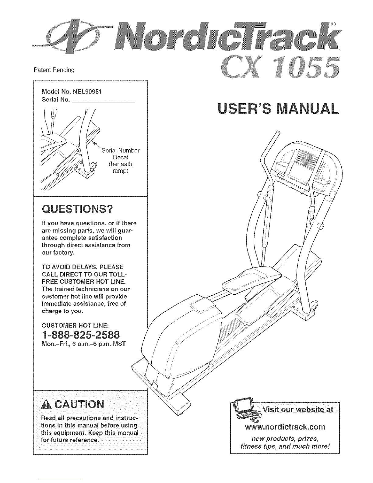
ModelNo.NEL90951
SerialNo.
Number
DecaU
(beneath
ramp)
QUESTIONS?
if you have questions, or if there
are missing parts, we wilt guar-
antee comptete satisfaction
through direct assistance from
our factory.
TO AVOID DELAYS, PLEASE
CALL DIRECT TO OUR TOLL-
FREE CUSTOMER NOT LINE.
The trained technicians on our
customer hot tine will provide
immediate assistance, free of
charge to you.
CUSTOMER HOT LINE:
1°888°825°2588
Mon.=Fri., 6 a.m.=6 p.m. NST
_k CAUTmON
m
ourwebsiteat
www.nordictrack.com
new products, prizes,
fitness tips, and much more r.
Page 2

JJ
TABLE OF CONTENTS
iMPORTANT PRECAUTIONS ................................................................ 3
BEFORE YOU BEGIN ...................................................................... 4
ASSEMBLY ............................................................................... 5
HOW TO USE THE ELLHPTHCALEXERCHSER ................................................... 9
MAHNTENANCE AND TROUBLESHOOTHNG ................................................... 21
CONDHTHONHNGGUHDELHNES............................................................... 22
PART LiST .............................................................................. 25
EXPLODED DRAWHNG .................................................................... 26
HOW TO ORDER REPLACEMENT PARTS ............................................. Back Cover
LHMHTEDWARRANTY .............................................................. Back Cover
NordicTrack is a registered trademark of HCON HP,Hnc,
2
Page 3

iMPORTANT PRECAUTIONS
A WARNING. Toreducether,skofeer,ous,njury,readthefo,owingimportantprecau-
tionsbefore using the elliptical exerciser.
1. Read all instructions in this manual before 10. Keep your back straight when using the eHip=
using the elliptical exerciser, tieai exerciser; do not arch your back.
2. it is the responsibility of the owner to ensure
that aH users of the eHipticaJ exerciser are
adequately informed of all precautions.
3. The eJHpticaJ exerciser is intended for 12. The pulse sensor is not a medical device.
in-home use only. Do not use the eHipticaJ Various factors, including the user's move°
exerciser in a commercial, rental, or inetituo merit, may affect the accuracy of heart rate
tionaJ setting, readings. The pulse sensor is intended onty
4. PJace the elliptical exerciser on a level sur- trends in general
face. with a mat beneath it to protect the
floor or carpet. Keep the elliptical exerciser 13. When you stop exercising, allow the pedals
indoors, away from moisture and dust. to eJowly come to a complete stop. The eJlip=
5. inspect and property tighten aH parts regu- the pedals will continue to move until the
larJy. Replace any worn parts immediately, flywheeJ stops.
6. Keep children under age 12 and pets away
from the eili ptical exerciser at aHtimes.
7. The elliptical exerciser shouJd not be used
by persons weighing more than 300 pounds.
8. Wear appropriate exercise clothes when
using the elliptical exerciser. Always wear
athletic shoes for foot protection.
9. AJwaye hold the handlebars when mounting,
dismounting, or using the eHipticaJ exerciser.
11. if you feel pain or dizziness while exercis-
ing, stop immediately and begin cooling
down.
as an exercise aid in determining heart rate
tical exerciser does not have a free wheel;
14. Always unplug the power cord immediately
after use and before cleaning the elliptical
exerciser.
15. The decals shown on page 4 have been
placed on the elliptical exerci set. mfeither
decaJ is missing or illegible, please caJl our
Customer Service Department toll=free at
1-666=625-2586 and order a free replacement
decal Apply the decal in the Jocation shown.
_k WARN iNG: Beforebeginningtheeoranyexercieeprogram,cone._tyourphye_e_an.
This is especially important for persons over the age of 35 or persons with pro=existing heaJth prob°
lens. Read aH instructions before using, iCON assumes no responsibility for personal injury or
property damage sustained by or through the use of this product.
3
Page 4
BEFORE YOU BEGIN
Congratulations for selecting the new NordicTrack _
CX 1055 elliptical exerciser, The CX 1055 elliptical
exerciser is an incredibly smooth exerciser that moves
your feet in a natural elliptical path, minimizing the
impact on your knees and ankles, And the unique CX
1055 elliptical exerciser features adjustable resistance
and incline to help you get the most from your exercise,
For your benefit, read this manua_ carefully before
you use the elliptical exerciser, if you have ques-
tions after reading the manual, please call our
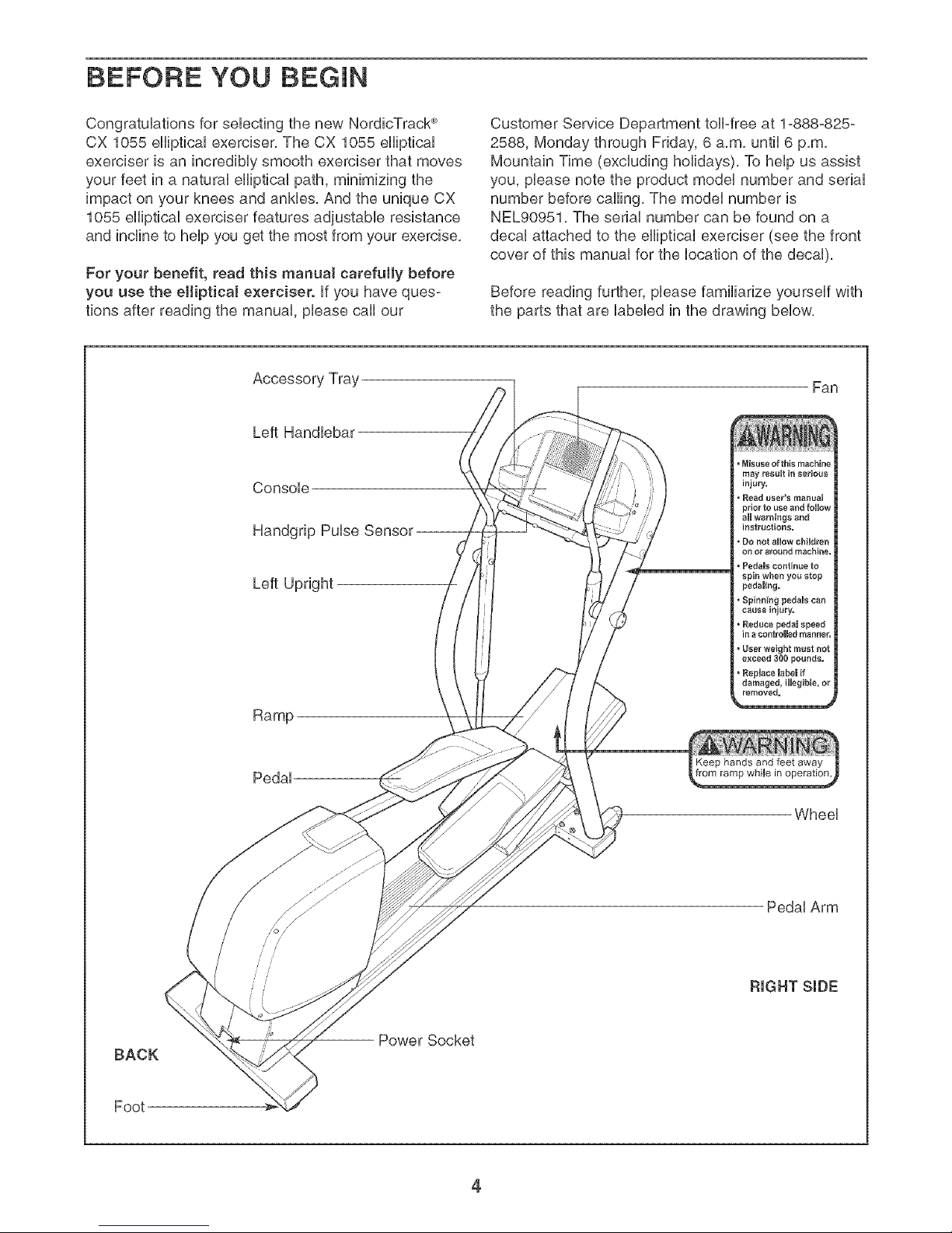
Accessory Tray
Left Handlebar
Console
Handgrip Pulse
Left Upright
Ramp
Customer Service Department toll-free at 1-888-825-
2588, Monday through Friday, 6 a,m, until 6 p,m,
Mountain Time (excluding holidays), To help us assist
you, please note the product model number and serial
number before calling, The model number is
NEL90951, The serial number can be found on a
decal attached to the elliptical exerciser (see the front
cover of this manual for the location of the decal),
Before reading further, please familiarize yourself with
the parts that are labeled in the drawing below,
Fan
°Misuse of this machine
may _esult in serious
injury,
• Read useds manual
prior to use and follow
aimwarnings and
instructions.
Do not allow children
on or around machine,
• Pedals continue to
spin when you stop
pedaling.
, Spinning pedals can
cause injury,
• Reduce pedal speed
ina control_d mannes
• User weight must not
exceed 300 pounds,
• ReplaceRabemif
damaged, illegible, or
removed,
Pedal
BACK
Foot
Wheel
Pedal Arm
RIGHT SiDE
-- Power Socket
4
Page 5

AssemMy requires two persons. PHaceaHHparts of the eHHpticaHexerciser in a cHeared area and remove the
packing materiaHs, Do not dispose of the packing materiaHs until assembHy is compHeted, In addition to the two
included he× keys, assembJy requires a phillips screwdriver _- _, two adjustable
wrenches _/_>, a rubber mattet r: ---_;; _i_i , and pliers .
Use the drawings bellow to identify the smaHHparts used for assembHy, The number in parenthesis bellow each
drawing is the key number of the part, from the PART LHSTon page 25, The number foHHowingthe key number is
the quantity needed for assembHy, Note: Some small parts may have been pre-assembted. If a part is not in
the parts bag, check to see if it has been pre-assembled.
"_. j
M8 Split
Washer M8 Washer Wave Washer
(101 )-12 (94)-6 (100)-2
M8 NyHon
Locknut (102)-12
M4 x 25mm
Screw (105)-4
M8 x 56mm Button Screw (108)-4 M8 x 68mm Button Screw (110)-8
M8 x 23mm FHat
Head Screw (88)-6
S \\\
\
M8 x 25mm
Washer (95)-2
M8 x 20mm Button
Screw (113)-2
M8 x 76mm Button BoHt(112)-4
y S\
/
\
M8 x 28mm
Washer (99)-4
M8 x 25mm Button
Screw (81)-2
\
Remove the Pivot Arms (not shown) and the pHastic
inserts from the Left and Right Uprights (4, 3), Hdentify
the Left Upright (4) and hoHdit near the Frame (1),
WhiHeanother person Hiltsthe Heftside of the eHHipticaH
exerciser, connect the Extension Wire Harness (76) to
the Lower Wire Harness (77),
Hnsertthe Left Upright (4) into the Frame (1), and
attach it with two M8 x 56mm Button Screws (108),
two M8 x 68mm Button Screws (110), and four M8
Split Washers (101); make sure not to pinch the
Wire Harnesses (76, 77). Tighten a Frame Cushion
(32) into the Frame (1) as indicated,
While another person lifts the right side of the Frame
(1), attach the Right Upright (3) to the Frame in the
same way, (Note: There are no wire harnesses on the
right side,) Tighten the other Frame Cushion (32) into
the other side of the Frame (1),
/
/
Do not pinch the
wire harnesses
during this step.
101
1
110
1 j
32
32
3
Page 6

HoUdthe ConsoUe Frame (6) near the Uprights (3, 4),
2, 2
Connect the Upper Wire Harness (75) to the Extension
Wire Harness (76), Attach the ConsoUe Frame to the
Uprights with four M8 x 76mm Button BoUts(112) and
four M8 NyUonLocknuts (102); make sure not to
pinch the Wire Harnesses.
112
\
SHde an M8 x 28mm Washer (99) onto an M8 x 20mm
Button Screw (113), Tighten the Button Screw into one
end of the UncHneAxUe(40), AppUya small amount of
the included grease to the UncHneAxUe,
Orient the UncHneRamp (5) so that the straight end is
in the position shown, HoUdthe weUded tube on the
bottom of the UncHneRamp between the two rings on
the top of the Frame, Unsertthe UncHneAxUe(40)
through the rings and the weUded tube,
Slide an M8 x 28mm Washer (99) onto an M8 x 20mm
Button Screw (113), Tighten the Button Screw into the
open end of the UncHneAxUe(40),
76
02
Do not pinch the
wire harnesses
during this step.
\,
\
I
!
/
/
/3
Using your fingers, turn the shaft on top of the Lift
Motor (42) counterclockwise until it stops turning,
Position the U-bracket on the bottom of the Incline
Ramp (5) over the end of the shaft as shown, Next,
hold an Incline Motor Spacer (60) on each side of the
shaft, between the shaft and the Uobracket,
Next, insert the Short CUevis Pin (118) through the U-
bracket on the Incline Ramp (5), the shaft on the Lift
Motor (42), and the two Incline Motor Spacers (60),
Insert the straight end of a Hairpin (71) into the end of
the Short Clevis Pin,
113
99
Front View
6
Page 7
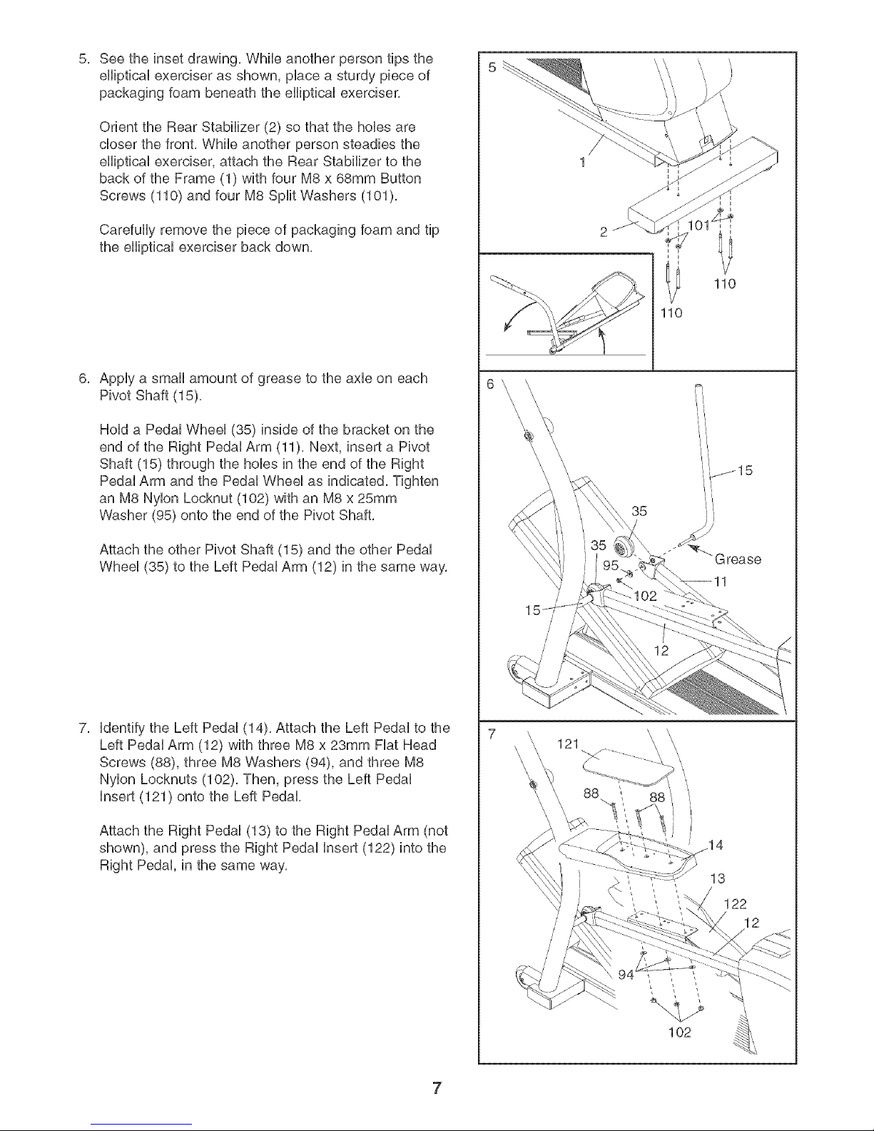
See the inset drawing, While another person tips the
eHipticaUexerciser as shown, pUacea sturdy piece of
packaging foam beneath the eHipticaUexerciser,
Orient the Rear Stabilizer (2) so that the hoUesare
closer the front, While another person steadies the
eHipticaUexerciser, attach the Rear Stabilizer to the
back of the Frame (1) with four M8 x 68mm Button
Screws (110) and four M8 Split Washers (101 ),
Carefully remove the piece of packaging foam and tip
the eHipticaUexerciser back down,
AppUya small amount of grease to the axUeon each
Pivot Shaft (15),
HoUda PedaUWheeU (35) inside of the bracket on the
end of the Right PedaUArm (11), Next, insert a Pivot
Shaft (15) through the holes in the end of the Right
Pedal Arm and the Pedal Wheel as indicated, Tighten
an M8 Nylon Locknut (102) with an M8 x 25mm
Washer (95) onto the end of the Pivot Shaft,
110
110
Attach the other Pivot Shaft (15) and the other Pedal
Wheel (35) to the Left Pedal Arm (12) in the same way,
Identify the Left Pedal (14), Attach the Left Pedal to the
Left Pedal Arm (12) with three M8 x 23mm Flat Head
Screws (88), three M8 Washers (94), and three M8
Nylon Locknuts (102), Then, press the Left Pedal
Insert (121) onto the Left Pedal,
Attach the Right Pedal (13) to the Right Pedal Arm (not
shown), and press the Right Pedal Insert (122) into the
Right Pedal, in the same way,
121
88
/
/
/
/
/
88
12
102
7
Page 8
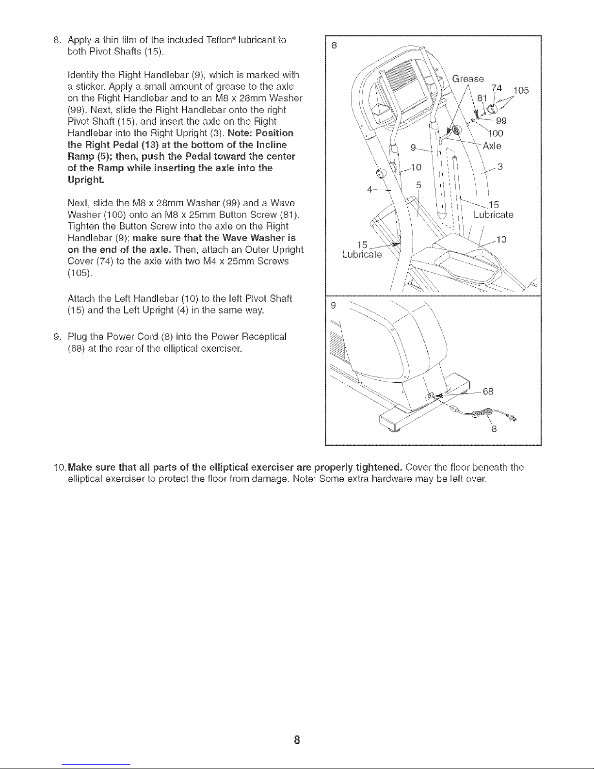
AppUya thin film of the included Teflon _Uubricantto
both Pivot Shafts (15),
Udentifythe Right HandUebar (9), which is marked with
a sticker, AppUya small amount of grease to the axUe
on the Right HandUebar and to an M8 x 28mm Washer
(99), Next, slide the Right HandUebar onto the right
Pivot Shaft (15), and insert the axUeon the Right
HandUebar into the Right Upright (3), Note: Position
the Right Pedal (13) at the bottom of the incline
Ramp (5}; then, push the Pedal toward the center
of the Ramp while inserting the a×le into the
Upright.
Next, slide the M8 x 28mm Washer (99) and a Wave
Washer (100) onto an M8 x 25mm Button Screw (81),
Tighten the Button Screw into the axUeon the Right
HandUebar (9); make sure that the Wave Washer is
on the end of the axte. Then, attach an Outer Upright
Cover (74) to the axle with two M4 x 25mm Screws
(108),
Attach the Left Handlebar (10) to the left Pivot Shaft
(15) and the Left Upright (4) in the same way,
Plug the Power Cord (8) into the Power Receptical
(68) at the rear of the elliptical exerciser,
Lubricate
9
15
_rease
74 105
/
/
/
/
!
10, Make sure that aH parts of the elliptical exerciser are properly tightened. Cover the floor beneath the
elliptical exerciser to protect the floor from damage, Note: Some extra hardware may be left over,
8
Page 9

HOW TO USE THE ELUPTmCAL EXERCmSER
HOW TO PLUG IN THE POWER CORD
This product
must be
grounded.
if it shouUd
maffunction
or break
down,
grounding
provides a
path of bast
resistance for
electric
current to reduce the risk of electric shock. This prod-
uct is equipped with a cord having an equipment-
grounding conductor and a grounding plug. PIug the
power cord into an appropriate outlet that is prop-
edy insta[Ied and grounded in accordance with all
[oca[ codes and ordinances. This product is for
use on a nomina[ 120-voJt circuit. Important: The
eHiptica[ exerciser is not compatible with GFCl-
equipped outlets.
Grounded Outlet
_rounded Outlet Box
Grounding Hug
Grounding Pin
DANG ER: mmproperconnectionof
the equipment-grounding conductor can result
in an increased risk of electric shock. Check
with a qualified electrician or serviceman if
you are in doubt as to whether the product is
properly grounded. Do not modify the pJug
provided with the product--if it win not fit the
outlet, have a proper outlet installed by a quah
ified electrician.
The green-colored rigid ear, lug, or the like extending
from the adapter must be connected to a permanent
ground such as a properly grounded outlet box cover.
Whenever the adapter is used, it must be held in
place by a metal screw, Some 2-poIe receptacJe out-
tet box covers are not grounded. Contact a quail-
fled eJectdcian to determine if the out[et box cover
is grounded before using an adapter.
Note: When the power cord is pJugged in, the ellip-
tical exerciser's incline system may automatically
ca{ibrate itseff. During the calibration process,
three dashes (- - -) wiIt appear in the consoJe dis-
play, and the ramp wili rise to the highest position
and then sink to the towest position. The calibra-
tion process wi!l tast for one to two minutes. If the
incline system does not ca!ibrate itseff, see NOW
TO CALIBRATE THE INCLINE SYSTEM on page
21.
EXERCISING ON THE ELLIPTICAL EXERCISER
To mount the elliptical exerciser, hold the handlebars
and step onto the pedal that is in the lowest position.
Next, step onto the other pedal. Push the pedals until
they begin to move with a continuous motion.
Handlebar
A temporary
adapter may _rounded Outlet Box
be used to
connect the Adapter
power cord
to a 2-pole
receptacle
as shown at
the right if a Lug
properly Metal Screw
grounded
outlet is not
available. The temporary adapter should be used only
until a properly grounded outlet can be installed by a
qualified electrician.
Pedals
To dismount the elliptical exerciser, wait until the ped-
als come to a complete stop, The eHiptica[ exerciser
does not have a free wheel; the pedals wi[[ contin-
ue to move until the flywheel stops. When the ped-
als are stationary, step off the highest pedal first,
Then, step off the lowest pedal,
9
Page 10

CONSOLE DIAGRAM
Matrix
u u u __ u u _ra_n_n_
@ @ Performance
m l
l U Endurance
@@@
Time Carbs,
O
l Aerobic
Fat Burn
Warm Up [_
Cool Down E}
/_1 _1 -I I -I_-I
/ IZI°IZ / I L .3
Note: If there is a sheet of clear plastic on the face
of the console, remove it before using the console.
Zones
6
5
A ½!ARNING
Odometer l!
Auto Br:,eze
7b reduce risk of serious injury r_ ad and und_'rstand tile
user's manual, allinstn_ctions, and tile lt,amingt, be/iJt_ use
Ke(7: childtl,n awa!v
F_n
FEATURES OF THE CONSOLE
The advanced console offers a selection of features
designed to make your workouts more enjoyable and
effective. When the manual mode of the console is
selected, the resistance of the elliptical exerciser and
the angle of the ramp can be changed with the touch
of a button. As you exercise, the console will provide
continuous exercise feedback. You can even measure
your heart rate using the handgrip pulse sensor.
The console also offers fifteen preset programs. Each
program automatically changes the resistance of the
elliptical exerciser and prompts you to increase or
decrease your pace as it guides you through an effec-
tive workout.
in addition, the console features four heart rate pro-
grams that automatically change the resistance of the
elliptical exerciser and prompt you to vary your pace to
keep your heart rate near a target level as you exer-
cise.
The console also features iFiT.com interactive technol-
ogy. Having iFIT.com technology is like having a per-
I
j iX
Heart Rate
v i
_V - - Z- _-7 _Z- ZZZZZ
sonal trainer in your home. Using a stereo audio cable,
you can connect the elliptical exerciser to your portable
stereo, home stereo, computer, or VCR and play spe-
cial iFIZcom MPS, CD, and video programs (iFIT.com
MP8 programs, CDs, and videoeassettes are available
separately), iFIT.com programs automatically control
the resistance of the elliptical exerciser and prompt
you to vary your pace as a personal trainer coaches
you through every step of your workout. High-energy
music provides added motivation. To purchase and
download iFiT.com MP3 programs, go to
www.iFiT.com. To purchase iFiT.com CDs and
videocassettes, call toll-free 1-888-825-2588.
With the elliptical exerciser connected to your comput-
er, you can also go to our Web site at www.iFIT.com
and access programs directly from the internet.
Explore wwwJFlT.com for more information.
To use the manual mode of the console, follow the
steps beginning on page 11. To use a preset
program, see page 13. To use a heart rate program,
see page 14. To use an iFIT.com MP3, CD, or video
program, see page 19. To use an iFIT.com program
directly from our Web site, see page 20.
10
Page 11

Press any button on the consob or begin
pedaling to turn on the console.
Make sure that the power cord is properly
plugged in (see page 9), Next, press any button
on the console or begin pedaling to turn on the
console, After a few seconds, the console dis-
plays will light, A tone will then sound and the
console will be ready for use,
Select the manua[ mode.
When the power is
turned on, the manu-
al mode will be
selected, if you have
sebcted a program
O @
U U
m O
[] U
U B
•[][]mUU
or the iFIT,com
mode, reselect the
manual mode by pressing the Programs button
repeatedly until a track appears in the matrix,
Make sure that the letters "iFIT" do not appear in
the center of the display,
Begin pedaling and change the resistance of
the elliptica[ exerciser as desired.
As you pedal,
change the resis= R,,_,sta,,_._,
tance of the elliptical
exerciser by press-
ing the 1 Step Resis-
tance buttons. Note:
After the 1 Step
Resistance buttons are pressed, it will take a
moment for the elliptical exerciser to reach the
selected resistance level.
Adjust the angb of the ramp as desired.
As you pedal,
change the angle of
the ramp by pressing
the 1 Step Ramp
buttons. Note: After
the 1 Step Ramp
buttons are pressed,
it will take a moment for the ramp to reach the
selected angle.
Monitor your progress with the matrix, the
Training Zones bar, and the displays.
The matrix--When the manual mode or the
iFiT.com mode is selected, the matrix wiii show a
track representing 1/4
mile. As you exercise,
the indicators around
the track will light in
succession until the
I U
O
[]
@OU
m
entire track is lit. The
track wiii then darken
and the indicators wiii again begin to light in suc-
cession.
The Training Zones
bar--The Training
Zones bar wiii show
the approximate inten-
sity level of your exer-
cise, if four indicators
in the bar are lit, for
example, the bar
shows that your pace
Training Zones
Pe_ormance
Endurance
4eteblc
Fat Burn
Warm Up
Cool Down
D
is ideal for fat burning,
The Odometer dis-
play--The Odometer
Odometer
display wili show the
distance that you
have pedaled during
,:-'.5'
Distance
your workout,
To see the total distance pedaled since the ellipti-
cal exerciser was purchased, press the Odometer
button; the words "Total Miles" and the total num-
ber of miles wiii appear in the display.
To see the total distance pedaled during a recent
time period, such as the most recent month,
press the Odometer button again; the words "My
Miles" and the total number of miles will appear in
the display. To reset this number, hold down the
Odometer button for a few seconds.
To again see the distance that you have pedaled
during your workout, press the Odometer button
again.
The center display--
The center display wiil
_me
show the elapsed
time, the resistance
/cl:c_I _I Id
level of the elliptical
exerciser, your pedal-
ing speed, your pedal-
ing pace, in revolutions per minute (RPM), and
the angle of the ramp, The display wiil change
from one number to the next every few seconds,
Note: When a program is selected, the display wiil
show the time remaining in the program instead
of the elapsed time,
11
Page 12

The right display--
The right display wHU
show the approxio
mate number of
grams of carbs you
have burned and the
approximate number of cabrbs you have burned,
The dispUay wHUchange from one number to the
next every few seconds, The dispUay wHUabo
show your heart rate when you use the handgrip
puUsesensor,
Measure your heart rate if desired.
If there are
thin sheets of
plastic on the
metal con-
tacts on the
handgdp
pulse sensor,
pee[ off the
plastic. To
measure your
heart rate,
hold the contacts; your palms must be resting
against the contacts. Avoid moving your hands
or gripping the contacts too tightly.
When your pulse is
detected, one or two
dashes (--) wiil
appear in the right
display, and then
your heart rate wiil be
shown, For the most
accurate heart rate reading, hold the contacts for
at bast 15 seconds,
/2-'
_Rafe
Calorles
!
'5'/5'
I
if your heart rate is not shown, make sure that
your hands are positioned as described, Be care°
ful not to move your hands excessively or to
squeeze the metal contacts too tightly. For optio
mal performance, clean the metal contacts using
a soft cloth; never use alcohol, abrasives, or
chemicals,
Turn on the fan if desired.
To turn on the fan at
low speed, press the
Auto Breeze Fan but° Fan
ton; the number 1 wiil
appear next to the
word "Fan" in the dis°
play, To turn on the
fan at medium speed, press the button a second
time; the number 2 wiil appear, To turn on the fan
at high speed, press the button a third time; the
number 3 wiil appear, To select the Auto mode,
press the button again; the word "Auto" wiil
appear, When the auto mode is selected, the
speed of the fan wiil automatically increase and
decrease as you increase and decrease your
pedaling speed,
To turn off the fan, press the Auto Breeze Fan
button again, Note: if the pedals are not turned
for a few minutes, the fan will automatically turn
off,
When you are finished exercising, the console
wi[[ automatically turn off.
if the pedals are not moved for several seconds, a
tone wiil sound, the console wiil pause, and the
time wiil begin to flash in the center display,
Note: if you continue to hold the pulse sensor, the
right display will show your heart rate for up to 30
seconds, The display will then show your heart
rate along with the other modes,
if the pedals are not moved for about five mino
utes, the console wili turn off and the displays wili
be reset,
12
Page 13

HOW TO USE A PRESET PROGRAM
Press any button on the console or begin
pedaling to turn on the console.
See step 1 on page 11,
Select one of the fifteen preset programs.
To sebct one of the
fifteen preset pro-
grams, press the
Programs button w..ig_,_Lo_ o
repeatedUy until the
words "Weight Loss,"
"Aerobic," or
"Performance" and the number 1,2, 3, 4, or 5
appear in the center of the dispUay,
pace, When the words "Too Fast" appear,
decrease your pace, When the words "On Pace"
appear, your pace matches the pace setting for
the current segment,
(_) On Paz, e
Too S_'
Important: The pace settings are intended
only to provide motivation. Your actual pace
may be sJower than the pace settings. Make
sure to exercise at a pace that is comfortable
for you.
When a preset program is sebcted, a profile of
the resistance settings of the program wHUscroll
across the matrix, The center dispUay wHUshow
how bng the program wHUUast,
Press the Start button or begin pedaling to
start the program.
Each program is divided into several one-minute
segments, One resistance setting and one pace
setting are programmed for each segment, Note:
The same resistance setting and/or pace setting
may be programmed for two or more consecutive
segments,
The resistance set-
ting for the first Current Segment
segment will be
shown in the flash-
ing Current
Segment column
of the matrix, (The
pace settings are not shown in the matrix,) The
resistance settings for the next several segments
will be shown in the columns to the right,
As you exercise, the Target Pace guide wiii help
you to keep your pedaling pace near the pace
setting for the current segment, When the words
"Too Slow" appear in the display, increase your
When only three seconds remain in the first seg-
ment of the program, both the Current Segment
column and the column to the right will flash, a
series of tones will sound, and all resistance set-
tings will move one column to the left. The resis-
tance setting for the second segment will then be
shown in the flashing Current Segment column,
and the resistance of the elliptical exerciser will
change to the resistance setting for the second
segment, Note: if all of the indicators in the
Current Segment column are lit after the resis-
tance settings have moved to the left, the resis-
tance settings may move downward so only the
highest indicators appear in the matrix,
The program wiii continue until the resistance
setting for the last segment is shown in the
Current Segment column and the last segment
ends,
Note: During the program, you can override the
resistance setting for the current segment, if
desired, by pressing the 1 Step Resistance but-
tons, However, when the next segment begins,
the resistance will change if a different resistance
setting is programmed for the next segment,
if you stop pedaling for several seconds, a tone
will sound and the program will pause, To restart
the program, simply resume pedaling,
13
Page 14

Adjust the angJe of the ramp as desired.
See step 4 on page 11,
Monitor your progress with the displays.
See step 5 on page 11,
Measure your heart rate if desired.
See step 6 on page 12,
HOW TO USE A HEART RATE PROGRAM
Each heart rate program heUpsyou to keep your heart
rate near a target heart rate setting during your work-
out,
Follow the steps below to use a heart rate program,
Press any button on the consoJe or begin
peda[ing to turn on the console.
Turn on the fan if desired.
See step 7 on page 12.
When the program is finished, the console
will automatically turn off.
See step 8 on page 12,
See step 1 on page 11,
Select one of the four heart rate programs.
To seUect a heart rate
program, press the
repeatedly until the
words "Heart Rate"
and the number 1,2,
3, or 4 appear in the
center of the display,
As each heart rate program is seUected, a profile
of the target heart rate settings of the seUected
program wH[scroll across the matrix. The center
dispUaywH[show how [ong the program wH[ [ast.
Enter a maximum target heart rate setting.
When a heart rate
program is selected,
the heart symbol and
the word "RATE" will
appear in the right
display and the maxi-
mum target heart rate
setting will flash, If desired, press the Heart Rate
buttons to change the maximum target heart rate
setting,
@ Rate
l Ft Ft
l I_l t_t
Hold the handgrip pulse sensor.
To use a heart rate program, you must use the
handgr[p pulse sensor (see step 6 on page 12), It
is not necessary to hold the handgrips continu-
ously during the program, However, you should
hold the handgrips frequently for the program to
operate properly, Each time you hold the hand-
grips, keep your hands on the meta[ contacts
for at least 30 seconds.
14
Page 15

Press the Start button to start the program.
Each heart rate program is divided into one-
minute segments. One target heart rate setting is
programmed for each segment. Note: The same
target heart rate setting may be programmed for
two or more consecutive segments.
The target heart
rate setting for the Current Segment
first segment wHU
be shown in the
flashing Current
Segment coUumn
_uaJmB_m
8ouu_JuoJu
m6Dg_l
um
of the matrix. The
target heart rate settings for the next seven seg-
ments wHUbe shown in the coUumns to the right.
When onUythree seconds remain in the first seg-
ment of the program, both the Current Segment
coUumnand the coUumn to the right wHUflash, a
series of tones wHUsound, and all target heart
rate settings wifl move one column to the left. The
target heart rate setting for the second segment
wHUthen be shown in the flashing Current
important: The target heart rate settings are
intended only to provide motivation. Your
actual heart rate may be sJower than the tar-
get heart rate settings. Make sure to exercise
at a pace that is comfortable for you.
The program will continue until the target heart
rate setting for the last segment is shown in the
Current Segment column of the matrix and the
last segment ends.
Note: During the program, you can manually over-
ride the resistance setting for the current seg-
ment, if desired, with the 1 Step Resistance but-
tons. However, when the console compares your
heart rate to the target heart rate setting, the
resistance of the elliptical exerciser may automat-
ically increase or decrease to bring your heart
rate closer to the target heart rate setting.
if you stop pedaling for several seconds, a tone
will sound and the program will pause. To restart
the program, simply resume pedaling.
Adjust the angle of the ramp as desired.
As you pedal the consob wHUreguUarUycompare
your heart rate to the target heart rate setting. If
your heart rate is too far below or above the tar-
get heart rate setting, the resistance of the ellipti-
cal exerciser will automatically increase or
decrease to bring your heart rate closer to the
target heart rate setting.
The Target Pace guide will prompt you to
increase or decrease your pedaling pace during
the program. When the words "Too Slow" appear
in the display, increase your pace. When the
words "Too Fast" appear, decrease your pace.
When the words "On Pace" appear, maintain your
current pace.
Target Pace Target Pace
On Pace
See step 4 on page 11.
Monitor your progress with the displays.
See step 5 on page 11.
Turn on the fan if desired.
See step 7 on page 12.
When the program is finished, the consote
wilt automatically turn off.
See step 8 on page 12.
15
Page 16

HOW TO CONNECT THE ELUPTICAL
EXERCISER TO USE IFIT.COM PROGRAMS
To use iFIT.com MP3 or CD programs, the eHipticaU
exerciser must be connected to your MP3 pUayer,CD
player, portaMe stereo, home stereo, or computer, See
pages 16 and 17 for connecting instructions, To use
iFIT.com programs directly from our Web site, the
eHipticaUexerciser must be connected to your comput-
er, See page 17 for connecting instructions, To use
iFIT.com video programs, the eHipticaUexerciser must
be connected to your VCR, See page 18 for connect-
ing instructions,
HOW TO CONNECT YOUR MP3 PLAYER OR CD
PLAYER
A, Hug one end of the included 1/8" to 1/8" stereo
audio came into the input jack on the consoUe, Hug
the other end of the came into a jack on your MP3
pUayeror CD player, Hug your headphones into the
headphone jack on the console,
HOW TO CONNECT YOUR PORTABLE STEREO
Note: If your stereo has an RCA=type AUDIO OUT
jack, see instruction A beJow. If your stereo has a
1t8" LINE OUT jack, see instruction B. If your
stereo has only a PHONES jack, see instruction C.
A, Plug one end of a long 1/8" to RCA stereo audio
cable (available at electronics stores) into the input
jack on the console, Plug the other end of the cable
into the AUDIO OUT jack on your stereo,
A/B
'.@_ (-o-).
',IIL
AUDIOOUT LIN_OUT
," R_O,T_ ,: ,;_ ;
i LE_T I = =l= =
L ...... I
l
Audio Cable
....Headphones
r................. , ,-................. ,
i LINEOUT_ ! i PHONES(_!
L ; L I ',
Audio
Cable
B,
See the drawing above, Plug one end of a long 1/8"
to 1/8" stereo audio cable (available at electronics
stores) into the input jack on the console, Plug the
other end of the cable into the LINE OUT jack on
I
your stereo, Note: While the cable is plugged into
the LINE OUT jack, do not plug your headphones
into the headphone jack on the console,
C,
Plug one end of a long 1/8" to 1/8" stereo audio
cable (available at electronics stores) into the input
jack on the console, Plug the other end of the cable
into the PHONES jack on your stereo, Plug your
headphones into the headphone jack on the con-
sole,
,@ @ ,,_
,......._ , '_i _
L-I===_=
i _ '/i
i
i
i
i
' ........ 6
PNONES©=:
............... J__:
Cable
Audi°I
;t
....Headphones
16
Page 17

HOW TO CONNECT YOUR HOME STEREO HOW TO CONNECT YOUR COMPUTER
Note: if your stereo has an unused LiNE OUT jack,
see instruction A below. [f the LmNEOUT jack is
being used, see instruction B.
A. Hug one end of a long 1/8" to RCA stereo audio
cable (available at electronics stores) into the input
jack on the console. Hug the other end of the cable
into the LiNE OUT jack on your stereo. Note: While
the cable is plugged into the LiNE OUT jack, do not
plug your headphones into the headphone jack on
the console.
A
r ......
'.@_@.
L .... L= I
LINEOUT _
.............. 1....
A. Hug one end of a long 1/8" to 1/8" stereo audio
cable (available at electronics stores) into the input
jack on the console. Hug the other end of the cable
into the LiNE OUT jack on your computer. Note:
While the cable is plugged into the LiNE OUT jack,
do not plug your headphones into the headphone
jack on the console.
a
11
) ........i...... ,
i
= ooc
=1
Audio Cable
B. Plug one end of a long 1/8" to RCA stereo audio
cable (available at electronics stores) into the input
jack on the console. Hug the other end of the cable
into an RCA Y-adapter (available at electronics
stores). Next, remove the wire that is currently
plugged into the LiNE OUT jack on your stereo and
plug the wire into the unused side of the Y-adapter.
Hug the Y-adapter into the LiNE OUT jack on your
stereo. Note: While the Y-adapter is plugged into
the LiNE OUT jack, do not plug your headphones
into the headphone jack on the console.
B
,@" @u
i® .... ?--_
RCA
Audio Y-adapter
Cable
Wire removed from----_-_
LINE OUT jack
17
Page 18

HOW TO CONNECT YOUR VCR
Note: if your VCR has an unused AUDIO OUT jack,
see instruction A below, if the AUDIO OUT jack is
being used, see instruction B. mfyou have a TV
with a bultAn VCR, see instruction B. ff your VCR
is connected to your home stereo, see NOW TO
CONNECT YOUR HOME STEREO on page 17.
A, Plug one end of a long 1/8" to RCA stereo audio
cable (avalable at electronics stores) into the input
jack on the console, Plug the other end of the cable
into the AUDIO OUT jack on your VCR,
A
r ...... i
L_Ot. ;
Audio Cable
B, Plug one end of a long 1/8" to RCA stereo audio
cable (avalable at electronics stores) into the input
jack on the console, Plug the other end of the cable
into an RCA Y-adapter (avalable at electronics
stores), Next, remove the wire that is currently
plugged into the AUDIO OUT jack on your VCR
and plug the wire into the unused side of the Y-
adapter, Plug the Y-adapter into the AUDIO OUT
jack on your VCR,
Audio Cable Y-adapter
.__,_a_h 4 _--_
Wire removed from ----_:z_
AUDIO OUT jack
18
Page 19

HOW TO USE AN mFmT.COMMP3, CD, OR
VIDEO PROGRAM
To use an iFIT.com MP3, CD, or video program, the
elliptical exerciser must be connected to your MP3
player, CD player, or VCR. See HOW TO CONNECT
THE ELLiPTiCAL EXERCISER TO USE IFIT.COM
PROGRAMS on pages 16 to 18. To purchase and
download iFIT.com MP3 programs, go to
wwwJFIT.com. To purchase iFIT.com CDs or video-
cassettes, call toll-free 1-888-825-2588.
Follow the steps below to use an iFIT.com MP3, CD,
or video program.
Follow the steps below to use an iFIT.com CD or
video program.
Press any button on the console or begin
pedaling to turn on the console.
The program wiii function in almost the same way
as a preset program (see step 3 on page 13).
However, an electronic "chirping" sound will alert
you when the resistance setting and/or pace set-
ting is about to change.
Note: If the resistance of the elliptical exerciser
and/or the pace setting does not change when
a "chirp" is heard:
Make sure that the letters "iFIT" appear in
the center of the display.
Adjust the volume of your MP3 player, CD
player, or VCR. If the volume is too high or
too low, the console may not detect the pro-
gram signals.
Make sure that the audio cable is properly
connected and that it is fully plugged in.
Adjust the angle of the ramp as desired.
See step 1 on page 11.
Select the iFIT.com mode.
To select the
iFIT.com mode, press
the Programs button
repeatedly until the
track and the letters
"iFIT" light in the cen-
JumuJm
m R
m m
J u
J u
u J
Rmmmnm
i FIT
ter of the display.
Press the Play button on your MP3 player, CD
player, or VCR.
Note: if you are using an iFIT.com CD, insert the
CD into your CD player; if you are using an
iFIT.com videocassette, insert the videocassette
into your VCR.
A moment after the play button is pressed, your
personal trainer wiii begin guiding you through
your workout. Simply follow your personal trainer's
instructions.
See step 4 on page 11.
Monitor your progress with the displays.
See step 5 on page 11.
Measure your heart rate as desired.
See step 6 on page 12.
Turn on the fan if desired.
See step 7 on page 12.
When the program is finished, the console
wilt automatically turn off.
See step 8 on page 12.
19
Page 20

HOW TO USE PROGRAMS DIRECTLY FROM
OUR WEB SITE
Our Web site at www, iFIT,com allows you to play
iF[T,com programs directly from the internet, To use
programs from our Web site, the elliptical exerciser
must be connected to your home computer, See HOW
TO CONNECT YOUR COMPUTER on page 17, in
addition, you must have an internet connection and an
internet service provider, A list of specific system
requirements is found on our Web site,
Follow the steps below to use a program from our
Web site,
Follow the on-line instructions to start the
program.
When you start the program, an on-screen count-
down wiil begin,
Return to the e[Hptica[ exerciser and begin
pedaling.
When the on-screen countdown ends, the pro-
gram will begin, The program will function in
almost the same way as a preset program (see
step 3 on page 13), However, an electronic "chirp-
ing" sound will alert you when the resistance set-
ting and/or pace setting is about to change,
Press any button on the console or begin
pedaling to turn on the console.
See step 1 on page 11,
Select the iFIT.com mode.
To select the
iFIT,com mode, press
the Programs button
repeatedly until the
track and the letters
"iFIT" light in the cen-
mO_OBU
m B
I m
m
U U
m B
immmmm
iFIT
ter of the display,
Go to your computer and start an internet
connection.
Start your Web browser, if necessary, and go
to our Web site at wwwJFIT.com.
Follow the desired [inks on our Web site to
select a program.
Adjust the angle of the ramp if desired.
See step 4 on page 11,
Monitor your progress with the displays.
See step 5 on page 11,
Measure your heart rate if desired.
See step 6 on page 12,
Turn on the fan if desired.
See step 7 on page 12,
When the program is finished, the console
automatically turn off.
See step 8 on page 12,
Read and follow the on-line instructions for using
a program,
2O
Page 21

MAINTENANCE AND TROUBLESHOOTmNG
inspect and properUytighten aHparts of the eHipticaU
exerciser reguUarUy.RepUace any worn parts immedi-
ateUy.
For smooth
operation of the
elliptical exer-
ciser, inspect
and clean the
incline ramp
regularly using
a soft cloth and
mild detergent.
Other parts of
the elliptical
exerciser can
also be cleaned
in this way. Keep tiquid$ off the console. Never use
abrasives or solvents.
PULSESENSOR TROUBLESHOOTING
if the handgrip pulse sensor does not function proper-
ly, see step 6 on page 12,
Incline
Ramp
HOW TO MOVE THE ELLIPTICAL EXERCISER
Stand in front of the elliptical exerciser, hold the frame
firmly, and place one foot against the ramp in the
location shown below, Pull the frame until the elliptical
exerciser can be moved on the front wheels, and
carefully move the elliptical exerciser to the desired
location, Then, place one foot against the ramp, and
lower the elliptical exerciser. Due to the size and
weight of the elliptical exerciser, use extreme cau-
tion while moving and towering it.
Frame
/
Place your
here
HOW TO CALIBRATE THE INCLINE SYSTEM
if the elliptical exerciser's incline system is not working
properly, activate the calibration process by following
the steps below,
Hold down the Start button and the Heart Rate
increase button at the same time for about five
seconds. Note: Numbers may appear in the dis-
play; disregard these numbers.
2. Press the Start button again. Note: A combination
of letters and numbers will appear in the display.
3. Press the 30° 1 Step Ramp button. The ramp will
rise to the highest position and then sink to the
lowest position.
4. Press the Start button three times, The console
will then be in the normal operating mode and the
elliptical exerciser will be ready for use.
Wheel
HOW TO LEVEL THE ELLIPTICAL EXERCISER
if the elliptical
exerciser rocks
during use, turn
one or both of
the leveling feet
under the rear
stabilizer until
the rocking
motion is elimi-
nated,
Leveling
21
Page 22

CONDmTmONmNGGUmDEUNES
kWARNING-.
Before beginning this or any exercise pro-
gram, consult your physician. This is espe-
cially important for persons over the age of 35
or persons with pre-existing health problems.
During the first few minutes of exercise, your body
uses easily accessible carbohydt:ate calories for ener-
gy, Only after the first few minutes of exercise does
your body begin to use stored fat calories for energy,
if your goal is to burn fat, adjust the intensity of your
exercise until your heart rate is near the lowest num-
ber in your training zone as you exercise,
The pulse sensor is not a medical device.
Various factors, including the user's move-
ment, may affect the accuracy of heart rate
readings. The pulse sensor is intended onty
as an exercise aid in determining heart rate
trends in general
The following guidelines wiii help you to plan your
exercise program, Remember that proper nutrition
and adequate rest are essential for successful results,
EXERCISE iNTENSiTY
Whether your goal is to burn fat or to strengthen your
cardiovascular system, the key to achieving the
desired results is to exercise with the proper
The proper intensity level can be found by using your
heart rate as a guide, The chart below shows recom-
mended heart rates for fat burning, maximum fat
burning, and cardiovascular (aerobic) exercise,
165 155 145 140 130 125 115 _
For maximum fat burning, adjust the intensity of your
exercise until your heart rate is near the middle num-
ber in your training zone as you exercise,
Aerobic Exercise
if your goal is to strengthen your cardiovascular sys-
tem, your exercise must be "aerobic," Aerobic exer-
cise is activity that requires large amounts of oxygen
for prolonged periods of time, This increases the
demand on the heart to pump blood to the muscles,
and on the lungs to oxygenate the blood, For aerobic
exercise, adjust the intensity of your exercise until
your heart rate is near the highest number in your
training zone as you exercise,
WORKOUT GUIDELINES
Each workout should include the following three parts:
A warm-up, consisting of 5 to 10 minutes of stretching
and light exercise, A proper warm-up increases your
body temperature, heart rate, and cimulation in prepa-
ration for exercise,
145 138 130 125 118 110 103 _
125 120 !!5 110 105 95 90
20 30 40 50 60 70 80
To find the proper heart rate for you, first find your age
near the bottom of the chart (ages are rounded off to
the nearest ten years), Next, find the three numbers
above your age, The three numbers are your "training
zone," The lower two numbers are recommended
heart rates for fat burning; the highest number is the
recommended heart rate for aerobic exercise,
Fat Burning
To burn fat effectively, you must exercise at a relative-
ly low intensity level for a sustained period of time,
Training zone exercise, consisting of 20 to 30 min-
utes of exercising with your heart rate in your training
zone, (During the first few weeks of your exercise
program, do not keep your heart rate in your training
zone for longer than 20 minutes,)
A coo!-down, with 5 to 10 minutes of stretching, This
will increase the flexibility of your muscles and will
help to prevent post-exercise problems,
EXERCISE FREQUENCY
To maintain or improve your condition, complete three
workouts each week, with at bast one day of rest
between workouts, After a few months of regular exer-
cise, you may complete up to five workouts each week
if desired, The key to success is to make exercise a
regular and enjoyable part of your everyday life,
22
Page 23

SUGGESTED STRETCHES
The correct form for several basic stretches is shown at the right,
Move slowly as you stretch--never bounce,
1. Toe Touch Stretch
Stand with your knees bent slightly and slowly bend forward from
your hips, Allow your back and shoulders to relax as you reach
down toward your toes as far as possible, Hold for 15 counts, then
relax, Repeat 3 times, Stretches: Hamstrings, back of knees and
back,
2. Hamstring Stretch
Sit with one leg extended, Bring the sob of the opposite foot toward
you and rest it against the inner thigh of your extended leg, Reach
toward your toes as far as possible, Hold for 15 counts, then relax,
Repeat 3 times for each leg, Stretches: Hamstrings, lower back and
groin,
3. CaJf/Achiltes Stretch
With one leg in front of the other, reach forward and place your
hands against a wall, Keep your back leg straight and your back
foot fiat on the floor, Bend your front leg, ban forward and move
your hips toward the wall, Hold for 15 counts, then relax, Repeat 3
times for each leg, To cause further stretching of the achilles ten-
dons, bend your back leg as well, Stretches: Calves, achilles ten-
dons and ankles,
1
4. Quadriceps Stretch
With one hand against a wall for balance, reach back and grasp
one foot with your other hand, Bring your heel as close to your but-
tocks as possible, Hold for 15 counts, then relax, Repeat 3 times for
each leg, Stretches: Quadriceps and hip muscles,
5. Inner Thigh Stretch
Sit with the sobs of your feet together and your knees outward, Puii
your feet toward your groin area as far as possible, Hold for 15
counts, then relax, Repeat 3 times, Stretches: Quadriceps and hip
muscles,
23
Page 24

24
Page 25

PART LiST--Model No. NELg0951 Rtt04A
Key Qty. Description Key Qty. Description Key Qty. Description
No. No. No.
1 1 Frame 45 1 Small Pulley 87 2 M8 x 16mm Washer
2 1 Rear Stabilizer 46 1 UdUerPulley 88 6 M8 x 23mm FUat
3 1 Right Upright 47 1 Resistance Motor Head Screw
4 1 Left Upright 48 1 Power Board Cover 89 1 M8 x 57mm Screw
5 1 UncHneRamp 49 1 Power Board 90 1 M6 x 38mm BoUt
6 1 ConsoUe Frame 50 1 Power Board 91 1
7 1 Lower Ramp Cap Bracket 92 36 M4 x 16mm Screw
8 1 Power Cord 51 1 UdUerPulley Bracket 93 1 M6 x 8mm Button
9 1 Right HandUebar 52 1 Reed Switch CUamp Screw
10 1 Left HandUebar 53 1 Reed Switch 94 8 M8 Washer
11 1 Right PedaUArm 54 2 PHUowBUockSet 95 2 M8 x 25mm Washer
12 1 Left PedaUArm 55 2 Bearing BUockSet 96 3 M8 x 9.5mm Screw
13 1 Right PedaU 56 4 Crank Arm Bushing 97 5 M5 x 16mm BoUt
14 1 Left PedaU 57 4 Pulley Spacer 98 2 M8 x 23mm Washer
15 2 Pivot Shaft 58 1 Crank Spacer 99 4 M8 x 28mm Washer
16 4 M4 Star Washer 59 4 Ramp Bushing 100 2 Wave W/asher
17 1 Console 60 4 Incline Motor Spacer 101 12 M8 Split Washer
18 1 Hand Grip Pulse 61 4 Pedal Wheel 102 13 M8 Nylon Locknut
Sensor Bushing 103 2 Large Snap Ring
19 1 Rear Base Plate 62 4 Pivot Bushing 104 2 Handlebar Endcap
20 1 Front Base Plate 63 2 Inner Upright Cover 105 8 M4 x 25mm Screw
21 1 Right Rear Side 64 2 Pivot Arm Cover 106 8 M4 x 16mm Round
Shield 65 1 Magnet Head Screw
22 1 Left Rear Side 66 1 Wedge 107 2 Bolt Set
Shield 67 1 Incline Reed Switch 108 4 M8 x 56mm Button
23 1 Right Front Side 68 1 Power Receptical Screw
Shield 69 1 Belt 109 1 Reed Switch Plate
24 1 Left Front Side 70 1 Grommet 110 8 M8 x 68mm Button
Shield 71 2 Hairpin Screw
25 1 Front Cover 72 2 Snap Ring 111 8 M4 x 12mm Screw
26 1 Right Foot Rail 73 1 Flywheel Spacer 112 4 M8 x 76mm Button
27 1 Left Foot Rail 74 2 Outer Upright Cover Bolt
28 1 Upper Ramp Cap 75 1 Upper Wire Harness 113 2 M8 x 20mm Button
29 4 Pivot Shaft Sleeve 76 1 Extension Wire Screw
30 4 Handle Bar Cover Harness 114 2 M6 Nut
31 4 Frame Endcap 77 1 Lower Wire Harness 115 4 M6 x lOmm Button
32 2 Frame Cushion 78 4 M4 x 14mm Screw Screw
33 4 Leveling Foot 79 4 M5 Nylon Locknut 116 5 M4 x 19mm Screw
34 2 Wheel 80 2 M8 x 45mm Button 117 2 M4 x 30mm Screw
35 2 Pedal Wheel Screw 118 1 Short Clevis Pin
36 1 Flywheel 81 4 M8 x 25mm Button 119 1 Long Clevis Pin
37 1 Pulley Screw 120 2 Foam Grip
38 1 Right Crank Arm 82 4 M5 Washer 121 1 Left Pedal Insert
39 1 Left Crank Arm 83 2 Flange Screw 122 1 Right Pedal Insert
40 1 Incline Axle 84 2 M8 x 52mm Button # 2 Hex Key
41 1 Pulley Axle Screw # 1 Grease
42 1 Lift Motor 85 2 M8 x 41mm Button # 1 Teflon _ Lubricant
43 1 "C" Magnet Screw # 1 User's Manual
44 1 Spring 86 2 Large Wave Washer
Note: # indicates a non-illustrated part. Specifications are subject to change without notice, See the back cover
of this manual for information about ordering replacement parts.
25
Page 26

EXPLODED DRAWING--Model No. NELg0951 mlo4A
112
17
80
18
100 106
99.
105 '
34 1{ / //
107 / //
31
33 108
i¢/92
k
,_,q_--4
/
27
105
63
i
16
30
¢
111,
92
29
28
120
104_,
105
99
74
105
30
62
\.
16
29 110
5
92-ff
11
78
106
1O5
107
34
/
1O7
31
33
108
26
92
26
Page 27

NEL90951 RllO4A
122
23
14
102
21
88
102
60
42
_92
_{ 116
121
118
6O
86
9 83
4O
39
35 61
102
69
95
102
88
81
84
98
56
-'" 56
117
92
82
32
\
31
92
92
33
110
110
27
Page 28

HOW TO ORDER REPLACEMENT PARTS
To order replacement parts, simply call our Customer Service Department toIFfree at 1-888-825-2588, Monday
through Friday, 6 a,m, until 6 p,m, Mountain Time (excluding holidays), To help us assist you, please be
prepared to give the following information when calling:
The MODEL NUMBER of the product (NELg0951)
The NAME of the product (NordicTrack CX 1055 elliptical exerciser)
The SERIAL NUMBER of the product (see the front cover of this manua0
,, The KEY NUMBER and DESCRiPTiON of the part(s) (see pages 25 to 27)
LiMiTED WARRANTY
WHAT iS COVERED--The entire NordicTrack '_,e!liptica! exerciser ("Product") is warranted to be free of all defects in materia! and
workmanship.
WHO iS COVERED--The original purchaser or any person receiving the Product as a gift from the original purchaser.
HOW LONG IS IT COVERED--ICON Health & Fitness, Inc. ("ICON"), warrants the product for one year after the date of purchase.
Labor is covered for one year.
WHAT WE DO TO CORRECT COVERED DEFECTS--We will ship to you, without charge, any replacement part or component, pro-
viding the repairs are authorized by ICON first and are performed by an iCON trained and authorized service provider, or, at our
option, we will replace the Product.
WHAT IS NOT COVERED--Any failures or damage caused by unauthorized sel,vice, misuse, accident, negligence, improper assem-
bly or installation, alterations, modifications without our written authorization or by failure on your part to use, operate, and maintain
as set out in your User's Manual ("ManuaF).
WHAT YOU MUST DO--Always retain proof of purchase, such as your bill of sale; store, operate, and maintain the Product as spec-
ified in the Manual; notify our Customer Set'vice Department of any defect within t0 days after discovery of the defect; as instruct-
ed, return any defected part for replacement or, if necessary, the entire product, for repair.
USER'S MANUAL--It is VERY IMPORTANT THAT YOU READ THE MANUAL before operating the Product. Remember to do the
periodic maintenance requirements specified in the Manual to assure proper operation and your continued satisfaction.
HOW TO GET PARTS AND SERVICE--Simply carl our Customer Service Department at 1-888_825-2588 and tell them your name
and address and the serial number of your Product. They will tell you how to get a part replaced, or if necessary, arrange for service
where your Product is located or advise you how to ship the Product for service. Before shipping, always obtain a Return
Authorization Number (RA No.) from our Customer Service Department; securely pack your Product (save the original shipping car-
ton if possible); put the RA No. on the outside of the carton and insure the product, include a letter explaining the product or prob-
lem and a copy of your proof of purchase if you believe the service is covered by warranty.
iCON is not responsible or liable for indirect, special or consequential damages arising out of or in connection with the use or per-
formance of the product or damages with respect to any economic loss, loss of property, loss of revenues or profits, loss of enioy-
ment or use, costs of removal, installation or other consequential damages of whatsoever nature. Some states do not allow the exclu-
sion or limitation of incidental or consequential damages. Accordingly, the above limitation may not apply to you.
The warranty extended hereunder is in lieu of any and all other warranties and any implied warranties of merchantability or fitness
for a particular purpose is limited in its scope and duration to the terms set forth herein. Some states do not allow limitations on how
long an implied warranty lasts. Accordingly, the above limitation may not apply to you.
No one is authorized to change, modify or extend the terms of this limited warranty. This warranty gives you specific legal rights and
you may have other rights which vary from state to state.
ICON HEALTH & RTNESS, INC., 1500 S. 1000 W., LOGAN, UT 84321-9813
Part No, 221452 R1104A Printed in China @2004 iCON IP, Inc,
 Loading...