

U
SER'S
M
ANUAL
CAUTION
Read all precautions and instructions in this manual before using
this equipment. Keep this manual
for future reference.
Model No. CTK62520
Model No. CTK65020
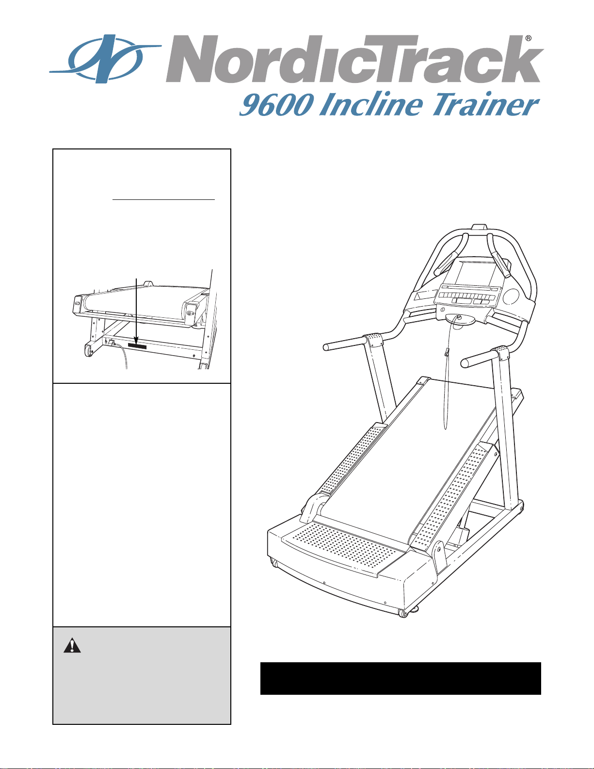
Serial No.
The serial number is found in the
location shown below. Write the
serial number in the space above.
QUESTIONS?
At FreeMotion Fitness, we’re
committed to providing complete
customer satisfaction. For assistance, call Customer Care tollfree at:
1-800-201-2109
Mon.–Fri., 8 a.m.–5 p.m. MST
Serial Number Decal

SECTION 1
Important Precautions . . . . . . . . . . . . . . . . . . . . . . . . . . . . . . . . . . . . . . . . . . . . . . . . . . . . . . . . . . . . .3
Warning Decal Placement . . . . . . . . . . . . . . . . . . . . . . . . . . . . . . . . . . . . . . . . . . . . . . . . . . . . . . . . . .5
Before You Begin . . . . . . . . . . . . . . . . . . . . . . . . . . . . . . . . . . . . . . . . . . . . . . . . . . . . . . . . . . . . . . . .6
How to Set Up the INCLINE TRAINER . . . . . . . . . . . . . . . . . . . . . . . . . . . . . . . . . . . . . . . . . . . . . . . .7
How to Move the INCLINE TRAINER . . . . . . . . . . . . . . . . . . . . . . . . . . . . . . . . . . . . . . . . . . . . . . . . .9
How to Connect the INCLINE TRAINER . . . . . . . . . . . . . . . . . . . . . . . . . . . . . . . . . . . . . . . . . . . . . .10
How to Connect your CD Player . . . . . . . . . . . . . . . . . . . . . . . . . . . . . . . . . . . . . . . . . . . . . . . . . . . .11
How to Upgrade your Console . . . . . . . . . . . . . . . . . . . . . . . . . . . . . . . . . . . . . . . . . . . . . . . . . . . . .12
SECTION 2
How to Use the Basic Console . . . . . . . . . . . . . . . . . . . . . . . . . . . . . . . . . . . . . . . . . . . . . . . . . . . . .13
How to Use the Workout TV Console . . . . . . . . . . . . . . . . . . . . . . . . . . . . . . . . . . . . . . . . . . . . . . . .26
SECTION 3
Preventive Maintenance . . . . . . . . . . . . . . . . . . . . . . . . . . . . . . . . . . . . . . . . . . . . . . . . . . . . . . . . . .29
Six-month Preventive Maintenance Record . . . . . . . . . . . . . . . . . . . . . . . . . . . . . . . . . . . . . . . . . . .31
Troubleshooting . . . . . . . . . . . . . . . . . . . . . . . . . . . . . . . . . . . . . . . . . . . . . . . . . . . . . . . . . . . . . . . .33
SECTION 4
Exercise Guidelines . . . . . . . . . . . . . . . . . . . . . . . . . . . . . . . . . . . . . . . . . . . . . . . . . . . . . . . . . . . . .35
SECTION 5
Limited Warranty . . . . . . . . . . . . . . . . . . . . . . . . . . . . . . . . . . . . . . . . . . . . . . . . . . . . . . . . . . . . . . . .39
Part List . . . . . . . . . . . . . . . . . . . . . . . . . . . . . . . . . . . . . . . . . . . . . . . . . . . . . . . . . . . . . . . . . . . . . . .41
Exploded Drawing . . . . . . . . . . . . . . . . . . . . . . . . . . . . . . . . . . . . . . . . . . . . . . . . . . . . . . . . . . . . . . .43
How to Order Replacement Parts . . . . . . . . . . . . . . . . . . . . . . . . . . . . . . . . . . . . . . . . . . . . . . . . . . .46
TABLE OF CONTENTS
1
NordicTrack is a registered trademark of ICON Health & Fitness, Inc.

2

3
1. It is the responsibility of the owner to ensure
that all users of the INCLINE TRAINER are adequately informed of all warnings and precautions.
2. Use the INCLINE TRAINER only as described
in this manual.
3. Place the INCLINE TRAINER on a level surface, with at least eight feet of clearance behind it. Do not place the INCLINE TRAINER on
any surface that blocks air openings. To protect the floor or carpet from damage, place a
mat under the INCLINE TRAINER.
4. Keep the INCLINE TRAINER indoors, away
from moisture and dust. Do not place the INCLINE TRAINER in a garage or covered patio,
or near water.
5. Do not operate the INCLINE TRAINER where
aerosol products are used or where oxygen is
being administered.
6. Do not operate the INCLINE TRAINER until it
is properly assembled (see HOW TO SET UP
THE INCLINE TRAINER on page 7).
7. Regularly inspect and tighten all parts of the
INCLINE TRAINER.
8. Keep children under the age of 12 and pets
away from the INCLINE TRAINER at all times.
9. The INCLINE TRAINER should not be used by
persons weighing more than 350 pounds.
10. Never allow more than one person on the
INCLINE TRAINER at a time.
11. Wear appropriate exercise clothes when
using the INCLINE TRAINER. Do not wear
loose clothes that could become caught in
the INCLINE TRAINER. Athletic support
clothes are recommended for both men and
women. Always wear athletic shoes. Never
use the INCLINE TRAINER with bare feet,
wearing only stockings, or in sandals.
12. When connecting the power cord (see page 10),
plug the power cord into a grounded circuit
capable of carrying 20 or more amps. No other
appliance should be on the same circuit. Do not
use an extension cord.
13. Keep the power cord away from heated surfaces.
14. Never move the walking belt while the power
is turned off. Do not operate the INCLINE
TRAINER if the power cord or plug is damaged or if the INCLINE TRAINER is not working properly. (See BEFORE YOU BEGIN on
page 6 if the INCLINE TRAINER is not working
properly.)
15. Never start the INCLINE TRAINER while you
are standing on the walking belt. Always hold
the handrails while using the INCLINE
TRAINER.
16. The INCLINE TRAINER is capable of high
speeds. Adjust the speed in small increments
to avoid sudden jumps in speed.
17. The pulse sensor is not a medical device.
Various factors, including the user's movement, may affect the accuracy of heart rate
readings. The pulse sensor is intended only
as an exercise aid in determining heart rate
trends in general.
18. Never leave the INCLINE TRAINER unattended while it is running. Always remove the
key, unplug the power cord, and switch the
on/off circuit breaker to the off position when
the INCLINE TRAINER is not in use.
19. Do not change the incline of the INCLINE
TRAINER by placing objects under it.
20. When using iFIT.com CD’s, you will be alerted
by an electronic “chirping” sound when the
speed and/or incline of the INCLINE TRAINER
is about to change. Always listen for the
“chirp” and be prepared for speed and/or incline changes. In some instances, the speed
and/or incline may change before the personal trainer describes the change.
WARNING:To reduce the risk of burns, fire, electric shock, or injury to persons, read the
following important precautions and information before operating the INCLINE TRAINER.
IMPORTANT PRECAUTIONS

4
21. When using iFIT.com CD’s, you can manually
override the speed and incline settings at any
time by pressing the SPEED and INCLINE buttons. However, when the next “chirp” is
heard, the speed and/or incline will change to
the next settings of the CD program.
22. Always remove iFIT.com CD’s from your CD
player when you are not using them.
23. Never insert or drop any object into any
opening.
24. Make sure to perform all maintenance procedures outlined in this manual. Failure to do so
will void the warranty and may result in damage to the INCLINE TRAINER.
25. DANGER:Always unplug the power
cord immediately after use, before cleaning
the INCLINE TRAINER, and before performing
the maintenance and adjustment procedures
described in this manual. Servicing other than
the procedures in this manual should be performed by an authorized service representative only.
WARNING:Before beginning this or any exercise program, consult your physician. This
is especially important for persons over the age of 35 or persons with pre-existing health problems.
Read all instructions before using. ICON assumes no responsibility for personal injury or property
damage sustained by or through the use of this product.
SAVE THESE INSTRUCTIONS
5
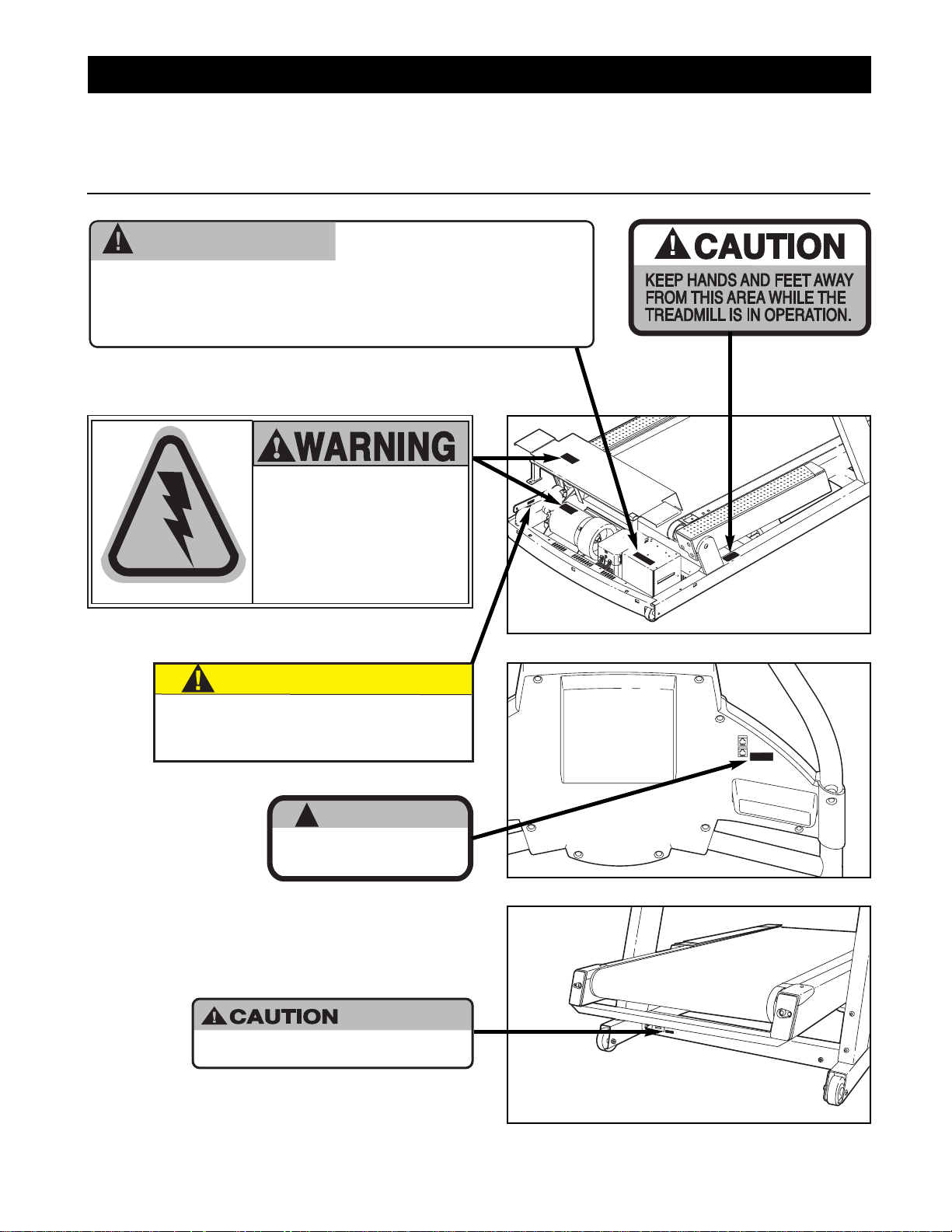
The decals shown below are found on the INCLINE TRAINER. If any decal is missing or illegible, call
Customer Care toll-free at 1-800-201-2109, Monday through Friday, 8 a.m. until 5 p.m. Mountain Time
(excluding holidays) to order a free replacement decal. Apply the decal in the location shown.
WARNING DECAL PLACEMENT
Note: This decal
is shown at 80%.
Note: There
is one decal
on each side.
Note: This decal is shown at 85%.
Note: This decal is shown at 75% of actual size.
WARNING:
HIGH VOLTAGE!
Please do not attempt to service this unit without
contacting Nordic Track Commercial Fitness Division
Customer Care at (800) 201-2109
HAZARDOUS
VOLTAGE
Disconnect power
before servicing.
CAUTION
Overtightening of J-bolt may result
in severe motor damage. Refer to the
service manual for proper tensioning
procedure, or contact Customer Care.
!
WARNING
Do not remove or insert this plug while the
safety key is inserted in the console. Touch
metal frame before removing or inserting plug.
Static sensitive components may be affected.
:
HIGH VOLTAGE
Disconnect line cord from
outlet before servicing.
6
Congratulations for selecting the revolutionary NordicTrack®9600 INCLINE TRAINER. The NordicTrack
9600 INCLINE TRAINER offers an impressive array of
features to make your workouts more effective and
enjoyable.
For your benefit, read this manual carefully before
using the 9600 INCLINE TRAINER. If you have addi-
tional questions, please call Customer Care toll-free at
1-800-201-2109, Monday through Friday, 8 a.m. until 5
p.m. Mountain Time (excluding holidays). To help us
assist you, please note the product model number and
serial number before calling. The model number of the
INCLINE TRAINER is CTK62520 or CTK65020. The
serial number can be found on a decal attached to the
INCLINE TRAINER (see the front cover of this manual
for the location of the decal).
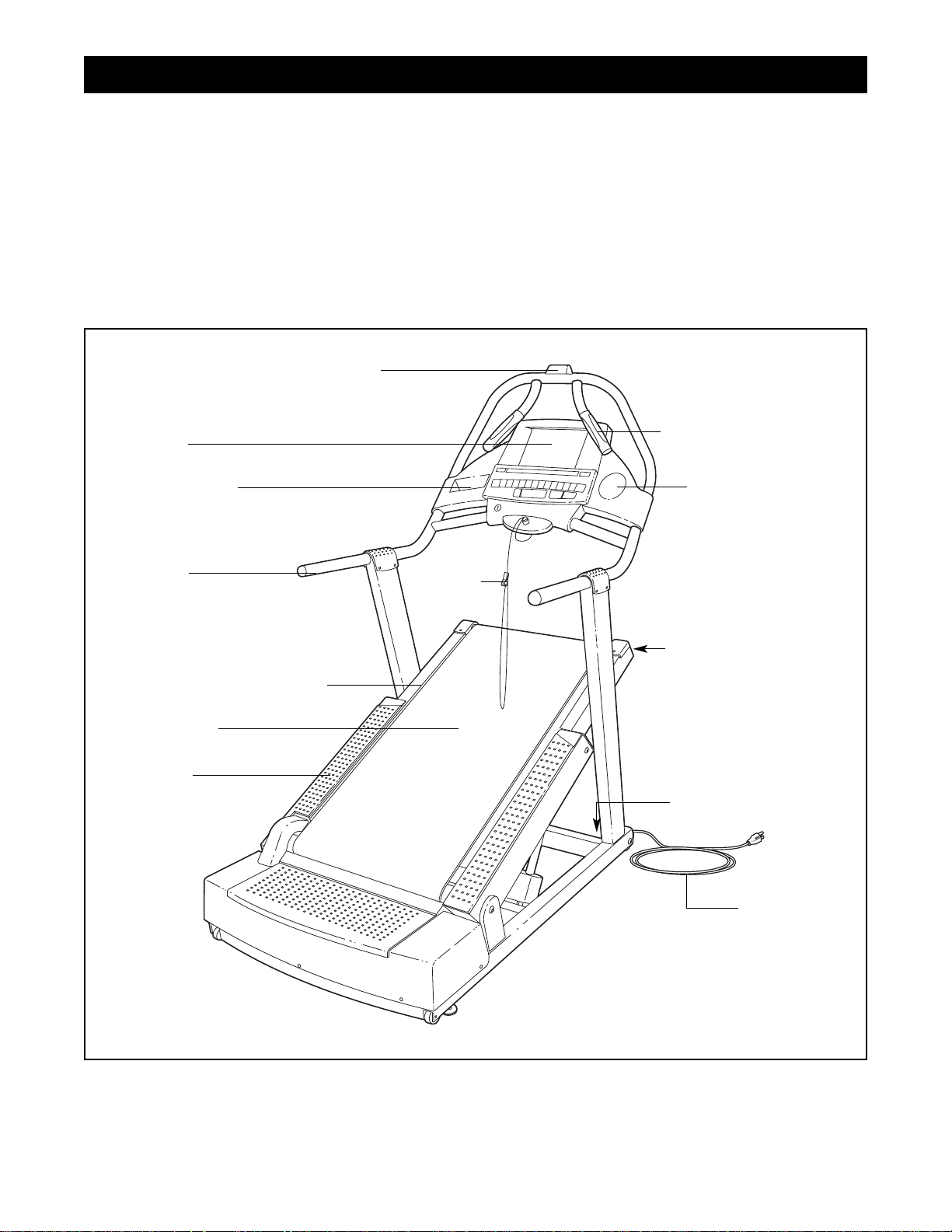
Before reading further, please familiarize yourself with
the parts that are labeled in the drawing below.
Handrail
Accessory Tray
Console
Polar®Chest Pulse Sensor Receiver
Key/Clip
On/off Circuit Breaker
Walking Belt
Cushioned Walking Platform
Foot Rail
Power Cord
Roller Adjustment Bolt
Water Bottle Holder
Handgrip Pulse Sensor
BEFORE YOU BEGIN
7
Assembly requires two persons. Set the INCLINE TRAINER in a cleared area and remove all packing materials.
Do not dispose of the packing materials until assembly is completed. Assembly can be completed using the
included allen wrenches.
Note: The underside of the INCLINE TRAINER walking belt is coated with high-performance lubricant. During
shipping, a small amount of lubricant may be transferred to the top of the walking belt or the shipping carton. This
is a normal condition and does not affect INCLINE TRAINER performance. If there is lubricant on top of the walking belt, simply wipe off the lubricant with a soft cloth and a mild, non-abrasive cleaner.
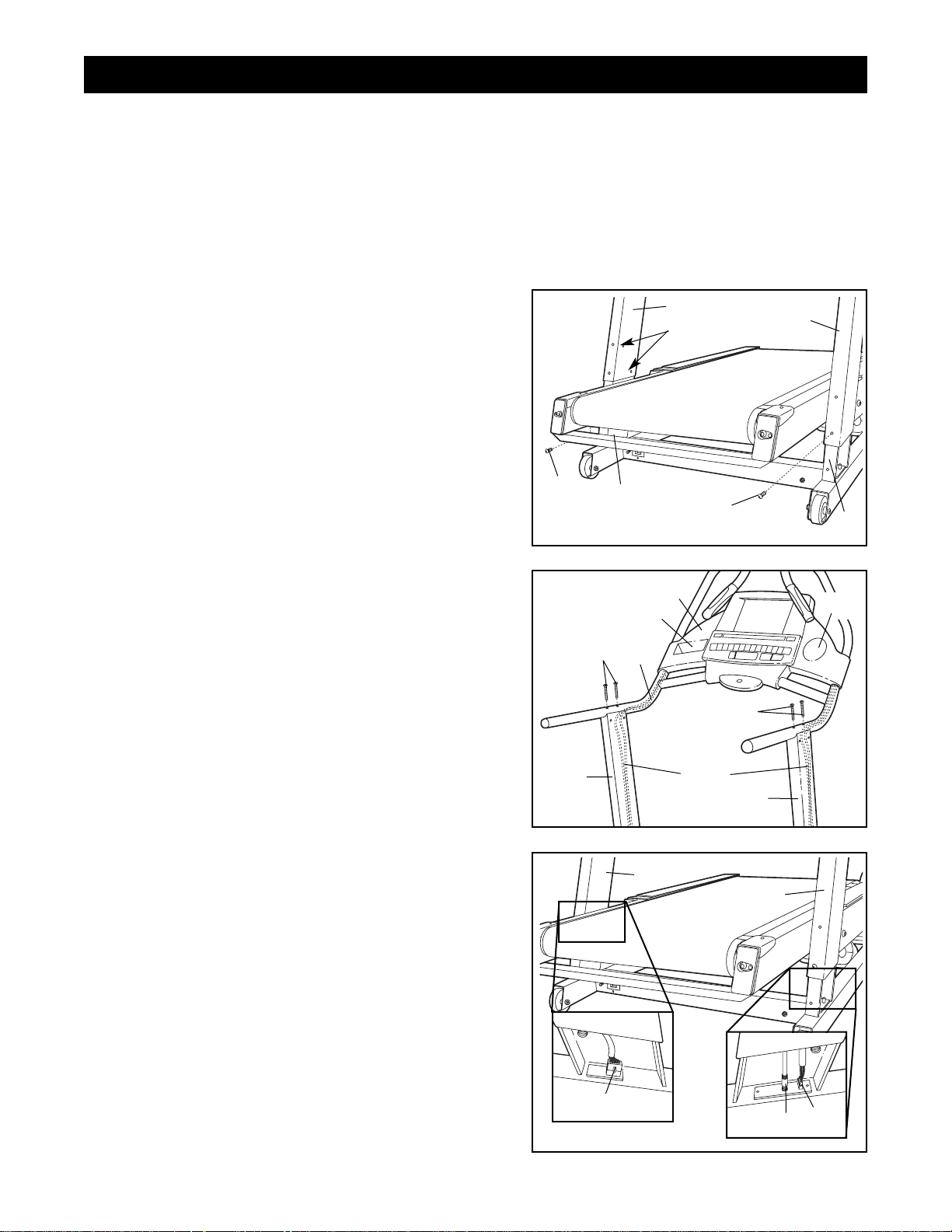
3. Connect the Right Upright Wire Harness (105), the TV
Cable (33), and the Left Upright Wire Harness (131) in
the indicated locations. Push all of the excess wire up
into the Uprights (96, 107). Make sure that all wires are
fully connected. Note: Regardless of which console
your INCLINE TRAINER has, connect all wires so that
the console can later be upgraded if desired.
Refer to step 1. While a second person holds the
Uprights (96, 107), remove the Upright Bolts (106). Slide
the Uprights fully onto the Base Frame (52). Be careful
to avoid pinching your hands or the wires.
2. While a second person holds the Handrail (94) near the
Uprights (96, 107), feed the wires in both sides of the
Handrail down into the Uprights. Pull the ends of the
wires out of the lower ends of the Uprights and remove
the wire ties from the ends of the wires.
Finger tighten four Handrail Bolts (93) into the Handrail
(94) and the Uprights (96, 107) as shown. Be careful to
avoid pinching the wires in the Handrail.
Note: The CD Holder (143) and the Cup Holder (10) are
replaceable. If these parts become dislodged from the
Console (89), simply press them back into place.
94
107
96
93
143
89
10
93
Wires
2
HOW TO SET UP THE INCLINE TRAINER
107
96
105
33
131
3
1. Slide the Right and Left Uprights (96, 107) onto the
brackets near the front of the Base Frame (52). Make
sure that the Uprights are on the correct sides; the
indicated holes must be facing the INCLINE
TRAINER.
Raise the Left Upright (107) until the lower hole in the
front of the Upright is aligned with the upper hole in the
bracket as shown. Thread an Upright Bolt (106) into the
Upright and the bracket. Do not fully tighten the
Upright Bolt yet.
Repeat this step with the Right Upright (96).
107
52
52
Holes
106
106
96
1
8
4. Thread two Upright Bolts (106) into each Upright (96,
107) in the indicated locations. Do not tighten the
Upright Bolts yet.
107
106
106
96
4
5. Next it will be necessary to adjust the incline of the
INCLINE TRAINER. First, plug in the power cord (refer
to page 10). Next, make sure that the on/off circuit
breaker is in the on position (refer to step 2 on page 14).
Place the Key (90) in the Console (89). Press the
QUICK INCLINE button labeled “20” to adjust the incline to 20%. Then, remove the Key.
Move the on/off circuit breaker to the off position
and unplug the power cord.
6. Thread two additional Upright Bolts (106) into each
Upright (96, 107) in the indicated locations. Tighten all
eight Upright Bolts in the Uprights.
7. Refer to step 2 on page 7 and tighten the four Handrail
Bolts (93).
Place the Upright Caps (92) over the Handrail (94) and
the upper ends of the Uprights (96, 107). Press the
Handrail Caps against the hook-and-loop fastener strips
on the Uprights. Attach each Handrail Cap with four
Upright Cap Screws (91). Do not overtighten the
Upright Cap Screws.
90
89
QUICK INCLINE
buttons
107
106
106
106
92
94
91
91
96
107
91
91
96
92
5
6
7
9
HOW TO MOVE THE INCLINE TRAINER
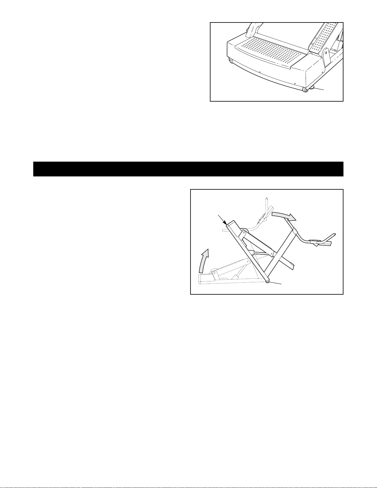
Before moving the INCLINE TRAINER, adjust the
incline to 30% and then unplug the power cord.
Note: It may be necessary to disconnect the CATV
cable and the network wire from the INCLINE
TRAINER, depending on how far the INCLINE
TRAINER will be moved.
Due to the size and weight of the INCLINE
TRAINER, moving it requires two persons. While
one person lifts the indicated end of the INCLINE
TRAINER, firmly hold the handrails and tip the INCLINE TRAINER forward until it rolls on the front
wheels. Carefully move the INCLINE TRAINER to
the desired location and then lower it back to the
level position. Note: Another way to move the INCLINE TRAINER is to have one person stand on
each side of it, lift the frame, and move it on the rear wheels.
CAUTION: To reduce the risk of injury, use extreme caution while moving the INCLINE TRAINER. Do not
attempt to move the INCLINE TRAINER over uneven surfaces.
Lift
Here
Front Wheels
Rear
Wheels
Tip
Handrails
9. Make sure that all parts are properly tightened before you use the INCLINE TRAINER. Keep the included
allen wrenches for adjustment purposes. To protect the floor or carpet from damage, place a mat under the
INCLINE TRAINER.
8. After the INCLINE TRAINER is placed in the location
where it will be used (refer to HOW TO MOVE THE
INCLINE TRAINER below), make sure that both Rear
Feet (66) and both front Wheels (not shown) rest firmly
on the floor. If the INCLINE TRAINER rocks even
slightly, turn the right Rear Foot clockwise or counterclockwise until the rocking motion is eliminated.
66
8
10
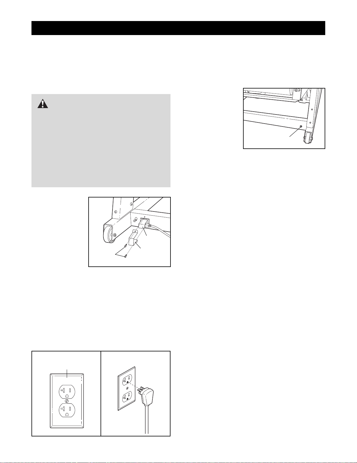
HOW TO CONNECT THE POWER CORD
This product must be grounded. If it should malfunc-
tion or break down, grounding provides a path of least
resistance for electric current to reduce the risk of electric shock.
This product is
for use on a dedicated, 20-amp,
120-volt circuit.
No other appliance should be
on the same circuit. This product
is equipped with
a cord having an
equipmentgrounding
conductor and a grounding plug. Plug one end of the
cord into the INCLINE TRAINER as shown in drawing
1. Attach the cord bracket over the cord with the in-
cluded allen wrench and the two bracket screws.
Plug the grounding plug into a standard NEMA 5-20
receptacle as shown in drawing 2. Do not modify the
plug or the receptacle. Do not use an adapter, a surge
protector, or an extension cord.
HOW TO CONNECT A CATV CABLE
If your INCLINE TRAINER has the Workout TV console, a CATV cable must be connected to the IN-
CLINE TRAINER for cable TV stations to be viewed.
Locate the cable
jack on the front of
the INCLINE
TRAINER.
Connect the CATV
cable to the cable
jack. Route the
cable so that it will
not be pinched or
crushed by the
wheels when the incline is changed.
A satellite receiver, VCR, or DVD player can also be
connected to the INCLINE TRAINER. Connect a CATV
cable from the coaxial output on your equipment (usually labeled TV OUT or RF OUT) to the cable jack on
the front of the INCLINE TRAINER.
Note: Audio/video equipment without coaxial outputs
(some satellite receivers and DVD players) will require
an RF modulator to work correctly with the INCLINE
TRAINER. RF modulators are not available from
FreeMotion Fitness, but are available at electronics
stores. See the owner's manual for the equipment you
wish to connect to determine if an RF modulator is
needed.
DANGER:Improper connection
of the equipment-grounding conductor can
result in an increased risk of electric shock.
Check with a qualified electrician or serviceman if you are in doubt as to whether the
product is properly grounded. Do not modify
the plug provided with the product—if it will
not fit the outlet, have a proper outlet
installed by a qualified electrician. Do not use
an adapter to connect the plug to an improper
receptacle.
HOW TO CONNECT THE INCLINE TRAINER
1
Cord
Cord
Bracket
Bracket
Screws
Cable Jack
NEMA 5-20
Receptacle
1
If your INCLINE TRAINER has the Basic console or
the Workout TV console, you can connect a portable
CD player to the INCLINE TRAINER and use iFIT.com
CD’s. (Refer to page 22 for instructions about using
iFIT.com CD’s.)
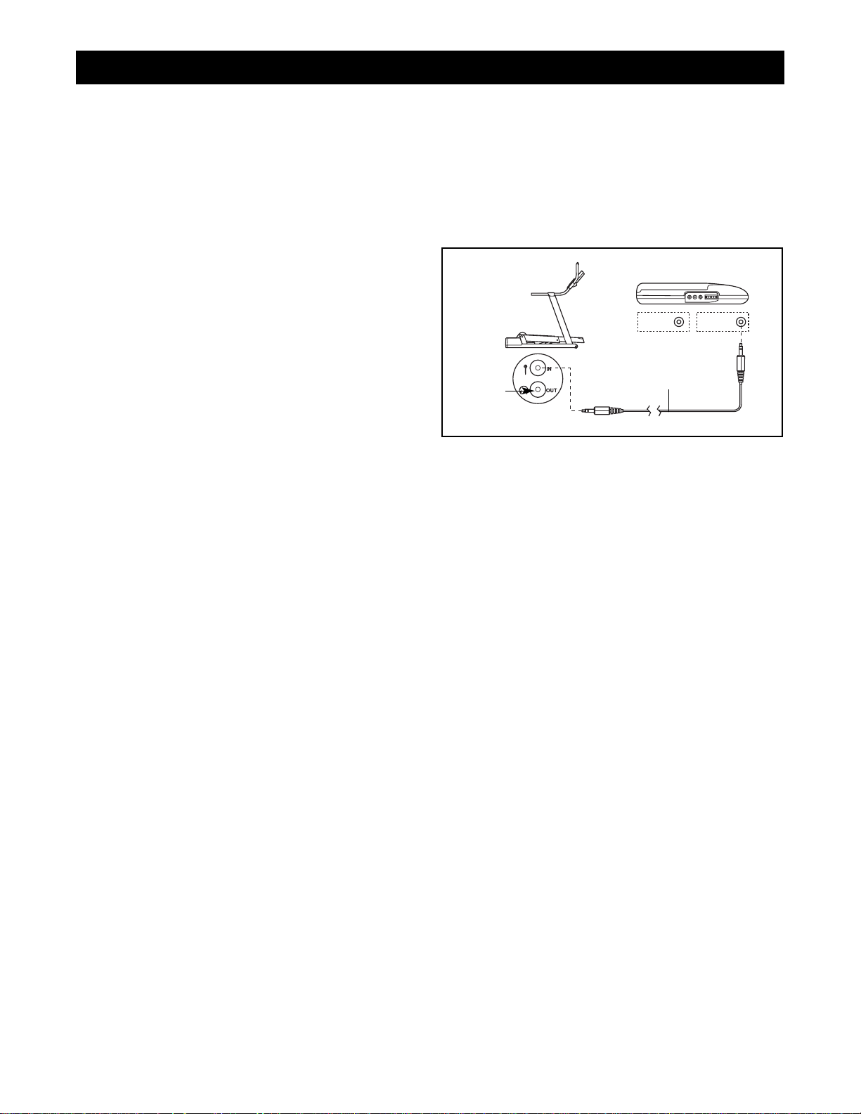
HOW TO CONNECT YOUR PORTABLE CD PLAYER
Plug one end of the included male-to-male audio cable
into the jack on the left side of the console. Plug the
other end of the audio cable into the PHONES jack on
your CD player. Plug your headphones into the jack on
the console.
11
Male-to-Male
Audio Cable
Head-
phones
HOW TO CONNECT YOUR CD PLAYER
LINE OUT
PHONES
LINE OUT
PHONES
12
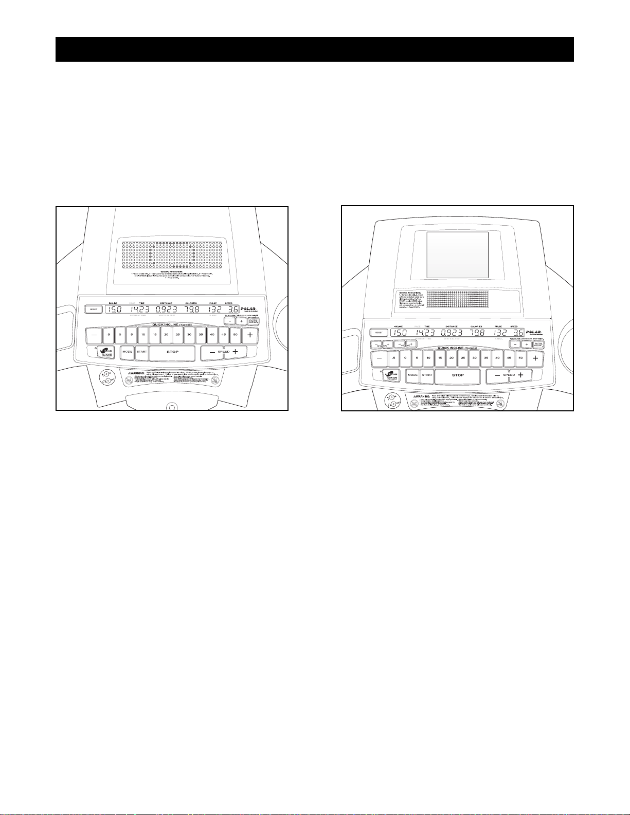
Your INCLINE TRAINER has been pre-configured to operate with the Basic console and the Workout TV console
(see the drawings below).
For information about the features of the Basic console, refer to page 13. To learn about the state-of-the-art
Workout TV console, refer to page 26.
To upgrade your console and expand the capabilities of your INCLINE TRAINER whenever you choose,
simply contact your local FreeMotion Fitness Sales Representative or call FreeMotion Fitness toll-free at
1-877-363-8449.
HOW TO UPGRADE YOUR CONSOLE
Workout
TV Console
Basic Console
13
FEATURES OF THE CONSOLE
The Basic console offers an impressive array of features to help you get the most from your exercise.
When the manual mode of the console is selected, the
speed and incline of the INCLINE TRAINER can be
changed with a touch of a button. As you exercise, the
console will provide continuous exercise feedback.
You can even measure your heart rate using the builtin pulse sensor.
Six preset workout programs are also offered. Each program automatically controls the speed and incline of
the INCLINE TRAINER to give you an effective workout.
In addition, the console offers three pulse-driven programs that adjust the speed and incline of the INCLINE
TRAINER to keep your heart rate near target levels
during your workouts, and a unique fitness test program that measures your relative fitness level. Note:
The pulse-driven programs and the fitness test program require the use of a Polar
®
-compatible chest
pulse sensor (not included).
The console also features new iFIT.com interactive
technology. IFIT.com technology is like having a personal trainer right at your side. Using a male-to-male
audio cable (available at electronics stores), you can
connect your portable CD player to the INCLINE
TRAINER and play special iFIT.com CD programs
(CD’s are available separately). IFIT.com CD programs
automatically control the speed and incline of the
INCLINE TRAINER as a personal trainer guides you
through every step of your workout. High-energy music
provides added motivation. Each CD features two programs designed by certified personal trainers. To order
iFIT.com CD’s, call toll-free 1-877-363-8449.
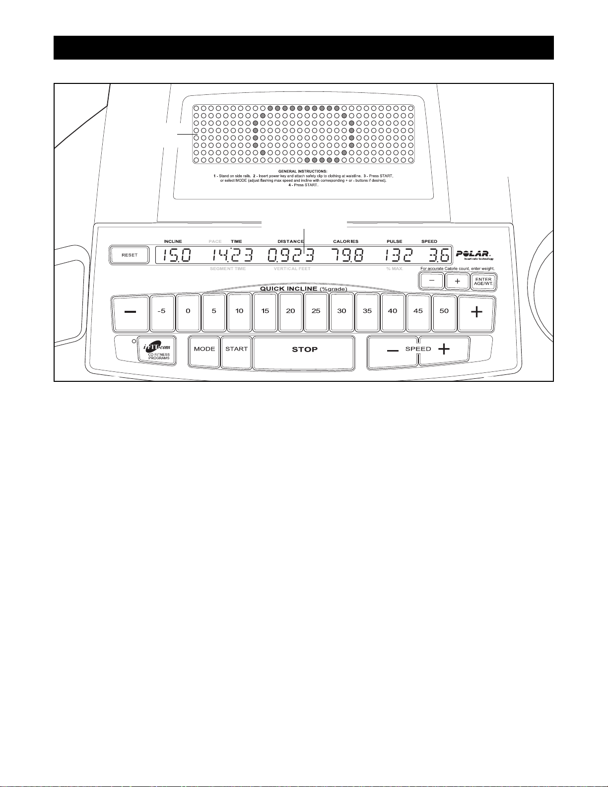
HOW TO USE THE BASIC CONSOLE
Main Display
Matrix
Note: If there is a
thin sheet of clear
plastic on the face
of the console,
remove it.
14
GETTING STARTED
Plug in the power cord.
Refer to HOW TO CONNECT THE POWER
CORD on page 10.
Move the on/off circuit breaker to the on
position.
Locate the on/off
circuit breaker
on the INCLINE
TRAINER near
the power cord.
Switch the on/off
circuit breaker to
the on position.
Insert the key into the console.
Note: The console can be set to be used without
the key. Refer to step 11 on page 24 for instructions. If the console is set to be used without
the key, go to step 4.
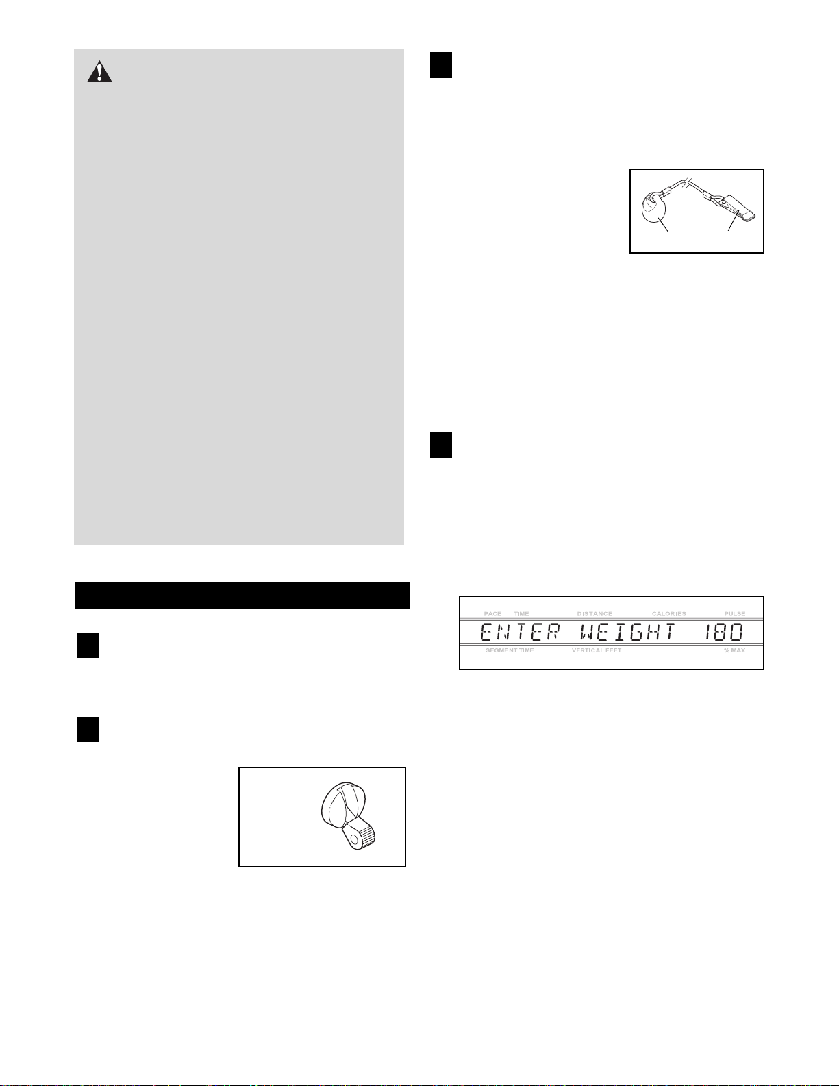
Find the key and the clip
on the console and attach the clip to the waistband of your clothes.
Next, insert the key into
the console. Test the
clip by carefully taking
a few steps backward until the key is pulled
from the console. If the key is not pulled from
the console, adjust the position of the clip as
needed.
Insert the key into the console again. After a moment, various displays and indicators on the console will light.
Enter your weight.
Although you can use the console without entering
your weight, the console will count the Calories
that you burn more accurately if you enter your
weight. To enter your weight, first press the
ENTER AGE/WT button. The words ENTER
WEIGHT and the current weight setting will appear in the main display.
Press the + and – buttons beside the ENTER
AGE/WT button to enter your weight. The buttons
can be held down to enter your weight quickly.
To use the manual mode of the console, follow the
steps beginning on page 15. To use a preset program,
refer to page 17. To use a pulse-driven program,
refer to page 19. To use the fitness test program,
refer to page 20. To use an iFIT.com CD program,
refer to page 22. To use the maintenance mode, refer
to page 23.
4
3
2
1
CAUTION:Before operating the
console, read the following precautions.
• Do not stand on the walking belt when turning on the power.
• Always wear the clip (see the drawing at the
right) while operating the INCLINE TRAINER.
• Adjust the speed in small increments to
avoid sudden jumps in speed.
• The pulse sensor is not a medical device.
Various factors may affect the accuracy of
heart rate readings. The pulse sensor is intended only as an exercise aid in determining heart rate trends in general.
• If you have heart problems, or if you are over
60 years of age and have been inactive, do
not use the pulse-driven programs. If you
are taking medication regularly, consult your
physician to find whether the medication will
affect your exercise heart rate.
• To reduce the possibility of electric shock,
keep the console dry. Avoid spilling liquids
on the console and place only a sealed water
bottle in the water bottle holder.
Key
Clip
“On”
Position

15
HOW TO USE THE MANUAL MODE
Insert the key into the console.
Refer to GETTING STARTED on page 14.
Select the manual mode.
When the key is inserted, the manual mode will
automatically be selected. If a program or the
iFIT.com mode has been selected, press the
MODE button repeatedly until the main display appears as shown below.
Press the START button or the SPEED + button
to start the walking belt.
A moment after the button is pressed, the walking
belt will begin to move at 1 mph. Hold the handrails
and begin walking.
As you exercise,
change the speed of
the walking belt as desired by pressing the
SPEED + and –
buttons. Each time a
button is pressed, the speed setting will change
by 0.1 mph; if a button is held down, the speed
setting will change in increments of 0.5 mph. The
speed range is 0.5 mph to 8 mph. (When the incline setting is 20% or higher, the speed range is
0.5 mph to 6 mph.) Note: After the buttons are
pressed, it may take a moment for the INCLINE
TRAINER to reach the selected speed setting.
To stop the walking belt, press the STOP button.
The time will begin to flash in the main display. To
restart the walking belt, press the START button or
the SPEED + button and then adjust the speed as
desired.
Change the incline of the INCLINE TRAINER as
desired.
To change the incline of
the INCLINE TRAINER,
press the INCLINE +
and – buttons. Each
time a button is
pressed, the incline will change by 0.5%. To
change the incline quickly, press the QUICK INCLINE buttons. The incline range is -5% to 50%.
Note: After the buttons are pressed, it may take a
moment for the INCLINE TRAINER to reach the selected incline setting.
Follow your progress with the matrix and the
main display.
The matrix—When
the manual mode or
the iFIT.com mode is
selected, the matrix
will display a 1/4-mile
track. As you exercise, the indicators
around the track will light in sequence to show your
position on the track. Each time you complete a
1/4-mile lap, a new lap will begin.
The main display—The main display will show
the following information:
Incline—The left end of
the main display will
show the incline level of
the INCLINE TRAINER.
Pace/Time—When the
manual mode or the
iFIT.com mode is selected, this section of the
main display will show
the elapsed time. When
a preset program or a pulse-driven program is selected, the display will show the time remaining in
the program and the time remaining in the current
segment of the program. The display will change
from one number to the other every seven seconds. During the fitness test program, the display
will show the elapsed time and the time remaining
in the current segment of the program. Note: Any
time that the speed setting changes, the display
will show your current pace (in minutes per mile)
for seven seconds.
Distance/Vertical
Feet—The center sec-
tion of the main display
will show the distance
that you have walked
and the number of vertical feet you have climbed. The display will change
from one number to the other every seven seconds.
5
4
3
2
1

16
Calories—This section
of the main display will
show the approximate
number of Calories you
have burned.
Pulse/% Max—When
you are using the
handgrip pulse sensor
or a Polar
®
-compatible
chest pulse sensor (not
included), this section
of the main display will show your heart rate (refer
to step 6). When a pulse-driven program is selected, the display will show your heart rate and
the corresponding percentage of your estimated
maximum heart rate. (Refer to step 5 on page 19
for an explanation of your estimated maximum
heart rate.) The display will change from one number to the other every seven seconds.
Speed—The right end
of the main display will
show the speed of the
walking belt.
To reset the displayed time, distance, vertical feet,
and Calories at any time, press the RESET
button.
Measure your heart rate if desired.
To measure your
heart rate, stand
on the foot rails
and hold the handgrip pulse sensor
with both hands.
Your palms must
be resting on the
upper contacts and
your fingers must
be touching the
lower contacts—
avoid moving your
hands. When your pulse is detected, the words
ACQUIRING PULSE will appear in the main display and then your heart rate will be shown. For
the most accurate heart rate reading, continue
to hold the contacts for at least 15 seconds.
When you are finished exercising, stop the
walking belt and remove the key.
Step onto the foot rails and press the STOP
button. Next, remove the key from the console and
put the key in a secure place.
When the INCLINE TRAINER is not in use, switch
the on/off circuit breaker near the power cord to
the off position and unplug the power cord.
7
6
Sensors

17
HOW TO USE PRESET PROGRAMS
Insert the key into the console.
Refer to GETTING STARTED on page 14.
Select one of the six preset programs.
When the key is inserted, the manual mode will
automatically be selected. To select one of the six
preset programs, press the MODE button repeatedly until the words MOOSE TRACKS, SLICKROCK, MOAB RIM, SWITCHBACK, TETON
CREST, or ALTA ADVENTURE appear in the
main display. Note: MOOSE TRACKS is a level
one (low-intensity) walking program; SLICKROCK
is a level one running program; MOAB RIM is a
level two (medium-intensity) walking program;
SWITCHBACK is a level two running program;
TETON CREST is a level three (high-intensity)
walking program; and ALTA ADVENTURE is a
level three running program.
When a preset program is selected, the maximum
incline setting for the program will flash at the left
end of the main display and the maximum speed
setting will flash at the right end. After three seconds, the name of the selected program, the level
of the program, and the total program time will
begin to scroll across the main display. If desired,
you can change the maximum incline setting or
the maximum speed setting by pressing the INCLINE or SPEED buttons. If you increase either
setting, the difficulty level of the entire program
will increase; if you decrease either setting, the
difficulty level of the entire program will decrease.
When a preset program is selected, the
matrix will show a
graph representing
the incline settings
for the program.
Press the START button or the SPEED + button
to start the program.
A moment after the button is pressed, the INCLINE TRAINER will automatically adjust to the
first incline and speed settings for the program.
Hold the handrails and begin walking.
Each program is divided into several time segments
of different lengths. The main display will show
both the time remaining in the program and the
time remaining in the current segment of the program. One incline setting and one speed setting
are programmed for
each segment. The
incline setting for the
first segment is
shown in the flashing
CURRENT SEGMENT column of the
matrix. (The speed
settings are not
shown in the matrix.) The incline settings for upcoming segments are shown in the columns to the
right.
When only three seconds remain in the first segment of the program, both the CURRENT SEGMENT column and the column to the right will
flash, a series of tones will sound, and all incline
settings will move one column to the left. The incline setting for the second segment will then be
shown in the flashing CURRENT SEGMENT column and the INCLINE TRAINER will automatically
adjust to the incline and speed settings for the second segment. The program will continue until the
incline setting for the final segment is shown in the
CURRENT SEGMENT column and no time remains in the program. The walking belt will then
slow to a stop.
Note: Each time a segment ends and the incline
settings move to the left, if all of the indicators in
the CURRENT SEGMENT column are lit, the incline settings may move downward so that only the
highest indicators in the columns appear in the matrix. When the incline settings move to the left
again, if not all of the indicators in the CURRENT
SEGMENT column are lit, the incline settings will
move back up.
Note: You can manually override the incline or
speed setting for the current segment by pressing
the INCLINE or SPEED buttons. Every few times
an INCLINE button is pressed, an additional indicator will light or darken in the CURRENT SEGMENT column. (If any of the columns to the right
of the CURRENT SEGMENT column have the
same number of lit indicators as the CURRENT
SEGMENT column, an additional indicator may
light or darken in those columns as well.) If you
manually adjust the incline setting so that all of the
indicators in the CURRENT SEGMENT column
are lit, the incline settings in the matrix will not
move downward as described above. Important:
When the next segment of the program begins,
the INCLINE TRAINER will automatically adjust
3
2
1
CURRENT SEGMENT

18
to the incline and speed settings for the next
segment.
To stop the program, press the STOP button. The
time will begin to flash in the main display. To
restart the program, press the START button or the
SPEED + button. The walking belt will begin to
move at 1 mph. When the next segment of the program begins, the INCLINE TRAINER will automatically adjust to the incline and speed settings for the
next segment.
Follow your progress with the main display.
Refer to step 5 on page 15.
Measure your heart rate if desired.
Refer to step 6 on page 16.
When the program is completed, remove the
key.
Step onto the foot rails. Remove the key from the
console and put the key in a secure place.
When the INCLINE TRAINER is not in use, switch
the on/off circuit breaker near the power cord to
the off position and unplug the power cord.
6
5
4

19
HOW TO USE PULSE-DRIVEN PROGRAMS
Pulse-driven programs automatically control the incline
and speed of the INCLINE TRAINER to keep your
heart rate near a target level while you exercise.
Follow the steps below to use a pulse-driven program.
Put on a Polar
®
-compatible chest pulse sensor
(not included).
You must wear a chest pulse sensor to use a
pulse-driven program. Refer to the instructions
included with your chest pulse sensor.
Insert the key into the console.
Refer to GETTING STARTED on page 14.
Select one of the three pulse-driven programs.
When the key is inserted, the manual mode will be
selected. To select one of the three pulse-driven
programs, press the MODE button repeatedly until
the words MOAB RIM PULSE, SLICKROCK
TRAIL PULSE, or MANUAL PULSE appear in the
main display. Note: The MOAB RIM PULSE program will keep your heart rate near 65% of your
estimated maximum heart rate (refer to step 5 at
the right for an explanation of your estimated maximum heart rate). The SLICKROCK TRAIL
PULSE program will keep your heart rate near
80% of your estimated maximum heart rate. The
MANUAL PULSE program will keep your heart
rate near a percentage that you select.
When a pulse-driven program is selected, the
name of the selected program and the total program time will scroll across the main display. The
words ENTER AGE and the current age setting
will then be shown.
During pulse-driven
programs, the matrix
will show a moving
graphic that represents your heart rate.
Each time a heartbeat is detected, an
additional peak will appear in the graphic.
Enter your age.
You must enter your age to use a pulse-driven
program. To enter your age, press the + and – but-
tons beside the ENTER AGE/WT button. The buttons can be held down to enter your age quickly.
The age range is 20 to 80 years. When your age is
shown, press the ENTER AGE/WT button.
If you have selected the MOAB RIM PULSE or
SLICKROCK TRAIL PULSE program, go to
step 6. If you have selected the MANUAL
PULSE program, go to step 5.
Enter a target heart rate setting.
After you have entered your age, the words
ENTER PERCENT and the target heart rate setting for the program will be shown in the main display. The target heart rate setting represents a
percentage of your estimated maximum heart
rate. Your estimated maximum heart rate is 220
minus your age. For example, if you are 30 years
old, your estimated maximum heart rate is 190
beats per minute (220 – 30 = 190). If you are 30
years old, a target heart rate setting of 50 is equal
to 95 beats per minute (50% of 190 is 95).
If desired, you can change the target heart rate
setting by pressing the + and – buttons beside the
ENTER AGE/WT button. The buttons can be held
down to change the target heart rate setting
quickly. The target heart rate setting can be from
50% to 85% of your estimated maximum heart rate.
Press the START button or the SPEED + button
to start the program.
A moment after the button is pressed, the INCLINE TRAINER will automatically adjust to the
first incline and speed settings for the program.
Hold the handrails and begin walking.
6
5
4
3
2
1

20
Each pulse-driven program is divided into oneminute segments. (The main display will show both
the time remaining in the program and the time remaining in the current segment of the program.)
One target heart rate setting is programmed for
each segment. (During the MANUAL PULSE program, the same target heart rate setting will be
programmed for all segments.)
When only three seconds remain in the first segment of the program, a series of tones will sound
and the incline and/or speed of the INCLINE
TRAINER will change, if needed, to bring your
heart rate closer to the target heart rate setting for
the next segment. The incline and/or speed setting
will flash in the main display to alert you before the
speed and/or incline changes. The program will
continue until no time remains in the program. The
walking belt will then slow to a stop.
If the incline or speed setting for the current segment is too high or too low, you can adjust the setting with the INCLINE or SPEED buttons.
However, if you decrease the incline, the speed
will automatically increase; if you increase the incline, the speed will decrease. If you increase the
speed, the incline will decrease; if you decrease
the speed, the incline will increase. The INCLINE
TRAINER will always attempt to keep your heart
rate near the target heart rate setting for the current segment. Note: When the incline reaches the
lowest setting, the speed cannot be increased any
further. When the incline reaches the highest setting, the speed cannot be decreased any further.
If your pulse is not detected during the program,
the letters PLS will flash in the main display and
the incline and speed of the INCLINE TRAINER
may automatically decrease until your pulse is detected. If this occurs, refer to the instructions included with your chest pulse sensor.
To stop the program at any time, press the STOP
button. Pulse-driven programs should not be
stopped temporarily and then restarted. To use a
pulse-driven program again, reselect the program
and start it at the beginning.
Follow your progress with the main display.
Refer to step 5 on page 15.
When the program is completed, remove the
key.
Refer to step 6 on page 18.
HOW TO USE THE FITNESS TEST PROGRAM
The fitness test program measures your relative fitness
level. For the best results, the program should be used
at a time when your energy level is high; the program
should not be used if you have already exercised during the day. Follow the steps below to use the program.
Put on a Polar
®
-compatible chest pulse sensor
(not included).
You must wear a chest pulse sensor to use the
fitness test program. Refer to the instructions in-
cluded with your chest pulse sensor.
Insert the key into the console.
Refer to GETTING STARTED on page 14.
Select the fitness test program.
When the key is inserted, the manual mode will be
selected. To select the fitness test program, press
the MODE button repeatedly until the words FITNESS TEST appear in the main display.
When the fitness test program is selected, the
words FITNESS TEST will scroll across the main
display. The words ENTER AGE and the current
age setting will then be shown.
During fitness test
program, the matrix
will show a moving
graphic that represents your heart rate.
Each time a heartbeat is detected, an
additional peak will appear in the graphic.
Enter your age.
You must enter your age to use the fitness test
program. To enter your age, refer to step 4 on
page 19.
4
3
2
1
8
7

21
Press the START button or the SPEED + button
to start the program.
When the button is pressed, the main display will
show the words LEVEL 1, indicating that the first
four-minute level of the fitness test program has
begun. The incline of the INCLINE TRAINER will
automatically adjust to 3% and the walking belt
will begin to move at 1.5 mph. Hold the handrails
and begin walking.
The fitness test program is divided into seven,
four-minute levels. One incline setting and one
speed setting are programmed for each level.
At the end of each minute of the program, a tone
will sound. When the first four-minute level is completed, a tone will sound and the main display will
show the words LEVEL 2, indicating that the second four-minute level has begun. The incline will
then change to 4% and the speed of the walking
belt will increase to 2.5 mph.
At the beginning of each four-minute level, the
speed and/or incline of the INCLINE TRAINER will
automatically increase. The fitness test program
will continue in this way until your heart rate
reaches 70% of your estimated maximum heart
rate and the current four-minute level is completed.
The fitness test program will then end, regardless
of how many levels remain.
When the fitness test program is completed, the
word COOL-DOWN will be shown in the main dis-
play and a two-minute cool-down period will begin.
The incline and speed will then decrease.
When the cool-down period is completed, the
walking belt will slow to a stop and your fitness
level will be shown in the main display. There are
ten fitness levels; fitness level 10 is the highest.
Note: The INCLINE and SPEED buttons will not
function while the fitness test program is selected. If
your pulse is not detected during the program, the
letters PLS will flash in the main display. If your
pulse is not detected at the end of any four-minute
level, the fitness test program will end and the
main display will show a fitness level of 0.
The fitness test program cannot be stopped temporarily and then restarted. However, the program
can be stopped at any time with the STOP button.
The main display will then show an estimated fitness level.
When the program is completed, remove the
key.
Refer to step 6 on page 18.
6
5

22
HOW TO USE IFIT.COM CD PROGRAMS
To use iFIT.com CD’s, your portable CD player
must be connected to the INCLINE TRAINER. See
HOW TO CONNECT YOUR CD PLAYER on page 11.
Follow the steps below to use an iFIT.com CD program.
Insert the key into the console.
Refer to GETTING STARTED on page 14.
Select the iFIT.com mode.
When the key is inserted, the manual
mode will be selected.
To select the iFIT.com
mode, press the
IFIT.COM button. The indicator beside the button will light.
Insert an iFIT.com CD.
Insert the iFIT.com CD into your CD player.
Press the PLAY button on your CD player.
A moment after the button is pressed, a recorded
personal trainer will begin guiding you through
your workout. Simply follow the personal trainer’s
instructions. Note: If the time is flashing in the
main display, press the START button or the
SPEED + button on the console. The INCLINE
TRAINER will not respond to a CD program while
the time is flashing.
During the CD program, an electronic “chirping”
sound will alert you when the speed and/or incline
of the INCLINE TRAINER is about to change.
CAUTION: Always listen for the “chirp” and be
prepared for speed and/or incline changes. In
some instances, the speed and/or incline may
change before the personal trainer describes
the change.
If the speed or incline settings are too high or too
low, you can manually override the settings at any
time by pressing the SPEED or INCLINE buttons
on the console. However, when the next “chirp”
is heard, the speed and/or incline will change
to the next settings of the CD program.
To stop the walking belt at any time, press the
STOP button on the console. The time will begin
to flash in the main display. To restart the program, press the START button or the SPEED +
button. After a moment, the walking belt will begin
to move at 1 mph. When the next “chirp” is
heard, the speed and incline will change to the
next settings of the CD program. The program
can also be stopped by pressing the STOP button
on your CD player.
When the CD program is completed, the walking
belt will stop and the time will begin to flash in the
main display. Note: To use another CD program,
press the STOP button or remove the key and go
to step 1.
Note: If the speed or incline of the INCLINE
TRAINER does not change when a “chirp” is
heard:
• Make sure that the iFIT.com indicator is lit and
that the time is not flashing in the main display. If the time is flashing, press the START
button or the SPEED + button on the console.
• Adjust the volume of your CD player. If the
volume is too high or too low, the console
may not detect the program signals.
• Make sure that the audio cable is properly
connected, that it is fully plugged in, and that
it is not wrapped around a power cord.
Follow your progress with the main display.
Refer to step 5 on page 15.
Measure your heart rate, if desired.
Refer to step 6 on page 16.
When the program is completed, remove the
key.
Refer to step 6 on page 18.
7
6
5
4
3
2
1

HOW TO USE THE MAINTENANCE MODE
The console features a maintenance mode that allows
you to access information and to view and change various default settings. Follow the steps below to use the
maintenance mode.
Insert the key into the console.
Refer to GETTING STARTED on page 14.
Hold down the ENTER AGE/WT button and the
RESET button simultaneously for two seconds
to select the maintenance mode.
When the maintenance mode is selected, the
words MAINTENANCE MODE will appear in the
main display.
Press the ENTER AGE/WT button to view the
total number of hours that the INCLINE
TRAINER has been used.
Press the ENTER AGE/WT button again to
view the total distance that the walking belt
has moved.
Press the ENTER AGE/WT button again and
set the delay time for the timeout mode.
Any time that the INCLINE TRAINER is not used
for several minutes, the console will enter a timeout mode and the words PUSH ANY BUTTON TO
START A NEW PROGRAM will begin to scroll
across the main display. To set the number of minutes before the console will enter the timeout
mode, press the + and – buttons beside the
ENTER AGE/WT button. The delay time can be
from 1 to 15 minutes.
Press the ENTER AGE/WT button again and
set the program time for MOOSE TRACKS,
MOAB RIM, and TETON CREST programs.
The MOOSE TRACKS, MOAB RIM, and TETON
CREST programs can be set to last for 20, 30, or
40 minutes. To change the setting, press the +
and – buttons beside the ENTER AGE/WT button.
Press the ENTER AGE/WT button again and set
the program time for the SLICKROCK, SWITCHBACK, and ALTA ADVENTURE programs.
The SLICKROCK, SWITCHBACK, and ALTA ADVENTURE programs can be set to last for 20, 30,
or 40 minutes. To change the setting, press the +
and – buttons beside the ENTER AGE/WT button.
Press the ENTER AGE/WT button again to
check for controller errors.
If there are no controller errors, the words NO
CONTROLLER ERRORS will appear in the main
display. If there is a controller error, the name of
the error will appear in the main display. If this occurs, press the RESET button. If the same controller error appears repeatedly, call Customer
Care toll-free at 1-800-201-2109.
8
7
6
5
4
3
2
1
23

24
Press the ENTER AGE/WT button again to
check for system errors.
If there are no system errors, the words NO SYSTEM ERRORS will appear in the main display. If
the words LUBRICATE DECK appear in the main
display, the walking platform should be checked
for adequate lubricant. Follow the instructions in
step 4 on page 29 to lubricate the walking platform
if necessary. Then, refer to HOW TO RESET THE
LUBE REMINDER on page 25. If the words INCLINE OVERHEAT ERROR appear in the main
display, press the RESET button. If the same system error appears repeatedly, call Customer Care
toll-free at 1-800-201-2109.
Press the ENTER AGE/WT button again and
enable or disable the lubrication reminder.
The console can be set to display the words LUBRICATE DECK every five minutes when the
walking platform needs to be lubricated. Press the
+ or – button beside the ENTER AGE/WT button
until the words LUBE REMINDER ENABLED appear in the main display. To turn off the lubrication
reminder, press the + or – button until the words
LUBE REMINDER DISABLED appear.
Press the ENTER AGE/WT button again and
enable or disable the safety key.
To require the use of the safety key with the console, press the + or – button beside the ENTER
AGE/WT button until the words SAFETY KEY ENABLED appear in the main display. To allow the
INCLINE TRAINER to be used without the key,
press the + or – button until the words SAFETY
KEY DISABLED appear. CAUTION: If the safety
key is missing or damaged, call Customer Care
toll-free at 1-800-201-2109, Monday through
Friday, 8 a.m. until 5 p.m. Mountain Time.
If you have the Basic console, go to step 16. If
you have the Workout TV console, go to step
12.
Press the ENTER AGE/WT button again and
enable or disable the TV.
To make the TV available for use, press the + or –
button beside the ENTER AGE/WT button until the
words TV POWER ON appear in the main display.
To prevent the TV from being used, press the + or
– button until the words TV POWER OFF appear.
If you have disabled the TV, go to step 16. If
you have enabled the TV, go to step 13.
Press the ENTER AGE/WT button again and
select a cable TV connection or an antenna
connection.
If you are using a cable TV connection, press the +
or – button beside the ENTER AGE/WT button
until the words TV MODE CABLE STATIONS appear in the main display. If you are using an antenna connection, press the + or – button until the
words TV MODE AIR STATIONS appear.
Press the ENTER AGE/WT button again and
program TV channels.
The console has the capability to find and store in
memory all of the valid TV channels in your area.
While the words PRESS CHANNEL UP TO SCAN
TV CHANNELS are scrolling across the main display, press the CHANNEL + button to start the
channel scanning process.
9
10
11
12
13
14

The console will begin scanning all TV channels. If
no broadcast signal is detected on a channel, the
channel will be skipped; if a signal is detected, a
tone will sound and the channel will be stored in
memory. This process will continue until the highest channel is reached. The lowest channel stored
in memory will then appear in the main display.
Press the ENTER AGE/WT button again and
delete or add TV channels.
After all valid TV channels have been stored in the
console’s memory, you can delete unwanted
channels or add other channels. To delete or add
a channel, first press the CHANNEL + and – buttons until the channel appears in the main display.
Next, press the + or – button beside the ENTER
AGE/WT button until the words DELETE or ADD
appear in the main display. Then, select the next
channel that you want to delete or add. Repeat
this process until you have finished deleting or
adding channels.
Hold down the ENTER AGE/WT button and the
RESET button simultaneously for two seconds
to exit the maintenance mode.
To exit the maintenance mode at any time, hold
down the ENTER AGE/WT button and the RESET
button simultaneously for two seconds.
HOW TO RESET THE LUBE REMINDER
If the words LUBRICATE DECK appear in the main
display when the maintenance mode is selected (refer
to step 9 on page 24), follow the steps below to reset
the lube reminder.
Insert the key into the console.
Refer to GETTING STARTED on page 14.
Hold down the STOP button and the RESET
button simultaneously for three seconds.
2
1
15
16
25
26
FEATURES OF THE CONSOLE
The state-of-the-art Workout TV console offers an impressive array of features to make your workouts more
effective and enjoyable.
When the manual mode of the console is selected, the
speed and incline of the INCLINE TRAINER can be
changed with a touch of a button. As you exercise, the
console will provide instant exercise feedback. You can
even measure your heart rate using the built-in pulse
sensor.
Six preset workout programs are also offered. Each program automatically controls the speed and incline of
the INCLINE TRAINER to give you an effective workout.
In addition, the console offers three pulse-driven programs that adjust the speed and incline of the INCLINE
TRAINER to keep your heart rate near target levels
during your workouts, and a unique fitness test program that measures your relative fitness level. Note:
The pulse-driven programs and the fitness test program require the use of a Polar
®
-compatible chest
pulse sensor (not included).
No matter which mode or program you select, the personal TV will allow you to watch the television program
of your choice while you exercise.
The console also features new iFIT.com interactive
technology. IFIT.com technology is like having a personal trainer right at your side. Using a male-to-male
audio cable (available at electronics stores), you can
connect your portable CD player to the INCLINE
TRAINER and play special iFIT.com CD programs
(CD’s are available separately). IFIT.com CD programs
automatically control the speed and incline of the
INCLINE TRAINER as a personal trainer guides you
through every step of your workout. High-energy music
provides added motivation. Each CD features two programs designed by certified personal trainers. To order
iFIT.com CD’s, call toll-free 1-877-363-8449.
To upgrade your INCLINE TRAINER with the
Workout TV console, call toll-free 1-877-363-8449.
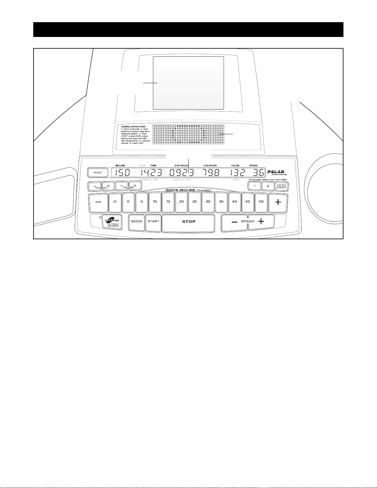
HOW TO USE THE WORKOUT TV CONSOLE
Main Display
Matrix
Flat Screen
Television
Note: If there is a
thin sheet of clear
plastic on the face
of the console,
remove it.

27
HOW TO USE THE WORKOUT TV CONSOLE
The Workout TV console offers exactly the same features as the Basic console, but incorporates a built-in
personal TV in addition. Note: The console has the capability to find and store in memory all of the valid TV
channels in your area. You can even screen out unwanted channels. Refer to pages 23 to 25 for instructions.
Note: A CATV cable must be connected to the INCLINE TRAINER in order for cable TV stations to
be viewed. Refer to HOW TO CONNECT A CATV
CABLE on page 10 for instructions.
To use the Workout TV console, follow the instructions on pages 14 to 25 of this manual. To use the
personal TV, follow the instructions below.
Select the desired channel.
Press the CHANNEL + and – buttons to select a
channel. The selected channel will appear in the
main display.
Note: If a satellite receiver, VCR, or DVD player is
connected, the channel must be changed at the
satellite receiver, VCR, or DVD player.
Put on headphones (not included) if desired.
To listen to television
programs using headphones, plug your
headphones into the
indicated jack on the
left side of the console.
Adjust the volume.
Press the VOLUME + and – buttons to select the
desired volume. The selected volume setting will
appear in the main display.
3
2
1
Jack

28
NOTES

29
Regular maintenance is necessary for the optimal performance and long life of the INCLINE TRAINER.
Please read and follow all instructions below. If the INCLINE TRAINER is not maintained as described,
components may wear excessively, the INCLINE TRAINER may be damaged, and the warranty will be
voided. If you have questions about maintenance, call Customer Care toll-free at 1-800-201-2109, Monday
through Friday, 8 a.m. until 5 p.m. Mountain Time (excluding holidays). CAUTION: Make sure to remove the key
and unplug the power cord before performing any maintenance procedures.
WEEKLY MAINTENANCE
1. Unplug the power cord. Inspect and properly tighten all external parts of the INCLINE TRAINER.
2. Apply a mild multi-purpose cleaner to a 100% cotton cloth and remove any dust and grime from the handrails,
uprights, foot rails, frame, and motor hood. In addition, wipe the walking platform along the sides of the walking belt. Do not wipe under the walking belt. Apply a small amount of mild multi-purpose cleaner to a 100%
cotton cloth and wipe the console and the screens. Do not spray cleaner directly onto the INCLINE
TRAINER or use ammonia or acid-based cleaners.
3. Make sure that the walking belt is centered and properly tightened. If it is centered and runs smoothly, do not
make any adjustments. If the walking belt needs to be adjusted, refer to pages 33 and 34.
MONTHLY MAINTENANCE
1. Unplug the power cord. Remove the screws attaching the
motor hood and lift off the motor hood. Using a hand-held
vacuum, clean the area under the electronics cover. Be care-
ful to avoid touching any components.
2. Plug in the power cord and insert the key into the console.
Raise the INCLINE TRAINER to the highest incline level.
Remove the key and unplug the power cord. Check the
motor belt for wear and cracks. If the motor belt needs to be replaced, refer to page 46 to order a new motor belt.
3. Plug in the power cord and insert the key into the console. Press the START button. Be careful to avoid in-
jury; keep your hands away from moving parts and make sure that your clothes cannot become
caught in moving parts. While the walking belt is moving, check the motor for arcing. Next, check the IN-
CLINE TRAINER for unusual noises or odors. If any of these problems exists, call Customer Care toll-free at
1-800-201-2109. Remove the key and unplug the power cord. Reattach the motor hood with the screws.
4. The walking platform should not be lubricated before the
INCLINE TRAINER is used. However, lubricant should be
applied at least once every month. To purchase a lubricant
pump or lubricant packets, call Customer Care toll-free at
1-800-201-2109. CAUTION: Before applying lubricant,
remove the key and unplug the power cord.
To use a lubricant pump, first prime the pump. Insert the
wand under the walking belt in the location shown by dotted
line A. Center the nozzles under the walking belt and apply
lubricant as you slide the wand forward to dotted line B. Then,
pull the wand back out. To use lubricant packets, open one
packet, reach under one side of the walking belt as far as you
can, and apply the entire packet between dotted line A and dotted line B. Then, apply a second packet under
the opposite side of the walking belt in the same way. After you have applied lubricant using a lubricant
pump or lubricant packets, plug in the power cord, insert the key, adjust the speed to 3 mph, and walk
on the walking belt for two minutes to spread the lubricant.
PREVENTIVE MAINTENANCE
Apply
packet
here
Insert
wand
here
Motor
Belt
Electronics Cover
A
B

30
TURNING THE WALKING PLATFORM
Both sides of the walking platform are designed to be used as walking surfaces. Inspect the walking platform periodically for wear. If there is any wood showing through the phenolic coating, or if the surface is damaged, the
walking platform should be turned over. The walking platform will need to be turned over after every 6,000 to
7,500 miles. Follow the instructions below to turn over the walking platform.
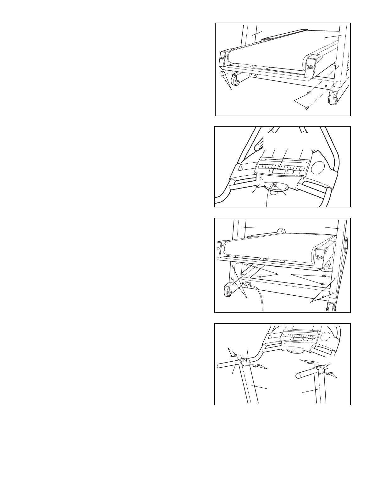
1. Remove the key and unplug the
power cord. Remove the Front
Endcap Screws (15), the Screws
(24), and the Left and Right Front
Endcaps (64, 18). Remove the
Roller Adjustment Bolt (16) and
Washer (17) from each side of the
Front Roller (31).
2. Remove the six Platform Screws
(8). (Note: Be very careful to
avoid chipping or damaging the
phenolic coating on the Walking
Platform (21). Lift the Front Roller
(31) and slide it out of the Walking
Belt (20). Lift the Walking Platform
and the Walking Belt to the position shown by the dotted lines.
Slide the Walking Platform out of
the Walking Belt, turn it, and then
slide it back into the Walking Belt.
3. Lay down the Walking Platform
(21) and the Walking Belt (20). Slide the Front Roller (31) back into the Walking Belt. Look under the Walking
Platform and make sure that the Front Roller Guards (121) are between the Walking Belt and the Walking
Platform (see the inset drawing).
4. Reattach the six Platform Screws (8). Thread the Roller Adjustment Bolts (16) with the Washers (17) into the
Roller (31). Reattach the Front Endcaps (64, 18) with the Endcap Screws (15).
5. Next, the Walking Belt (20) will need to be adjusted to the
proper tension. Using chalk, make two marks on the Walking
Belt exactly 50” apart, as shown in the drawing. Tighten both
Roller Adjustment Bolts (16, shown in the drawing above)
until the two chalk marks move apart an additional 3/16” to
1/4”. Make sure to keep the Walking Belt centered.
REPLACING THE WALKING PLATFORM
When both sides of the walking platform become worn, the walking platform should be replaced. The walking
platform will need to be replaced after every 12,000 to 15,000 miles. Refer to page 46 to order a new walking platform. Follow the instructions above to replace the walking platform.
REPLACING THE WALKING BELT
When the walking belt becomes worn, it should be replaced. The walking belt will need to be replaced after every
12,000 to 15,000 miles. Refer to page 46 to order a new walking belt.
15
31
64
24
8
17
8
8
16
20
21
20
18
21
8
5
1–4
Bottom View
121
20
50”

31
Photocopy this form and use it to record the preventive maintenance performed on the INCLINE TRAINER. Each
copy of the form can be used for six months (26 weeks). When maintenance is performed, write the date in the appropriate spaces. Make sure to perform each maintenance procedure as described on pages 29 and 30. If
the procedures are not performed as described, components may wear excessively, the INCLINE TRAINER
may be damaged, and the warranty will be voided. Note: A copy of this form is found on page 32.
Weekly Maintenance
Inspect and
tighten all external parts of
the INCLINE
TRAINER.
/ /
/ /
/ /
/ /
/ /
/ /
/ / / /
/ /
/ / / /
/ /
/ / / / / / / /
/ / / /
/ /
/ / / /
/ /
/ / / /
/ /
/ / / /
/ /
/ / / / / / / /
/ / / /
/ /
/ / / /
/ /
/ / / /
/ /
/ / / /
/ /
/ / / /
/ /
/ / / / / / / /
/ / / /
/ /
/ / / /
/ /
/ / / /
/ /
/ / / /
/ /
/ / / / / /
/ /
/ / / /
/ /
/ / / /
/ /
/ / / /
/ /
/ / / /
/ /
/ / / / / / / /
/ / / /
/ /
/ / / /
/ /
/ / / /
/ /
/ / / /
/ /
/ / / /
/ /
/ /
/ / / / / / / /
Clean the
INCLINE
TRAINER.
Check the
walking belt
for proper
tension and
alignment.
Remove the
motor hood
and vacuum
the motor
compartment.
Check the
motor belt
for cracks
and other
wear.
Check the
motor for arcing; check for
noises or
odors.
Lubricate the
walking platform.
Monthly Maintenance
SIX
-
MONTH PREVENTIVE MAINTENANCE RECORD
Week1
Week2
Week3
Week4
Week5
Week6
Week7
Week8
Week9
Week10
Week11
Week12
Week13
Week14
Week15
Week16
Week17
Week18
Week19
Week20
Week21
Week22
Week23
Week24
Week25
Week26
Walking Platform Turned/Replaced Walking Belt Replaced
/ / / /

SIX
-
MONTH PREVENTIVE MAINTENANCE RECORD
32
Photocopy this form and use it to record the preventive maintenance performed on the INCLINE TRAINER. Each
copy of the form can be used for six months (26 weeks). When maintenance is performed, write the date in the appropriate spaces. Make sure to perform each maintenance procedure as described on pages 29 and 30. If
the procedures are not performed as described, components may wear excessively, the INCLINE TRAINER
may be damaged, and the warranty will be voided.
Weekly Maintenance
Inspect and
tighten all external parts of
the INCLINE
TRAINER.
/ /
/ /
/ /
/ /
/ /
/ /
/ / / /
/ /
/ / / /
/ /
/ / / / / / / /
/ / / /
/ /
/ / / /
/ /
/ / / /
/ /
/ / / /
/ /
/ / / / / / / /
/ / / /
/ /
/ / / /
/ /
/ / / /
/ /
/ / / /
/ /
/ / / /
/ /
/ / / / / / / /
/ / / /
/ /
/ / / /
/ /
/ / / /
/ /
/ / / /
/ /
/ / / / / /
/ /
/ / / /
/ /
/ / / /
/ /
/ / / /
/ /
/ / / /
/ /
/ / / / / / / /
/ / / /
/ /
/ / / /
/ /
/ / / /
/ /
/ / / /
/ /
/ / / /
/ /
/ /
/ / / / / / / /
Clean the
INCLINE
TRAINER.
Check the
walking belt
for proper
tension and
alignment.
Remove the
motor hood
and vacuum
the motor
compartment.
Check the
motor belt
for cracks
and other
wear.
Check the
motor for arcing; check for
noises or
odors.
Lubricate the
walking platform.
Monthly Maintenance
Week1
Week2
Week3
Week4
Week5
Week6
Week7
Week8
Week9
Week10
Week11
Week12
Week13
Week14
Week15
Week16
Week17
Week18
Week19
Week20
Week21
Week22
Week23
Week24
Week25
Week26
Walking Platform Turned/Replaced Walking Belt Replaced
/ / / /

33
Most INCLINE TRAINER problems can be solved by following the steps outlined in this section. Find any
symptoms that apply, and follow the steps listed. If further assistance is needed, please call Customer
Care toll-free at 1-800-201-2109, Monday through Friday, 8 a.m. until 5 p.m. Mountain Time (excluding holidays).
1. SYMPTOM: THE POWER DOES NOT TURN ON
a. Make sure that the power cord is plugged into a properly grounded outlet. (Refer to page 10.)
b. Make sure that the key is inserted into the console.
c. Check the on/off circuit breaker located on the INCLINE TRAINER near the
power cord. Make sure that the on/off circuit breaker is switched to the on
position.
2. SYMPTOM: THE POWER TURNS OFF DURING USE
a. Check the on/off circuit breaker located on the INCLINE TRAINER near the power cord. (See drawing 1. c.
above.) Make sure that the on/off circuit breaker is switched to the on position.
b. Make sure that the power cord is plugged in.
c. Remove the key from the console. Reinsert the key into the console.
d. If the power still turns off during use, please call Customer Care toll-free.
3. SYMPTOM: THE WALKING BELT SLOWS WHEN WALKED ON
a. If the walking belt is overtightened, performance may
decrease and the walking belt may be damaged. If
the walking belt is properly tightened, you should be
able to lift each side of the walking belt 1 to 2 inches
off the walking platform. If adjustments need to be
made, first remove the key and unplug the power
cord. Using the included allen wrench, turn both roller
adjustment bolts counterclockwise 1/4 of a turn. Be
careful to keep the walking belt centered. Plug in the
power cord, insert the key, and use the INCLINE
TRAINER for a few minutes. Repeat until the walking
belt is properly tightened.
b. If the walking belt still slows when walked on, please call Customer Care toll-free.
“On”
Position
c
a
1”–2”
TROUBLE-SHOOTING
Roller Adjustment Bolts

34
4. SYMPTOM: THE WALKING BELT IS OFF-CENTER
a. If the walking belt has shifted to the left: Remove the
key and unplug the power cord. Using the included allen
wrench, turn the roller adjustment bolts in the directions
shown, 1/4 of a turn each. Be careful not to overtighten the
walking belt. Plug in the power cord, insert the key and
use the INCLINE TRAINER for a few minutes. Repeat until
the walking belt is centered.
b. If the walking belt has shifted to the right: Remove the
key and unplug the power cord. Using the included allen
wrench, turn the roller adjustment bolts in the directions
shown, 1/4 of a turn each. Be careful not to overtighten the
walking belt. Plug in the power cord, insert the key and
use the INCLINE TRAINER for a few minutes. Repeat until
the walking belt is centered.
c. If the walking belt slips when walked on: Remove the
key and unplug the power cord. Using the included allen
wrench, turn both roller adjustment bolts clockwise 1/4 of a
turn. When the walking belt is properly tightened, you
should be able to lift each side of the walking belt 1 to 2
inches off the walking platform. The center of the walking
belt should just touch the walking platform. Make sure to
keep the walking belt centered. Plug in the power cord, insert the key and run the INCLINE TRAINER for a few minutes. Repeat until the walking belt is properly tightened.
5. SYMPTOM: THE WALKING BELT STOPS OR THE INCLINE CANNOT BE ADJUSTED EVEN THOUGH
THE CONSOLE REMAINS LIT
a. This indicates that a controller error may have occurred. To correct the problem, refer to step 8 on page 23.
6. SYMPTOM: THE INCLINE SYSTEM DOES NOT FUNCTION PROPERLY OR THE INCLINE SYSTEM DOES
NOT APPEAR TO BE AT THE INCLINE LEVEL SHOWN IN THE MAIN DISPLAY
a. The incline system may need to be calibrated. To initiate the calibration routine, hold down the SPEED +
button and the SPEED – button simultaneously for three seconds. During the calibration routine, the INCLINE
TRAINER will automatically rise to the highest incline level and then return to the lowest incline level.
b. If the incline system still does not function properly, please call Customer Care toll-free.
7. SYMPTOM: THE WORDS LUBRICATE DECK APPEAR EVERY FEW MINUTES IN THE MAIN DISPLAY
a. If the words LUBRICATE DECK appear in the main display, the walking platform should be checked for ade-
quate lubricant. Follow the instructions in step 4 on page 29 to lubricate the walking platform if necessary.
After you have lubricated the walking platform, refer to HOW TO RESET THE LUBE REMINDER on page 25.
If this is not done, the words LUBRICATE DECK will continue to appear.
a
b
c

35
EXERCISE STEPS
The following nine steps for designing your exercise
program were developed by exercise physiologists at
NordicTrack. The actual exercise you perform is only
a part of a safe and effective training program. There
are many other aspects to developing a life-long
commitment to physical fitness.
Consult your physician before beginning
any exercise program.
A medical examination or consultation with your
physician is essential.
Establish personal fitness goals.
Set attainable, realistic goals. Reward yourself
when you meet your goals. Remember, your
goals should act as a guide for your workout
program.
Determine your target heart rate.
Your target heart rate (THR), is the rate at which
you would like your heart to work during aerobic
exercise. It is expressed as a percentage of your
maximum heart rate (MHR). MHR is the maximum
number of times that your heart can pump during
one minute. To determine your approximate MHR,
subtract your age (in years) from 220. This is only
an estimation of your MHR—only clinical stress
testing can provide an actual MHR reading.
Once you have determined your MHR, you can
establish your target heart rate zone. Beginning
exercisers may wish to start at 60 to 70 percent of
their MHR. This level is called the Health level.
Exercise at 70 to 85 percent of your MHR for the
optimal training, aerobic, or cardiovascular level—
the Fitness level. Advanced exercisers, or those
wishing to do sports, athletic conditioning, or interval training workouts should exercise at 80 to 85
percent of the MHR for short periods of time. The
chart below shows Target Heart Rate Zones for
Health, Fitness, and Advanced exercisers.
Be sure to check your heart rate at least twice
during an aerobic conditioning session. First,
check your heart rate five minutes into your workout to be sure that you are at the proper intensity.
Then, check it again near the end of your workout
to verify that you have maintained your target
heart rate for the recommended period of time.
3
2
1
FACTORS IN A SENSIBLE DIET
• Choose high-fiber, low-fat, and low-sugar
foods: fruits, vegetables, and whole grains.
• Eat at least five servings of fruits and
vegetables daily.
• Reduce red meat consumption; eat lean meat,
white meat, and fish.
• Choose healthful snacks; bring healthful foods
with you to work or in the car.
• Eat regular meals or mini-meals. Control your
portion size—don't binge or overeat. Eat
slowly.
• Reduce fast food and pre-packaged meals.
• Pay attention to fat content and calories.
• Limit alcoholic beverages and caffeine.
• Drink at least eight to ten glasses of water
daily.
TARGET HEART RATE ZONES
Beginner,
low-intensity +
long duration =
fat burning
Optimal training, aerobic or
cardiovascular
Sports, athletic
conditioning,
interval training
EXERCISE GUIDELINES
200
180
160
140
Pulse
120
100
80
25 30 35 40 45 50 55 60 65 70
Age
Health Fitness Advanced

36
Warm up before you begin.
A warm-up routine prepares your body and mind
for vigorous exercise. It also helps provide insurance against injury and soreness. Warm up with
two to five minutes of slow exercise, at minimal intensity.
Stretch after your warm-up.
A pliable, well-stretched muscle is less susceptible to injury. Perform the recommended stretches
on a smooth, flat surface.
The correct form for several stretches is described
below (refer to the drawings at the right). Be sure
to move slowly as you stretch—never bounce.
1. Toe Touch Stretch—Sit with your knees bent
slightly and slowly bend forward from your hips.
Allow your back and shoulders to relax as you
reach toward your toes as far as possible. Hold for
15 to 30 seconds, then relax. Repeat 3 times.
Stretches: Hamstrings, back of knees, and back.
2. Calf/Achilles Stretch—With one leg in front of
the other, reach forward and place your hands
against a wall. Keep your back leg straight and
your back foot flat on the floor. Bend your front
leg, lean forward, and move your hips toward the
wall. Hold for 15 to 30 seconds, then relax.
Repeat 3 times for each leg. To cause further
stretching of the achilles tendons, bend your back
leg as well. Stretches: Calves, achilles tendons,
and ankles.
3. Hamstring Stretch—Sit with one leg extended.
Bring the sole of the opposite foot toward you and
rest it against the inner thigh of your extended leg.
Reach toward your toes as far as possible. Hold
for 15 to 30 seconds, then relax. Repeat 3 times
for both legs. Stretches: Hamstrings, lower back,
and groin.
4. Inner Thigh Stretch—Sit with the soles of your
feet together and your knees outward. Pull your
feet toward your groin area as far as possible.
Hold for 15 to 30 seconds, then relax. Repeat 3
times. Stretches: Quadriceps and hip muscles.
5. Quadriceps Stretch—With one hand against a
wall for balance, reach back and grasp one foot
with your other hand. Bring your heel as close to
your buttocks as possible. Hold for 15 to 30
seconds, then relax. Repeat 3 times for each leg.
Stretches: Quadriceps and hip muscles.
5
4
WEIGHT LOSS TIPS
At least four, 30-minute workouts per week,
along with a reduced-calorie diet, are
recommended if you are trying to lose weight.
However, be sure to stay within your target heart
rate zone and exercise a maximum of 5 days per
week for 60 minutes per workout.
Good posture is the key to safe, comfortable
workouts. Keep your chin up and your head
facing forward. Align your head and shoulders
with your hips. Avoid leaning forward. Keep your
back straight.
1
2
4
5
3

37
Get FIT with NordicTrack
Effective aerobic exercise has three major parts:
frequency, intensity, and time. The acronym "FIT"
may help you to remember these three parts:
“F” stands for the frequency of your work-
outs. Three to five workouts per week are
recommended. Exercise at least four times a
week for weight loss.
“I” refers to the intensity of your workout.
Check your heart rate at least twice during
your aerobic exercise session: once during the
session and once again at the end. Maintain a
workout intensity level within your Target Heart
Rate Zone. You can measure your heart rate
using the handgrip pulse sensor or the method
described below:
1. Lower your wrist below your heart level. This
will make your heart rate stronger and easier to
feel.
2. Using the
tips of the index
and middle fingers of your
right hand,
touch your left
wrist, onefourth inch from
your wrist joint,
at the base of your thumb.
3. Apply minimal pressure with both fingers—let
the beat come to your fingers. If you can't find
your pulse, use the opposite wrist and hand.
“T” is for the time or duration of your workout.
Beginning exercisers may wish to start with 5
to 10 minutes of aerobic activity. Those in average physical condition should exercise for 20 to
30 minutes. Highly fit people, or people who want
to lose weight, should exercise for 30 to 60 minutes. The key is to maintain your target heart rate
for the duration of the workout period.
Remember to take it slowly. Fitness is a lifelong
commitment. If you can't go the full 20 minutes
from the start, which is common, try to exercise
for five minutes at a time, a couple of times a day.
Recent research indicates that several short
workouts in one day can also provide fitness
benefits. Gradually, your stamina will increase
and it will become easier to exercise for longer
periods of time.
Cool down after aerobic exercise.
Keep moving! It is important that you cool down
properly to allow your heart rate to decrease
slowly after it has been elevated. This helps the
blood flow from your extremities back to your
heart. Keep your legs moving on the INCLINE
TRAINER at a slower pace for at least five minutes following the aerobic phase.
Stretch again at the end of your exercise
session.
Stretching after exercise reduces muscle soreness. See step 5 on page 36.
Participate in strength training.
"Balanced fitness, including both strength training
and aerobic exercise, can do more to ensure a
happy life than just about anything else known to
medical science today."
—Kenneth Cooper, M.D., M.P.H., founder of The
Cooper Institute For Aerobic Research, Dallas,
Texas.
A strength-training program increases your lean
muscle mass. Lean muscle mass aids in burning
body fat. With additional muscle mass and
strength, you will receive the full benefits of an
exercise program. You will also be less prone to
injuries during the aerobic phase of your workout.
9
8
7
6
F
T
I
BENEFITS OF AEROBIC EXERCISE
• Effective weight loss and management
• Added protection from heart disease
• Increased strength and health of bones
• Higher levels of energy for greater productivity
during the day
• Healthy stress relief from a pressure-packed
day
• Greater intellectual capacity and productivity

38
WORKOUT PROGRAMS
The Health level typically lasts four to six weeks. At
this level you should be concerned with slowly improving your fitness level and endurance.
Take it slowly. Set mini-goals for yourself. You may
want to begin your fitness routine with three or four
short, 5- or 10-minute workouts in a day.
Move on to the Fitness Level only when you feel ready
and your heart rate has moved below your target heart
rate zone.
The Fitness level usually lasts 12 to 20 weeks. (It may
last longer, depending on your fitness goals.) At this
level you should strive to achieve your fitness goals.
Set realistic short- and long-term goals for yourself.
Frequently re-evaluate your fitness goals and reward
yourself as you are successful.
Move on to the Advanced Level when you have
reached your fitness goals and your heart rate has
moved below your target heart rate zone.
Work out at the Advanced level once you have
reached your desired fitness goals. It is intended to be
a maintenance program and should continue on a regular, long-term basis.
You may wish to add Interval Training to your mainte-
nance program as well. Interval training will add variety
to your workout routine and further condition your
cardiovascular system. Interval training has been
shown to promote higher levels of aerobic conditioning. It consists of spurts of high-intensity activity followed by active rest periods of exercise at a lower intensity. For example, a one-minute spurt of high-resistance, fast exercise is followed by a two- to threeminute active rest period of low-resistance, slow exercise. The duration of these periods should be based
more on how you feel rather than time. A sequence
such as this should be repeated 5 to 20 times during
your workout session.
WORKOUT TIPS
Full-body conditioning helps take care of many of
life's aches and pains. However, it takes time for
your body to adapt to any new routine. Below are
some tips that will help ease you into your new
NordicTrack routine.
• Begin and end each exercise session with the
stretches on page 36. Stretch in a smooth,
controlled manner. Hold each stretch for 15 to
30 seconds. You may experience some initial
muscle soreness and discomfort as a result of
exercising inactive or poorly stretched
muscles. For maximum benefit, a stretching
routine must be performed every day.
• Be aware of your body's signals and react to
them accordingly. At your correct exercise intensity, you should be able to whistle or maintain a normal conversation. If during
exercise you feel tired, light-headed, dizzy, or
nauseated, stop exercising immediately and
consult your physician. Your heart rate may
also be affected by such things as stress,
caffeine, nicotine, or prescription drugs.
Age
b.p.m.
b.p.m.
b.p.m.
Heart Rate Intensity
20 30 40 50 60 70 80
120-140 114-133 108-126 102-119 96-112 90-105 84-98
140-170 133-162 126-153 119-145 112-136 105-128 98-119
160-170 152-162 144-153 136-145 128-136 120-128 112-119

39
LIMITED WARRANTY
Limited Warranty on Commercial Equipment
FreeMotion Fitness, Inc. warrants that all new equipment will be free of manufacturing defects in workmanship and materials, becoming effective at the date of original installation. Parts repaired or replaced under
the terms of this warranty will be warranted for the remainder of the original warranty period only. Labor
must be performed at a FreeMotion Fitness commercial service facility or by a FreeMotion Fitness authorized commercial service provider.
Terms and Conditions of Coverage
1. Warranty applies only while:
(A) it remains in the possession of the original purchaser and proof of purchase is demonstrated,
(B) it has not been subject to accident, misuse, abuse, improper service, or modification, and
(C) claims are made within the warranty period.
2. All coverage is provided by specific Product according to the guidelines listed on the chart below.
3. If the Product or any covered part must be returned to a service facility for repairs, We, FreeMotion
Fitness, Inc., will pay all transportation and insurance charges for the first year. We must approve transportation and insurance previous to shipping. You are responsible for transportation and insurance
charges during the remaining years.
4. We will ship to you any new or rebuilt replacement part or component, or, at our option, replace the
Product. Such replacement parts are warranted for the remaining portion of the original warranty period.
5. This warranty does not cover damage or equipment failure caused by electric wiring not in compliance
with electrical codes or FreeMotion Fitness owner’s manual specifications, or failure to provide reasonable and necessary maintenance as outlined in the owner’s manual. Any failures or damage caused by
unauthorized service, misuse, accident, negligence, improper assembly or installation, debris resulting
from any destruction activities in the Product’s environment, rust or corrosion as a result of the Product’s
location, alterations or modifications without written authorization, or by failure on your part to use, operate, and maintain the Product as set in your owner’s manual will void this warranty. All terms of this
warranty are void if this Product is moved beyond the continental borders of the United States of
America (excluding Alaska, Hawaii, and Canada) and are then subject to the terms provided by
that country’s local authorized FreeMotion Fitness, Inc. representative.
6. During the labor period, FreeMotion Fitness, Inc. compensates Servicers for warranty trips within their
normal service area to repair Product at the consumer’s location. You may be charged a trip charge outside the service area.
7. FreeMotion Fitness, Inc. Limited Warranty service may be obtained by contacting the authorized dealer
from whom you purchased the Product, or by calling Customer Care at 1-800-201-2109.
8. Product limited warranty is void when Product is installed in a country other than where sold.
Limited warranty does not apply to:
1. Repairs performed on Product with missing, altered, or defaced serial numbers.
2. Service calls to correct installation of the Product or instruct owners on how to use the Product.
3. Repair pick-up, delivery, or freight charges other than specified above.
4. Any labor costs incurred beyond the applicable labor warranty period.
Lifetime Warranty
Frame—excludes labor, handlebar assembly, bolted components, or attached components that are not
welded to the base powder coated frame.
Drive Motor—excludes labor, motor controller, bolted components, or attached components to the Drive
motor.
Your Responsibility
Retain proof of purchase; use, operate, and maintain the Product as specified in the Owner’s Manual; notify
Customer Care of any defect within 10 days after discovery of the defect; if instructed, return any defective
part for replacement, or, if necessary, the entire Product for repair.

40
Owner’s Manual
It is very important that you read the Manual before operating the Product. Remember to perform the periodic maintenance requirements specified in the Manual to assure proper operation and your continued satisfaction.
Receipt of Parts and Service
Simply call Customer Care at 1-800-201-2109, Monday through Friday, 8 a.m. to 5 p.m. Mountain Standard
Time, and give your name, address, and the serial number of your Product. A representative will tell you
how to get a replacement part, or, if necessary, arrange for service where your Product is located or advise
you on how and where to ship the Product for service.
Before Shipping:
1. Obtain a Return Authorization Number (RA#) from Customer Care.
2. Securely pack your Product.
3. Write the RA# on the outside of the carton.
4. Insure the Product.
5. Include a letter explaining the defect or problem and a copy of your proof of purchase if you believe the
service is covered by warranty.
Exclusive Warranty
FreeMotion Fitness, Inc. is not responsible or liable for indirect, special, or consequential damages arising
out of, or in connection with, the use or performance of the Product or damages with respect to any economic loss, loss of property, loss of revenues or profits, loss of enjoyment or use, costs of removal or installation, or other consequential damages of whatsoever nature. Some states do not allow the exclusion or limitation of incidental or consequential damages. Accordingly, the above limitation may not apply to you. The
warranty extended hereunder is in lieu of any and all other warranties and any implied warranties of merchantability or fitness for a particular purpose is limited in its scope and duration to the terms set forth
herein. Some states do not allow limitations on how long an implies warranty lasts. Accordingly, the above
limitation may not apply to you.
Unauthorized Changes to Warranty
No one is authorized to change, modify, or extend the terms of this limited warranty.
State Laws
This warranty gives you specific legal rights and you may have other rights which vary from state to state.
Model Lifetime 4 Years 2 Years 1 Year 6 Months
CTL82520 Motor, frame Rollers Parts Belt, deck, labor Grips, labels, face plates, wheels
CTL85020 Motor, frame Rollers Parts Belt, deck, labor Grips, labels, face plates, wheels
CTK6252 Drive Motor, frame Rollers Parts Labor, belt, deck Grips, labels, face plates, wheels
CTK6502 Drive Motor, frame Rollers Parts Labor, belt, deck Grips, labels, face plates, wheels
Treadmill
Incline
Trainer™

PART LIST—MODEL NOS. CTK62520/CTK65020 R0602A
41
1 1 Left Foot Pad
2 1 Hood
3 1 Rear Endcap (Left)
4 1 Drive Roller
5 2 Rear Roller Guard (Right)
6 25 Guard/Endcap Screw
7 2 Roller Guard Cage Nut (Back)
8 4 Platform Screw (Rear)
9 2 Incline Motor Bolt
10 1 Cup Holder
11 2 Mid Frame Endcap
12 1
Power Cord Bracket
13 4 Roller Guard Cage Nut (Front)
14 2 Belt Guide
15 2 Bracket Screw
16 2 Front Roller Adj. Bolt
17 2 Front Roller Adj. Washer
18 1 Front Endcap (Left)
19 1 Right Foot Pad
20 1 Walking Belt
21 1 Walking Platform
22 1 Lift Frame
23 8 Incline Motor Nut
24 3 Resistor Cover Bolt
25 1 Resistor Box
26 1 Controller Box
27 2 Incline Motor Cover (Top)
28 2 Resistor Screw
29 2 Incline Motor
30 1 Cord Caution Decal
31 3 Speed Disk Screw
32 1 Front Roller
33 1 Cable
34 2 Incline Motor Cover (Bottom)
35 3 Resistor Cover Nut
36 2 Receptical Bolt
37 1 TV Cable (Short)
38 1 Wiring Plate (Left)
39 4 Wheel Bolt
40 4 Wheel
41 2 Chest Pulse Foam
42 4 Fan Nut
43 1 Power Cord
44 1 Power Cord Receptacle
45 2 Receptical Nut
46 1 On/Off Circuit Breaker
47 1 Thermostat
48 1 Wiring Plate (Right)
49 1 Power Wire Harness (Right)
50 4 Base Pad Screw
51 2 Base Pad
52 1 Base Frame
53 2 Incline Motor Bolt (Lower)
54 2 Caution Decal
55 1 Roller Pulley
56 2 Belt Guide Bolt
57 1 Power Supply Box
58 1 High Voltage Decal
59 1 Electronics Cover
60 2 Frame Pivot Bolt
61 2 Frame Pivot Bushing
62 2 Frame Spacer
63 1 J-Bolt Caution Decal
64 1 Front Endcap (Right)
65 8 Handrail Cover Cage Nut
66 2 Rear Leveling Leg
67 4 Motor Bolt
68 4 Motor Bushing
69 1 Drive Motor
70 4 Motor Nut
71 1 Hazardous Voltage Decal
72 1 Motor Isolator
73 5 Hood Screw
74 2 Sensor Bracket Screw
75 1 Sensor Bracket
76 1 Speed Sensor
77 1 Speed Disk
78 1 Hood
79 1 Motor Belt
80 1 Idler Pulley Bolt
81 1 Idler Pulley
82 8 Incline Motor Washer/Drive Motor Washer
83 1 Motor Pulley
84 1 Idler Pivot Bolt
85 1 Idler Arm
86 1 J-Bolt
87 1 Ground Nut
88 1 Green Ground Wire (12”)
89 1 Console
90 1 Key/Clip
91 8 Upright Cap Screw
92 2 Upright Cap
93 4 Handrail Bolt
94 1 Handrail
95 2 Handrail Endcap
96 1 Left Upright
97 4 Pulse Sensor
98 26 Small Screw
99 4 Pulse Sensor Screw
100 2 Pulse Housing Screw
Key
No. Qty. Description
Key
No. Qty. Description
To locate the parts listed below, refer to the EXPLODED DRAWING on pages 43 to 45.

42
101 1 Pulse Sensor Housing
102 1 Pulse Wire
103 1 Pulse Sensor
104 1 Console Back
105 1 Right Upright Wire Harness (Upper)
106 8 Upright Bolt
107 1 Right Upright
108 1 Allen Wrench (5/16”)
109 1 Allen Wrench (7/32”)
110 1 Allen Wrench (5/32”)
111 24 Cable Tie
112 1 Allen Wrench (1/8”)
113 4 Pulse Sensor Base
114 8 Cover Plate Screw
115 2 Electronics Cover Fastener
116 1 Rear Endcap (Right)
117 3 Fan Screw
118 4 Pulley Screw
119 4 Base Pad U-Nut
120 2 Cover Plate
121 2 Front Roller Guard
122 2 Platform Screw (Front)
123 2 Front Isolator
124 1 Left Pulley Endcap
125 2 1 1/4” Bumper
126 1 Flywheel
127 1 Incline Wire Harness (Long)
128 1 Incline Wire Harness (Short)
129 1 Resistor Wire Harness
130 2 Foam Grip
131 1 Left Upright Wire Harness (105”)
132 1 Static Decal
133 1 J-bolt Washer
134 2 Thermostat Screw
135 1 Foam Pad
136 1 Resistor
137 1 Fan
138 1 Fan Guard
139 1 Cup Holder Pad
140 1 CD Holder Pad
141 2 Strain Relief
142 1 CD Holder
143 2 Sensor Screw
144 2 Sensor Nut
145 1 Power Wire Harness (Left)
146 1 Roll Pin
147 2 Front Isolator Nut
148 50 Small Insert
149 2 Pulse Housing Clip
150 1 Resistor Wire
151 2 Motor Insert
152 5 Rear Base Inserts
153 2 Fastener Receptacle
154 2 Plastic Spacer
155 2 Incline Motor Pivot Spacer
156 2 Incline Bushing (Short)
157 2 Incline Bushing (Long)
158 4 Cable Bushing
159 2 Fastener Spring
160 2 Fastener Retainer
161 2 Roller Guard Screw
162 2 On/Off Switch Screw
163 6 Console Screw
164 2 Belt Guide Lock Washer
165 1 Sway Bar
166 2 Nylon Washer
167 1 Sway Bar Bolt
168 1 Large Cover Plate
169 1 J-bolt Nut
170 2 Limit Switch
171 1 Hood Cover
172 2 Ferrite Box
173 1 Filter Wire
174 1 Warning Decal
175 1 Headphone Jack
# 1 65” Power Supply Wire, 4 Pin/5 Pin
# 1 37” Wire Harness
# 1 20” Controller Wire
# 1 27” Wire Harness
# 1 18” Controller Wire
# 1 50” White/Blue Wire
# 1 4” White Wire, M/F
# 1 7” Green Wire, M/Ring
# 1 4” Green Wire F/Ring
# 1 4” Blue Wire, M/F
# 2 Sensor Nut
# 1 59” Wire Harness
# 1 46” Wire Harness
# 1 50” Wire Harness, 3 Wire
# 1 65” Wire Harness, 4 Wire
# 1 28” Wire Harness
# 1 12” Green Wire, F/R
# 1 4” Black Wire, 2F
# 1 User's Manual
* Includes all parts shown in the box
# These parts are not illustrated
Specifications are subject to change without notice.
Key
No. Qty. Description
Key
No. Qty. Description

11
6
73
73
73
73
2
1
6
3
4
5
161
8
7
9
13
14
122
6
16
17
18
16
17
6
64
122
19
20
21
13
14
22
23
9
11
6
6
116
32
7
5
161
8
123
147
125
23
124
6
6
6
6
121
121
146
157
156
156
157
154
154
148
148
148
148
164
164
69
67
68
71
72
74
75
76
77
79
31
83
126
151
143
150
127
128
129
57
6
58
88
6
80
81
23
84
23
86
85
169
133
56
56
67
68
23
118
118
118
82
82
55
63
87
144
171
173
43
EXPLODED DRAWING—MODEL NOS. CTK62520/CTK65020 R0602A
Part 1 of 3

44
60
61
153
115
159
60
30
33
37
38
39
40
43
46
23
40
39
49
48
49
50
51
54
52
62
62
152
152
152
66
66
61
152
152
70
6
6
131
145
119
153
148
158
6
6
26
166
53
29
34
23
23
155
155
27
98
29
34
27
167
165
98
53
135
115
71
59
159
160
135
59
54
6
158
23
50
51
119
40
40
23
23
39
39
70
44
36
45
162
120
114
120
6
168
170
170
15
12
82
82
141
141
114
148
148
172
Part 2 of 3

45
117
138
47
134
136
28
89
90
93
94
95
96
97
98
98
91
91
93
92
98
98
100
102
101
103
98
98
98
104
98
105
107
106
106
106
106
95
108
109
110
65
111
10
142
139
140
174
149
41
91
91
92
137
132
42
42
25
35
24
24
35
112
163
97
113
99
97
130
99
97
99
99
113
130
175
Part 3 of 3

To order replacement parts, call Customer Care toll-free at 1-800-201-2109, Monday through Friday, 8 a.m. until
5 p.m. Mountain Time (excluding holidays). When ordering parts, please be prepared to give the following information:
• The MODEL NUMBER OF THE PRODUCT (CTK62520 or CTK65020)
• The NAME OF THE PRODUCT (NordicTrack
®
9600 INCLINE TRAINER)
• The SERIAL NUMBER OF THE PRODUCT (see the front cover of this manual for the location)
• The KEY NUMBER and DESCRIPTION OF THE PART(S) (see the PART LIST and the EXPLODED DRAWING
on pages 41 to 45)
HOW TO ORDER REPLACEMENT PARTS
Part No. 185762 R0602A Printed in USA © 2002 ICON Health & Fitness, Inc.
FreeMotion Fitness, Inc. • 1096 Elkton, Suite 600 • Colorado Springs, CO 80907
46
 Loading...