

Model No. 30601.0
www.proform.com
Visit our website at
www.nordictrack.com
Visit our website at
www.healthrider.com
Visit our website at
Serial No.
Find the serial number in the location
shown below. Write the serial number
in the space above for reference.
Serial Number
Decal
QUESTIONS?
As a manufacturer, we are committed to providing complete
customer satisfaction. If you
have questions, or if parts are
damaged or missing, PLEASE
CONTACT OUR CUSTOMER
SERVICE DEPARTMENT
DIRECTLY.
USER'S MANUAL
CALL TOLL-FREE:
1-888-936-4266
Mon.–Fri., 8:00 until 17:00 EST
(excluding holidays)
OR E-MAIL US:
customerservice@iconcanada.ca
CAUTION
Read all precautions and instruc
tions in this manual before using
this equipment. Save this manual
for future reference.
-

TABLE OF CONTENTS
IMPORTANT PRECAUTIONS . . . . . . . . . . . . . . . . . . . . . . . . . . . . . . . . . . . . . . . . . . . . . . . . . . . . . . . . . . . . . . . . .3
BEFORE YOU BEGIN . . . . . . . . . . . . . . . . . . . . . . . . . . . . . . . . . . . . . . . . . . . . . . . . . . . . . . . . . . . . . . . . . . . . . . .5
ASSEMBLY . . . . . . . . . . . . . . . . . . . . . . . . . . . . . . . . . . . . . . . . . . . . . . . . . . . . . . . . . . . . . . . . . . . . . . . . . . . . . . .6
OPERATION AND ADJUSTMENT . . . . . . . . . . . . . . . . . . . . . . . . . . . . . . . . . . . . . . . . . . . . . . . . . . . . . . . . . . . .10
HOW TO FOLD AND MOVE THE TREADMILL . . . . . . . . . . . . . . . . . . . . . . . . . . . . . . . . . . . . . . . . . . . . . . . . . .27
TROUBLESHOOTING . . . . . . . . . . . . . . . . . . . . . . . . . . . . . . . . . . . . . . . . . . . . . . . . . . . . . . . . . . . . . . . . . . . . . .29
CONDITIONING GUIDELINES . . . . . . . . . . . . . . . . . . . . . . . . . . . . . . . . . . . . . . . . . . . . . . . . . . . . . . . . . . . . . . .32
PART LIST . . . . . . . . . . . . . . . . . . . . . . . . . . . . . . . . . . . . . . . . . . . . . . . . . . . . . . . . . . . . . . . . . . . . . . . . . . . . . . .34
ORDERING REPLACEMENT PARTS . . . . . . . . . . . . . . . . . . . . . . . . . . . . . . . . . . . . . . . . . . . . . . . . . .Back Cover
LIMITED WARRANTY . . . . . . . . . . . . . . . . . . . . . . . . . . . . . . . . . . . . . . . . . . . . . . . . . . . . . . . . . . . . . . .Back Cover
Note: An EXPLODED DRAWING is attached in the center of this manual.
NordicTrack is a registered trademark of ICON IP, Inc.
2

IMPORTANT PRECAUTIONS
WARNING: To reduce the risk of burns, fire, electric shock, or injury to persons, read the
following important precautions and information before operating the treadmill.
1. It is the responsibility of the owner to ensure
hat all users of this treadmill are adequately
t
informed of all warnings and precautions.
2. Use the treadmill only as described.
3. Place the treadmill on a level surface, with at
least 8 ft. (2 m) of clearance behind it and 2 ft.
(0.5 m) on each side. Do not place the treadmill
on any surface that blocks air openings. To
protect the floor or carpet from damage, place a
mat under the treadmill.
4. Keep the treadmill indoors, away from mois-
ture and dust. Do not put the treadmill in a
garage or covered patio, or near water.
5. Do not operate the treadmill where aerosol
products are used or where oxygen is being
administered.
6. Keep children under the age of 12 and pets
away from the treadmill at all times.
7. The treadmill should not be used by persons
weighing more than 325 pounds (147 kg).
8. Never allow more than one person on the
treadmill at a time.
9. Wear appropriate exercise clothes when
using the treadmill. Do not wear loose clothes
that could become caught in the treadmill.
Athletic support clothes are recommended for
both men and women.
Always wear athletic
shoes. Never use the treadmill with bare feet,
wearing only stockings, or in sandals.
10. When connecting the power cord (see page 10),
plug the power cord into a surge suppressor
(not included) and plug the surge suppressor
into a grounded circuit capable of carrying 15
or more amps. No other appliance should be on
the same circuit. Do not use an extension cord.
11. Use only a single-outlet surge suppressor that
meets all of the specifications described on
page 10.
Failure to use a properly functioning surge
12.
suppressor could result in damage to the con-
trol system of the treadmill. If the control sys-
em is damaged, the walking belt may change
t
speed, accelerate, or stop unexpectedly,
which may result in a fall and serious injury.
13. Keep the power cord and the surge suppressor away from heated surfaces.
14. Never move the walking belt while the power
is turned off. Do not operate the treadmill if
the power cord or plug is damaged, or if the
treadmill is not working properly. (See
TROUBLESHOOTING on page 29 if the treadmill is not working properly.)
15. Read, understand, and test the emergency
stop procedure before using the treadmill (see
OPERATION AND ADJUSTMENT).
16. Never start the treadmill while you are standing on the walking belt. Always hold the
handrails while using the treadmill.
17. The treadmill is capable of high speeds.
Adjust the speed in small increments to avoid
sudden jumps in speed.
18. The pulse sensor is not a medical device.
Various factors, including the user's movement, may affect the accuracy of heart rate
readings. The pulse sensor is intended only
as an exercise aid in determining heart rate
trends in general.
19. Never leave the treadmill unattended while it
is running. Always remove the key, unplug the
power cord, and switch the reset/off circuit
breaker to the “off” position when the treadmill is not in use. (See the drawing on page 5
for the location of the reset/off circuit breaker.)
20. Do not attempt to raise, lower, or move the
treadmill until it is properly assembled. (See
ASSEMBLY on page 6, and HOW TO FOLD
AND MOVE THE TREADMILL on page 27.) You
must be able to safely lift 45 pounds (20 kg) to
raise, lower, or move the treadmill.
21. Do not change the incline of the treadmill by
placing objects under the treadmill.
3
2. When folding or moving the treadmill, make
2
sure that the frame is held securely by the pin
on the latch knob.
3. When using iFIT programs, an electronic
2
chirping” sound will alert you when the
“
speed and/or incline of the treadmill is about
to change. Always listen for the “chirp” and
be prepared for speed and/or incline changes.
In some instances, the speed and/or incline
may change before the personal trainer describes the change.
24. When using iFIT programs, you can manually
override the speed and incline settings by
pressing the speed and incline buttons.
However, when the next “chirp” is heard, the
speed and/or incline will change to the next
settings of the program.
25. Always remove iFIT CDs and videos from your
CD player or VCR and disconnect your MP3
layer when you are not using them.
p
26. Inspect and properly tighten all parts of the
readmill regularly.
t
7. Never insert or drop any object into any
2
opening.
DANGER: Always unplug the power
28.
cord immediately after use, before cleaning
the treadmill, and before performing the maintenance and adjustment procedures described in this manual. Never remove the
motor hood unless instructed to do so by an
authorized service representative. Servicing
other than the procedures in this manual
should be performed by an authorized service
representative only.
29. The treadmill is intended for in-home use
only. Do not use the treadmill in any commercial, rental, or institutional setting.
WARNING: Before beginning this or any exercise program, consult your physician. This
is especially important for persons over the age of 35 or persons with pre-existing health problems.
Read all instructions before using. ICON assumes no responsibility for personal injury or property
damage sustained by or through the use of this product.
SAVE THESE INSTRUCTIONS
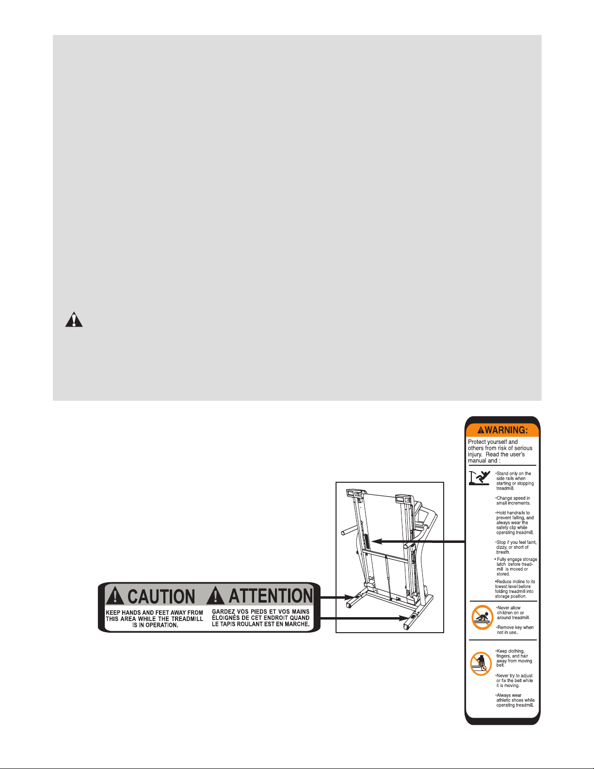
The decals shown here have been placed on the treadmill. If a decal is missing or illegible, call the toll-free telephone number on the front cover of this manual and
order a free replacement decal. Apply the decal in the location shown. Note: The
decal may not be shown at actual size.
4
BEFORE YOU BEGIN
Thank you for selecting the revolutionary NordicTrack
2300 treadmill. The C2300 treadmill offers an impres-
C
sive selection of features designed to make your workouts at home more enjoyable and effective. And when
you’re not exercising, the unique C2300 treadmill can
e folded up, requiring less than half the floor space of
b
other treadmills.
For your benefit, read this manual carefully before
using the treadmill
Book Holder
Accessory Tray
Handrail
Latch Knob
. If you have questions after read-
®
ing this manual, please see the front cover of this man-
al. To help us assist you, please note the product
u
model number and serial number before contacting us.
The model number of the treadmill is 30601.0. The serial number can be found on a decal attached to the
readmill (see the front cover of this manual for the lo-
t
cation).
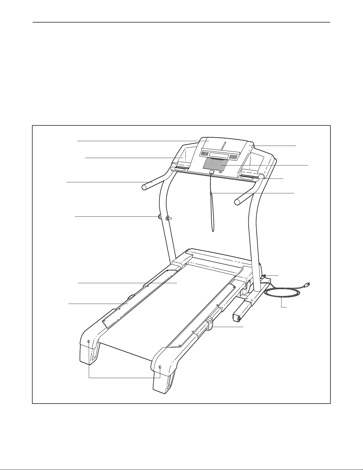
Before reading further, please familiarize yourself with
the parts that are labeled in the drawing below.
Console
Pulse Sensor
Key/Clip
Fan
Walking Belt
Foot Rail
Rear Roller
Adjustment Bolts
Reset/Off
Circuit Breaker
Power Cord
Cushioned Walking Platform
5
ASSEMBLY
Spacer Screw (60)–2
1” Tek Screw (82)–4
Console Bolt (72)–4
Extension Leg Bolt (87)–4
Star Washer (67)–8
Plastic Spacer
(101)–4
Extension Leg
Nut (106)–4
ssembly requires two persons.Set the treadmill in a cleared area and remove all packing materials. Do not
A
dispose of the packing materials until assembly is completed.
Note: The underside of the treadmill walking belt is coated with high-performance lubricant. During shipping, a
small amount of lubricant may be transferred to the top of the walking belt or the shipping carton. This is a normal
condition and does not affect treadmill performance. If there is lubricant on top of the walking belt, simply wipe off
the lubricant with a soft cloth and a mild, non-abrasive cleaner.
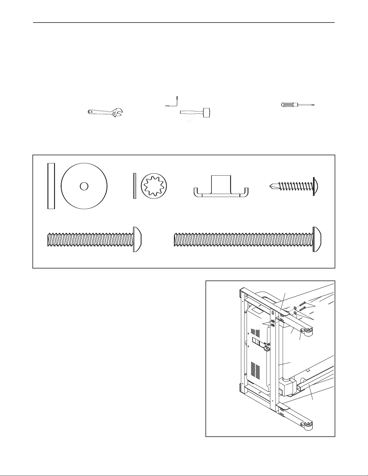
Assembly requires the included allen wrench and your own phillips screwdriver ,
adjustable wrench , and rubber mallet . For help identifying the assembly hardware, see the drawings below.
from the PART LIST on pages 34 and 35. The number following the parentheses is the quantity needed for assembly. Note: Some small parts may have been pre-assembled. If a part is not in the parts bag, check to see if
it has been pre-assembled.
The number in parentheses below each drawing is the key number of the part,
1. Make sure that the power cord is unplugged.
With the help of a second person, carefully tip the
treadmill onto its side as shown. Partially fold the Frame
(55) so the treadmill is more stable. Do not fully fold
the treadmill until it is completely assembled.
Orient an Extension Leg (97) so the Base Pad (81) is in
the position shown, and insert the Extension Leg into
the indicated bracket on the base of the Uprights (85). If
necessary, use a rubber mallet to align the holes in the
Extension Leg with the holes in the bracket.
Attach the Extension Leg (97) with two Extension Leg
Bolts (87), two Star Washers (67), and two Extension
Leg Nuts (106) as shown. Firmly tighten the
Extension Leg Bolts.
With the help of a second person, carefully tip the treadmill onto its other side. Attach the other Extension Leg
(97) as described above.
1
106
Bracket
87
67
97
81
85
55
6
2. Attach the four Base Pads (81) (only three are shown) to
the base of the Uprights (85) with four 1” Tek Screws (82)
nd four Plastic Spacers (101). Note: One replacement
a
Base Pad may be included. Use the Base Pad to replace
ny Base Pad that becomes worn.
a
With the help of a second person, carefully tip the treadmill down so the four Base Pads (81) are resting on the
floor and the Uprights (85) are in a vertical position.
2
101
55
81
101
85
01
1
2
8
81
82
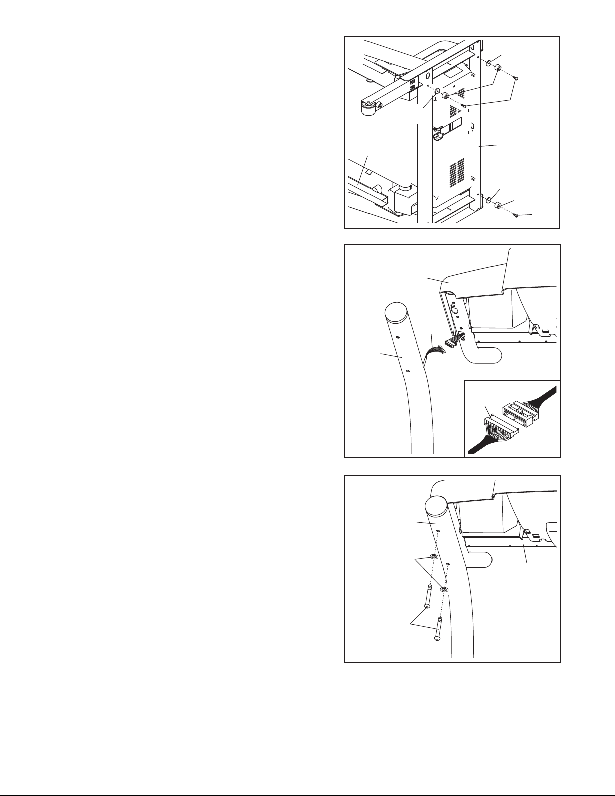
3. Remove the band securing the Upright Wire Harness (73)
to the right Upright (85). Have a second person hold the
console assembly near the right Upright.
Connect the Upright Wire Harness (73) to the wires extending from the console assembly. Make sure to con-
nect the connectors properly (see the inset drawing).
The connectors should slide together easily and
snap into place. If the connectors do not slide together
easily and snap into place, turn one connector and try
again. IF THE CONNECTORS ARE NOT CONNECTED
PROPERLY, THE CONSOLE MAY BE DAMAGED
WHEN THE POWER IS TURNED ON. Insert the connec-
tors into the right Upright (85).
4. With the help of a second person, set the console assem-
bly on the right Upright (85) and the left Upright (not
shown).
the console assembly with four Console Bolts (72) and
four Star Washers (67) (only one side is shown).
four Console Bolts before tightening any of them.
Make sure that no wires are pinched. Attach
Start all
3
Console
Assembly
73
85
73
4
85
67
72
Console
Assembly
7
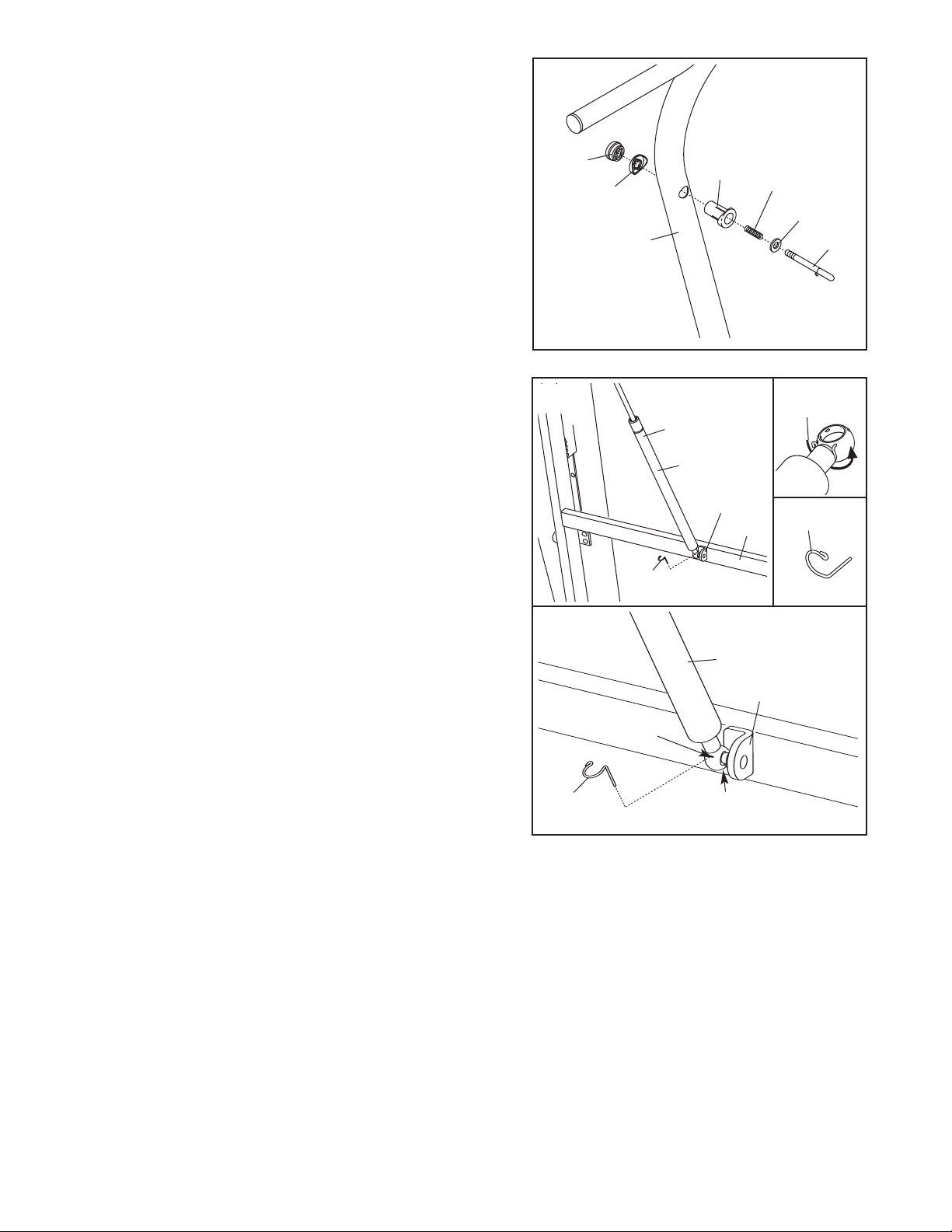
5. Remove the knob from the pin. Make sure that the collar
nd the spring are on the pin.
a
ress the Latch Insert (77) into the right side of the left
P
Upright (85), and press the Knob Insert (92) into the left
side of the left Upright. Use a rubber mallet, if necessary.
Next, insert the pin into the Latch Insert, and tighten the
knob back onto the pin.
5
nob
K
92
77
Spring
Collar
6. Place the treadmill in the storage position (see HOW TO
FOLD AND MOVE THE TREADMILL on page 27).
Hold the cylinder end of the Shock (107) near the
bracket in the center of the crossbar on the Frame (55).
See the two small inset drawings. Using your fingernail
or the end of a screwdriver, press on the end of the
Shock Pin (108) to loosen it from the Shock (107). Next,
rotate the Shock Pin and pull it out of the Shock.
careful to avoid losing the Shock Pin.
Orient the Shock (107) so it is in the position shown.
Press the end of the Shock onto the ball on the bracket.
See drawing 6a. Insert the Shock Pin (108) into the two
indicated small holes in the end of the Shock (107).
Then, rotate the Shock Pin until it clips onto the Shock.
Note: Extra Shock Pins are included.
Be
6
6a
85
108
Hole
107
Cylinder
Bracket
107
55
Bracket
Pin
108
108
108
Hole
8
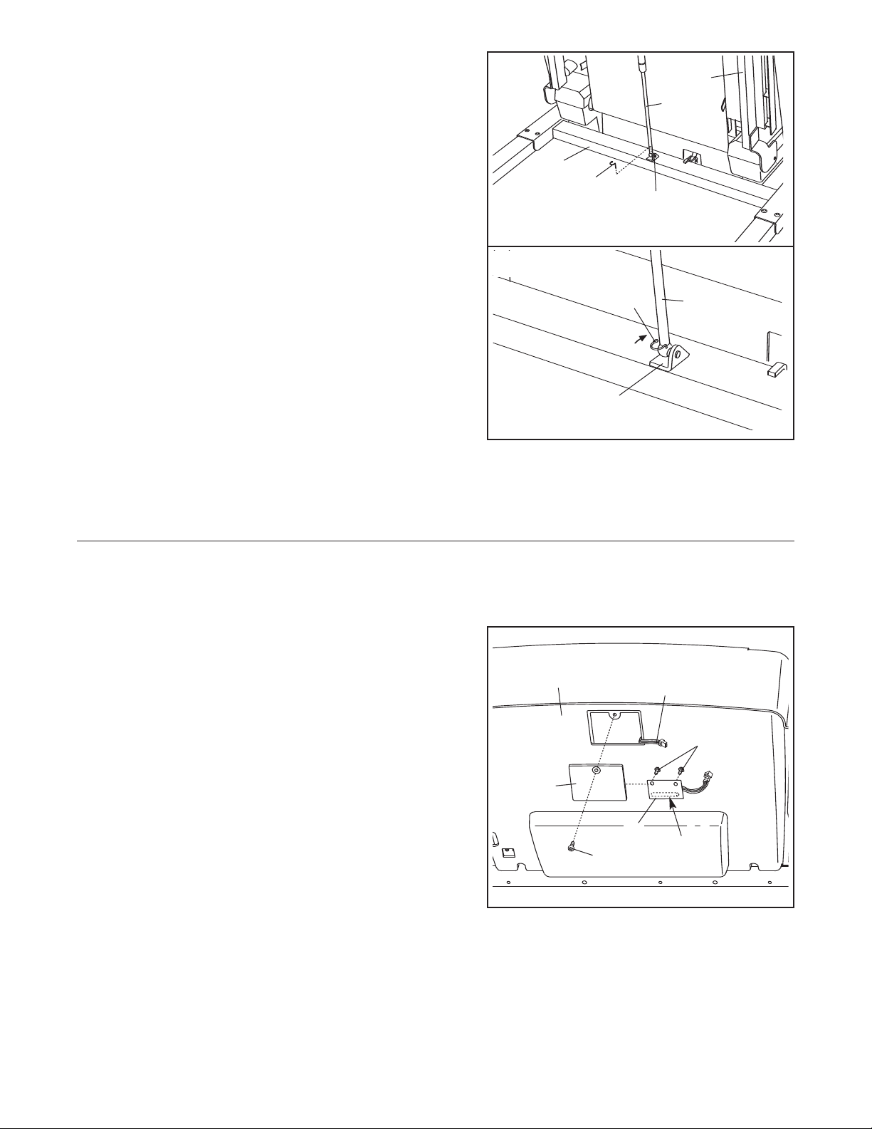
7. Remove the Shock Pin (108) from the lower end of the
Shock (107).
7
55
Plug in the power cord as described on page 10, and
urn on the power as described on page 12. Next, press
t
the Incline increase and decrease buttons until the ball
on the bracket is aligned with end of the Shock (107).
Then, press the end of the Shock onto the ball. Note: It
may be necessary to press the end of the Shock onto the
ball while the Frame (55) is moving.
See drawing 7a. Insert the end of the Shock Pin (108)
into two of the small holes in the end of the Shock (107).
Then, rotate the Shock Pin until it clips onto the Shock.
Press the Incline decrease button until the treadmill is at
the lowest incline level. Unplug the power cord. With the
help of a second person, lower the Frame (55) to the floor.
8. Make sure that all parts are properly tightened before you use the treadmill. Keep the included allen
wrench in a secure place; the allen wrench is used to adjust the walking belt (see page 30). To protect the
floor or carpet from damage, place a mat under the treadmill.
7a
85
108
108
Bracket
107
Bracket
107
If you purchase the optional chest pulse sensor (see page 26), follow the steps below to install the receiver included with the chest pulse sensor.
1. Make sure that the power cord is unplugged. Remove
the indicated Screw (7) and the Access Door (95) from
the left side of the Console Back (98).
Connect the wire on the receiver (A) to the indicated wire
2.
extending from the Console Back (98). Hold the re
ceiver so the small cylinder is oriented as shown and
is facing the Console Back. Attach the receiver to the
plastic posts on the Access Door (95) with the two included small screws.
3. Make sure that no wires are pinched. Reattach the
Access Door (95) with the Screw (7). Discard the other
wires included with the receiver.
-
98
95
7
Wire
Small
Screws
A
Small
Cylinder
9
OPERATION AND ADJUSTMENT
HE PRE-LUBRICATED WALKING BELT
T
Your treadmill features a walking belt coated with highperformance lubricant. IMPORTANT: Never apply sil-
cone spray or other substances to the walking
i
belt or the walking platform. Such substances will
deteriorate the walking belt and cause excessive
wear.
HOW TO PLUG IN THE POWER CORD
DANGER: Improper connection
of the equipment-grounding conductor can
result in an increased risk of electric shock.
Check with a qualified electrician or serviceman if you are in doubt as to whether the
product is properly grounded. Do not modify
the plug provided with the product—if it will
not fit the outlet, have a proper outlet
installed by a qualified electrician.
Your treadmill, like any other type of sophisticated
electronic equipment, can be seriously damaged by
sudden voltage changes in your home’s power.
Voltage surges, spikes, and noise interference can
result from weather conditions or from other appliances
being turned on or off. To decrease the possibility of
your treadmill being damaged, always use a surge
suppressor with your treadmill (see drawing 1 at
the right).
Use only a single-outlet surge suppressor that is
UL 1449 listed as a transient voltage surge suppressor (TVSS). The surge suppressor must have a
UL suppressed voltage rating of 400 volts or less
and a minimum surge dissipation of 450 joules.
The surge suppressor must be electrically rated for
120 volts AC and 15 amps. There must be a monitoring light on the surge suppressor to indicate
whether it is functioning properly. Failure to use a
properly functioning surge suppressor could result
in damage to the control system of the treadmill. If
the control system is damaged, the walking belt
may change speed, accelerate, or stop unexpectedly, which may result in a fall and serious injury.
This product must be grounded. If it should malfunc-
tion or break down, grounding provides a path of least
resistance for electric current to reduce the risk of electric shock. This product is equipped with a cord having
an equipment-grounding conductor and a grounding
lug.
p
and plug the surge suppressor into an appropriate
outlet that is properly installed and grounded in
accordance with all local codes and ordinances.
I
GFCI-equipped outlets.
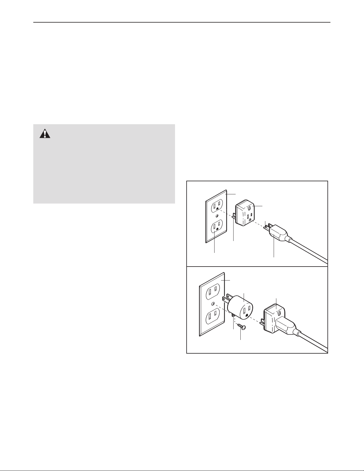
This product is for use on a nominal 120-volt circuit,
and has a grounding plug that looks like the plug illustrated in drawing 1 below. A temporary adapter that
looks like the adapter illustrated in drawing 2 may be
used to connect the surge suppressor to a 2-pole
receptacle as shown in drawing 2 if a properly
grounded outlet is not available.
The temporary adapter should be used only until a
properly grounded outlet (drawing 1) can be installed
by a qualified electrician.
The green-colored rigid ear, lug, or the like extending
from the adapter must be connected to a permanent
ground such as a properly grounded outlet box cover.
Whenever the adapter is used it must be held in place
by a metal screw.
covers are not grounded. Contact a qualified electrician to determine if the outlet box cover is
grounded before using an adapter.
lug the power cord into a surge suppressor,
P
mportant: The treadmill is not compatible with
1
Grounded Outlet Box
Surge Suppressor
Grounding Pin
Grounding Pin
Grounded Outlet
2
Grounded Outlet Box
Adapter
Lug
Metal Screw
Some 2-pole receptacle outlet box
Grounding Plug
Surge Suppressor
10
Key
Clip
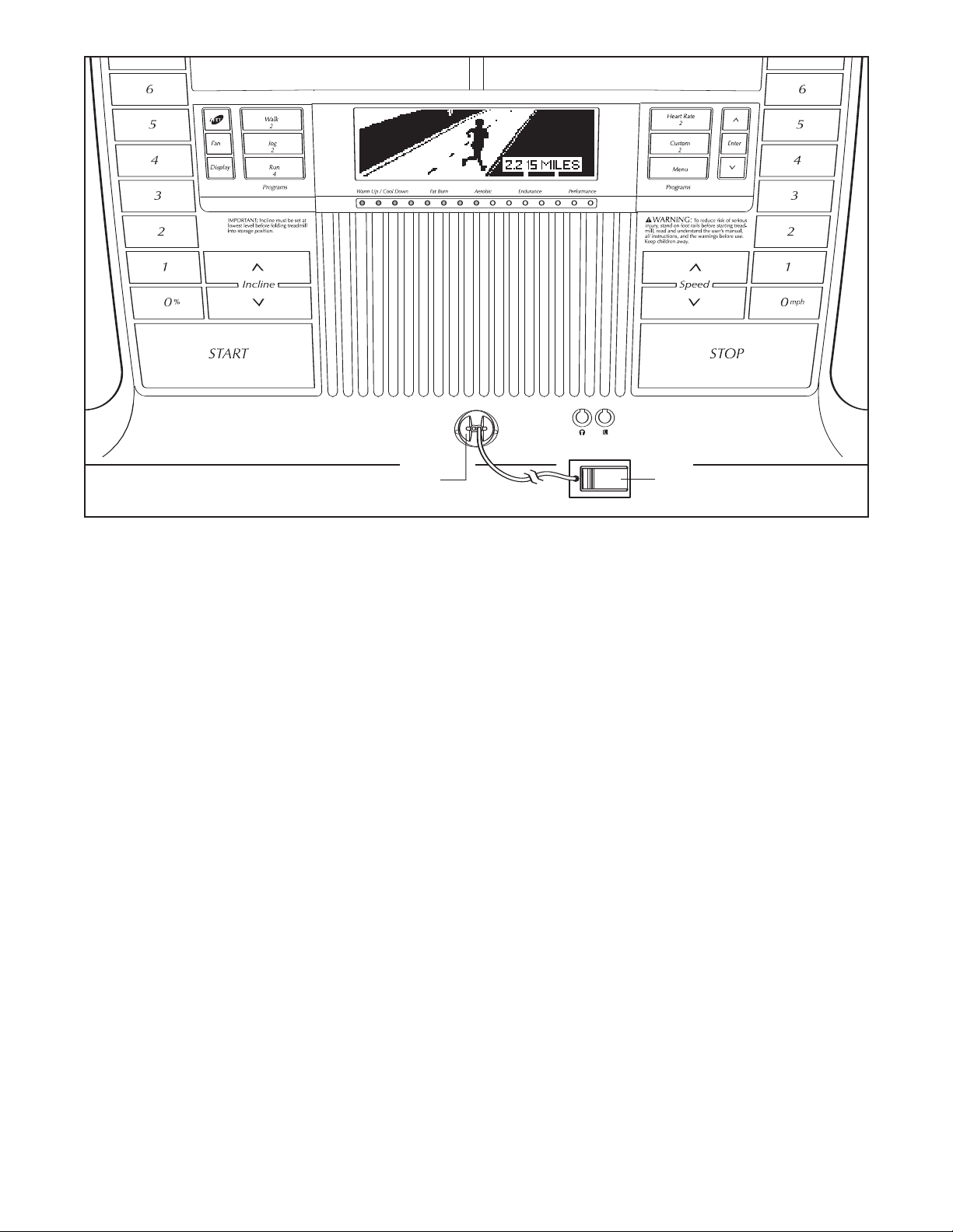
FEATURES OF THE CONSOLE
The treadmill console offers an impressive array of
features designed to make your workouts more effective and enjoyable. When the manual mode of the console is selected, the speed and incline of the treadmill
can be changed with the touch of a button. As you exercise, the console will display continuous exercise
feedback. You can even measure your heart rate using
the handgrip pulse sensor or the optional chest pulse
sensor (see page 26).
In addition, the console features eight preset programs—two Walk programs, two Jog programs, and
four Run programs. Each program automatically controls the speed and incline of the treadmill as it guides
you through an effective workout. You can even create
Custom programs and save them for future use. The
console also offers two Heart Rate programs that control the speed and incline of the treadmill to help you
keep your heart rate near target heart rate settings.
Note: The Heart Rate programs require the use of the
optional chest pulse sensor.
The console also features iFIT interactive technology.
Having iFIT technology is like having a personal trainer
in your home. Using a stereo audio cable, you can connect the treadmill to your portable stereo, home stereo,
computer, or VCR and play special iFIT MP3, CD, and
video programs (iFIT MP3 programs, CDs, and video-
cassettes are available separately). iFIT programs automatically control the speed and incline of the treadmill
as a personal trainer guides you through every step of
your workout; high-energy music provides added motivation.
grams, go to www.iFIT.com. To purchase iFIT CDs
or videocassettes, call the toll-free telephone number on the front cover of this manual.
With the treadmill connected to your computer, you
can also go to www.iFIT.com and access iFIT programs directly from our Web site. See www.iFIT.com
for more information.
To turn on the power, follow the steps on page 12. To
use the main menu of the console,
use the manual mode, see page 13. To use a preset
program, see page 16. To create and use a Custom
program, see pages 17 and 18. To use a Heart Rate
program, see page 19. To use an iFIT MP3, CD, or
video program, see page 23. To use an iFIT program
directly from our Web site, see page 25.
Note: If there is a sheet of clear plastic on the face of
the console, peel off the plastic.
the walking platform, wear clean athletic shoes while
using the treadmill. The first time the treadmill is used,
observe the alignment of the walking belt, and center
the walking belt if necessary (see page 30).
To purchase and download iFIT MP3 pro-
see page 12. To
To prevent damage to
1
1
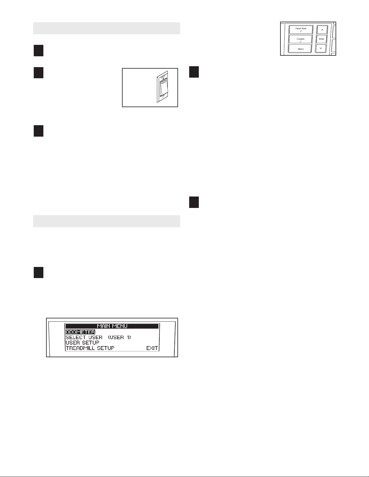
OW TO TURN ON THE POWER
H
Plug in the power cord (see page 10).
1
To highlight options
within the main menu,
ress the up and down
p
arrow buttons beside
he Menu button.
t
Locate the reset/off cir-
2
cuit breaker on the
readmill frame near
t
the power cord. Make
sure that the circuit
breaker is in the reset
position.
Stand on the foot rails of the treadmill. Find the
3
clip attached to the key (see the drawing on page
11) and attach the clip securely to the waistband
of your clothes. Next, insert the key into the console. After a moment, the display will light.
Important: In an emergency situation, the key
can be pulled from the console, causing the
walking belt to slow to a stop. Test the clip by
carefully taking a few steps backward; if the
key is not pulled from the console, adjust the
position of the clip.
HOW TO USE THE MAIN MENU
The console’s main menu allows you to view information and to enter settings before you begin exercising.
Follow the steps below to use the main menu.
Press the Menu button.
Reset
Position
1
When the Menu button is pressed, the main menu
will appear in the display. The main menu includes four options: ODOMETER, SELECT
USER, USER SETUP, and TREADMILL SETUP.
View the Odometer.
2
Highlight the word ODOMETER in the main menu
and then press the Enter button.
When the Enter button is pressed, the display will
show the total number of miles run by User 1 and
User 2 since the treadmill was purchased. The
display will also show the trip distance—the distance run during a recent period of time, such as
the most recent month—for User 1 and User 2. To
reset the trip distance, first highlight USER 1 or
USER 2 and press the Enter button. Then, highlight NO or YES and press the Enter button.
To reselect the main menu, highlight EXIT and
then press the Enter button.
Designate yourself as User 1 or User 2.
3
The console can keep track of information and
save settings for two different users. Highlight the
words SELECT USER in the main menu and then
press the Enter button.
To identify yourself as User 1 or User 2, highlight
USER 1 or USER 2 and then press the Enter button.
The console can automatically prompt you to
identify yourself as User 1 or User 2 each time
you insert the key into the console. Highlight the
words SELECT USER in the main menu and then
press the Enter button. Next, highlight USER DISPLAY OPTIONS and press the Enter button. Next,
highlight PROMPT FOR USER and press the
Enter button. Then, highlight NO or YES and
press the Enter button.
To view the odometer, see step 2. To designate
yourself as User 1 or User 2, see step 3. To
enter user information, see step 4. To change
console settings,
see step 5.
The console can also display a welcome message
each time you insert the key into the console.
Highlight SHOW USER WELCOME and press the
Enter button. Then, highlight NO or YES and
press the Enter button.
To reselect the main menu, press the Menu button
twice.
12
 Loading...