


 Loading...
Configuring, Installing, and
Using Carrier Infrastructure
Broadband Wireless Access System
Part Number:104-0100-0011
i

BaseConnect, Expedience, NetProvision, and ProvisionLink are trademarks of NextNet Wireless, Inc.
©2000-2003 NextNet Wireless, Inc. All rights reserved.
WARNING: This equipment has been tested with a 19 dBi gain antenna and found to comply with the FCC guidelines for Radio Frequency Radiation Exposure Limits as detailed below. A minimum of 2 meters or 6.5 feet of separation between the antenna and all persons must be maintained.
Radio Frequency Radiation Exposure Limits.
TABLE 1. Limits for Maximum Permissible Exposure (MPE)
Frequency range |
Electric field- |
Magnetic field- |
Power density |
Averaging time |
(MHz) |
strength (V/m) |
strength (A/m) |
(mW/cm 2) |
(minutes) |
|
(A) Limits for Occupational/Controlled Exposures |
|
||
0.3-3.0 |
614 |
1.63 |
*(100) |
6 |
3.0-30 |
1842/f |
4.89/f |
*(900/f2) |
6 |
30-300 |
61.4 |
0.163 |
1.0 |
6 |
300-1500 |
— |
— |
f/300 |
6 |
1500-100,000 |
— |
— |
5 |
6 |
|
(B) Limits for General Population/Uncontrolled Exposure |
|
||
0.3-1.34 |
614 |
1.63 |
*(100) |
30 |
1.34-30 |
824/f |
2.19/f |
*(180/f2) |
30 |
30-300 |
27.5 |
0.073 |
.2 |
30 |
300-1500 |
— |
— |
f/1500 |
30 |
1500-100,000 |
— |
— |
1.0 |
30 |
f = frequency in MHz
* = Plane-wave equivalent power density
NOTE 1 TO TABLE 1: Occupational/controlled limits apply in situations in which persons are exposed as a consequence of their employment provided those persons are fully aware of the potential for exposure and can exercise control over their exposure.
Limits for occupational/controlled exposure also apply in situations when an individual is transient through a location where occupational/controlled limits apply provided he or she is made aware of the potential for exposure.
NOTE 2 TO TABLE 1: General population/uncontrolled exposures apply in situations in which the general public may be exposed, or in which persons that are exposed as a consequence of their employment may not be fully aware of the potential for exposure or can not exercise control over their exposure.
Note: This equipment has been tested and found to comply with the limits for a Class A digital device, pursuant to part 15 of the FCC rules. These limits are designed to provide reasonable protection against harmful interference when the equipment is operated in a commercial environment. This equipment generates, uses, and can radiate radio-frequency energy, and, if not installed and used in accordance with the installation manual, may cause harmful interference to radio communications. Operation of this equipment in a residential area is likely to cause harmful interference, in which case users will be required to correct the interference at their own expense.
ii

TABLE 2. Technical Information
Transmitting power |
1m watts to 2 watts |
|
1m watts to 5 watts (high power option) |
Operating voltage |
120 VAC nominal |
Frequency band |
2500 - 2686 MHz TX/RX |
Frequency stability |
±1.0 ppm |
Number of channels |
31 |
Channel bandwidth |
6 MHz |
Modulation |
Orthogonal frequency division multiplex |
Transmission |
Time division duplex/time division multiplex |
NextNet Wireless, Inc. recommends the following antennas for base station installations:
TABLE 3. Recommended antennas for base station installations
Manufacturer |
Antenna type |
Model/part number |
|
Stella Doradus |
120 degree vertical |
26 |
12005V |
|
polarization |
|
|
|
18 dBi gain |
|
|
Stella Doradus |
90 degree vertical |
26 |
9005V |
|
polarization |
|
|
|
19 dBi gain |
|
|
Stella Doradus |
90 degree vertical |
26 |
9007.5NV |
|
polarization |
|
|
|
17 dBi gain |
|
|
Stella Doradus |
90 degree horizontal |
26 |
9005H |
|
polarization |
|
|
|
19 dBi gain |
|
|
Til-Tek |
Omni vertical polar- |
TA-2550 |
|
|
ization |
|
|
10 dBi gain
This Class A digital apparatus complies with Canadian ICES-003.
THE SPECIFICATIONS AND INFORMATION REGARDING THE PRODUCTS IN THIS MANUAL ARE SUBJECT TO CHANGE WITHOUT NOTICE. ALL STATEMENTS, INFORMATION, AND RECOMMENDATIONS IN THIS MANUAL ARE BELIEVED TO BE ACCURATE BUT ARE PRESENTED WITHOUT WARRENTY OF ANY KIND. USERS MUST TAKE FULL RESPONSIBILITY FOR THEIR APPLICATION OF ANY PRODUCT.
NOTWITHSTANDING ANY OTHER WARRANTY HEREIN, ALL DOCUMENT FILES AND SOFTWARE ARE PROVIDED “AS IS” WITH ALL FAULTS. NEXTNET WIRELESS DISCLAIMS ALL WARRANTIES, EXPRESSED OR IMPLIED, INCLUDING, WITHOUT LIMITATION, THOSE OF MERCHANTABILITY, FITNESS FOR A PARTICULAR PURPOSE AND NONINFRINGEMENT OR ARISING FOM A COUSRE OF DEALING, USAGE, OR TRADE PRACTICE.
IN NO EVENT SHALL NEXTNET WIRELESS OR ITS SUPPLIERS BE LIABLE FOR ANY INDIRECT, SPECIAL, CONSEQUENTIAL, OR INCIDENTAL DAMAGES, INCLUDING, WITHOUT LIMITATION, LOST PROFITS OR LOSS OF DAMAGE TO DATA ARISING OUT OF THE USE OR INABILITY TO USE THIS MANUAL, EVEN IF NEXTNET WIRELESS HAS BEEN ADVISED OF THE POSSIBILITY OF SUCH DAMAGES.
iii

iv
CONTENTS
Preface About this guide
Preface overview .............................................................................. |
xiii |
About this guide .............................................................................. |
xiii |
Chapters in this guide ........................................................................................ |
xiv |
Additional documentation ............................................................... |
xiv |
Typographical conventions this guide uses ...................................... |
xv |
Where to go for more help ............................................................... |
xvi |
Technical support............................................................................................... |
xvi |
Documentation additions and corrections..................................................... |
xvi |
Introduction to backhaul installations
Chapter overview .............................................................................. |
1-1 |
System overview ................................................................................ |
1-1 |
System overview ................................................................................................ |
1-1 |
Infrastructure overview .................................................................................... |
1-2 |
Installation overview ......................................................................... |
1-3 |
Planning the installation .................................................................. |
1-4 |
Choosing an installation location .................................................................... |
1-5 |
Assessing network access provider equipment needs ................................. |
1-6 |
Planning for the antennas and antenna installation tips .............................. |
1-6 |
Designing the deployment of base stations .................................................. |
1-7 |
Configuring network architecture
Chapter overview ............................................................................. |
2-9 |
Architecture overview ...................................................................... |
2-9 |
Configuring switches ...................................................................... |
2-10 |
Configuring the switch at the cell site .......................................................... |
2-10 |
Configuring the head end switch .................................................................. |
2-10 |
Configuring the ISP switch ............................................................................ |
2-10 |
Selecting links and circuits ............................................................. |
2-10 |
Selecting links based on maximum rate needed ......................................... |
2-10 |
Selecting links based on another rate ........................................................... |
2-11 |
Configuring the AP server
Chapter overview ............................................................................ |
3-13 |
AP server overview .......................................................................... |
3-13 |
Starting the AP server ..................................................................... |
3-13 |
v
Configuring the AP server .............................................................. |
3-14 |
Defining AP server users and administrators ............................................. |
3-14 |
Defining zone names ...................................................................................... |
3-19 |
Defining ISPs ................................................................................................... |
3-20 |
Changing ISP information ............................................................................. |
3-22 |
Monitoring ISPs and base stations ............................................................... |
3-23 |
Configuring a standby AP server
Chapter overview ............................................................................ |
4-25 |
Standby AP server overview ............................................................ |
4-25 |
Configuring the base station with standby AP server information 4-25
Setting up common configuration file and directory ................................. |
4-26 |
Switching from the primary AP server to the secondary AP server ....... |
4-28 |
Configuring base stations
Chapter overview ............................................................................ |
5-33 |
Before you begin ............................................................................. |
5-33 |
Setting up connection methods used to configure base stations ..5-34
Setting up terminal emulation access ........................................................... |
5-34 |
Setting up Telnet access ................................................................................. |
5-34 |
Setting up web access ..................................................................................... |
5-36 |
Setting up SNMP access ................................................................................ |
5-37 |
Setting base station configuration parameters ............................... |
5-39 |
set airlink channel ........................................................................................... |
5-39 |
set airlink downlink power ............................................................................. |
5-40 |
set airlink downlink bias ................................................................................ |
5-42 |
set system location .......................................................................................... |
5-43 |
set system name ............................................................................................... |
5-44 |
set airlink state ................................................................................................. |
5-44 |
Recommended parameter changes ................................................ |
5-44 |
set system cell .................................................................................................. |
5-44 |
set system sector .............................................................................................. |
5-44 |
set DHCP state ................................................................................................ |
5-44 |
Setting legacy and management VLAN IDs ............................................... |
5-45 |
Setting up Syslog ............................................................................ |
5-45 |
Configuring the authority that grants network access to CPEs ....5-46
Using base station caching feature for re-registering CPEs ..................... |
5-46 |
Remote authority: setting up the provisioning server to grant |
|
CPEs network access ...................................................................................... |
5-47 |
Local authority: setting up the base station to grant CPEs |
|
network access ................................................................................................. |
5-48 |
Configuring the time signal used by base stations ........................ |
5-48 |
Configuring the GPS to supply the time signal .......................................... |
5-48 |
Configuring a base station to supply a time signal ..................................... |
5-49 |
vi C o n f i g u r i n g , I n s t a l l i n g , a n d U s i n g C a r r i e r I n f r a s t r u c t u r e
Installing base stations
Chapter overview ............................................................................ |
6-51 |
Before you begin ............................................................................. |
6-51 |
Cell wiring ....................................................................................... |
6-52 |
Base station connectors .................................................................. |
6-53 |
Ethernet (data) and power connector .......................................................... |
6-54 |
TVS module connectors ................................................................................ |
6-56 |
GPS connectors ............................................................................................... |
6-57 |
Serial interface connector ............................................................................... |
6-58 |
Antenna connector ......................................................................................... |
6-58 |
Mounting the base station .............................................................. |
6-59 |
Mounting the base station to a wall .............................................................. |
6-59 |
Mounting the base station to a tower .......................................................... |
6-60 |
Mounting the base station to a 19 inch rack ............................................... |
6-60 |
Connecting the antenna to the base station ................................... |
6-60 |
Antenna connection tips ................................................................................ |
6-60 |
Connecting the antenna to the base station ................................................ |
6-60 |
Connecting the GPS equipment to a base station ......................... |
6-61 |
GPS equipment mounting tips ..................................................................... |
6-61 |
Connecting the GPS unit to the base station ............................................. |
6-61 |
Connecting to the backbone network ............................................ |
6-62 |
Powering base stations ................................................................... |
6-62 |
Powering tips ................................................................................................... |
6-62 |
Powering the base station .............................................................................. |
6-63 |
Testing and managing the network
Chapter overview ............................................................................ |
7-65 |
Testing the setup overview ............................................................. |
7-65 |
Installing the ISP’s provisioning server ....................................................... |
7-65 |
Testing the connection between the AP server and the |
|
provisioning server .......................................................................................... |
7-66 |
Ensuring CPE access to ISP VLAN ............................................................ |
7-66 |
Network management overview ..................................................... |
7-66 |
Fault isolation overview ................................................................................. |
7-67 |
Performance management overview ............................................................ |
7-68 |
Configuration management overview .......................................................... |
7-68 |
Accounting feature overview ........................................................................ |
7-68 |
Parts list
Appendix overview ........................................................................ |
A-69 |
v i i
Supported frequency ranges
Appendix overview ........................................................................ |
B-71 |
MMDS frequency range ................................................................................ |
B-71 |
3.3 frequency range ........................................................................................ |
B-73 |
3.5 frequency range ........................................................................................ |
B-73 |
GPS status codes
Appendix overview ........................................................................ |
C-75 |
viii C o n f i g u r i n g , I n s t a l l i n g , a n d U s i n g C a r r i e r I n f r a s t r u c t u r e
FIGURES
About this guide
Introduction to backhaul installations
Base station ....................................................................................................... |
1-2 |
Configuring network architecture |
|
Configuring the AP server |
|
AP server log in page ...................................................................................... |
3-14 |
Access Provider Management page .............................................................. |
3-15 |
Configure page ................................................................................................ |
3-16 |
Administrators page ........................................................................................ |
3-17 |
New User page ................................................................................................ |
3-18 |
Base Station Attributes page .......................................................................... |
3-19 |
ISP Management page .................................................................................... |
3-20 |
Create new ISP page ....................................................................................... |
3-21 |
ISP details page ................................................................................................ |
3-22 |
Monitor ISPsBase Stations page ................................................................ |
3-23 |
Base Station Properties page ......................................................................... |
3-24 |
Configuring a standby AP server |
|
Configuration files to share between primary and secondary AP |
|
servers ............................................................................................................... |
4-26 |
Configuring base stations |
|
Installing base stations |
|
Cell wiring diagram ......................................................................................... |
6-52 |
Base station connectors .................................................................................. |
6-53 |
Ethernet (data) and power connector .......................................................... |
6-54 |
Ethernet (data) and power connector .......................................................... |
6-54 |
TVS module connector: Base station connector ........................................ |
6-56 |
TVS module connector: power/Ethernet connector ................................ |
6-57 |
GPS connector ................................................................................................ |
6-57 |
Serial interface connector ............................................................................... |
6-58 |
Base station mounting template .................................................................... |
6-59 |
Testing and managing the network
Parts list
Supported frequency ranges
GPS status codes
ix

x C o n f i g u r i n g , I n s t a l l i n g , a n d U s i n g C a r r i e r I n f r a s t r u c t u r e
TABLES
About this guide
Chapters and appendices in the guide ............................................................. |
xiv |
Additional documentation ................................................................................ |
xiv |
Typographical conventions ............................................................................... |
xv |
Contacting technical support ........................................................................... |
xvi |
Introduction to backhaul installations
Advantages/disadvantages of location choices ............................................ |
1-5 |
Configuring network architecture |
|
Configuring the AP server |
|
Create new ISP page ....................................................................................... |
3-21 |
Configuring a standby AP server |
|
Configuring base stations |
|
Transmit power levels ..................................................................................... |
5-40 |
Transmit power levels ..................................................................................... |
5-40 |
Downlink rate based on modulation method ............................................. |
5-42 |
Uplink data rate for 4-QAM modulation method ..................................... |
5-42 |
Uplink data rate for 16-QAM modulation method ................................... |
5-42 |
Uplink data rate for 64-QAM modulation method ................................... |
5-43 |
Uplink data rate for 16-QAM lite modulation method ............................. |
5-43 |
Methods used to grant CPEs access to ISPs’ VLANs .............................. |
5-46 |
Installing base stations |
|
Ethernet/power base station cable choices ................................................ |
6-55 |
Ethernet/power cable pins ............................................................................ |
6-55 |
Function of wires in cable 597-6027-0xxx .................................................. |
6-55 |
Testing and managing the network |
|
Parts list |
|
Parts list ........................................................................................................... |
A-69 |
Supported frequency ranges |
|
GPS status codes |
|
GPS status codes and meaning .................................................................... |
C-75 |
xi

xii C o n f i g u r i n g , I n s t a l l i n g , a n d U s i n g C a r r i e r I n f r a s t r u c t u r e

P R E F A C E
ABOUT THIS GUIDE
Preface overview
Thank you for choosing the Expedience™ system from NextNet Wireless. This guide describes how to configure and install the system’s base transceiver station (BTS).
This preface describes:
•Audience for this guide
•Additional documentation
•Typographical conventions used in this guide
•Where to go for more help
About this guide
This guide describes how to configure and install the system’s base station. It also describes how to configure and work with the access provider (AP) server.
This guide is intended for network and system administrators who must install, configure, and manage base stations and the AP server. This guide provides detailed configuration and installation instructions.
It is assumed readers of this guide are familiar with:
•Basic networking concepts
•Layer 2 (link layer) of OSI model
•Cell structure engineering
xiii

Chapters in this guide
Table i describes the chapters and appendices in this guide.
Table i |
Chapters and appendices in the guide |
|
|
|
|
Chapter |
|
Description |
|
|
|
Preface |
|
Provides an overview of the guide, related documentation, |
|
|
the guide’s intended audience, typographical conventions, |
|
|
and methods for obtaining technical support. |
Chapter 1 Introduction to |
Provides an overview of the Expedience system and of the |
|
backhaul installations |
system’s base station component. It provides an installation |
|
|
|
overview and describes things you need to consider before |
|
|
installing base stations. |
Chapter 2 Configuring base |
Describes how to configure base stations, including how to |
|
stations |
|
use Telnet or Term to set up a base station before deploying |
|
|
it and mounting it to a tower or building. The chapter also |
|
|
describes how to configure base stations after you have |
|
|
deployed them, for example, to maintain the system and |
|
|
optimize system performance. |
Chapter 3 Installing base |
Explains how to install a base station at a cell site. Also |
|
stations |
|
describes the components used to mount the base station on |
|
|
a building or tower. |
Chapter 4 Testing the |
Explains how to work with the ISP to ensure the network is |
|
network setup |
installed and running correctly. |
|
Appendix A Parts list |
Lists part numbers of system components that are related to |
|
|
|
base station installations |
Appendix B Supported |
Provides reference information about the frequency ranges |
|
frequency ranges |
in which the equipment can operate. |
|
Additional documentation
If you cannot find the information you need in this guide, you may want to refer to the documents described in Table ii.
Table ii |
Additional documentation |
|
|
|
|
Guide |
|
Description |
|
|
|
Getting Started with the |
Provides an overview of the Expedience system, its |
|
Expedience System |
components, its network architecture, and options for |
|
|
|
selecting a deployment scheme for the system in the service |
|
|
provider (backbone) network. |
Configuring, Installing, and |
This is the guide you are currently reading. Describes how to |
|
Using Carrier Infrastructure |
set up and configure base stations, including how to connect |
|
|
|
antenna systems, the backbone network equipment, and |
|
|
global positioning system (GPS) equipment. |
|
|
Also provides an overview of the AP server and how to |
|
|
configure the AP server for your network. |
Using the NextNet |
Describes the NextNet operating system (NNOS), which is |
|
Operating System (NNOS) |
the common operating system for the system’s base station |
|
|
|
devices and customer premise equipment (CPE) devices. |
|
|
This guide describes how you can configure the operating |
|
|
system on devices by using commands issued from Telnet, |
|
|
Terminal, or a Web interface. |
xiv C o n f i g u r i n g , I n s t a l l i n g , a n d U s i n g C a r r i e r I n f r a s t r u c t u r e

Table ii |
Additional documentation |
|
|
|
|
Guide |
|
Description |
|
|
|
Configuring and monitoring |
Intended for use by an ISP. Provides an overview of the |
|
the ISP network |
Expedience system, its components, and its network |
|
|
|
architecture. This guide describes how to install and |
|
|
configure the ISP’s provisioning server. It describes how to |
|
|
define service level agreements (SLAs) and how SLAs are |
|
|
enforced by the NetEnforcer device. |
Expedience Broadband |
Intended for use by your subscribers, this guide describes |
|
Wireless Access Modem |
how to install a RSU (that is, an indoor CPE) at a subscriber |
|
|
|
site. Your subscribers can completely install the RSU. |
|
|
The guide explains, in detail, how to connect the RSU to a |
|
|
computer or to a network device. It explains system pre- |
|
|
requisites, and provides troubleshooting information. |
|
|
This guide is available in electronic (pdf) format, on the |
|
|
CD-ROM that accompanies the LinkMonitor software. |
Installing the RSU |
Intended for use by your subscribers, this guide describes |
|
|
|
how to quickly install a RSU directly to a computer. |
Expedience NLOS |
Intended for use by a professional installer, this guide |
|
Outdoor Broadband |
describes how to install an outdoor CPE. |
|
Wireless Access Modem |
|
|
Typographical conventions this guide uses
Table iii describes the typographical conventions that this guide uses.
Table iii Typographical conventions
Convention |
Meaning |
|
|
Bold face |
If you are using a graphical user interface (GUI), bold face |
|
indicates a button, menu option, icon, and so on, that you |
|
manipulate directly. |
|
If you are using a command line interface, bold face indicates |
|
commands and keywords. |
|
Bold face can also indicate information that you must enter. |
|
|
Italic face |
Arguments for which you supply values are in italic face. |
Courier |
A command you type in, exactly as it appears, at a command |
(mono-spaced) font |
line. |
[ ... ] |
Arguments that appear inside square brackets [ ], are |
|
optional. |
|
Also, when the guide shows a system prompt, the default |
|
system prompt appears inside square brackets. |
{..} | {..} |
Required keywords are grouped in braces and separated by |
|
vertical bars. |
Note |
Notes contain helpful suggestions for the reader. |
|
|
<...> |
Non-printing characters, such as passwords, appear in angle |
|
brackets. |
Caution |
Cautions contain information about which the reader must |
|
exercise care. |
Warning |
Warnings contain information about how readers might do |
|
something resulting in harm to themselves or in damage to |
|
equipment or data. |
xv

Where to go for more help
This section describes how to obtain support for your NextNet Wireless product. It also describes how to provide comments on the product documentation.
Technical support
NextNet Wireless is committed to providing our customers with high quality technical support. Table iv describes how to contact technical support.
Table iv Contacting technical support
Contact |
Description |
|
|
Phone |
1.877.962.2200 |
support@nextnetwireless.com |
|
|
|
Web site |
www.nextnetwireless.com |
Documentation additions and corrections
If you find documentation errors, or want to see additional information not presented in this guide, please contact our documentation group at the following e-mail address:
techdocs@nextnetwireless.com
xvi C o n f i g u r i n g , I n s t a l l i n g , a n d U s i n g C a r r i e r I n f r a s t r u c t u r e

C H A P1T E R
INTRODUCTION TO BACKHAUL
INSTALLATIONS
Chapter overview
This chapter provides an overview of the Expedience system and of the system’s infrastructure components: the base transceiver station (BTS), the access provider (AP) server, and the network switches. The chapter provides an installation overview. It also describes things you need to consider before installing base stations.
System overview
This section provides a brief overview of the Expedience system, as well as the infrastructure that network access providers must install. For additional system overview information, refer to the guide “Getting Started with the Expedience System.”
System overview
NextNet Wireless designed the Expedience system to give small office, home office (SOHO), and residential subscribers high speed, wireless access to network communication systems, such as the Internet. The Expedience system is an end-to-end broadband wireless access system and operates in several frequency ranges.
The system was designed to allow network access providers to re-sell network bandwidth to ISPs on a wholesale basis. In turn, the ISPs sell access to their subscribers on a retail basis. To support multiple ISPs on the network, the system uses virtual LAN (VLAN) technology.
The system does not have a line-of-sight (LOS) requirement between the base station and the CPEs. The air link between base stations and CPEs functions as an Ethernet bridge carrying IP/ARP packets. Time division duplex (TDD) and cellular deployment offer you flexibility in adjusting downlink versus uplink airtime.
1-1
Infrastructure overview
The base station and AP server are network infrastructure components supplied by NextNet Wireless. The network access provider configures and maintains this equipment.
Additional infrastructure components include switches for use at the base station cell sites, and the head-end switch. These switches are supplied by the network access provider. If desired, the network access provider can purchase the switches through NextNet Wireless.
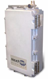
Base station overview
The base station maintains contact with CPEs at your subscribers’ sites. The base station integrates the transceiver and modem into one device.
Under typical configurations, the base station covers an approximate radius of 2 to 3 miles, with a 5 mile maximum. If desired, network access providers can configure their base stations to cover a maximum radius of 20 miles. To cover up to 20 miles, the network access provider enables the extended range feature.
The base stations are provided by NextNet Wireless. Figure 1.1 shows a base station.
Figure 1.1 Base station
AP server overview
The AP server acts as a relay for the CPE registration events which arrive from base stations (on the management VLAN) and are forwarded to the correct ISP provisioning server (over the control VLAN).
The base stations each have a TCP/IP connection to the AP server. The base stations use their connection to forward CPE registration requests to the AP server.
The AP server is provided by NextNet Wireless.
1-2 C o n f i g u r i n g , I n s t a l l i n g , a n d U s i n g C a r r i e r I n f r a s t r u c t u r e

Head-end switch, base station cell switch, and ISP switch overview
The network access provider must supply switches for their network, which include the headend switch and the switches used at the base station cell site. The network access provider must also assist their ISPs when the ISPs program their switches with the proper ISP VLAN IDs.
The base stations are grouped together into cells, with between 1 and 6 base stations at a cell site. (If the network access provider chooses to stack base stations, more than 6 base stations can exist in a cell.) To form the base station LAN, the base stations are connected to a switch at the cell site.
WAN links are then used to connect the cell sites to the head end switch. The head end switch splits incoming traffic to the management VLAN and to the appropriate ISP VLAN. The ISP then has a configured switch that controls traffic coming into and out of the ISP VLANs.
Installation overview
This section provides a high-level overview of the base station installation process. Other sections in this guide then explain these installation tasks in detail.
The tasks you perform to deploy base stations are:
1Plan the installation of base stations:
a Choose an appropriate location for the base station installation. For more information, refer to the section “Choosing an installation location” on page 1-5 in this chapter.
b Design the deployment of base stations. Determine how base stations will be deployed by marking a location on a map that shows where each base station will be installed. Also determine naming conventions for cells, sectors, zones, and base stations names. For more information, refer to the section, “Designing the deployment of base stations” on page 1-7.
2Plan for system components that you need to supply to complete the network. For more information, refer to the section “Assessing network access provider equipment needs” on page 1-6 in this chapter.
3Install and configure the access provider (AP) server. For more information, refer to Chapter 3, “Installing the AP server,” in this guide.
4On the AP server, configure zone names, VLAN IDs, and the ISP IDs. For more information, refer to Chapter 3, “Installing the AP server,” in this guide.
5Using the NextNet Operating System (NNOS) configure the base stations before deploying them in the field. For more information, refer to the chapter “Configuring base stations” in this guide.
6Mount the base station at the site you selected. For more information, refer to the section “Mounting the base station” on page 6-59 in this guide.
7Connect the antenna to the base station, as described in the section “Connecting the antenna to the base station” on page 6-60.
8Mount the GPS device and connect it to the base station. One GPS device can service the multiple base stations at a cell site. For more information, refer to the section “Connecting the GPS equipment to a base station” on page 6-61 in this guide.
1-3

9Connect the base station to the transcient voltage suppressor (TVS) module, then connect the TVS module to your network switch.
The TVS module splits the connection: one connection goes to a switch that connects to your network, and the other goes to a power supply. For more information, refer to the section “Connecting to the backbone network” on page 6-62 in this guide.
10Power the base stations by connecting the TVS module to the power supply. For more information, refer to the section “Powering base stations” on page 6-62 in this guide.
11Configure cell site switches, the head end switch, and the ISP switches. For more information, refer to “Configuring switches” on page 2-10 in this guide.
12Test the network by working with an ISP to:
•Install the ISP’s provisioning server
•Test the AP server to provisioning server connection.
•Test that CPEs can access the ISP’s VLAN(s).
Planning the installation
This section describes issues you need to consider before you install the base stations, including:
•Choosing locations in which to install base stations
•Planning for service provider equipment components
•Selection antennas
•Defining naming conventions for cells, sectors, and base stations and for VLANs
1-4 C o n f i g u r i n g , I n s t a l l i n g , a n d U s i n g C a r r i e r I n f r a s t r u c t u r e
Choosing an installation location
The base station’s location at a site depends on many factors, including the site’s physical environment, the coverage pattern you want to achieve, and the ease of maintenance you require. Table 1.1 describes some of the locations you might want to consider.
Table 1.1 Advantages/disadvantages of location choices
Location |
Advantages |
Disadvantages |
On tower, at |
Installing at the antennas offers |
antennas |
cost savings, due to the fact that |
|
you can use a shorter coaxial cable |
|
to connect the base stations to your |
|
cells. This also offers the ability to |
|
transmit at higher power levels, |
|
since there is lower signal loss in |
|
shorter cables. |
When you install base stations near the top of the tower, installation and maintenance are more difficult.
At base of |
Placing the base stations at the base |
tower |
of a tower offers simpler |
|
installation and maintenance than a |
|
base station installed on the tower, |
|
at the antennas. |
|
Base station installation and |
|
maintenance are simpler than other |
|
options; |
If you install at the base of the tower, you need to run a coaxial cable from the base stations to the antennas. This cable must be of sufficient size to reduce signal loss, which may increase costs.
Installation still requires you to install the antennas and coaxial cable.
On rooftop |
You can use a shorter coaxial cable |
|
to connect base stations to |
|
antennas. As such, you can |
|
probably operate at higher power |
|
levels, and still stay within signal |
|
loss criteria. |
|
Rooftop access is usually available, |
|
making installation and |
|
maintenance easier. Also, a housing |
|
unit for the backbone network |
|
switch, power supplies, and other |
|
equipment is typically available. |
You need to obtain permission to use a rooftop, and comply with building codes.
Note: Regardless of the location you choose, plan to provide a weatherproof housing unit for the network switch, the power supply, and the TVS equipment.
Placement of base stations and switches on network
Make sure your network design places the base stations behind a switch so that the base station only sees Ethernet traffic addressed to it. The switch you choose needs to be able to handle the Ethernet traffic on your network
1-5
Assessing network access provider equipment needs
Before you install and deploy the base station, ensure you have made provisions for the following components:
•Power and data connection between the base station and your network
•Global position system (GPS) for proper TDD functions. You must use the GPS supplied with the Expedience system.
•Antenna system for transmitting and receiving signals for the base stations.
•SNMP server
•DHCP server, if desired, to supply IP addresses to base stations
•AP server
•Weatherproof housing for the backbone network switch, power supplies, and UPS. Also supply weatherproof housing for the TVS module, which provides lightning protection.
•Coaxial cable to connect the base station to the antenna.
•Tower or building structure on which to mount cell site equipment.
Equipment needs of ISP
As a network access provider, you provide network bandwidth to ISPs. The ISPs in turn sell network access to subscribers. Make sure your ISPs plan for the following pieces of equipment on the ISP VLAN:
•DHCP server
•Customer care server and a customer relationship management application
•Provisioning server
•NetEnforcer device to enforce service level agreements that are assigned to CPEs
•Switch to receive and direct traffic from the network access provider
•Router to route traffic to the Internet
Planning for the antennas and antenna installation tips
The type of antenna you choose depends on the cell type and pattern you want to use. Make sure:
•The antenna is a high-gain antenna, preferably at least 18dBi or higher.
•The installation of the antenna complies with the vendor’s installation directions, and that it meets building codes.
After you have installed an antenna, you need to connect it to a mounted base station. For instructions on connecting the antenna to a base station, refer to the section “Connecting the antenna to the base station” on page 6-60.
1-6 C o n f i g u r i n g , I n s t a l l i n g , a n d U s i n g C a r r i e r I n f r a s t r u c t u r e
Designing the deployment of base stations
To plan for how base stations will be deployed:
1Determine a naming convention for base stations.
2Using a map of the area to be covered, define the zone names that will be used.
For example, an access provider can divide a metropolitan areas into North, South, East, West, and Central zones. The network access provider then assigns base stations to a specific zone by using the set system location command. Keep in mind that multiple base stations may be assigned to the same zone. Zones allow the ISPs to differentiate services to subscribers by allowing subscribers to operate in specific regions or clusters of zones.
3On a map, mark each location where base stations are installed.
4For each base station, document your design choices. Please note that some parameters are optional, depending on how you design the system.
•Base station name (required)
•Zone name (required)
•Cell name (optional)
•Sector name (optional)
•Channel (required)
•Default VLAN for legacy CPEs (optional, default is 1)
•Management VLAN ID (optional; default ID is 1)
1-7

1-8 C o n f i g u r i n g , I n s t a l l i n g , a n d U s i n g C a r r i e r I n f r a s t r u c t u r e

C H A 2P T E R
CONFIGURING NETWORK ARCHITECTURE
Chapter overview
This chapter describes a simple network topology. It provides an overview of how to configure switches at the cell site, the head end, and the ISP sites.
Architecture overview
The hierarchy of the network architecture uses the concept of two layers: the access layer and the backbone layer.
The functions of the access layer include connecting users — which include subscribers and the ISPs — to the backbone layer.
Subscribers use components on the access layer (the CPEs and the base stations) to obtain broadband network services. The subscriber’s CPE communicates with a base station over a radio link which is commonly called the air link. The base stations that communicate with the CPEs are grouped into cells. The base stations in each cell are connected to a switch at the cell site and a base station LAN is formed. The switches at the cell sites then use WAN links to connect to the head-end switch.
The ISPs also use the access layer to connect to the backbone layer. An ISP receives network access requests from components on the backbone layer (specifically the AP server on the management VLAN). These requests for access are sent to the appropriate ISP. The ISP then grants or denies the request. If access is granted, the ISP provides the subscriber’s host computer with an IP address and traffic is shaped for that host computer according to the subscriber’s service level agreement (SLA). Traffic to and from the host computer travels through the backbone layer
The functions of the backbone layer include quickly switching incoming WAN trunk traffic to the management VLAN and to the ISP VLANs. The backbone layer also returns Internet traffic from the ISP to the appropriate base station and subscriber’s CPE.
2-9

Configuring switches
This section describes configuration of the following switches:
•Switch connecting base stations at the cell site
•Head end switch
•ISP switch
Configuring the switch at the cell site
At the cell site, the network access provider must program a port on the switch to be a WAN trunk to the head end switch.
Configuring the head end switch
WAN trunk ports on the head end switch must be configured to accept traffic from the cell sites.
The head end switch then splits the traffic to the Management VLAN and the ISP VLANs. The network access provider configures edge ports on the head end switch with the Management VLAN ID, and the IDs of all the ISP VLANs.
Configuring the ISP switch
The ISP switch must be configured with the IDs of VLANs provided to the ISP by the network access provider. A port on the switch is also configured with the ID of the control VLAN.
Selecting links and circuits
Network access providers must select the links or circuits that connect the cells to the backbone network. Each cell may have one or more base stations, and each base station serves a sector within a cell. Service providers typically deploy cells in four or six sectors.
Downlink and uplink capacities are:
•For downlink, the base station capacity ranges from 1.364 to 3.198 Mbps.
•For uplink, the capacity ranges from 1,249 to 198 Kbps.
Typically, you adjust the downlink air time to be some multiple of the bandwidth of the uplink. This is because browsing requests from your subscribers will most likely be shorter than responses. Therefore, as an example, you can configure a base station for a capacity of 3.030 Mbps downlink, and 296 Kbps uplink.
Some commonly used link types to backhaul cell traffic are DS-3 and point-to-point microwave connections.
Selecting links based on maximum rate needed
You can choose a link based on the maximum bit-transfer rate you might need. For example, you might use DS-3 circuits to connect cells to a switch, and then connect those switches together, using the appropriate higher-rate links.
2-10 C o n f i g u r i n g , I n s t a l l i n g , a n d U s i n g C a r r i e r I n f r a s t r u c t u r e
Selecting links based on another rate
You might want to choose a link providing another data transfer rate. The link you choose might depend on the expected and actual traffic rates for a given cell.
Choosing this option means you get lower cost circuits, but you also might get lower throughput, increased response time, and so on.
2-11
2-12 C o n f i g u r i n g , I n s t a l l i n g , a n d U s i n g C a r r i e r I n f r a s t r u c t u r e

C H A 3P T E R
CONFIGURING THE AP SERVER
Chapter overview
This chapter describes how to configure and use the access provider (AP) server.
AP server overview
All base stations connect to the AP server using a TCP/IP session. Using this connection, the base stations transfer incoming registration requests from CPEs to the AP server. The AP server forwards the request to the proper provisioning server for authorization.
The AP server defines the zones and ISPs that comprise network access provider’s network. Note the following about the AP server:
•The connection between the AP server and the provisioning server is always established from the AP server to the server. Network access providers or ISPs cannot use the provisioning server to define or attempt a connection back to the AP server.
•The AP server does NOT accept CPE registrations from base stations that do not have a zone setting that the AP server can recognize.
Starting the AP server
The AP server was designed to use a Java servlet called Tomcat.
1To run the Tomcat server, type the following at a command prompt: net start tomcat
2To stop the Tomcat server: type the following at a command prompt: net stop tomcat
3To verify that the server is installed correctly, open an Internet browser. In the browser’s address field, type the following address:
http://localhost:8080/ap
3-13
Loading...