

Page 1

Nokia Customer Care
5 - Disassembly/
Reassembly Instructions
Issue 1 12/04 COMPANY CONFIDENTIAL
Copyright © 2004 Nokia. All Rights Reserved.
Page 2

RAE-6/RA-4
5 - Disassembly/Reassembly Instructions Nokia Customer Care
[This page left intentionally blank]
Issue 1 12/04 COMPANY CONFIDENTIAL 2
Copyright © 2004 Nokia. All Rights Reserved.
Page 3

RAE-6/RA-4
Nokia Customer Care
Table of Contents
Page No
RAE-6/RA-4 Disassembly Instructions ............................................................. 5
Reassembly .......................................................................................................14
Issue 1 12/04 COMPANY CONFIDENTIAL 3
Copyright © 2004 Nokia. All Rights Reserved.
Page 4

RAE-6/RA-4
5 - Disassembly/Reassembly Instructions Nokia Customer Care
[This page left intentionally blank]
Issue 1 12/04 COMPANY CONFIDENTIAL 4
Copyright © 2004 Nokia. All Rights Reserved.
Page 5
RAE-6/RA-4
Nokia Customer Care 5 - Disassembly/Reassembly Instructions
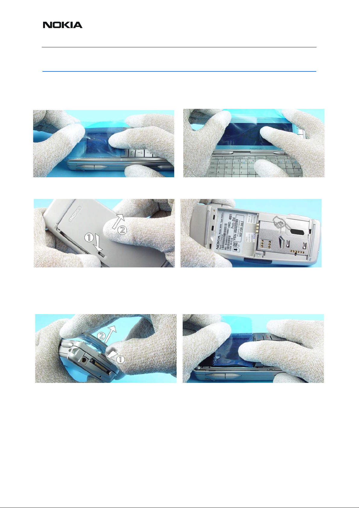
RAE-6/RA-4 Disassembly Instructions
(Also see the video clips on care point.)
1.) Protect the window with a film. 2.) Fit protective film to the LCD Module.
3.) Press down the Latch and open the Bat-
tery Cover.
5.) Push the Latch and open the A-Cover
Assy.
4.) Be sure that the battery is removed and
then continue with disassembly . Note to put
back the Sealing Tape after the re-assem-
bly.
6.) Protect the LCD Module with a film.
5 COMPANY CONFIDENTIAL Issue 1 12/04
Copyright © 2004 Nokia. All Rights Reserved.
Page 6

RAE-6/RA-4
5 - Disassembly/Reassembly Instructions Nokia Customer Care
7.) Remove the Keypad. Note the guide
openings on the UI Shield Assy when
assembling the Keypad.
9.) Unscrew the four, Torx Plus® size 6
screws in the shown order. Always use new
screws when re-assembling! For assembly,
reverse the order and use a Torx Plus® size
6 driver with a torque setting of 25Ncm.
8.) The screws are not reusable.
10.) Open the flap carefully by using the
dental tool.
11.) Remove the SHIELD in shown order. 12.) Remove the Power Key.
Issue 1 12/04 COMPANY CONFIDENTIAL 6
Copyright © 2004 Nokia. All Rights Reserved.
Page 7

RAE-6/RA-4
Nokia Customer Care 5 - Disassembly/Reassembly Instructions
13.) Push out the Speaker with SRT-6. 14.) Open the LCD connector carefully.
15.) Lift and remove the LCD Module. 16.) From shown side only, open the UI
Module connector carefully.
17.) Use the SRT-6 as a lever to lift the
18.) Hold the unit as shown in the picture.
Shield.
19.) Use a slotted screwdriver to unlock the
snap.
20.) The snap of the C-Cover is locked to
the Shield. Bend the snap a bit in the shown
direction and push it out carefully.
7 COMPANY CONFIDENTIAL Issue 1 12/04
Copyright © 2004 Nokia. All Rights Reserved.
Page 8

RAE-6/RA-4
5 - Disassembly/Reassembly Instructions Nokia Customer Care
21.) Press out the C-Cover Assy carefully. 22.) Take away the C-Cover Assy.
23.) The Command Buttons drop out by
pushing them out.
25.) Open the hooks carefully by using the
SRT-6 as a lever.
24.) Place the SRT-6 between Qwerty Key-
pad and the DC-Jack and lift the Qwerty
Keypad carefully.
26.) Unlock the hooks along the edge of the
Qwerty Keypad as shown.
27.) The same procedure on the shown
side.
Issue 1 12/04 COMPANY CONFIDENTIAL 8
Copyright © 2004 Nokia. All Rights Reserved.
28.) Now, the Qwerty Keypad can be
removed.
Page 9

RAE-6/RA-4
Nokia Customer Care 5 - Disassembly/Reassembly Instructions
For assembly only!
Always use a new Adhesive Qwerty Key-
pad when re-assembling!
30.) Remove the Chassis Assy. Always
start from the antenna side.
29.) Unscrew the eight, Torx Plus® size 6
screws in the order shown. Always use new
screws when re-assembling! For assembly,
reverse the order and use a Torx Plus® size
6 driver with a torque setting of 25Ncm.
31.) Remove the DC-Jack by using the DCplug.
32.) Remove the Microphone by using the
dental tool.
9 COMPANY CONFIDENTIAL Issue 1 12/04
Copyright © 2004 Nokia. All Rights Reserved.
33.) Note the placement of the RF Coax
Cable before continuing the disassembly.
Page 10

RAE-6/RA-4
5 - Disassembly/Reassembly Instructions Nokia Customer Care
34.) First remove the Antenna Assy. Do
Not open the Antenna RF connector!
35.) Remove the RF Coax Cable from its
guidance.
36.) Do not pull up on the cable. 37.) Lift RF connector straight up by using
angled tweezers, do not bend it sideways.
For Repair only!
RF Coax Cable cannot be disconnected
from the Antenna. If Antenna Assy or RF
38.) Unlock the flex connector with SRT-6
carefully.
Coax Cable is defect, use always a new
Antenna Assy and a new Coax Cable.
First place the Antenna Assy onto the
Shield and than connect the RF Coax
Cable.
Issue 1 12/04 COMPANY CONFIDENTIAL 10
Copyright © 2004 Nokia. All Rights Reserved.
Page 11

RAE-6/RA-4
Nokia Customer Care 5 - Disassembly/Reassembly Instructions
Unlock the connector carefully.
Turn the Engine Module. Take care of the
RF Gasket.
For assembly only!
Unscrew the Torx Plus® size 6 screw .
Remove the flex from the connector carefully.
For assembly only!
Place the Engine Module onto the Shield.
Take care of the RF Gasket.
Always use new screw when re-assembling!
For assembly use a Torx Plus® size 6 driver
with a torque setting of 25Ncm.
For assembly only!
Put the flex into the connector carefully by
using the flex assembly tape.
11 COMPANY CONFIDENTIAL Issue 1 12/04
Copyright © 2004 Nokia. All Rights Reserved.
For assembly only!
Lock the connector carefully and remove the
flex assembly tape.
Page 12

RAE-6/RA-4
5 - Disassembly/Reassembly Instructions Nokia Customer Care
39.) Remove the flex from the connector
carefully as shown in the picture. Do not fold
the flex foil
41.) Separate the Chassis from the Shield
carefully.
For assembly only!
40.) Unscrew the Torx Plus® size 6 screw .
42.) Swap unit
For assembly only!
Assemble the Chassis. Be careful and do
not damage the Hinge Pin and the flex.
Issue 1 12/04 COMPANY CONFIDENTIAL 12
Copyright © 2004 Nokia. All Rights Reserved.
For assembly use a Torx Plus
with a torque setting of 22Ncm.
®
size 6 driver
Page 13

RAE-6/RA-4
Nokia Customer Care 5 - Disassembly/Reassembly Instructions
For assembly only!
Place the flex into the connector carefully.
Be sure that the contacts are clean when
connecting the flex.
For assembly only!
Close the connector carefully.
13 COMPANY CONFIDENTIAL Issue 1 12/04
Copyright © 2004 Nokia. All Rights Reserved.
Page 14

RAE-6/RA-4
5 - Disassembly/Reassembly Instructions Nokia Customer Care
Reassembly
Reassembly should be in reverse order to disassembly unless otherwise stated.
Issue 1 12/04 COMPANY CONFIDENTIAL 14
Copyright © 2004 Nokia. All Rights Reserved.
 Loading...