

Page 1

PAMS Technical Documentation
RAE-5 Series PDA
7. Service Software
Instructions
Issue 1 04/02
Copyright 2002. Nokia Corporation. All Rights Reserved.
Page 2
RAE-5
PAMS
7. Service Software Instructions
AMENDMENT RECORD SHEET
Amendment
Number
Date Inserted By Comments
04/2002 OJuntunen
Technical Documentation
Page 7 – 2
Issue 1 04/02
Page 3

PAMS
RAE-5
Technical Documentation
7. Service Software Instructions
CONTENTS –Troubleshooting
Service Software 7 – 5. . . . . . . . . . . . . . . . . . . . . . . . . . . . . . . . . . . . . . . .
General 7 – 5. . . . . . . . . . . . . . . . . . . . . . . . . . . . . . . . . . . . . . . . . . . . .
Hardware requirements for Windows 3.1x 7 – 5. . . . . . . . . . .
Hardware requirements for Windows 95 7 – 5. . . . . . . . . . . .
Software Environment of the Support Modules 7 – 5. . . . . . . . .
Required Servicing Equipment 7 – 6. . . . . . . . . . . . . . . . . . . . . . .
Installation 7 – 7. . . . . . . . . . . . . . . . . . . . . . . . . . . . . . . . . . . . . . . .
Mechanical Connections 7 – 7. . . . . . . . . . . . . . . . . . . . . . . . . .
Installing the software on PC Hard Disk 7 – 7. . . . . . . . . . . . .
Common Properties of the User Interface 7 – 8. . . . . . . . . . . . . . . . . .
Login Dialog 7 – 8. . . . . . . . . . . . . . . . . . . . . . . . . . . . . . . . . . . . . . . . .
Main Window 7 – 9. . . . . . . . . . . . . . . . . . . . . . . . . . . . . . . . . . . . . . . .
Using Help 7 – 9. . . . . . . . . . . . . . . . . . . . . . . . . . . . . . . . . . . . . . . . . .
Page No
Software upgrade guide 7 – 10. . . . . . . . . . . . . . . . . . . . . . . . . . . . . . . . .
Equipment Setup instructions 7 – 10. . . . . . . . . . . . . . . . . . . . . . . . . .
Setting up the PC 7 – 11. . . . . . . . . . . . . . . . . . . . . . . . . . . . . . . . . .
Setting up BUS Configuration for WinTesla 7 – 11. . . . . . . . . . . .
Programming with WinTesla Interface 7 – 12. . . . . . . . . . . . . . . . . . .
WinTesla Interface 7 – 12. . . . . . . . . . . . . . . . . . . . . . . . . . . . . . . . .
Before programming 7 – 12. . . . . . . . . . . . . . . . . . . . . . . . . . . . . . . .
Programming procedure 7 – 12. . . . . . . . . . . . . . . . . . . . . . . . . . . .
ROM/MCU image 7 – 12. . . . . . . . . . . . . . . . . . . . . . . . . . . . . . . .
Installing All_Nokia_92XX_data_XX.SIS -package 7 – 18. . . . . .
Troubleshooting for the N9210 SW upgrade 7 – 20. . . . . . . . . . . . . .
Wintesla Tuning 7 – 22. . . . . . . . . . . . . . . . . . . . . . . . . . . . . . . . . . . . . . . .
RF tuning after repairs 7 – 22. . . . . . . . . . . . . . . . . . . . . . . . . . . . . . . .
Equipment Setup for RF Tuning without Removing Covers 7 – 23.
RX Calibration 7 – 24. . . . . . . . . . . . . . . . . . . . . . . . . . . . . . . . . . . . .
RX Filter Calibration (Automatic) 7 – 27. . . . . . . . . . . . . . . . . . . . .
RX AM Suppression (automatic) 7 – 29. . . . . . . . . . . . . . . . . . . . .
EGSM 7 – 29. . . . . . . . . . . . . . . . . . . . . . . . . . . . . . . . . . . . . . . . . .
PCN 7 – 31. . . . . . . . . . . . . . . . . . . . . . . . . . . . . . . . . . . . . . . . . . .
TX Power Tuning 7 – 33. . . . . . . . . . . . . . . . . . . . . . . . . . . . . . . . . . . . .
EGSM tuning 7 – 33. . . . . . . . . . . . . . . . . . . . . . . . . . . . . . . . . . . . . .
PCN tuning 7 – 35. . . . . . . . . . . . . . . . . . . . . . . . . . . . . . . . . . . . . . . .
TX I/Q Tuning 7 – 37. . . . . . . . . . . . . . . . . . . . . . . . . . . . . . . . . . . . . .
Common tuning procedure 7 – 38. . . . . . . . . . . . . . . . . . . . . . . .
Initial set–up PCN 7 – 39. . . . . . . . . . . . . . . . . . . . . . . . . . . . . . . .
IQ Tuning using Spectrum Analyzer 7 – 40. . . . . . . . . . . . . . . . . . . . .
EGSM 7 – 40. . . . . . . . . . . . . . . . . . . . . . . . . . . . . . . . . . . . . . . . . . . .
Issue 1 04/02
Page 7 – 3
Page 4

RAE-5
PAMS
7. Service Software Instructions
Spectrum Analyzer Settings 7 – 40. . . . . . . . . . . . . . . . . . . . . . .
Phone Settings 7 – 40. . . . . . . . . . . . . . . . . . . . . . . . . . . . . . . . . .
PCN 7 – 45. . . . . . . . . . . . . . . . . . . . . . . . . . . . . . . . . . . . . . . . . . . . . .
Spectrum Analyzer Settings 7 – 45. . . . . . . . . . . . . . . . . . . . . . .
Phone Settings 7 – 45. . . . . . . . . . . . . . . . . . . . . . . . . . . . . . . . . .
Energy Management (EM) Calibration 7 – 50. . . . . . . . . . . . . . . . . . .
Equipment Setup for Energy Management calibration 7 – 50. . .
Energy Management Calibration procedure 7 – 51. . . . . . . . . . . .
Technical Documentation
Page 7 – 4
Issue 1 04/02
Page 5

PAMS
RAE-5
Technical Documentation
Service Software
General
Wintesla software is used to perform service functions of the RAE-5 PDA. This
SW consists of Wintesla service software and product specific DLL’s
(Dynamically Linked Libraries).
To run WinTesla SW, a parallel port software protection device (PKD–1) must
be connected to the PC to perform flashing functions. If only controls are nec-
essary, RAE-5 can be controlled using equipment setup described in the Win-
Tesla RS chapter.
The test functions send test messages from PC to MS and receive results and
show them in the PC display. The messages to the phone can be sent via
DAU–9C cable.
Note: if this software is to be run on laptops, the power saving feature MUST be
switched off.
7. Service Software Instructions
Hardware requirements for Windows 3.1x
The recommended minimum hardware standard to run Service Software is any
computer which is 386 33 MHz or greater with at least 4 MB of memory and
VGA type display (640 x 480). This assumes that only the WinTesla with After
Sales Support Modules is active, i.e. other Windows packages are not running
in the background.
Hardware requirements for Windows 95
The recommended minimum hardware standard to run Service Software is any
computer which has Pentium processor, memory 8 MB and meets HW require-
ments recommended by Microsoft.
Software Environment of the Support Modules
The Service Software user interface is intended for the following environments:
Microsoft Windows 3.1x (enhanced mode) and Windows 95/98 and NT. De-
tailed information about Windows and application usage can be found from the
Microsoft Windows Users Guide.
As an ordinary Windows application, the main idea in the user interface is that
selections are made with menus, push buttons and shortcut keys. Selections
can be done by using keyboard and/or mouse. There is always a status bar dis-
played at the bottom of the main window which contains information about cur-
rent actions.
Issue 1 04/02
Page 7 – 5
Page 6

RAE-5
PAMS
7. Service Software Instructions
Technical Documentation
Required Servicing Equipment
– Computer: At least IBM 80386 or compatible with one unused serial port
*)
(COM1 or COM2)
– Operating System: DOS Version 3.2 or later
– If PCLStart in use: DOS 6.22 and IBM 80486 or compatible
– Display: Any 80–character text display
– Service software version for 3.5” disk (product code: 0774080)
Rest of the needed service equipment depends on what kind of operations service personnel wants to perform.
*)
Note: A number of PC’s of an older generation use the Intel, National Semiconductor, or United Microelectronics IC 8250 as the serial port UART. This is a comparatively inefficient circuit for current purposes
and does not necessarily support the M2BUS adapter at 9600 baud. The newer UART’s NS16450 and
NS16550AF of National Semiconductor offer solutions for these problems.
, one parallel port (LPT1), hard disk recommended
Page 7 – 6
Issue 1 04/02
Page 7

PAMS
RAE-5
Technical Documentation
Installation
Mechanical Connections
Caution: Make sure that you have switched off the PC and the printer before making connections.
Caution: Do not connect the PKD–1 key to the serial port. You may
damage your PKD–1 !
The software controls RAE-5 via a separate adapter connected to the serial
port of the PC, and to the phone bottom connector (DAU–9C cable).
Attach the dongle PKD–1 to the parallel port 1 (25–pin female D–connector) of
the PC. When connecting PKD–1 to the parallel port, be sure that you insert the
computer side of the PKD–1 to the PC (male side). If you use a printer on parallel port 1, install the PKD–1 between the PC and your printer cable.
The PKD–1 should not affect devices working with it. If some errors occur (errors in printing are possible) please try printing without the PKD–1. If printing is
OK without the PKD–1 please contact your dealer. We will offer you a new
PKD–1 in exchange for your old one.
7. Service Software Instructions
The program is delivered on a diskette and is copy protected with a dongle
PKD–1. It must be present in parallel port when using Service software.
Installing the software on PC Hard Disk
The program can also be installed on the hard disk, which is recommendable to
obtain a maximum data access rate.
Keep the original diskette safe to enable upgrading of the program !
If you plan to use PCL Start service software, you must install it before installing
Service software, see PCL Start installation instructions.
To install the new Service software program, follow the steps below:
1. insert the new Service software diskette
into drive A: of your computer
2. start Windows, and open File Manager
log into drive a:
3. start INSTALL.EXE and
install Service software to drive C:
type
A:
and press <Enter>
type C: and press <Enter>
To install product specific DLL’s, take your RAE-5 DLL disks, and repeat the
steps above.
Issue 1 04/02
Page 7 – 7
Page 8
RAE-5
PAMS
7. Service Software Instructions
Technical Documentation
Common Properties of the User Interface
This chapter describes how the User Interface CLF must appear to the user.
The User Interface MUST be capable of being driven without the use of a
mouse, as the service engineer rarely has space on the bench to use a mouse.
Login Dialog
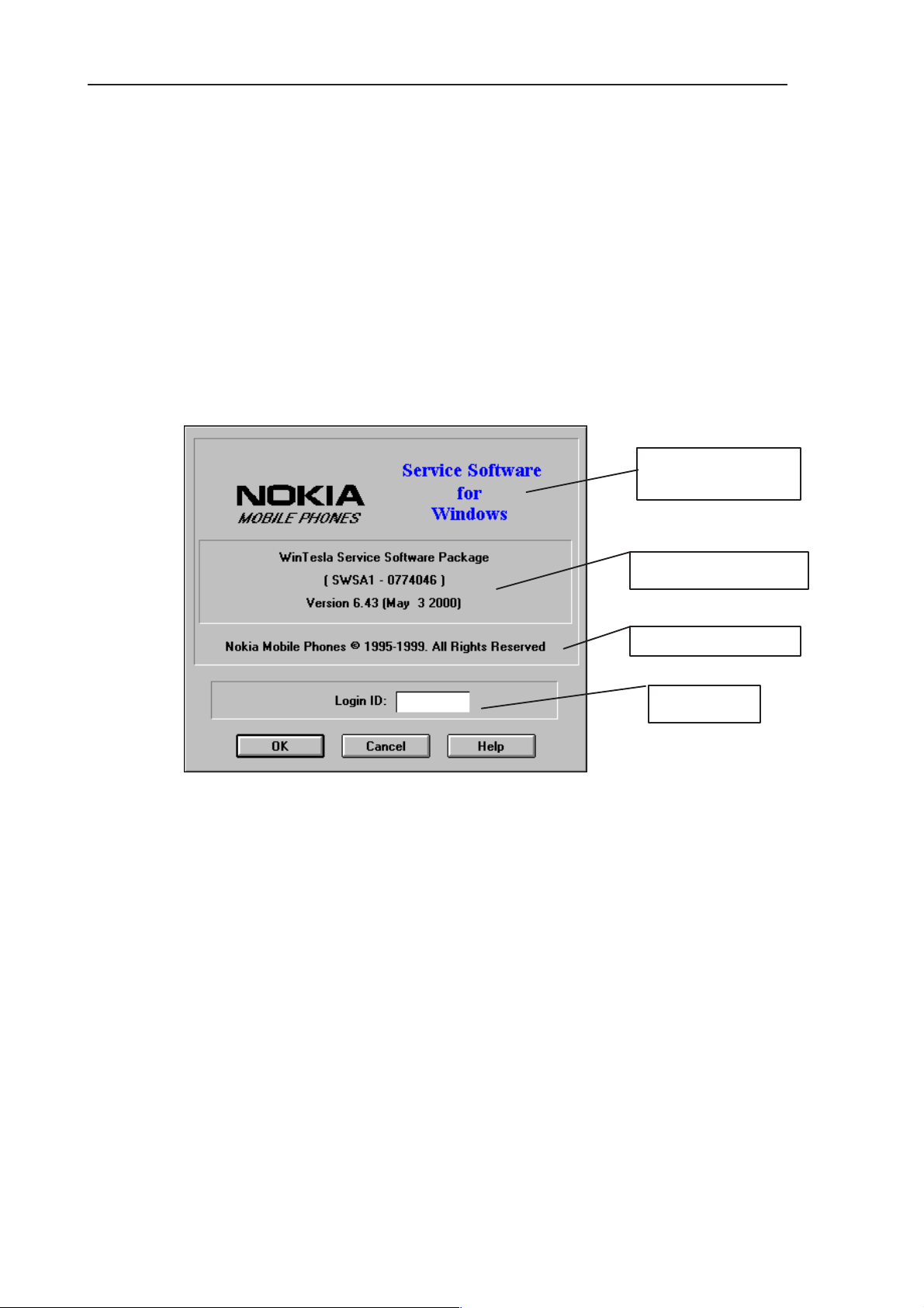
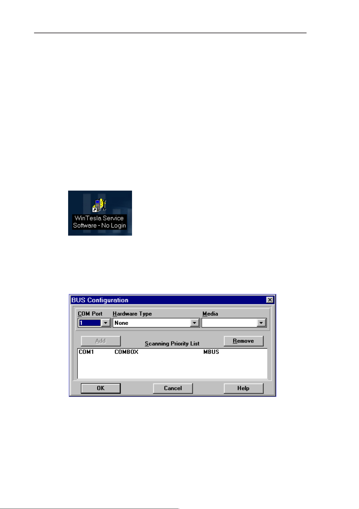
When the Service Software application is invoked, by checking on the Service
Software icon, the Login dialog box (Figure 1) will be displayed on the screen.
Nokia logo and
application name
Figure 1. Login dialog box
Nokia logo and application name bitmap (–)
Displays Nokia logo and name of the application.
Application version static text (–)
Contains the name and version of the application.
Copyright notice static text (–)
Copyright is informed as: “Nokia Mobile Phones (c) 1995–1999. All
Rights Reserved”.
Application version
Copyright version
Login box
Page 7 – 8
Login Box edit box (–)
The user Login ID edit box, where the user enters his faultlog user
name. (See Faultlog User Guide)
OK button (default key)
The user name is stored in memory and the dialog box is closed.
When the dialog box is closed, the application starts.
Issue 1 04/02
Page 9
PAMS
RAE-5
Technical Documentation
Cancel button (ESC)
The Dialog box is closed and application is started, but the Faultlog
feature is disabled.
Help button (F1)
Activates the Windows Help application and displays context sensitive Help.
Main Window
When Wintesla opens the basic screen, product specific DLL’s must be activated using mouse to select Product –> Open and select RAE-5
Using Help
7. Service Software Instructions
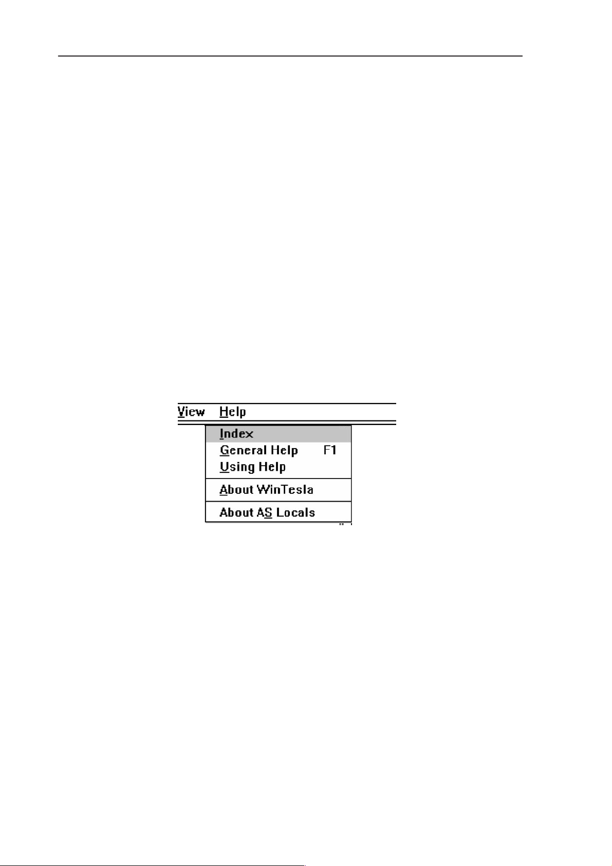
When DLL’s are active, the menu bar contains several items, including help
texts, as shown in Figure 2.
Figure 2. Menu bar
Instructions for service software use can be found in the help texts. Step by
step instructions for complex operations like SW upgrades and tunings can be
found in the end of this chapter.
Issue 1 04/02
Page 7 – 9
Page 10
RAE-5
PAMS
7. Service Software Instructions
Software upgrade guide
Equipment Setup instructions
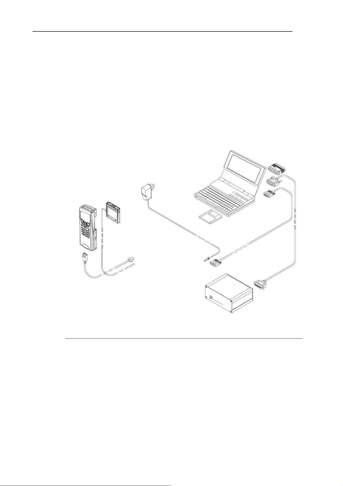
1. Once a FPS–8 box is used for the first time it has to be activated according
to the instructions included in the FPS–8 package.
2. Connect the box, cables and PC according to the drawing (see Figure 3)
2
Technical Documentation
7
8
5
6
1
Figure 3. Flashing setup
Item: Service accessory: Type Product code:
1 Prommer FPS–8 0750123
incl. 2 pcs 8MB SRAM module SF 12 0080346. . . . . . . . . . . . . . . . . . . .
2 AC/DC Adapter FRIWO (Included in FPS–8 sales pack)
FW7207/6 0680032. . . . . . . .
3 D9 – D9 Cable (Included in FPS–8 sales pack)
AXS–4 0730090. . . . . . . .
4 Printer Cable (Included in FPS–8 sales pack) 0730029
5 Service Battery BBL–3B 0770206
6 Service Cable SCH–8 0730137
7 Software protection key PKD–1 0750018
8 Service SW diskette 3.5” for Wintesla 0774046
9 Service SW diskette 3.5” for RAE-5 0775293
3
4
Page 7 – 10
Issue 1 04/02
Page 11
PAMS
RAE-5
Technical Documentation
Setting up the PC
1. Install dongle drivers from CD-ROM (d:\32bit_Dongle_Driver\dk2wn32.exe
–directory)
2. Install WinTesla version (version 6.43 or later) from CD-ROM (d:\wintesla\wt_inst.exe –directory)
3. Install the RAE-5 DLL’s from CD-ROM (d:\dlls\v04_X0_00\Disk1\setup.exe
–directory)
Setting up BUS Configuration for WinTesla
Once Wintesla is first time used the Connection from PC to FPS–8 has to be
configured according to the instructions bellow (see Figure 4, Figure 5).
1. Start WinTesla software (c:\WinTesla\Stesla.exe)
7. Service Software Instructions
Figure 4.
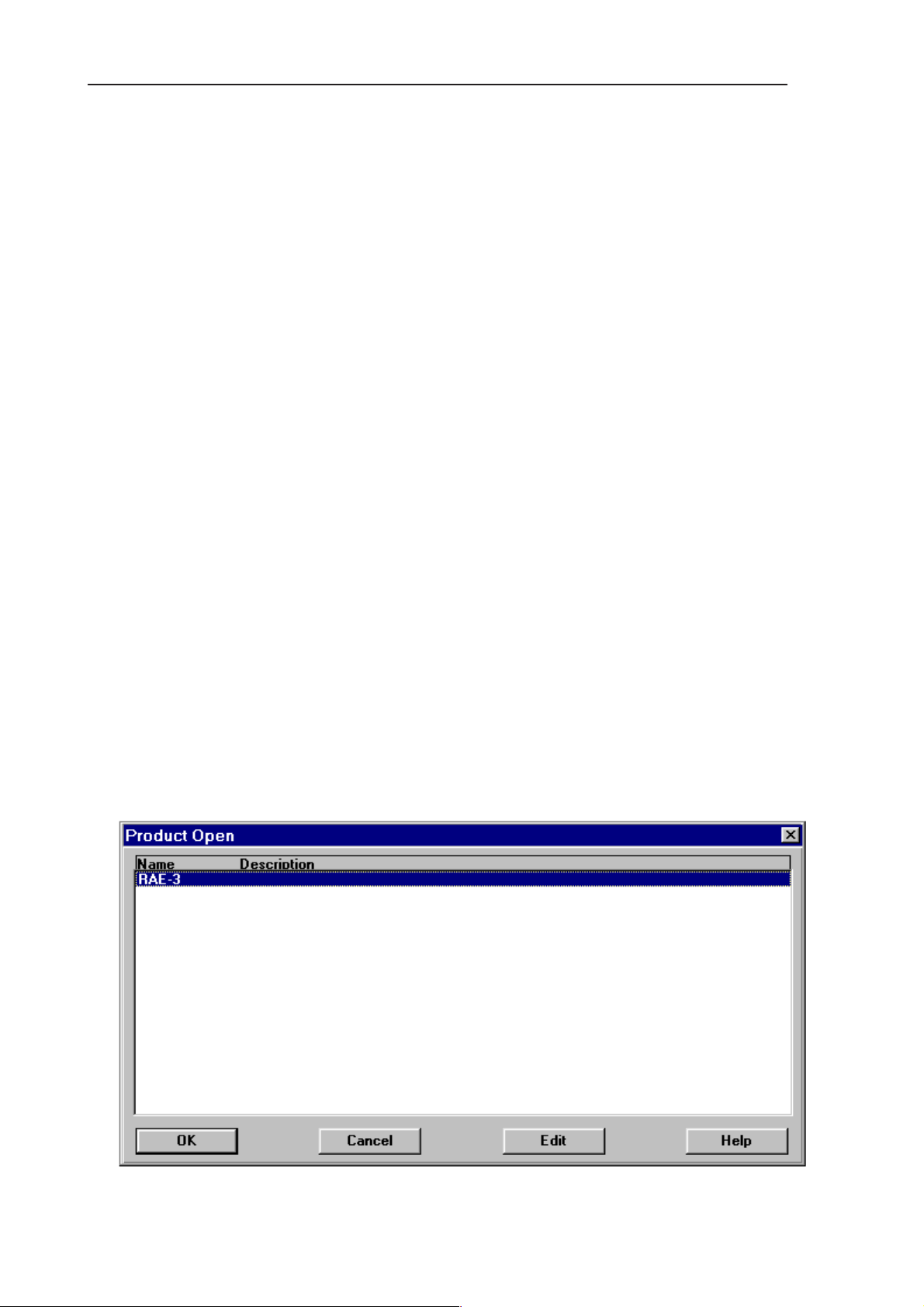
2. Set Bus Configuration for WinTesla according to Figure 2 below:
Open Bus Configuration –window by going ”Configure” –> ”Buses…”
Set COM port ”1” , Hardware Type ”COMBOX” and Media ”MBUS” (see
Figure 5 ).
Figure 5. Set Bus Configuration
Issue 1 04/02
Page 7 – 11
Page 12
RAE-5
PAMS
7. Service Software Instructions
Programming with WinTesla Interface
WinTesla Interface
These instructions are valid when using:
– WinTesla version 6.43 or later
– RAE-5, RAE–5 and RAB-3 AMS dll release v04.00.00 or later
– PKD–1 dongle
Before programming
Save backup data to memory card. Note that the memory card must be inserted in the Communicator.
1. Press the Office application button, select the File manager application and
press Open.
2. Press the Menu key and select
Memory card > Backkup to memory card...
Technical Documentation
3. Press Backup to backup all the Communicator data to the memory card.
Programming procedure
ROM/MCU image
1. Start WinTesla software
2. Insert BBL–3B service battery in the Communicator.
3. Connect SCH–8 cable to the Communicator bottom connector.
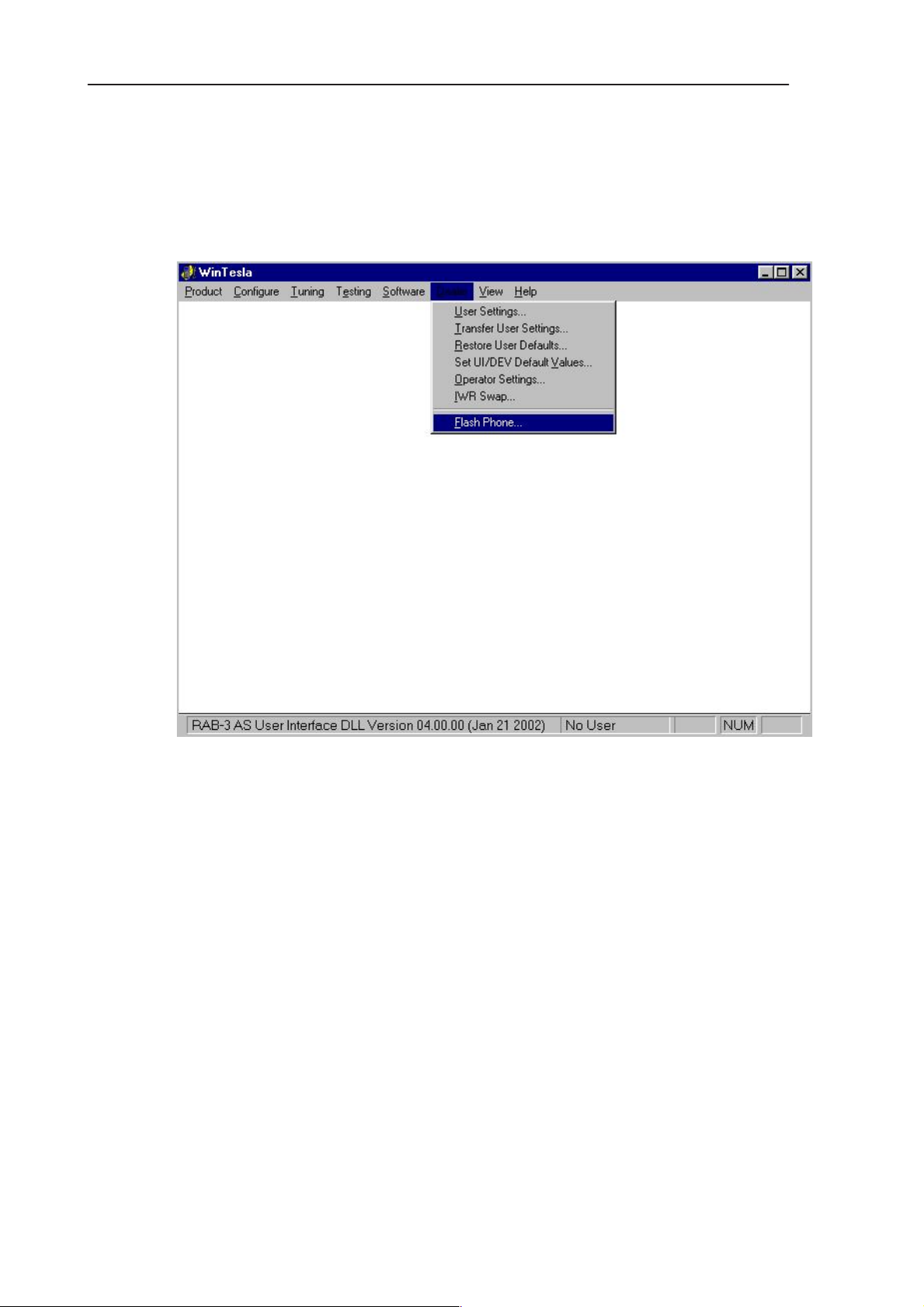
4. Select
Product –> Open –> RAE-5
for N9290 (see Figure 6)
Page 7 – 12
Figure 6. Product Open
Issue 1 04/02
Page 13
PAMS
RAE-5
Technical Documentation
Note: If Win Tesla is already running, and the Communicator is on, press ”F5”
to initialize connection.
2. Select
Dealer –> Flash Phone
7. Service Software Instructions
…
Figure 7. Wintesla user interface when the Communicator is running and initialization has
been successful.
Issue 1 04/02
Page 7 – 13
Page 14
RAE-5
PAMS
7. Service Software Instructions
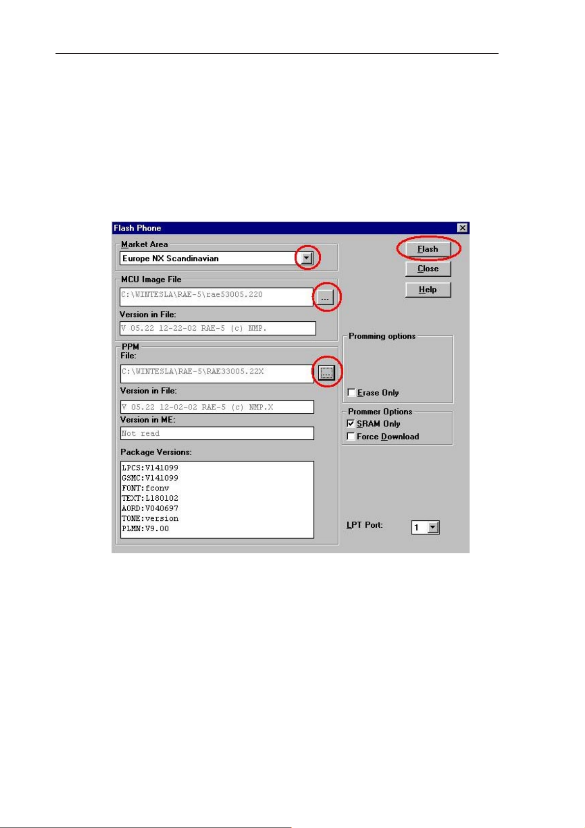
6.
7. Select
Flash Phone
Market Area
lower ’...’.. . . . . . . .
8. Select
MCU Image
is not automatically selected.. . . . . . . .
9. Press the Flash button (see Figure 8). . . . .
Technical Documentation
dialog opens.
(or select the correct PPM image by pressing the. . . . .
by pressing upper’...’ (if the correct MCU image . . . . .
Page 7 – 14
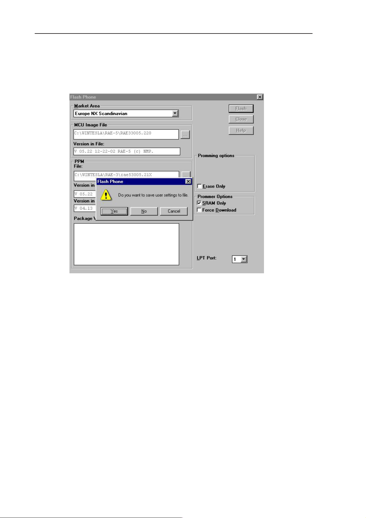
Figure 8. Flash phone –dialog
Issue 1 04/02
Page 15
PAMS
RAE-5
Technical Documentation
10 . Once the program is prompting for restoring user data choose NO if you do
not want to save the exixting user settings, else select YES . (see Figure 9)
7. Service Software Instructions
Figure 9. Saving user settings to file
11. Programming starts ( takes about 10 minutes)
Issue 1 04/02
Page 7 – 15
Page 16
RAE-5
PAMS
7. Service Software Instructions
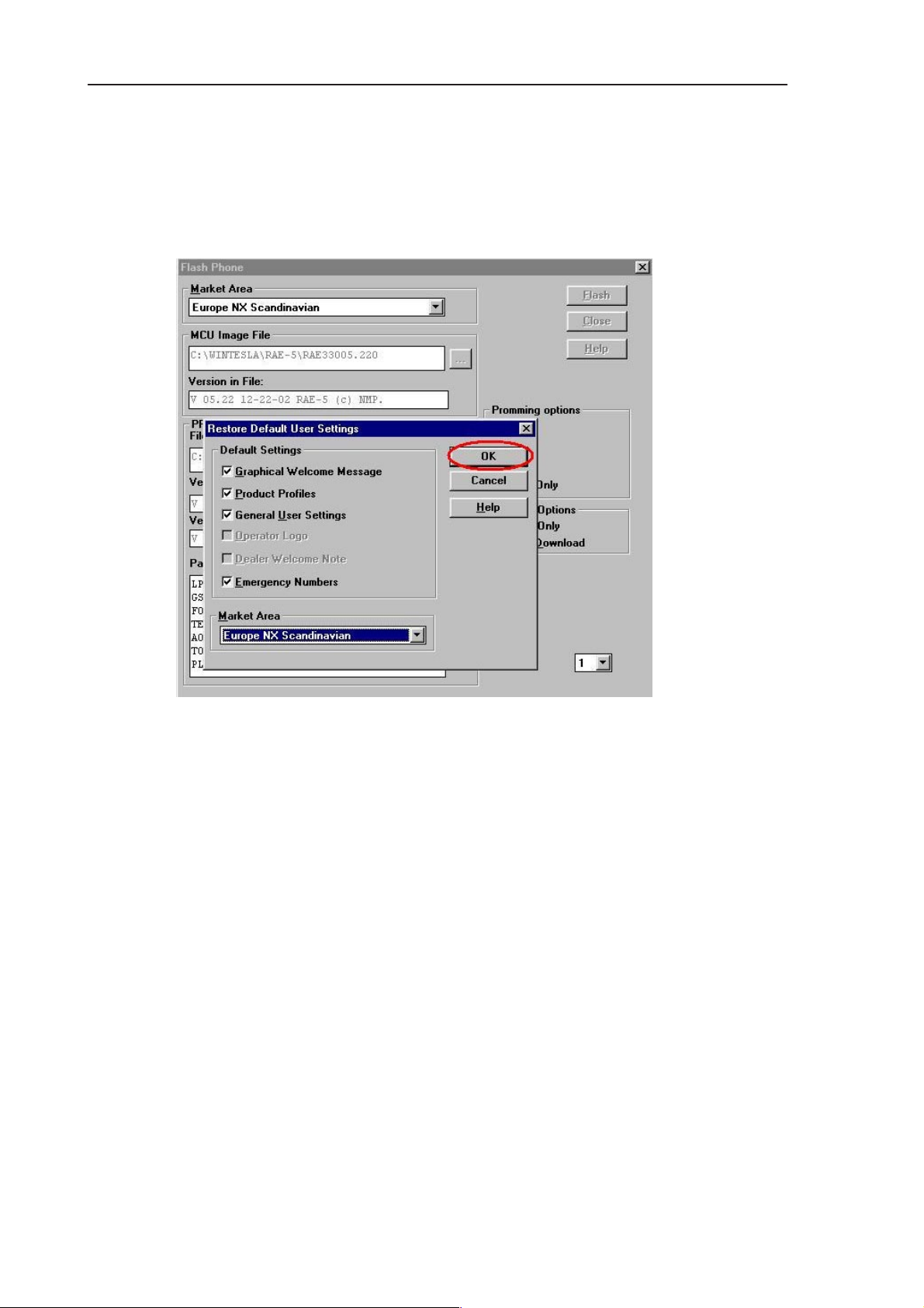
12. If you have selected NO to answer the previous question in step 10 the
user settings will be updated after flash programming . Press the OK button (
see Figure 10 .)
Technical Documentation
Figure 10. Restoring Default User settings
Page 7 – 16
Issue 1 04/02
Page 17

PAMS
RAE-5
Technical Documentation
13. After Flash programming complete message press OK button and
close the
Flash Phone
7. Service Software Instructions
dialog (see Figure 11)
Figure 11. Flash programming completed
14 Disconnect the BBL–3 service battery and the SCH–8 cable from the
Communicator.
Issue 1 04/02
Page 7 – 17
Page 18

RAE-5
PAMS
7. Service Software Instructions
Technical Documentation
Installing All_Nokia_92XX_data_XX.SIS -package
15. Insert the MMC that includes the correct SIS package. The same language
and version as in the ROM image (same as ’Market Area’ in Figure 8.)
16. Install All_Nokia_92XX_data_XX.SIS
– Open the Install/Remove program
– press the Extras application button
– Select the Control Panel application and then the Install/Remove applica-
tion.
– Install SIS package.
– Press Install new button
– Press Browse button,
– Select Memory card by pressing Arrow key once
– Press OK button
– Select All_Nokia_92XX_data_XX.SIS and press OK.
Page 7 – 18
Issue 1 04/02
Page 19

PAMS
RAE-5
Technical Documentation
After Programming
Restore data from the Memory Card.
– Press the Office application button, select the File Manager application and
press Open
– Press the Menu key and select
– Press Restore to restore all the backed–up memory card data to the Com-
municator.
Now you have new software in the Communicator !
7. Service Software Instructions
Menory card > Restore from memory card...
Issue 1 04/02
Page 7 – 19
Page 20

RAE-5
PAMS
7. Service Software Instructions
Technical Documentation
Troubleshooting for the N9210 SW upgrade
If something went wrong during flashing:
If you have a dead RAE-5
1. Do not try to switch phone on
2. Use product–> Open–> RAE-5. (Figure 12)
Wintesla will prompt you ” Did not find a phone in current connection! ” Answer
Yes.
Figure 12. Flash menu selection
3. Then use Dealer > Flash Phone (Figure 13)
Figure 13. Wintesla dialog when the RAE-5 is not running
4. Because user settings cannot be read, Wintesla will prompt you ”
Failed to communicate with phone. Settings cannot be saved. Do you want to
continue? ” Answer Yes.
Page 7 – 20
Issue 1 04/02
Page 21

PAMS
RAE-5
Technical Documentation
7. Service Software Instructions
Figure 14. Wintesla cannot read user settings
5. If Flash authority ID writing fails ( ) after flashing:
FPS–8 may not be activated,. . . . . . . .
Issue 1 04/02
Figure 15. Flash authority ID writing failed
Page 7 – 21
Page 22

RAE-5
PAMS
7. Service Software Instructions
Wintesla Tuning
Prior to any tuning the phone must be initialized:
Connect the phone to a PC with a DAU–9P cable
Start Wintesla–Service–Software and
Select P
Select: P
RF tuning after repairs
roduct Alt+p
roduct Alt+p
Technical Documentation
Open…
RAE-5
Initialize Alt+I
Normal Mode F5
Different repairs require different tuning. In general it is necessary to determine
in which section the repair was done to establish which tunings to perform. To
determine if RF tuning is necessary after repair it is important that the functionality of the repaired circuit is understood well. In case the circuit is not fully understood it might be wise to play it safe and do RF tunings in accordance with
the table below.
In general repairs in the TX part will require tuning of ”TX Power” and ”TX I/Q”
tuning.
In general repairs in the RX part or PLL will always require ”RX Calibration” and
in some cases require AM Suppression tuning (Automatic) and RX Filter Calibration (Automatic).
Other parts interfacing to TX, RX or PLL might require tuning, but common
sense should be used.
If it can be ruled out that a component change affects RF performance, e.g. the
microphone B200, there is no need to do any RF tuning.
Page 7 – 22
Issue 1 04/02
Page 23

PAMS
RAE-5
Technical Documentation
7. Service Software Instructions
Equipment Setup for RF Tuning without Removing Covers
2
6
5
1
3
Figure 16. Tuning set–up 1
Item: Service accessory: Type Product code:
1 Service car kit HCL–1 0770265
2 Service Battery BBL–3B 0770206
3 Modular T–Adapter 4626134
4 Service MBUS Cable DAU–9S 0730108
5 Software protection key PKD–1 0750018
6 Service SW diskette 3.5” for Wintesla 0774046
7 Service SW CD for RAE-5 0775291
4
Issue 1 04/02
Page 7 – 23
Page 24

RAE-5
PAMS
7. Service Software Instructions
RX Calibration
The ”RX calibration” is used to determine gain at different gain–settings for
front–end and Hagar and needs to be done in both bands, but the calibration
only have to be started once, it will automatically proceed to the PCN band after
EGSM.
Select: T
uning Alt+t
Technical Documentation
R
X Calibration r
947.06771MHz
Figure 17.
Note:
Always use the latest Wintesla support DLLs
Connect an external generator to the phones RF connector and set the generator as the window tells you.
Click OK in the Wintesla window, now a new window pops up:
Change the level on the generator as the window tells you.
Click OK in the Wintesla window, now a new window pops up:
947.06771 MHz
–86.00000
Page 7 – 24
Figure 18.
Issue 1 04/02
Page 25

PAMS
RAE-5
Technical Documentation
7. Service Software Instructions
Figure 19.
Difference between the gain steps should be 10dB1dB .
Change the level and frequency on the generator as the window tells you.
Click OK in the Wintesla window, now a new window pops up:
Figure 20.
Change the level and frequency on the generator as the window tells you.
Click OK in the Wintesla window, now a new window pops up:
Issue 1 04/02
Page 7 – 25
Page 26

RAE-5
PAMS
7. Service Software Instructions
Change the level and frequency on the generator as the window tells you.
Click OK in the Wintesla window, now a new window pops up:
Technical Documentation
.86.000000
Figure 21.
Difference between the gain steps should be 10dB1dB .
Click S
RX calibration is now completed.
Page 7 – 26
Figure 22.
ave in the Wintesla window.
Issue 1 04/02
Page 27

PAMS
RAE-5
Technical Documentation
RX Filter Calibration (Automatic)
This calibration is calibrating the Baseband filter inside Hagar, for this reason
the calibration is not done in both bands.
Select: T
A window now pops–up:
uning Alt+t
7. Service Software Instructions
R
X Measurements
In the ”Select Function” frame select RX ”Filter calibration (Automatic)”. No external signal is needed for this, just click ”M
then click ”Save Defaults”.
Issue 1 04/02
Figure 23.
easure”, wait a few seconds and
Page 7 – 27
Page 28

RAE-5
PAMS
7. Service Software Instructions
Technical Documentation
Figure 24.
RX filter calibration is now completed and the ”RX Measurements” window can
be closed by clicking ”Close”
Page 7 – 28
Issue 1 04/02
Page 29

PAMS
RAE-5
Technical Documentation
RX AM Suppression (automatic)
This calibration is tuning the AM suppression performance of Hagar mixers and
will have to be done in both bands. If flash or Hagar have been replaced or Full
Factory settings have been performed RX AM Suppression must be done.
EGSM
Select: P
Select: T
A window now pops–up:
roduct Alt+p
B
and b
uning Alt+t
7. Service Software Instructions
E
GSM e
R
X Measurements
In the ”Select Function” frame select RX ”RX AM Suppression (Automatic)”.
Issue 1 04/02
Figure 25.
Page 7 – 29
Page 30

RAE-5
PAMS
7. Service Software Instructions
Click M
Note:
easure, A window now pops–up:
Always use the latest Wintesla support DLLs
Connect an external generator to the antenna connector of the phone and set–
up the generator.
Technical Documentation
Figure 26.
Click OK in the Wintesla window, the RSSI value is updated in the RX Measurements window.
Click ”Save ”. The ”RX AM suppression tuning” is now completed in EGSM.
Page 7 – 30
Figure 27.
Issue 1 04/02
Page 31

PAMS
RAE-5
Technical Documentation
PCN
Select: P
Select: T
roduct Alt+p
uning Alt+t
A window now pops–up:
7. Service Software Instructions
and b
B
PCN p
X Measurements
R
In the ”Select Function” frame select function ”RX AM Suppression (Automatic)”
Click M
Issue 1 04/02
Figure 28.
easure, A window now pops–up:
Figure 29.
Page 7 – 31
Page 32

RAE-5
PAMS
7. Service Software Instructions
Note:
Always use the latest Wintesla support DLLs
Connect an external generator to the antenna connector of the phone and set–
up the generator.
Click OK in the Wintesla window, the RSSI value is updated in the RX Measurements window.
Technical Documentation
Figure 30.
Click ”Save ”. The ”RX AM suppression tuning” is now completed in PCN.
Page 7 – 32
Issue 1 04/02
Page 33

PAMS
RAE-5
Technical Documentation
TX Power Tuning
This tuning must be done in both bands.
TX Power tuning must be done with a peak power meter,
Note:
e.g. Rohde & Schwarz model NRVD with a Rohde & Schwarz Peak Power
Sensor TDMA Model NRV–Z31 and a suitable attenuator.
The use of power meter in GSM testers is likely to cause larger error than the
use of a dedicated power meter and might cause the phone to be non–compliant with GSM specifications.
EGSM tuning
Select: Product Alt+p
7. Service Software Instructions
and b
B
E
GSM e
Select: Te
A window now pops–up (Figure 31):
sting Alt+e
F Controls r
R
Issue 1 04/02
Figure 31. RF Controls
Page 7 – 33
Page 34

RAE-5
PAMS
7. Service Software Instructions
Set Active unit to T
Set TX D
Click A
ata Type: to Rand
pply
X
Click Close
Select: T
uning Alt+t
A window now pops–up (Figure 32):
TX P
ower… Alt+P
Technical Documentation
Tune levels 19, 15, 5 and Base in accordance with the target values.
Click calculate, check if the other levels match the targets, correct if necessary.
Click S
Page 7 – 34
Figure 32.
ave when all values matches the targets.
Issue 1 04/02
Page 35

PAMS
RAE-5
Technical Documentation
PCN tuning
Select: Product Alt+p
Select: Te
A window now pops–up (Figure 33):
sting Alt+e
7. Service Software Instructions
and b
B
P
CN p
F Controls r
R
Set Active unit to TX
Set TX D
Click A
Click Close
Select: Tuning Alt+t
Issue 1 04/02
ata Type: to Rand
pply
Figure 33.
ower… Alt+P
TX P
Page 7 – 35
Page 36

RAE-5
PAMS
7. Service Software Instructions
A window now pops–up:
Technical Documentation
Figure 34.
Tune levels 15, 11, 0 and Base in accordance with the target values.
Click calculate, check if the other levels match the targets, correct if necessary.
Click S
ave when all values matches the targets.
Page 7 – 36
Issue 1 04/02
Page 37

PAMS
RAE-5
Technical Documentation
TX I/Q Tuning
This tuning must be done in both bands.
Select: P
Select: Te
A new pop up window appears
roduct Alt+p
sting Alt+e
7. Service Software Instructions
and b
B
E
GSM e
R
F Controls r
Set Active unit to TX
Set TX D
Click A
Click Close and continue to next stage
Issue 1 04/02
Figure 35.
ata Type: to Cont1
pply
Page 7 – 37
Page 38

RAE-5
PAMS
7. Service Software Instructions
Common tuning procedure
Select: T
uning Alt+t
A window now pops–up (Figure 36) :
TX I/Q
Technical Documentation
… Alt+q
Figure 36.
The carrier and +67kHz signal should now be tuned to a minimum. (Figure 37)
The buttons in the ”TX I and Q DC Offset:” will change the level of the carrier.
The buttons in the ”Amplitude and Phase Difference:” window will change the
level of the +67kHz signal.
When minimum values are reached, click S
ave.
Page 7 – 38
Figure 37.
Issue 1 04/02
Page 39

PAMS
RAE-5
Technical Documentation
Initial set–up PCN
Select: P
Select: Te
roduct Alt+p
sting Alt+e
A window now pops–up (Figure 38):
B
and b
P
CN p
R
F Controls r
7. Service Software Instructions
Set Active unit to TX
Set TX D
Click A
Click Close and continue to next section
Issue 1 04/02
Figure 38.
ata Type: to Cont1
pply
Page 7 – 39
Page 40

RAE-5
PAMS
7. Service Software Instructions
IQ Tuning using Spectrum Analyzer
EGSM
Spectrum Analyzer Settings
Use an appropriate attenuator 10 or 20dB insertion loss and set the Reference
Level Offset according to insertion loss from the phone to the Spectrum Analyzer.
Set the Spectrum Analyzer according to the following settings.
Parameter EGSM
Center frequency 902 MHz
Frequency span 300 kHz
Resolution Bandwidth 3 kHz
Technical Documentation
Video Bandwidth 3 kHz
Sweep time 3 s
Detector type Max. peak
reference level 35 dBm
Marker 1 902.06771 MHz
Marker 2 902 MHz
Marker 3 901.93229 MHz
Phone Settings
Connect the phone to the computer and to the Spectrum Analyzer.
Using WinTesla to select the following:
Product
This selects the EGSM band. Then select the following:
Te
sting
B
and
GSM
E
Page 7 – 40
R
F Controls…
Issue 1 04/02
Page 41

PAMS
RAE-5
Technical Documentation
A window pops up (Figure 39):
7. Service Software Instructions
Figure 39.
Set ”TX Data Type” to ”Cont1”, press ”Apply”, then press ”Close”. The window
closes.
Select the following:
Tuning
Tx I/Q
…
Issue 1 04/02
Page 7 – 41
Page 42

RAE-5
PAMS
7. Service Software Instructions
A window pops up:
This is the ”Tx I/Q Tuning” window.
Set the Power Level to ”10”. Then the Spectrum Analyzer shows a plot like this
(Figure 41):
Technical Documentation
Figure 40.
Marker 1 shows the wanted signal. Marker 2 and marker 3 show the unwanted
signals.
Page 7 – 42
Figure 41.
Issue 1 04/02
Page 43

PAMS
RAE-5
Technical Documentation
In the ”Tx I/Q Tuning” window use ”TX I
adjust the spurious at 902.0MHz (Marker 2) to the minimum level.
Then the Spectrum Analyzer shows a plot like this (Figure 43):
7. Service Software Instructions
DC Offset” and ”TX Q DC Offset” to
Figure 42.
In the ”Tx I/Q Tuning” window use ”Amplitude Difference” and ”Phase Difference” to adjust the spurious at 901.93229 MHz (Marker 3) to the minimum level.
Issue 1 04/02
Figure 43.
Page 7 – 43
Page 44

RAE-5
PAMS
7. Service Software Instructions
Then the Spectrum Analyzer shows a plot like this (Figure 45):
Technical Documentation
Figure 44.
In the ”Tx I/Q Tuning” window press ”Save” and the optimal values are stored in
the phone. The window closes.
Note: The optimal values for ”TX I and Q Offset” and ”Amplitude and
Phase Difference” vary from phone to phone.
Page 7 – 44
Figure 45.
Issue 1 04/02
Page 45

PAMS
RAE-5
Technical Documentation
PCN
Spectrum Analyzer Settings
Use an appropriate attenuator 10 or 20dB insertion loss and set the Reference
Level Offset according to insertion loss from the phone to the Spectrum Analyzer.
Set the Spectrum Analyzer according to the following settings.
Parameter PCN
Center frequency 1747.8 MHz
Frequency span 300 kHz
Resolution Bandwidth 3 kHz
Video Bandwidth 3 kHz
Sweep time 3 s
7. Service Software Instructions
Detector type Max. peak
reference level 35 dBm
Marker 1 1747.73229 MHz
Marker 2 1747.8 MHz
Marker 3 1747.86771 MHz
Phone Settings
Connect the phone to the computer and to the Spectrum Analyzer.
Using WinTesla to select the following:
Product
This activates the PCN band. Then select the following:
Te
sting
B
and
R
F Controls…
P
CN
Issue 1 04/02
Page 7 – 45
Page 46

RAE-5
PAMS
7. Service Software Instructions
A window pops up:
Technical Documentation
Figure 46.
Set ”TX Data Type” to ”Cont1”, press ”Apply”, then press ”Close”. The window
closes.
Select the following:
Tuning
Tx I/Q
…
A window pops up:
Figure 47.
Select ”EEPROM Values” and a new window pops up:
Page 7 – 46
Issue 1 04/02
Page 47

PAMS
RAE-5
Technical Documentation
This is the ”Tx I/Q Tuning” window.
Set the Power Level to ”5”. Then the Spectrum Analyzer shows a plot like this
(Figure 49):
7. Service Software Instructions
Figure 48.
Issue 1 04/02
Figure 49.
Page 7 – 47
Page 48

RAE-5
PAMS
7. Service Software Instructions
In the ”Tx I/Q Tuning” window use ”TX I
adjust the spurious at 1747.8MHz (Marker 2) to the minimum level.
Technical Documentation
DC Offset” and ”TX Q DC Offset” to
Figure 50.
Then the Spectrum Analyzer shows a plot like this (Figure 51):
Marker 1 shows the wanted signal. Marker 2 and marker 3 show the unwanted
signals.
Page 7 – 48
Figure 51.
Issue 1 04/02
Page 49

PAMS
RAE-5
Technical Documentation
In the ”Tx I/Q Tuning” window use ”A
ence” to adjust the spurious at 1747.86771MHz (Marker 3) to the minimum level.
7. Service Software Instructions
mplitude Difference” and ”Phase Differ-
Figure 52.
Then the Spectrum Analyzer shows a plot like this:
In the ”Tx I/Q Tuning” window press ”Save” and the optimal values are stored in
the phone. The window closes.
Note:
Phase Difference” vary from phone to phone.
Issue 1 04/02
Figure 53.
The optimal values for ”TX I and Q Offset” and ”Amplitude and
Page 7 – 49
Page 50

RAE-5
PAMS
7. Service Software Instructions
Technical Documentation
Energy Management (EM) Calibration
Equipment Setup for Energy Management calibration
NOTE: EM values can not be tuned in module jig MJS–14
1.
4
5
2
6. and 7.
3
Figure 54. Tuning set–up 2
Item: Service accessory: Type Product code:
1 Dummy Service Battery BBL–3B 0770206
2 DC Cable SCB–3 0730114
3 Service MBUS Cable DAU–9C 0730138
4 Calibration unit JBE–2 0775290
5 Software protection key PKD–1 0750018
6 Service SW diskette 3.5” for Wintesla 0774046
7 Service SW CD for RAE-5 0775291
Page 7 – 50
Issue 1 04/02
Page 51

PAMS
RAE-5
Technical Documentation
Energy Management Calibration procedure
NOTE: This can not be done in module jig MJS–14. EM calibration is possible
only when phone is completely assembled.
– Connect DAU-9C cable and BBL-3B battery to the Communicator
– Connect BBL-3B to the calibration unit JBE-2 and DC cable SCB-3 between
phone and calibration unit.
– Connect JBE-2 to laboratory power supply which is adjusted to 8.0V
– Start Wintesla service SW
– Select Tuning –> Energy Management Calibration
– Run calibrations separately or all at once as described in the following list.
Connect 10.5V to the calibration unit JBE-2 as prompted by service SW.
– Select calibrations:
– Select 1.Run Battery & charger default values checkbox
7. Service Software Instructions
– Select 2.Battery voltage checkbox
– Select 3.Charger voltage checkbox
– Select 4.Battery size checkbox
– Select 5.Battery temperature checkbox
– Select 6.Charge current
– Select Save without confirmation, if you don’t want
confirm all the selected calibration values before saving
– Run calibrations by pressing Run button
– Set supply voltage back to 8.0 V
Issue 1 04/02
Page 7 – 51
Page 52

RAE-5
PAMS
7. Service Software Instructions
Technical Documentation
This page intentionally left blank.
Page 7 – 52
Issue 1 04/02
 Loading...