

Page 1

PAMS Technical Documentation
RAE-3 Series PDA
6. Service Tools
Issue1 06/01
Copyright 2001. Nokia Mobile Phones. All Rights Reserved.
Page 2

RAE-3
PAMS
6. Service Tools
Amendment
Number
Technical Documentation
AMENDMENT RECORD SHEET
Date Inserted By Comments
06/01 OJuntunen
Page 6 – 2
Issue1 06/01
Page 3

PAMS
RAE-3
Technical Documentation
CONTENTS –Troubleshooting
Module Jig MJS–14 6 – 5. . . . . . . . . . . . . . . . . . . . . . . . . . . . . . . . . . .
Product Code 6 – 5. . . . . . . . . . . . . . . . . . . . . . . . . . . . . . . . . . . . . .
Views of MJS–14 6 – 5. . . . . . . . . . . . . . . . . . . . . . . . . . . . . . . . . . .
User Guide for MJS-14 6 – 7. . . . . . . . . . . . . . . . . . . . . . . . . . . . . . . . . .
Warnings: 6 – 7. . . . . . . . . . . . . . . . . . . . . . . . . . . . . . . . . . . . . . . . . . .
High Voltage 6 – 7. . . . . . . . . . . . . . . . . . . . . . . . . . . . . . . . . . . . . . .
Power Source 6 – 7. . . . . . . . . . . . . . . . . . . . . . . . . . . . . . . . . . . . .
Flash Mode vs. EPOC Running –mode 6 – 7. . . . . . . . . . . . . . .
External Connections 6 – 7. . . . . . . . . . . . . . . . . . . . . . . . . . . . . . . . .
RF 6 – 7. . . . . . . . . . . . . . . . . . . . . . . . . . . . . . . . . . . . . . . . . . . . . . .
System Signals 6 – 7. . . . . . . . . . . . . . . . . . . . . . . . . . . . . . . . . . . .
Audio Signals 6 – 7. . . . . . . . . . . . . . . . . . . . . . . . . . . . . . . . . . . . . .
Input Terminals 6 – 7. . . . . . . . . . . . . . . . . . . . . . . . . . . . . . . . . . . .
Detection Switches 6 – 8. . . . . . . . . . . . . . . . . . . . . . . . . . . . . . . . . . .
Starting 6 – 8. . . . . . . . . . . . . . . . . . . . . . . . . . . . . . . . . . . . . . . . . . . . .
Power ON 6 – 8. . . . . . . . . . . . . . . . . . . . . . . . . . . . . . . . . . . . . . . . . . .
Default State 6 – 8. . . . . . . . . . . . . . . . . . . . . . . . . . . . . . . . . . . . . .
EPOC Running State 6 – 8. . . . . . . . . . . . . . . . . . . . . . . . . . . . . . .
In Use 6 – 8. . . . . . . . . . . . . . . . . . . . . . . . . . . . . . . . . . . . . . . . . . . . . .
Finishing 6 – 9. . . . . . . . . . . . . . . . . . . . . . . . . . . . . . . . . . . . . . . . . . . .
Signals in Board to Board Adapter JC4 6 – 9. . . . . . . . . . . . . . . . . .
Flash Prommer FPS-8 (Sales Pack) 6 – 11. . . . . . . . . . . . . . . . . . . .
Product Code 6 – 11. . . . . . . . . . . . . . . . . . . . . . . . . . . . . . . . . . . . . .
View of FPS-8 6 – 11. . . . . . . . . . . . . . . . . . . . . . . . . . . . . . . . . . . . .
Calibration Unit JBE-2 6 – 12. . . . . . . . . . . . . . . . . . . . . . . . . . . . . . . . .
Product Code 6 – 12. . . . . . . . . . . . . . . . . . . . . . . . . . . . . . . . . . . . . .
View of JBE–2 6 – 12. . . . . . . . . . . . . . . . . . . . . . . . . . . . . . . . . . . . .
6. Service Tools
Page No
User Guide for JBE-2 6 – 13. . . . . . . . . . . . . . . . . . . . . . . . . . . . . . . . . . . .
Service Operations 6 – 13. . . . . . . . . . . . . . . . . . . . . . . . . . . . . . . . . . .
Power Management Calibrations 6 – 13. . . . . . . . . . . . . . . . . . . . . . .
Service Car Kit HCL-1 6 – 14. . . . . . . . . . . . . . . . . . . . . . . . . . . . . . . . .
Product Code 6 – 14. . . . . . . . . . . . . . . . . . . . . . . . . . . . . . . . . . . . . .
View of HCL-1 6 – 14. . . . . . . . . . . . . . . . . . . . . . . . . . . . . . . . . . . . .
User Guide for HCL-1 6 – 15. . . . . . . . . . . . . . . . . . . . . . . . . . . . . . . . . . .
Connection to Service SW 6 – 15. . . . . . . . . . . . . . . . . . . . . . . . . . . . .
Allowed Power Sources 6 – 15. . . . . . . . . . . . . . . . . . . . . . . . . . . . . . .
About Tuning 6 – 15. . . . . . . . . . . . . . . . . . . . . . . . . . . . . . . . . . . . . . . .
Dummy Service Battery BBL-3B 6 – 16. . . . . . . . . . . . . . . . . . . . . . . .
Product Code 6 – 16. . . . . . . . . . . . . . . . . . . . . . . . . . . . . . . . . . . . . .
View of BBL-3 6 – 16. . . . . . . . . . . . . . . . . . . . . . . . . . . . . . . . . . . . .
Issue1 06/01
Page 6 – 3
Page 4

RAE-3
PAMS
6. Service Tools
D9-D9 Cable AXS-4 6 – 17. . . . . . . . . . . . . . . . . . . . . . . . . . . . . . . . . .
Product Code 6 – 17. . . . . . . . . . . . . . . . . . . . . . . . . . . . . . . . . . . . . .
View of AXS-4 6 – 17. . . . . . . . . . . . . . . . . . . . . . . . . . . . . . . . . . . . .
MBUS Cable DAU–9C 6 – 18. . . . . . . . . . . . . . . . . . . . . . . . . . . . . . . .
Product Code 6 – 18. . . . . . . . . . . . . . . . . . . . . . . . . . . . . . . . . . . . . .
View of DAU–9C 6 – 18. . . . . . . . . . . . . . . . . . . . . . . . . . . . . . . . . . .
MBUS Cable DAU-9S 6 – 18. . . . . . . . . . . . . . . . . . . . . . . . . . . . . . . . .
Product Code 6 – 18. . . . . . . . . . . . . . . . . . . . . . . . . . . . . . . . . . . . . .
View of DAU-9S 6 – 18. . . . . . . . . . . . . . . . . . . . . . . . . . . . . . . . . . . .
DC Cable SCB–3 6 – 19. . . . . . . . . . . . . . . . . . . . . . . . . . . . . . . . . . . . .
Product Code 6 – 19. . . . . . . . . . . . . . . . . . . . . . . . . . . . . . . . . . . . . .
View of SCB–3 6 – 19. . . . . . . . . . . . . . . . . . . . . . . . . . . . . . . . . . . . .
Service Cable SCH-8 6 – 19. . . . . . . . . . . . . . . . . . . . . . . . . . . . . . . . .
Product Code 6 – 19. . . . . . . . . . . . . . . . . . . . . . . . . . . . . . . . . . . . . .
View of SCH-8 6 – 19. . . . . . . . . . . . . . . . . . . . . . . . . . . . . . . . . . . . .
Power ACH-6 6 – 20. . . . . . . . . . . . . . . . . . . . . . . . . . . . . . . . . . . . . . . .
Product Code 6 – 20. . . . . . . . . . . . . . . . . . . . . . . . . . . . . . . . . . . . . .
Views of ACH-6 6 – 20. . . . . . . . . . . . . . . . . . . . . . . . . . . . . . . . . . . .
SW Security Device PKD-1 6 – 21. . . . . . . . . . . . . . . . . . . . . . . . . . . .
Product Code 6 – 21. . . . . . . . . . . . . . . . . . . . . . . . . . . . . . . . . . . . . .
View of SW Security Device 6 – 21. . . . . . . . . . . . . . . . . . . . . . . . .
Modular T–adapter 6 – 21. . . . . . . . . . . . . . . . . . . . . . . . . . . . . . . . . . .
Product Code 6 – 21. . . . . . . . . . . . . . . . . . . . . . . . . . . . . . . . . . . . . .
View of Modular T–adapter 6 – 21. . . . . . . . . . . . . . . . . . . . . . . . . .
Technical Documentation
Page 6 – 4
Issue1 06/01
Page 5
PAMS
RAE-3
Technical Documentation
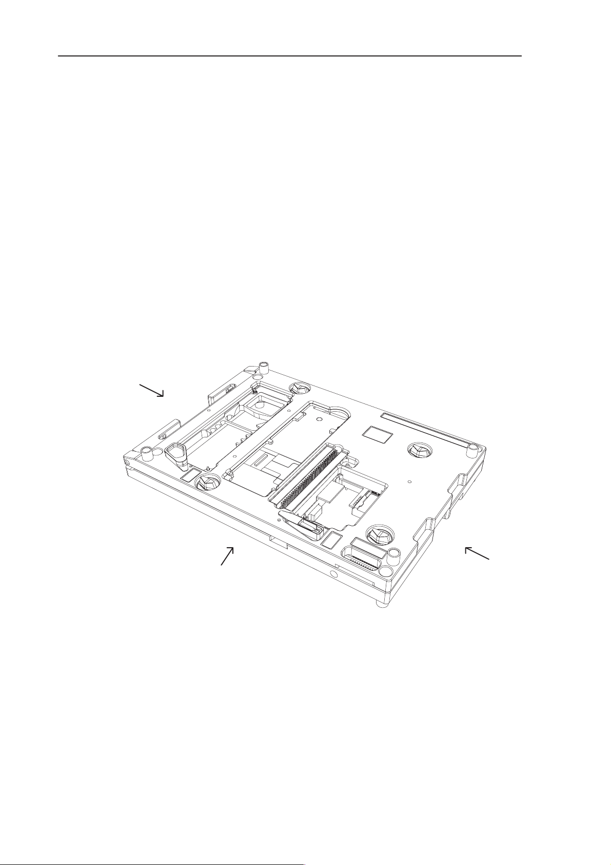
Module Jig MJS–14
The module jig MJS–4 is used for RAE–3 module testing and repairing. There
are slots for each module in the jig. The jig includes connections for charger,
power supply, external RF, audios and FBUS/MBUS. Slots for Memory card and
SIM card are also included. This equipment is powered by a laboratory source.
Product Code
Module Jig MJS–14: 0770175
Views of MJS–14
6. Service Tools
Seen from left
Seen from front
Figure 1. MJS–14, the frontside
Seen from right
Issue1 06/01
Page 6 – 5
Page 6
RAE-3
PAMS
6. Service Tools
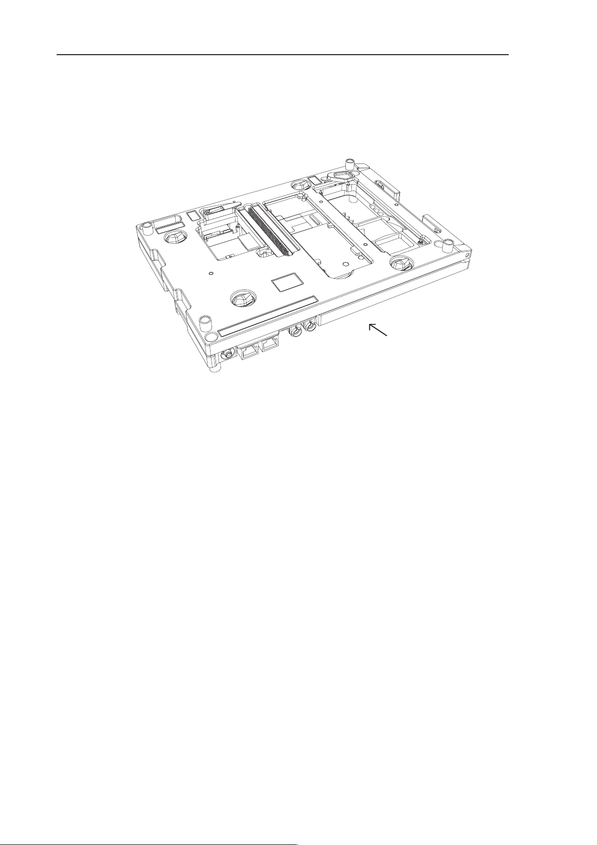
Technical Documentation
Seen from back
Figure 2. MJS–14, the backside
Note: The nominal supply voltage for MJS–14 is +4.0 V.
The supply voltage must not exceed +4.1 V.
Page 6 – 6
Issue1 06/01
Page 7

PAMS
RAE-3
Technical Documentation
User Guide for MJS-14
Warnings:
High Voltage
There is a 1kV high voltage solder point beside left upper corner of PDA display.
Keep the cover always on the dangerous area unless measuring under the PWB.
Power Source
Do not connect negative voltage to Voltage IN –terminals.
Do not connect voltages over 4,2 volts to Voltage IN –terminals.
Flash Mode vs. EPOC Running –mode
If you are using Wintesla service software (for flashing or for testing) do not use
the ”Run EPOC” switch. EPOC software is not allowed to be running during flashing or while software resets are possible (Wintesla connected).
6. Service Tools
External Connections
RF
For external RF connection there is a SMA jack connector. The connection is defined to be made with service cable XRF–1.
Attenuation of the RF connection (without XRF–1 cable) is
appx. 0,2dB for 900MHz band and
0,4dB for 1800MHz band.
System Signals
For system signal connection (Fbus/Mbus) there is a modular 10 socket in the jig.
The socket is compatible also with modular 8 plug.
Preferred cables for system connection are XCS–4 and DAU–9S.
Audio Signals
For audio signals the jig includes also a modular 10 socket. SGND is separated
from general GND although in ADS–1 service cable specificed for use with the jig
those are short–circuited.
Input Terminals
For powering the jig there are two ”banana” sockets. Red one for + terminal and
black for GND terminal.
Issue1 06/01
Page 6 – 7
Page 8

RAE-3
PAMS
6. Service Tools
Detection Switches
There are three switches by which different detections can be done. Switches are
press switch type so the connection is made only while the switch is pressed.
1 S101: Head set detection
2 S102: Hook detection
3 S103: Accessory detection
Starting
Open the cover of the jig and place SIM card and microphone to their places if
needed.
Then place modules of RAE–3 to proper positions: first bl8 / kl8 then in order jc4
(board to board adapter), ul8 (keymat on it if needed) and (keymat under if needed)
dl2 / dl1. Give special attention to connections of board to board connectors, connectors are not specified for continuous removing.
Technical Documentation
Close the cover of the jig.
Turn the jig over.
Connect the flex to UI module.
Place memory card and/or audio holder under its/their covers.
Connect the necessary cables. Jig is ready for use.
Power ON
There are two working modes in jig:
Default State
Entering to default state does not require any user actions. Just turn the power of
the source ON. EPOC software will not run. There is a notification about the state
in PDA display . Wintesla service software can be used with jig, different kind of test
cases will work (PDA display test, MMC test, etc.).
EPOC Running State
”Run EPOC” switch is needed to be pressed down while turning the power ON. The
switch can be released after the SW has started to boot up. EPOC software will
now run.
In Use
Page 6 – 8
For simulation of cover open / cover closed there is a magnet toggle on cover of
the jig. Sticker beside the toggle describes the meaning of positions. The magnetic
force (field strength) is a bit weaker than in Linda communicator.
Issue1 06/01
Page 9

PAMS
RAE-3
Technical Documentation
There are extra GNDs included to jc4 board to board adapter. There is also a special GND pin in middle of the jig.
Finishing
Before turning the main source off press the nail in audio cover to make an interrupt
to processor. This is important especially if you have an active call ON or data
transfer going to/from memory card (or serial flash). After pressing the nail down
turn the source off within 5 seconds (while PDA display is blanked if cover open).
Note: Check whether the SW version of the device under test supports this function (battery removal interrupt).
Signals in Board to Board Adapter JC4
Table 1. Pin List of JC4
Pin Name Description Pin Name Description
6. Service Tools
1 GND 36 LCDDa5
2 DispClk 8,667MHz 37 LCDDa6
3 DISPON 38 LCDDa3
4 FSP 39 LCDDa10
5 LCDDa0 40 LLClk
6 LCD_PWR 41 GND
7 LCDDa11 42 BATT_REM
8 GND 43 SPKP
9 GenSDIO 44 SPKP
10 LCDPWM 45 SPKN
11 GenSClk 2,16MHz/3,25MHz 46 SPKN
12 LCDEN 47 EARN
13 KBLIGHTS 48 EARP
14 LCDRSTX 49 Col0
15 FLVPP 50 Row0
16 VPROG 51 Col9
17 VBB 52 Row9
18 LCDM 53 Col8
19 LCDDa8 54 Col4
20 LCDDa4 55 Col5
21 GND 56 Col6
22 LCDDa7 57 Row6
23 LCDDa9 58 Row8
24 LCDDa2 59 Col3
25 GND 60 Col2
Issue1 06/01
Page 6 – 9
Page 10

RAE-3
PAMS
6. Service Tools
26 LCDDa1 61 Col7
27 VB 62 Col1
28 VB 63 Row5LCDCD
29 VB 64 Row4
30 GND 65 Row3
31 BackPWM 66 –
32 Row5LCDCD 67 Row2
33 Col4 68 Row7
34 GND 69 Row1
35 Col3 70 GND
Technical Documentation
Table 1. (continued) Pin List of JC4
DescriptionNamePinDescriptionNamePin
Page 6 – 10
Issue1 06/01
Page 11

PAMS
RAE-3
Technical Documentation
Flash Prommer FPS-8 (Sales Pack)
The Flash Prommer FPS–8 is used to update the main software of the phone.
Updating is done by first loading the new MCU software from the PC to the
flash prommer, and then loading the new SW from the prommer to the phone.
When updating more than one phone in succession, the MCU software only
needs to be loaded to the prommer once.
The FPS–8 sales pack 0080321 includes:
Item: Service accessory: Type Product code:
1 Flash Prommer FPS–8 0750123
2 AC/DC Adapter FRIWO 0680032
3 D9 – D9 Cable AXS–4
(between PC and FPS–8) 0730090
4 Printer Cable 0730029
5 Installation software for FPS–8
The following additional memories/modules are separately available for FPS–8:
6. Service Tools
– Additional SRAM module (8MB) SF12 0080346 (optional)
– Additional Flash Module (64MB) SF13 0080347 (optional)
Product Code
Flash Prommer FPS–8: 0750123
View of FPS-8
Issue1 06/01
Page 6 – 11
Page 12

RAE-3
PAMS
6. Service Tools
Calibration Unit JBE-2
Calibration Unit JBE–2 is needed for the resistance, current– and voltage calibrations of a RAE–3 Communicator. These calibrations are needed so that the
charging situation would be precise enough.
NOTE:
The JBE–2 is also the voltage source for the BBL–3B service battery. JBE–2 is
the only service equipment which can provide enough current for any service
case. Power output of FPS–8 flash prommer can not provide enough current in
cases of tuning and calling and is ment to be used only for flashing purposes.
Product Code
Calibration Unit JBE–2: 0775290
Technical Documentation
View of JBE–2
Page 6 – 12
Issue1 06/01
Page 13

PAMS
RAE-3
Technical Documentation
User Guide for JBE-2
Service Operations
Needed equipment: a laboratory source, a calibration unit JBE–2, a service battery
BBL–3B and a service cable DAU–9C.
Use the JBE–2 calibration unit as a power source for the phone. It is the only service tool which can provide needed currents in any service case. The JBE–2 is
powered by a laboratory source. Used voltages are 8,0 volts for normal service and
10,5 volts for energy management calibrations. DO NOT connect over 12 volts
voltage to JBE–2.
With Wintesla service software use service cable DAU–9C. Connect the cable
straight from the PC serial port to the system connector of the phone.
Power Management Calibrations
6. Service Tools
Needed equipment: a laboratory source (min 2A out), a calibration unit JBE–2, a
service battery BBL–3B, a service cable DAU–9C and a service cable SCB–3.
Use JBE–2 calibration unit as a source for the phone as described in above section. Put up the whole calibration environment and turn the phone ON before starting the Wintesla service software. Notice that the less the phone consumes current
during calibration the more accurate is the result. So you are advised to do the calibrations while PDA display is off (phone SW reset while cover closed).
Issue1 06/01
Page 6 – 13
Page 14
RAE-3
PAMS
6. Service Tools
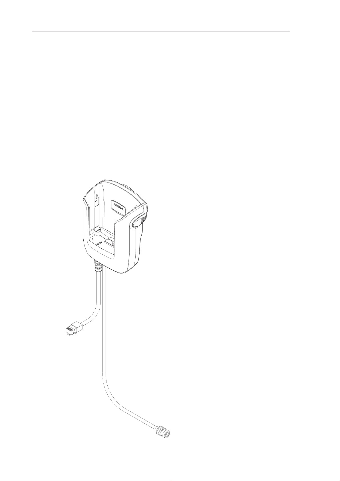
Service Car Kit HCL-1
The Service Car Kit, HCL–1 is used for RF tuning of a RAE–3 communicator.
HCL–1 is modified from CRM–1 car kit. HCL–1 is used as interface between
RAE–3 and service software (Wintesla) while doing RF tuning and power management.
Note 1: Other needed accessories for RF tuning are Modular T adapter and
DAU–9S.
Product Code
Service Car Kit HCL–1: 0770265
View of HCL-1
Technical Documentation
Page 6 – 14
Issue1 06/01
Page 15

PAMS
RAE-3
Technical Documentation
User Guide for HCL-1
Connection to Service SW
A service car kit HCL–1 is used with a Wintesla service software. Needed accessories are Modular–T–adapter and DAU–9S cable. With these accessories the
MBUS is connected straight from the phone to the PC and the necessary level
transformations are executed.. It is also possible to plug the mod8 connector
straight to mod10 socket of FPS–8 prommer and control the phone through it.
Note that it is not allowed to power the service battery from power outputs of FPS–8
while using HCL–1.
Allowed Power Sources
BBL–3B service battery is the one for RF tuning. You will also need the JBE–2 as
power source for the battery. The service battery can also be connected straight
to laboratory power source. Do not connect a voltage higher than 4,2V to service
battery. There is no advanced high voltage protection in the battery so you really
can damage the phone with voltage too high.
6. Service Tools
Note: Do not use normal battery BLL–3 while connected to service SW.
About Tuning
Complete instructions how to make the RF tuning itself can be found from service
manual. Remember that connectors and coaxial cable of HCL–1 will cause attenuation to signal approximately as follows:
Note that values may vary a bit from device to device. If you have the equipment
to define the exact attenuation values for your HCL–1 you are advised to do so.
Note also that the attenuation value is programmed to some tuning equipment with
positive sign and to some with negative sign (depending on the device model /
manufacturer).
900MHz band 0.65dB
1800MHz band 1.05dB
Issue1 06/01
Page 6 – 15
Page 16

RAE-3
PAMS
6. Service Tools
Dummy Service Battery BBL-3B
The Dummy Service Battery BBL–3B (with banana clips) is used in place of the
communicator ’s normal battery during service to supply a controlled operating
voltage from FPS–8 when flashing the communicator.
NOTE: Do not connect BBL–3B straight to a voltage source.
Product Code
Dummy Service Battery BBL–3B: 0770206
View of BBL-3
Technical Documentation
Page 6 – 16
Issue1 06/01
Page 17

PAMS
RAE-3
Technical Documentation
D9-D9 Cable AXS-4
The D9–D9 Cable AXS–4 is used to connect two 9 pin D connectors. e.g. between PC and FPS–8 flash prommer.
Product Code
D9 - D9 Cable AXS-4: 0730090
View of AXS-4
6. Service Tools
Issue1 06/01
Page 6 – 17
Page 18

RAE-3
PAMS
6. Service Tools
MBUS Cable DAU–9C
The MBUS Cable DAU–9C has a phone system connector and D9 female. The
DAU9C is MBUS/FBUS interface cable between the phone and PC RS–232 interface.
Product Code
MBUS Cable DAU–9C: 0730138
View of DAU–9C
Technical Documentation
MBUS Cable DAU-9S
The MBUS Cable DAU–9S has a modular connector, and is used between PC
and the modular T–adapter.
Product Code
MBUS Cable DAU–9S: 0730108
View of DAU-9S
Page 6 – 18
Issue1 06/01
Page 19

PAMS
RAE-3
Technical Documentation
DC Cable SCB–3
The DC Cable SCB–3 is used to connect the Calibration unit, JBE–1 to the
charger connection Vin of the phone when doing the charger calibration service
procedure.
Product Code
DC Cable SCB–3: 0730114
View of SCB–3
6. Service Tools
Service Cable SCH-8
The Service Cable SCH–8 is used between the phone and FPS–8 and it can
used between the phone and modular T–adapter.
Product Code
Service Cable SCH–8: 0730137
View of SCH-8
Issue1 06/01
Page 6 – 19
Page 20
RAE-3
PAMS
6. Service Tools
Technical Documentation
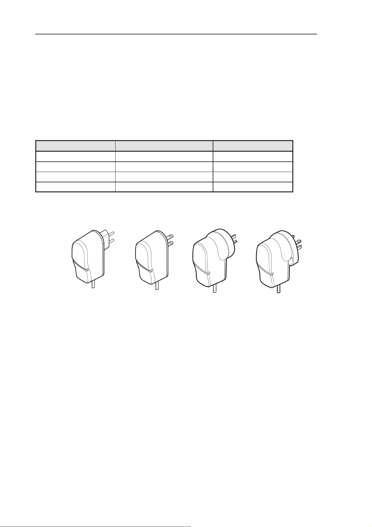
Power ACH-6
There are several variants of ACH–6 DC Power sources available:
Product Code
Name of unit Usage area Material code
ACH–6E Europe 0675084
ACH–6U/J U.S.A / Japan 0675085 / 0675140
ACH–6A Australia 0675086
ACH–6X UK / Hong Kong 0675087
Views of ACH-6
ACH–6E ACH–6X
ACH–6U
ACH–6A
Page 6 – 20
Issue1 06/01
Page 21

PAMS
RAE-3
Technical Documentation
SW Security Device PKD-1
SW security device is a piece of hardware enabling the use of the service software when connected to the parallel (LPT) port of the PC. Without the dongle
present it is not possible to use the service software. Printer or any such device
can be connected to the PC through the dongle if needed.
Caution: Make sure that you have switched off the PC and the printer before
making connections!
Caution: Do not connected the PKD-1 to the serial port. You may damage
your PKD-1!
Product Code
SW Security Device PKD-1: 0750018
View of SW Security Device
6. Service Tools
Modular T–adapter
The modular T–adapter is a suitable branching unit to provide the needed parallel modular connections.
It is used between the Service Car Kit HCL–1 and DAU–9S.
Product Code
Modular T–adapter: 4626134
View of Modular T–adapter
Issue1 06/01
Page 6 – 21
Page 22

RAE-3
PAMS
6. Service Tools
Technical Documentation
This page intentionally left blank.
Page 6 – 22
Issue1 06/01
 Loading...