

Page 1
RAE-3 Repairhints
Customer Care Europe & Africa Version 2.0 Approved
SCCE Training Group 13.03.2002
CONFIDENTIAL
1 (17)
Repairhints
Communicator
9210
RAE-3
© 2002 Nokia Mobile Phones
Checked by:
Customer Care Training Group
Approved by:
SCCE
Page 2
CONFIDENTIAL
2 (17)
RAE-3 Repairhints
Customer Care Europe & Africa Version 2.0 Approved
SCCE Training Group 13.03.2002
General
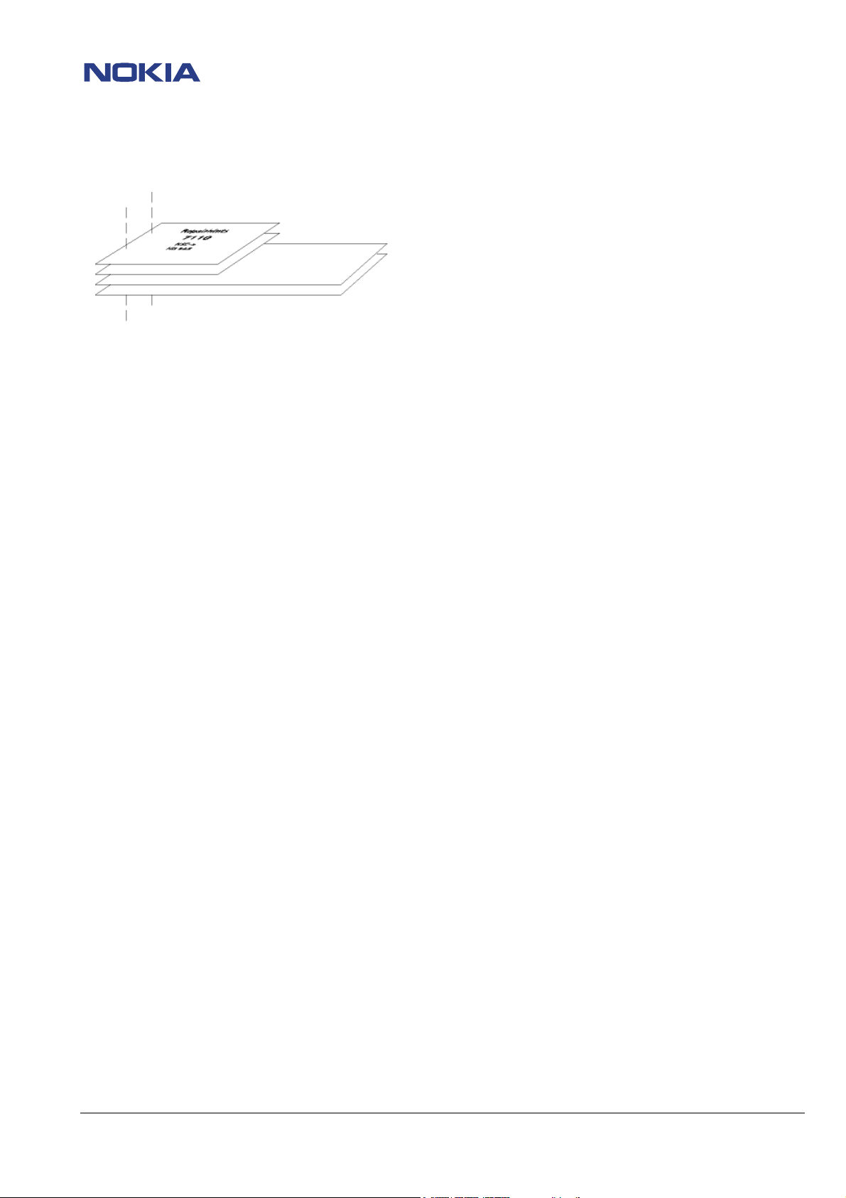
- How to use this document
Place the schematics behind this manual.
Now you are able to follow these specifictions with graphical layouts and it is easier for you to find the components and
measuring points.
- General handling
All screws must be screwed with a torque of 16Ncm. If a higher torque is used, the cover might be damaged.
If it is necessary to make a backup, be sure that the data are ok, otherwise it is possible that the corrupt files are responsible for
the same faults as before reinstalling the backup.
- µBGA components and broken balls
Special attention to µBGA components:
All µBGA´s with the exception of MADLINDA D300 are replaceable and must be renewed after removing. Reflow by hot air fan is
not allowed.
Check soldering points, remove oxidated solderings (broken balls) carefully by enclosing a few new solders before placing new
components. The only allowed way to change µBGA components is to use µBGA rework maschines, approved from NMP (e.g.
ZEVAC/ OK International). Only use recommended Fluxtype and an appropriate amount of it.
- Component charactaristics
Some components contain important data.
Several described steps are only practicable if you are able to reflash/ realign the Communicator 9210 and/ or rewrite IMEI/
SIMlock in certain cases. Please pay attention to separate notes.
- Realign after repair
Characteristics of replacement parts are different.
To prevent additional faults after repair (RX quality, TX power etc.) it is necessary to retune phone values.
© 2002 Nokia Mobile Phones
Checked by:
Customer Care Training Group
Approved by:
SCCE
Page 3
CONFIDENTIAL
3 (17)
RAE-3 Repairhints
Customer Care Europe & Africa Version 2.0 Approved
SCCE Training Group 13.03.2002
IMPORTANT:
This document is intended for use by authorized NOKIA service centers only.
The purpose of this document is to provide some further service information for Communicator 9210.
It contains a lot of collected tips and hints to find failures and repair solutions easily.
It also will give support to the inexperienced technicians.
Saving process time and improving the repair quality is the aim of using this document.
We have built it up based on fault symptoms (listed in "Contents") followed by detailed description for further analysis.
It is to be used additionally to the service manual and other service information like Service bulletins, for that reason it does not
contain any circuit descriptions or schematics.
All measurements are made using following equipment:
Nokia repair SW : WinTesla 6.43
Service SW DLL version : 04.00.00
Flash SW : 4.13
Memory Card Image : All_memory_card_data.SIS for SW 4.13
Nokia Jig : MJS-14
Digital Multimeter : Fluke 73
Oscilloscope : Fluke PM 3380A/B
Spectrum Analyser : Advantest R3162 with an analogue probe
RF-Generator / : CMU 200
GSM Tester
While every endeavour has been made to ensure the accuracy of this document, some errors may exist. If the reader finds any
errors, NOKIA should be notified in writing, using following procedure:
Please state:
Title of the Document + Issue Number/Date of publication.
Page(s) and/or Figure(s) of error.
Please send to: Nokia GmbH
Technical Services E&A
Meesmannstr.103
D-44807 Bochum / Germany
Email: training.sace@nokia.com
Copyright © Nokia Mobile Phones.
This material, including documentation and any related computer programs, is protected by copyright, controlled by Nokia Mobile
Phones. All rights are reserved. Copying, including reproducing, modifying, storing, adapting or translating any or all of this
material requires the prior written consent of Nokia Mobile Phones. This material also contains confidential information, which
may not be disclosed to others without the prior written consent of Nokia Mobile Phones.
© 2002 Nokia Mobile Phones
Checked by:
Customer Care Training Group
Approved by:
SCCE
Page 4
CONFIDENTIAL
4 (17)
RAE-3 Repairhints
Customer Care Europe & Africa Version 2.0 Approved
SCCE Training Group 13.03.2002
Contents
PREFACE
CHAPTER 1 Flash faults 5
PDA does not start/ or CMT backlight is blinking 5
PDA backlight is working but nothing on PDA display 5
CHAPTER 2 D354 Serial Flash faults 6
CHAPTER 3
Emulated EEPROM at D353 flash faulty 6
Product Code and HW version not rewriteable 6
CHAPTER 4 PDA display dark 8
CCFT Lamp and Piezo unit faulty 8
CHAPTER 5
Accessory set 9
CHAPTER 6 MMC not formatable 9
CHAPTER 7 RF faults 9
N505 HAGAR faulty 11
Flowchart N505 HAGAR faulty 13
CHATER 8 Mechanical faults 14
Coaxial cable crushed 14
PDA display change 15
Qwertyflex damaged 15
CHAPTER 9 Assembling-dissassembling notes 16
GENERAL 2
SW update not successful (Set Phone power on) 6
PDA hangs up 6
Error messages appears on PDA display 6
D353 Flash faults 6
IMEI 15*0 / Original Serial Number = 656565656565656 6
Flashing Error message “Can´t Set factory counter” 6
Connection with any kind of accessory not possible 9
No service 9
G800 SHF oscillator faulty 9
Flowchart G800 SHF oscillator faulty 10
A-Cover snaps damaged 16
Flex cover assembling 16
© 2002 Nokia Mobile Phones
Checked by:
Customer Care Training Group
Approved by:
SCCE
Page 5
CONFIDENTIAL
5 (17)
RAE-3 Repairhints
Customer Care Europe & Africa Version 2.0 Approved
SCCE Training Group 13.03.2002
Flash faults
PDA does not start/ or Phone backlight is blinking.
PDA backlight is working but nothing on PDA display.
Note! If the communictator does not boot up after connecting the battery, pay attention to the Phone display. If the
Phone backlight is blinking, refer to the service manual/ Troubleshooting/ Memory Test and/ or Memory troubleshooting,
(See blink code table below) otherwise try to flash the phone first.
- If nothing is on PDA display, interchange the BL8 and UL2 modules with working onces, to find out which is faulty.
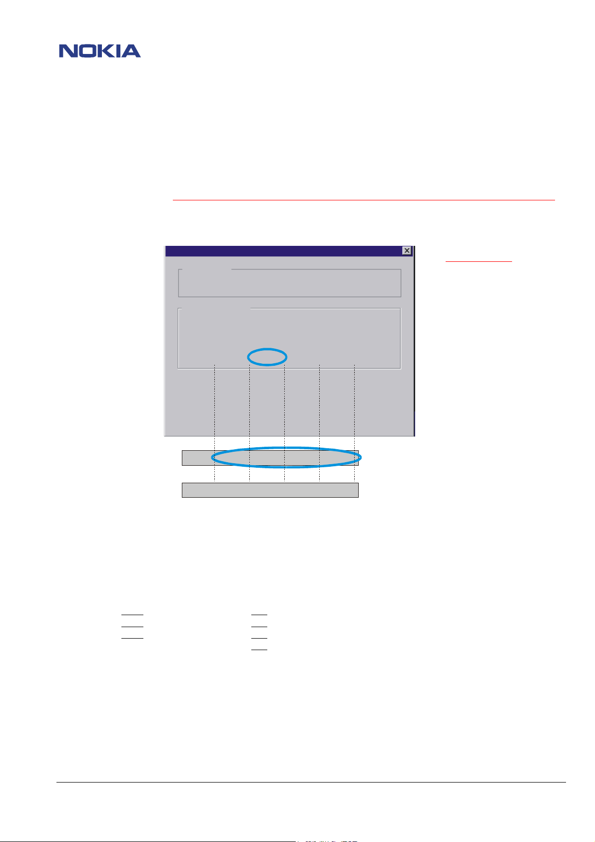
- If the flash update failed, pay attention to the Flash ID´s (See picture below)
Flashing...
Status
Configuration
MCUSW:
The flash manufacturer and device IDs in the existing
algorithm file do not match with the IDs
Blink code table
2* blinks = Flash 0 or 1 or 2 faulty
3* blinks = SDRAM faulty
4* blinks = Serial Flash faulty
The blinks repeating after 2
Corrupt
1)
FLASH 1 (D352) defect
ASIC: 00020210 CSUM: 9688h
Flash ID 0089-8896, 0000-0000, 0089-8896, 0000-0030
seconds. It is not easy to see.
If the flash 0 is faulty, it is
possible that no blinking
sequence is shown on the phone
display and the communicator
does not boot up.
Corrupt
2)
FLASH 0 (D351) defect
Flash ID 0000-0000, 0000-0000, 0000-0000, 0000-0000
3)
OK
Flash ID 0089-8896, 0089-0096, 0089-8896, 0000-0030
D351 XIP 1
FLASH 0
D352 XIP 2
FLASH 1
D353 XIP 3
FLASH 2
D354
Serial FLASH
To 1) - The flash 1 (D352) is faulty. This can be seen at the second flash ID (0000-0000) in the first case.
To 2) - In the most cases D351 is faulty, but also the whole Flash (D351- D354) or D300 MADLINDA could be faulty.
To 3) - In this case all flash IDs and MADLINDA are OK.
- If one of the IDs is 0000-0000, check Vcore = 1.8 VDC and VBB = 2.8 VDC at following components:
D351 Vcore
D352 Vcore
D353 Vcore
D354 --- VBB
at C360/C361 VBB at C353/C354
at C362/C363 VBB at C355/C356
at C366/C370 VBB at C364/C365
at C369
- If Vcore is not ok, check Vcore = 1.8 VDC Pin 4 and Vbatt = 4 VDC at Pin 3 of V105 (VBatt depends on settings of power
supply at the workbench). (Note! VBatt = VB) Also check surrounding components for shorts or disconnections and resolder
or change faulty ones if necessary.
- If VBB is not ok, check VBB = 2.8 VDC at C111. If not ok, check VB = 4VDC at Pin 6 of N102.
- If VB is ok, check N102 and surrounding components for shorts or disconnections and resolder or change the faulty ones if
necessary.
- If all voltages are ok, change the faulty Flash and flash the phone.
- If the fault persists, probably the MADLINDA (D300) is faulty. Up to HW 4.00, the D300 is not changeable because of
underfill.
From HW-ID 4.23 with OSP, the MADLINDA is changeable. (See SB-027)
© 2002 Nokia Mobile Phones
Checked by:
Customer Care Training Group
Approved by:
SCCE
Page 6
CONFIDENTIAL
6 (17)
RAE-3 Repairhints
Customer Care Europe & Africa Version 2.0 Approved
SCCE Training Group 13.03.2002
D354 Serial Flash faults
- SW update not successful (Set Phone power on)
- PDA hangs up
- Error messages appears on PDA display
- If, at the end of flash update, the message “Set phone power on” appears on display (Flash IDs must be correct; see picture at
chapter Flash faults), probably the D354 Serial Flash is faulty and has to be changed.
- If the PDA often hangs up or error messages are appearing on PDA display, try to flash the phone.
- If the same faults persist after flashing, the D354 Serial Flash is faulty and has to be changed.
D353 Flash faults
Emulated EEPROM at D353 Flash faulty
- Product Code and HW version not rewriteable
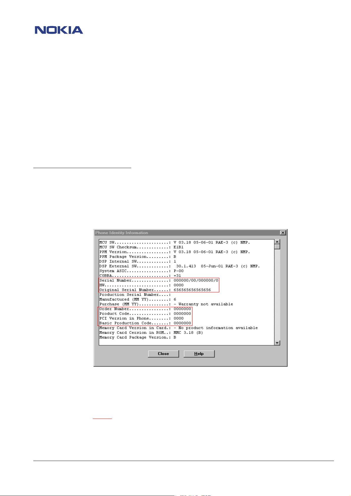
- IMEI 15*0 / Original Serial Number = 656565656565656
- Flashing Error message “Can´t Set factory counter”
- Check which fault has happened using WinTesla menu Testing/ Selftest (e.g. MCU ROM Checksum).
- If one of the EEPROM faults occured, open menu View/ Phone Information and take a look the marked values.(See picture)
Try to flash the communicator with SW 4.13 and promming option Erase Only. Also the memory card has to be updated. If the
MMC is not updated some applications do not working well. (See SB-023)
For a faster MMC-image update it is a good solution to use ext. drive for MMC. (See SB-018)
For Erase Only it is necessary to use the dll version 04.00.00 and the modified RAE3.ini file. (See SB-025)
(Note! Copy the modified RAE3.ini
in the WinTesla/RAE-3 directory. If the RAE3.ini file is not in the right directory the erase only
button in the flash menu is not free to choose.)
© 2002 Nokia Mobile Phones
Checked by:
Customer Care Training Group
Approved by:
SCCE
Page 7

CONFIDENTIAL
7 (17)
RAE-3 Repairhints
Customer Care Europe & Africa Version 2.0 Approved
SCCE Training Group 13.03.2002
Flash menu with modified RAE3.ini file
Choose Erase Only to reset
the flash D353
- After erasing the emulated eeprom, part of the XIP flash D353, the display shows contact service.
- Now flash the phone without marking erase only.
- After flash update set Full Factory and Accessory
(for Accessory see also chapter 4 “Connection with
any kind of accessory not possible”) under menu
software/ Set Factory values (See picture below),
also rewrite product code and HW-ID.
- Rewrite IMEI and SIMlock data if the procedure is permitted to you and tune the phone
- If the erase only procedure not works change the D353 flash.
- After changing the D353 Flash EEPROM, flash the phone. If the SW update was successful, make a full factory and Accessory
set, then rewrite the product code and the HW-ID. After that, rewrite IMEI and SIMlock data.
- If the sw update is not successful, probably D300 MADLINDA is faulty. Up to HW 4.00, the D300 is not changeable because of
underfill.
(Note! Everytime when it is necessary to change the D353 EEPROM or erase the EEPROM, a Full Factory set and
Asseccory set
Note! Rewrite SIMlock and IMEI data by use of NOKIA SECURITY PASSWORD and make a SW-update again, if the
procedure is permitted to you. (See SB–037)
From HW-ID 4.23 with OSP, the MADLINDA is changeable. (See SB-027)
must be done!
© 2002 Nokia Mobile Phones
Checked by:
Customer Care Training Group
Approved by:
SCCE
Page 8

CONFIDENTIAL
8 (17)
RAE-3 Repairhints
Customer Care Europe & Africa Version 2.0 Approved
SCCE Training Group 13.03.2002
PDA display dark
CCFT Lamp and Piezo unit faulty
- If the PDA starts up (startup logo is seen), but the illumation is off, probably the piezo is broken or the backlight circuit is
faulty.
- Check Piezo_in frequency around 135kHz (Vpp = 10 VAC) at L151 and Feedback frequency around 135kHz (Vpp = 2.7 VAC)
at R158. (See picture below)
Piezo_in Feedback
- If Feedback frequency is around 0Hz or Piezo_in frequency is around 100kHz, change CCFT (See SB-014), because the piezo
is broken (see pictures below)
- If changing the CCFT, do not forget to paste the damper (9480703) on the CCFT Lamp and Piezo unit to prevent noises and
damages. (See picture below)
- If the fault persits, probably the UL2 module can also be faulty. (Refer to Service Manual/ Troubleshooting/ BL8 related PDA
UI problems
© 2002 Nokia Mobile Phones
Checked by:
Customer Care Training Group
Approved by:
SCCE
Page 9

CONFIDENTIAL
9 (17)
RAE-3 Repairhints
Customer Care Europe & Africa Version 2.0 Approved
SCCE Training Group 13.03.2002
Connection with any kind of accessory not possible
Accessory set
If the communicator does not connect to any kind of accessory it can be possible that the flash D353 has been changed or the
EEPROM has been erased without making an Accessory Set. Open under WinTesla menu Software/ Set Factory values/ and set
Accessory than try to connect the phone again.
Note! Sometimes it is possible that the connection takes a while.
MMC not formatable
If the communicator hangs up while formating the MMC, it is necessary to flash the phone with newes sw 4.13.
Note! When updating the phone sw, it is also necessary to update the MMC with the newes image. (See SB-023)
For a faster MMC-image update it is a good solution to use ext. drive for MMC. (See SB-018)
RF faults
No service
G800 SHF oscillator faulty
- Check TX I/Q EGSM, Ch: 60 with WinTesla menu Tuning/ TX I/Q. (See picture below)
- If Picture 2 is appearing on spectrum analyser, check following voltages:
- Check Vsynte (VSYN_2/VCC) = 2.8 VDC at R808. If not ok, lift R808 and measure the voltage on the pad to HAGER`s side. If
- If Vsynte (VSYN_2/VCC) is not ok after lifting R808, check N100 CCONT.
- Check VC = 2.2 VDC at R802.
- Check Vchp = 4.7 VDC at C560. If not ok, check VCP = 4.9 VDC at N600 Pin 6. If not ok either, check N100 CCONT.
- If VCP is ok, check N600 voltage regulator and surrounding components for shorts or disconnections and change the faulty
- If VC is not ok, refer to N505 HAGAR faulty.
The G800 SHF Oscillator is working well
The Oscillator is not working
Vsynte is ok, check G800 SHF oscillator and surrounding components for shorts or cold soldering and change or resolder the
faulty ones.
ones. If the surrounding components are ok, change G800 SHF oscillator.
© 2002 Nokia Mobile Phones
Checked by:
Customer Care Training Group
Approved by:
SCCE
Page 10

CONFIDENTIAL
10 (17)
RAE-3 Repairhints
Customer Care Europe & Africa Version 2.0 Approved
SCCE Training Group 13.03.2002
G800 SHF oscillator faulty
RF faults
G800 SHF oscillator
faulty
Use WinTesla to set
phone to EGSM I/Q
tuning mode
(Menu: Tuning/ TX I/Q)
Check TX-Spectrum
(Center 902 MHz)
nOK
Check Vsynte
(VSYN2/VCC) = 2.8 VDC
at R808
OK
Check
VC = 2.2 VDC at
R802
nOK
Check
Vchp = 4.7 VDC
at C560
OK
nOK
OK
OK
G800 SHF
oscillator OK
Lift R808 and
check Vsynte
(VSYN2/VCC) = 2.7 VDC
on Hagarside`s pad
OK
Change G800
SHF oscillator
Check N505
HAGAR
nOK
Check N100 CCONT and
N505 HAGAR
nOK
Check
VCP = 4.9 VDC
at N600,
pin6
OK
Check N600 and surrounding components for
shorts or disconnections, change if necessary
© 2002 Nokia Mobile Phones
nOK
Checked by:
Check N100
CCONT
Customer Care Training Group
Approved by:
SCCE
Page 11

CONFIDENTIAL
11 (17)
RAE-3 Repairhints
Customer Care Europe & Africa Version 2.0 Approved
SCCE Training Group 13.03.2002
N505 HAGAR faulty
- Check VTCXO (VXO) = 2.8 VDC at C553. If not ok, check N100 CCONT.
- Check 26MHz (Vpp = 800mV AC) at R835, frequency deviation ±100Hz (See picture below).
- If not ok, check G830 oscillator circuit.
- Check RFC = 13MHz (Vpp = 800 mVAC) at L800, frequency deviation ±50Hz (See picture below)
- If not ok, check V800 and surrounding components for shorts or disconnections and change the faulty ones, otherwise
probably N505 HAGAR circuit is faulty.
- Check Vsynte (VSYN_2) = 2.8 VDC at C561. If not ok, check N100 CCONT.
- Check VREF_2 = 1.5 VDC at R564. If not ok, check N100 CCONT.
- Check Vchp = 4.7 VDC at C560. If not ok, refer to G800 SHF oscillator faulty
- Check Vrxrf (VRX) = 2.8 VDC (RX active). If not ok, check N100 CCONT.
- Check Reset = 2.8 VDC (in Local Mode) and 2.8V pulse (in Normal Mode / one part (RX/TX) active) at R800 (See picture
below)
© 2002 Nokia Mobile Phones
Checked by:
Customer Care Training Group
Approved by:
SCCE
Page 12

CONFIDENTIAL
12 (17)
RAE-3 Repairhints
Customer Care Europe & Africa Version 2.0 Approved
SCCE Training Group 13.03.2002
- Check Vmod (VTX) = 2.8V at R700. If not ok, check N100 CCONT.
- Check TXC (TX active) at power level 5 (picture 1) and at power level base (picture 2) at R792. If not ok, check N200 COBBA.
- Check SCLK at J501, SDATA at J500 and SENA at J502. (See picture below)
- If one or all three signals are not ok, probably the D300 MADLINDA is faulty.
SCLK
SDATA
SENA
© 2002 Nokia Mobile Phones
Checked by:
Customer Care Training Group
Approved by:
SCCE
Page 13

CONFIDENTIAL
13 (17)
RAE-3 Repairhints
Customer Care Europe & Africa Version 2.0 Approved
SCCE Training Group 13.03.2002
N505 HAGAR faulty
N505 HAGAR faulty
Set phone to local
mode, EGSM, Ch: 60
Check N100 CCONT
nOK
nOK
Check VTCXO (VXO) = 2.8 VDC at C553
OK
Check 26 MHz (Vpp = 800 mVAC) at
R835, frequency deviation <= 100 Hz
OK
Check 13 MHz (Vpp = 800 mVAC) at
R835, frequency deviation <=50 Hz
OK
Check
Vsynthe (VSYN_2)=2.8 VDC at C561,
VREF_2 = 1.5 VDC at R564,
Vxrf(VRX)=2.8VDC (RX active) at C557 and
Vmod (VTX) = 2.8 VDC (TX active)
at R700
nOK
nOK
components for shorts or
Check G830
oscillator circuit
Check V800
and surrounding
disconnections
OK
nOK
Resolder or
change V800
Check G800 SHF oscillator.
Refer to Chapter RF faults/
G800 SHF oscillator faulty
Check D300
MADLINDA
© 2002 Nokia Mobile Phones
nOK
OK
nOK
Check Vchp = 4.7 VDC at C560
OK
Check Reset
=2.8 VDC (Local mode),
=2.8 V pulse (normal mode,
one part RX/TX active) at R800, SCLK at
J501, SDATA at J500,
SENA at J502
OK
Change N505
HAGAR
Checked by:
Customer Care Training Group
Approved by:
SCCE
Page 14

CONFIDENTIAL
14 (17)
RAE-3 Repairhints
Customer Care Europe & Africa Version 2.0 Approved
SCCE Training Group 13.03.2002
Mechanical faults
Coaxial cable crushed
- When assembling the RAE-3 communicator pay attention to the coaxial cable. Be very carefull when closing the back cover.
Make sure that the coaxial cable is routed correctly as shown in figure 3 and 4 below. If the routing is not correct the
coaxial cable can be crushed (Figure 1 and 2 below).
Figure 1
False
Figure 2
Coaxial cable crushed because wrong routed
Figure 3
Correct
Figure 4
Coaxial cable must be routed in center of leave out
© 2002 Nokia Mobile Phones
Checked by:
Customer Care Training Group
Approved by:
SCCE
Page 15

RAE-3 Repairhints
Customer Care Europe & Africa Version 2.0 Approved
SCCE Training Group 13.03.2002
PDA display change
- When the changing of the PDA display is necessary be very carefull when closing the metal clips of the changed PDA display.
You may slip down and scratch the PCB or may lift some components, e.g. L051 (SCLK for display). See pictures below. A good
solution is the use of a small sidecutter for bending the clips down gently.
CONFIDENTIAL
15 (17)
!
I024 Qwertyflex damaged
- When opening the Qwertyflex connector on UI module be very careful because it could be damged.
Do not open the Qwertyflex connector by lifting it from the side. (See picture below)
Not OK
Open the connector by lifting from the middle only. (See picture below)
!
OK
© 2002 Nokia Mobile Phones
Checked by:
Customer Care Training Group
Approved by:
SCCE
Page 16

CONFIDENTIAL
16 (17)
RAE-3 Repairhints
Customer Care Europe & Africa Version 2.0 Approved
SCCE Training Group 13.03.2002
Assembling-dissassembling notes
A-Cover snaps damaged
Be careful when disassembling the A-Cover because it is possible to damage the snaps of the A-Cover. In this case the
A-cover must always be changed. (See pictures below).
Damaged
OK
Flex cover assembling
When assembling the BL8 modul do not press the µBGAs while connecting because the components could be damaged. It is also
important to put the Flex-Cover between Chassis and BL8 modul otherwise a creak tone is to be heard when opening the lid.
False
Correct
© 2002 Nokia Mobile Phones
Checked by:
Customer Care Training Group
Approved by:
SCCE
Page 17

CONFIDENTIAL
17 (17)
RAE-3 Repairhints
Customer Care Europe & Africa Version 2.0 Approved
SCCE Training Group 13.03.2002
Change History
Originator Status Version Date Comment
CC Training
Group
CC Training
Group
CC Training
Group
CC Training
Group
CC Training
Group
Draft 0.1 02.10.2001 First version for the repair group
Approved 1.0 30.10.2001 First approved version
Draft 1.5 01.03.2002 Chapter Flash faults comments changed, information
MMC modified
Draft 1.7 11.03.2002 Comments of Repairgroup added
Approved 2.0 13.03.2002
© 2002 Nokia Mobile Phones
Checked by:
Customer Care Training Group
Approved by:
SCCE
 Loading...