

Page 1
Customer Care Europe, Middel East & Africa NHM-8 / RH-9 Repairhints
SCCE Training Group Version 3.0 Approved
2003 Nokia Mobile Phones
CONFIDENTIAL
Date 27-11-2003
1 (19)
Repair Hints
Service-Level 3 & 4
3510 / 3510i
NHM-8 RH-9
© NMP 2003
Checked by: SCCE
Approved by: Training Group
Page 2
Customer Care Europe, Middel East & Africa NHM-8 / RH-9 Repairhints
SCCE Training Group Version 3.0 Approved
2003 Nokia Mobile Phones
CONFIDENTIAL
Date 27-11-2003
2 (19)
GENERAL
-How to use this document
Put the colored schematics behind this manual.
Now you are able to follow these specifications with graphical layouts and it is easier for you to find the
components and measuring points.
-Component characteristics
Some components contain important data as tuning values or security data, therefore several steps
described are only feasible if you are able to reflash/ realign the phone and/or rewrite IMEI/SIMlock in
certain cases. Please pay attention to separate notes.
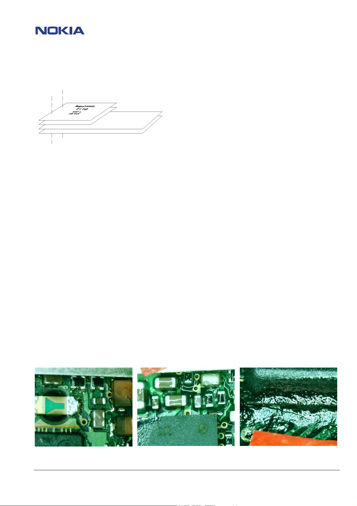
-Broken balls / underfill, µBGAs
All replaceable (not underfilled) µBGA components must be renewed after removing. Reflow with
uncontrolled hot air fan is strictly forbidden! µBGA must only be soldered with NMP approved µBGA rework
machines (e.g. Zevac / OK-Metcal / Martin) to get durable soldering joints.
After removing a µBGA check soldering points, if necessary rework oxidated solderings (broken balls)
carefully by tinplating these areas with few flux and a hot soldering iron. Before placing a new component
remove the tin and clean the PCB, e.g. with help of soder wick and flux cleaner such as “Kontakt LR”.
Use only recommended Fluxtype and an appropriate amount of it – avoid drowning the PCB in flux as this
will result in additional faults!
Also check underfilled parts for broken underfill material below. In this case carefully evaluate possible
repair actions as the phone probably was exposed to strong mechanical stress.
“rework” done with uncontrolled hot air PCB drowned in flux broken underfill of an µBGA part
© NMP 2003
Checked by: SCCE
Approved by: Training Group
Page 3
Customer Care Europe, Middel East & Africa NHM-8 / RH-9 Repairhints
SCCE Training Group Version 3.0 Approved
2003 Nokia Mobile Phones
CONFIDENTIAL
Date 27-11-2003
3 (19)
-PCB handling & cleaning
To avoid damages of PCB and/or components through electrostatic discharging, handle the module in
ESD-suitable cases only. When handling PCBs outside an ESD-bag always wear ESD-bracelets, which must
be connected to earth bonding point. Damage by electrostatic discharge often leads to a module not failing
directly but in a short period of time!
For cleaning use only appropriate materials, do not use scratching or rubbing tools. Useful tools for cleaning
are fluxcleaners such as “Kontakt LR” or “Electrolube FLU” in connection with ionized compressed air.
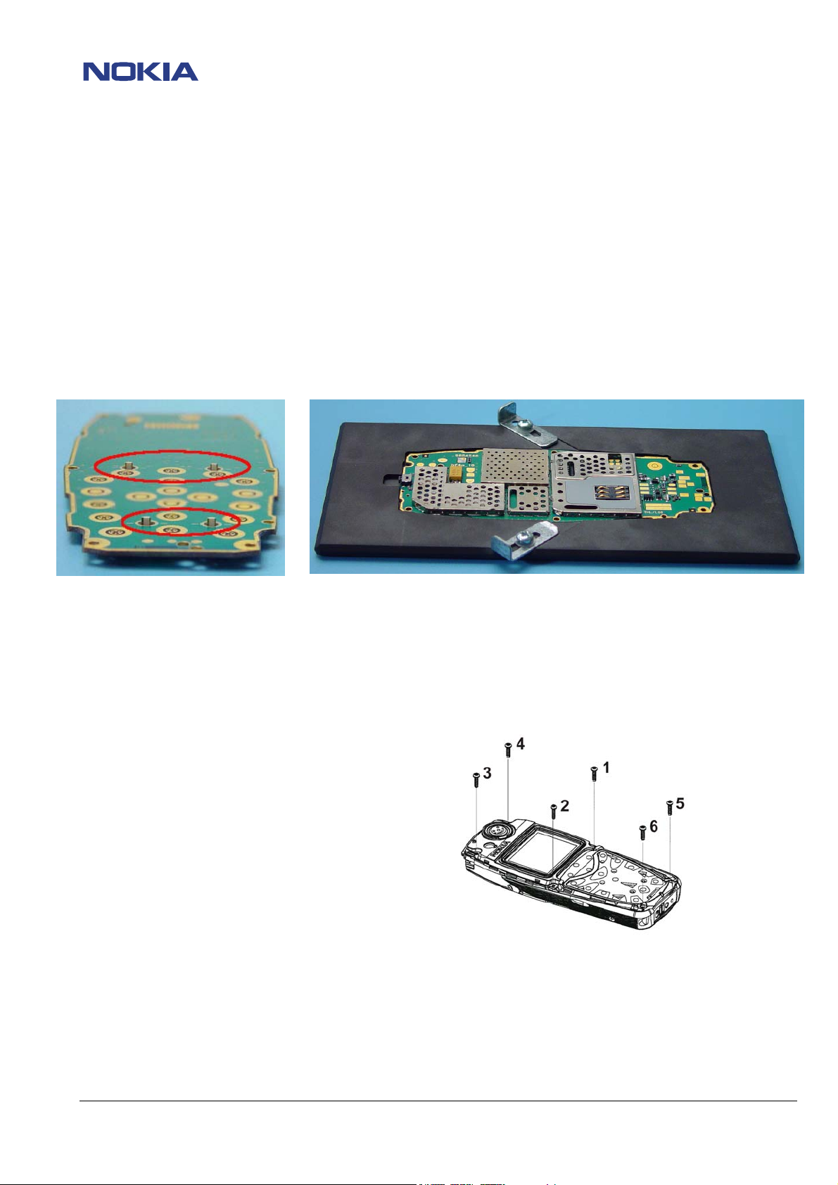
For shield disassembling or any other work on the PCB it is very important to place the PCB into the rework
jig MJS-67 (NMP-code 0770388) to prevent damaging the LEDs – the pads the LEDs are connected with to
the PCB are torn off by applying only little pressure onto the PCB!!!
-Shieldings, screw torques
To avoid RF-problems it is not allowed to reuse any shielding that once has been removed from PCB. Always
use new shieldings after successful repair!
To tighten screws only use a torque screwdriver with a torque adjusted to 28Ncm. Notice tightening order
that is shown in the picture below!
-Realign after repair
Characteristics of replacement parts may vary.
To prevent additional faults after repair (e.g. low standby time, losing network etc.) it is necessary to retune
phone values after repair, but never try to cover up a fault by justing the phone settings!
© NMP 2003
Checked by: SCCE
Approved by: Training Group
Page 4
CONFIDENTIAL
4 (19)
Customer Care Europe, Middel East & Africa NHM-8 / RH-9 Repairhints
SCCE Training Group Version 3.0 Approved
2003 Nokia Mobile Phones
Date 27-11-2003
INTRODUCTION
IMPORTANT:
This document is intended for use by authorized NOKIA service centers only.
The purpose of this document is to provide some further service information for NOKIA 3510/3510i phones.
It contains a lot of collected tips and hints to find faults and repair solutions easily.
It also will give support to inexperienced technicians.
Saving process time and improving the repair quality is the aim of this document.
It is built up based on fault symptoms (listed in "Contents") followed by detailed description for further analysis.
The document is to be used additionally to the service manual and other service information such as Service Bulletins. For that
reason it does not contain any circuit or schematic diagrams.
All measurements are made using following equipment:
Nokia repair SW: Phoenix version 04.13.005
MCU SW: 4.24 for 3510; 3.51 for 3510i
Nokia module jig: MJS - 37
Digital multimeter: Fluke 73
Oscilloscope: Fluke PM 3380A/B
Spectrum Analyzer: Advantest R3131 with an analog probe
RF-Generator / GSM Tester: Rohde & Schwarz CMU 200
While every endeavour has been made to ensure the accuracy of this document, some errors may exist. If the reader finds any
errors, NOKIA should be notified in writing, using the following procedure:
Please state:
title of the document + issue number/date of publication.
page(s) and/or figure(s) in error.
Please send to: Nokia GmbH
Service & Competence Center Europe
Meesmannstr.103
D-44807 Bochum / Germany
Copyright © Nokia Mobile Phones.
This material, including documentation and any related computer programs is protected by copyright, controlled by Nokia Mobile
Phones. All rights are reserved. Copying, including reproducing, modifying, storing, adapting or translating any or all of this
material requires the prior written consent of Nokia Mobile Phones. This material also contains confidential information, which
may not be disclosed to others without the prior written consent of Nokia Mobile Phones.
© NMP 2003
Checked by: SCCE
Approved by: Training Group
Page 5
CONFIDENTIAL
5 (19)
Customer Care Europe, Middel East & Africa NHM-8 / RH-9 Repairhints
SCCE Training Group Version 3.0 Approved
2003 Nokia Mobile Phones
Date 27-11-2003
Contents
PREFACE
CHAPTER 1
CHAPTER 2
CHAPTER 3
CHAPTER 4
CHAPTER 5
CHAPTER 6
CHAPTER 7
CHAPTER 8
CHAPTER 9
General 2
Introduction 4
List of figures 6
CTI calibration 7
Phone does not switch on 8
Phone switches off itself 12
Charging faults 13
SIM card faults 14
User interface faults 15
No service 17
Change history 19
© NMP 2003
Checked by: SCCE
Approved by: Training Group
Page 6
CONFIDENTIAL
6 (19)
Customer Care Europe, Middel East & Africa NHM-8 / RH-9 Repairhints
SCCE Training Group Version 3.0 Approved
2003 Nokia Mobile Phones
Date 27-11-2003
CHAPTER 1: List of figures
Figure Chapter Page
1: 32.768kHz sinewave at C209 3 9
2: 32.768kHz sinewave at C210 3 9
3: 26MHz sinewave at B600 3 9
4: 26MHz reference clock at J425 (measured with spectrum analyzer) 3 10
5: 32.768kHz SLEEPCLK squarewave at J404 3 11
6: 26MHz reference clock at J425 (measured with oscilloscope) 3 11
7: VSIM measured without SIM card at pogo pins of service jig 5 13
8: 26MHz reference clock at J425 (measured with oscilloscope) 8 16
9: TXC at R637 (TX powerlevel 10) 8 16
10: TXP at C646 8 16
11: TXIQ at R610 / R611 8 16
12: RFBusData at J610 8 16
13: RFBusClock at J608 8 16
14: RFBusEnable at J609 8 16
15: VPCTRL_G at R713 8 17
16: VTX_B_G at R717 8 17
17: VTXLO_G at R716 8 17
© NMP 2003
Checked by: SCCE
Approved by: Training Group
Page 7

CONFIDENTIAL
7 (19)
Customer Care Europe, Middel East & Africa NHM-8 / RH-9 Repairhints
SCCE Training Group Version 3.0 Approved
2003 Nokia Mobile Phones
Date 27-11-2003
CHAPTER 2: CTI calibration
- This step is necessary to calibrate the AD converter for the cover detection.
- Use any active cover for calibration you have available (no service-tool deliverable).
Measure the value of CTI resistor of your active cover between "Ground" and "Control" (see picture below).
Supply
Ground
Control
- Enter this value into the calibration window (CTI resistor).
- Press "calibrate", then press “write”.
© NMP 2003
Checked by: SCCE
Approved by: Training Group
Page 8

CONFIDENTIAL
8 (19)
Customer Care Europe, Middel East & Africa NHM-8 / RH-9 Repairhints
SCCE Training Group Version 3.0 Approved
2003 Nokia Mobile Phones
Date 27-11-2003
CHAPTER 3: Phone does not switch on
Change B200,
also check C210 for cold or
broken solderings,
probably D200 faulty.
nOK
Check / change
S300, R317.
nOK
Check lines fo r shorts to
ground or interruption,
probably UEM D200 faulty.
nOK
Change Mjoelner.
nOK
UEM D200 faulty in all
probability.
nOK
UPP D400 fault y in all
probability.
nOK
Phone does not
switch on
Check if
current consumption is around
18mA
(in repair jig with 8VDC).
nOK
Check 32.768kHz
(see figure 1)
at C210.
OK
Check that
PWRONX decreases to 0V if
powe rswitch is pre ssed.
OK
Check
VIO 1.8VDC at C207 ,
VCORE1.5VDC at C208,
VANA 2.8VDC at C206,
and VR3 2.8VDC at C227 rise to
their intended values.
OK
Check 26 MHz
(see figure 5)
at J425.
OK
Check PURX 1.8VDC at J402,
sleepclock squarewave at J404.
OK
Change flash
D450 and flash again.
Flashing ok?
OK
Rewrite IMEI and
SIM lock data !
OK
nOK
OK
Try to make SW-update.
SW-update successful?
nOK
If
failuremessage from
prommer is "wrong
manufactor/device ID"
update prommerbox
and flash again.
Flashing ok?
OK
Flashing ok! Realign
and test the phone!
OK
Flashing ok! Realign
and test the phone!
© NMP 2003
Checked by: SCCE
Approved by: Training Group
Page 9

CONFIDENTIAL
9 (19)
Customer Care Europe, Middel East & Africa NHM-8 / RH-9 Repairhints
SCCE Training Group Version 3.0 Approved
2003 Nokia Mobile Phones
Date 27-11-2003
I010 (X101)
- Check mechanical appearance of battery connector; change part if it is bent, soiled or corroded.
S300
- Check mechanical appearance of powerswitch; change part if necessary.
- Check voltage at S300: 4 VDC in case the switch is not pressed.
If voltage is not measureable or too low check especially R317 and C310.
- If switch is pressed, voltage at R317 (measure to UEM side) must decrease to 0V; otherwise you have to
exchange the switch
B200
- Check DC-voltages at C209 (0.59V) and C210 (0.42V). If voltages are not ok check lines for shorts to ground.
It also is possible that UEM D200 is defect.
- Change the crystal B200 if DC-voltages at C209 / C210 are ok but no 32.768kHz sinewave signal is measurable
(see picture below).
Note that this signal is always measurable in MJS-37 jig even though the phone is switched off.
Figure 1: 32.768kHz at C209
N600 (Mjoelner)
- Check VR3 2.8VDC at C620.
- Check 26MHz sinewave signal at B600 (picture below). If it is not measurable check DC-voltage at both sides of
crystal B600 that normally is 2VDC. In case that DC-voltage is missing Mjoelner N600 has to be changed. If
voltage at crystal is ok but no 26MHz sinewave is measurable crystal B600 has to be exchanged.
Figure 3: 26MHz at B600
Figure 2: 32.768kHz at C210
© NMP 2003
Checked by: SCCE
Approved by: Training Group
Page 10

CONFIDENTIAL
10 (19)
Customer Care Europe, Middel East & Africa NHM-8 / RH-9 Repairhints
SCCE Training Group Version 3.0 Approved
2003 Nokia Mobile Phones
Date 27-11-2003
- Check signal of 26MHz reference clock oscillator at J425 (see figure below).
If signal is not measurable (at least as a short pulse) but 26MHz sinewave at B600 is ok you have to exchange
Mjoelner N600.
Figure 4: 26MHz at J425
D450 (Flash)
- Check if current consumption remains on 18mA (in repair jig supplied with 8VDC). This indicates that Flash D450
probably is empty. Try to make SW-update. If any failure message appears during flashing, try SW-update a second
time. A failure message C101 or C102 from prommer box indicates that D200 or D400 is defect in all probability. In
case of failure message C586 the problem may be solved by changing the Flash D450.
Note that in this case you have to rewrite IMEI and SIMlock data. Furthermore you have to
run all RX/TX-tunings, energy management calibration and CTI calibration!!!
D200 (UEM)
- check 32.768kHz sinewave at C209/210
- check VANA 2.8VDC at C206
- check VIO 1.8VDC at C207
- check VCORE 1.5VDC at C208
- check VR3 2.8VDC at C227 (at least a short pulse!)
- check PURX 1.8VDC at J403
- if one value is not measurable or too low, check the corresponding line for short circuit to ground. If resistance of line
seems to be ok UEM D200 is faulty in all probability - swap the phone as UEM is not changeable.
If all above mentioned signals are ok try to flash the phone. A failure message C101 or C102 from prommer box
indicates that D200 or D400 is defect in all probability. In case of failure message C586 the problem may be solved by
changing the Flash D450.
© NMP 2003
Checked by: SCCE
Approved by: Training Group
Page 11

CONFIDENTIAL
11 (19)
Customer Care Europe, Middel East & Africa NHM-8 / RH-9 Repairhints
SCCE Training Group Version 3.0 Approved
2003 Nokia Mobile Phones
Date 27-11-2003
D400 (UPP)
Check following signals:
- VIO 1.8VDC at C400
- VCORE 1.5VDC at C451
- SLEEPCLK 32kHz at J404
- 26MHz system clock at J425
- PURX 1.8VDC at J403
- If one of the above mentioned signals is not measurable probably UEM is faulty; swap the phone as UEM is not
changeable. The only exception is a missing system clock – in this case check B600 and N600.
- If signals are okay try to flash the phone A failure message C101 or C102 from prommer box indicates that D200 or
D400 is defect in all probability. In case of failure message C586 the problem may be solved by changing the
Flash D450.
Figure 5: Sleepclock at J404
Figure 6: 26MHz at J425
N700 (Poweramplifier)
- It has been observed that in several cases the power amplifer N700 was responsible for the mentioned fault. A good
indicator for this is the current consumption: if N700 is defect the current often rises up to more than 0.5A directly
after connecting the phone to the power supply. To ensure that the PA is responsible, remove L703. If the current is ok
now, the PA is defect in all probability.
© NMP 2003
Checked by: SCCE
Approved by: Training Group
Page 12

CONFIDENTIAL
12 (19)
Customer Care Europe, Middel East & Africa NHM-8 / RH-9 Repairhints
SCCE Training Group Version 3.0 Approved
2003 Nokia Mobile Phones
Date 27-11-2003
CHAPTER 4: Phone switches itself off
First of all you should check whether this symptom is not the result of an insufficient charged battery. In case of doubt retest the
phone with a new or well charged battery. If this does not solve the problem, check the following points:
I 010 (battery connector)
- Check mechanical appearance of battery connector, especially check spring contacts if bent, soiled or corroded. Also
ensure that contact pads on the PCB are clean; if necessary remove dirt with help of alcohol but never use any
scratching or rubbing tools!
D200 (UEM)
- In case the phone switches off itself constantly after 32 seconds first you should check whether this symtom is caused
by missing security data: rewrite IMEI and SIMlock data. In case that fault persists, this usually is an internal fault of
UEM D200. As this part is underfilled it is not possible to repair the fault.
N700 (Poweramplifier)
- It has been observed that also the power amplifier can cause the above described fault. Often the phone switches off
itself if you try to tune the upper TX power level as here the current consumption becomes too high. Remember to
realign the power level after reworking the PA!
© NMP 2003
Checked by: SCCE
Approved by: Training Group
Page 13

CONFIDENTIAL
13 (19)
Customer Care Europe, Middel East & Africa NHM-8 / RH-9 Repairhints
SCCE Training Group Version 3.0 Approved
2003 Nokia Mobile Phones
Date 27-11-2003
CHAPTER 5: Charging Faults
battery size failed
battery temperature failed
Check BSI-line fo r shorts
to GND, check C747, L710
or change X101.
Check BTEMP-line for shorts to
GND, check C746, L711 fo r cold or
broken soldering or
change X101.
In case the charging of battery fails, first thing to do is to run energy management calibration.
Note that calibration only works with JBV-1, MJF-16 docking station adapter and 12VDC power supply.
In case charging does not work permanently or charging is possible from time to time only, especially check spring contacts of
bottom connector I007 and battery connector I010 if bent, soiled or corroded. Also make sure that contact pads for the
connectors on the PCB are clean. If necessary clean the PCB with an appropriate amount of alcohol. Do not use any scratching
or rubbing tools!
Whenever a part has been changed in the charging circuit, you have to run energy management calibration to ensure a proper
function of the phone!
I007 / I010
- Check mechanical appearance of battery connector and bottom connector; change parts if spring contacts are bent,
soiled or corroded. Also ensure that contact pads for both connectors on the PCB are clean.
F100
- Check resistance of fuse; must be zero Ohm.
V100
- Check that V100 does not cause a short circuit to ground. Resistance of VCHAR-line to ground normally is 2.6kOhm.
Furthermore ensure that V100 is well soldered, otherwise UEM might be damaged!
D200
- If all steps above are checked, probably UEM (D200) is faulty. Swap the phone because UEM is underfilled and
therefore not changeable.
Charging not
possible
Run energy
manageme nt
calibration.
nOK
batte ry voltage failed
UEM D200 f aulty
in all probab ility.
OK
Try to char ge after
calibration.
charge volt age failed
check / change X101.
Check F100, L100, V100 and C100
for cold or br oken solde ring. Or
shorts to GND, if failure pe rsists
UEM is faulty .
charge current failed
Check res istance of R200
(0.22 Ohm).
UEM D200 is faulty.
© NMP 2003
Checked by: SCCE
Approved by: Training Group
Page 14

CONFIDENTIAL
14 (19)
Customer Care Europe, Middel East & Africa NHM-8 / RH-9 Repairhints
SCCE Training Group Version 3.0 Approved
2003 Nokia Mobile Phones
Date 27-11-2003
CHAPTER 6: SIM card faults
X387
- If “Insert SIM card” appears on LCD, first of all check mechanical appearance of SIM card reader X387.
- You have to change SIM reader if contact springs are bent, soiled or corroded.
R386/D200/D400
- If fault persists and mechanical appearance of SIM reader seems to be ok, check with oscilloscope if SIM lines at
SIM reader pins 1-4 are pulses to 1.8V / 3V as shown in the chart below (Phone switched on without SIM card).
Signals are slightly different between pins 1-4 but the amplitude always is 1.8V / 3V.
Figure 7: VSIM
In case that the above mentioned signal is not measurable at one or more SIM lines, check SIM lines for shorts to ground.
Resistance of SIM data- and VSIM line normally is > 200kOhm, resistance of SIM reset- and SIM clock line normally is
about 4.5MOhm.
If resistance of any line is not ok check parts the SIM lines consists of (R386, C203, C381, C390).
In case resistance of all lines is ok but fault persists, EMI-filter R386 may have internal interruption.
Change part and retest the phone. It also is possible that UEM D200 or UPP D400 are responsible for this fault.
Swap the phone because these components are underfilled and not changeable.
Display message
"Insert SIM card"
Check at
SIM reader pin 1-4
if pulsed to
1.8V/3Vpp.
nok
Check SIM lines fo r
shorts to GND.
nok
Check / change EMI-filter
R386, C203, C381
and C390.
Check SIM card if dir ty, check
ok
ok
mechanical appearance of SIM reader
and SIM cover, change parts if
necessary.
Check / change R386.
If this does not solve the problem
D200/D400 are probably f aulty.
Swap phone.
© NMP 2003
Checked by: SCCE
Approved by: Training Group
Page 15

CONFIDENTIAL
15 (19)
Customer Care Europe, Middel East & Africa NHM-8 / RH-9 Repairhints
SCCE Training Group Version 3.0 Approved
2003 Nokia Mobile Phones
Date 27-11-2003
CHAPTER 7: User Interface Faults
Display faulty
- Change display module I004 to check if it is responsible for the fault.
- If the fault persists check VIO 1.8VDC at C303, VFLASH1 2.8VDC at C304 and
10.65VDC at pin 8 from display modul, before measuring carefully remove display metal frame.
After removing metal frame measure at the point shown in the right picture below, marked by the red arrow.
- If the display still does not work but the voltages are measurable, probably UPP (D400) is faulty.
Swap the phone as UPP is not changeable.
Measure 10.65 VDC at the red arrow
© NMP 2003
Checked by: SCCE
Approved by: Training Group
Page 16

CONFIDENTIAL
16 (19)
Customer Care Europe, Middel East & Africa NHM-8 / RH-9 Repairhints
SCCE Training Group Version 3.0 Approved
2003 Nokia Mobile Phones
Date 27-11-2003
Keypad problems
Whenever there are problems with the keypad, first of all check that the keypad area of the PWB is not dirty. If necessary clean
the PWB with an appropiate amount of alcohol, but never use any scratching or rubbing tools!
Display assembly I004
In most of all keypad problems the root-cause are damaged key domes. As the dome sheet including the key domes is glued onto
the display assembly and not available as single spare part, it is necessary to exchange the whole display assembly I004.
Keypad problems after changing flash D450
Since short time a new hardware of 3510i is available. One renewal that has been made is the keypad appearance, which has
been changed from so-called “cake-pattern” (old) to the normal appearance of keys (new), see picture.
In connection with the new layout it is (among other data) essential to write back the hardware ID after the flash circuit D450
has been exchanged.
If reading the original hardware ID was not possible because of a defect D450, for all new PWBs (version ey1a_06) the HW-ID
must be higher than 2000, for PWBs of version ey1a_04 the HW-ID must be lower than 2000!
If you forget to write back the HW-ID with phones of PWB version ey1a_06, only the keys 1,2,3,5 and 6 will work, all others
won´t work!
© NMP 2003
Checked by: SCCE
Approved by: Training Group
Page 17

CONFIDENTIAL
17 (19)
Customer Care Europe, Middel East & Africa NHM-8 / RH-9 Repairhints
SCCE Training Group Version 3.0 Approved
2003 Nokia Mobile Phones
Date 27-11-2003
CHAPTER 8: No Service
In case that it is not possible to establish a call with your phone, the first thing to do is to perform all RF-calibrations to find out
more about the fault. If for example TX-power is not measurable or too low, check transmitters signal path beginning with e.g.
TXIQ signals at R610/611. If the receiver does not work properly, check receivers signal path beginning e.g. with the incoming RFsignal at diplexer Z700. If both RX and TX do not work check parts which are needed for both signal pathes (e.g. supply voltages,
oscillators B600, G600 or Mjoelner N600).
No or too low TX-power
Mjoelner N600
If you suppose Mjoelner N600 to be responsible for the TX-fault, first check the following signals before exchanging N600.
Set phone with Phoenix to local mode and activate TX-burstmode Ch.37 (Ch.700 for GSM1800).
- Check supply voltages VR1A 4.7VDC at both sides of R603, VR2 2.8VDC at C612, VR3 2.8VDC at C618, VR5 2.8VDC at C614,
VR6 2.8VDC at C610, VR7 2.8VDC at C624, VIO 1.8VDC at C621 and VREF01 1.35VDC at C626.
- Check 26MHz reference clock at J425. Unfortunately it is not possible to check the signal of the SHF-oscillator directly, but
you can check the control voltage at C641: if this voltage is outside its normal range (1.2VDC up to 3.2VDC) this indicates
that the oscillator probably is faulty or the control loop is open. Further more check ResetX_Mjoelner at R604, which
normally is 1.8VDC.
Figure 8: 26MHz at J425
- Check with an oscilloscope TXC at R637 (0.7Vpp – 1.8Vpp depending on TX-powerlevel), TXP 1.8Vpp at C646 and TX/IQsignals at both sides of C627/628:
Figure 9: TXC at R637
- Check with an oscilloscope RFBusData at J610, RFBusClk at J608 and RFBusEnable at J609:
Figure 12: RFBusData at J610
If all these signals are ok but no TX-signal is measurable at L606 (L604 in GSM1800), Mjoelner N600 is faulty in all probability.
Figure 10: TXP at C646 Figure 11: TXIQ at R610/611
Figure 13: RFBusClock at J608 Figure 14: RFBusEnable at J609
© NMP 2003
Checked by: SCCE
Approved by: Training Group
Page 18

CONFIDENTIAL
18 (19)
Customer Care Europe, Middel East & Africa NHM-8 / RH-9 Repairhints
SCCE Training Group Version 3.0 Approved
2003 Nokia Mobile Phones
Date 27-11-2003
Poweramplifier N700
In case that power amplifier N700 seems to be responsible for the TX-fault, first check the following voltages and signals that are
necessary for a proper working amplifier before exchanging N700.
Set phone with Phoenix to local mode and activate TX-burstmode Ch.37 (Ch.700 for GSM1800).
- Check VBATT 4VDC at both sides of L703
- Check VPCTRL_G 0.8Vpp – 1.4Vpp dependent on TX powerlevel at R713 (GSM 1800: VPCTRL_P at R708)
Figure 15: VPCTRL_G at R713
- Check VTX_B_G 2.7Vpp at R717 (GSM 1800: VTX_B_P at R719)
Figure 16: VTX_B_G at R717
- Check VTXLO_G 2.7Vpp squarewave in GSM 900 TX powerlevel 5 & 6 at R716. If TX powerlevel is 7 or lower signal at R716 is
2.7VDC. (For GSM 1800 switching between high/low mode is not available)
Figure 17: VTXLO_G at R716
If the signal at the amplifier´s input at R714 (GSM 1800: R711) and the above mentioned signals are ok but still there is no or too
low TX power at the amplifier´s output, it is necessary to exchange N700. Remember to perform RF-calibrations after having
exchanged the power amplifier.
© NMP 2003
Checked by: SCCE
Approved by: Training Group
Page 19

CONFIDENTIAL
19 (19)
Customer Care Europe, Middel East & Africa NHM-8 / RH-9 Repairhints
SCCE Training Group Version 3.0 Approved
2003 Nokia Mobile Phones
Date 27-11-2003
Chapter 9: Change History
Originator Status Version Date Comment
TS Training
Group
Draft 0.1 04/09/2002 First Draft version
TS Training
Group
TS Training
Group
TS Training
Group
TS Training
Group
Approved 1.0 17/10/2002 First approved release
Draft 1.2 04-03-2003 Update to 3510i
Approved 2.0 10-03-2003 Updated version approved
Approved 3.0 27-11-2003 Update: keypad problems with 3510i
© NMP 2003
Checked by: SCCE
Approved by: Training Group
 Loading...