

Page 1

Programmes After Market Services
NPW-1 Series Transceivers
Service T ools
Issue 1 10/01 ãNokia Corporation
Page 2

NPW-1
Service Tools PAMS Technical Documentation
Table of Contents
Page No
Module Jig (MJS-18, 0770299) ...................................................................................5
Product Code............................................................................................................. 5
POS Dongle (FLS-4, 0774263) ...................................................................................6
Product Code............................................................................................................. 6
FPS-8 Flash Prommer for heavy flash (0080321, sales pack) .....................................7
Product Code............................................................................................................. 7
FPS-8C Flash Prommer for heavy parallel flash (0080396) .......................................8
Product Code............................................................................................................. 8
Docking Station (JBV-1, 0770298) and Docking Station Adapter (MJF-2, 0770300) 9
Product Code............................................................................................................. 9
Galvanic Contact (GAC-1, 0770301) ........................................................................10
Product Code........................................................................................................... 10
Coupler (CPL-1, 0770287) ........................................................................................11
Product Code........................................................................................................... 11
Audio box (JBA-8, 0770320) ....................................................................................12
Product Code........................................................................................................... 12
Audio Cable (ADS-4, 0730222) ................................................................................13
Product Code........................................................................................................... 13
Mbus/Fbus Cable (XCS-4, 0730178) ........................................................................14
Product Code........................................................................................................... 14
Flash Adapter (FLA-13, 0770297).......................................................................... 15
Product Code........................................................................................................... 15
Soldering Jig (MJS-27, 0775287) ..............................................................................16
Product Code........................................................................................................... 16
Printer Cable (AXP-8, 073F000) ...............................................................................17
Product Code........................................................................................................... 17
D9-D9 Cable (AXS-4, 0730090) ...............................................................................18
Product Code........................................................................................................... 18
Audio Cable (ADS-3, 0730197) ................................................................................19
Product Code........................................................................................................... 19
DC Cable (SCB-3, 0730114) .....................................................................................20
Product Code........................................................................................................... 20
MBUS Cable (DAU-9S, 0730108) ............................................................................21
Product Code........................................................................................................... 21
Power Cable (PCS-1, 0730012) .................................................................................22
Product Code........................................................................................................... 22
RF Cable (XRF-1, 0730085) .....................................................................................23
Product Code........................................................................................................... 23
Service Cable (XCS-4, 0730178) ..............................................................................24
Product Code........................................................................................................... 24
Power Pack, (DDC-10, 0670405) ..............................................................................25
SW Security Device (PKD-1, 0750018) ....................................................................26
Product Code........................................................................................................... 26
Flashing and Testing Setups ........................................................................................ 27
POS flash (FLS-4, 0081482 - Setup 1) ......................................................................27
Product Code........................................................................................................... 27
Flashing, testing and tuning with covers on (Setups 2a, 2b and 2c) ..........................28
Page 2 ãNokia Corporation Issue 1 10/01
Page 3

NPW-1
PAMS Technical Documentation Service Tools
Service tool setup 2a ............................................................................................... 29
Service tool setup 2b............................................................................................... 29
Service tool setup 2c ............................................................................................... 30
Flashing and testing with covers off (Setup 3) ..........................................................31
Parallel Flash (Setup 4) ..............................................................................................32
Service tool setup 4................................................................................................. 32
Warranty and user data transfer (Setup 5) .................................................................33
Service tool setup 5:................................................................................................ 33
Page No
Issue 1 10/01 ãNokia Corporation Page 3
Page 4

NPW-1
Service Tools PAMS Technical Documentation
List of Figures
Page No
Fig 1 View of Module Jig MJS-18 ......................................................................................5
Fig 2 View of POS Dongle, FLS-4......................................................................................6
Fig 3 View of Flash Prommer for heavy flash, FPS-8.........................................................7
Fig 4 View of Flash Prommer for heavy parallel flashing ..................................................8
Fig 5 View of Docking Station, JBV-1................................................................................9
Fig 6 Docking station and docking station adapter..............................................................9
Fig 7 View of Galvanic Contact, GAC-1 ............................................................................10
Fig 8 View of Coupler, CPL-1.............................................................................................11
Fig 9 View of Audio Box, JBA-8........................................................................................12
Fig 10 View of Audio Cable, ADS-4).................................................................................13
Fig 11 View of Mbus/Fbus Cable, XCS-4...........................................................................14
Fig 12 View of Flash Adapter, FLA-13...............................................................................15
Fig 13 View of Soldering Jig, MJS-27................................................................................16
Fig 14 View of Printer Cable, AXP-8..................................................................................17
Fig 15 View of D9-D9 Cable AXS-4 ..................................................................................18
Fig 16 View of Audio Cable ADS-3 ..................................................................................19
Fig 17 View of DC Cable SCB-3 ........................................................................................20
Fig 18 View of MBUS Cable DAU-9S ...............................................................................21
Fig 19 View of Power Cable PCS-1....................................................................................22
Fig 20 View of RF Cable XRF-1.........................................................................................23
Fig 21 View of Service Cable XMS-3.................................................................................24
Fig 22 DDC-10 Power Pack ................................................................................................25
Fig 23 View of Power Pack, DDC-10 .................................................................................25
Fig 24 View of SW Security Device PKD-1.......................................................................26
Fig 25 View of POS flash....................................................................................................27
Fig 26 Service tool setup 2a.................................................................................................29
Fig 27 Service tool setup 2b ................................................................................................29
Fig 28 Service tool setup 2c.................................................................................................30
Fig 29 Service tool setup 3 ..................................................................................................31
Fig 30 Service tool setup 4 ..................................................................................................32
Fig 31 Service tool setup 5 .................................................................................................33
Page 4 ãNokia Corporation Issue 1 10/01
Page 5

NPW-1
PAMS Technical Documentation Service Tools
Module Jig (MJS-18, 0770299)
This jig allows phone PWB -level service and troubleshooting.
Electric circuits have to be protected against over-voltage and over-current.
Product Code
MJS-18: 0770299
Figure 1: View of Module Jig MJS-18
Table 1: Spare parts for MJS-18
Item Description Type Designation Code Supplier
1 Fuse T2A 5x20
2 Test prope GSS-19-3.9-G 540A007 IDI
3 Test probe GKS079 301050A1300 54OY001 INGUN
4 RF probe HRC2901-021002 978F005 SMK
5 System Connector
Assembly
5460043 Molex
Issue 1 10/01 ãNokia Corporation Page 5
Page 6
NPW-1
Service Tools PAMS Technical Documentation
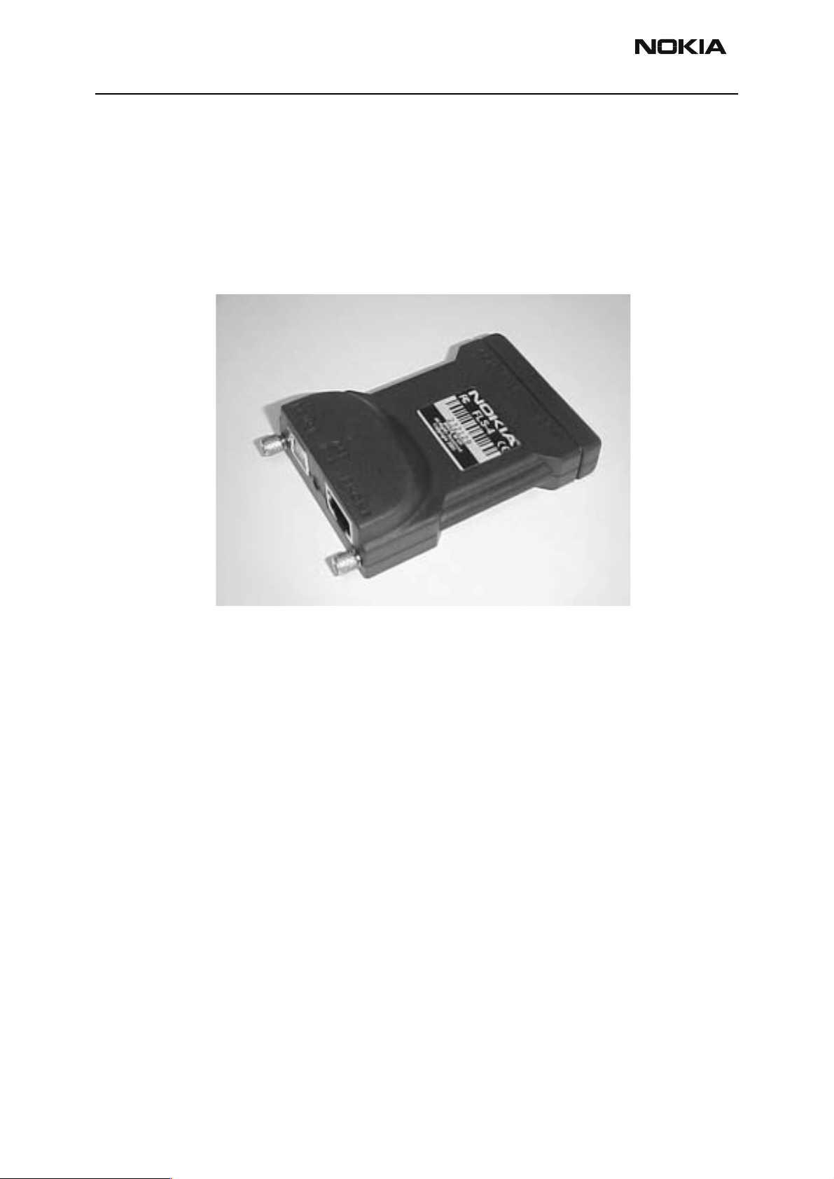
POS Dongle (FLS-4, 0774263)
The POS flash concept needs the Flash Adapter and cable between the phone and the
FLS-4.
Product Code
FLS-4: 0774263
Figure 2: View of POS Dongle, FLS-4
Page 6 ãNokia Corporation Issue 1 10/01
Page 7
NPW-1
PAMS Technical Documentation Service Tools
FPS-8 Flash Prommer for heavy flash (0080321, sales pack)
The FPS-8 flash prommer is used for heavy flashing.
Product Code
FPS-8: 0080321
Figure 3: View of Flash Prommer for heavy flash, FPS-8
Issue 1 10/01 ãNokia Corporation Page 7
Page 8
NPW-1
Service Tools PAMS Technical Documentation
FPS-8C Flash Prommer for heavy parallel flash (0080396)
The FPS-8C Flash Prommer is used for heavy parallel flashing.
Product Code
FPS-8C: 0080396
Figure 4: View of Flash Prommer for heavy parallel flashing
Page 8 ãNokia Corporation Issue 1 10/01
Page 9
NPW-1
PAMS Technical Documentation Service Tools
Docking Station (JBV-1, 0770298) and Docking Station Adapter (MJF-2,
0770300)
The Docking Station and Docking Station Adapter are needed for Mbus, Fbus, RF and
Audio connections. This setup allows a connection be tween flash prommers. When the
audio box is connected, it has to be connected to the phone’s audio connector. The Docking Station can be powered by the FPS-8 or an external power supply.
Product Code
JBV-1: 0770298
MJF-2: 0770300
Spare parts for MJF-2 test pin: 540Y207 (test probe code)
Figure 5: View of Docking Station, JBV-1
Figure 6: Docking station and docking station adapter
Issue 1 10/01 ãNokia Corporation Page 9
Page 10
NPW-1
Service Tools PAMS Technical Documentation
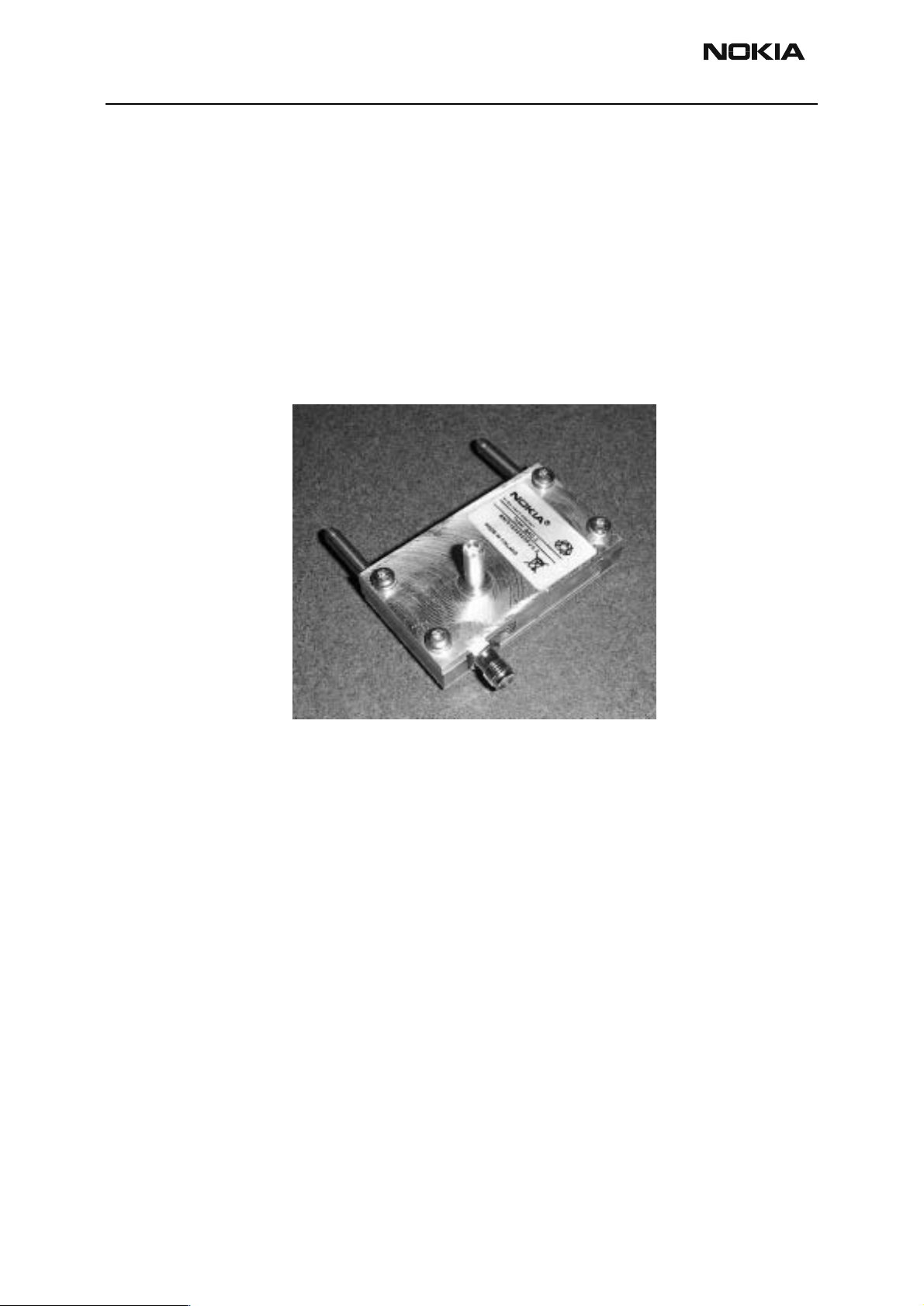
Galvanic Contact (GAC-1, 0770301)
The GAC-1 adapter is needed for the RF conne ction. The GAC-1 adapter makes galvanic
connections to assembled handset RF-switches p ossible. Via this ad apter, the handset is
connected to the RF measuring and test equipment.
Note: Unnecessary usage of the handset’s RF-switch must be avoided.
Product Code
GAC-1: 0770301
Figure 7: View of Galvan ic Contact, GAC-1
Page 10 ãNokia Corporation Issue 1 10/01
Page 11
NPW-1
PAMS Technical Documentation Service Tools
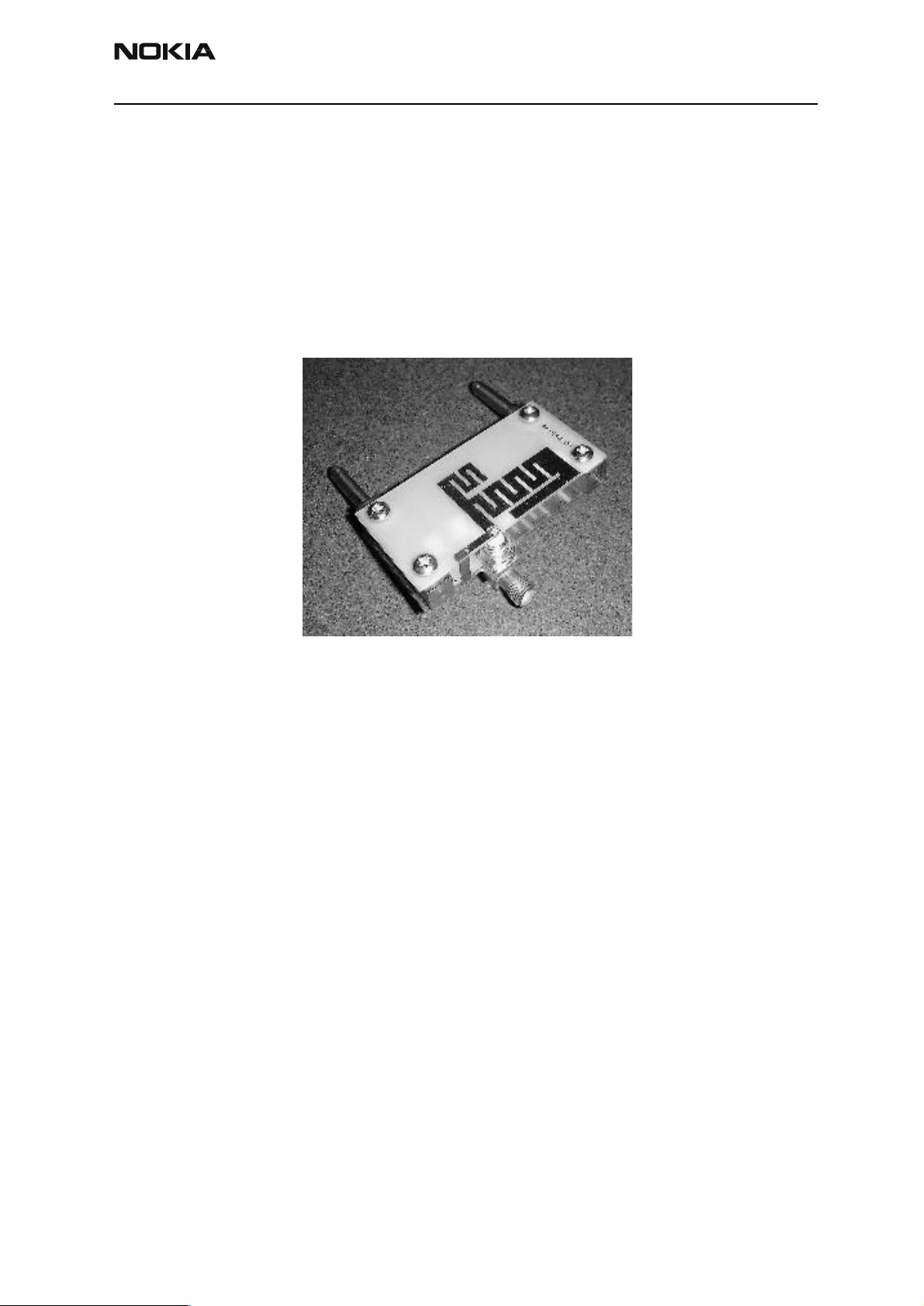
Coupler (CPL-1, 0 770287)
The Coupler has been developed for antennas’ go/no go testing.
Note: Tuning is not allowed with the CPL-1.
Product Code
CPL-1: 0770287
Figure 8: View of Coupler, CPL-1
Issue 1 10/01 ãNokia Corporation Page 11
Page 12

NPW-1
Service Tools PAMS Technical Documentation
Audio box (JBA-8, 0770320)
The Audio Box is needed for audio connections. The box must support DCT4 Janette
audios.
Service Audio box JBA-8. The Service Audio box provides an interconnection between the
phone’s system connector (XEAR, XMIC) through a fixed audio cable and Audio tester
with a BNC-BNC coax.The cConnection to a PC can be made with the servic e battery,
through a DAU-9 cable. The Service Audio Box JBA-8 is used for service purposes.
Product Code
JBA-8: 0770320
Figure 9: View of Audio Box, JBA-8
Page 12 ãNokia Corporation Issue 1 10/01
Page 13

NPW-1
PAMS Technical Documentation Service Tools
Audio Cable (ADS-4, 0730222)
The Service Cable between the phone and the Ser vice Audio Box.
Product Code
ADS-4: 0730222
Figure 10: View of Audio Cable, ADS-4)
Issue 1 10/01 ãNokia Corporation Page 13
Page 14

NPW-1
Service Tools PAMS Technical Documentation
Mbus/Fbus Cable (XCS-4, 0730178)
The Mbus/Fbus cable connects the phone a nd the flash box.
Product Code
XCS-4: 0730178
Figure 11: View of Mbus/Fbus Cable, XCS-4
Page 14 ãNokia Corporation Issue 1 10/01
Page 15

NPW-1
PAMS Technical Documentation Service Tools
Flash Adapter (FLA-13, 0770297)
The Flash Adapter allows a continuous maximum power supply for the phone from an
external power supply: the ACP-8. The service battery allows Mbus/Fbus connections.
The Flash Adapter must be protected against over-voltage, ove r-current and cross-connections. The Flash Adapter has to be regulated.
Note: The Flash Adapter is not to be used for handset testing, and is only meant for
flashing.
Product Code
FLA-13: 0770297
Spare parts for FLA-13 test pin: 540Y207 (test probe)
Figure 12: View of Flash Adapter, FLA-13
Issue 1 10/01 ãNokia Corporation Page 15
Page 16

NPW-1
Service Tools PAMS Technical Documentation
Soldering Jig (MJS-27, 0775287)
The Soldering Jig is used to hold the PWB during repair and troubleshooting.
Product Code
MJS-27: 0775287
Figure 13: View of Soldering Jig, MJS-27
Page 16 ãNokia Corporation Issue 1 10/01
Page 17

NPW-1
PAMS Technical Documentation Service Tools
Printer Cable (AXP-8, 073F000)
The Parallel Printer Cable connects the parallel connector of the PC and the "PARALLEL
INPUT" of FPS-8 or FPS-8C.
Product Code
AXP-8: 073F000
Figure 14: View of Printer Cable, AXP-8
Issue 1 10/01 ãNokia Corporation Page 17
Page 18

NPW-1
Service Tools PAMS Technical Documentation
D9-D9 Cable (AXS-4, 0730090)
The D9-D9 cable AXS-4 is used to connect two 9 pin D connectors, for example, between
a PC and a TDF-4 security box.
Product Code
D9-D9 Cable AXS-4: 0730090
Figure 15: View of D9-D9 Cable AXS-4
Page 18 ãNokia Corporation Issue 1 10/01
Page 19

NPW-1
PAMS Technical Documentation Service Tools
Audio Cable (ADS-3, 0730197)
The Audio Cable connects to the Audio box JBA-6.
Product Code
Audio Cable ADS-3: 0730197
Figure 16: View of Audio Cable ADS-3
Issue 1 10/01 ãNokia Corporation Page 19
Page 20

NPW-1
Service Tools PAMS Technical Documentation
DC Cable (SCB-3, 0730114)
The DC Cable SCB-3 is used to connect the Service Battery to the charger connection Vin
of the phone when doing the charger calibrat ion service procedure.
Product Code
DC Cable SCB-3: 0730114
Figure 17: View of DC Cable SCB-3
Page 20 ãNokia Corporation Issue 1 10/01
Page 21

NPW-1
PAMS Technical Documentation Service Tools
MBUS Cable (DAU-9S, 0730108)
The MBUS Cable DAU-9S has a modular connector, and is used with the service Audio
Box JBA-4 or a modular T-adapter.
Product Code
MBUS Cable DAU-9S: 0730108
Figure 18: View of M BU S Cable DAU-9S
Issue 1 10/01 ãNokia Corporation Page 21
Page 22

NPW-1
Service Tools PAMS Technical Documentation
Power Cable (PCS-1, 0 730012)
The Power Cable PCS-1 is used to connect the JBT-1 and JBS-19 module jigs to an external power supply. It can also be used with FPS-4.
Product Code
Power Cable PCS-1: 0730012
Figure 19: View of Power Cable PCS-1
Page 22 ãNokia Corporation Issue 1 10/01
Page 23

NPW-1
PAMS Technical Documentation Service Tools
RF Cable (XRF-1, 0730085)
The XRF-1 RF cable is used to connect the MJS-9 Test frame to the RF measurement
equipment.
Product Code
RF Cable XRF-1: 0730085
Figure 20: View of RF Cable XR F-1
Issue 1 10/01 ãNokia Corporation Page 23
Page 24

NPW-1
Service Tools PAMS Technical Documentation
Service Cable (XCS-4, 0730178)
The XCS-4 Service Cable is a modular cable for flashing DCT4 products.
Product Code
Service Cable XCS-4: 0703178
Figure 21: View of Service Cable XMS-3
Page 24 ãNokia Corporation Issue 1 10/01
Page 25

NPW-1
PAMS Technical Documentation Service Tools
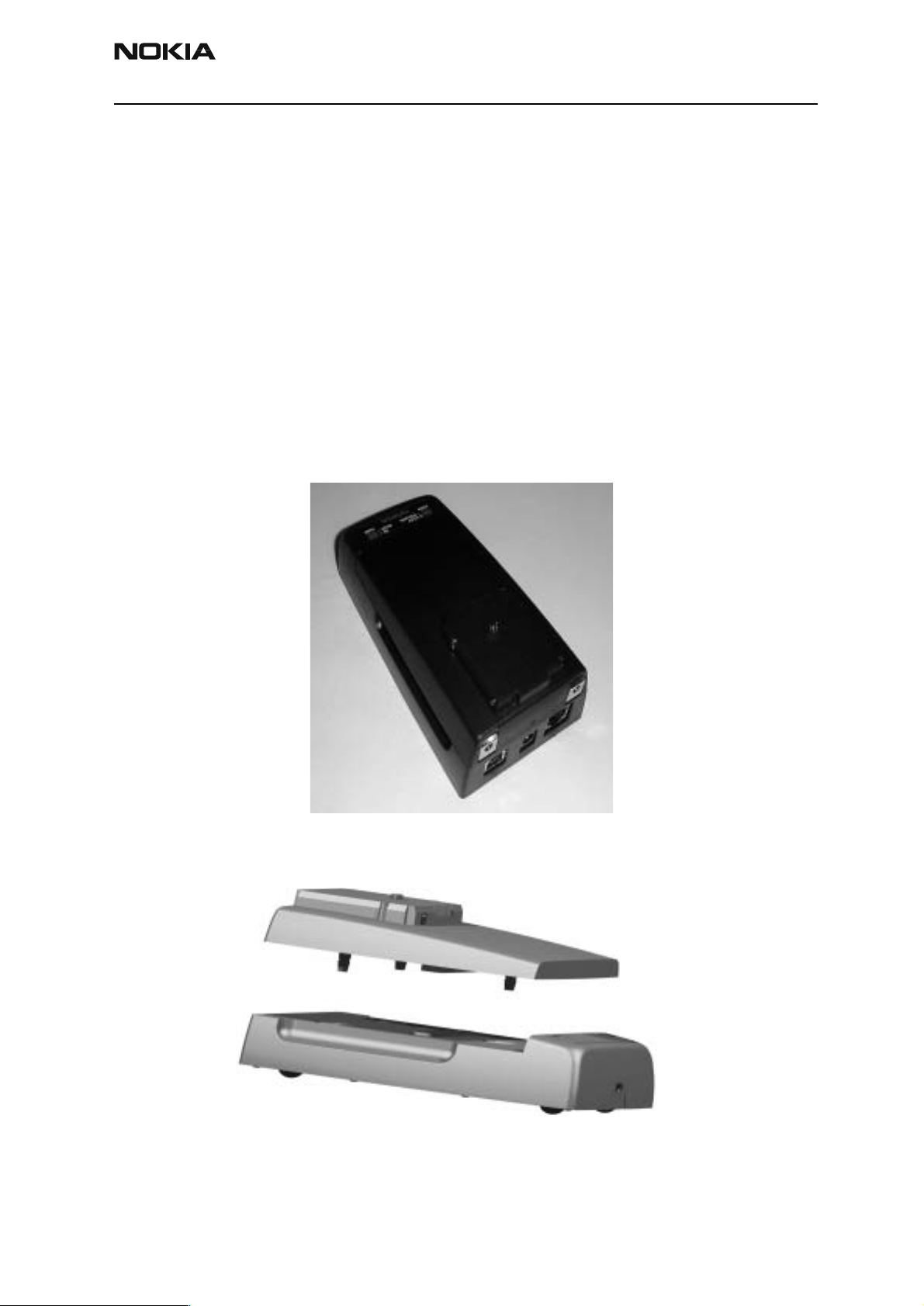
Power Pack, (DDC-10, 0670405)
The Power Pack is designed to provide the phone with power via F LA-13. The phone’s
own battery can be used in DDC-10.
Note: DDC-10 allows battery charging. When it is used as a charger, the power pack
need to be disconnected.
Note: When DDC-10 is used as a Power Pack, battery charging is not allowed!
Figure 22: DDC-10 Power Pack
Figure 23: View of Power Pack, DDC-10
Note: Do not plug in cable in charger receptacle.
Issue 1 10/01 ãNokia Corporation Page 25
Page 26

NPW-1
Service Tools PAMS Technical Documentation
SW Security Device (PKD-1, 0750018)
The SW security device is a piece of har dware enabling the use of the service softwa re
when connected to the para llel (LPT) port of a PC. Without the dongle present it is not
possible to use the service software. A printer or any such device can be connected to the
PC through the dongle, if needed.
Caution: Make sure that you have switched off the PC and the printer before mak-
ing connections.
Caution: Do not connect the PKD-1 to the serial port. You may damage your PKD-
1.
Product Code
SW Security Device PKD-1: 0750018
Figure 24: View of SW Security Device PKD-1
Page 26 ãNokia Corporation Issue 1 10/01
Page 27

NPW-1
PAMS Technical Documentation Service Tools
Flashing and Testing Setups
POS flash (FLS-4, 0081482 - Setup 1)
This setup is made for the Point-of-Sale but it can also be used in service centers. The
purpose of this is to make flashing as easy as possible at the POS’s and prevent the
unnecessary handset flow to service.
Product Code
POS Dongle, FLS-4 (US): 0081482
POS Dongle, FLS-4 (APAC): 0081481
POS Dongle, FLS-4 (E/A): 0081483
Figure 25: View of POS flash
Table 2: Service tool setup 1
Item Name Type
11 Service SW CD-ROM for NPW-1 8406941
12. POS dongle (US) FLS-4 (US) 0081482
POS dongle (APAC) FLS-4 (APAC) 0081481
POS dongle (E/A) FLS-4 (E/A) 0081483
13. Service cable XCS-1 0730218
18. Travel charger ACP-8U 0675196
19. Flash Adapter FLA-13 0770297
25 Power Pack DDC-10 0670405
Code
Issue 1 10/01 ãNokia Corporation Page 27
Page 28

NPW-1
Service Tools PAMS Technical Documentation
Flashing, testing and tuning with covers on (Setup s 2a, 2b and 2c)
Tightened performance specifica tions require more precise equipment and methods for
testing and alignment. Manual tuning cannot provide accurate results for NPW-1 products, which means that this task has to be automated.
These setups are intended to be used with eit her Phoenix o r Darium SW. With the Phoenix SW it is possible to do manual testing and automated tuning. With Darium, it is possible to do automated testing and tuning.
Table 3: Service tools setup 2a, 2b and 2c
ITEM NAME TYPE CODE
1. Docking Station JBV-1 0770298
2. Docking Station Adapter MJF-2 0770300
3. Service cable XCS-4 0730178
4. DC cable PCS-1 0730012
5. DC cable SCB-3 0730114
6. Flash loading adapter FPS-8 0080321
7. D9–D9 Cable AXS-4 (included in FPS-8 sales pack) 0730090
8. Printer cable IEEE1284 Parallel Cable, AXP-8 (included in
FPS-8C sales pack)
9. AC charger ACF-8 (included i n FPS-8 sales pack) 0680032
10. Software protection key PKD-1 0750018
11. Service SW CD-ROM for NPW-
1
14. RF cable XRF-1 07300 85
16. Audio box JBA-8 0770320
20. RF probe GAC-1 0770301
21. RF coupler CPL-1 0770287
22 Security Box TDS-6 0770181
24. Audio Cable ADS-4 0730222
073F000
8406941
Tuning and call testing need an external power supply.
Page 28 ãNokia Corporation Issue 1 10/01
Page 29

NPW-1
PAMS Technical Documentation Service Tools
Service tool setup 2a
This setup is for testing and tuning (RF testing and tuning is not possible) and EM
(Energy Management) calibration.
When EM calibration is being done, the JBV-1 needs to by powered by 12V from an
external power supply. EM calibration can also be done by connecting the JBV-1 to a PC
using a DAU-9S cable.
Figure 26: Service tool setup 2a
Service tool setup 2b
With this setup, RF testing and tuning is possible.
Figure 27: Service tool setup 2b
Issue 1 10/01 ãNokia Corporation Page 29
Page 30

NPW-1
Service Tools PAMS Technical Documentation
Service tool setup 2c
This setup makes antenna go/no go testing possible.
Figure 28: Service t oo l setup 2c
Page 30 ãNokia Corporation Issue 1 10/01
Page 31

NPW-1
PAMS Technical Documentation Service Tools
Flashing and testing with covers off (Setup 3)
Table 4: Service Tool setup 3
ITEM NAME TYPE CODE
3. Service cable XCS-4 0730178
4. DC cable PCS-1 0 730012
6. Flash loading adapter FPS-8 0080321
7. D9–D9 Cable AXS-4, (included in FPS-8C sales pack 0730090
8. Printer cable, IEEE1284 Parallel
Cable
9. AC charger ACF-8 (included in FPS-8 sales pack) 0680032
10. Software protection key PKD-1 0750018
11. Service SW CD-ROM for NPW-1 8406941
15. Module Jig MJS-18 0770299
16. Audio box JBA-8 0770320
Figure 29: Service tool setup 3
AXP-8 (included in FPS-8C sales pack) 073F000
Issue 1 10/01 ãNokia Corporation Page 31
Page 32

NPW-1
Service Tools PAMS Technical Documentation
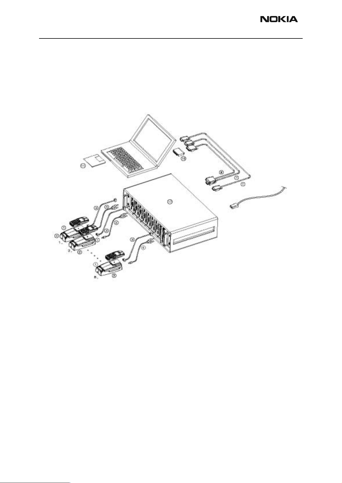
Parallel Flash (Setup 4)
The Parallel Flash setup allows flashing eight individual handsets at the same time. This
requires the PC to fulfil the following requirements: the PC has to have two physical
serial ports (COM1 and COM2).
Service tool setup 4
Table 5: Service tool setup 4
ITEM NAME TYPE CODE
1. Docking Station JBV-1 0770298
2. Docking Station Adapter MJF-2 0770300
3. Service cable XCS-4 0730178
4. DC cable PCS-1 0730012
7. 2 x D9–D9 Cable AXS-4, (included in FPS-8C sales pack) 0730090
8. Printer cable, IEEE1284 Parallel Cable AXP-8 (included in FPS-8C sales pack) 073F000
10. Software protection key PKD-1 0750018
11. Service SW CD-ROM 8406941
17. FPS-8C FPS-8C 0080396
Figure 30: Service tool setup 4
Page 32 ãNokia Corporation Issue 1 10/01
Page 33

NPW-1
PAMS Technical Documentation Service Tools
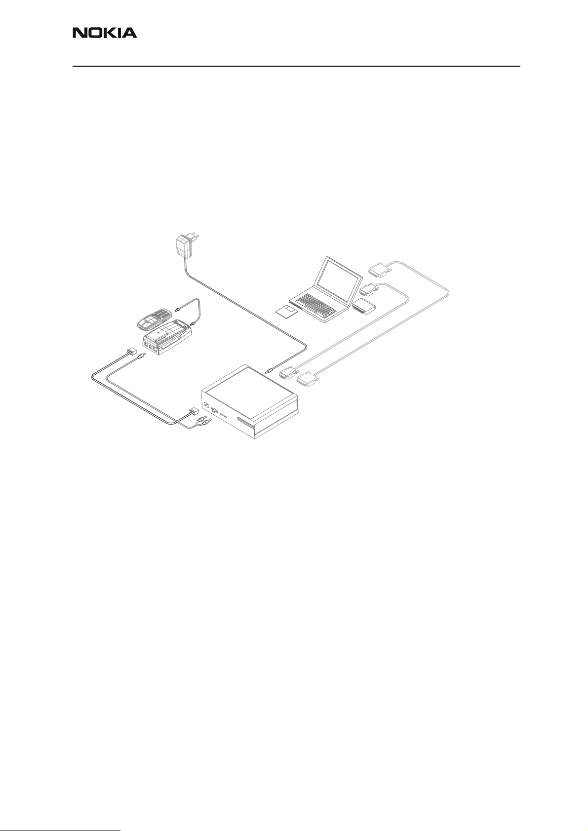
Warranty and user data transfer (Setup 5)
This setup is for Warranty Data and User Data transfer from phone to phone.
Service tool setup 5:
Table 6: Service tool setup 5
ITEM NAME TYPE CODE
3. Service cable XCS-4 0 730178
18. Travel charger ACP-8U (two) 0675196
19. Flash Adap ter FLA-13 (two) 0770297
Figure 31: Service tool setup 5
Issue 1 10/01 ãNokia Corporation Page 33
Page 34

NPW-1
Service Tools PAMS Technical Documentation
This page intentionally left blank.
Page 34 ãNokia Corporation Issue 1 10/01
 Loading...