

Page 1

Nokia Customer Care
RH-37 Series Transceivers
5 - Disassembly Instructions
Issue 1 07/04 2004 Nokia Corporation Page 1
Company Confidential
Page 2

RH-37
5 - Disassembly Instructions Nokia Customer Care
[This page left intentionally blank]
Page 2 Nokia Corporation Issue 1 07/04
Page 3

RH-37
Nokia Customer Care 5 - Disassembly Instructions
Table of Contents
Page No
Disassembly Instructions....................................................................................................................... 5
General requirements ..........................................................................................................................5
Detailed disassembly instructions ...................................................................................................6
Dome Sheet Placement....................................................................................................................... 11
Cleaning ................................................................................................................................................11
Placing the dome sheet to the light guide ..................................................................................11
Placing the light guide assembly onto the PWB .......................................................................13
Issue 1 07/04 Nokia Corporation Page 3
Page 4

RH-37
5 - Disassembly Instructions Nokia Customer Care
[This page left intentionally blank]
Page 4 Nokia Corporation Issue 1 07/04
Page 5

RH-37
Nokia Customer Care 5 - Disassembly Instructions
Disassembly Instructions
General requirements
Use the correct ESD protection before handling the RH-37 product.
Use gloves to handle the RH-37 product.
Required tools:
• torx 6 screwdriver, for disassembly
• torx 6 torque-driver, set to 28Ncm torque for reassembly
• slotted screwdriver
• tweezers
• SS-42 camera removal tool
• SRT-6 opening tool
•DC-plug
Note: When shielding lids are removed from the shielding frames of the PWB, new lids must be used
in order to close the shielding properly. It is not allowed to re-use the removed ones.
Issue 1 07/04 Nokia Corporation Page 5
Page 6

RH-37
5 - Disassembly Instructions Nokia Customer Care
Detailed disassembly instructions
Needed tools for disassembly.
Press the C-Cover Lock before pulling the C-Cover. Protect the Camera Window with a plastic film.
Protect the Window with a plastic film.
Lift the topside of the A-Cover and then remove it carefully.
Also protect the inner side of A-Cover with a plastic film.
Page 6 Nokia Corporation Issue 1 07/04
Page 7

RH-37
Nokia Customer Care 5 - Disassembly Instructions
Remove Keymat.
6
5
®
Unscrew the six Torx Plus
reverse order and a Torx Plus
28Ncm has to be used.
size 6 screws. For assembly, the
2
1
®
driver with a torque of
3
4
Separate the Modules from B-Cover. Open the LCD Connector with SRT-6 carefully.
Use SRT-6 to separate the LCD-Module from UI-Shield. Protect the LCD-Module with a plastic film.
Issue 1 07/04 Nokia Corporation Page 7
Page 8
RH-37
5 - Disassembly Instructions Nokia Customer Care
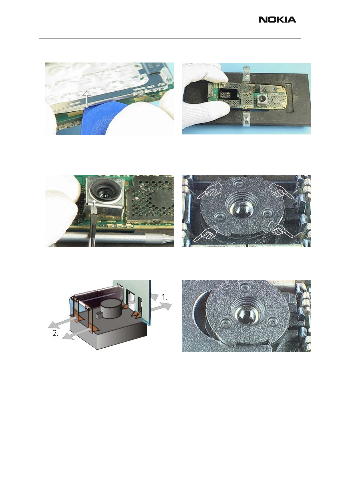
When changing the Light Guide Assy use SRT-6 as a lever.
Keep in mind that Dome Sheet is glued to the Engine
Module.
Use a slotted screwdriver as a lever to open the Camera
Shield.
Put the Engine Module into the Soldering Jig.
Camera Module is attached with four double snaps into its
guidance.
Place the removal tool as shown in the picture and unlock
the snaps on both sides. Note releasing order.
Remove the Camera Module with the removal tool as
shown in the picture.
Page 8 Nokia Corporation Issue 1 07/04
Page 9

RH-37
Nokia Customer Care 5 - Disassembly Instructions
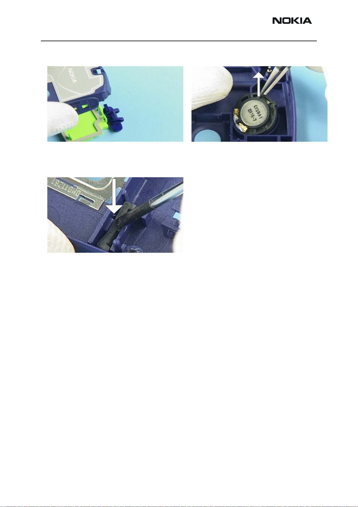
All Gel Grips are attached to the B-Cover with hooks.
Slide the Gel Grip as shown in the picture to unlock the
hooks.
Use the DC-Plug to remove the DC-Connector. Tweezers can be used to remove the Microphone.
The numeric characters of the Grips are for place identification only.
Tweezers can also be used to remove the Vibra Motor. Push down the clip of the IHF Lid Assy to release the Lid
and the Power Key.
Issue 1 07/04 Nokia Corporation Page 9
Page 10
RH-37
5 - Disassembly Instructions Nokia Customer Care
The parts drop out easily. IHF Speaker can be removed with tweezers. Note the guid-
ing pin while re-assembling.
Push out the Blind Plug by using a screwdriver.
Note: If a new B-cover is used, a torque setting of 28Ncm and speed in the range of 400 - 600 rpm is
required to cut the new thread.
Caution: The display connector is fragile. Movement of the display module/UI shield assembly can
damage the solder joints of connector on the display module or phone PWB. Ensure it is held in place
during unscrewing and screwing.
Page 10 Nokia Corporation Issue 1 07/04
Page 11
RH-37
Nokia Customer Care 5 - Disassembly Instructions
Dome Sheet Placement
Since the dome sheet has to be removed before every soldering process a new dome
sheet needs to be placed between the PWM and light guide.
Note: In some regions the lightguide assembly (which includes the lightguide,the metalframe and the
domesheet) will be replaced as one part (this is the preferred procedure). The description below is
needed, when the domesheet needs to be replaced separately, which is not the preferred procedure.
Cleaning
The PWB needs to be cleaned and all remaining material from the old dome sheet needs
to be removed. In some regions there is the possibility to exchange the dome sheet separately (not together with the light guide assembly), then the light guide needs to be
cleaned as well.
Placing the dome sheet to the light guide
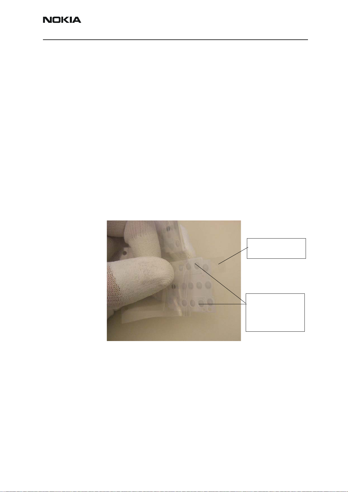
The dome sheet is delivered on transparency foil. First step is to remove the dome sheet
from the foil, where you need to ensure that the complete dome sheet is lifted and the
protecting foil on the other side of the dome sheet still sticks on the dome sheet. Please
see picture below:
Protecting foil will
stick on dome sheet
All dome sheet parts
are lifted.
(Nothing sticks on
the bottom foil.)
Issue 1 07/04 Nokia Corporation Page 11
Page 12

RH-37
5 - Disassembly Instructions Nokia Customer Care
Place the dome sheet onto the cleaned light guide and press them firmly together.
Take care, that the holes of the domesheet align exactly with the holes on the lightguide.
Page 12 Nokia Corporation Issue 1 07/04
Page 13

RH-37
Nokia Customer Care 5 - Disassembly Instructions
Placing the light guide assembly onto the PWB
In some regions there is the possibility to order the light guide assembly including the
dome sheet. In any case the protecting foil needs to be carefully removed from the dome
sheet.
Then place the assembly to the PWB and press it firmly together.
Note: It is very important to press the light guide assembly and the PWB properly together at any
point. If some points are not pressed properly together dust and humidity will sneak between PWB
and dome sheet and will cause corrosion, which lead usability problems and to a defect which might
lead to a total loss of the phone.
Now you can be continue with the assembly procedure.
Issue 1 07/04 Nokia Corporation Page 13
Page 14

RH-37
5 - Disassembly Instructions Nokia Customer Care
[This page left intentionally blank]
Page 14 Nokia Corporation Issue 1 07/04
 Loading...