

Page 1

Programmes After Market Services
NHE–8/9
Carkit Installation Guides
Page 2

Car kit Installation Guide PAMS
Technical DocumentationNHE–8/9
NHE–8 INSTALLATION INSTRUCTIONS
Contents
Introduction 3. . . . . . . . . . . . . . . . . . . . . . . . . . . . . . . . . . . . . . . . . . . . . . . . . . . . . .
General 3. . . . . . . . . . . . . . . . . . . . . . . . . . . . . . . . . . . . . . . . . . . . . . . . . . . . . .
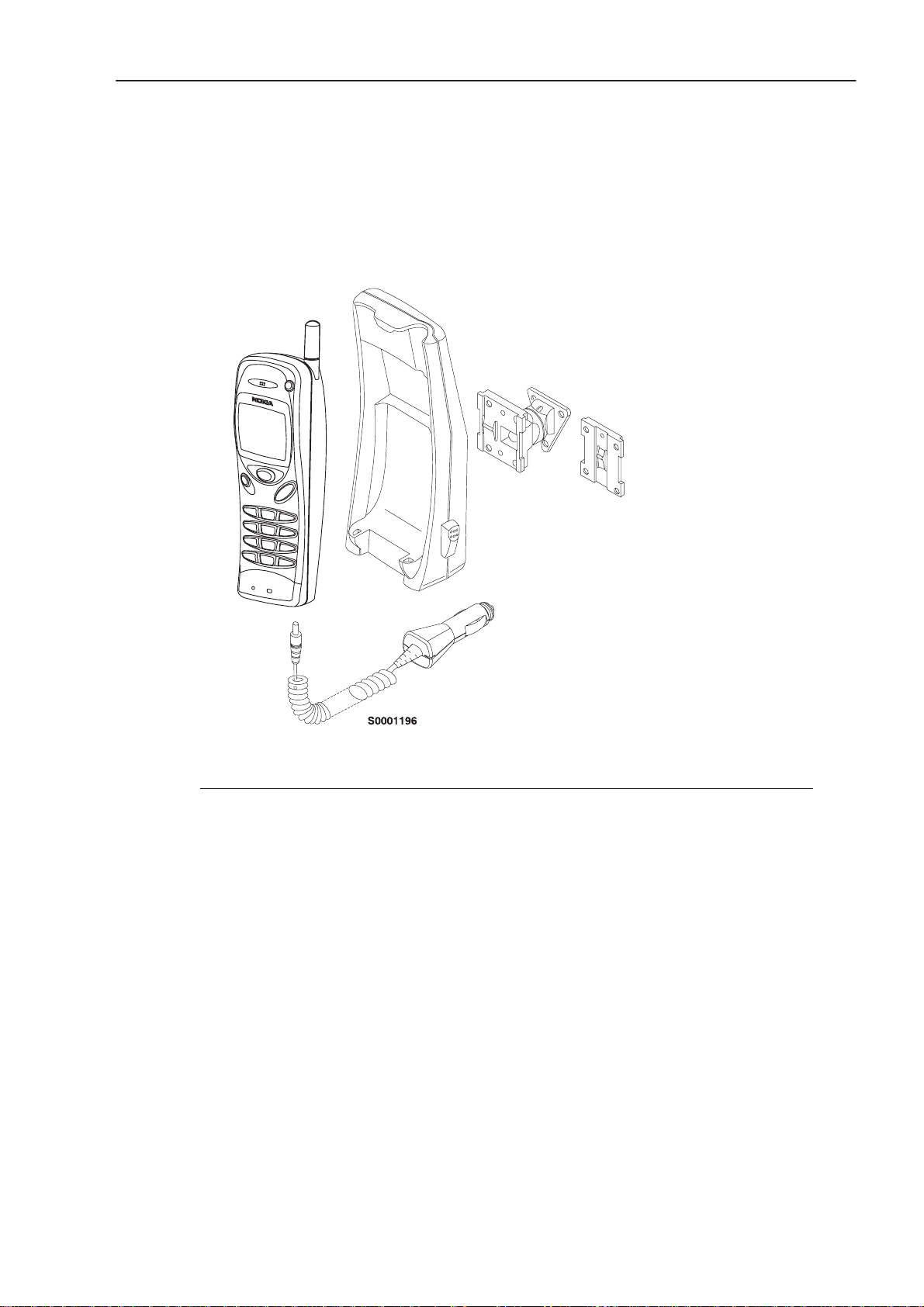
Basic Car Kit (CARK–48) 4. . . . . . . . . . . . . . . . . . . . . . . . . . . . . . . . . . . . . . . . . .
Professional Car Kit (CARK–74) 5. . . . . . . . . . . . . . . . . . . . . . . . . . . . . . . . . . . .
Component Parts 6. . . . . . . . . . . . . . . . . . . . . . . . . . . . . . . . . . . . . . . . . . . . .
Installation 9. . . . . . . . . . . . . . . . . . . . . . . . . . . . . . . . . . . . . . . . . . . . . . . . . . .
T esting 12. . . . . . . . . . . . . . . . . . . . . . . . . . . . . . . . . . . . . . . . . . . . . . . . . . . . . . . . . .
Page
2 issue 2 11/97
Page 3

PAMS
Car kit Installation Guide
Technical Documentation
Introduction
General
This installation guide has been prepared to provide the basic information
necessary to install car kits. This guide is not intended to be definitive,
because different types and models of vehicle will require different
installation work. The information given is for general guidance only.
The terms of warranty demand that this car kit be installed by an experienced
installation facility. An end user should never attempt to install this car kit
without professional assistance as the installation requires special tools and
knowledge.
Please refer to the telephone’s user guide for instructions on the telephone’s
operation, care and maintenance, including important safety information.
Note: Read the warnings below before beginning the installation procedure.
NHE–8/9
WARNINGS
4 ENSURE THAT THE VEHICLE BATTERY IS DISCONNECTED BEFORE YOU
START THE INSTALLATION PROCEDURE, AND THAT IT REMAINS DISCONNECTED DURING THE PROCEDURE.
5 DO NOT SMOKE OR USE OPEN FLAMES WHEN WORKING NEAR THE VE-
HICLE’S FUEL SYSTEM.
6 ENSURE THAT ELECTRICAL CABLES, HYDRAULIC LINES AND FUEL
LINES ARE NOT DAMAGED DURING INST ALLATION.
7 ENSURE THAT NORMAL CONTROL AND OPERATION OF THE VEHICLE IS
NOT IMP AIRED BY THE INSTALLATION, PARTICULARLY THE BRAKES
AND STEERING.
8 AL THOUGH ELECTRONIC SPEED CONTROL, ABS ANTI–LOCK BRAKE
AND FUEL INJECTION SYSTEMS ARE RELA TIVELY IMMUNE TO MALFUNCTION CAUSED BY NEARBY RADIO TRANSMISSIONS, SHOULD YOU
EXPERIENCE FALSE OPERATION OF THESE SYSTEMS OR ARE IN ANY
DOUBT WHA TSOEVER AS TO THEIR FUNCTIONALITY, PLEASE CONSUL T
THE VEHICLE DEALER.
9 THE CAR KIT IS SUITABLE FOR USE ONLY IN VEHICLES WITH A 11..32 V
NEGATIVE GROUNDING. USE ON OTHER SUPPL Y VOLTAGES OR ALTERNATIVE POLARITY WILL DAMAGE THE EQUIPMENT.
10 THE PHONE SHOULD NOT BE LEFT SWITCHED ON FOR EXTENDED PE-
RIODS WITHOUT RUNNING THE VEHICLE’S ENGINE. FAILURE T O COMPLY COULD DRAIN THE VEHICLE’S BA TTERY.
issue 2 11/97
Page
3
3
Page 4
Car kit Installation Guide PAMS
Technical DocumentationNHE–8/9
Basic Car Kit (CARK–48)
MBT–5
HHS–7
MKE–7
LCH–6
Product Name: Type: Code:
Phone Holder MBT–5 0620030
Mounting Plate MKE–7 065002
Swivel Mounting Plate HHS–7 0650020
Universal Mobile Charger LCH–6 0675076
Page
4 issue 2 11/97
Page 5

PAMS
Car kit Installation Guide
Technical Documentation
Professional Car Kit (CARK–74)
MBT–5
XHC–1
NHE–8/9
PHF–3
HHS–7
MKE–7
AAH–1D
For External Antenna
(not supplied)
Product Name: Type: Code:
Phone Holder MBT–5 0620030
Standard Handsfree Unit PHF–3 0694030
Mounting Plate MKE–7 0650021
Swivel Mounting Plate HHS–7 0650020
Power Cable PCH–4J 0730055
External Antenna Unit AAH–1D 0750077
Handsfree Microphone HFM–7 0690002
Handsfree Speaker HFS–9 0690012
Extension Cable XHC–1 0730060
For Power
Cable PCH–4J
HFM–7
HFS–9
issue 2 11/97
Page
5
5
Page 6

Car kit Installation Guide PAMS
Technical DocumentationNHE–8/9
Component Parts
Mounting Plate MKE–7 and Swivel Mounting Plate HHS–7
MKE–7 is a fixed position mounting plate; HHS–7 is a swivel mounting plate
which allows for adjustable fixing. Both two mounting plates are
interchangeable.
Phone Holder MBT–5
The phone holder allows the phone to be firmly located in a convenient
position. The phone holder is attached to the vehicle’s interior using mounting
plate MKE–7 or alternatively swivel mounting plate HHS–7. The mounting
must be secured with a screw (delivered with MKE–7/HHS–7).
Universal Mobile Charger LCH–6
The universal mobile charger enables the phone to be charged via the
vehicle’s cigarette lighter socket. The charger connects to the phone via a
d.c. jack socket located on the base of phone. The supply voltage may vary
between 11 and 32 V.
External Antenna Unit AAH–1D
The external antenna unit allows an external antenna to be connected to the
phone’s antenna when the phone is located in the mobile holder. The
external antenna unit is fastened to the bottom of the phone holder as shown
below.
Page
Power is supplied either from the vehicle’s battery via the fixed mobile
charger, LCM–1 or from the cigarette lighter socket via the universal mobile
charger, LCH–6 (not supplied).
6 issue 2 11/97
Page 7

PAMS
Car kit Installation Guide
Technical Documentation
Fixed Mobile Charger LCM–1
The fixed mobile charger provides a power supply for the external antenna
unit and the mobile phone.
Output Power Cable PCC–2
The output power cable connects the fixed mobile charger to the external
antenna unit.
Power Cable PCM–5
The power cable connects the fixed mobile charger, LCM–1, to the vehicle’ s
power supply. The red wire must be connected to the + voltage supply
controlled by the vehicle’s ignition key via the supplied fused connector . The
black wire must be attached to a good negative GND connection.
Standard Handsfree Unit PHF–3
NHE–8/9
The standard handsfree unit enables the phone to operate in handsfree
mode. The unit is attached to the vehicle interior using mounting plate
MKE–7, or swivel mounting plate HHS–7. The mounting must be secured
with a screw (delivered with MKE–7/HHS–7). A temporary installation can
be achieved using installation belts (not supplied).
Power is supplied from the vehicle’s battery via the power cable PCH–4J. The
standard handsfree unit provides the power supply to the phone via the
system connector.
The HF microphone, HFM–7, connects to the
MIC socket. The phone holder
can be attached to the standard handsfree unit as shown.
issue 2 11/97
Page
7
7
Page 8

Car kit Installation Guide PAMS
Technical DocumentationNHE–8/9
Power Cable PCH–4J
The power cable connects the standard handsfree unit, PHF–3, to the
vehicle’s power supply. The red wire must be connected to the + voltage on
the vehicle’s battery via the supplied fused connector. The black wire must
be attached to a good negative GND connection.
The blue ignition sense (IGNS) wire is connected to +12 V voltage controlled
by the vehicle’s ignition key via the supplied fused connector. See section
”Ignition Sense”.
The yellow wire is used for car radio muting (XCRM). The line goes down to
0 volts during a call. See section ”Car Radio Muting”.
The green wire is used for motor antenna (AMC). The voltage in this output
is +12 V whenever the phone is on. See section ”Antenna Motor Control”.
Handsfree Microphone HFM–7
The HF microphone connects directly to the standard handsfree unit (to
socket).
Extension Cable XHC–1 (optional for PHF–3)
The extension cable allows a phone holder and an external antenna unit
together to be connected to the standard handsfree unit when the unit is
located on the place apart from the others. Ensure PHF–3 is located so that
the incoming voice from the internal speaker is loud enough.
External Mobile Antenna (not supplied)
The external antenna unit is designed to operate with a high quality external
antenna. However, due to many dif ferent types of antennas being available,
an antenna is NOT included as part of this kit. Please, consult the dealer to
find out which is the most suitable antena type for your installation.
MIC
Page
8 issue 2 11/97
Page 9

PAMS
Car kit Installation Guide
Technical Documentation
Installation
There are some important aspects that require special attention in
positioning car kit accessories.
The positioning of the phone holder is the most important factor when trying
to achieve the most comfortable position for the user. The location of the
holder should be selected so that the visibility of the phone’s display is good
under all lighting conditions, but not so that the driver’s attention is easily
distracted. The holder should be located so that the driver can easily reach
the keypad. Under no circumstances should the holder prevent the driver
from controlling or operating the vehicle in any way or observing traffic.
The fixed mobile charger can be installed in a hidden location, since there is
no need to disconnect cables during normal operation. Ensure the location
does not subject the unit and cables to moisture or mechanical pressure. Also
remember clean the mounting tape location properly before installing.
The handsfree microphone can be installed on the driver ’s sunvisor or the
A–pillar. Ensure the microphone is as close to the driver’s mouth as possible,
and attached to a surface that is mechanically quiet. The microphone should
be mounted at least 3 ft/1 m away from the handsfree unit speaker to avoid
acoustic feedback. See separate microphone installation guide.
NHE–8/9
Ensure cables are routed as far away as possible from the vehicle’s
electronic systems (refer to WARNINGS). Also ensure cables are not
subjected to undue mechanical stress e.g. under seats or against sharp
edges. The external antenna adapter should always be connected to the
antenna via a non–radiating cable (e.g. coax).
The most important component of the installation is the antenna. The location
of the antenna as well the quality of the antenna and its installation have a
considerable influence to the overall performance of the whole system.
Therefore it is necessary to emphasize some aspects, which too often have
caused unnecessary service work.
The best place for the antenna is the rooftop. The overall performance of a
rooftop antenna is clearly superior to any other antenna type or location. The
Antenna shall be mounted in a position such that no part of human body will
normally rest too close to any part of the antenna unless there is a an
interventing metallic screen, for example, the metallic roof.
• highest place in the car
• proper ground place
• omnidirectional radiation pattern
• minimum risk for disturbances
• user safety
issue 2 11/97
Page
9
9
Page 10

Car kit Installation Guide PAMS
Technical DocumentationNHE–8/9
After drilling the hole for the antenna remember to clean the hole from the
drilling swarf, so that surface is even. This is needed in order to ensure proper
and reliable connection between the ground plane and the antenna. After
cleaning it is advised to apply some rust–proofing compound to the hole.
Mount the base of the antenna tightly to its place. Consult the antennas
manuals for determing the maximum bending angle before attempting any
bending operation.
To avoid drilling a hole in the vehicle’s bodywork, a glass–mounted antenna
can be chosen and located on the rear window of the vehicle.
Try to route the antenna cable so that possible sources of disturbances are
avoided, as well anti–skid brake systems. The shorter the antenna cable, the
smaller the attenuation, and the better the performance of the antenna. The
antenna coupler should always be connected to the antenna via a
non–radiating cable (e.g. coax).
Most of the antennas today have adapted the minigrimp connector system
which eliminates the need for special grimping tools and connectors. If
however the purchased antenna has traditional connectors, use only proper
connectors and tools. The antenna coupler uses TNC–female type antenna
connector for reasons of reliability and attennuation.
Ignition Sense IGNS
The ignition sense feature prevents your car kit from draining the car battery
by executing an auto power off in 20 seconds after the ignition key has been
turned off. The blue wire of the power cable is used for the ignition sense
feature. The use of ignition sense is recommended to prevent accidental
draining of the car’s battery. The wire is connected via a 1 A fuse to a 12/24
volt potential that is controlled by the ignition key. Do not connect it directly
to the high voltage sections of the ignition circuit.
Car Radio Muting CRM
The car kit offers a feature that can mute the car radio automatically during
a conversation. This feature is convenient and provides for safer handsfree
operation. The car radio muting feature is based on a grounded line, so it
means that in standby , the yellow wire (XCRM) is not grounded and car radio
works normally, but during a call, line is grounded and car radio is muted.
Note that an auxiliary relay or muting unit must be used when the car radio
doesn’t have a mute feature available.
Page
When a relay is used, connect in series with the car radio main supply. A
200 mA fuse should be used to protect the XCRM output in event of a short
circuit. Some radios have separate supplies for amplifiers and motors, and
another for memory backup purposes.
10 issue 2 11/97
Page 11

PAMS
Car kit Installation Guide
Technical Documentation
V ery often these radios also have a secret code system, which activates itself
if a break in the memory supply is detected. Be careful when installing the
relay not to break the memory supply (usually marked ACC or +MEM), but
to install the relay in the main supply feed.
GND
T o XCRM line
(yellow wire)
CAR
RADIO
Another possibility is to use a special muting unit, which mutes the radio by
connecting load resistors to the speaker lines of the car radio.
87A
NHE–8/9
Bosch P/N 0–332–204–150
12 V, 30 A. SPDT
30
87
85
86
Fuse 200 mA
(not supplied)
12 V d.c.
Supply for
car radio
12 V d.c.
Antenna Motor Control AMC
The antenna motor control offers a feature, green wire of the system cable
(AMC), that may be used to control different devices on and off. The voltage
in this output is +12 V whenever the phone is on. If the phone is turned off,
the voltage disappears. The maximum output current is 200 mA, therefore
for example motorized antenna must be controlled via a relay, see picture
below.
Bosch P/N 0–332–204–150 12 V,
30 A. SPDT
12 V d.c.
Supply for device
From AMC line (green
wire)
Fuse 1 A
All installations should take into account any special requirements of the
customer. However , should the customer require an installation that is illegal
or unsafe these facts must be pointed out to the customer and a policy of
non–compliance adopted.
87A
30
CONTROLLED
DEVICE e.g.
87
MOTOR ANTENNA
86
85
GND
GND
issue 2 11/97
Page
11
11
Page 12

Car kit Installation Guide PAMS
Technical DocumentationNHE–8/9
Testing
Once installed, the equipment should be tested to ensure that it is operating
satisfactorily and that the position of the units does not impair on the driver’s
ability to control and operate the vehicle in any way.
Use the phone to make a call when the vehicle is parked with the engine
running. During the call, switch off the engine. Ensure that the phone is
operational with the engine running and with the engine switched off. For
operating information refer to the ’Owner’s Manual’ supplied with the phone.
Page
12 issue 2 11/97
 Loading...