

Page 1

Programmes After Market Services
NHA–9 Series Transceivers
Disassembly
Issue 2 03/00
Page 2

NHA–9
PAMS
Disassembly
Technical Documentation
Contents
Disassembly Instructions (version1) 3. . . . . . . . . . . . . . . . . . . . . . . . . . . . . . . .
Antenna Removal 3. . . . . . . . . . . . . . . . . . . . . . . . . . . . . . . . . . . . . . . . . . . . .
Battery Pack / Battery Cover 4. . . . . . . . . . . . . . . . . . . . . . . . . . . . . . . . . . . .
B Cover Removal 5. . . . . . . . . . . . . . . . . . . . . . . . . . . . . . . . . . . . . . . . . . . . .
Headset Connector, Headset Cover, Vibra Motor and Antenna Tube 6.
Engine PCB 6. . . . . . . . . . . . . . . . . . . . . . . . . . . . . . . . . . . . . . . . . . . . . . . . . .
Mic + Boot 6. . . . . . . . . . . . . . . . . . . . . . . . . . . . . . . . . . . . . . . . . . . . . . . . . . .
Cinch Connector 7. . . . . . . . . . . . . . . . . . . . . . . . . . . . . . . . . . . . . . . . . . . . . .
Lid module 8. . . . . . . . . . . . . . . . . . . . . . . . . . . . . . . . . . . . . . . . . . . . . . . . . . .
Keymat Module 9. . . . . . . . . . . . . . . . . . . . . . . . . . . . . . . . . . . . . . . . . . . . . . .
Power Button & Call indicator lens 9. . . . . . . . . . . . . . . . . . . . . . . . . . . . . . .
NHA–9 (version 1) Disassembled 10. . . . . . . . . . . . . . . . . . . . . . . . . . . . . . .
Re–Assembly 11. . . . . . . . . . . . . . . . . . . . . . . . . . . . . . . . . . . . . . . . . . . . . . . . .
Lid Module 11. . . . . . . . . . . . . . . . . . . . . . . . . . . . . . . . . . . . . . . . . . . . . . . .
Cinch Connector 12. . . . . . . . . . . . . . . . . . . . . . . . . . . . . . . . . . . . . . . . . . .
Engine PCB 13. . . . . . . . . . . . . . . . . . . . . . . . . . . . . . . . . . . . . . . . . . . . . . .
Antenna 14. . . . . . . . . . . . . . . . . . . . . . . . . . . . . . . . . . . . . . . . . . . . . . . . . . .
Disassembly Instructions (version2) 15. . . . . . . . . . . . . . . . . . . . . . . . . . . . . . . .
Antenna Removal 15. . . . . . . . . . . . . . . . . . . . . . . . . . . . . . . . . . . . . . . . . . . . .
Battery Pack / Battery Cover 16. . . . . . . . . . . . . . . . . . . . . . . . . . . . . . . . . . . .
B Cover Removal 17. . . . . . . . . . . . . . . . . . . . . . . . . . . . . . . . . . . . . . . . . . . . .
Headset Connector, Headset Cover, Vibra Motor and Antenna Tube 18.
Engine PCB 18. . . . . . . . . . . . . . . . . . . . . . . . . . . . . . . . . . . . . . . . . . . . . . . . . .
Mic + Boot 19. . . . . . . . . . . . . . . . . . . . . . . . . . . . . . . . . . . . . . . . . . . . . . . . . . .
Keymat Module 19. . . . . . . . . . . . . . . . . . . . . . . . . . . . . . . . . . . . . . . . . . . . . . .
Lid Module 19. . . . . . . . . . . . . . . . . . . . . . . . . . . . . . . . . . . . . . . . . . . . . . . . . . .
NHA–9 (version 2) Disassembled 20. . . . . . . . . . . . . . . . . . . . . . . . . . . . . . .
Re–Assembly 21. . . . . . . . . . . . . . . . . . . . . . . . . . . . . . . . . . . . . . . . . . . . . . . . .
Lid Module 21. . . . . . . . . . . . . . . . . . . . . . . . . . . . . . . . . . . . . . . . . . . . . . . .
Engine PCB 22. . . . . . . . . . . . . . . . . . . . . . . . . . . . . . . . . . . . . . . . . . . . . . .
Page 2
Antenna 23. . . . . . . . . . . . . . . . . . . . . . . . . . . . . . . . . . . . . . . . . . . . . . . . . . .
Issue 2 03/00
Page 3
PAMS
NHA–9
Technical Documentation
Disassembly Instructions (version1)
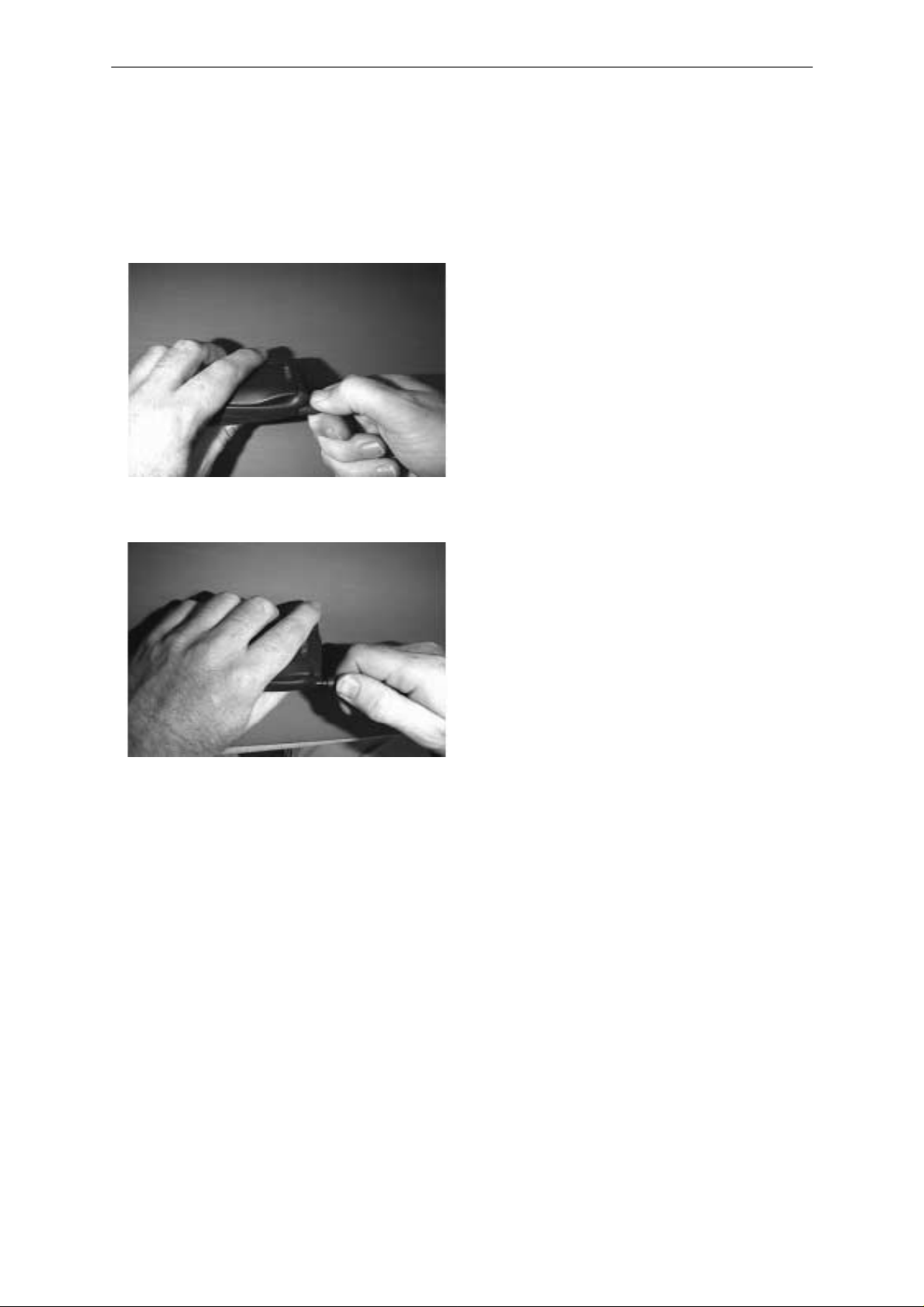
Antenna Removal
Apply a two step movement
Rotate clockwise approx 90 degrees
whilst pulling slightly.
Disassembly
The antenna will stop 1–2 mmm out of
the B cover
Rotate clockwise approx 90 degrees
whilst pulling the antenna completely
out
Issue 2 03/00
Page 3
Page 4
NHA–9
PAMS
Disassembly
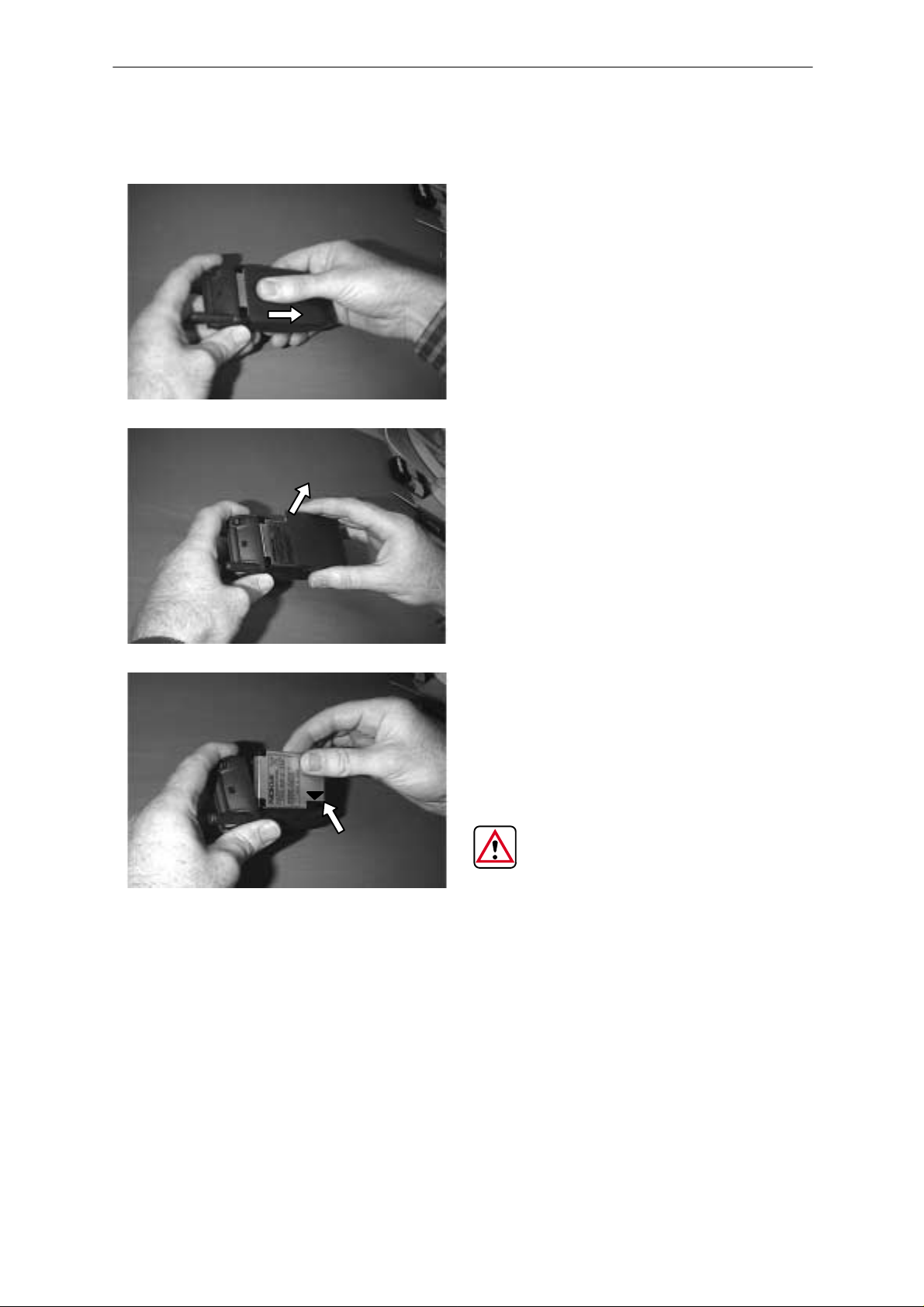
Battery Pack / Battery Cover
Technical Documentation
Pull the battery cover until it stops
Lift up the battery cover
Remove the battery pack
DURING RE–ASSEMBLY, ENSURE THA T THE CONTACTS ARE
ALIGNED (SEE ARROW)
Page 4
Issue 2 03/00
Page 5
PAMS
NHA–9
Technical Documentation
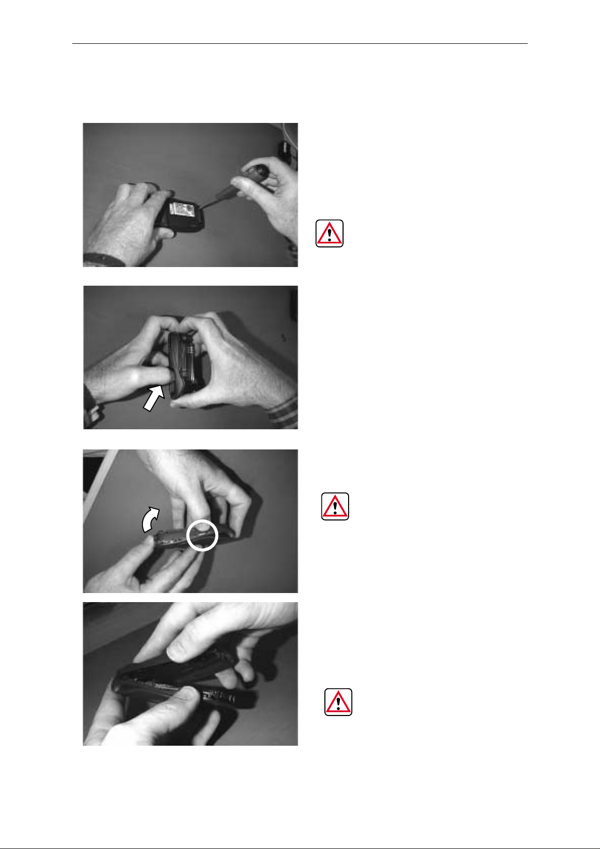
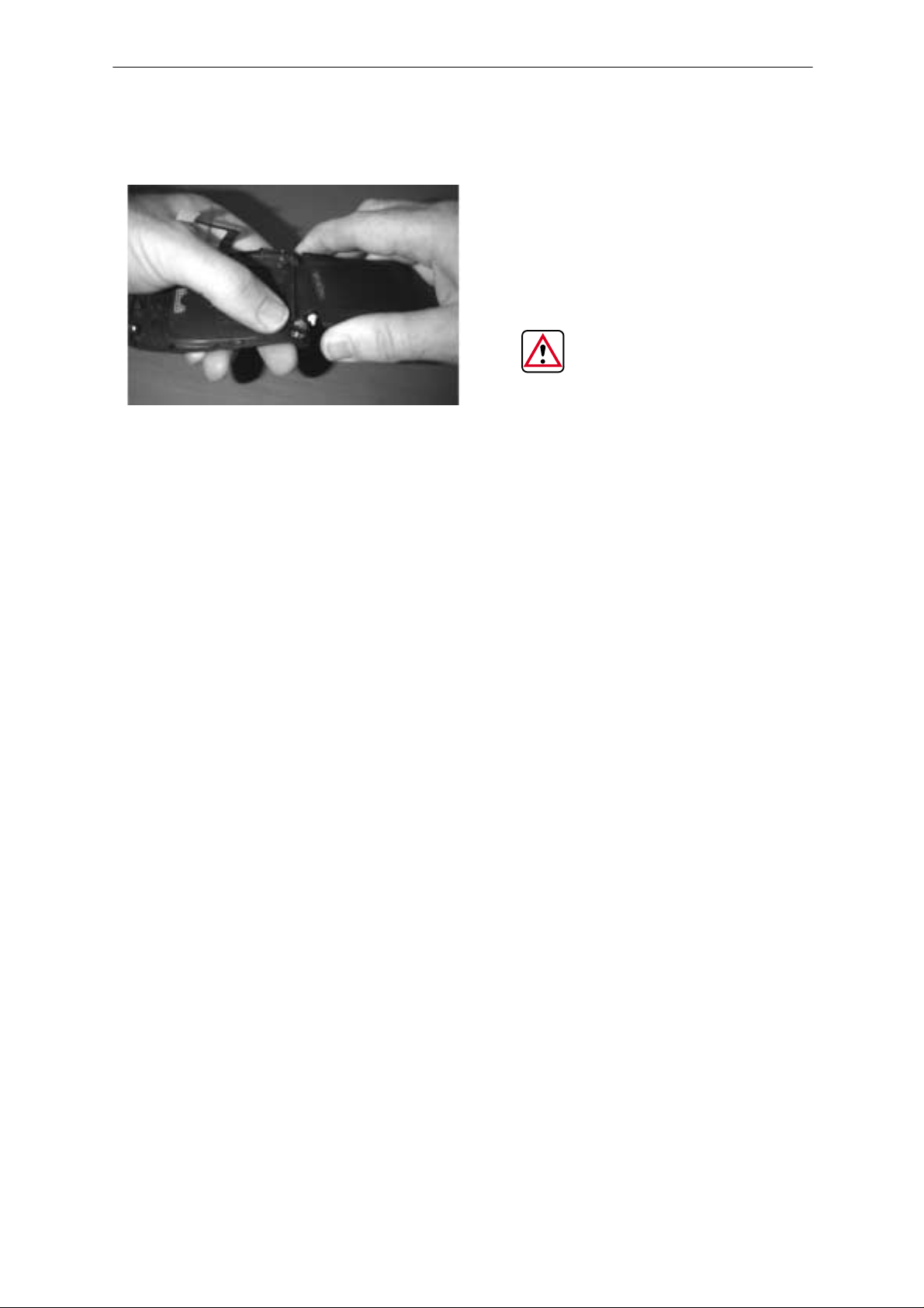
B Cover Removal
Disassembly
Remove 2 TORX screws,
turn anti–clockwise
THE NOMINAL TORQUE
TO APPLY DURING THE
RE–ASSEMBLY IS 12 N/cm
+/– 0.5 N/cm
Whilst holding the phone as
shown, disengage the clips
on both sides of the phone
with your thumbnail
THE CLIPS ON BOTH
SIDES OF THE PHONE ARE
FRAGILE. DO NOT PULL
THE B COVER WITHOUT
DISENGAGING THE SIDE
CLIPS FIRST
Once the clips are disengaged, lift up the bottom of
the B cover gently
DURING RE–ASSEMBLY
MAKE SURE THAT ALL
CLIPS ARE ENGAGED
(THE 2 SIDE CLIPS AND
THE TOP CLIP)
Issue 2 03/00
Page 5
Page 6
NHA–9
PAMS
Disassembly
Technical Documentation
Headset Connector, Headset Cover, Vibra Motor and Antenna Tube
If required, remove the headset connector, headset cover, vibra motor and
antenna tube (not shown)
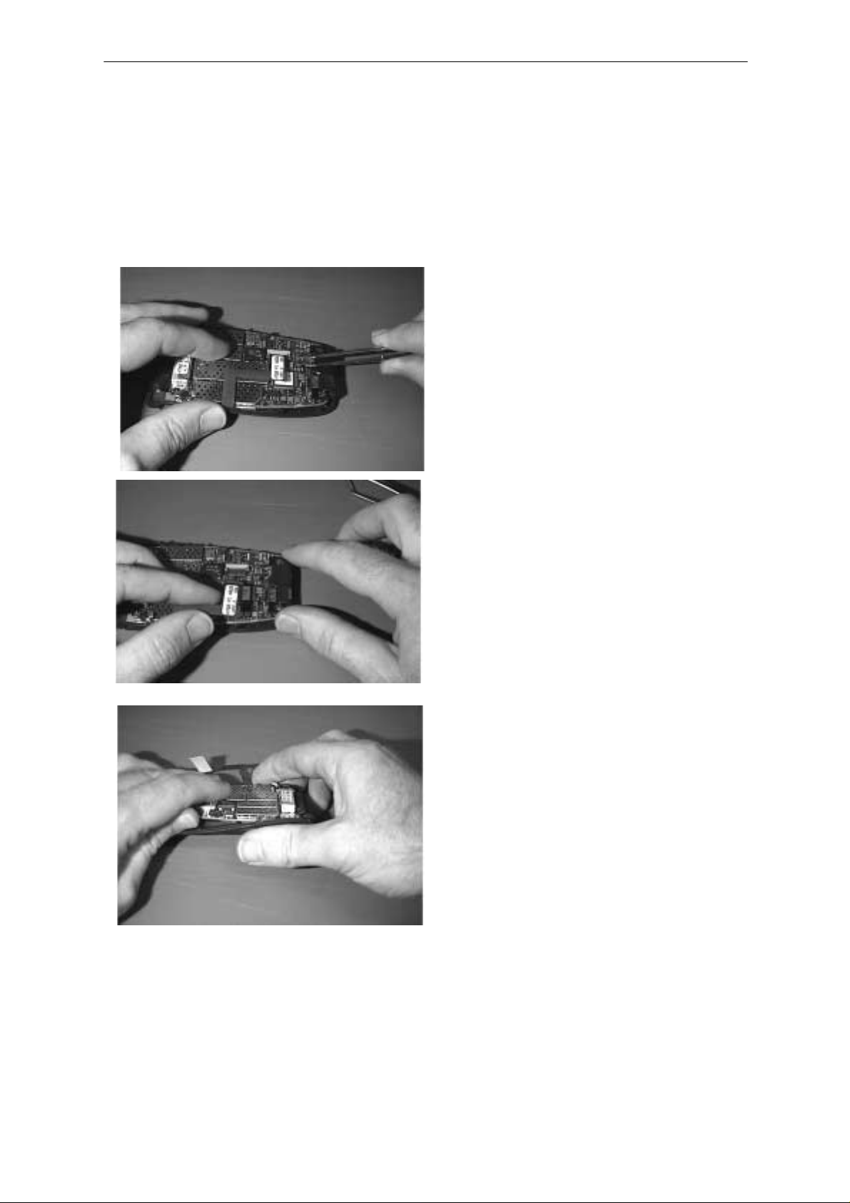
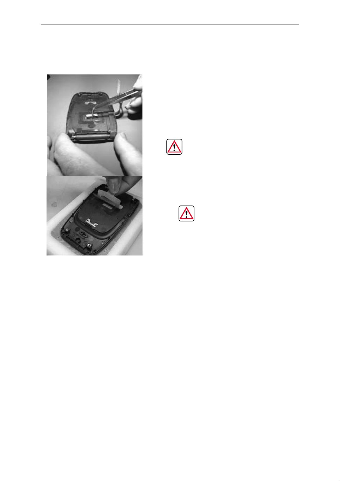
Engine PCB
Disconnect the flexi from the
engine PCB using
tweezers
Mic + Boot
Remove the Mic + Boot from the engine PCB if required ( not shown)
Page 6
Lift up , gently slide the side of
the engine PCB, opposite to
the flexi, whilst holding the A
cover
Issue 2 03/00
Page 7
PAMS
NHA–9
Technical Documentation
Cinch Connector
Disassembly
Remove the cinch connector
using tweezers.It may only
be re–used in repair module
jig (MJS–7).
EACH TIME THE ENGINE
BOARD IS REMOVED, THE
CINCH MUST BE REPLACED BY
A NEW ONE
EACH TIME THE PHONE IS
OPENED THE PCB ADHESIVE
WINDOW MUST BE REPLACED
Issue 2 03/00
Page 7
Page 8
NHA–9
PAMS
Disassembly
Lid module
Technical Documentation
Open the lid and disengage the
hinge opposite to the flexi
BE CAREFUL NOT TO
DAMAGE THE FLEXI
Page 8
Issue 2 03/00
Page 9

PAMS
NHA–9
Technical Documentation
Keymat Module
To be removed only when necessary
Disassembly
Bend the top of the A cover
and remove the top layers of the
keymat module
Power Button & Call indicator lens
If required, remove the power button and indicator lens from the A cover
(not shown)
Using a scalpel and some tweezers, remove the bottom layer of
the keymat module
WHENEVER A KEYMAT
MODULE IS REMOVED, IT
MUST BE REPLACED BY A
NEW ONE
Issue 2 03/00
Page 9
Page 10

NHA–9
PAMS
Disassembly
NHA–9 (version 1) Disassembled
Technical Documentation
Page 10
Issue 2 03/00
Page 11

PAMS
NHA–9
Technical Documentation
Re–Assembly
To re–assemble, refer to the disassembly instructions in reverse order,
paying attention to the following re–asemblies
S Lid Module
S Cinch Connector
S Engine PCB
S Antenna
Lid Module
BE CAREFUL NOT TO DAMAGE THE
FLEXI DURING THIS RE–ASSEMBLY
Disassembly
Place the flexi side of the
module in the A cover being careful not to damage
the flexi
Push the hinge in its location
Issue 2 03/00
Place the other side of the
hinge in its location
Page 11
Page 12

NHA–9
PAMS
Disassembly
Cinch Connector
THE CINCH CONNECTOR IS FRAGILE, IT MUST BE HANDLED WITH
TWEEZERS. THE PACKAGING SHOULD BE CLOSED AFTER USAGE
TO ENSURE THE CONNECTOR IS RETAINED UNDER COMPRESSION
Technical Documentation
Close the lid being careful
not to damage the flexi.
Put the phone on the
bench
Take a cinch connector
from its tray using tweezers
Place the cinch in its position
Page 12
Issue 2 03/00
Page 13

PAMS
NHA–9
Technical Documentation
Engine PCB
Disassembly
Align the engine PCB with the
locating clips either side of the
A cover
Ensure that the flexi:
– is in the cutout in the A cover.
– is under the PCB
– runs along the groove provided
Then, press the PCB firmly into place
Make sure the flexi is positioned
in the PCB cut out.
Connect the flexi to the engine PCB
Issue 2 03/00
Page 13
Page 14

NHA–9
PAMS
Disassembly
Antenna
Technical Documentation
Locate the antenna position and
push the antenna home
Page 14
Issue 2 03/00
Page 15

PAMS
NHA–9
Technical Documentation
Disassembly Instructions (version2)
Antenna Removal
Apply a two step movement
Rotate clockwise approx 90 degrees
whilst pulling slightly.
Disassembly
The antenna will stop 1–2 mmm out of
the B cover
Rotate clockwise approx 90 degrees
whilst pulling the antenna completely
out
Issue 2 03/00
Page 15
Page 16

NHA–9
PAMS
Disassembly
Battery Pack / Battery Cover
Technical Documentation
Pull the battery cover until it stops
Lift up the battery cover
Remove the battery pack
DURING RE–ASSEMBLY, ENSURE
THAT THE CONTACTS ARE
ALIGNED (SEE ARROW)
Page 16
Issue 2 03/00
Page 17

PAMS
NHA–9
Technical Documentation
B Cover Removal
Disassembly
Remove 2 TORX screws,
turn anti–clockwise
THE NOMINAL TORQUE
TO APPLY DURING THE
RE–ASSEMBLY IS 16 N/cm
+/– 0.5 N/cm
Whilst holding the phone as
shown, disengage the clips
on both sides of the phone
with your thumbnail
THE CLIPS ON BOTH
SIDES OF THE PHONE ARE
FRAGILE. DO NOT PULL
THE B COVER WITHOUT
DISENGAGING THE SIDE
CLIPS FIRST
With a precision screw driver, or
some tweezers, disengage the
top center clips.
Once the clips are disengaged,
lift up the bottom of the B cover
gently and remove it completely
DURING RE–ASSEMBLY
MAKE SURE THAT ALL
CLIPS ARE ENGAGED
(THE 2 SIDE CLIPS AND
THE TOP CLIP)
Issue 2 03/00
Page 17
Page 18

NHA–9
PAMS
Disassembly
Technical Documentation
Headset Connector, Headset Cover, Vibra Motor and Antenna Tube
If required, remove the headset connector, headset cover, vibra motor and
antenna tube from the B cover.
Engine PCB
Disconnect the flexi from the
engine PCB using tweezers
Lift up , gently slide the side of
the engine PCB, opposite to
the flexi, whilst holding the A
cover
Page 18
Issue 2 03/00
Page 19

PAMS
NHA–9
Technical Documentation
Mic + Boot
Remove the Mic + Boot from the engine PCB if required ( not shown)
Keymat Module
Disassembly
Remove the keymat module
from the A cover
Lid Module
Open the lid and disengage
the hinge opposite to the flexi
Issue 2 03/00
Page 19
Page 20

NHA–9
PAMS
Disassembly
NHA–9 (version 2) Disassembled
Technical Documentation
Page 20
Issue 2 03/00
Page 21

PAMS
NHA–9
Technical Documentation
Re–Assembly
To re–assemble, refer to the disassembly instructions in reverse order,
paying attention to the following re–assemblies
S Lid Module
S Cinch Connector
S Engine PCB
S Antenna
Lid Module
BE CAREFUL NOT TO DAMAGE THE
FLEXI DURING THIS RE–ASSEMBLY
Disassembly
Place the flexi side of the
module in the A cover being careful not to damage
the flexi
Place the hinge in its location
and place the other side of the
hinge in the A cover
Issue 2 03/00
Page 21
Page 22

NHA–9
PAMS
Disassembly
Engine PCB
Technical Documentation
Ensure that the flexi is
properly positioned at the
hinge location
Place the keypad module
in the A cover (not shown)
Position the engine PCB in the A cover,
ensuring that the flexi:
– Runs along the groove provided
– Is under the PCB
– Is in the cut–out in the A cover
Make sure the flexi is positioned
in the PCB cut out.
Page 22
Connect the flexi to the engine PCB
Issue 2 03/00
Page 23

PAMS
NHA–9
Technical Documentation
Antenna
Disassembly
Locate the antenna position and
push the antenna home
Issue 2 03/00
Page 23
Page 24

[This page intentionally left blank]
 Loading...