

Page 1

Nokia Customer Care
RH-53/54
6-Disassembly and
Assembly Instructions
ISSUE 1 09/2004 Copyright © 2004 Nokia Corporation. All rights Reserved
Page 2

RH-53/54
Nokia Customer Care 6-Disassembly and Assembly Instructions
[This page left intentionally blank]
2 COMPANY CONFIDENTIAL ISSUE 1 09/2004
Copyright © 2004 Nokia. All Rights Reserved.
Page 3

RH-53/54
6-Disassembly and Assembly Instructions Nokia Customer Care
Table of Contents
Page No
RH-53/54 Disassembly........................................................................................ 5
Domesheet Exchange instructions .................................................................12
RH-53/54 Reassembly....................................................................................... 14
ISSUE 1 09/2004 COMPANY CONFIDENTIAL 3
Copyright © 2004 Nokia. All Rights Reserved.
Page 4

RH-53/54
Nokia Customer Care 6-Disassembly and Assembly Instructions
[This page left intentionally blank]
4 COMPANY CONFIDENTIAL ISSUE 1 09/2004
Copyright © 2004 Nokia. All Rights Reserved.
Page 5
RH-53/54
6-Disassembly and Assembly Instructions Nokia Customer Care
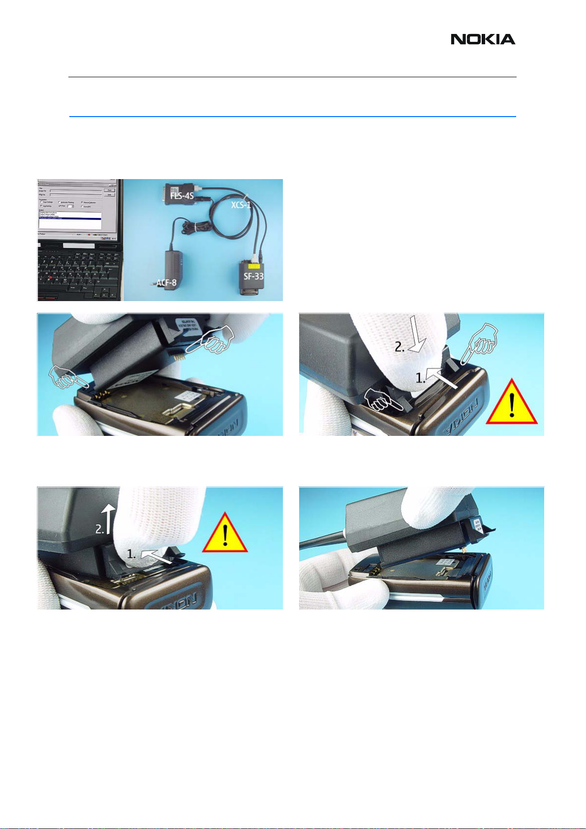
RH-53/54 Disassembly
Disassembly instructions
It is very important to follow this insertion and
removal procedure, otherwise the contact pins of
Flash Adapter will be damaged.
1.) Insert the Flash Adapter SF-33 by starting at the
Battery Connector side.
3.) When removing the Flash Adapter, press the locking
as shown in the picture.
2.) First, press the locking of the Flash Adapter and then
push it into the bottom side of the phone, do not use too
much force.
4.) Take away the unit now.
ISSUE 1 09/2004 COMPANY CONFIDENTIAL 5
Copyright © 2004 Nokia. All Rights Reserved.
Page 6

RH-53/54
Nokia Customer Care 6-Disassembly and Assembly Instructions
1.) Push down the Release Button before pulling the
Battery Cover.
3.) The Backplate is attached to the Hinge Spring with
two adhesive tapes. To avoid the snaps from breaking it
is important that the Backplate is at first lifted on the right
side referring to the "NOKIA" logo.
2.) Open the unit and protect the Window with a plastic
film.
4.) Now, remove the Backplate adhesive. If necessary
clean the Backplate and the Hinge Spring before
attaching using new Backplate Adhesives.
5.) A-Face Assy is attached with snaps to the B-Cover
Lower Block. Release the two snaps first.
6 COMPANY CONFIDENTIAL ISSUE 1 09/2004
Copyright © 2004 Nokia. All Rights Reserved.
6.) Shift the A-Face Assy from the B-Cover as shown in
the picture.
Page 7

RH-53/54
6-Disassembly and Assembly Instructions Nokia Customer Care
7.) Fold the A-Face Assy as shown in the picture.
9.) Protect the inner side of the Window with a plastic
film.
8.) Remove the A-Face Assy from the B-Cover Upper
Block carefully.
10.) Unscrew the four T orx Plus® size 6 screws of Upper
Block. For assembly, the reverse order and a Torx Plus
driver with a torque of 27Ncm has to be used.
®
1 1.) Unscrew the four Torx Plus® size 6 screws of Lower
Block. For assembly, the reverse order and a Torx Plus
driver with a torque of 27Ncm has to be used.
ISSUE 1 09/2004 COMPANY CONFIDENTIAL 7
Copyright © 2004 Nokia. All Rights Reserved.
12.) Now, the B-Cover Lower Block…
®
Page 8

RH-53/54
Nokia Customer Care 6-Disassembly and Assembly Instructions
Consider if the malfunction caused by Upper or
Lower Block. Only open the Coax Connector and
remove the Coax Cable on the defective Block of the
unit.
(For e.g. LCD / Vibra / IHF Speaker fault -> start disassemble upper part, Microphone / Key mat / Charger
fault -> start disassemble lower part)
13.) …and the B-Cover Upper Block can be removed.
14.) Placement of the Coax Cable in the Lower Block. 15.) Placement of the Coax Cable in the Hinge.
16.) Placement of the Coax Cable in the Upper Block.
17.) Placement of the Coax Cable in the IHF Antenna
Chamber.
18.) Open the Coax Connector of the Engine Module
carefully by using tweezers.
8 COMPANY CONFIDENTIAL ISSUE 1 09/2004
Copyright © 2004 Nokia. All Rights Reserved.
19.) Note the exactly position when laying the Coax
Cable during assembly.
Page 9

RH-53/54
6-Disassembly and Assembly Instructions Nokia Customer Care
20.) Remove the Cable carefully. When assembling
always starts with the Antenna Connector, "stretch" the
cable towards hinge area carefully, then the same procedure when assembling at Engine Module side.
22.) Put the Lower Block on the Upper Block as shown in
the Picture.
21.) Unscrew the two Torx Plus® size 5 screws from
®
Lower Block. For assembly, a Torx Plus
torque of 6Ncm has to be used.
23.) Lift the shown side of the Flex Connector carefully
by using the Flex Opening Tool as a lever.
driver with a
24.) Now, open the Connector carefully. 25.) Separate the Modules.
26.) Open the hooks before removing the Plastic Hinge. 27.) Take care not to damage the Flex Connector when
removing the Plastic Hinge.
ISSUE 1 09/2004 COMPANY CONFIDENTIAL 9
Copyright © 2004 Nokia. All Rights Reserved.
Page 10

RH-53/54
Nokia Customer Care 6-Disassembly and Assembly Instructions
28.) Unlock the snaps before removing the IHF Antenna
Chamber.
30.) Release the four hooks carefully by using the SRT-6.31.) Separate the C2-Cover from LCD CAN Assy.
29.) Remove the Antenna Chamber.
32.) Use tweezers when removing the Vibra Motor. 33.) Open the LCD Connector by using the SRT-6 carefully.
34.) Place the SRT -6 between LCD and the LCD Can as
shown in the picture and lever out the LCD caref ully.
10 COMPANY CONFIDENTIAL ISSUE 1 09/2004
Copyright © 2004 Nokia. All Rights Reserved.
35.) Release the four springs of Key Dome Shield.
Page 11

RH-53/54
6-Disassembly and Assembly Instructions Nokia Customer Care
36.) Now, the Key Dome Shield can be removed. 37.) The Engine Module can be removed easily.
38.) System Connector and Microphone drop out when
turning the Shielding Can.
ISSUE 1 09/2004 COMPANY CONFIDENTIAL 11
Copyright © 2004 Nokia. All Rights Reserved.
Page 12

RH-53/54
Nokia Customer Care 6-Disassembly and Assembly Instructions
Domesheet Exchange instructions
1.) Take care not to damage the LED’s when exchanging
the Domesheet. Start with SRT-6 as shown in the picture.
3.) Take the new Domesheet with tweezers. 4.) Place the Domesheet in the Key Dome Shield.
2.) Tweezers can be used to remove the defective
Domesheet.
5.) Place the Dome Sheet straps into the slot of the Key
Dome Shield.
12 COMPANY CONFIDENTIAL ISSUE 1 09/2004
Copyright © 2004 Nokia. All Rights Reserved.
6.) Same procedure on the opposite side.
Page 13

RH-53/54
6-Disassembly and Assembly Instructions Nokia Customer Care
7.) Make sure that the edges and the screw hole s of
Domesheet and the Key Dome Shield are congruent to
each other.
7.) Remove the Key Dome Shield again. 8.) Press on the Domesheet carefully. Ensure also, that
8.) Place the Key Dome Shield with the Domesheet on
the Engine Module exactly and press-on the Domesh eet
carefully. Check if the Domesheet is correctly stuck to
the Engine Module.
there are no open edges or air gap.
ISSUE 1 09/2004 COMPANY CONFIDENTIAL 13
Copyright © 2004 Nokia. All Rights Reserved.
Page 14

RH-53/54
Nokia Customer Care 6-Disassembly and Assembly Instructions
RH-53/54 Reassembly
The reassembly takes place in reversed order.
14 COMPANY CONFIDENTIAL ISSUE 1 09/2004
Copyright © 2004 Nokia. All Rights Reserved.
 Loading...