

Page 1

CONTENTS
INTRODUCTION
VEHICLE IDENTIFICATION AND
GENERAL SPECIFICATIONS
GENERAL INFORMATION
Tools and equipment ............................................. 8
Safety .................................................................... 10
General repair procedures..................................... 11
........................................
.................
......................
5
7
8
LUBRICATION AND MAINTENANCE... 14
Specifications......................................................... 14
How to grease and oil change .............................. 14
Service schedule ................................................... 17
WHEELS AND TYRES
Specifications......................................................... 21
How to change a road wheel ................................ 21
Tire wear trouble shooting..................................... 22
Care and maintenance ......................................... 23
ENGINE TUNE-UP
Tune-up specifications ........................................... 25
Tune-up operations ............................................... 25
ROADSIDE TROUBLE SHOOTING
Trouble shooting.................................................... 32
To check ignition and electrical system ................ 33
To check fuel system ............................................ 34
To check mechanical system................................ 35
ENGINE
Specifications ........................................................ 37
Engine mechanical trouble shooting...................... 39
Description ............................................................ 41
Engine and transaxle assembly ........................... 42
Manifolds............................................................... 44
Camshaft, rocker arms and tappets..................... 48
Cylinder head ........................................................ 50
Engine sump and oil pump pickup pipe................ 54
Oil pump ............................................................... 55
Pistons, connecting rods and cylinder bores ........ 57
Crankshaft and bearings...................................... 60
Flywheel /drive plate............................................... 63
Engine mountings.................................................. 64
Exhaust system.................................................... 66
.......................................................
.............................
....................................
.......
21
25
32
37
COOLING AND HEATING SYSTEMS.... 68
Specifications ........................................................ 68
Cooling system trouble shooting ........................... 68
Heater and air conditioner trouble shooting ......... 69
Description ............................................................ 70
Radiator ................................................................ 70
Cooling fan ............................................................ 73
Thermostat............................................................ 75
Thermostat housing .............................................. 76
Water pump .......................................................... 76
Welch plugs .......................................................... 76
Heater unit, water valve and controls................... 77
Blower fan ............................................................. 80
Air conditioning ..................................................... 80
FUEL AND ENGINE MANAGEMENT ... 82
Specifications ........................................................ 82
Fuel and engine management trouble shooting... 82
Description............................................................ 84
Service precautions and procedures ..................... 86
System diagnosis and adjustments...................... 89
Fuel supply components ....................................... 92
Air flow components.............................................. 98
Electronic components.......................................... 104
EMISSION CONTROL
Introduction ........................................................... 117
Crankcase ventilation system............................... 117
Evaporate control system ..................................... 117
Air preheat system — 1.6 liter engines ................ 119
Exhaust control system........................................ 120
CLUTCH
Specifications........................................................ 121
Clutch trouble shooting......................................... 121
Description............................................................ 122
Clutch unit and release mechanism..................... 123
Clutch pedal ......................................................... 124
Clutch cable.......................................................... 124
Clutch adjustments............................................... 125
MANUAL TRANSAXLE AND
DRIVE SHAFTS
Specifications........................................................ 126
Manual transaxle and drive shaft trouble shooting 126
Description............................................................ 128
Transaxle assembly.............................................. 129
Differential and final drive assembly ..................... 135
Gear lever assembly ............................................ 136
Drive shafts .......................................................... 137
......................................................
.........................................
AUTOMATIC TRANSAXLE
Specifications........................................................ 140
Automatic transaxle trouble shooting.................... 140
Description............................................................ 141
Transaxle fluid ...................................................... 141
Brake band........................................................... 142
Kickdown cable .................................................... 142
Transaxle selector linkage ................................... 142
Neutral safety switch............................................ 142
Transaxle assembly .............................................. 143
STEERING
PART 1. STEERING TROUBLE SHOOTING....145
Faults, causes and remedies................................ 145
PART 2. MANUAL STEERING......................... 147
Specifications........................................................ 147
Description............................................................ 147
Steering wheel ...................................................... 147
Steering column.................................................... 148
Steering gear assembly ....................................... 149
PART 3. POWER STEERING .......................... 152
Specifications........................................................ 152
Description............................................................ 152
In car adjustments, checks and minor repairs..... 152
Steering wheel ...................................................... 153
Steering column.................................................... 153
Power steering pump ........................................... 153
Power steering gear assembly............................. 154
.................................................
.............................
.......................
117
121
126
140
145
Page 2

FRONT SUSPENSION
Specifications......................................................... 156
Front suspension trouble shooting ........................ 156
Description ............................................................ 157
Steering knuckle.................................................... 157
Suspension unit..................................................... 159
Control arm ........................................................... 161
Stabiliser bar ........................................................ 162
Suspension and steering angles .......................... 163
REAR SUSPENSION
Specifications ........................................................ 164
Rear suspension trouble shooting ........................ 164
Description ............................................................ 165
Rear hub............................................................... 166
Suspension unit .................................................... 167
Control arm ........................................................... 169
Knuckle assembly.................................................. 170
Stabiliser bar ........................................................ 170
Rear wheel alignment ........................................... 171
BRAKES
Specifications......................................................... 172
Brakes trouble shooting ........................................ 172
Description ............................................................ 174
Master cylinder...................................................... 175
Brake servo unit .................................................... 177
Front brakes ......................................................... 178
Rear disc brakes................................................... 181
Rear drum brakes................................................. 184
Handbrake cable and lever assembly ................... 186
Brake adjustments ................................................ 187
Brake pedal........................................................... 187
Hydraulic system................................................... 188
......................................................
............................
................................
156
164
172
ELECTRICAL SYSTEM
Specifications......................................................... 190
Battery and charging system trouble shooting....... 190
Battery and starting system trouble shooting ........ 191
Lighting system trouble shooting ........................... 192
Turn signal lamp trouble shooting ........................ 192
Test equipment and some applications................. 193
Battery................................................................... 194
Alternator ............................................................... 196
Starter motor......................................................... 201
Ignition system ...................................................... 206
Steering wheel ....................................................... 206
Switches and controls........................................... 206
Instrument cluster.................................................. 209
Blower fan.............................................................. 209
Radio/cassette...................................................... 209
lamp units............................................................ 210
Windscreen wiper ................................................. 213
Fuses, fusible links and relays............................. 215
Trailer wiring......................................................... 216
Wiring diagrams ................................................... 218
BODY
Windscreen and rear glass .................................. 225
Front doors........................................................... 225
Rear doors............................................................ 228
Engine bonnet ...................................................... 231
Tailgate and lock — hatchback ............................ 231
Luggage compartment lid and lock — sedan ........ 233
Radiator grille.............................................................. 234
Centre console...................................................... 234
Dashboard............................................................ 235
Scat belts ............................................................. 236
Seats .................................................................... 236
Vehicle cleaning ........................................................... 237
...........................................................
CONVERSION TABLES
............................
..........................
190
225
238
Page 3

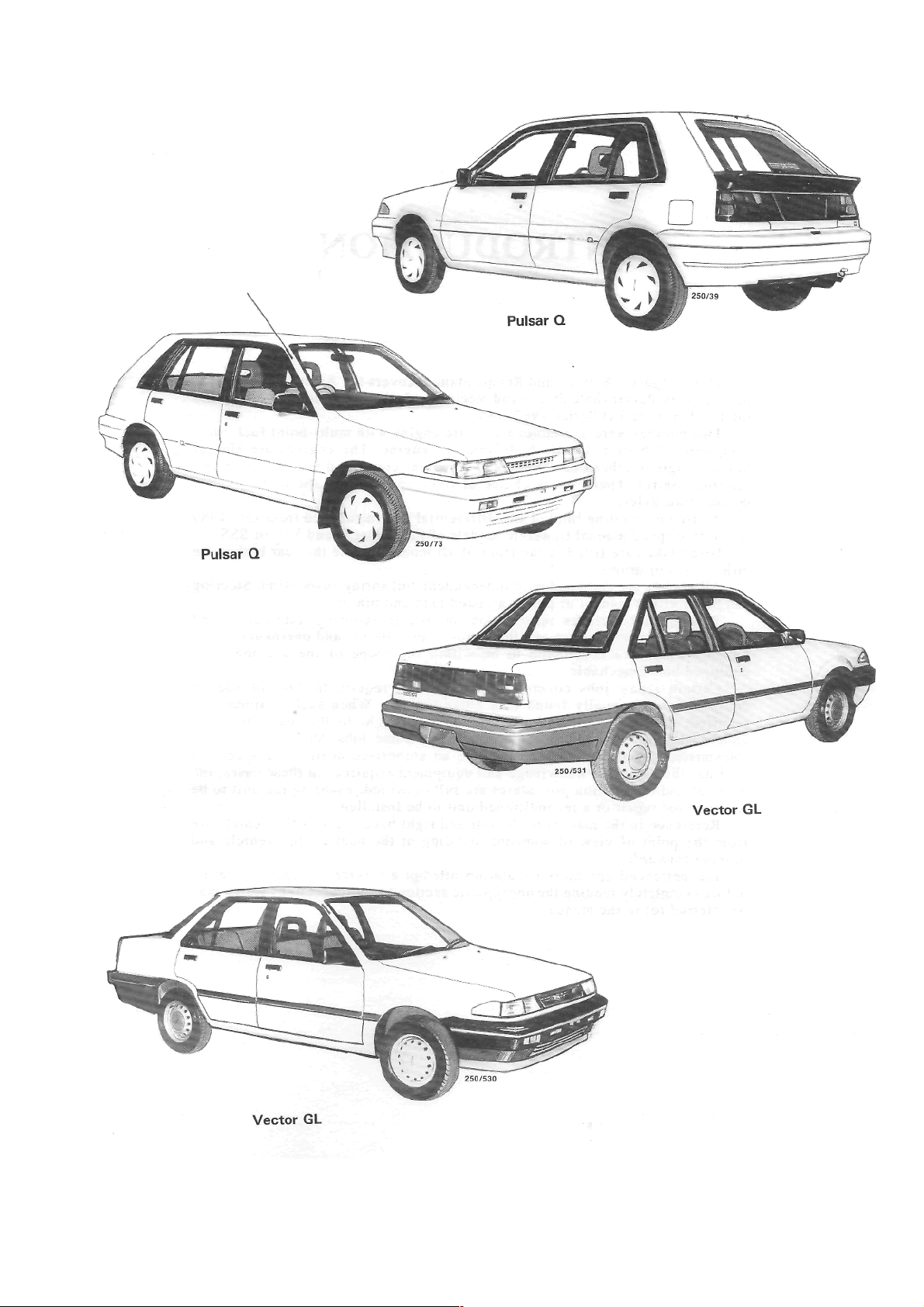
INTRODUCTION
This Service and Repair Manual covers the Australian manufac-
tured Nissan Pulsar (hatchback) and Vector (sedan) N13 Series 1
the Holden Astra LD Series 1987 - 89.
Two engines were available: a 1.8 l it er engine with multi-point fuel injection, and a 1.6 liter throttle body injected engine. The engines are similar
having single overhead camshafts and computer controlled fuel injection and
ignition control. There was a choice of three speed automatic or five speed
manual transaxles.
A viscous coupling limited sli p differential was introduced from July 1989
to the five speed manual transaxle models of the Pulsar Q and Vector SSS.
Disc brakes are fitted at the front of al l models, while the rear brakes are
either discs or drums.
All models are equipped with independent coil spring suspension. Steering
can be by either manual or power assisted rack and pinion.
This manual includes information on trouble shooting, lubrication and
maintenance, specifications and the removal, installation and overhaul of components which are considered to be within the scope of the average, well
equipped home mechanic.
Certain repair jobs covered in this manual require the use of special
equipment not normally found in a home tool kit. When such equipment is
required, the equipment and its function is brought to the users attention
underneath the heading for that component. Some jobs, such as automatic
transmission overhaul, should he left to an authorized dealer or a specialist
who has the extensive knowledge and equipment required. In these cases, the
removal and installation procedures are fully covered, enabling the unit to be
removed for repair or a reconditioned unit to be installed.
Reference in the manual to the left and right hand sides of the vehicle are
from the point of view of someone standing at the back of the vehicle and
looking forward.
Inexperienced operators should not attempt a service or repair operation
before completely reading the appropriate section (or other sections which may
be referred to) in the manual.
(
J87 - 91 and
Page 4
Page 5
VEHICLE IDENTIFICATION AND
GENERAL SPECIFICATIONS
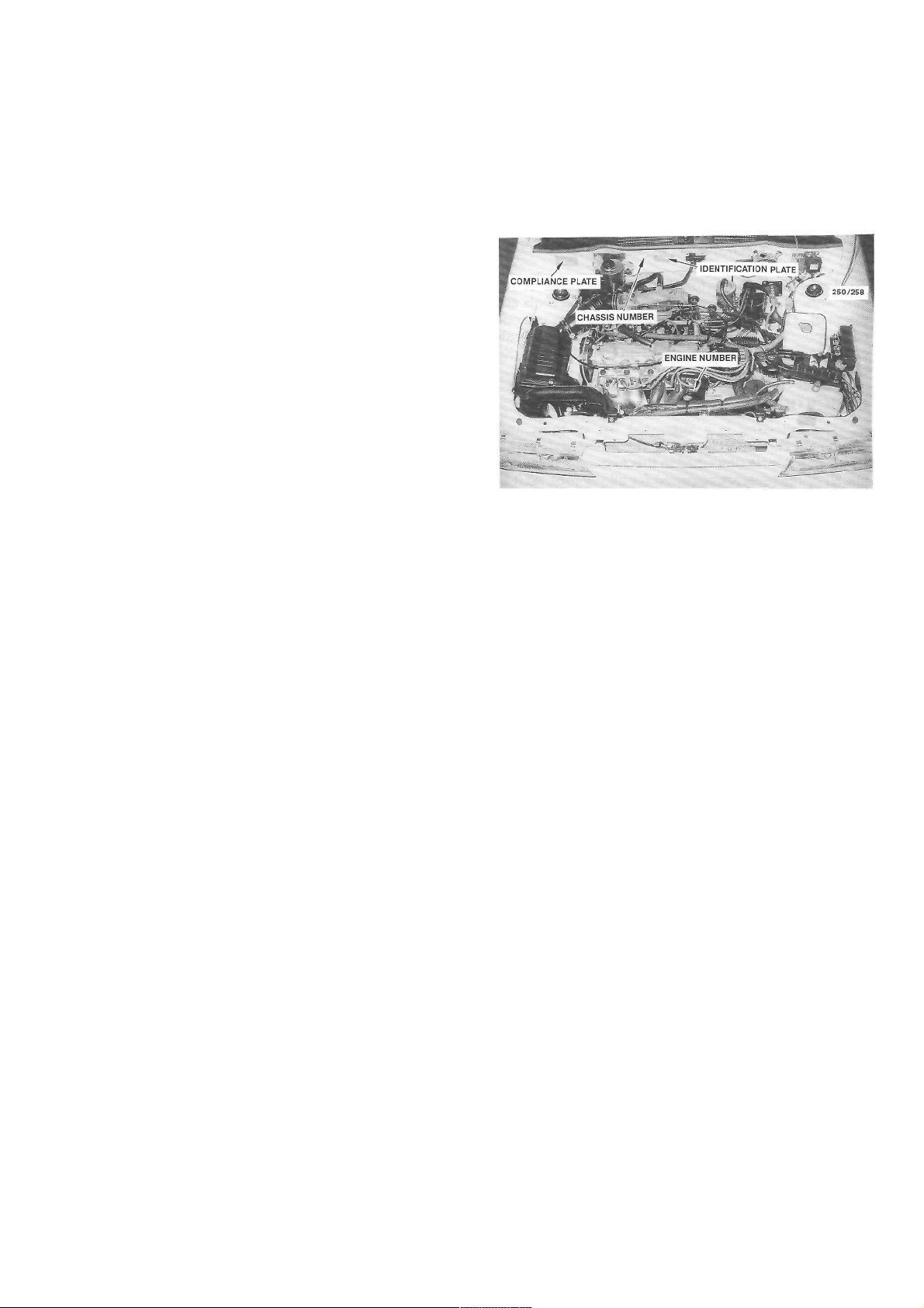
1. VEHICLE IDENTIFICATION
When purchasing spare parts or when
registering
or insuring a vehicle, it may be necessary to quote
various vehicle identification codes. The location of
these codes are as follows:
The Engine Number is stamped on the front
face
of the engine block below No. 4 spark plug.
The Chassis Number is stamped on the bulkhead
above and to the right of the brake booster.
The Vehicle Identification Plate is located on the
bulkhead to the left of the MAP sensor and contains
codings relating to body style, engine capacity,
model,
transaxle type, engine number, paint, trim and build
date.
The Compliance Plate contains information on
the vehicle make, model, month and year of manufacture, chassis number, seating, capacity and the
Australian Design Rules (ADR) with which the vehicle complies. This plate is affixed to the bulkhead
above and to the left of the brake booster.
The Tire Placard, which is located on the inside
of the glove compartment, contains information
on
the tire size, rim size, tire pressure and load ratings.
2. GENERAL VEHICLE SPECIFICATIONS
Length:
Pulsar...................................................4 030 mm
Astra hatchback ..................................4 035 mm
Vector ..................................................4215 mm
Astra sedan..........................................4 255 mm
Width:
Nissan .................................................. 1 640 mm
Holden ................................................. 1 655 mm
Height ........................................................ 1 380 mm
Wheelbase..................................................2 430 mm
Wheel track:
Front .................................................... 1 435 mm
Rear ..................................................... I 430 mm
View of the engine compartment showing the location
of various vehicle identification information.
Minimum ground clearance:
Nissan.................................................... 128 mm
Holden................................................... 110 mm
Turning circle kerb to kerb .......................... 10.8 m
Fuel tank capacity:
Nissan.................................................... 47 liters
Holden................................................... 50 liters
Towing capacity:
Without trailer brakes............................ 400 kg
With trailer brakes................................. 900 kg
*Fuel consumption:
L/100km L/100km
(City) (Highway)
Manual transaxle 8.5 6.6
Automatic transaxle 9.0 7.2
*The fuel consumption information is based on
tests made according to Australian Standard 2877.
The actual fuel consumption will depend on many
factors including driving habits, vehicle condition
and equipment and the prevailing conditions.
Page 6
GENERAL INFORMATION
1. TOOLS AND EQUIPMENT
To successfully perform any maintenance or repair work on a motor vehicle, suitable hand tools are
essential. The use of tools for other than their intended purpose or the use of incorrectly fitting tools can
cause damage to the component and/or injury lo the
operator.
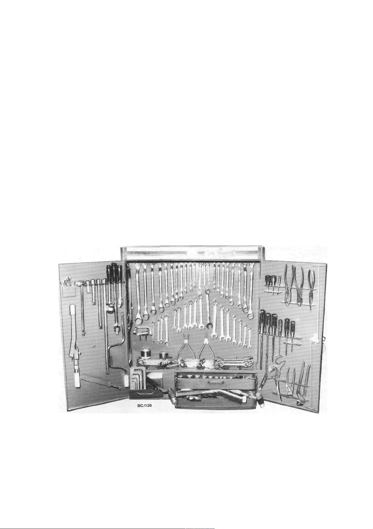
BASIC TOOL KIT
equipment for the majority of the maintenance and
repair procedures described in this manual. Of course,
not all of the tools are required for all the jobs, so it is
wise to purchase tools on an 'as needed' basis.
The following is a suggested list of tools and
Set of open ended spanners.
Set of ring spanners.
Set of socket spanners.
Spark plug spanner.
Assorted bladed screwdrivers.
Assorted Philips screwdrivers.
Assorted pliers — combination, long nose, multigrip, vice grip, snap ring (internal and external).
Assorted adjustable spanners.
Ball pein hammer.
Cold chisels.
Pin punches and centre punch.
Assorted files.
Scraper.
Feeler gauges.
Torque wrench.
Hydraulic jack.
Chassis stands.
Car ramps.
Grease gun.
Oil can.
Oil gun.
Oil filter removal tool.
Funnel.
Containers for draining oil and washing components.
A comprehensive tool kit showing a wide range of general hand tools.
Page 7
General Information
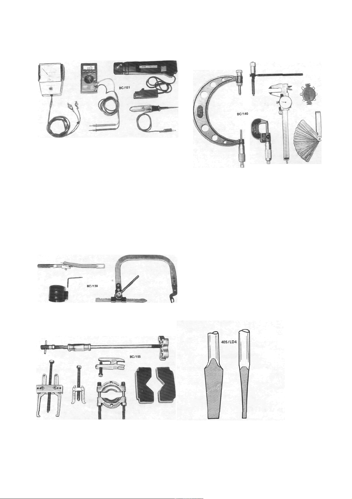
Assorted test equipment — dwell tachometer, digital
multimeter, timing light and test lamp.
Inspection lamp.
Test lamp.
Tachometer.
Timing light.
Digital multimeter.
Piston ring compressor.
Valve spring compressor.
Micrometer — inside, outside, multi range.
Vernier calipers.
Assorted pullers.
When purchasing tools, it is sound advice to select
the highest quality that can be afforded, as the
working life of cheaper tools is often very short.
Assorted measuring devices — inside and outside
micrometers, vernier calipers, wire gauges and feeler
Ensure that the tools are suitable for the system of
bolt and nut sizing on the vehicle. The range of
vehicles covered by this manual use metric sizes.
TOOL CARE
To ensure the longest possible life for hand tools,
it is important that time be spent maintaining them.
At the conclusion of each job. all tools used should
be washed thoroughly in kerosene or similar cleaning
solvent. Ensure that all dirt and grease is removed,
particularly from tools with moving parts such as
pliers and adjustable spanners. The tools should then
be wiped dry with a clean cloth.
Measuring devices should be given particular
attention as their accuracy can be affected if not
properly maintained. Feeler gauges should be kept
clean at all times and the blades should be wiped with
an oily cloth after use to prevent rusting.
gauges.
Tension wrench, piston ring compressor and valve
spring compressor.
Slide hammer, ball joint puller, assorted pullers and
press plates.
Views showing the correct tip profiles for a bladed
screwdriver. Bladed screwdrivers should not be
ground to a sharp point.
Page 8
10
General Information
If tools are to be stored for any length of time, it is
good policy to wipe them with an oily cloth.
Bladed screwdrivers should be checked for damage to the tip. If necessary, the tip can be returned to
its original profile by careful grinding. Do not grind
screwdriver tips to a sharp point.
Hammer heads should be secure on their handles
and should be regularly checked for cracking or other
damage.
Chisels and punches should be checked for damage or 'mushrooming' of the head. Any faults should
be rectified by grinding.
Hydraulic jacks should be regularly checked for
fluid leaks. Chassis stands and car ramps should be
checked for damage and cracks. Any equipment that
is suspect should not be used.
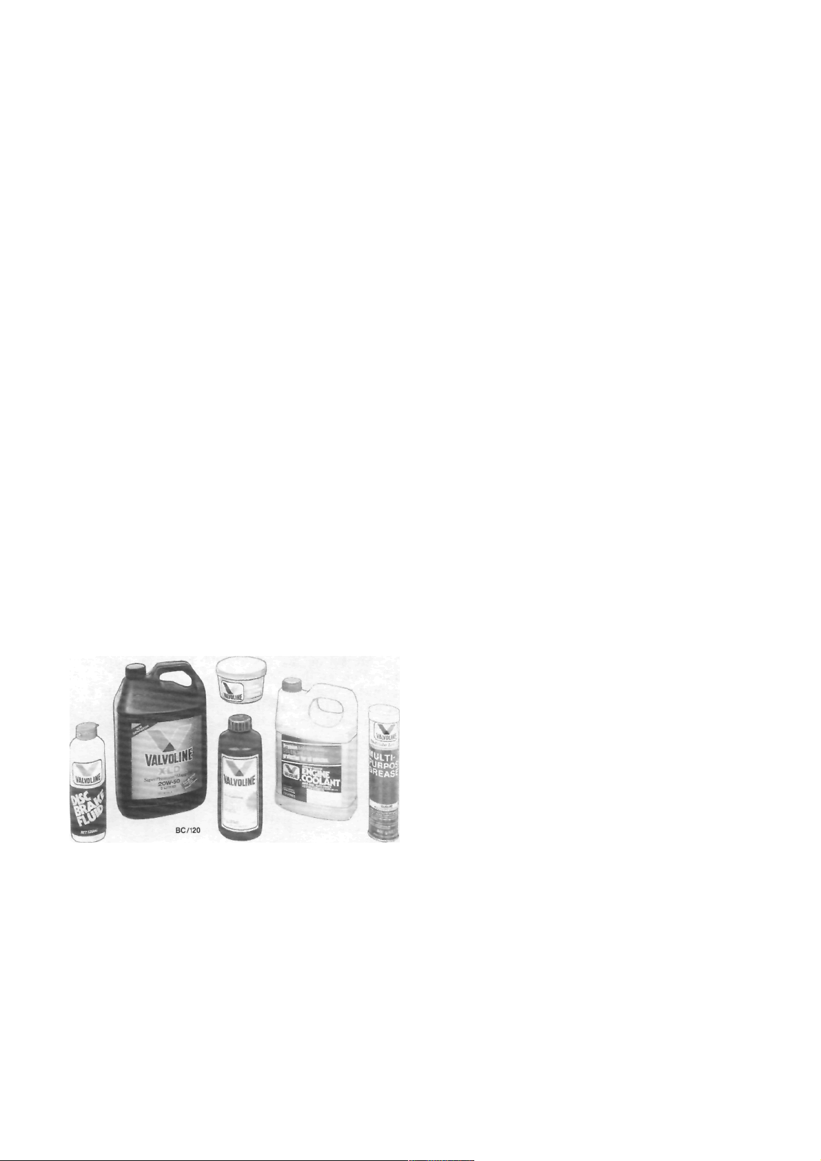
STORES
For routine maintenance, stores of automotive
oils, greases and additives should be kept on hand.
The following is a suggested list.
Engine oil.
Brake fluid.
Manual transmission or automatic transmission
oil — automatic transmission oil is also used in
the power steering system.
Rear axle oil.
Cooling system corrosion inhibitor/antifreeze.
Chassis grease.
High melting point grease, for hub bearings etc.
Penetrating oil or spray.
Kerosene or similar cleaning solvent.
Methylated spirits.
Oils and greases are available in handy pack size for
do-it-yourself lube jobs.
2. SAFETY
PERSONAL SAFETY
Safety when working on a motor vehicle is basically a matter of commonsense. Some safety precautions
to prevent personal injuries are as follows.
Raising a Vehicle
Always jack a vehicle on firm, level ground and at
the specified jacking points. Ensure that the wheels
remaining on the ground are fully chocked.
After raising the vehicle, place chassis stands
underneath and allow the weight of the vehicle to rest
on them. Do not use bricks, blocks of wood or similar
material.
NOTE: Never work under a vehicle which is
only supported by a jack.
Electrical System
Always disconnect the negative battery terminal
when working on any electrical components. Avoid
wearing metal watches, rings and chains which may
short across live terminals.
As battery gases are explosive, keep naked flames
and sparks clear of the work area. When connecting
and disconnecting jumper leads, use extreme caution
to avoid sparking.
Electronic Ignition Systems
Electronic ignition systems produce dangerous
high tension voltages in both the primary and secondary circuits which can be fatal. Exercise extreme
caution when working on or near any ignition system
components. Do not disconnect high tension leads
while the engine is running.
Work Area
Do not run the engine in a confined space. Ensure
that the work area is adequately ventilated.
Spilt oil or water should be cleaned immediately
to avoid the possibility of slipping.
Fuel System
Always disconnect the negative battery terminal
when working on any fuel components. Do not smoke.
Keep naked flames and sparks clear of the work area.
Do not siphon fuel using the mouth. Use a hand
pump or suitable siphon.
Do not attempt to repair a fuel tank by welding it.
This is an extremely hazardous procedure and should
be entrusted to a specialist.
Cooling System
To avoid scalding, use caution when releasing the
radiator cap on an engine which is at normal operating
temperature. Turn the cap anti-clockwise to the first
stop and allow any pressure in the system to release.
When the pressure is released, remove the cap from
the radiator.
Brakes
As asbestos is used in some brake lining material,
avoid inhaling brake dust. Do not use compressed air
to remove the dust. Gentle brushing with a small
brush or using a vacuum cleaner with a hose attachment are the safest methods of cleaning the brakes.
The above precautions also apply to the clutch plate
lining material.
Page 9
General Information
11
Lifting Equipment
When using lifting equipment to lift heavy components such as the engine and/or transmission, use
metal slings or chain in preference to rope. If rope
must be used, ensure that it is not placed against sharp
edges on the component.
Automotive Lubricants and Solvents
Avoid prolonged skin contact with oils, greases
and solvents as some can cause skin irritations and
dermatitis.
Exercise caution when using cleaning solvents as
many are inflammable. Do not smoke. Keep naked
flames and sparks clear of the work area.
Compressed Air
Never point an air hose at another person or allow
compressed air to blow onto your skin. High pressure
air forced against the skin can enter the bloodstream
and prove fatal.
Suspension and Steering Components
Damaged suspension and steering components
should not be welded. Many of these components are
fabricated from toughened metals. If welded they may
lose their strength or become brittle. Damaged components should be renewed.
Air Conditioning
Avoid disconnecting air conditioning hoses as
escaping refrigerant can cause frostbite. The refrigerant is highly flammable and when burnt, a poisonous
gas is produced.
VEHICLE SAFETY
To prevent damage to the vehicle during servicing
or repair work, note the following precautions.
Brake Fluid
If spilt on the vehicle paintwork, brake fluid
should be immediately washed away with clean water
and allowed to dry naturally, not wiped with a cloth.
Catalytic Converter
The following should be observed to prevent
damage to the catalytic converter:
Do not operate the vehicle on leaded fuel.
Do not push or tow start the vehicle.
Do not allow the engine to idle for prolonged
periods.
Do not switch the ignition off while the vehicle is
in motion and the transmission is in gear.
Do not 'prime' the engine by pouring fuel into the
inlet manifold.
Do not operate the vehicle if the engine is
misfiring.
Avoid running the vehicle out of fuel.
Ensure that the engine oil is formulated to contain
low phosphorus levels.
Electronic Components
The electronic components of the ignition and
fuel injection systems can be damaged by the use of
incorrect testing equipment.
It is essential in all tests where voltage or resistance is to be measured that a digital display multimeter with a minimum 10 megohm input impedance
be used.
Some types of tachometers, timing lights and
ignition system analyzers are not compatible with
certain engine electronic systems. It is therefore
recommended that the manufacturer of the test equipment be consulted before using the equipment.
Jump starting, or being jump started by another
vehicle can cause damage to the electronic components of the vehicle. Refer to the Roadside Trouble
shooting section for the correct jump starting procedure.
3. GENERAL REPAIR PROCEDURES
SEIZED FASTENERS
Seized bolts, nuts or screws should first have a
liberal amount of penetrating oil applied. The fastener
should be left for a period of time to allow the oil to
penetrate and soften the corrosion which is causing
the binding.
Often, a sharp hammer blow to the head of the
fastener can dislodge the corrosion and permit it to be
loosened.
An impact driver, which can be fitted with a
socket or screwdriver bit, can be used to loosen a
seized fastener.
Another method is to heat the component in
which the fastener is seized. However, extreme caution should be exercised when heating aluminum
alloy components as the melting point is much lower
than that of steel.
If the above methods fail to free a seized nut,
carefully hacksaw through one side of the nut until it
can be split. Care should be taken that the threads of
the bolt or stud are not damaged.
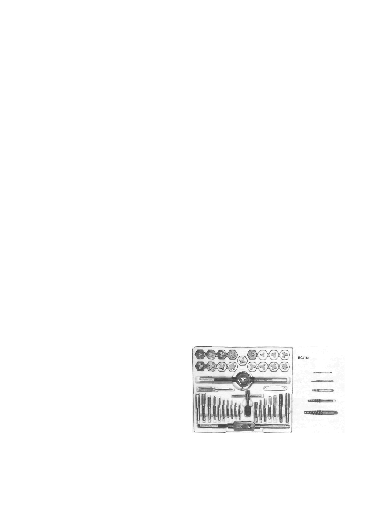
Should a bolt or stud break below the surface of
the component, it will be necessary to use a screw
extractor to remove the remaining part. Follow the
screw extractor manufacturers instructions.
Tap and die set and assorted screw extractors.
Page 10
12
General Information
Damaged threads can be repaired using a die nut
on studs and bolts, and a tap on nuts and threaded
holes in castings. If the threads of a threaded hole are
damaged beyond repair, it will be necessary to drill
and tap the hole to a larger size. Alternatively, a
Helicoil insert can be used to Testore the hole to the
original thread size.
STUDS
The simplest method for removing studs is to lock
two nuts together on the threaded section. The stud
should then be able to be removed by applying an
unscrewing action to the lower nut.
Alternatively, there are various makes of stud
extracting tools available.
similar levers between the components in an attempt
to lever them apart. This can cause severe damage to
the sealing surfaces, particularly if the components are
made of alloy compounds.
The components can be separated by tapping
along the joint with a soft faced hammer or piece of
wood. Before installing a new gasket, the mating
surfaces should be cleaned of all traces of old gasket
material and sealant.
Check that the new gasket is correct by comparing
the bolt holes and passages on the component face
with the openings in the gasket.
Cork and paper gaskets which have been stored
for some time may suffer from shrinkage. This can be
rectified by soaking the gasket in water.
BEARINGS AND BUSHES
If the correct equipment is not available when
removing and installing bearings and bushes, it is
often possible to improvise.
Bearings can often be removed from shafts by
tapping alternately on opposite sides with a hammer
and drift.
Using two nuts locked together to remove a stud.
OIL SEALS
Oil seals can usually be removed by levering out
with a flat screwdriver or other suitable lever. Care
should be taken not to damage the surface of the
component which the seal lip runs on.
Seals can also be removed by inserting a number
of self tapping screws into the seal body. The seal can
then be withdrawn using pliers gripping the self
tapping screws.
Always apply a smear of grease or oil to the seal lip
prior to installation to provide initial lubrication.
Unless otherwise stated, oil seals should always be
installed with the lip facing inwards or towards the
substance to be sealed. During installation, the seal lip
should be protected from damage from sharp components such as shaft splines by wrapping tape around
the sharp edges.
Install the new seal using a wooden block, or a
socket or length of tube of the appropriate diameter.
Ensure that the seal is installed squarely or distortion
and subsequent leakage may occur. If an installation
depth is not specified, the seal should be installed
flush with the component surface.
GASKETS
When separating mating components (i.e.
cylinder
head and cylinder block), do not insert screwdrivers or
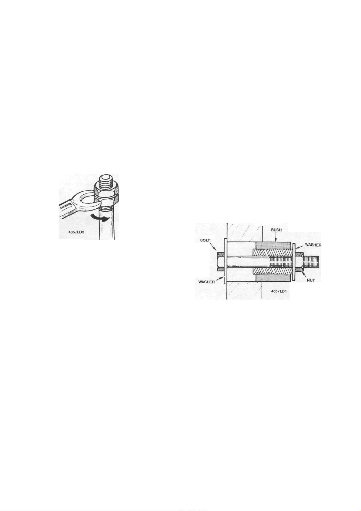
A simple bush installing tool using a bolt, nut and two
washers.
If a press is unavailable, bushes can be installed by
placing the bush and component between the jaws of a
vice and screwing the jaws together until the bush is
fully inserted. A vice can also be used to remove
bushes by using suitably sized spacers against either
vice jaw, one bearing on the bush and the other on the
component. This method can also be used with a G
clamp.
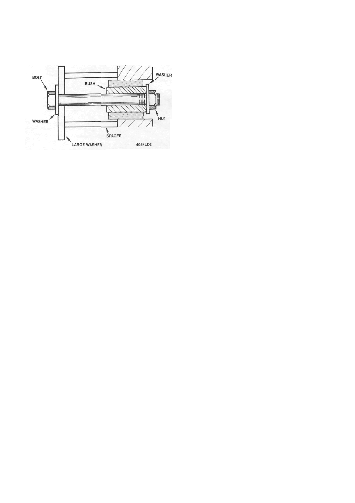
A simple removing and installing tool can be
made using a long bolt, large and small washers, a nut
and a tubular spacer. Refer to the illustrations for the
method and applications.
Rubber bushes and bushes in blind holes can be
removed using an expanding type masonry bolt
(Rawlbolt Loxin). Install a neat fitting masonry bolt to
the bush. Install and tighten the bolt until it grips the
bush. The bolt and bush can then be removed using a
slide hammer or levers.
Page 11
General Information
13
A simple bush removing tool using a bolt, nut, suitable
spacer and large and small washers.
Bushes in blind holes can also be removed using
hydraulic force. With the hole packed with grease,
insert a neat fitting drift and tap the drift into the hole.
The pressure of the grease on the rear of the bush
should force it from the hole.
ROTATING THE CRANKSHAFT
There are many occasions when it is necessary to
rotate the crankshaft to a certain position. These
include timing and valve adjustment and checking
valve timing.
To make the engine easier to rotate, remove the
spark plugs. This will relieve compression pressure.
The simplest method is to use a socket or ring
spanner on the crankshaft pulley nut and turn the
engine in the normal direction of rotation.
On vehicles with manual transmission, the engine
can be turned by selecting top gear and rolling the
vehicle forward. A variation of this method is to raise
one of the driving wheels and, with top gear selected,
rotate the driving wheel in a forward direction to turn
the engine.
Alternatively, the engine can be brought to the
desired position by briefly actuating the starter motor.
Page 12
14
LUBRICATION AND MAINTENANCE
SPECIFICATIONS
CAPACITY AND GRADE
Engine:
Lubricant........................................... 15W-50 SF
Sump capacity including filter ........... 3.3 liters
Cooling system capacity............................ 6.0 liters
Manual transaxle:
Lubricant.......................................80W-90 GL-4
Capacity ............................................... 2.7 liters
Automatic transaxle:
Lubricant.............................................. Dexron II
Capacity ............................................... 6.0 liters
Power steering:
Lubricant.............................................. Dexron II
Capacity ............................................... 1.0 liters
Manual steering lubricant........ Castrol EPLl grease
Brake fluid type ................................................ Dot 4
1. HOW TO GREASE AND OIL CHANGE
(1) Run the front of the vehicle onto car ramps
and stop the engine. Chock the front wheels.
(2) Raise the rear of the vehicle and place
chassis stands under the rear jacking points.
NOTE: It is best if the vehicle is kept as level
as possible to avoid false readings when
checking the lubricant levels.
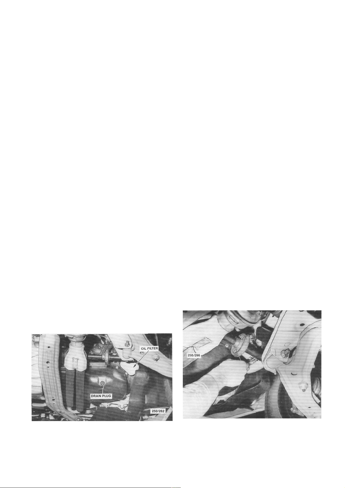
(3) Clean around the engine sump drain plug.
(4) Place a drain tin under the engine sump,
remove the engine sump drain plug and allow the
engine sump to completely drain.
NOTE: It is best to drain the engine sump
with the oil at operating temperature. However, if the oil is hot take care to avoid
scalding.
(5) Check that the sealing gasket on the sump
plug is in a serviceable condition.
(6) When the engine sump has completely
drained, install and firmly tighten the sump drain plug.
Wipe around the plug after installation.
(7) Place the drain tin under the oil filler,
remove the oil filter using a filter removal tool and
allow the residual engine oil to drain. Smear the
scaling ring of the new filter with engine oil and
lighten the filter by hand as per the instructions
supplied with the new filter.
NOTE: Before installing the new filter, ensure that the sealing gasket from the old
filter has not adhered to the filter sealing
surface on the engine.
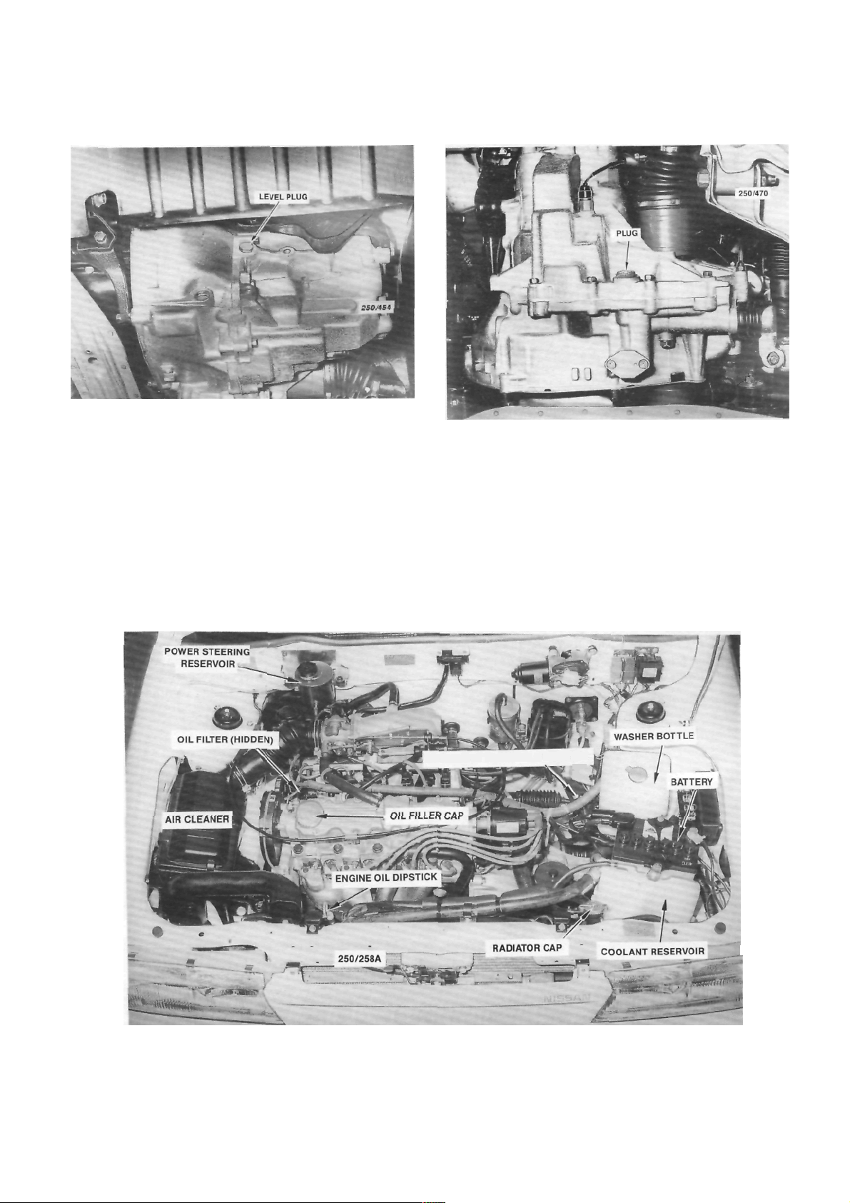
(8) Rem o v e t he level check i n g p lug from the
Location of the engine sump drain plug.
Removing the engine oil filter using a filter removal tool.
Page 13
Lubrication and Maintenance
Location of the manual transaxle level plug.
manual transaxle. Using a finger, check that the oil is
level with the bottom of the plug hole. Overfilled units
should be drained to the correct level.
If the oil level is low, use an oil gun to fill the
transaxle to the correct level.
When satisfied that the oil level is correct, install
the plug and tighten firmly. Wipe around the plug
after installation.
NOTE: On automatic transaxle vehicles,
refer to the Automatic Transaxle section for
the checking and topping up procedure.
Location of the manual transaxle drain plug.
(9) Using a funnel, fill the engine with the
specified amount and grade of engine oil. start the
engine and run it for a few minutes. Ensure that the
oil light goes out. Stop the engine, wait for a few
minutes and check the engine oil on the dipstick. If
necessary add oil to bring the level to the full mark on
the dipstick.
NOTE: To prevent overfilling the engine
initially, it is good policy not to pour all the
15
AUTOMATIC TRANSAXLE DIPSTICK
Underbonnet view of the 1.8 liter engine. Automatic transaxle model.
r
Page 14
16
Lubrication and Maintenance
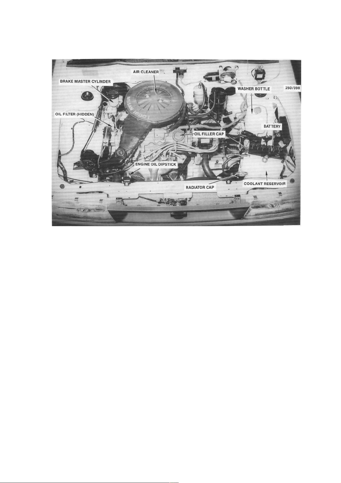
Underbonnet view of the 1.6 liter engine. Manual transaxle model.
oil into the engine in one go as sometimes
the amounts specified are only approximate.
If is best to hold back at least half a liter and
top up the level after the engine has been run
for a few minutes.
(10) Check thoroughly for oil leaks at the engine
sump drain plug and oil filter if a new filter was
installed.
(11) Referring to the service schedule, lubricate
and check all other items which coincide with the
grease and oil change intervals.
(12) Lower the vehicle to the ground.
Page 15

Lubrication and Maintenance 17
2. SERVICE SCHEDULE
This Section Removed
Page 16

18
Lubrication and Maintenance
This Section Removed
Page 17

Lubrication and Maintenance
19
This Section Removed
Page 18

20
Lubrication and Maintenance
This Section Removed
Page 19
WHEELS AND TYRES
SPECIFICATIONS
TYRES PRESSURES
Front:
Normal load ............................................ 200 kPa
Heavy load or high speed ......................230 kPa
Rear:
Normal load ............................................ 180 kPa
Heavy load or high speed ...................... 210 kPa
NOTE: The above pressures are measured
cold and are meant as a guide only. Always
refer to the tire placard positioned on the
inside of the glove compartment lid and the
tire manufacturers recommendations first.
TORQUE WRENCH SETTINGS
Wheel nut torque .............................................98 Nm
1. HOW TO CHANGE A ROAD WHEEL
(4) Apply the handbrake firmly and chock the
front and rear of the wheel diagonally opposite the
wheel being changed.
(5) Remove the spare wheel, tool kit and jack
located in the luggage compartment.
(6) On vehicles equipped with full wheel covers,
remove the trim from the wheel.
(7) Using the wheel spanner, loosen the wheel
nuts progressively in a diagonal sequence half a turn.
(8) Position the jack under the jacking point
closest to the wheel being removed and raise the jack
until the head of the jack contacts the jacking point.
(9) Raise the vehicle slightly and check that the
jack is stable and vertical.
(1) Ensure that the vehicle is on level firm
ground and clear of any passing traffic.
(2) If necessary, switch on the hazard
flashers.
(3) Switch off the engine and place the transaxle
in the (P) Park position on automatic transaxle
models or in reverse gear on manual transaxle models.
Chock the front and rear of the wheel diagonally
opposite the wheel being changed.
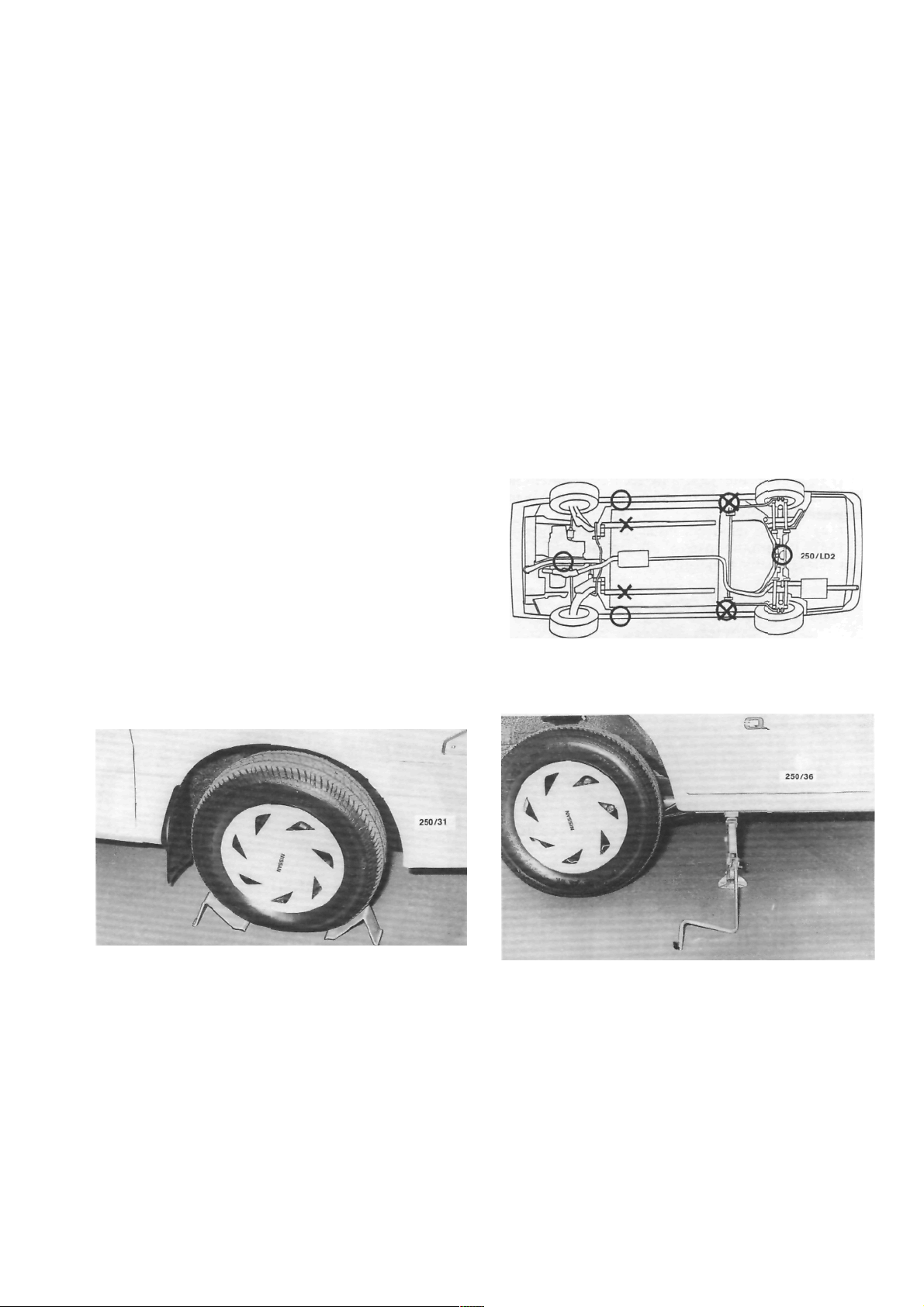
Underbody view showing the jacking and supporting
points. O indicates the jacking points and X indicates
the supporting points.
View of the jack correctly installed to the rear jacking
point.
Page 20
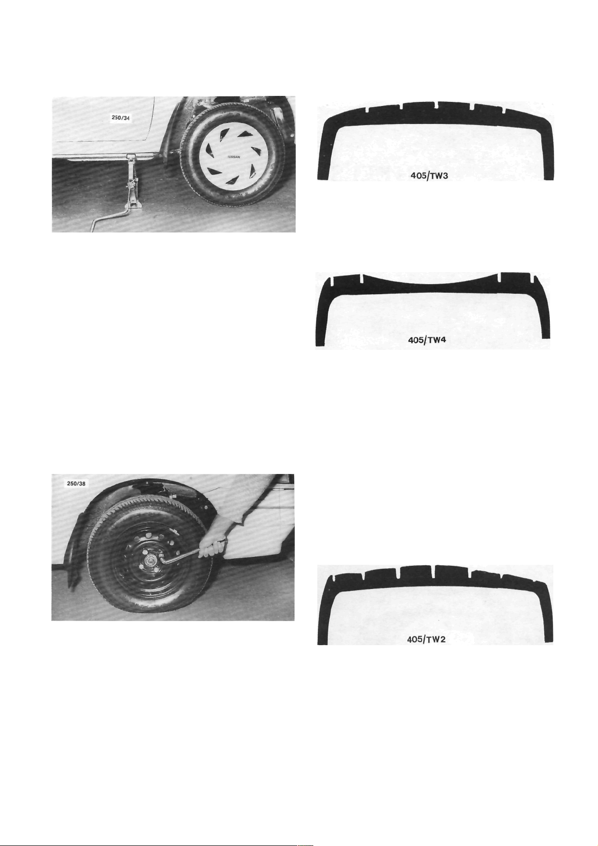
22
View of the jack correctly installed to the front jacking
point
.
Wheels and Tires
(10) Continue to raise the jack until the tire
clears the ground sufficiently to allow the spare wheel
to be installed.
(11) Remove the wheel nuts and lift the wheel
off the hub.
NOTE: Under no circumstances get under
the vehicle while the jack is the only means
of support.
(12) Install the spare wheel and install the wheel
nuts with the chamfered ends contacting the wheels.
Tighten the wheel nuts as much as possible by hand.
(13) Lower the jack and securely tighten the
wheel nuts progressively in a diagonal sequence using
the wheel spanner.
(14) Where removed, install the wheel cover.
(15) Return the spare wheel, jack and tool kit to
their relevant storage positions.
ABNORMAL WEAR ON CENTRE OF TREAD
(1) Over inflation of tires: Check and reduce to
the recommended pressure.
ABNORMAL WEAR ON INSIDE OF TREAD
(1) Excessive negative camber angle: Check the
wheel alignment.
(2) Sagging coil springs: Check and renew the
coil springs as a pair.
(3) Loose or worn hub bearing assembly: Check
and renew the hub bearing assembly.
(4) Bent, loose or worn suspension components:
Check and renew any faulty components.
Tighten the wheel nuts in a diagonal sequence using
the wheel spanner.
2. TYRE WEAR TROUBLE SHOOTING
ABNORMAL WEAR ON BOTH SIDES OF
TREAD
(1) Under inflation of tires: Check and inflate to
the recommended pressure.
(2) Overloading: Reduce the maximum loading.
ABNORMAL WEAR ON OUTSIDE OF TREAD
(1) Excessive positive camber: Check the front
wheel alignment.
(2) Excessive speed when cornering: Revise driv-
ing habits.
(3) Bent, loose or worn suspension components:
Check and renew any faulty components.
FLAT SPOTS ON TREAD OR IRREGULAR
WEAR
(1) Static or dynamic unbalance of the wheel
and tire assembly: Check the balance of the wheel and
tire assembly.
(2) Lateral run out of the wheel: Check and (rue
up or renew the wheel.
Page 21
(3) Excessive play in the front suspension ball
joints: Check and renew the ball joints.
(4) Excessive play in the hub bearing assembly:
Check and renew the hub bearing assembly.
Wheels and Tires
23
WORN SPOTS ON CENTRE OF TREAD
(1) Static unbalance of the wheel and tire asem-
bly: Check the balance of the wheel and tire assembly
(2) Radial run out (eccentricity) of the wheel:
Check and renew the wheel.
FEATHERED EDGES ON TREAD PATTERN
(1) Excessive speed when cornering: Revise driv-
ing habits.
(2) Excessive toe-in or toe-out: Check and adjust
the wheel alignment.
(3) Bent, loose or worn suspension components:
Check and renew any faulty components.
NOTE: To preserve tire life it is good policy
to periodically have the front wheel balanced
and the steering geometry checked on a
reliable wheel alignment machine.
Under no circumstances mix radial ply
and conventional ply tires. Install only tires
of the same construction to all four wheels.
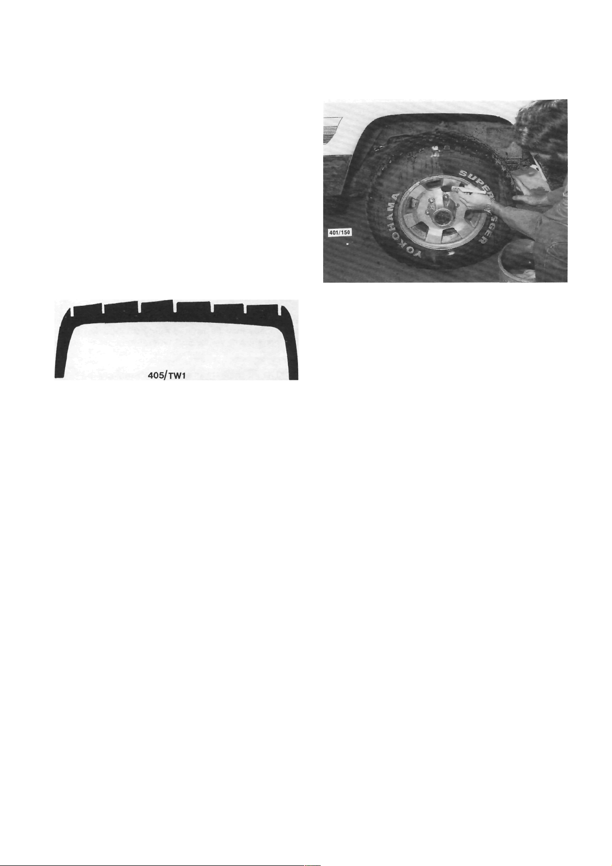
3. CARE AND MAINTENANCE
STEEL WHEELS
Steel wheels should be regularly cleaned of all
foreign matter, such as dirt and mud. If foreign matter
is allowed to build up it will affect the balance of the
wheel and may cause vibrations and uneven tire wear.
If the paint has been chipped or scratched it should be
touched up as soon as possible to prevent rust.
Any minor damage to the wheel rim can usually
be repaired using a suitable hammer after the wheel
has been removed from the vehicle. However, any
major rim damage or buckling of the wheel will
necessitate the renewal of the wheel. It is good policy
to occasionally remove the wheels from the vehicle
and inspect them for damage, cracks or corrosion.
ALLOY WHEELS
Alloy wheels should be regularly cleaned of all
foreign matter such as dirt and mud. If foreign matter
Wheels should be cleaned regularly of dirt and mud.
is allowed to build up it will affect the balance of the
wheel and may cause vibrations and uneven tire wear.
The alloy wheels are coated with a clear protective
finish. Do not use abrasive cleaner, polishing compounds, steel wool etc. when cleaning the wheels. Only
mild soap and warm water are recommended. Alloy
wheels are particularly susceptible to corrosion damage particularly if exposed to salt water.
Alloy wheels being relatively soft in comparison to
steel are easily scuffed, however, this will not affect the
serviceability of the wheel. Where heavy damage has
been sustained to the wheel it should be renewed.
Buckling or cracking of an alloy wheel cannot be
repaired.
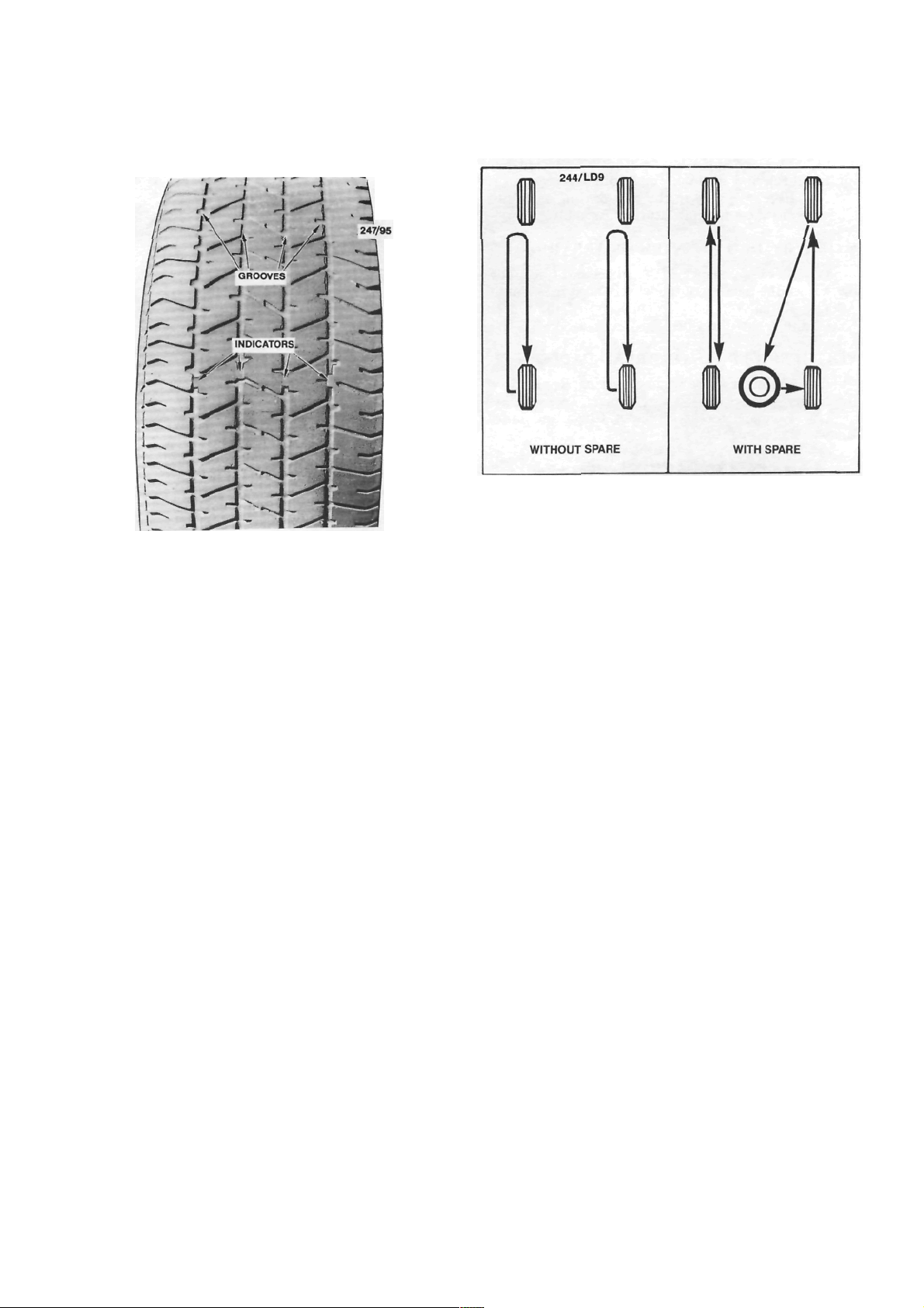
TYRES
The depth of the tire tread grooves should never
be allowed to be less than 1.5 mm before the tires are
renewed. The tires should also be renewed when any
damage, whether it be internal or external, is evident.
Minor punctures or leaks should be properly repaired.
Refer the tire to a tire specialist if there is any doubt
about the serviceability of the tire.
The tread, tread grooves and sidewalls should be
regularly inspected for foreign matter i.e. nails, stones
etc. Where foreign matter is detected it should be
removed from the tire and if necessary, the puncture
repaired.
The tire valves should always have the caps
installed, be regularly cleaned of dirt or dust and be
inspected for leakage and damage every time the tire
pressures are checked.
Regularly inspect the tread of the tires for signs of
uneven wear. If uneven wear is apparent, refer to the
heading Tire Wear Trouble Shooting in this section
for possible causes and cures. If the uneven tire wear
is noticed early enough, the cause correctly identified
and the necessary cure carried out, the life of the tire
should be extended.
Page 22
24
Wheels and Tires
When the tire tread groove depth is less than 1.5
mm, or when the tire is worn to the point where the
tire wear indicators are level with the tread surface,
To preserve tire life it is good policy to periodically have the front wheels balanced and the front end
alignment checked on a reliable wheel alignment
machine.
The wheel and tire assemblies may be rotated at
20 000 km if desired. Rotation of the wheels and tires
will increase the period between tire renewal. Radial
tires should not be cross changed, they should be
changed from front to rear on the same side.
the tire should be renewed.
Tire rotation diagram. If desired, the wheel and tire
assemblies may be rotated every 20 000 km in the
manner shown. Vector SSS tire rotation not to include
spare wheel.
The air pressure in the tire is probably the single
most important aspect of tire care. Too little or too
much pressure in the tire can cause rapid wear or
complete failure through overheating. Where possible
the tire pressures should be checked and adjusted
when the tires are cold.
As a rule, different tire types, tread patterns or
sizes should never be used on the vehicle at one time.
All the tires on the vehicles, including the spare
should be a matched set to prevent the vehicle
behaving erratically under certain conditions. Under
no circumstances mix radial ply and conventional ply
tires.
Page 23
25
ENGINE TUNE-UP
CAUTION: To prevent severe electrical shock, extreme care must be taken when
working on or near the electronic ignition system as dangerous high tension voltages
are produced in both the primary and secondary circuits. See the text for
precautionary notes.
1. TUNE-UP SPECIFICATIONS
Firing order................................................... 1 -3-4-2
Spark plugs:
Type ............................................. NGK BPR 6ES
Gap ...........................................................1.1 mm
Tightening torque...................................... 20 Nm
Ignition timing with diagnostic link
connector jumped...........................10 deg BTDC
Idle speed (ECU controlled):
Manual transaxle 1.8 liter............ 850 ± 50 rpm
Manual transaxle 1.6 liter............ 800 ± 50 rpm
Automatic transaxle
(Park or Neutral).......................... 825 ± 50 rpm
Drive belt deflection:
Alternator ........................................... 14-16 mm
Power steering pump......................... 14-16 mm
Air conditioner compressor .................. 9-11 mm
NOTE: When performing an engine tuneup, a/ways compare the above Specifications
with the emission control information label
inside the engine compartment.
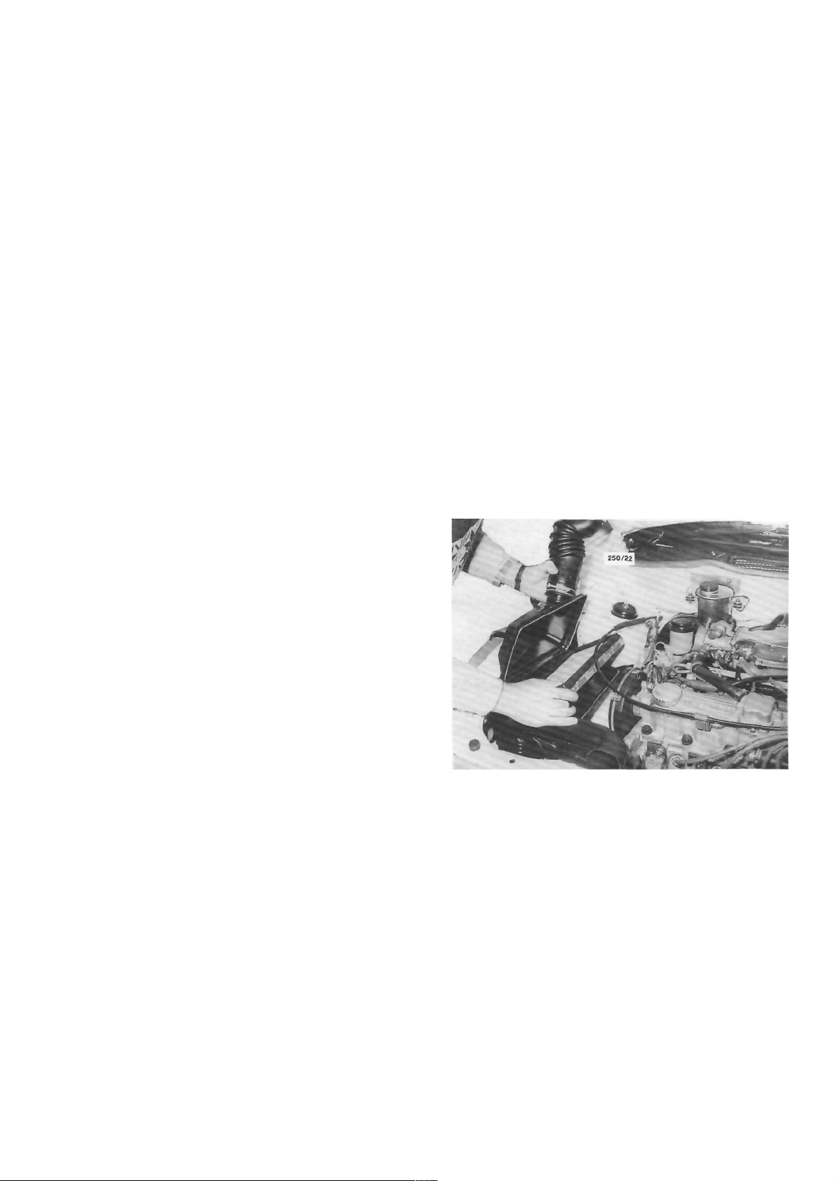
1.8 Liter Engine
(1) Release the clamp securing the air intake
hose to the throttle body and disconnect the throttle
cable from the support bracket.
(2) Release the clips retaining the upper air
cleaner housing to the lower air cleaner housing and
raise the upper housing while disconnecting the air
intake hose from the throttle body. Remove the air
cleaner element.
2. TUNE-UP OPERATIONS
Special Equipment Required:
To Test Compression — Compression gauge
TO SERVICE AIR CLEANER
The air cleaner is equipped with a paper element.
The element should be regularly inspected but should
not be cleaned in service.
The element should be renewed every 40 000 km.
This distance is only a guide for normal operating
conditions and should be reduced accordingly if the
vehicle is operating under extremely dusty conditions.
NOTE: Paper air cleaner elements should
not be washed in petrol or any other type of
cleaning solvent. If the element has been
washed in solvent or has become oil soaked,
it should be discarded and a new element
installed.
The air cleaner element should be renewed at 40 000
km intervals. 1.8 liter engine.
(3) Clean the inside of the air cleaner housing
using a damp rag to remove all traces of dust and
check the upper housing and air inlet hose for cracks
and air leaks. Renew if necessary.
(4) Install a new air cleaner element to the lower
housing ensuring that the element is correctly seated
around the edges.
(5) Install the upper housing and lock the clips,
securing it to the lower housing. Connect the air
intake hose to the throttle body and the throttle cable
to the support bracket. Tighten the hose clamp
securely.
(6) Start the engine and check the air cleaner
assembly for air leaks.
Page 24
26
Engine Tune-up
1.6 Liter Engine
(1) Remove the nuts and washers securing the
upper air cleaner housing to the lower air cleaner
housing and release the retaining clips.
(2) Remove the air cleaner element.
(3) Clean the inside of the air cleaner housing
using a damp rag to remove all traces of dust.
(4) Install a new air cleaner element ensuring that
the element is correctly seated around the edges.
(5) Install the upper housing and secure the
retaining clips. Tighten the retaining nuts securely.
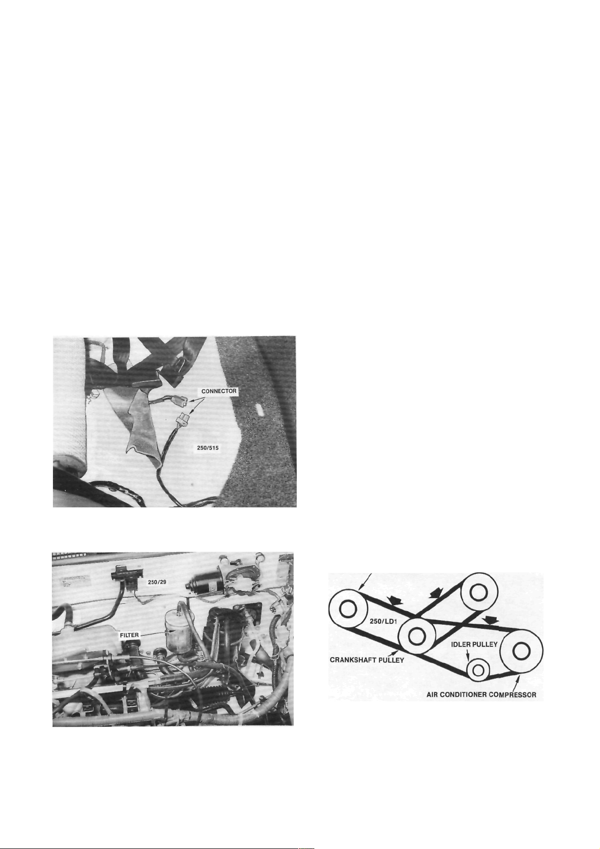
TO RENEW FUEL FILTER
filter should
The fuel
40 000 km.
be renewed every
(1) Depressurize the fuel system using the fol-
lowing procedure:
(a) Lift the front edge of the rear seat cushion
and remove the cushion from the vehicle.
When depressurizing the fuel system, remove the rear
seat cushion and disconnect the fuel pump wiring
connector.
(b) Disconnect the fuel pump wiring connector.
(c) Start and run the engine until it stalls.
Operate the starter motor for 10 seconds to ensure
that the fuel pressure has dissipated.
(2) Disconnect the negative battery terminal.
(3) Release the hose clamps and disconnect the
fuel hoses from the filter. Remove the filter from the
retaining clamp noting the direction of the arrow on
the filter body.
On some models it will be necessary to remove the
screw from the side of the clamp to allow the filler to
be removed.
Installation is a reversal of the removal procedure
with attention to the following points:
(1) Install the fuel filter with the arrow facing the
direction noted on removal, that is, in the direction of
fuel flow.
(2) Ensure that the hose clamps are tightened
securely.
(3) Connect the fuel pump wiring connector and
install the rear seat cushion.
(4) Start the engine and check for fuel leaks.
Rectify as necessary.
TO ADJUST DRIVE BELTS
It is essential that all drive belts are adjusted to
the correct tension to prevent slippage or premature
wear of the bearings in the alternator and, if equipped,
the power steering pump and air conditioner compressor.
(1) P u sh do w n on t h e dri v e belt w ith a 10 k g
force midway between the pulleys of the drive belt
concerned.
On models with air conditioning, push down on
the upper section of the drive belt between the
compressor and crankshaft pulleys.
If the drive belt deflection is not within Specifications it will require adjustment as follows.
(2) Loosen the alternator and, if equipped, the
power steering pump pivot and adjusting bolts and
ALTERNATOR
POWER STEERING PUMP
Installed view of the fuel filter. Note the direction of the
arrow on the filter prior to removal.
Illustration of the alternator, power steering pump and
air conditioner compressor drive belts. The arrows
indicate the deflection measuring points.
Page 25
Engine Tune-up
move the alternator or power steering pump as
required until the drive belt concerned has the
specified deflection.
On models with air conditioning, loosen the nut
in the centre of the idler pulley and turn the adjusting
bolt until the drive belt has the specified deflection.
(3) Tighten the alternator or power steering
pump bolts securely and check the belt tension.
On models with air conditioning, tighten the idler
pulley nut securely.
TO SERVICE SPARK PLUGS
The spark plugs should be renewed at intervals of
40 000 km.
Before removing the spark plugs ensure that the
area around each plug is clean to prevent foreign
matter entering the cylinder when the plugs are
removed.
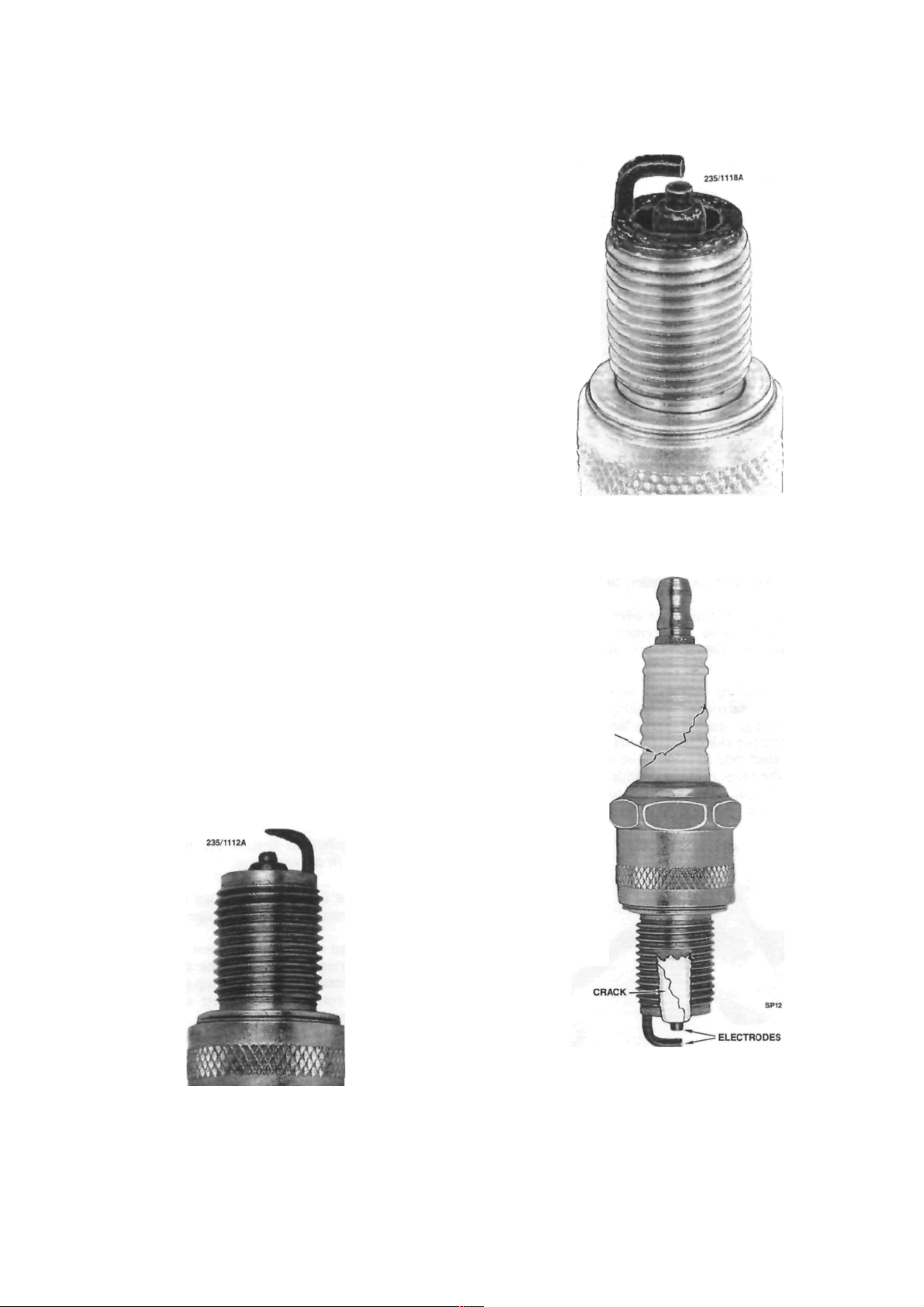
Spark plugs removed from an engine in good
mechanical condition should have a light powdery
deposit ranging from light brown to grayish tan in
color. After considerable service the electrodes will
show signs of wear or normal burning. Spark plugs
showing a thick black oily deposit indicate an engine
in poor mechanical condition or possibly, that a plug
with too low a heat range has been installed.
Spark plugs showing a white or yellowish deposit
indicate sustained high speed driving or possibly that
plugs with too high a heat range have been installed,
particularly when these deposits are accompanied by
blistering of the porcelain and burning of the electrodes.
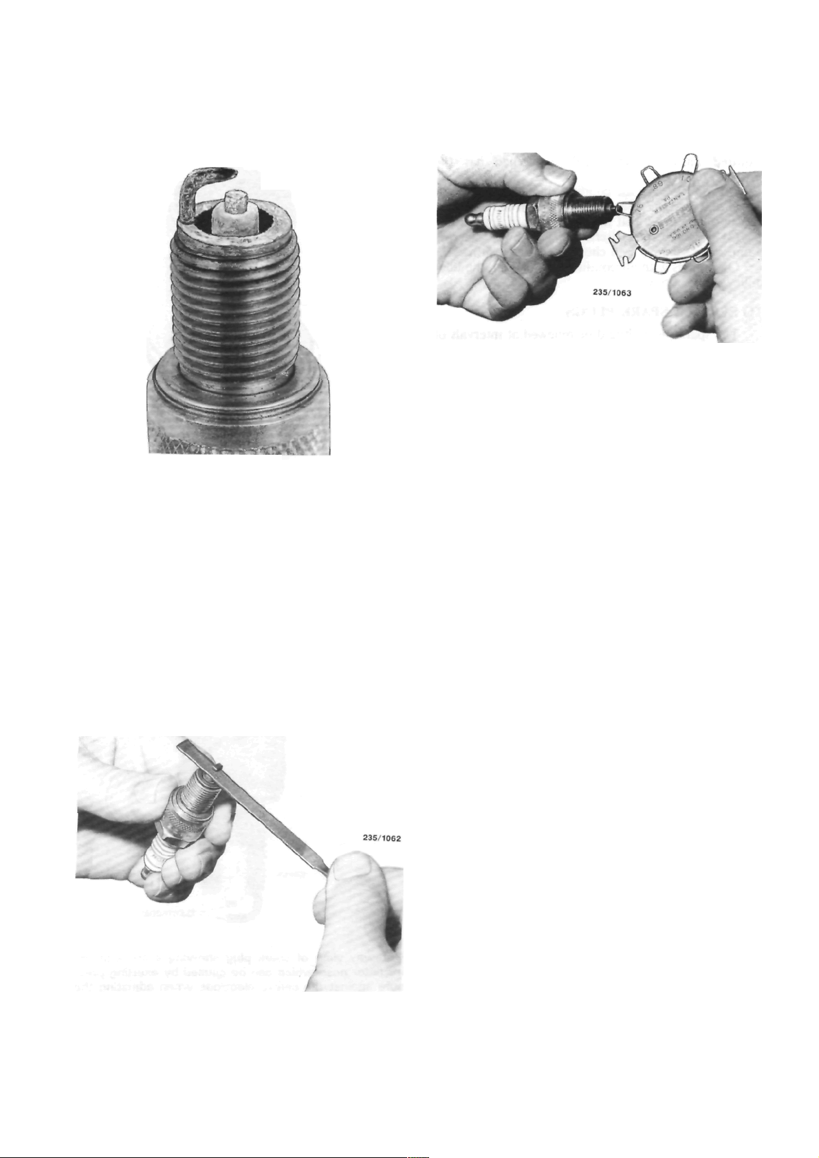
If the spark plugs are to be cleaned, use a
sandblasting machine and blow clean with compressed air. Ensure that all traces of abrasive grit are
removed from the spark plug threads and from the
well in the plug body. Carefully open the electrode gap
a little, by bending the side electrode, and lightly file
the electrodes flat with a points file.
27
Black damp deposits can be caused by excessive oil
consumption or incorrect plug type. Spark plugs in this
condition are usually not firing.
CRACK
When plug electrodes are eroded to this degree the
spark can be considered worn out and should be
renewed using a plug of the recommended heat range
.
Cutaway view of spark plug showing a crack in the
insulator nose which can be caused by exerting pressure against the centre electrode when adjusting the
gap. The other crack shown on the insulator is caused
by tilting the plug spanner.
Page 26
Engine Tune-up
Spark plug with burnt electrodes and white blistered
appearance, possibly due to incorrect plug type, loose
plug or motor running too hot.
NOTE: Never attempt to alter the electrode
gap by bending the centre electrode as
damage to the porcelain insulator will
result.
Before installing any spark plugs measure the gap
between the electrodes, preferably with clean wire
gauges. If wire gauges are unavailable, use clean feeler
gauges. Move the side electrode towards or away from
the centre electrode to obtain the correct gap-
Screw the plugs into the cylinder head ringer tight,
then use a torque wrench to tighten the plugs lo the
specified torque.
Checking the spark plug electrode gap with a wire
gauge.
NOTE: If a torque wrench is unavailable,
extreme care must be taken when tightening
the spark plugs as over tightening may lead
to stripping of the thread from the cylinder
head. If the plugs are tightened with the
fingers and then taken up an additional 1/4
of a turn with a spark plug wrench, they will
be tight enough.
TO TEST COMPRESSION
(1) With the engine at operating temperature.
disconnect the high tension leads from the spark
plugs.
(2) Ensure that the area around each spark plug
is clean to prevent foreign matter entering the cylinders and remove the spark plugs.
(3) Remove the fusible link that is positioned
third from the front of the fusible link connecting
block, located at the rear of the battery. Disconnect
the coil high tension lead from the coil.
NOTE: Failure to remove the fusible link
can result in an explosion.
Lightly file the plug electrodes flat with a points file
(4) Install a compression gauge to number one
spark hole according to the gauge manufacturers
instructions.
(5) Have an assistant fully open the throttle and
operate the starter switch to rotate the engine. Observe the compression gauge and stop the engine when
the gauge has reached the highest reading, usually
after 3 or 4 compression strokes.
(6) Record the reading and check the compres-
sion of the remaining cylinders in the same manner.
(7) Compare all the readings taken. Variation
between the highest and lowest reading cylinders
should not exceed 100 kPa.
(8) If a low reading is recorded on one or more
cylinders the trouble may be isolated as follows :
Page 27
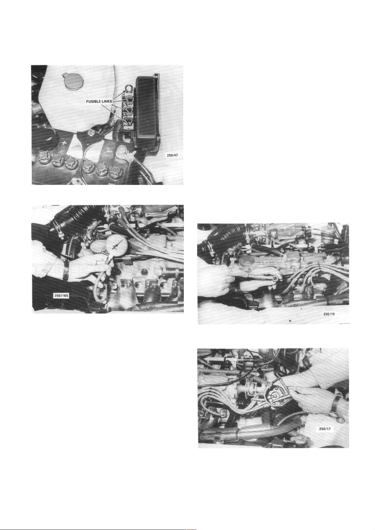
Engine Tune-up
29
View showing the location of the fusible links.
Refer to the Fuel and Engine Management section
for Specifications and Trouble Shooting.
NOTE: When working on or near electronic
ignition systems, care should be taken as
dangerous high voltages are present in both
the primary and secondary circuits.
The ignition switch should be turned off
before removing or installing any electrical
connections otherwise damage to the ignition system as well as severe electrical shock
could result.
TO SERVICE HIGH TENSION LEADS
Check the leads for perishing or cracking and
renew as required. Never attempt to repair defective
carbon impregnated core leads.
The lead may be carefully cleaned, using cloth
moistened with kerosene and then wiped completely
dry.
If an ohmmeter is available the electrical resis-
tance of the leads may be checked as follows:
Check the cylinder compressions using a compression
gauge.
(a) Inject a small amount of engine oil into the
spark plug hole of the cylinder concerned ensuring
that the oil is evenly distributed within the cylinder by
rotating the engine.
(b) Repeat the compression test on the cylinder
concerned.
A substantial increase of compression pressure
indicates faulty or worn piston rings, pistons or
cylinder.
No increase of compression pressure indicates
burnt, obstructed or sticking valves, or a leaking or
blown cylinder head gasket.
(9) Install the fusible link and connect the high
tension lead to the coil.
TO SERVICE THE DISTRIBUTOR
The electronic ignition system requires virtually
no maintenance except for checking of the distributor
cap. rotor and high tension leads as described below.
Check the spark plug high tension leads for cracks and
burnt or corroded terminals.
Check the distributor cap for cracks or tracking
between the terminals
.
Page 28
30
Engine Tune-up
(1) With the distributor cap and leads removed
as an assembly, test one lead at a time, connecting the
meter probes at the spark plug end of the lead and at
the corresponding terminal inside the cap. Resistance
should be less than 15 000 ohms.
(2) If the resistance is more than 15 000 ohms
remove the lead from the distributor cap and check
(he resistance in the lead only. The lead should be
renewed if the resistance is still more than 15 000
ohms.
(3) High distributor cap resistance may be due
to corrosion deposits on the cap terminals. These
deposits should be removed with a small scraper or
emery cloth.
Check the distributor cap for cracks or tracking
between the high tension terminals on both the inside
and outside of the cap. Renew the cap if cracks or
tracking are evident.
Check the carbon brush in the centre of the
distributor cap for evidence of arcing and renew as
necessary.
Check the condition of the rotor and renew if
arced excessively or cracked.
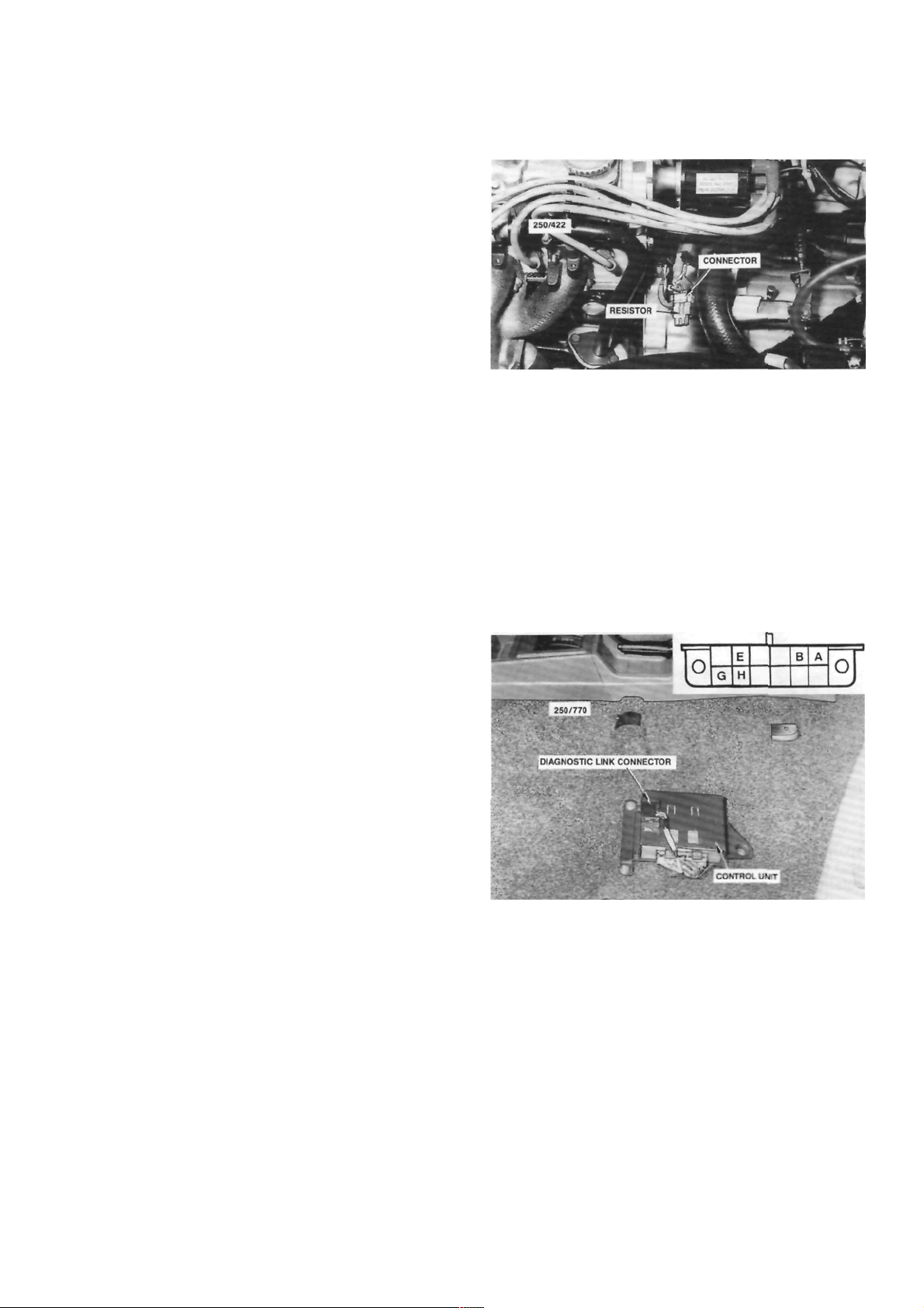
View showing the location of the tachometer pickup
wiring connector with the resistor installed
.
pick up wiring connector which is located on the
ignition coil wiring harness, and connect the positive
lead of an accurate tachometer to the brown wire
terminal in the wiring connector.
(3) Connect the negative lead to a good earthing
point.
HOW TO CONNECT ELECTRICAL TEST
EQUIPMENT
NOTE: Some types of tachometers, timing
lights and ignition system analysers are not
compatible with this type of electronic ignition system and may result in incorrect
readings. It is therefore recommended that
the manufacturer of the test equipment be
consulted before using the equipment.
Do not allow the tachometer lead connector to short to earth as damage to the test
equipment or ignition system may result.
Timing Light
(1) Connect the timing light to the engine fol-
lowing the instrument manufacturers instructions.
NOTE: Do not connect or disconnect the
timing light with the engine running as
voltage surges could damage the alternator.
Do not allow the high tension leads to open
circuit as damage to the ignition system
could result.
(2) Where necessary, connect the power leads of
the timing light to an external power source to prevent
possible transient voltages in the timing light damaging the vehicle alternator.
Tachometer
(1) Ensure that the tachometer is compatible
with the vehicle ignition system.
(2) Disconnect the resistor from the tachometer
TO CHECK AND ADJUST IGNITION TIMING
(1) Connect an accurate tachometer and timing
light to the engine as previously described.
View showing the location of the diagnostic link
connector. Passengers seat removed for clarity.
Inset shows the diagnostic link connector terminal
identification.
(2) Start the engine and allow it to reach normal
operating temperature.
(3) Connect a jumper lead between terminals A
and B on the diagnostic link connector.
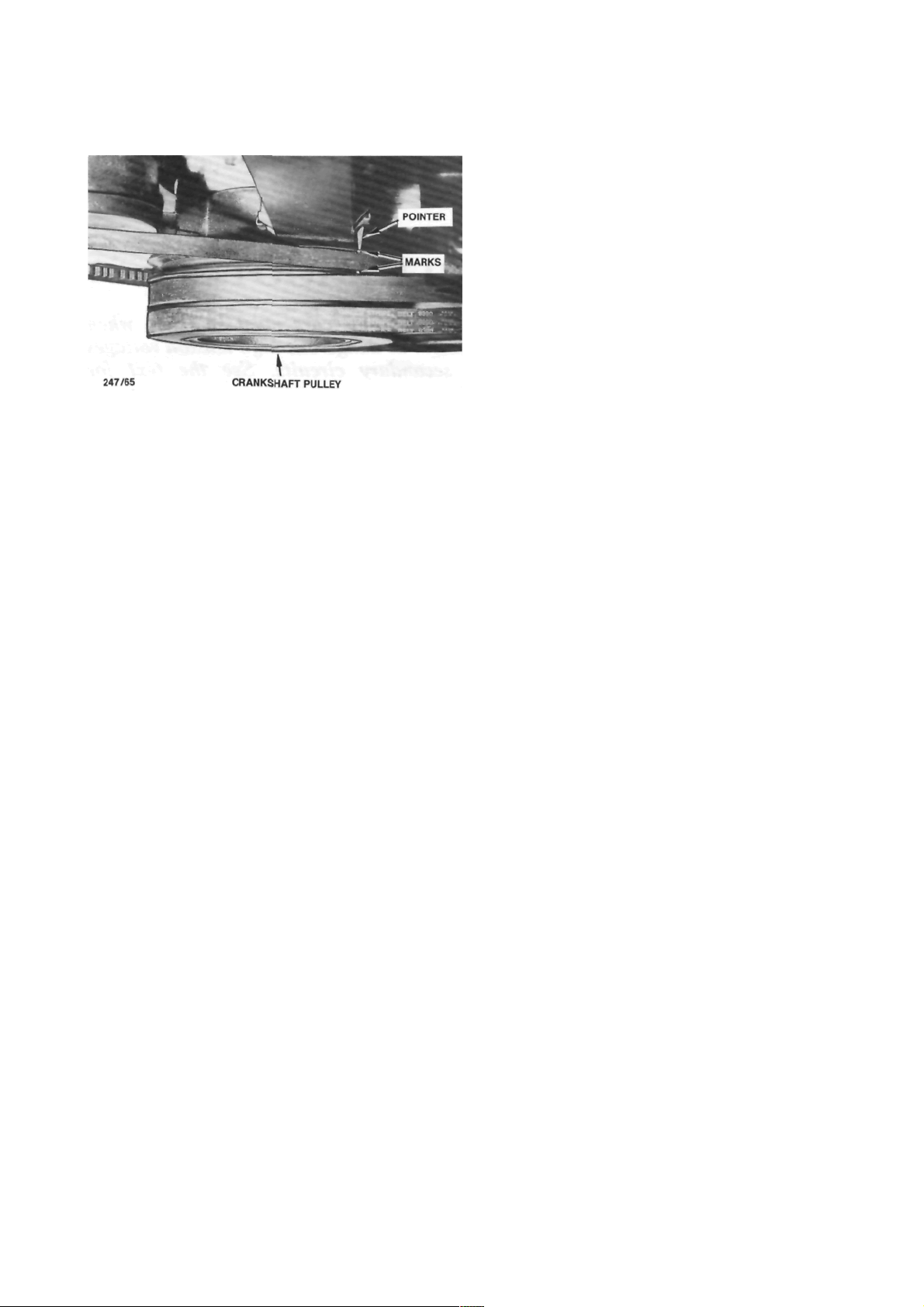
(4) With the engine idling at the specified speed,
check the ignition timing with the timing light.
Correct timing exists when the marks on the
crankshaft pulley are aligned with the pointer on the
inner timing cover.
Page 29
Engine Tune-up
(5) If adjustment is necessary, loosen the distrib-
utor body retaining nuts and turn the distributor body
until the correct setting is obtained.
(6) Tighten the distributor body retaining nuts
and ensure that the timing is still correct.
(7) Remove the jumper lead from the diagnostic
link connector.
(8) Disconnect the timing light from the engine.
View of the engine timing marks showing the 10 deg
BTDC crankshaft notch aligned with the pointer on the
front of the engine.
TO ADJUST IDLE SPEED AND MIXTURE
The idle speed and mixture are not adjusted as
normal service procedure. However, should the performace of the vehicle indicate that the mixture is
incorrect, refer to the Fuel and Engine Management
section for the procedures to test for faulty components in the engine management system.
Page 30
32
ROADSIDE TROUBLE SHOOTING
CAUTION: To prevent severe electrical shock extreme care must be taken when
working on or near the electronic ignition system as dangerous high tension voltages
are produced in both the primary and secondary circuits. See the text for
precautionary notes.
This section deals with the common causes of
engine failure to start, as inevitably there will come a
time when every driver will experience this problem
and will therefore need to call upon his own resources
to rectify the trouble. Roadside breakdowns other
than engine failure can be identified by reference to
the Trouble Shooting section on the particular component affected.
Trouble shooting is only a process of elimination
and provided the procedure is carried out correctly
and systematically an accurate diagnosis of the trouble
can be made in the minimum amount of time.
For an internal combustion engine to run there
are three basic requirements, these are ignition, fuel
and compression. There are other factors of course
but as a rule an engine's failure to start can be
attributed to a fault in one of these three systems.
Reports from field engineers of motoring organisations prove that the biggest percentage of engine
breakdowns are in the order of ignition or electrical
failure first, followed by fuel, with mechanical or
compression failure the least common.
Should the engine fail to start, first check that
there is adequate fuel in the tank and if so. carry out
the following checking procedures in the order described.
1. TROUBLE SHOOTING
jump starting, or being jump started by
another vehicle. If available use jumper
leads equipped with a surge protection device and follow the lead manufacturers instructions carefully, particularly regarding
the connection and disconnection of the
leads.
(1) Ensure that the booster battery is 12 volts
and the negative terminal is earthed.
(2) Ensure that the vehicles are not touching and
that the ignition and all accessories on both vehicles
are switched Off.
(3) Ensure that the transmissions on both vehi-
cles are in Park or Neutral and the handbrakes are
firmly applied.
(4) Remove the vent caps from the battery and
check the electrolyte level. Replenish with distilled
water as necessary.
TO JUMP START A VEHICLE
NOTE: Jump starting a vehicle can be
dangerous if the procedure described below
is not performed correctly. If any doubt
exists, it is recommended that the services of
a competent mechanic be obtained.
The vehicles covered by this manual are
equipped with complex electronic circuitry
which can be damaged by voltage surges.
These voltage surges can be generated when
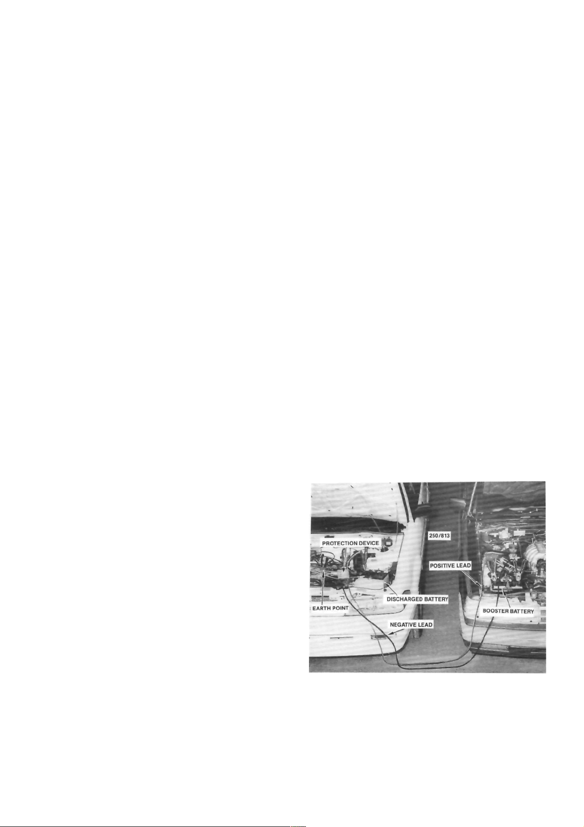
View showing the correct jumper lead connections for
jump starting a vehicle. The leads shown are equipped
with a surge protection device.
Page 31

Roadside Trouble Shooting
(5) Place the vent caps loosely over the cell
apertures.
(6) Connect one en d of t h e red j umper l ead t o
the positive ( + ) battery terminal of the booster
battery and the other end of the red lead to the
positive (+) battery terminal of the discharged battery.
NOTE: The battery emits hydrogen gas
which is explosive. Do not expose the battery
to naked /lames or sparks.
Do not lean over the battery when con-
necting the jumper leads.
Do not allow the ends of the jumper leads
to touch one another or any part of the
engine.
(7) Connect one end of the black juniper lead to
the negative (-) battery terminal of the booster
battery and the other end of the black lead to a good
earthing point on the engine of the vehicle with the
discharged battery.
NOTE: Do not connect the jumper lead
directly to the negative (-) battery terminal
of the discharged battery.
(8) Start the engine on the vehicle with the
booster battery and run the engine at a moderate
speed.
(9) Start the engine on the vehicle with the
discharged battery.
(10) If possible, leave the engines of both vehi-
cles running for 10 minutes.
(11) Disconnect the jumper leads in the reverse
order of the sequence in which they were connected.
2. TO CHECK IGNITION AND ELECTRICAL
SYSTEM
Ensure that the battery posts and terminals are clean.
(d) Where necessary carry out repairs to (b) and
(c).
Repeat the check procedure. Should the starter
motor still not operate, or the lamps not illuminate,
one or more of the following faults may be the cause:
No starter motor operation or lamps: Battery flat
or defective.
Lamps illuminate but no starter operation: Starter
motor drive jammed in mesh with flywheel ring gear.
Starter motor or solenoid defective. Ignition/starter
switch faulty. On automatic transaxle models, faulty
neutral safety switch.
Lamps dim and starter operation sluggish: Dis-
charged battery or fault in starter motor. Battery flat
due to broken fan belt or defective alternator. Faulty
battery due to cell breakdown.
NOTE: Electronic ignition systems can produce dangerously high voltages in both the
primary and secondary circuits. For this
reason, extreme care must be taken when
performing these checks. When disconnect-
(1) Switch on the ignition and check for warning
lamp illumination on the dashboard.
(2) Operate the starter and check that the starter
rotates the engine at a steady speed.
(3) Switch on the headlamps and check for good
light intensity.
Should the lamps not illuminate or the starter
motor not turn the engine, carry out the following
steps:
(a) Remove the battery terminals and clean both
terminals and posts. Connect the terminals and where
applicable tighten firmly but not excessively.
(b) Check that the earth lead from the battery to
the engine or body frame is not broken and that the
connections are clean and secure.
. (c) Check that the lead from the battery to the
starter motor or starter solenoid is intact and has a
clean and secure connection.
Securely earth the body of a test spark plug to check
for sparks at the spark plug leads.
Page 32

Roadside Trouble Shooting
ing the wiring from any component, ensure
that the ignition switch is off and the
negative battery terminal is disconnected to
prevent damage to the solid state circuitry.
(4) Open the electrode gap of a serviceable spark
plug to 6 mm. Securely earth the plug using a jumper
lead or by tying the plug to an earthed engine
component.
(5) Disconnect the high tension lead from a
spark plug and connect it to the test spark plug.
(6) Have an assistant operate the starter motor.
(7) Check that a spark, if any, jumps the gap on
the test spark plug.
If the spark is satisfactory, proceed to operation
(8).
If there is no spark, proceed as follows:
(a) Check the high tension leads to ensure that
they are dry and that the insulation is not cracked or
perished. Check the ends of the leads for burning.
Using an ohmmeter, measure the resistance in
each high tension lead. The resistance should be no
more than 15 000 ohms per lead.
Check the spark plug high tension leads for cracks and
burnt or corroded terminals.
(b) Check the distributor cap to ensure that it is
dry and clean. Examine both the inside and outside of
the cap for cracks or tracking, particularly between the
high tension lead segments.
Check that the carbon brush in the centre of the
distributor cap interior face is clean and dry and
ensure that the brush moves freely in and out of its
locating hole.
(c) Check the rotor arm for cracks, deposits and
burning on the metal arm.
(d) Ensure that the high tension leads have dry.
clean and secure connections on the distributor cap.
(8) If the above checks result in a good spark at
the spark plug high tension leads but the engine is still
not operating satisfactorily, remove all the spark plugs
and check the condition and electrode gap as described in the Engine Tune-up section under the
appropriate heading.
3. TO CHECK FUEL SYSTEM
Due to the complex nature of the EFI system, it is
recommended that should the following checks prove
satisfactory but the engine fail to start, reference be
made to the Fuel and Engine Management section of
this manual or a Nissan workshop be consulted.
(1) Check that the fuel tank contains a reasonable amount of fuel.
(2) Have an assistant switch the ignition on and
off while squeezing the fuel supply hose with the
fingers. If the fuel pump is operating it should be
possible to feel the fuel pressure increase for approximately two seconds.
NOTE: When conducting the above test it
should be possible to hear the fuel pump and
ignition relays clicking when the ignition is
switched on and off
If the fuel pump relay fails, power will be
supplied to the fuel pump via the oil pressure
Check the distributor cap for cracks or tracking
between the terminals.
Squeeze the fuel supply hose while the ignition is
switched On. An increase in pressure should be felt
.
Page 33

Roadside Trouble Shooting
View showing the location of the fuel pump fuse and
the EGI and fuel pump relays.
switch. When starting the engine, the fuel
pump will not operate until the oil pressure
is sufficient to extinguish the oil pressure
warning lamp. Therefore it will be necessary
to operate the starter motor for a longer
period than usual to start the engine.
(3) I f th e fu e l p u mp c ann o t be fe l t o p erat i ng,
check the fuel pump fuse located in the fuse panel
adjacent to the steering column.
If the fuel pump fuse is serviceable, refer to the
Fuel and Engine Management section for detailed
tests on the fuel pump.
(4) Check that all fuel hose connections are
secure.
(5) Remove the spark plugs and check for petrol
saturation of the electrodes which indicates flooding.
Thoroughly clean and dry the spark plugs before
replacement.
Fully depress the throttle pedal and turn the
ignition switch to the start position. If the engine does
not start, proceed as follows.
Ensure that all fuel connections are securely tightened.
35
Check that the MAP sensor hose is not blocked or split
and ensure that all electrical connections are clean and
secure.
If flooding persists, refer to the Fuel and Engine
Management section.
(6) Check that all EFI electrical wiring connec-
tors are clean and secure.
(7) Check that the MAP sensor vacuum hose is
securely connected at each end and is not split or
blocked.
4. TO CHECK MECHANICAL SYSTEM
The following check procedure assumes that the
starter motor will rotate the engine. If not, on manual
transaxle models, depress the clutch pedal to disengage the engine from the transaxle in case the fault lies
within the transaxle.
If the starter motor will not rotate the engine, it
will be necessary to remove the starter motor and
attempt to turn the engine over manually. This will
establish whether the fault lies with the starter motor,
which could be jammed or defective, or with the
engine, which could be seized or have broken internal
components such as connecting rods, pistons and
crankshafts etc.
If the starter motor is not at fault and the engine
will not rotate manually, refer to the Engine Mechanical Trouble Shooting heading in the Engine section.
It should be noted that the only way that cylinder
compression can be accurately tested is with a compression gauge. The method described in the following
procedure is only intended to give a rough indication
when checking for causes of engine breakdown,
(I) When the engine is cool, check for loss of
coolant from the cooling system.
If coolant loss is evident, check carefully for any
indication of external leakage. Remove the engine oil
dipstick and check for water contamination (emulsification) of the oil. When oil mixes with water it will
Page 34

36
Check the engine oil for level and dilution on the
dipstick.
Roadside Trouble Shooting
View showing the location of the fusible links.
turn creamy. The oil level will also have increased. If
the oil is emulsified, proceed to operation (5).
(2) Remove the fusible link that is positioned
third from the front of the fusible link connection
block, located at the rear of the battery. Disconnect
the coil high tension lead from the coil.
(3) Remove all of the spark plugs except one.
(4) Have an assistant operate the ignition switch
to rotate the engine and listen to the sound made by
the engine as it is being turned over. Move the spark
plug to a different cylinder and repeat the lest.
By performing the same test on all cylinders, a
rough comparison can be made to determine if there
is any loss of compression in any cylinder. This will be
apparent by the different sound made by the engine as
it is being turned over.
Normally, if the compression is satisfactory the
cylinder with the spark plug installed will create a
resistance to the rotating engine.
However, if the compression is low in a particular
cylinder, the engine will turn over easily and smoothly
when that spark plug is in place.
(5) If t h e above check s s h ow a loss o f coolant
which is present in the engine oil or on the spark plug,
one or more of the following faults may be the cause:
Blown cylinder head gasket.
Cracked cylinder or cylinder head.
If the compression check showed any weak or
inconsistent compressions, in addition to the above
faults any of the following could also be the cause:
Broken piston{s)
Burnt or broken valve(s).
Provided the previous checks do not indicate an
internal leakage of coolant, proceed with the following:
(6) Remove the distributor cap and, with the aid
of an assistant operating the starter motor, check that
the rotor arm rotates as the engine turns over.
(7) Remove the camshaft housing top cover and.
again with an assistant operating the ignition switch,
check that all the valves open and close as the engine
turns over.
If the rotor arm or valves do not operate with
engine rotation, one of the following faults may be the
cause:
Rotor arm does not turn but valves operate:
Distributor drive shaft broken.
Rotor arm and valves do not operate: Broken
camshaft drive belt. Sheared crankshaft timing gear
drive key. Sheared camshaft liming gear drive dowel.
Provided that all the previous checks have been
performed correctly and the operator is satisfied that
none of the components are at fault, all that remains
is for the ignition and valve timing to be checked. It
should be noted, however, that if loss of valve timing
proves to be the fault, the cause of this occurrence
must be sought and rectified.
(8) In ord er to check the valve timing it will be
necessary to remove the distributor cap and the
camshaft housing top cover and turn the engine
clockwise via the crankshaft pulley until No. 1 piston
is at TDC on the compression stroke. In this position
the valves of No. 1 cylinder should be closed, the
valves of No. 4 should be rocking and the distributor
rotor should be pointing to the No. 1 high tension lead
segment in the distributor cap.
Page 35

37
ENGINE
SPECIFICATIONS
ENGINE ASSEMBLY
Type........................................................... 4cyl OHC
Models ............................................. 1.6 liter, 1.8 liter
Capacity:
1.6 liter...................................................1 598 cc
1.8 liter ................................................... 1 796 cc
Firing order...................................................... 1 -3-4-2
Bore:
1.6 liter .................................................. 80.0 mm
1.8 liter .................................................. 84.8 mm
Stroke ........................................................... 79.5 mm
Maximum compression pressure
variation between cylinders ......................... 100 kPa
NOTE: Specifications regarding engine tuning arc listed in the Engine Tune-up section.
CYLINDER BLOCK
Type......................................................... 4 cyl in line
Material ........................................................Cast iron
Bore diameter:
1.6 liter ...............79.995-80.065 in three groups
1.8 liter .................84.755-84.905 in four groups
Bore taper limit ......................................... 0.013 mm
Bore ovality limit ..................................... 0.013 mm
Block face distortion limit ..........................0.10 mm
Maximum height of piston above block
face at top dead centre:
1.6 liter ..................................................0.00 mm
1.8 liter .................................................. 0.50 mm
Bore oversize................................................ 0.50 mm
CYLINDER HEAD
Type........................................... One piece, cross flow
Material ............................................ Aluminum alloy
Distortion limit.......................................... 0.025 mm
Machining limit ...........................................0.25 mm
Minimum overall height after machining:
1.6 liter.................................................95.50 mm
1.8 liter.................................................94.80 mm
Valve seat angle..........................................45 degrees
Valve seat contact width:
Inlet................................................... 1.0-1.5 mm
Exhaust ............................................. 1.7-2.2 mm
Valve stem protrusion ................. 18.4 mm from top
of cylinder head
Valve guide height .......... 12.2-12.5 mm from top of
cylinder head
VALVES AND SPRINGS
Valve length ..............................................104.2 mm
Valve head diameter:
1.6 liter —
Inlet........................................................ 36.0 mm
Exhaust .................................................. 32.0 mm
1.8 liter -
Inlet....................................................... 41.8 mm
Exhaust ................................................. 36.5 mm
Valve stem diameter:
Inlet...........................................6.998-7.012 mm
Exhaust .....................................6.978-6.992 mm
Valve stem to guide clearance:
Inlet...........................................0.018-0.052 mm
Exhaust .....................................0.038-0.072 mm
Oversize valve system availability......... 0.075, 0.150
Valve face angle ......................................... 44 degrees
Valve spring tension:
Valve closed .......................... 300 N at 37.5 mm
Valve open............................. 765 N at 26.5 mm
TAPPETS
Type ............................................................. Hydraulic
Operating length ........................................63.26 mm
Diameter ....................................... 21.392-21.405mm
Leak down rate............. 2-10 seconds for 3.175 mm
PISTONS AND GUDGEON PINS
Piston type .......................................Aluminum alloy
Diameter:
1.6 liter........79.955-80.035 mm in 8 categories
1.8 liter.......84.725-84.885 mm in 16 categories
and 0.250 mm
in increments of 0.01 mm
in increments of 0.01 mm
Page 36

38
Engine
*Piston skirt to cylinder bore clearance:
1.6 liter.....................................0.020-0.040 mm
1.8 liter .....................................0.010-0.030 mm
Gudgeon pin length:
1.6 liter ......................................................53 mm
1.8 liter .................................................. 61.5 mm
Gudgeon pin diameter.................20.990-20.995 mm
Gudgeon pin clearance in piston:
1.6 liter.....................................0.010-0.020 mm
1.8 liter..................................0.0055-0.0115 mm
Gudgeon pin offset in piston:
1.6 liter .........0.35-0.65 mm towards thrust side
1.8 liter ................... 0.8 mm towards thrust side
*Measured 9 mm from the bottom of the piston skirt
for 1.6 liter models and 6 mm from the bottom of the
piston skirt for 1.8 liter models.
PISTON RINGS
Rings per piston:
Compression .......................................................2
Oil control.......................................................... 1
End gap:
Compression ................................ 0.30-0.50 mm
Oil control —
1.6 liter ......................................... 0.33-1.10 mm
1.8 liter ......................................... 0.40-1.40 mm
CONNECTING RODS AND BEARINGS
Connecting rod side clearance............ 0.07-0.24 mm
Maximum connecting rod weight variation..8 grams
Crankpin bearing oil clearance.......0.019-0.063 mm
Undersize —
No. 1 .....................................42.355-42.370 mm
No. 2......................................42.605-42.620 mm
No. 3 .....................................42.855-42.880 mm
No. 4......................................43.105-43.120 mm
No. 5 .....................................43.355-43.370 mm
*An undersize camshaft can be identified by a violet
flash between the inlet and exhaust lobes of No. 2
cylinder.
Housing diameter;
Standard —
No. 1 .....................................42.500-42.525 mm
No. 2 .....................................42.750-42.775 mm
No. 3 .....................................43.000-43.025 mm
No. 4......................................43.250-43.275 mm
No. 5 .....................................43.500-43.525 mm
*Undersize —
No. 1 .....................................42.400-42.425 mm
No. 2 .....................................42.650-42.675 mm
No. 3 .....................................42.900-42.925 mm
No. 4......................................43.150-43.175 mm
No. 5 .....................................43.400-43.425 mm
*An undersize camshaft housing can be identified by
a violet flash on the centre camshaft bearing support.
LUBRICATION
Oil pump type .......................................Involute gear
Filter type................................... Full flow disposable
Oil pressure at 4 000 rpm.....................480-620 kPa
Rotor assembly end float.................. 0.03-0.010 mm
Rotor teeth backlash......................... 0.010-0.20 mm
CRANKSHAFT AND MAIN BEARINGS
Number of bearings.................................................. 5
End float taken at...................... No. 3 main bearing
End float..........................................0.070-0.302 mm
Bend limit ...................................................0.03 mm
Main bearing oil clearance .............0.015-0.040 mm
Main bearing journal diameter.. .57.982-57.995 mm
Crankpin diameter.......................48.971-48.987 mm
FLYWHEEL
Ring gear run out limit.................................. 0.3 mm
Clutch face regrind limit .............................. 0.3 mm
CAMSHAFT
Drive ......................................................Toothed belt
End float .............................................. 0.04-0.14 mm
Bend limit ................................................... 0.03 mm
Bearings...........................................Direct in housing
Journal diameter:
Standard —
No. 1 ..................................... 42.455-42.470 mm
No. 2 .....................................42.705-42.720 mm
No. 3 .....................................42.955-42.970 mm
No. 4 .....................................43.205-43.220 mm
No. 5 .....................................43.455-43.470 mm
TORQUE WRENCH SETTINGS
*Cylinder head bolts:
Initial torque............................................. 25 Nm
1st stage ......................................... + 60 degrees
2nd stage........................................ + 60 degrees
3rd stage......................................... + 60 degrees
4th stage, engine at operating
temperature .............................. + 30-50 degrees
Exhaust manifold nuts.................................... 22 Nm
Exhaust manifold flange nuts ......................... 22 Nm
Inlet manifold nuts.......................................... 22 Nm
Throttle body to inlet manifold nuts ..............12 Nm
Camshaft liming gear bolt...............................45 Nm
Camshaft retaining plate bolts ......................... 7 Nm
Camshaft cover bolts.........................................8 Nm
Thermostat cover bolts....................................15 Nm
*Main bearing bolts..................60 Nm + 45 degrees
Connecting rod bearing
cap nuts................................... 35 Nm + 45 degrees
* Crankshaft timing
gear bolt..................................145 Nm + 35 degrees
*Flywheel bolts
(microencapsulated) ................ 60 Nm + 30 degrees
*Drive plate bolts (microencapsulated)...........60 Nm
Water pump bolts............................................ 25 Nm
Page 37

A
Oil pump cover plate screws............................ 6 Nm
Oil pump mounting bolts.................................. 6 Nm
Oil pump pickup bolts
(coat with Loctite 242) ..................................... 8 Nm
Sump bolts (coat with Loctite 242).................. 5 Nm
Sump drain plug ..............................................35 Nm
*Use new bolts
Head bolts maximum torque 135 Nm
1. ENGINE MECHANICAL TROUBLE
SHOOTING
ENGINE MISSES AT IDLING SPEED
NOTE: For other causes of engine misfire,
refer to the Fuel and Engine Management
section.
(1) Blown head gasket: Check the cylinder com-
pressions and renew the head gasket as necessary.
(2) Burnt valves or seats in the cylinder head:
Check the cylinder compressions and overhaul the
cylinder head as necessary.
(3) Broken or worn piston rings: Check the
cylinder compressions and renew the piston rings as
necessary.
(4) Weak or broken valve springs: Remove the
camshaft housing top cover and check the condition
of the valve springs.
(5) Air leak at the inlet manifold gasket; Check
for air leaks by applying oil around the manifold
joints. Renew the gasket if an air leak is evident.
NOTE: Use a compression gauge and check
the compression pressure in each cylinder as
described in the Engine Tune-up section. If
a low pressure reading is indicated in one or
more cylinders, remove the cylinder head for
gasket and valve inspection. Should the
Engine
gasket and valves prove satisfactory, inspect
the cylinder bores, pistons and rings.
Check for air leaks at the inlet manifold
by applying engine oil around the manifold
joints. If the oil can be seen or heard sucking
into the manifold or excessive smoke begins
to issue from the exhaust system, there is an
air leak at the inlet manifold.
NOISY VALVE OPERATION
(1) Faulty hydraulic tappets: Renew the faulty
tappet assemblies.
(2) Weak or broken valve springs: Remove the
camshaft housing top cover and check the condition
of the valve springs.
(3) Worn valve guides: Overhaul the cylinder
head as described in this section.
(4) Worn rocker gear: Remove (he rocker gear
and check the components for wear.
Camshaft lobe wear is also a cause of noisy valve
operation.
39
ir leaks at the inlet manifold can be located by
applying engine oil around the suspect joints.
BIG END BEARING NOISE
(1) Inadequate oil supply: Check the oil level in
the sump and the condition of the oil pump and relief
valve. Renew the oil filter.
(2) Excessive bearing clearance: Renew the bearing shells, check and regrind the big end journals if
oval or tapered.
(3) Thin oil or oil diluted by petrol or water:
Change to the correct oil grade. Check and rectify the
cause of the oil dilution. Check that the engine is not
operating in overheat conditions.
(4) Low oil pressure: Check the engine oil level.
Check the pressure relief valve and spring and the oil
filter bypass valve.
(5) Misaligned big end bearings: Align the con-
necting rods and renew the big end bearing shells.
NOTE: Big end bearing noise is indicated
by a metallic knock which is usually loudest
at approximately 60 km/h with the throttle
Page 38

40
Check the engine oil for level and dilution on the
dipstick.
dosed. Before dismantling the engine to
inspect the big ends check the engine oil for
correct level and dilution on the dipstick.
Also, remove the oil pressure sender unit
and connect an oil pressure gauge into the
oil gallery to check the oil pressure readings.
MAIN BEARING NOISE (APPARENT)
(1) Loose flywheel: Tighten the flywheel securing
bolls to the specified torque.
(2) Low oil pressure: Check the bearing to
journal clearance. Check the condition of the oil
pump and pressure relief valve. Recondition the oil
pump as necessary.
(3) Excessive crankshaft end float: Renew the
main bearings.
(4) Crankshaft journals out of round and exces-
sive bearing to journal clearance: Regrind the journals
and renew the bearings (undersize).
(5) Insufficient oil supply: Replenish the oil in
the sump to the correct level.
NOTE: Main bearing noise is indicated by a
heavy but dull knock when the engine is
under load. A loose flywheel is indicated by
a thud or dull click when the ignition is
turned off. It is usually accompanied by
vibration.
Crankshaft end float noise is indicated by
a sharp rap at idle speed. The crankshaft
can be readily checked for excessive end
float by levering the crankshaft backwards
and forwards.
If the oil pressure is not satisfactory,
remove the main bearing caps and assess
the bearing clearance using the Plastigage
method as described in this section. Ovality
and wear on the main bearing journals can
only be checked with a micrometer after the
crankshaft has been removed.
Engine
EXCESSIVE OIL CONSUMPTION
(1) Oil leaks: Check and renew the engine gas-
kets or seals as necessary.
(2) Damaged or worn valve stem oil seals:
Dismantle the cylinder head and renew the damaged
or worn oil seals.
(3) Excessive valve stem to valve guide clear-
ance: Ream the valve guides and renew the valves as
necessary.
(4) Worn or broken piston rings: Renew the
piston rings on all pistons.
(5) Rings too tight or stuck in the grooves:
Renew the rings and clean the ring grooves.
(6) Excessive wear in the cylinders, pistons and
rings: Recondition the cylinders and renew the pistons
and rings.
(7) Compression rings incorrectly installed. Oil
rings clogged or broken: Renew the piston rings.
NOTE: Before checking the engine for oil
leaks the engine should be completely degreased and cleaned. Run the engine at
operating temperature for a period and
visually check for oil leakage. By placing
white paper on the floor directly beneath the
engine any excessive leak can be readily
pinpointed.
Damaged or worn valve stem oil seals
which allow oil to be drawn down past the
valve stems into the combustion chambers
can be diagnosed by allowing the engine to
idle for a few minutes and then opening the
throttle. If oil is being drawn past the valve
stems a heavy discharge of blue smoke will
be seen at the tailpipe.
Piston, ring and cylinder bore troubles are
normally accompanied by a loss of compression. Cylinder compression can only be
accurately assessed by using a compression
gauge.
Run the engine over white paper to check for oil leaks.
Page 39

Engine
41
DROP IN OIL PRESSURE
(1) Oil level low in the sump: Check and replen-
ish the oil to the full mark on the dipstick.
(2) Thin or diluted oil: Change to the correct oil
grade and rectify the source of dilution.
(3) Oil pump relief valve stuck or spring broken;
Free up the relief valve or renew the broken relief
valve spring.
(4) Excessive bearing clearance: Renew the bear-
ing shells or recondition the crankshaft journals as
necessary.
(5) Excessive wear of the oil pump components:
Renew or recondition the oil pump.
NOTE: If the vehicle is not equipped with an
oil pressure gauge remove the oil sender unit
and connect a pressure gauge into the oil
gallery. Check the oil pressure with the
engine cold and hot. If the oil pump or relief
valve are faulty. low pressure will be indicated with the engine both hot and cold.
However, if the bearings are at fault a fairly
high oil pressure will be indicated when the
engine is cold, but a marked drop in pressure
will occur when the engine is hot.
ENGINE WILL NOT ROTATE
(1) Starter motor drive jammed: Remove the
starter motor. Check and renew the damaged drive
and/or flywheel ring gear.
(2) Engine overheated and seized: Remove and
dismantle the engine. Check and renew any damaged
components. See the following note.
(3) Water in the cylinder due to a blown head
gasket or cracked cylinder block or head: Remove the
cylinder head. If the gasket is blown, check for
cylinder block and head distortion and reface if
necessary. Renew the cylinder head and/or cylinder
block if cracked.
(4) Broken crankshaft, connecting rod. piston
etc. due to overheating, fatigue etc: Remove and
dismantle the engine. Examine and renew any components as necessary.
(5) Valve head broken off due to overheating,
fatigue etc: Remove the cylinder head and check the
head, piston and cylinder bore for damage. Repair or
renew as necessary.
NOTE: Invariably when an engine seizes
because of overheating due to lack of oil
and/or water, damage is done to the bearings, pistons etc. Although there may be
instances where an engine will start and run
after it has cooled down and the oil and
water have been replenished, it will usually
be found that oil consumption increases, oil
pressure decreases and the engine will be
noisier, depending on the degree of damage.
When a cylinder head gasket blows allow-
ing water into the cylinders, or compression
loss between the cylinders, it is essential to
check the gasket faces on the cylinder block
and head for distortion. Sufficient water can
enter a cylinder because of a blown head
gasket, cracked cylinder or head to prevent
an engine from rotating.
This is normally preceded by difficult
starting, misfiring, excessive steam from the
exhaust and loss of water from the radiator.
Frequent jamming of the starter motor
drive with the flywheel ring gear can be due
to a bent starter armature shaft or damaged
teeth on the drive and/or ring gear. With the
starter motor removed, the flywheel ring
gear teeth can be examined through the
starter motor mounting aperture. Renewal
of the ring gear requires removal of the
transaxle, clutch and flywheel on manual
transaxle models and the removal of the
transaxle and drive plate on automatic
transaxle models. To check for a bent armature shaft, rotate the shaft by hand while
holding the end in close proximity to a fixed
object.
2. DESCRIPTION
The 1.6 and 1.8 liter engines are basically identi-
cal in design.
Both engines share the same stroke. The 1.8 liter
engine has a larger bore thus giving it increased
capacity.
The engine is a four cylinder, inline, overhead
camshaft design transversely mounted in the front of
the vehicle.
The camshaft runs in five integral support bearings in the camshaft housing which in turn is mounted
directly on to the cylinder head and retained by the
cylinder head bolts.
Camshaft end float is controlled by a retaining
plate engaged in a groove machined in the rear
camshaft journal. The camshaft is driven by the
crankshaft timing gear via a reinforced rubber belt.
The aluminum cross flow cylinder head houses
the tappets, rocker arms and valve assemblies. An oil
pressure relief valve is installed to the cylinder head to
maintain oil pressure to the hydraulic tappets at a
predetermined setting.
The exhaust valve springs are equipped with
rotators mounted below the valve springs which rotate
the exhaust valve assemblies. The rocker arms pivot
on hydraulic tappet assemblies and locate in notched
lash pads mounted on the valve stems. The camshaft
lobes bear directly onto the rocker arms and due to
the characteristics of the hydraulic tappet assemblies,
no provision is made for tappet clearance adjustment.
Page 40

42
Engine
The cylinder block is a cast iron alloy, deep skirt
design and the crankshaft is supported in the cylinder
block by five precision insert replaceable main bearings. Crankshaft end float is controlled by the flanged
centre main bearing. Connecting rods are I section
forgings equipped with precision insert replaceable big
end bearings. The gudgeon pins are an interference fit
in the connecting rod and a floating fit in the piston.
The cast aluminum pistons are equipped with
two compression rings and one oil control ring.
The twin rotor, involute gear oil pump is mounted
directly to the front face of the cylinder block. The
inner rotor is internally driven by the crankshaft. The
oil pump pressure relief valve is not adjustable, and
consists of a plunger and spring mounted in the oil
pump body.
The pump draws oil through a screen in the sump
and delivers it, via a full flow replaceable oil filter, to
the oil gallery from where it is distributed to the
hydraulic tappets, camshaft and crankshaft bearings
and to the overhead rocker and valve mechanism.
3. ENGINE AND TRANSAXLE ASSEMBLY
Special Equipment Required:
To Remove and Instill — Suitable lifting tackle,
extra long chassis stands, suitable trolley
TO REMOVE
NOTE: Due to the high residual pressure
within the fuel system, it will be necessary to
depressurize the system before removing any
fuel supply components. Refer to the Fuel
and Engine Management section for the
correct procedure.
(1) Disconnect the negative battery terminal.
(2) Mark around the bonnet hinges with a soft
lead pencil Co facilitate correct installation. With the
aid of an assistant, remove the bonnet retaining bolts
and remove the bonnet from the vehicle.
(3) Drain the engine and transaxle lubricant.
(4) Open the coolant drain tap located on the
lower radiator pipe and drain the coolant.
(5) Loosen the hose clips and disconnect the
heater hoses from the heater pipes at the bulkhead.
NOTE: Do not use excessive force to remove
the heater hoses from the heater pipes or the
heater core will become dislodged from the
heater unit. If necessary, cut the heater
hoses from the pipes using a sharp knife.
(6) Loosen the hose clamps and disconnect the
radiator hoses from the engine assembly.
(7) Disconnect the positive lead from the bat-
tery.
(8) On 1.8 liter models, disconnect the air inlet
duct.
(9) On 1.6 liter models, remove the air cleaner
assembly. Refer to the Fuel and Engine Management
section if necessary.
(10) Disconnect the throttle cable from the throt-
tle body and from the camshaft housing top cover
bracket, if applicable.
(11) Disconnect the fuel supply and return hoses.
Mark the hoses as an aid to installation.
(12) Suitably mark and disconnect the charcoal
canister hoses.
(13) Disconnect the injector wires from the injec-
tors. On 1.6 liter models, slide the wiring out from the
throttle body.
(14) Disconnect the wiring from the throttle po-
sition sensor (TPS), idle air control (IAC) valve,
oxygen (O
) sensor wire, coolant temperature sensor,
2
coolant sender and on 1.8 liter models, the manifold
air temperature (MAT) sensor.
(15) Disconnect the wiring connector adjacent to
the top heater hose, the wiring from the alternator and
the two earth wires from underneath the cylinder head
bolts.
(16) Lay the wiring loom over on the passenger
side of the engine compartment, clear of the work
area.
(17) On manual transaxle models, loosen the
clutch cable adjusting nuts and remove the cable
through the slot in the lever. Remove the clutch cable
bracket from the transaxle after removing the retaining bolts and place the cable to one side.
(18) Disconnect the wiring from the starter mo-
tor, speedometer sender and on manual transaxle
models, the reverse lamp switch wiring.
(19) If applicable, disconnect the power steering
lines from the pump and drain the fluid into a
container. Suitably plug the lines and the pump to
prevent the entry of dirt.
(20) On automatic transaxle models, disconnect
the selector cable and bracket from the transaxle
assembly.
Disconnect the transaxle oil cooler lines from the
transaxle. Plug the lines and fittings to prevent the
entry of dirt etc.
(21) Loosen the front wheel nuts, raise the front
of the vehicle and support it on extra long chassis
stands. Ensure that the vehicle is high enough to allow
removal of the engine from underneath.
(22) Remove the front wheels and the engine
splash guards from the vehicle.
(23) On manual transaxle models, remove the
stay rod and control rod bolts and nuts and disconnect
the rods from the transaxle.
(24) Remove the lower control arm to steering
knuckle ball joint nuts and separate the ball joints
from the steering knuckle by holding a dolly or a
hammer against one side of the steering knuckle and
hitting the other side with a hammer. The taper on the
ball joint will release from the steering knuckle.
(25) Pull the steering knuckles outward swiftly to
Page 41

Engine
43
CAMSHAFT HOUSING TOP COVER
Front view of the 1.8 liter engine and automatic transaxle assembly removed from the vehicle.
release the driveshafts from the transaxle. Tie the
driveshafts to the underbody of the vehicle using wire
and ensuring that excessive strain is not placed on the
joints.
NOTE: If the driveshafts will not release
from the transaxle, a lever can be used
between the driveshaft and the transaxle.
Care must be taken when using the lever not
to damage the transaxle oil seals.
(26) Remove the engine pipe from the engine.
Refer to the procedure at the end of this section if
necessary.
(27) Remove the engine crossmember retaining
bolts and nuts and remove the crossmember from
beneath the vehicle.
(28) Attach the lifting tackle to the engine and
raise the engine slightly to take the weight off the
engine mountings.
(29) Remove the front, rear, left and right engine
mounting bolts and nuts. Withdraw the mountings
from the engine compartment.
(30) Slowly lower the engine and transaxle assem-
bly from the engine compartment.
On air conditioned vehicles, remove the air
conditioning compressor and hoses after the engine
has been lowered slightly. Secure the compressor to
one side, clear of the work area, with wire or similar.
NOTE: Do not disconnect the hoses from
the air conditioning compressor. Escaping
refrigerant can cause frostbite and eye damage.
(31) Lower the engine and transaxle assembly
onto a suitable trolley and maneuver the engine from
beneath the vehicle.
TO INSTAL
Installation is a reversal of the removal procedure
with attention to the following points:
(1) Position the engine and transaxle assembly
beneath the front of the vehicle.
(2) Install the lifting tackle and raise the engine
assembly into position in the engine compartment.
NOTE: On air conditioned models, ensure
that the air conditioning compressor is installed to the engine as the engine is installed to the engine compartment.
(3) Install th e engine and transaxle
assembly
mounting nuts, bolts and washers finger tight before
the full weight of the assembly is taken by the
Page 42

44
Engine
Rear three quarter view of the 1.8 liter engine and automatic transaxle assembly.
mountings. Lower the assembly onto the mountings
and tighten the mounting nuts and bolts.
(4) Install a new exhaust flange gasket.
(5) Fill the engine and transaxle with the correct
quantity and grade of lubricant.
(6) Fill the cooling system as described in the
Cooling and Heating Systems section.
(7) On models with power steering, fill the power
steering reservoir with the recommended fluid.
(8) Start and run the engine until it reaches the
normal operating temperature and check for fuel, oil
and coolant leaks.
4. MANIFOLDS
INLET MANIFOLD - 1.6 Liter Models
To Remove and Install
NOTE: Due to the high residual pressure
within the fuel system, it will be necessary to
depressurise the system before removing the
fuel supply components. Refer to the Fuel
and Engine Management section for the
correct procedure.
(1) Disconnect the negative battery terminal.
(2) Remove the wingnuts retaining the air
cleaner to the throttle body, lift the air cleaner
upwards slightly and disconnect the vacuum hoses.
(3) Drain the cooling system as described in the
Cooling and Heating Systems section.
(4) Loosen the hose clamps and disconnect the
engine coolant hoses from the rear of the manifold.
(5) Disconnect the small branch of the engine
ventilation hose from the rear of the inlet manifold.
(6) On automatic transaxle models, disconnect
the kickdown cable from the throttle lever by releasing
the wire spring clip and removing the cable end socket
from the ball.
(7) Turn the throttle lever to the full throttle
position. Using the slack in the throttle cable, release
the throttle cable end through the slot provided.
Page 43

Engine
45
Installed view of the inlet manifold. 1.6 liter models. Air
cleaner removed.
(8) Remove the bolts retaining the throttle cable
bracket to the inlet manifold and place the bracket
with cable(s) attached to one side.
(9) Suitably mark the supply and return fuel
hoses and disconnect them from the throttle body.
(10) Suitably mark and disconnect the air pre-
heat, map sensor, charcoal canister and brake booster
vacuum hoses from the throttle body.
(11) Disconnect the electrical connector from the
throttle body.
(12) Remove the inlet manifold nuts and with-
draw the inlet manifold assembly. Discard the gasket.
Installation is a reversal of the removal procedure
with attention to the following points:
(1) Ensure that all the carbon and old gasket
material is cleaned from the manifold and cylinder
head faces.
(2) Check the face of the manifold for distortion
using a straight edge and a feeler gauge.
(3) Use a new gasket and ensure that the mani-
fold retaining nuts are tightened to the specified
torque in a spiral pattern from the centre outwards.
(4) Connect the vacuum hoses, the throttle cable
and where applicable, the kickdown cable. Adjust the
throttle cable as outlined in the Fuel and Engine
Management section and the kickdown cable as
described in the Automatic Transaxle section.
(5) Fill the cooling system as described in the
Cooling and Heating Systems section.
(6) Start the engine and check for air, fuel and
water leaks.
and Engine Management section for the
correct procedure.
(1) Disconnect the negative battery terminal.
(2) Loosen the hose clamp and disconnect the
air inlet duct from the throttle body.
(3) Suitably mark and disconnect the vacuum
hoses from the throttle body.
(4) On automatic transaxle models disconnect
the kickdown cable from the throttle lever by releasing
the wire spring clip and removing the cable and socket
from the ball.
(5) Turn the throttle lever to the full throttle
position. Using the slack in the throttle cable, release
the throttle cable end through the slot provided.
(6) Remove the bolts retaining the throttle cable
bracket to the inlet manifold and place the bracket
with cable(s) attached to one side.
(7) Disconnect the wiring connectors from the
idle air control (IAC) valve and the throttle position
sensor (TPS).
(8) Disconnect the wiring connectors from the
fuel injectors and manifold air temperature (MAT)
sensor.
NOTE: A small screwdriver or similar tool
can be used to release the wire spring clips
on the injector connectors.
(9) Suitably mark and disconnect the fuel supply
and return lines from the fuel rail.
(10) Remove the inlet manifold nuts and with-
draw the inlet manifold assembly. Discard the gasket.
Installation is a reversal of the removal procedure
with attention to the following points:
INLET MANIFOLD - 1.8 Liter Models
To Remove and Install
NOTE: Due to the high residual pressure
within the fuel system, it will be necessary to
depressurise the system before removing any
fuel supply components. Refer to the Fuel
View of the inlet manifold removed from the engine.
Page 44

46
Engine
(1) Ensure that all carbon and old gasket mate-
rial is cleaned from the manifold and cylinder head
faces.
(2) Check the face of the manifold for distortion
using a straight edge and a feeler gauge.
(3) Use a new gasket and ensure that the mani-
fold retaining nuts are tightened to the specified
torque in a spiral pattern from the centre outwards.
(4) Adjust the throttle cable as described in the
Fuel and Engine Management section and the kickdown cable as described in the Automatic Transaxle
section.
(5) Start the engine and check for air, fuel and
water leaks.
EXHAUST MANIFOLD
To Remove and Install
(1) Bring the engine to operating temperature
and remove the oxygen sensor.
(2) Disconnect the negative battery terminal.
(3) On 1.6 liter models, remove the air cleaner
nuts, disconnect the vacuum hose and withdraw the
air cleaner from the vehicle.
(4) Remove the front exhaust pipe flange mount-
ing nuts and separate the exhaust pipe from the
manifold.
(5) Remove the heat shield retaining bolts and
withdraw the heat shield from the exhaust manifold.
(6) Remove the exhaust manifold to cylinder
head retaining nuts and remove the manifold from the
engine. Discard the manifold gasket.
Installation is a reversal of the removal procedure
with attention to the following points:
(1) Ensure that all carbon is cleaned from the
manifold and cylinder head mating surfaces.
(2) Check the face of the manifold for distortion
using a straight edge and feeler gauges.
(3) Use new gaskets on assembly.
(4) Tighten the exhaust manifold retaining nuts
to the specified torque in the sequence shown in the
illustration.
(5) Install the oxygen sensor. Refer to the Fuel
and Engine Management section.
(6) Coat the threads of the front exhaust pipe to
manifold retaining nuts with an anti-seize solution
and tighten the nuts to the specified torque.
5. CAMSHAFT DRIVE BELT
Special Equipment Required:
To Adjust — Drive belt adjusting tool
TO REMOVE
(1) Disconnect the negative battery terminal.
(2) Raise the front of the vehicle, support it on
chassis stands and remove the right hand front wheel.
Refer to the Wheels and Tires section.
(3) Remove the fasteners securing the engine
splash guard to the right hand front inner mudguard
and remove the splash guard.
(4) Loosen the alternator adjusting bolt and if
equipped, the power steering and air conditioning
adjusting bolts. Remove the drive belt(s).
View of the exhaust manifold and components showing
the correct tightening sequence.
View of the 1.8 liter engine with the upper timing belt
cover removed showing the camshaft gear timing
marks. Inset shows the crankshaft pulley timing
marks.
Page 45

Line drawing showing the dimensions for the
fabrication of a camshaft drive belt adjusting tool.
Engine
47
(5) Release the clips securing the camshaft drive
belt outer cover to the inner cover and remove the
outer cover.
(6) Turn the engine in the direction of rotation
until the timing marks on the camshaft gear and the
inner cover are aligned and the timing marks on the
crankshaft pulley and the pointer on the inner timing
cover are also aligned.
(7) If the drive belt is to be reused, mark the
drive belt with an arrow to ensure that it is installed
in the original direction of rotation.
(8) Remove the Allen head bolts securing the
crankshaft pulley to the crankshaft gear and remove
the pulley.
(9) Loosen the water pump retaining bolts and
using the adjusting tool, rotate the water pump
housing to release the camshaft drive belt tension.
NOTE: A drive belt tension adjusting tool
can be manufactured from a piece of 10 mm
thick steel to the dimensions given in the
illustration.
(10) Remove the inner cover lower retaining bolts
and maneuver the camshaft drive belt from the
camshaft and crankshaft gears. Do not rotate the
crankshaft or camshaft.
Dismantled view of the camshaft drive belt
components.
seals must be checked and any oil leak
rectified prior to installing a new drive belt.
(2) Check the water pump for rough or exces-
sively noisy operation. Ensure that the assembly slides
smoothly in the cylinder block and that the seal is not
leaking. Refer to the Cooling and Heating Systems
section if it is necessary to renew the water pump
assembly.
(3) Check the water pump, camshaft and crank-
shaft timing gears for any wear or damage.
TO CHECK AND INSPECT
(1) Inspect the drive belt for any signs of wear,
damaged teeth or torn backing. Renew the belt if it is
contaminated by oil. Do not wash or clean a drive belt
in solvents. Any slight contamination may be wiped
off using a dry cloth.
NOTE: If the drive belt is contaminated
with oil, the crankshaft and camshaft oil
Check the drive belt for the illustrated faults.
Page 46

48
TO INSTAL
(1) Check that the camshaft and crankshaft
timing gears have not been moved and that the timing
marks are still aligned. It will be necessary to temporarily install the crankshaft pulley to check that the
timing marks are still aligned.
(2) Install the drive belt to the crankshaft timing
gear around the water pump gear and onto the
camshaft timing gear.
NOTE: If the original drive belt is being
installed, ensure that the arrow marked on
the belt prior to removal is pointing in the
direction of rotation.
(3) Use the adjusting tool to turn the water
pump assembly sufficiently to engage the water pump
pulley with the drive belt.
(4) Install the inner cover lower retaining bolt.
(5) Ensure that the drive belt is correctly meshed
with the teeth of the camshaft, crankshaft and water
pump gears. Install the crankshaft pulley and tighten
the bolts to Specifications.
(6) Adjust the drive belt as described under the
following heading.
(7) Install the drive belt outer cover and fasten
the retaining clips.
(8) Install and adjust the alternator and if
equipped, the power steering and air conditioning
drive belts as described in the Engine Tune-up section.
TO ADJUST
(1) Remove the alternator drive belt and if
equipped, the power steering and air conditioning
drive belts.
(2) Release the clips securing the camshaft drive
belt outer cover to the inner cover and remove the
outer cover.
(3) Turn the engine in the direction of rotation
until the timing marks on the camshaft and the inner
cover are aligned.
(4) Loosen the water pump retaining bolts and
using the adjusting tool, rotate the water pump
housing to gain the required belt tension. The belt is
correctly tensioned when it can be grasped between
the thumb and forefinger midway between the camshaft timing gear and the water pump gear and turned
ninety degrees from it s operating position.
After the belt has been tensioned, tighten the
water pump retaining bolts to the specified torque.
NOTE: Over tensioning of the drive belt will
result in noisy operation and premature
wear of the belt.
(6) Install the outer drive belt cover.
(7) Install and adjust the alternator, and if
equipped, the power steering and air conditioning
drive belts as described in the Engine Tune-up section.
Engine
6. CAMSHAFT. ROCKER ARMS AND TAPPETS
Special Equipment Required:
To Check Camshaft — Dial gauge, Vee blocks and
micrometers
To Install — Drive belt adjusting tool
It is recommended that a new cylinder head
gasket is installed and the cylinder head bolts renewed
when the camshaft housing is removed.
TO REMOVE
(1) Disconnect the negative battery terminal.
Remove the nuts securing the earth wires to the
cylinder head bolts and remove the earth wires.
(2) On 1.6 liter models, remove the air cleaner
wingnuts and withdraw the air cleaner.
(3) Disconnect the engine breather hoses from
the camshaft housing and the camshaft housing top
cover.
(4) Remove the camshaft housing top cover
retaining bolts and remove the top cover. Discard the
gasket.
(5) Remove the camshaft drive belt as described
under the previous heading.
(6) Using an open ended spanner, hold the
camshaft between the inlet and exhaust lobes of
number four cylinder and remove the camshaft timing
gear retaining bolt and the camshaft timing gear.
(7) Remove the distributor, distributor cap and
high tension leads. If necessary refer to the Fuel and
Engine Management section.
(8) Check the camshaft end float before remov-
ing the camshaft from the engine. Mount a dial gauge
to the cylinder block with the plunger bearing on the
distributor drive end of the camshaft.
(9) Lever the camshaft towards the dial gauge
and zero the gauge. Move the camshaft in the opposite
direction away from the dial gauge and note the
reading obtained. Check this measurement against
Specifications.
Checking the camshaft end float.
Page 47

Engine
49
Dismantled view of the camshaft housing and
components.
(10) If the measurement is not within Specifica-
tions, check the retaining plate and the retaining plate
groove in the camshaft for wear or scoring after
dismantling. Renew the defective parts as necessary
on assembly.
(11) Disconnect the lower radiator hose and drain
the cooling system.
NOTE: If the coolant is to be reused, drain
the coolant into a clean container.
(12) Remove the bolts securing the camshaft
drive belt inner cover to the camshaft housing.
(13) Remove the cylinder head bolts in the re-
verse order of the tightening sequence, backing off
each bolt a quarter of a turn then half a turn at a time
until the bolts are loose.
NOTE: Do not loosen the cylinder head
bolts while the engine is warm as distortion
of the cylinder head could result.
(14) Remove the cylinder head bolts and lift the
camshaft housing from the cylinder head.
(15) The rocker arms, thrust pads and tappet
assemblies can now be removed from the cylinder
head. Number a rack from 1 to 8 and keep each
assembly in order so that they can be returned to their
original positions.
(16) From the distributor drive end of the cam-
shaft housing, remove the bolts securing the camshaft
retaining plate to the camshaft housing and remove
the retaining plate.
(17) Withdraw the camshaft from the camshaft
housing taking care to support the camshaft to avoid
scoring the inner surfaces of the camshaft bearings.
(18) With a pointed drift, tap a small hole in the
front face of the oil seal. Insert a self tapping screw in
the hole and using a pair of pliers, pull on the screw
to remove the oil seal from the housing. Discard the
oil seal.
TO CLEAN AND INSPECT
(1) Wash all parts in cleaning solvent and dry
with compressed air. Ensure that all oil ways in the
camshaft and rocker arms are free from obstruction.
(2) Check the camshaft lobes, the rocker arms.
the thrust pads and the tappet assemblies for pitting
and wear. The tappet assemblies are non-serviceable
and should be renewed as an assembly if wear is
apparent or internal damage is suspected.
(3) Support the camshaft at each end on Vee
blocks and using a dial gauge with its plunger bearing
on the centre journal, rotate the camshaft and check
for bend.
(4) Using micrometers, measure the outside of
each camshaft journal and the inside of each camshaft
tunnel in the camshaft housing. Compare these measurements to Specifications and renew defective parts
as necessary.
(5) Check the retaining plate and the retaining
plate groove in the camshaft for wear and scoring.
Renew defective parts as necessary.
Dismantled view of the valve operating components.
TO INSTAL
Installation is a reversal of the removal procedure
with attention to the following points:
(1) Lubricate the lip of a new oil seal with engine
oil and position the seal squarely in the camshaft
housing. Ensure that the lip of the seal faces towards
the inside of the camshaft housing. Tap around the
edge of the seal with a soft faced hammer until the seal
is fully seated in the recess in the camshaft housing.
(2) Apply clean engine oil to the camshaft bear-
ings and camshaft journals. Insert the camshaft into
position taking care not to damage the bearings with
the edges of the cam lobes or journals.
(3) Apply engine oil to the camshaft retaining
plate and position it in the groove in the camshaft.
Install the retaining bolts and tension the bolts to the
specified torque.
Page 48

50 Engine
(4) Ensure that the tappet assemblies are full of
clean engine oil and insert the tappets in their
respective bores in the cylinder head. Install the thrust
pads to the top of each valve assembly ensuring that
they are returned to their original location.
(5) Coat the contact surfaces of the rocker arms
with molybdenum disulphide grease and install the
rocker arms to their original locations on the cylinder
head.
(6) Clean the mating surfaces of the camshaft
housing and cylinder head. Apply a bead of Loctite
515 to the cylinder head and camshaft housing mating
surfaces. Take care that no sealant is forced into the
oil passages and install the camshaft housing to the
cylinder head.
(7) Install new cylinder head bolts and lubricate
the bolts and washers with oil.
(8) Apply an initial torque to the cylinder head
bolts of 25 Nm in the correct sequence as shown in
the illustration under the Cylinder Head heading.
Further tighten the head bolts in the correct sequence,
in three separate 60 degree stages. Refer to Specifications.
(9) Install the bolts securing the camshaft
drive
belt inner cover to the camshaft housing.
(10) Install the camshaft timing gear to the cam-
shaft ensuring that it is correctly located. Tighten the
camshaft timing gear retaining boll to the specified
torque.
(11) Install and adjust the camshaft drive belt as
described under the previous heading.
(12) Install the distributor. Refer to the Fuel and
Engine Management section.
(13) Connect the lower radiator hose and fill the
cooling system with the required coolant. Refer to the
Cooling and Heating Systems section if necessary.
(14) Start and run the engine until normal oper-
ating temperature is attained and tighten the cylinder
head bolts another 30-50 degrees in the correct
sequence, ensuring that the tension does not exceed
135 Nm.
TO RENEW CAMSHAFT OIL SEAL,
CAMSHAFT INSTALLED
(1) Remove the camshaft drive belt from the
camshaft timing gear as described under the previous
heading.
(2) Remove the camshaft housing top cover
retaining bolts, remove the cover and discard the
gasket.
(3) Use an open end spanner to hold the cam-
shaft between the inlet and exhaust lobes of number
four cylinder and remove the camshaft timing gear
retaining bolt and the camshaft timing gear.
(4) With a pointed drift, tap a small hole in the
front face of the oil seal. Insert a self tapping screw in
the hole and using a pair of pliers, pull on the screw
to remove the oil seal from the housing.
(5) Clean the seal recess and the camshaft sea!
running surface.
(6) Lubricate the lip of a new oil seal with engine
oil and slide the seal over the camshaft. Ensure that
the lip of the seal faces towards the inside of the
camshaft housing. Tap evenly around the edges of the
seal until it is fully seated in the camshaft housing.
(7) Install the camshaft timing gear to the cam-
shaft, ensuring that it is correctly located. Tighten the
camshaft timing gear retaining bolt to the specified
torque. Do not allow the camshaft to rotate while
tightening the bolt.
(8) Install and adjust the drive belt as described
under the previous heading. Ensure that the timing
marks are aligned.
(9) Install the camshaft housing top cover using a
new gasket. Tighten the retaining bolts to the specified
torque.
7. CYLINDER HEAD
Special Equipment Required:
To Dismantle and Assemble — Valve spring compressor
To Inspect — Dial gauge and straight edge
To Install — Drive belt adjusting tool
TO REMOVE AND INSTAL
NOTE: Due to the high residua! pressure
within the fuel system, it will be necessary to
depressurize the system before removing any
fuel supply components. Refer to the Fuel
and Engine Management section for the
correct procedure.
Allow the engine to cool prior to the
removal of the cylinder head to prevent
possible distortion of the cylinder head.
(1) Disconnect the negative battery terminal and
remove the nuts securing the earth wires to the
cylinder head bolts.
(2) Remove the camshaft drive belt as previ-
ously described.
(3) Disconnect the lower radiator hose and drain
the cooling system. Refer to the Cooling and Heating
Systems section if necessary.
(4) Remove the alternator adjusting bracket
mounting bolt and insulating washers from the inlet
manifold. Loosen the adjusting bolt at the alternator
and slide the bracket away from the cylinder head.
(5) Disconnect the upper radiator hose, coolant
by-pass hose and the heater hose from the thermostat
housing and on 1.6 liter models, the coolant hoses
from the inlet manifold.
(6) Disconnect the electrical connectors from the
throttle body, fuel injectors, coil, distributor and on
1.8 liter models, the MAT sensor.
(7) Disconnect the oxygen sensor wiring connec-
tor and remove the wiring connectors from the
Page 49

coolant temperature sensor and temperature sender
switch located in the thermostat housing.
(8) Remove the bolt securing the wiring clamp
to the rear of the manifold and maneuver the wiring
away from the cylinder head and the inlet manifold.
(9) Disconnect the throttle cable and on auto-
matic transaxle models, the kickdown cable from the
throttle body linkage.
(10) Remove the bolls securing the throttle cable
bracket to the inlet manifold and place the bracket
and cable(s) to one side.
(11) Mark the fuel supply and return hoses to
ensure correct installation and disconnect the hoses
from the fuel rail or throttle body. Plug the hoses to
prevent the loss of fuel or the entry of dirt.
(12) Mark the vacuum hoses connected to the
inlet manifold and throttle body to ensure correct
installation and disconnect the hoses.
(13) Remove the nuts securing the engine pipe to
the exhaust manifold and separate the pipe from the
manifold.
(14) Remove the oxygen sensor from the exhaust
manifold. Refer to the Fuel and Engine Management
section if necessary.
(15) Remove the distributor and coil as described
in the Fuel and Engine Management section.
(16) Disconnect the engine breather hoses from
the camshaft housing and camshaft housing top cover.
(17) Remove the bolts retaining the top cover to
the camshaft housing and remove the top cover.
(18) Using an open end spanner, hold the cam-
shaft between the inlet and exhaust lobes of number
four cylinder and remove the camshaft timing gear
retaining bolt and the camshaft timing gear.
(19) Remove the bolts securing the camshaft
drive belt inner cover to the camshaft housing.
(20) Loosen the cylinder head bolts in the reverse
order of the tightening sequence, backing off each bolt
a quarter turn then half a turn at a time until the bolts
are loose.
NOTE: Do not loosen the head bolts while
the engine is warm as distortion of the
cylinder head could result.
(21) Remove the cylinder head bolts and lift the
camshaft housing from the cylinder head.
(22) Remove the cylinder head and gasket from
the cylinder block.
Installation is a reversal of the removal procedure
with attention to the following points:
(1) Thoroughly clean the gasket surfaces of the
cylinder head, cylinder block and camshaft housing
and check all mating surfaces with a straight edge.
Ensure that all the oilways are clean and free of any
foreign material and lightly oil all operating parts with
engine oil.
(2) Install new gaskets throughout during
assembly.
Engine
View of the cylinder head showing the bolt tightening
sequence.
(3) Ensure that the cylinder head and gasket are
located correctly on the dowels on the cylinder block
face. The head gasket is marked TOP to aid in correct
installation.
(4) With the cylinder head and gasket in posi-
tion on the cylinder block, apply an even smear of
Loctite 515 to the cylinder head and camshaft housing
mating surfaces. Take care that no sealant is forced
into the oil passages.
(5) Install new cylinder head bolts and lubricate
the bolts and washers with engine oil,
(6) Apply an initial torque to the cylinder head
bolts of 25 Nm in the sequence shown in the
illustration. Further tighten the head bolts in the same
sequence in three separate 60 degree stages. Refer to
Specifications.
(7) Install the bolts securing the camshaft drive
belt inner cover to the camshaft housing. Install the
camshaft timing gear and tighten the retaining bolt to
the specified torque.
(8) Install and adjust the camshaft drive belt as
previously described.
(9) Install the distributor, coil and oxygen sensor
as described in the Fuel and Engine Management
section.
(10) Using a new gasket, connect the engine pipe
to the exhaust manifold flange, coat the nuts with an
anti-seize compound and install and tighten the nuts
to
the specified torque.
(11) Connect all hoses and electrical wiring dis-
connected during the removal of the cylinder head.
Ensure that all the hoses are returned to their original
locations.
(12) Connect the throttle cable and where appli-
cable, the kickdown cable. Adjust the cables as
described in the Fuel and Engine Management section
and the Automatic Transaxle section.
(13) Check the engine oil for correct level on the
dipstick and for dilution. Change the engine oil and
filter if necessary.
(14) Fill the cooling system as described in the
Cooling and Heating Systems section.
(15) Start the engine and check for oil or water
51
Page 50

52
leaks and rectify as necessary. Check and if necessary
adjust the ignition timing as described in the Engine
Tune-up section.
(16) When the engine has reached normal operating temperature, tighten the cylinder head bolts
another 40-50 degrees in the correct sequence shown
in the illustration, ensuring that the tension does not
exceed 135 Nm.
TO DISMANTLE
(1) Remove the cylinder head as previously
described.
(2) Remove the thermostat housing and sealing
ring from the cylinder head.
(3) Remove the nuts securing the inlet and
exhaust manifolds to the cylinder head and remove
the manifolds. Discard the gaskets.
(4) Lift the rocker arm and thrust pad from the
top of each valve assembly, keeping them in order for
assembly to their original locations.
(5) Slide each hydraulic tappet from its bore in
the cylinder head, also keeping them in order for
assembly to their original locations.
(6) Before removing the valves the deposits in
Engine
Installed view of the cylinder head oil pressure relief
valve.
the combustion chambers should be removed. Care
should be taken not to damage the cylinder head
gasket face.
(7) Using a valve spring compressor, compress
each spring in turn. Remove the split retaining collets
and slowly release the compressor.
(8) Remove the valve spring retainers and valve
springs.
(9) Remove the valve stem seals from the top of
the valve guides and detach the exhaust valve rotators
and the inlet valve spring seats, from the cylinder
head.
(10) Remove any burrs from the valve stem
grooves to prevent damage to the valve guides when
the valves are removed from the cylinder head.
(11) Remove the valves, keeping them in order
for assembly to their original locations.
NOTE: To keep the valve assemblies in
order have a rack numbered from 1 to 8 and
instill the components in this rack, starting
from the front of the cylinder head.
(12) If the oil pressure relief valve in the cylinder
head is to be renewed, proceed as follows:
(a) Using a drift, remove the welch plug from
the distributor end of the cylinder head.
(b) Remove the recessed screw from the thermo-
stat housing end of the cylinder head.
(c) Using a long brass drift inserted in the oilway
through the tappet bores from the thermostat housing
end. remove the oil pressure relief valve from the
cylinder head. Discard the relief valve.
Dismantled view of the valve and spring components.
TO CLEAN AND INSPECT
(1) Clean the valves thoroughly and discard any
burnt, warped or cracked valves.
(2) Have the valves refaced to the recommended
angle on a valve refacing machine. The valve stem tips
are specially hardened and should not be refaced.
Page 51

Engine
53
Method of checking cylinder head for distortion.
(3) Carefully clean the deposits from the inlet
and exhaust ports, the auxiliary passages, the valve
guides and the manifolds, taking care not to damage
any mating surfaces.
(4) Clean the cylinder head mounting faces,
wash the cylinder head in solvent and dry with
compressed air. Blow through all the oil holes with
compressed air to ensure that they are not blocked.
(5) Check the cylinder head for distortion diag-
onally and lengthwise using a straight edge and feeler
gauges. Refer to Specifications for the distortion and
machining limits.
(6) Check the cylinder head face and combus-
tion chambers for cracks, burn marks and corrosion.
(7) Check the valve stem to guide clearance. If
the clearance is in excess of the Specifications, the
valve guide must be reamed and the appropriate
oversize valve installed.
(8) Inspect the valve seats for pitting or burning
and if necessary, recut the seats with a valve seat
cutter to the recommended angle. When the seats are
correctly finished, the seat widths should conform to
the Specifications.
(9) Lap the valves to the valve seats with a fine
lapping compound. Apply a smear of Prussian blue to
the valves or their respective seats to ensure that true
and concentric seating has been gained.
Dimension A is the correct position to measure the
valve stem installed height. Dimension A = 18.4 mm.
(10) Install each valve in its respective port
and
check the valve stem height above the cylinder head.
Refer to the illustration. The extended height must
not exceed 18.4 mm. If the height exceeds the
Specifications, the valve or the cylinder head must be
renewed. Do not remove any material from the valve
stem tip.
(11) Check the valve spring tensions and compare
with the Specifications.
Check that the springs are not bent or distorted.
If a spring tester is not available, check the springs
by comparison with new springs. This can be done
using a surface plate and straight edge for checking the
free length and using a new spring and a used spring
loaded in a vice end on end, with a plate in between.
Measure from the plate to the vice jaw adjacent to
both the new and used springs. A used spring is
serviceable if it does not show collapse in excess of
five percent when subjected to this comparison test.
(12) Check the exhaust valve rotators for wear
and ensure that the rotators turn freely.
(13) Clean the cylinder block face of all carbon
and rust deposits and ensure that all old gaskets are
removed. Do not allow the waste deposits to enter the
oil or water galleries.
Clean all waste materials from the cylinder bores.
TO ASSEMBLE
Assembly is a reversal of the dismantling procedure with attention to the following points:
(1) Lubricate all component wear surfaces with
engine oil before assembly to ensure adequate lubrication when starting.
(2) If the oil pressure relief valve was removed
from the cylinder head, proceed as follows:
(a) Using a brass tube inserted in the welch plug
hole at the distributor end of the cylinder head, tap
the relief valve into position.
(b) Install the welch plug and the recessed screw
in their respective positions, after coating the plug and
the screw with Loctite 242 or equivalent.
(3) Install the inlet valve spring seats and
the
exhaust valve rotators over the valve guides before
installing the valve stem seals onto the valve guides.
(4) Install the valve stem seals, ensuring that
the
rib of the moulding on the inside of the seal is
correctly positioned in the groove of the valve guide
and that the spring clip retainer is correctly positioned.
NOTE: The valve stem seals can be positioned correctly and without damage using
an upturned valve spring retainer.
(5) Install the valves to their original location in
the cylinder head. Use care when installing the valves
to prevent damage to the seals.
(6) Install the valve springs, retainers and
collets.
Ensure that the valve retaining collets are fully seated
Page 52

54
in the valve stem groove before releasing the spring
compressor. A sharp tap to the top of the valve stem
with a soft faced hammer will ensure that the collets
are correctly seated.
(7) Install the inlet and exhaust manifolds using
new gaskets and tighten the mounting nuts to the
specified torque as previously described.
(8) Install a new sealing ring to the
thermostat
housing, install the housing to the cylinder head and
tighten the mounting bolts to the specified torque.
(9) Ensure that the lappet assemblies are filled
with clean engine oil and install the tappets in
their
respective bores in the cylinder head.
(10) Install the thrust pads to the top of each
valve
assembly, ensuring that they are returned to their
original locations.
(11) Coat the contact surfaces of the rocker arms
with molybdenum disulphide grease and install the
rocker arms to their original locations on the cylinder
head.
(12) Install the cylinder head to the engine as
previously described.
8. ENGINE SUMP AND OIL PUMP PICKUP
. PIPE
TO REMOVE
(1) Disconnect the negative battery terminal.
(2) Raise the front of the vehicle and support it
on chassis stands. Refer to the Wheels and Tires
section for the correct procedure.
(3) Remove the sump plug and drain the engine
oil into a container. Install and tighten the plug
after
View of the sump, oil pump pickup, gasket and scraper
removed from the engine.
Engine
the oil has been drained.
(4) Remove the engine pipe as described at the
end of this section.
(5) Remove the nuts and bolts retaining the
engine crossmember to the vehicle underbody and
withdraw the crossmember from the vehicle. On
automatic transaxle models, it will be necessary to
release the selector cable from the crossmember
bracket.
(6) Remove the sump retaining bolts and wash-
ers and if necessary firmly bump the sump with the
palm of the hand and remove it from the engine.
(7) Remove the bolts retaining the oil pump
pickup pipe to the oil pump and disconnect the
pickup pipe from the support bracket. Remove the
pickup pipe and discard the O ring seal.
(8) Remove the scraper and gasket from the
engine.
(9) Clean the gasket material from the sump,
engine block and the scraper.
NOTE: If the scraper assembly is damaged
it should be renewed.
TO INSTAL
(1) Wash the inside of the sump to remove
carbon and sludge deposits. Check for any metal
deposits which may indicate an imminent component
failure.
(2) Inspect the sump for dents and cracks.
Ensure that the gasket sealing face is not distorted or
damaged.
(3) Clean the pickup pipe screen with solvent
and a brush.
(4) Using a new O ring seal, install the pickup
pipe. Coat the pipe retaining bolts with Loctite 242
and tighten to the specified torque.
(5) Apply a bead of KP510-00150 sealer or
equivalent to the oil pump to cylinder block mating
joint area.
(6) Ensure that the sump gasket is correctly
located on the scraper and install the sump to
the
engine. Apply Loctite 242 to the threads of the sump
bolts and tighten the bolts to the specified torque.
(7) Install the front exhaust pipe using a
new
gasket and coat the threads of the flange nuts with an
anti-seize compound before tightening the nuts to the
specified torque.
(8) Install the engine crossmember and
tighten
the nuts and bolts securely. If applicable, connect the
automatic transaxle selector cable to the crossmember
bracket.
(9) Ensure that the sump drain plug is secure
and lower the vehicle to the ground.
(10) Fill the engine with the specified amount and
grade of engine oil. Refer to the Lubrication and
Maintenance section if necessary.
(11) Start and run the engine and check for oil
leaks.
Page 53

9. OIL PUMP
TO REMOVE AND DISMANTLE
(1) Disconnect the negative battery terminal.
(2) Disconnect the lower radiator hose and drain
the cooling system.
(3) Raise the front of the vehicle and support it
on chassis stands. Refer to the Wheels and Tires
section if necessary.
(4) Remove the right hand front wheel.
(5) Remove the fasteners securing the engine
splash guard to the right hand front inner mudguard
and remove the splash guard.
(6) Remove the engine sump and oil pump
pickup pipe as previously described. Remove the oil
filter.
(7) Remove the camshaft timing belt as de-
scribed previously.
(8) Disconnect the oil pressure sender electrical
connector.
(9) Using a socket and bar, remove the bolt and
spacer retaining the crankshaft timing gear to the
crankshaft. Discard the bolt.
NOTE: It may be necessary to lock the
crankshaft when removing the crankshaft
timing gear retaining bolt. If necessary,
insert a piece of timber between the crankcase and the crankshaft to prevent the
crankshaft turning.
(10) Remove the crankshaft timing gear from the
crankshaft. It may be necessary to lever the gear from
the crankshaft using two screwdrivers. Remove the
key and spacer from the crankshaft.
(11) Remove the camshaft housing top cover.
(12) Using an open ended spanner, hold the
camshaft between the inlet and exhaust lobes of
number four cylinder and remove the camshaft timing
gear retaining bolt and the camshaft timing gear.
(13) Remove the bolts securing the water pump
to the cylinder block and remove the water pump. If
necessary- refer to the Cooling and Heating Systems
section.
(14) Remove the camshaft drive belt inner cover
retaining bolts and remove the inner cover.
(15) Remove the bolts securing the oil pump to
View of the oil pump and associated components.
Engine
Dismantled view of the oil pump assembly.
the cylinder block and remove the oil pump from the
engine. Discard the gasket.
(16) Remove the screws retaining the oil pump
cover plate and lift the cover plate from the rear of the
oil pump.
(17) Lift the inner and outer rotors from the oil
pump housing. Note that the outer rotor may be
stamped with a mark which must face the cover plate
on assembly.
(18) Unscrew the oil pressure relief valve plug
and remove the relief spring and plunger from the oil
pump housing. Discard the sealing washer from the
relief valve plug.
(19) If necessary, remove the oil pressure gauge
sender unit.
(20) Remove the crankshaft oil seal from the
pump housing.
TO CHECK AND INSPECT
(1) Wash all the pump components thoroughly
in cleaning solvent and allow to dry.
(2) Inspect the inner and outer rotors and the
cover plate for scoring or wear. Renew the rotors
and/or the cover plate if these faults are evident.
(3) Temporarily install the rotors into the oil
pump housing. Check the backlash between the teeth
of the inner and outer rotors at the point where the
rotor teeth are most closely meshed. If the clearance at
this point exceeds the Specifications, check the rotors
and housing for wear and renew as necessary.
(4) Check the rotor end float by placing a
straight edge across the oil pump housing and measure
the clearance between the straight edge and the rotors
55
Page 54

56
Checking the oil pump inner to outer rotor teeth
backlash.
Checking the oil pump rotor end float.
with a feeler gauge. Renew the oil pump if this
clearance exceeds the Specifications.
(5) Check the cover plate for wear and scoring
and renew as necessary.
(6) Check the relief valve plunger and spring for
wear or damage. Renew any faulty components as
necessary.
TO ASSEMBLE AND INSTAL
Assembly is a reversal of the dismantling proce-
dure with attention to the following points:
(1) Liberally lubricate all components with clean
engine oil before assembly.
(2) Install the relief valve plunger and spring into
the pump housing and install the relief valve
plug
using a new sealing washer. Tighten the plug securely.
(3) Install the outer rotor into the pump housing
Engine
with the F mark on the rotor facing towards the cover
plate, if applicable. Install the inner rotor ensuring that
it is correctly meshed with the teeth of the outer rotor.
(4) Install the cover plate to the oil pump housing
and tighten the retaining screws to the specified
torque.
(5) Install a new oil seal to the front of the oil
pump housing. Ensure that the lip of the oil seal faces
the inside of the oil pump housing.
(6) If necessary, install the oil pressure gauge
sender unit.
(7) Turn the inner rotor in the oil pump housing.
Ensure that the oil pump rotates freely.
(8) Ensure that the mating surfaces of the oil
pump and cylinder block are thoroughly clean. Coat
the oil pump gasket with an oil resistant sealer and
install the oil pump and gasket to the cylinder block. It
may be necessary to turn the oil pump slightly to align
the inner rotor and crankshaft. Tighten the retaining
bolts to the specified torque.
NOTE: Ensure that the oil seal installed to
the oil pump is not damaged when the oil
pump is positioned on the crankshaft.
(9) Install the camshaft drive belt inner cover.
(10) Install the water pump using a new O ring.
Coat the water pump and the engine block mating
surfaces with Dow Corning silicone grease or equivalent. Do not fully tighten the water pump retaining
bolls at this stage.
(11) Install the camshaft timing gear and tighten
the retaining bolt to the specified torque.
(12) Install the crankshaft timing gear spacer, key
and timing gear to the crankshaft.
(13) Using a new crankshaft timing gear retaining
bolt, install the spacer and tighten the retaining bolt to
the specified torque.
(14) Ensure that the oil pump pickup pipe and
screen are clean and free of foreign material. Install a
new O ring to the pipe and position the pickup pipe
and screen in position on the oil pump. Coat the
threads of the mounting bolts with Loctite 242 and
torque the bolts to the specified torque.
(15) Fill a new oil filter with the correct grade of
engine oil and install the oil filter.
(16) Install the sump as previously described.
(17) Install and adjust the camshaft drive belt as
described under the Camshaft Drive Belt heading.
(18) Fill the engine with the correct grade and
quantity of oil. Refer to the Lubrication and Maintenance section.
(19) Fill the cooling system as described in the
Cooling and Heating Systems section.
(20) Start and run the engine and check for oil
and coolant leaks.
(21) Install the engine splash guard to the
inner
right hand mudguard.
(22) Install the right hand wheel and tighten the
wheel nuts as much as possible.
Page 55

Engine 57
(23) Lower the vehicle to the ground and securely
tighten the wheel nuts.
10. PISTONS, CONNECTING RODS AND
CYLINDER BORES
Special Equipment Required:
To Inspect — Micrometer, cylinder measuring
gauge
To Remove Ridge from Bores — Ridge removal tool
To Deglaze Cylinder Bores — Cylinder surfacing
hone
To Install — Piston ring compressor
TO REMOVE
(1) Remove the engine sump and oil pump
pickup pipe as previously described.
(2) Remove the cylinder head as previously
described.
(3) Mark the relationship of the pistons to their
respective cylinders and the bearing caps to their
respective connecting rods by letter stamps or centre
punch marks.
(4) Measure each connecting rod for side clear-
ance on the crankpin. Refer to the illustration. If the
clearance exceeds the Specifications a new connecting
rod will have to be installed on assembly.
(5) With number one cylinder on the bottom of
its stroke, remove the bearing cap bolts and the
bearing cap.
Wipe the bearing shell and the exposed part of the
journal with a piece of clean lint free cloth, insert a
piece of Plastigage across the journal, install the
bearing cap and tighten the bolts to the specified
torque.
Remove the bolts and cap and measure (with the
scale on the packet) the spread width of the Plastigage
to determine the bearing clearance.
Compare the measurement to the Specifications
and if the bearing clearance exceeds the limit, install a
new bearing on assembly.
Repeat the procedure on the remaining cylinders
and note each individual bearing clearance for assembly purposes.
NOTE: Do not rotate the engine while the
Plastigage is in position or false readings
will result.
Checking the connecting rod side clearance using feeler
gauges.
Dismantled view of the piston and connecting rod
components.
(6) Re move eac h bearin g cap in turn, keeping
them in order, and using a wooden hammer shaft,
push each piston assembly from the cylinder block
and install its respective bearing cap.
NOTE: Before removing the pistons, remove
the ridge from the top of the cylinder bore
using a ridge removal tool.
(7) Remove the p iston ring s over the top of the
piston and discard the piston rings.
Page 56

58
Engine
TO INSPECT PISTONS AND CONNECTING
RODS
(1) Remove all carbon deposits from the bottom
of the ring grooves with a ring groove cleaning tool or
a broken ring. Use caution to avoid scoring the
bottom and sides of the ring groove.
NOTE; An ideal method of removing carbon
deposits from pistons is to immerse the
piston in a tank of chemical cleaner. After
soaking, the carbon can be readily hosed off
with water. This method minimizes the
chance of damage through scraping, particularly with aluminum alloy components.
(2) Inspect the pistons for scuff marks, scoring or
burning.
(3) Inspect the ring grooves of the pistons for
excessive wear. Using a new piston ring, check the
clearances between the side of the ring and the ring
lands of the piston with feeler gauges. Compare the
side clearance with the Specifications.
(4) Inspect each pair of bearing shells for wear
especially on an outer edge. If one or more pairs of
bearing shells are worn on the outer edge it is possible
that the connecting rod is bent.
(5) Before renewing a piston or connecting rod,
inspect the cylinder block to see if it requires reboring
or honing.
If the cylinder block requires reboring, new over-
size pistons will have to be installed.
(6) I f a p is t on o r c on n ec t in g r od i s to b e
renewed, a special tool will be required to press the
gudgeon pin from the connecting rod. To install the
piston and gudgeon pin to the connecting rod, the
gudgeon pin boss must be accurately heated to 280
degrees C before the gudgeon pin can be inserted in
the little end of the connecting rod.
Replacement connecting rods are supplied only at
their highest production weight and must be matched
to the weight of the remaining connecting rods by
filing the big end boss. For these reasons it is
recommended that the work be entrusted to a reputable engine reconditioner who will have the specialised equipment and knowledge to carry out this work.
TO INSPECT CYLINDER BLOCK AND BORES
With the pistons removed as previously described, carry out the following checks and measuring
procedures:
(1) Check the cylinder bores for cracks, scores or
scuffs.
Check for cylinder bore wear. Difference between A
and B measurement at top of piston travel is out of
round dimension. Difference between A at top and at
bottom of piston travel is cylinder taper.
(2) Using an accurate cylinder gauge, measure
each cylinder bore for wear. Take the measurements,
at the upper and lower sections of the bore in two
directions — along and across the cylinder block.
Refer to the illustration.
(3) If the wear in any cylinder exceeds the
specified limit, rebore and hone all the cylinders to the
nearest oversize for pistons and rings.
(4) With a straight edge and feeler gauge, check
the top face of the cylinder block for distortion, using
the same procedure described for the cylinder head.
Measuring the piston ring side clearance.
STRAIGHT EDGE
Checking the cylinder block face for distortion.
Page 57

Engine
59
(5) If the engine is completely dismantled, thoroughly clean the cylinder block with solvent and
compressed air paying particular attention to the
oilways. Inspect the block for cracks and damage.
TO CHECK PISTON CLEARANCE
(1) Using an accurate cylinder measuring gauge,
measure and note the diameter of each bore as
previously described.
(2) Measure each piston skirt using a microme-
ter as follows:
(a) On 1.6 liter models, measure each piston
skirt at a point 9 mm above the bottom skirt edge and
at right angles to the gudgeon pin axis.
(b) On 1.8 liter models, measure each piston
skirt at a point 6 mm above the bottom skirt edge and
at right angles to the gudgeon pin axis.
(3) The difference between the bore and the
piston measurement is the piston clearance. If the
clearance exceeds the Specifications, renew the pistons
and rebore all the cylinders.
(4) Cylinders that have had new pistons installed
or that have been rebored should have the piston
clearance checked again.
and not engine or transmission oil, mineral spirits or
kerosene.
(2) Honing should be carried out by moving the
hone up and down fast enough to obtain a cross hatch
pattern. When hone marks intersect at 60 degrees, the
pattern is most satisfactory for correct seating of rings.
(3) After honing it is necessary that the block be
cleaned again to remove all traces of abrasives.
NOTE: When deglazing, the cylinder should
be honed only sufficiently to eliminate the
glazed condition. Excessive honing will increase the bore size and alter the piston
clearance.
(4) When honing is complete, ensure that the
cylinder bore, crankcase area and oilways are thoroughly cleaned.
(5) After the cylinder block has been cleaned and
dried, wipe the bores with a lint free cloth and smear
them with engine oil to prevent rusting.
NOTE: All abrasives must be removed from
the engine components after honing. A solution of soap and water should be used with
a brush and the components thoroughly
dried. A bore can be considered clean when
it can be wiped clean with a white cloth and
the cloth remains clean. Oil the bores after
cleaning to prevent rusting.
Measuring the piston diameter using a micrometer. On
1.6 liter models, dimension A = 9 mm. On 1.8 liter
models, dimension A - 6 mm.
TO INSPECT AND DEGLAZE CYLINDER
BORES
Cylinder bores that are fit for further service with
the original pistons, but require re-ringing, should be
deglazed with a hone. Before honing the cylinder
bores with crankshaft installed, place plenty of clean
rag over the crankshaft to keep the abrasive materials
from entering the crankcase area.
(1) Deglaze the cylinder walls using a cylinder
surfacing hone equipped with suitable stones. Inspect
the cylinder walls after each 20 strokes. Use honing oil
TO FIT NEW PISTON RINGS AND INSTAL
PISTONS
Once the correct piston and the bore relationship
has been determined and the pistons cleaned or
renewed as necessary, proceed as follows:
(1) Place a ring into number one cylinder bore
and using an inverted piston push the ring down 50
mm into the cylinder bore.
(2) Withdraw the piston and measure the gap in
the ring with feeler gauges. Adjust the end gap of the
ring by filing as necessary. See the Specifications for
the ring end gap.
Checking the piston ring end gap.
Page 58

60
Engine
NOTE: Should the ring end gap be greater
than the specified gap, another ring set
should be obtained and the ring end gaps
checked and compared with the Specifications.
(3) Treat each ring and cylinder bore individu-
ally and ensure that the rings are assembled to the
respective piston for the cylinder bore in which they
were installed to check the end gap.
(4) Assemble each oil control ring to its respec-
tive piston bottom groove as follows:
(a) Install the oil ring expander to the
piston
groove, ensuring that the ends of the expander are
bulled together and not overlapped.
(b) Position one end of the lower side rail in the
groove and peel the ring over the piston and into the
groove.
(c) Similarly install the upper side rail.
(5) I n stall the l o wer c o mpres s ion r i ng in t o
the
lower piston groove.
NOTE: The compression rings should be
installed with the manufacturers mark facing the top of the piston. To minimize the
possibility of ring breakage the rings can be
immersed in hot water prior to installation.
(6) Install the upper compression ring into
the
upper piston groove.
(7) Space the compression ring gaps 120 degrees
apart, and ensure that the oil ring gaps and the join in
the oil ring expander are not aligned.
(8) With the rings correctly installed and
gapped, remove the bearing cap from the connecting
rod.
(9) Liberally lubricate the piston assembly and
install the piston ring compressor to number one
piston.
NOTE: When installing the pistons to the
cylinder ensure that the front marking on
the piston is towards the front of the engine.
(10) Turn the crankshaft until number one crank-
pin is at the bottom of its stroke.
(11) Install number one piston and connecting
rod
assembly into its bore. Push the assembly down the
bore until the connecting rod can be aligned with
number one crankpin.
NOTE: The bearing shells should be lubricated with engine oil before installation.
(12) Install the connecting rod cap and tighten
the
retaining bolts to the specified torque.
NOTE: If new bearing shells were installed,
check the bearing clearance with Plastigage
as previously described.
(13) With the bearing clearance as specified, instal the remaining pistons in the same manner.
(14) Ensure that the crankshaft turns without
binding.
(15) With all connecting rod bolts tightened to
the specified torque, install the associated
components
by referring to the relevant headings in this section.
11. CRANKSHAFT AND MAIN BEARINGS
Special Equipment Required:
To Inspect — Micrometer, Vee blocks, dial gauge
TO REMOVE
(1) With the engine assembly removed from the
vehicle and the transaxle separated from the engine,
refer to the appropriate headings or sections and
remove the following components: sump, oil pump
pickup pipe, oil pump, and flywheel or drive plate.
(2) Remove the crankshaft rear oil seal from the
Using a ring compressor to install the piston.
Checking the crankshaft end float using feeler gauges
.
Page 59

rear main bearing cap and engine block. Discard the
oil seal.
(3) Ensure that all main bearing and connecting
rod bearing caps are numbered to ensure correct
assembly.
(4) Remove the connecting rod bolts and caps,
keeping them in order. Push each piston and connecting rod slightly up into the bore without pushing the
piston beyond its upper limit.
(5) Check the crankshaft end float by inserting a
feeler gauge between the shaft and the centre main
bearing, or by mounting a dial gauge with its plunger
against one end of the shaft.
(6) Push the crankshaft into contact with the
front edge of the centre main bearing, then lever the
shaft forward to determine the end float.
(7) If the end float exceeds the Specifications,
renew the centre main bearing on assembly.
(8) Check the main bearing clearance by the
Plastigage method as follows:
(a) Remove one bearing cap and with a piece of
rag wipe the journal and bearing clean.
(b) Position a piece of Plastigage, the approxi-
mate length of the bearing width and slightly off
centre, on the bearing surface of the crankshaft
journal.
(c) Install the bearing cap and tighten the cap
bolts to the specified torque.
NOTE: Do not rotate the crankshaft while
the Plastigage is in position.
(d) Remove the cap bolts and carefully detach
the cap and lower half bearing.
(e) With the Plastigage scale, measure the com-
pressed Plastigage strip to determine the clearance.
(f) The widest point of the strip will indicate the
minimum clearance and the narrowest point the
maximum clearance.
(g) The remaining bearings can be checked in
turn using the same procedure.
(9) Lift the crankshaft from the crankcase using
care not to dislodge or damage the upper halves of the
main bearing shells if they are to be used again.
(10) If new bearing shells are to be installed,
remove the upper halves of the bearings from the
crankcase.
TO CHECK AND INSPECT
After thoroughly cleaning the crankshaft in solvent and drying it with compressed air, blow out all
the oilways and make the following checks:
(1) Check and measure the main bearing journals and crankpins for wear, taper and scoring. If wear
is excessive, the journals and/or crankpins should be
ground to accommodate the nearest underside bearing
shells.
One worn or damaged journal or crankpin will
necessitate the grinding of all the journals or crank-
Engine
View of the centre main bearing showing the side
faces which control crankshaft end float.
pins and the installation of new undersize bearing
shells.
If wear or damage is such that the journals or
crankpins cannot be reground to take any one range of
the available undersize bearings, the crankshaft will
have to be renewed.
(2) Support the crankshaft at each end in Vee
blocks and with a dial gauge, check the crankshaft for
bend at the centre main journal. Renew the crankshaft
if the bend is in excess of the allowable limit. Refer to
the Specifications.
(3) Check the centre main bearing side faces for
pitting or wear. If pitting or wear is evident, renew the
main bearing shells as a set which should restore the
crankshaft end float to the Specifications.
(4) Even when the main bearing clearance has
been found to be satisfactory, inspect the bearing
shells for scores, flaking and pitting. Renew the main
bearing shells as a set if necessary.
TO INSTAL
Installation is a reversal of the removal procedure
with attention to the following points:
(1) Ensure that all of the oilways are clear and
that all the journals and crankpins have been thoroughly cleaned. Ensure that the bearing shells have
been cleaned and smeared with new engine oil and that
they are correctly positioned in their respective web,
connecting rod or cap.
(2) Carefully place the crankshaft in position in
the cylinder block and guide the connecting rods to
their respective crankpins.
(3) If new bearing shells were installed, check the
bearing clearance using the Plastigage method as
previously described.
(4) Install the rear main bearing cap and inject
Permatex Ultra Grey or equivalent sealer into the grooves
in the side of the rear bearing cap. Fill the grooves.
61
Page 60

V
iew showing the numbering and correct location o
f
the main bearing caps.
Main bearing cap removed showing the location of the
rear seal and sealant grooves.
until the sealant appears at the inner, lower edge of the
bearing cap to cylinder block joint. Install the bearing
cap bolts and tighten to the specified torque.
(5) Tighten the remaining main bearing cap
bolts and the connecting rod cap bolts to their
respective tensions and rotate the crankshaft to check
for binding.
(6) Install the crankshaft oil seal to the end of the
crankshaft after applying lithium grease to the lip of
the oil seal. Ensure that the l ip of the seal is facing
towards the engine.
(7) Install the remainder of the engine compo-
nents by referring to the relevant headings in this
section.
TO RENEW MAIN BEARINGS CRANKSHAFT INSTALLED
(1) Remove the automatic transaxle or manual
transaxle as described in the appropriate section.
Engine
(2) Remove the flywheel/drive plate as outlined
under the Flywheel/Drive Plate heading.
(3) Remove the engine sump and oil pump
pickup pipe as previously described.
(4) Ensure that the main bearing caps are num-
bered to ensure correct assembly.
(5) Remove the main bearing cap bolts and
remove the bearing cap and half shell of the bearing to
be renewed. Thoroughly clean the bearing cap in
solvent.
(6) Where necessary, use the Plastigage method
to measure the bearing clearance.
(7) Position a piece of Plastigage the approxi-
mate length of the bearing width, across the bearing
shell in the cap and tighten the cap bolts to the
specified torque. Do not rotate the crankshaft.
(8) Remove the bearing cap and measure the
spread width of the Plastigage with the scale on the
packet to determine the main bearing clearance.
Compare the measurement to the Specifications and if
the bearing clearance exceeds the limit, install a new
set of bearing shells.
NOTE: Renew one bearing at a time, leaving the others securely attached.
(9) Install a brass rivet in the crankshaft journal
oil drilling and rotate the crankshaft in a clockwise
direction until the head of the rivet contacts the plain
edge of the upper bearing shell.
(10) Continue to rotate the crankshaft to carry
the upper half of the bearing shell out of the crankcase.
(11) Select a half shell of the required thickness
(standard or undersize), coat it liberally with clean
engine oil and start it, plain edge first, into position on
the crankshaft. Rotate the crankshaft anti-clockwise so
that the rivet contacts the locating lug edge of the
bearing shell, carrying it into position in the crankcase
above the main bearing journal. Slightly reverse the
rotation of the crankshaft and remove the rivet from
the oil drilling in the crankshaft.
(12) Place the other half shell of the selected
bearing shells in the bearing cap. checking the clearance as detailed in operations (7) and (8).
NOTE: By checking the taper on the plastigage any taper of the bearing journal can
be calculated.
(13) When the bearing has been correctly selected
to give the specified clearance, tighten the cap bolts to
the specified torque.
(14) Use the same method to renew the other
main bearings.
(15) When renewing the rear main bearings, re-
move and discard the rear crankshaft oil seal.
(16) Install the rear main bearing cap into position
and inject KP510-00150 sealant or equivalent into the
grooves in the sides of the rear bearing cap. Fill the
grooves until the sealant appears at the inner lower
Page 61

Engine
edge of the bearing cap to cylinder block joint. Install
the bearing cap bolts and tighten to the specified
torque.
(17) Lubricate the lip of the new oil seal with
lithium grease and carefully install the seal into
position over the crankshaft. Insert the seal as far as
possible using finger pressure and then fully install the
sea! using a tubular drift. Ensure that the seal is not
damaged during installation and that the seal is
mounted square to the block face.
(18) Install the remainder of the engine
components by referring to the relevant headings in
this
section.
TO RENEW CRANKSHAFT OIL SEALS
Front
(1) Remove the camshaft drive belt as previ-
ously described.
(2) Disconnect the lower radiator hose and drain
the cooling system.
(3) Select fifth gear on manual transaxle models
and firmly apply the handbrake.
(4) On automatic transaxle models, remove the
torque converter inspection cover to allow access to
the ring gear. Have an assistant hold the ring gear
using a suitable lever.
(5) Remove the crankshaft timing gear retaining
bolt and discard.
(6) Remove the crankshaft timing gear from the
crankshaft. It may be necessary to lever the gear from
the crankshaft using two screwdrivers. Remove the
key and spacer from the crankshaft.
(7) Using a centre punch, tap a small hole in the
front face of the oil seal.
(8) Insert a self tapping screw into the hole.
(9) Remove the seal from the oil pump by
gripping and pulling the end of the screw with a pair
of pliers.
(10) Coat the lip of a new seal with multi-purpose
grease.
(11) Install the oil seal to the oil pump using a
tubular drift. Ensure that the lip of the oil seal faces
the inside of the housing.
(12) Install the remaining components in the re-
verse order of removal, using a new crankshaft timing
gear retaining bolt and referring to the relevant
headings in this section as necessary.
Rear
(1) Remove the automatic transaxle or manual
transaxle as described in the appropriate section.
(2) Remove the flywheel/drive plate as described
under the following heading.
(3) Lever the oil seal from the rear of the
crankcase being careful not to damage the crankshaft.
(4) Coat the lip of a new seal with Lithium
grease.
(5) Install the oil seal over the crankshaft. Ensure
that the lip of the oil seal faces towards the engine.
(6) Insert the seal as far as possible using finger
pressure, and then fully seat the seal using a tubular
drift.
(7) Install the remaining components in the
reverse order of removal, referring to the relevant
headings in this section as necessary.
12. FLYWHEEL/DRIVE PLATE
Special Equipment Required:
To Renew Ring Gear — Suitable heat source
TO REMOVE
(1) Remove the transaxle from the vehicle as
described in the Manual or Automatic Transaxle
sections, whichever is applicable.
(2) On manual transaxle models, mark the fly-
wheel and the clutch pressure plate cover to ensure
correct assembly.
View of the drive plate and retaining bolts.
Progressively loosen and remove the pressure
plate retaining bolts.
Using a dial gauge, check the runout of the clutch
face contacting surface of the flywheel. If the runout
exceeds 0.3 mm have the flywheel face surfaced by a
clutch specialist or authorized dealer.
(3) Suitably mark the flywheel or drive plate so
that the unit can be installed in the original position
on the crankshaft. Remove the retaining bolts.
(4) Lift the flywheel or drive plate from the
engine.
TO CHECK AND INSPECT
Inspect the clutch face contacting surface of the
flywheel for cracks or excessive scoring.
(2) Inspect the ring gear teeth for damage, cracks
or wear. The ring gear on manual transaxle models
can be renewed separately from the flywheel, but on
Page 62

64
Engine
automatic transaxle models the complete drive plate
must be renewed.
(3) Inspect the drive plate bolt holes for elonga-
tion which is caused by loose retaining bolts.
(4) Inspect the drive plate for cracks.
(5) Repair or renew the flywheel if necessary.
TO INSTAL
Installation is a reversal of the removal procedure
with attention to the following points:
(1) The flywheel and drive plate retaining bolts
are special micro-encapsulated fasteners.
Install new micro-encapsulated bolts of the
correct
strength classification on assembly.
(2) Thoroughly clean the crankshaft threads with
a thread tap. Clean the threads with solvent and dry
before installing the flywheel or drive plate retaining
bolts.
(3) Tighten the flywheel or drive plate retaining
bolts to the specified torque and on manual transaxle
models, align the clutch plate as described in the
Clutch section.
TO RENEW FLYWHEEL RING GEAR
(1)
With the flywheel removed from the vehicle,
drill a 6 mm diameter hole between two teeth of the
ring gear.
NOTE: Do not drill right through the ring
gear as this will damage the flange on the
flywheel.
(2) Secure the flywheel, with the drilled hole
uppermost in a soft jawed vice.
(3) Place a cold chisel above the hole in the ring
gear and hit it sharply to split the ring gear.
(4) Check the direction of the chamfered face of
the old ring gear. The new ring gear must be installed
to the flywheel with the chamfer in the same direction.
(5) Remove the ring gear, clean the mounting
face on the flywheel and remove any burrs.
(6) Polish a few spots of the ring gear with emery
cloth and heat the ring gear evenly until the polished
spots turn dark blue.
NOTE; Do not heat the ring gear past the
point required to achieve a dark blue color
or the tempering of the ring gear teeth will
be impaired.
(7) With t h e flywheel su i t a b l y s u p ported, pick
the ring gear up using pliers, and place it evenly onto
the flywheel. Use a hammer and a brass drift to ensure
that the ring gear seats against the flywheel flange.
NOTE: Allow the ring gear to cool slowly.
Do not quench it in water.
13. ENGINE MOUNTINGS
TO RENEW LEFT HAND SIDE MOUNTING
(1) Disconnect the positive and negative battery
terminals, loosen the battery clamp nuts and withdraw
the battery from the engine compartment.
(2) Remove the bolts retaining the battery carrier to the inner mudguard and remove the battery
carrier and associated components from the engine
compartment.
(3) Support the transaxle using a jack. Interpose
a block of wood between the head of the jack and the
transaxle to prevent damage to the transaxle.
View of the flywheel and retaining bolts.
Dismantled view of the left hand side engine mounting
assembly installed to vehicles with an automatic tran-
saxle.
Page 63

Engine
65
(4) Hold the nut and remove the mounting
through bolt.
(5) Remove the bolts retaining the mounting to
the transaxle and maneuver the mounting from the
engine compartment.
(6) If necessary remove the bolts retaining the
support bracket to the inner mudguard and withdraw
the support bracket.
Installation is a reversal of the removal procedure
ensuring that the weight of the engine is bearing on
the engine mounting before tightening the through
bolt securely.
TO RENEW RIGHT HAND SIDE MOUNTING
(1) Disconnect the negative battery terminal.
(2) On 1.8 liter models, remove the air cleaner
assembly. Refer to the Fuel and Engine Management
section if necessary.
(3) Support the engine under the sump using a
jack. Interpose a block of wood between the head of
the jack and the sump to prevent damage.
(4) Hold the nut and remove the mounting
through bolt and rubber.
(5) Remove the bolts retaining the mounting to
the inner mudguard and maneuver the mounting
from the engine compartment.
(6) If necessary, remove the nuts and bolts
retaining the support brackets to the engine assembly
and withdraw the support brackets.
Installation is a reversal of the removal procedure
ensuring that the weight of the engine is bearing on
the engine mounting before tightening the through
bolt securely.
TO RENEW FRONT TORQUE DAMPER
(1) Raise the front of the vehicle, remove the
splash guard fasteners and remove the splash guard(s)
from the front of the vehicle.
(2) Remove the through bolts and nuts from the
torque damper.
NOTE: It may be necessary to unclip the
wiring harness from the lower radiator support panel to gain access to the front through
bolt.
Dismantled view of the right hand side engine mount-
ing assembly.
Dismantled view of the front torque damper. The arrow
of the engine bracket must face upwards.
(3) Withdraw the torque damper from the
engine.
(4) If necessary the support brackets can be
removed.
Installation is a reversal of the removal procedure
ensuring that the arrow on the engine bracket faces
upwards.
TO RENEW REAR ENGINE MOUNTING AND
TORQUE DAMPER
Automatic and manual transaxle models both use
a similar rear engine mounting with different support
brackets. Manual transaxle models use a rear torque
damper.
(1) Raise the front of the vehicle and support it
on chassis stands.
(2) Remove the stabilizer bar mounting bracket
bolts and allow the rear of the stabilizer bar to hang
down slightly.
(3) Remove the nuts and bolts retaining the
engine crossmember to the vehicle underbody and
withdraw the crossmember from the vehicle.
Page 64

66 Engine
View of the rear engine mounting. Automatic transaxle
models.
(4) Remove the bolt retaining the exhaust
mounting to the engine mounting bracket.
(5) Remove the engine mounting through bolt.
(6) Remove the bolts and nuts retaining the
engine mounting to the floor panel and remove the
mounting from the vehicle.
(7) On manual transaxle models, the torque
damper can be removed after removal of the through
bolts and nuts.
(8) If necessary, remove the bolts retaining the
support bracket to the engine and withdraw the
support bracket.
Installation is a reversal of the removal procedure.
14. EXHAUST SYSTEM
TO REMOVE AND INSTAL
Engine Pipe
(1) Raise the front of the vehicle and support it
on chassis stands.
(2) Remove the nuts retaining the engine pipe to
the exhaust manifold flange.
NOTE: It is advisable to soak all exhaust
system nuts and bolts with penetrating oil to
prevent breakage when removing.
(3) Remove the bolts from the flexible joint and
withdraw the engine pipe from the vehicle. Discard
the gasket.
Installation is a reversal of the removal procedure
with attention to the following points:
(1) Clean any carbon build up from the exhaust
flange and pipe joints.
(2) Inspect the condition of the flexible joint
spring. Renew the engine pipe assembly if necessary.
(3) Use a new exhaust manifold flange gasket
and coat the manifold studs with anti-seize compound.
(4) Ensure that all nuts and bolts are tightened
securely.
Rear System
(1) Raise the front and rear of the vehicle and
support it on chassis stands.
(2) Loosen the clamp securing the tailpipe and
muffler assembly to the rear pipe.
(3) Remove the mounting bolts and slide the
tailpipe and muffler assembly from the rear pipe.
NOTE; Should difficulty be experienced
when separating the exhaust pipes, they
may be cut with a hacksaw or pipe cutter if
a replacement system is to be installed.
If heat is used to loosen frozen joints take
extreme care near floor panels, fuel and
brake lines or electrical wiring.
(4) Remove the bolts from the intermediate pipe
and rear pipe mountings and lower the exhaust
system. Use care not to drop the catalytic converter.
(5) If necessary the catalytic converter can be
removed from the intermediate pipe and the rear pipe
assembly by removing the retaining bolts.
Underbody view of the exhaust system.
Underbody view of the tailpipe and muffler.
Page 65

Engine 67
(6) Carefully inspect the exhaust system and (1) Install all components and check the system
discard any components which are cracked, worn or for correct positioning before tightening the retaining
corroded. Inspect the catalytic converter as described bolts and nuts.
in the Emission Control Section. (2) Ensure that the catalytic converter is in-
Installation is a reversal of the removal procedure stalled in the correct direction as indicated on the
with attention to the following points: housing.
Page 66

68
COOLING AND HEATING SYSTEMS
SPECIFICATIONS
Coolant capacity ........................................ 6.0 liters
Thermostat:
Opening temperature........................... 91 deg
C
Fully open temperature .................... 103 deg
C
Cooling fan:
Fan cut in temperature ....................... 100 deg C
Fan cut out temperature ...................... 95 deg C
Radiator cap opening
pressure ................................................... 78 -98 kPa
TORQUE WRENCH SETTINGS
Water pump retaining bolts .............................25 Nm
Thermostat housing bolts .................................15 Nm
Sender unit .......................................................10 Nm
1. COOLING SYSTEM TROUBLE SHOOTING
COOLANT LEAKAGE - EXTERNAL
(1) Loose hose clips or faulty hoses: Tighten the
hose clips or renew the faulty water hoses.
(2) Leaking radiator core or tanks: Repair or
renew the radiator.
(3) Leaking heater core or hoses: Repair or
renew the heater core. Check the hose clips and hoses
and renew if necessary.
(4) Leaks at the thermostat cover and/or water
pump O rings. Renew the O rings.
(5) Worn or damaged water pump seal assembly:
Renew the water pump.
(6) Worn or damaged water pump bearing as-
sembly: Renew the water pump.
(7) Loose or rusted welch plugs; Renew the
welch plugs.
(8) Faulty cylinder head gasket or loose cylinder
head bolts: Renew the cylinder head gasket and
correctly tighten the cylinder head bolts.
(9) External crack in the cylinder head or cylin-
der block: Repair or renew the faulty components.
NOTE: Check the system for external leakage by running the engine to operating
temperature over a dry floor and checking
for the leak source.
Check the vehicle interior below the
heater core for moisture. If a rusted welch
plug is found, it is a good practice to renew
all the welch plugs.
COOLANT LEAKAGE - INTERNAL
(1) Cylinder head gasket leak due to warped
cylinder head or cylinder block gasket faces: Reface
Checking the radiator hose for deterioration.
Check the engine oil for level and dilution on the
dipstick.
Page 67

Cooling and Heating Systems
69
the cylinder head or cylinder block and renew the
cylinder head gasket.
(2) Crack in the cylinder head or cylinder block:
Repair or renew as necessary.
NOTE; Check the engine for internal leakage by withdrawing the dipstick and inspecting for emulsified oil. Run the engine and
check for excessive steam at the exhaust
pipe which would indicate coolant leakage
into the combustion chamber.
COOLANT LOSS BY OVERFLOW
(1) Overfull system: Drain the excess coolant
from the system.
(2) Faulty radiator cap: Renew the faulty cap.
(3) Blocked radiator core tubes: Clean or renew
the radiator core.
(4) Faulty thermostat: Renew the thermostat.
(5) Coolant foaming due to poor quality anti-
freeze or corrosion inhibitor: Drain the system and
renew the coolant and additive.
Renew the radiator cap if the sealing rubber has
deteriorated.
ENGINE OVERHEATING
(1) Radiator cap defective: Renew the radiator
cap.
(2) Incorrect fuel mixture: Check the fuel system
as described in the Fuel and Engine Management
section.
(3) Obstructed air passage through the radiator
core from the front to the rear: Blow the obstruction
from the rear to the front of the radiator core using
compressed air or water pressure.
(4) Faulty thermostat: Renew the thermostat.
(5) Incorrect ignition timing: Check and adjust
the ignition timing as described in the Engine Tune-up
section.
(6) Incorrect valve timing: Set the valve timing
as described in the Engine section.
(7) Loss of coolant from the overflow: Check
and rectify as described under the heading Coolant
Loss By Overflow.
(8) Poor circulation: Check and rectify as de-
scribed under the heading Coolant Circulation Faulty.
(9) Low engine oil level: Stop the engine imme-
diately and replenish the oil in the sump.
(10) Restricted muffler, catalytic converter or
damaged tailpipe, accompanied by loss of power:
Remove the restrictions or renew the faulty components as necessary.
(11) Incorrectly adjusted or dragging brakes:
Check and rectify by adjustment or renewal of
components.
(12) Faulty temperature gauge and/or sender unit:
Check and rectify as necessary.
NOTE: Engine overheating is indicated by
an excessive rise in engine temperature
shown by the temperature gauge.
Overheating is usually accompanied by
steam emitting from the coolant overflow
pipe and loss of engine power. A blown
cylinder head gasket may be indicated by
bubbles in the coolant.
COOLANT CIRCULATION FAULTY
(1) Partial blockage of the radiator core tubes:
reverse flush or renew the radiator core.
(2) Sludge deposits in the engine water jacket:
Clean and flush the engine water jacket and add
inhibitor to the coolant.
(3) Faulty water pump: Renew the water pump.
(4) Faulty thermostat: Renew the thermostat.
(5) Collapsing lower radiator hose: Renew the
lower radiator hose and check the radiator core tubes.
(6) Insufficient coolant in the system: Replenish
the coolant and check for leaks.
NOTE: If rust or sludge deposits are suspected, check the color of the coolant in the
radiator. Rusty or muddy coolant indicates
rust or sludge in the system.
2. HEATER AND AIR CONDITIONER
TROUBLE SHOOTING
NO HOT AIR INSIDE VEHICLE
Faulty thermostat: Renew the thermostat.
(1)
Faulty heater valve: Check and renew the
(2)
valve.
Blocked heater hoses: Remove the blockage.
(3)
Blocked heater core: Clean or renew the core.
(4)
NOTE: Ensure that the engine is reaching
normal operating temperature. If in doubt
check the operation of the thermostat as
described under the Thermostat heading in
this section.
Page 68

70
Cooling and Heating Systems
Installed view of the heater hoses. 1.6 liter models
with the air cleaner removed for clarity.
When the engine is at normal operating
temperature and the heater valve is open,
both of the heater hoses should feel
warm/hot. If the valve is not allowing the
coolant to flow, one hose will be hot while
the other will be cold.
NO COOLED AIR INSIDE VEHICLE
(1) Compressor drive belt slipping or broken:
Renew and/or adjust the drive belt as described in the
Engine Tune-up section.
(2) Insufficient refrigerant: Check the system for
leaks and charge as necessary. Refer to the Air
Conditioning heading in this section for information
on checking the refrigerant level.
(3) Compressor inoperative: Check for power to
the compressor clutch before removing the compressor for repair by a specialist.
(4) Heater system allowing warm air to mix with
cooled air: Check the operation of the heater system.
NOTE: The above trouble shooting procedures are basic checks only. If the air
conditioning system is suspect, it is recommended that the vehicle be taken to an
authorized dealer for testing and repair.
It is normal for water to be seen draining under the vehicle from the evaporator
after the vehicle has been operated with
the air conditioning on.
3. DESCRIPTION
The cooling system is of the sealed, pressurized
type with fan and water pump assistance. The system
is pressurized in order to raise the boiling point of the
coolant and so increase the efficiency of the engine.
Provision for pressure and vacuum relief of the
system is incorporated in the radiator cap.
The radiator overflow hose is connected to a
reserve tank mounted adjacent to the battery. As the
coolant volume expands due to an increase in temperature, the pressure valve in the radiator cap opens
and allows the excess coolant to flow into the reserve
tank. When the engine is stopped and the temperature
of the coolant falls, the vacuum valve in the radiator
cap opens and allows the excess coolant in the reserve
tank to siphon back into the radiator. Thus the
necessity for frequent topping up of the coolant is
eliminated.
The temperature of the cooling system is controlled by a thermostat located in the thermostat
housing attached to the cylinder head.
The thermostat prevents circulation of coolant
through the radiator by directing coolant through the
by-pass circuit, until the engine has reached operating
temperature. This restricted circulation allows the
engine to reach operating temperature quickly, improving drivability and fuel economy.
Removal of the thermostat to cure overheating is
not recommended because the by-pass circuit will
remain open reducing the amount of water flowing
through the radiator.
An anti-corrosion inhibitor should always be
added to the coolant to protect the cooling and
heating systems from corrosion.
The water pump is mounted to the front of the
engine and is driven by the camshaft drive belt. It is
equipped with a double row ball bearing and a spring
loaded seal assembly. The water pump is a disposable
unit and cannot be repaired.
The fan is driven by an electric motor which is
actuated by the coolant temperature sensor and the
control unit.
On vehicles equipped with air conditioning, an
additional electric fan is mounted to the radiator. This
fan is controlled by a switch connected to the air
conditioning compressor.
The radiator consists of an aluminum core with
plastic side tanks. Minor damage to the core can be
repaired using Nissan repair agent.
The left hand tank of the radiator houses the
transaxle oil cooler on automatic transaxle models.
To drain the cooling system a drain plug is
provided on the lower radiator pipe outlet.
4. RADIATOR
NOTE: To avoid scalding, use caution when
releasing the radiator cap on an engine
which is at the normal operating temperature. Turn the cap anti-clockwise to the first
stop and allow any pressure in the system to
release. When the pressure is released turn
the cap past the stop and remove it from the
radiator.
Page 69

Cooling and Heating Systems
71
TO DRAIN AND REFILL
(1) Place a drain tin under the radiator drain
plug.
(2) Switch the heater controls to the maximum
heat position.
(3) Remove the radiator cap and open the
radiator drain plug.
(4) Disconnect the reserve tank hose from the
radiator filler neck.
(5) Lower the end of the hose and drain the
coolant from the reserve tank.
(6) After all the coolant has drained from the
cooling system, install the radiator drain plug
ensuring
that the plug seal is in good condition.
(7) Disconnect the wire from the temperature
sender switch and remove the switch using a suitable
spanner.
(8) Using a clean container, mix Nissan long life
coolant with clean soft water to the proportions
stipulated on the coolant container.
(9) Slowly pour the premixed coolant into the
radiator until the radiator is full and all air has
escaped through the temperature sender switch hole.
Install the radiator cap.
(10) Fill the coolant reserve tank to the Maximum mark.
(11) Start the engine and allow it to idle.
(12) When coolant starts to flow through the
temperature sender switch hole, install the temperature
sender switch and tighten securely.
(13) Continue idling the engine until the cooling
fan is activated.
(14) Switch the engine off and allow it to cool.
(15) Refill the radiator using coolant and install
the radiator cap.
Dismantled view of the radiator and associated components. Automatic transaxle model with
air conditioning.
Page 70

72
Cooling and Heating Systems
(16) After the vehicle has been driven several
kilometers check the coolant level in the reserve tank
and top up if necessary.
TO REMOVE
(1) Drain the cooling system as previously de-
scribed.
(2) Loosen the hose clamps and disconnect the
hoses from the radiator.
(3) If applicable disconnect the automatic transaxle oil cooler hoses from the left hand side radiator
tank. Plug the hoses and fittings to prevent the entry
of dirt and the loss of fluid.
(4) Disconnect the hose from the reserve tank at
the top of the radiator.
(5) On models with air conditioning, remove the
hoses and support bracket bolts and move the bracket
and hoses away from the top of the radiator.
(6) Remove the radiator support bracket bolts
from the radiator support panel and lift the radiator
from the lower mountings and out of the vehicle.
NOTE: A radiator that has been in use for
some time should not be allowed to stand
empty for any length of time. The radiator
should be immersed in a tank of coolant or
otherwise kept full. If applicable, ensure that
no coolant is allowed to enter the automatic
transaxle oil cooler in the left hand side tank
of the radiator.
Failure to observe this precaution may
result in overheating when the engine is put
back into service. This is caused by internal
deposits in the radiator drying and flaking
and so obstructing the circulation of the
coolant in the system.
TO FLUSH AND CLEAN
(1) Remove the radiator as previously described.
(2) Apply a water hose to the radiator outlet and
reverse flush the radiator until the water flowing from
it is clean.
Cleaning the radiator core from the rear to the front
using a garden hose.
(3) Stand the radiator upright and apply a
stream of water or compressed air to the radiator core
from the rear to [he front. Maintain this procedure
until all dirt and foreign matter is removed from the
radiator core.
(4) With the aid of a light, make a visual check
of the core tubes through the radiator inlet or outlet
fittings. If it is apparent that the tubes are severely
impregnated with flakes of rust it will be necessary to
renew the radiator assembly.
TO REPAIR
The repair procedure described below is only
suitable for holes occurring in the radiator core tubes
that are not bigger than approximately 1 mm.
(1) Suitably mark the area of the leak using a
piece of chalk or similar.
(2) Remove the radiator from the vehicle as
previously described, clean it thoroughly and dry the
damaged area with a hair dryer.
(3) If necessary, carefully cut away or bend the
fins from the tubes to expose the affected area.
NOTE: Do not remove more than 25 mm
total finning from the radiator or cooling
performance will be affected.
(4) Clean the damaged area carefully using a
scraper and wipe clean using a cloth moistened with
petrol.
(5) Apply well mixed Nissan or Holden adhe-
sive part number 21411-J7025, or equivalent, sparingly to the damaged area using a wooden spatula.
(6) Allow the repair to dry in ambient condi-
tions for a minimum of 3 hours before installing the
radiator to the vehicle and testing for leaks. Do not
use heat to promote drying.
Reverse flushing the radiator using water pressure.
TO INSTAL
Installation is a reversal of the removal procedure
with attention to the following points:
Page 71

Cooling and Heating Systems
y
g
y
p
g
y
g
p
g
y
p
(1) Renew all hoses that show signs of cracking
or perishing.
(2) Before finally tightening the hose clips, en-
sure that the hoses are pushed fully onto the radiator
and are not kinked.
(3) On automatic transaxle models, ensure that
the oil cooler hoses are correctly installed to the
radiator and show no signs of leakage. Check and top
up the automatic transaxle fluid as necessary.
5. COOLING FAN
The radiator cooling fan is controlled by the
electronic control unit, and on vehicles with air
conditioning, the condenser fan relay. On vehicles
with air conditioning there are two cooling fans, one
is larger than the other. The large fan is for the
radiator and the smaller fan provides extra cooling
when the air conditioning is activated. Each fan is
controlled by a separate system.
TO TEST COOLING FAN AND SYSTEM
(1) Wit h th e co ol i ng sy st e m c ol d a nd th e ai r
conditioning, if applicable, switched off, switch the
ignition On and confirm that the cooling fan is
stationary.
NOTE: Leave the ignition On for all tests
unless otherwise stated.
(2) In the above test, if the coolin g fan rotat e s,
proceed as follows:
(a) Disconnect the cooling fan relay from the
rear of the engine compartment relay box.
(b) If the fan stops, backprobe terminal C1 at
the electronic control unit using an LED test lamp
connected to the positive battery terminal. If no
circuit exists, renew the cooling fan relay.
73
View showing the location of the diagnostic link
connector. Passengers seat removed for clarity.
If a circuit exists, check the wiring harness
between the electronic control unit and the relay for
short circuits to earth and repair if necessary. If no
short circuit is present renew the electronic control
unit.
Schematic layout of the cooling fan, coolant temper-
ature sensor and related electrical components.
KEY
1. To Batter
2. Fusible link
3. Fusible link
4. Fusible link
nition rela
5. I
6. Fuse 20 am
7. Coolin
8. Coolin
9. Coolant tem
sensor
10. To air conditionin
11. To throttle
12. Control unit
fan rela
fan
erature
fan rela
osition
sensor
COLOUR CODE
B
-Black
L
- Blue
Y
-Yellow
W
-White
O
-Orange
Installed view of the engine compartment relays.
Page 72

74
Cooling and Heating Systems
NOTE: Refer to the Fuel and Engine Management section for the correct procedure for
backprobing the control unit.
(3) In operation (1) if the cooling fan is station-
ary proceed as follows:
(a) Connect a jumper lead between the terminals
A and B of the diagnostic link connector.
(b) if the fan runs, the fan circuit is satisfactory.
If the engine is overheating check the coolant temperature sensor as described in the Fuel and Engine
Management section under the appropriate codes.
(c) If the fan does not run, check the fuse (6) and
the fusible link (4) shown on the illustration.
(d) Backprobe terminal C1 at the electronic
control unit using an LED test lamp connected to the
positive battery terminal. If no circuit exists, renew
the electronic control unit.
(e) If the fuse and fusible links are serviceable,
ensure that power is available at the white and pink
wires from the fuse and fusible link of the cooling fan
relay. Repair any faults in the wiring to that point if
necessary.
(f) Switch the ignition Off. disconnect the
cooling fan wiring connector at the radiator and
connect power to the fan. Renew the fan if it does not
run.
(4) On air conditioned models, remove the
jumper lead from the ALDL connector if still installed, start the engine and allow it to idle. Switch the
air conditioning on and ensure that the cooling fan
runs.
If the cooling fan is operating as described above
but cooling system problems still exist, refer to the
Trouble Shooting heading at the start of this section.
TO REMOVE AND INSTAL COOLING FAN
(1) Disconnect the negative battery terminal.
(2) Disconnect the cooling fan and, if applicable,
the air conditioning fan wiring connectors at the
upper edge of the radiator.
(3) On models with air conditioning, remove the
compressor hose bracket bolt from the centre of the
radiator support panel.
Dismantled view of the fans and the shroud assembly. Air conditioned model.
Page 73

Cooling and Heating Systems
75
(4) R e move t h e bo l t s ret a ining the f a n shr o u d
assembly to the radiator and carefully move the
shroud assembly upwards and towards the engine to
release it from the lower mountings.
NOTE: On models with air conditioning, it
will be necessary to hold the air conditioning
compressor hoses towards the engine to
allow clearance for removal of the shroud
assembly.
(5) If necessary, remove the fan from the fan
motor by removing the retaining bolts or on some
models the nut and washers.
(6) If necessary, remove the fan motor from the
shroud assembly by removing the retaining bolts or
nuts.
Installation is a reversal of the removal procedure
with attention to the following points:
(1) Ensure all the fan motor and fan retaining
nuts and bolts are tightened securely.
(2) Ensure that all the rubber mountings are in
good condition.
6. THERMOSTAT
Installation is a reversal of the removal procedure
with attention to the following points:
(1) Ensure that all sealing surfaces are clean.
(2) Renew the O ring on installation.
(3) Tighten the thermostat cover retaining bolts
securely.
(4) Fill the cooling system as previously de-
scribed ensuring that the heater control lever is in the
maximum heat position. Check for coolant leaks.
TO CHECK
NOTE: A visual examination of the thermostat will often determine its serviceability
and make further testing unnecessary. For
instance, a thermostat with its valve fullyopen when removed from a cold engine is
obviously faulty and should be renewed.
Remove the thermostat from the thermostat
Special Equipment Required:
To Check — Thermometer
TO REMOVE AND INSTAL
(1) Drain the cooling system as previously described under the Radiator heading.
(2) On 1.6 liter models, remove the air cleaner
assembly. Refer to the Fuel and Engine Management
section if necessary.
(3) Disconnect the top radiator hose from the
thermostat cover.
(4) Remove the bolts retaining the thermostat
cover to the thermostat housing.
(5) Remove the thermostat cover, thermostat
and O ring from the thermostat housing.
NOTE: The thermostat and cover are serviced as a unit and cannot be renewed
separately.
View of the thermostat removed from the vehicle and
dismantled for testing.
Line drawing showing the correct method to test the
thermostat.
(4) Progressively heat the mixture noting the
temperature reading on the thermometer as the thermostat valve commences to open and when it is fully
open.
See the Specifications for opening and fully open
temperatures.
A thermostat which is not opening or is not open
at the specified temperatures should be renewed.
Page 74

Cooling and Heating Systems
7. THERMOSTAT HOUSING
Special Equipment Required:
To Adjust Camshaft Drive Belt — Adjusting tool
TO REMOVE AND INSTAL
(1) Disconnect the negative battery terminal.
(2) On 1.6 liter models, remove the air cleaner
assembly from the engine. Refer to the Fuel and
Engine Management section if necessary.
(3) Drain the cooling system as previously de-
scribed.
(4) Remove the camshaft drive belt as described
in the Engine section under the heading Camshaft
Drive Belt.
(5) Remove the bolts retaining the camshaft
drive belt rear cover to the cylinder block and remove
the rear cover.
COOLANT TEMPERATURE SENSOR TEMPERATURE SENDER SWIT CH
\ \
8. WATER PUMP
Special Equipment Required:
To Adjust Camshaft Drive Belt — Adjusting tool
TO REMOVE AND INSTAL
NOTE: The water pump is non-repairable
and if faulty must be renewed as a complete
assembly.
(1) Drain the cooling system as previously de-
scribed.
(2) Remove the camshaft drive belt as described
in the Engine section under the heading Camshaft
Drive Belt.
(3) Remove the water pump retaining bolts and
remove the water pump and the O ring from the
engine.
Installation is a reversal of the removal procedure
with attention to the following points:
View of the thermostat housing and
components.
(6) Disconnect the top radiator hose, the heater
hose and the inlet manifold heater hose from the
thermostat housing.
(7) Disconnect the wire from the temperature
sender switch and the coolant temperature sensor.
(8) Remove the bolts retaining the thermostat
housing to the cylinder head and remove the thermostat housing and the O ring from the cylinder head.
Installation is a reversal of the removal procedure
with attention to the following points:
(1) Ensure that all mounting faces are clean.
(2) Renew the O ring on installation.
NOTE; Ensure that the O ring is not
twisted. Do not use sealant.
(3) Tighten the thermostat housing retaining
bolts to the specified torque.
(4) Adjust the camshaft drive belt tension as
described in the Engine section under the heading
Camshaft Drive Belt.
(5) Fill the cooling system as previously de-
scribed and check for coolant leaks.
View of the water pump and components removed
from the vehicle.
(1) Ensure that all mounting faces are clean.
(2) Use a new O ring and smear it with a liberal
amount of silicone grease.
(3) Install the water pump to the engine but
do
not tighten the retaining bolts until the camshaft drive
belt has been installed and tensioned correctly as
described in the Engine section under the heading
Camshaft Drive Belt.
(4) Fill the cooling system as previously de-
scribed in this section and check for coolant leaks.
9. WELCH PLUGS
To facilitate the casting of the cylinder block and
cylinder head passages and water jackets, a number of
openings had to be made at manufacture.
Page 75

Cooling and Heating Systems 77
These openings are plugged with welch plugs. The
plugs may have to be renewed when cleaning the
engine water jackets or when defective due to corrosion.
TO RENEW
NOTE: If a welch plug is found to be
corroded it is good policy to renew all the
welch plugs.
(1) Drain the radiator and cylinder block.
(2) Remove the necessary engine components or
accessories to gain ample working space around the
welch plug.
(3) Using a punch and hammer, tap the welch
plug on its outer circumference into its opening.
(4) Grasp the edge of the welch plug with a pair
of multi-grip pliers and using the shoulder of the pliers
as a fulcrum, lever the plug out of its opening.
(5) Thoroughly clean and dry the welch plug
opening.
Tap the welch plug on its outer circumference into the
cylinder block.
(6) Lightly smear the edge of a new welch plug
and the opening with Loctite 675.
(7) Place the welch plug onto the opening and
using a tube or socket fitting the rim of the plug, drive
the plug squarely into its opening.
NOTE; The welch plug must be driven into
the opening straight and squarely or leaks
may occur.
(8) Install the components which were removed
to gain access to the plug.
(9) Fill the cooling system as previously de-
scribed. With the reserve tank pressure cap installed,
run the engine until it reaches normal operating
temperature and check for coolant leaks.
10. HEATER UNIT, WATER VALVE AND
CONTROLS
DESCRIPTION
The heater controls use four adjustments to direct
air through the vehicle.
The air intake control selects fresh air from
outside the vehicle or recirculates air from inside the
vehicle. The recirculate position is used in dusty
conditions or to rapidly heat or cool the vehicle
interior. The fresh air position is the best to deodorize
the vehicle interior or demist the windscreen.
The air control lever is used to direct air to the
face outlets, the floor outlets and the windscreen
outlets. This control also has two bi-level positions
where air may be directed to the face and floor outlets
or the windscreen and floor outlets.
The temperature control opens or shuts the heater
water valve to control the flow of engine coolant
through the heater core, which raises or lowers the
temperature of the air passing through the core.
Maximum heating is only available when the engine is
at the normal operating temperature.
The fan speed control switches the fan on and off
and is used to select the desired fan speed.
Air conditioned models use identical controls
with the addition of an air conditioner on/off button.
The centre of the button is illuminated when the air
conditioner is switched on.
Using a correct fitting tube or socket, drive the welch
plug into its opening.
View of the heater controls.
Page 76

78
Cooling and Heating Systems
The air conditioner operates only when the engine
is running as the compressor is belt driven from the
engine.
Operating the air conditioner with the temperature control raised to a hot setting will produce
dehumidified hot air which is particularly useful for
demisting the vehicle glass.
Maximum cooling is achieved by operating the air
conditioner with the temperature control lowered
fully to the coldest setting. Operate the fan at high
speed when using the coldest temperature setting to
avoid forming ice on the evaporator.
TO REMOVE AND INSTAL HEATER UNIT
(1) Remove the dashboard as described in the
Body section.
(2) Drain the cooling system as previously de-
scribed in this section.
(3) Loosen the hose clamps and disconnect the
heater hoses from the heater pipes.
NOTE: If the heater hoses will not come off
the heater pipes, do not use excess force or
the heater core retaining strap will be damaged. Cut the hoses from the heater pipes.
(4) Remove the steering column upper mount-
ing bolts.
(5) Remove the steering column cross support
bolts and move the support towards the right hand
side of the vehicle.
(6) Remove the centre support retaining bolts
and remove the centre support from the vehicle.
(7) Remove the demister duct and the right
hand side ventilator duct from the vehicle.
(8) Disconnect the blower fan wiring connector
from the rear of the heater controls.
(9) Remove the heater retaining bolts.
(10) On models with air conditioning, it will be
necessary to loosen the evaporator mounting bolts.
(11) Working in the engine compartment, push
the heater pipe grommet through the bulkhead.
(12) Maneuver the heater unit upwards slightly
and out from the bulkhead using care not to damage
the heater pipes.
(13) To remove the heater core and tap assembly,
remove the screws from the retaining strap and slide
the heater core from the heater unit.
Installation is a reversal of the removal procedure
with attention to the following points:
(1) Before installing the heater unit to the
View of the heater unit with the dashboard, centre support, demister duct and right hand ventilator
duct removed.
Page 77

Cooling and Heating Systems 79
Front view of the heater unit showing the heater
controls.
vehicle adjust the heater water tap control rod as
follows:
door lever.
of approximately 2 mm between the end of the
control rod, which is inside the spring and the top
lever. Hold the rod in this position.
clockwise and while holding the lever install the
control rod to the air mix door lever.
correctly and shutting off correctly by blowing through
the heater pipes.
position use care not to damage the heater pipes.
water and install onto the heater pipes.
tion before installing the dashboard and adjust the
controls if necessary using the procedure that follows.
running and ensure that the operation is satisfactory
and no leaks are present.
(a) Disconnect the control rod from the air mix
(b) Pull the control rod until there is a clearance
(c) Turn the air mix door lever fully anti-
(d) Ensure that the heater water tap is operating
NOTE: No access to the heater water tap
control rod is possible once the heater unit is
installed in the vehicle.
(2) When maneuvering the heater unit into
(3) Wet the heater pipe grommets with soapy
(4) Check the heater controls for correct opera-
(5) Operate the heater unit with the engine
clockwise and install the lower rod then the upper
rod
in that order.
(5) Hold the side link fully clockwise and the
demist door lever fully anti-clockwise and install the
demist door rod.
(6) Holding the side link fully clockwise, set the
air control lever on the dashboard to the face vent
position and install the air control cable to the side
link.
(7) With the fan running on the high speed
setting, operate the air control lever through all ranges
and ensure that the operation is correct.
Right hand side view of the heater unit.
To Adjust Temperature Control Rod and Cable
If the temperature control rod requires adjustment it will be necessary to remove the heater unit
from the vehicle. Follow the procedure described
under the heading To Remove and Install Heater Unit.
(1) Working in the passenger footwell disconnect
the temperature control cable from the clip on the side
of the heater unit.
(2) Set the heater controls to the maximum heat
position.
(3) Hold the air mix door lever clockwise while
lightly pulling on the outer control cable to remove
slack, then install the control cable into the retaining
clip.
(4) With the engine at operating temperature
check the operation of the temperature control lever.
TO ADJUST HEATER CONTROLS
To Adjust Air Control Door Rods and Cable
(1) Disconnect the air control cable from the
side link.
(2) Working on the right hand side of the heater
unit disconnect the upper and lower door lever and
demist door lever rods from the retaining clips.
(3) Hold the side link fully anti-clockwise.
(4) Hold the upper and lower door levers fully
To Adjust Air Control Cable
(1) Working in the passenger footwell, discon-
nect the intake air control cable from the clip on the
intake unit.
(2) Set the air intake lever to the recirculate
position.
(3) Hold the intake lever towards the front of the
vehicle and install the control cable into the
retaining
clip.
(4) Check the operation of the air intake control.
Page 78

Cooling and Heating Systems
11. BLOWER FAN
TO REMOVE AND INSTAL
(1) Disconnect the negative battery terminal.
(2) Working below the glove compartment, dis-
connect the wiring connector to the blower fan motor.
(3) Remove the bolts retaining the blower fan
motor and carefully lower the motor while disconnecting the drain hose.
Installation is a reversal of the removal procedure
with attention to the following points:
(t) Tighten all bolts securely.
(2) Check that the blower fan operates correctly.
NUT j-
Dismantled view of the blower fan and associated
components.
12. AIR CONDITIONING
DESCRIPTION
The air conditioning system, when used in conjunction with the heater, enables any reasonable temperature to be achieved inside the vehicle. It can also
reduce the humidity of the incoming air, aiding
demisting even when cooling is not required.
The basic components of the air conditioning system are an evaporator, condenser, compressor, receiver/dryer, expansion valve and pipes and hoses
carrying the refrigerant through the system. Various
subsidiary controls and sensors are also utilized to
protect the system against low or high pressure and
excessive temperature.
The refrigerant will boil at a very low temperature (-33 deg C) and therefore must be contained
under pressure. Escaping refrigerant can cause frostbite and eye damage and will produce a poisonous gas
when burnt. Also, if the system suffers a rapid loss of
refrigerant, oil from the compressor may be carried
out with the refrigerant. It is recommended that any
work requiring disconnection of the components be
referred to an authorized dealer.
In the event of major repairs to the vehicle such as
engine removal, the compressor hoses are of sufficient
Schematic diagram of a typical air conditioning
system.
length to allow the compressor to be removed as the
engine is lowered from the engine compartment without disturbing any refrigerant line connections.
If the operation of the air conditioning system is
in doubt, it is recommended that the vehicle be taken
to an authorized dealer for testing and repair.
TO CHECK REFRIGERANT CHARGE
(1) Start the engine and operate the air conditioner on maximum cooling for a few minutes.
(2) Observe the flow of refrigerant through the
sight glass located at the top of the receiver/dryer. On
some models it may be necessary to use a mirror to
see the sight glass.
(3) If the system is operating correctly, the sight
glass will be clear during the operation of the compressor. Occasional bubbles may be seen when the
compressor cycles on and off during operation, but a
Bubbles in the sight glass when the air conditioner is
operating indicates a low refrigerant charge.
Page 79

Cooling and Heating Systems
continuous stream of bubbles indicates that the refrigerant charge is low.
A large number of bubbles or foam indicates that
the refrigerant charge is very low.
No bubbles or the presence of oil streaks in the
sight glass indicate that the system is completely
empty.
NOTE: If the outside air temperature is
high, a certain number of bubbles may be
observed in the sight glass, even though the
system is fully charged.
If the system requires recharging, the vehicle
should be taken to an authorized dealer for evacuation, leak testing and recharging.
Do not operate the system if it is known that the
refrigerant charge is low as damage may result.
MAINTENANCE
The air conditioning system requires li ttle main-
81
tenance other than the following. Where applicable,
refer to the Lubrication and Maintenance section for
the recommended service intervals.
(1) Check the refrigerant charge level in the
receiver/dryer sight glass. Recharge the system as
necessary. It is considered normal for the system to
require periodic recharging.
(2) Inspect the air conditioner pipes and hoses
for leaks, deterioration and alignment. Evidence of oil
leakage is an indication of refrigerant leakage. Repair
or renew as necessary.
(3) Inspect the evaporator drain tube and the
condenser cooling fins for blockage. Clean as necessary.
(4) Check the drive belt for deterioration and for
correct tension. Refer to the Engine Tune-up section
for the correct procedure.
(5) Operate the system at least once a week for
approximately 15 minutes to keep the compressor
seals lubricated.
Page 80

82
FUEL AND ENGINE MANAGEMENT
CAUTION: To prevent severe electrical shock, extreme care must be taken when
working on or near the electronic ignition system as dangerous high tension voltages
are produced in both the primary and secondary circuits. See the text for
precautionary notes.
SPECIFICATIONS
FUEL INJECTION
Type:
1.6 liter engine.................................. Single point
1.8 liter engine................................... Multi point
FUEL PUMP
Type ................................................................ Electric
Pressure at idle:
1.6 liter engine .....................................62-90 kPa
1.8 liter engine ................................ 190-230 kPa
FUEL FILTER
Type ................................................ Inline, disposable
AIR FILTER
Type ................................... Disposable paper element
DISTRIBUTOR
Make ........................................................Delco Remy
Advance control..........................................Electronic
Rotation of rotor ..................................Anti-clockwise
Firing order....................................................1 -3-4-2
1. FUEL AND ENGINE MANAGEMENT
TROUBLE SHOOTING
NOTE: The following Trouble Shooting procedures are basic checks only. If these procedures fail to locate the fault, refer to the
System Diagnosis and Adjustments heading
for more thorough testing.
Prior to performing any of the following
operations, refer to the Service Precautions
and Procedures heading.
ENGINE WILL NOT START OR HARD TO
START
(1) Water in the fuel: Drain the fuel from the
system and renew the fuel filter.
(2) Fault in the power supply: Check the battery,
fusible links and fuses. Check for clean, secure connections, particularly the earth connections. Check the
EG1 and fuel pump relays.
NOTE: If the fuel pump relay fails, power
will be supplied to the fuel pump via the oil
pressure switch. When starting the engine,
ADJUSTMENTS
Base idle speed ..................................... 550-650 rpm
Ignition timing.......................................... 10° BTDC
TORQUE WRENCH SETTINGS
Throttle body nuts .......................................... 10 Nm
*Throttle body bolts........................................12 Nm
*Fuel hose fittings............................................ 35 Nm
Fuel rail bolts ....................................................8 Nm
Fuel tank drain plug........................................24 Nm
Coolant temperature sensor............................12 Nm
Oxygen sensor.................................................. 40 Nm
MAT sensor..................................................... 14 Nm
*1.6 liter engine
l.8 liter engine
Check that the MAP sensor hose is not blocked or split
and ensure that all electrical connections are clean and
secure.
Page 81

Fuel and Engine Management
the fuel pump will not operate until the oil
pressure is sufficient to extinguish the oil
pressure warning lamp. Therefore it will be
necessary to operate the starter motor for a
longer period than usual to start the engine.
(3) Faulty EFI component wiring connections:
Check that all component wiring connections are
clean and secure.
(4) Manifold absolute pressure (MAP) sensor
vacuum hose blocked or disconnected: Clear or reconnect the vacuum hose.
(5) Fault in the ignition system: Check the
primary and secondary ignition circuits.
(6) Engine flooded: Fully depress the throttle
pedal until the engine starts. Check the coolant
temperature sensor. Check the injector(s) for leakage.
ENGINE STARTS THEN STALLS
(1) Water in the fuel: Drain the fuel from the
system and renew the fuel filter.
(2) Air leakage at the inlet manifold: Check all
joints and hoses for air leaks.
(3) Faulty EFI wiring connections: Check that
all component wiring connections are clean and
secure.
(4) Ignition timing incorrectly set: Check and
adjust the timing.
(5) MAP sensor faulty or supply hose discon-
nected or blocked: Check the vacuum supply hose.
Check the operation of the MAP sensor.
83
Testing the fuel system pressure using a pressure
gauge.
(4) Faulty ignition coil: Check and renew the
ignition coil.
(5) Fuel blockage: Check for blockage in the fuel
filter, lines and injector(s).
(6) Low fuel pressure: Check the fuel pump and
fuel pressure regulator.
(7) Water in the fuel: Drain the fuel from the
system and renew the fuel filter.
(8) Loose fuel supply wiring connectors: Check
all connectors for tightness.
(9) Faulty fuel injector: Check the connections
and test the condition of the fuel injectors.
ENGINE MISFIRES
(1) Faulty, dirty or incorrectly adjusted spark
plugs: Renew or clean and adjust the spark plugs.
(2) Condensation in the distributor cap: Dry and
examine the cap for cracks.
(3) Faulty high tension leads: Check and renew
the high tension leads.
Check the distributor cap for cracks or tracking be-
tween the terminals.
ENGINE LACKS POWER
(1) Ignition timing incorrectly set: Check and
adjust the timing.
(2) Water in the fuel: Drain the fuel from the
system and renew the fuel filter.
(3) Incorrectly adjusted throttle cable: Adjust the
throttle cable.
The air filter element should be renewed at 40 000 km
intervals. 1.8 liter engine.
Page 82

Fuel and Engine Management
(4) MAP sensor faulty or supply hose disconnected or blocked: Check the vacuum supply hose.
Check the operation of the MAP sensor.
EXCESSIVE FUEL CONSUMPTION
(1) Blocked air cleaner element: Check the element and clean or renew as necessary.
(2) Incorrect fuel pressure: Check the fuel pump
and fuel pressure regulator.
(3) Faulty coolant temperature sensor: Check
the connections and operation.
Ensure that all fuel connections are securely tightened.
(4) Leaks in the fuel supply system: Check the
connections and components for leakage.
(5) Leaking fuel injector(s): Clean or renew the
faulty injector(s).
(6) Engine operating temperature too low:
Check the thermostat and electric cooling fan as
described in the Cooling and Heating Systems section.
2. DESCRIPTION
The engine management system on the range of
vehicles covered by this manual controls the operation of the ignition system and the fuel system.
The central component of the engine management
system is the electronic control unit (ECU). The control unit is a micro-computer which controls the ignition timing and the amount of fuel injected according
to signals received from various sensors. As changes
are detected in engine load and speed, coolant temperature, barometric pressure, air temperature (1.8
liter engine), throttle position and vehicle speed, the
control unit alters the ignition timing and the fuel
injection amount to achieve optimum engine efficiency.
The control unit incorporates a self diagnosis
mode which stores and displays codes relating to
certain system malfunctions. Whenever power is supplied to the control unit, the control unit performs a
View of the 1.8 liter engine showing the engine management components.
Page 83

Fuel and Engine Management 85
View of the 1.6 liter engine showing the engine management components.
Air cleaner removed for clarity.
series of tests on various components in the system
and records the results, If a fault is discovered, the
ECM warning lamp on the instrument cluster will
illuminate while the engine is running. When the self
diagnosis mode is activated, the ECM warning lamp
will flash codes indicating the area in which the fault
has occurred.
This function is very useful in locating system
faults, particularly intermittent problems. However,
the self diagnosis mode does not provide comprehensive testing of the EFI system, and therefore should
always be used in conjunction with the other test
procedures described later in this section in order to
accurately locate system faults.
The high energy electronic ignition system con-
sists of a distributor and an ignition coil.
The distributor has two functions. The first is to
produce and distribute secondary high tension voltage
to the spark plugs.
The second function is to provide the control unit
with information on engine speed and crankshaft
position.
The ignition timing is constantly adjusted by the
control unit to suit varying engine and vehicle operating conditions.
In the fuel injection system, a metered amount of
fuel is sprayed into the air stream. The air/fuel
mixture then enters the combustion chamber via the
inlet valves.
On 1.6 liter engines, the fuel is injected by a single
injector, located above the throttle valve within the
throttle body assembly. The injector fires twice per
engine revolution under most operating conditions.
On 1.8 liter engines, four injectors are used. The
fuel is distributed to the injectors via the fuel rail. All
injectors fire simultaneously once per engine revolution under most operating conditions.
Under conditions of high load the control unit
may signal the injector(s) to fire more often. However,
if the engine speed exceeds 6 700 rpm the control unit
will cease firing the injectors until the engine speed is
below 6 200 rpm.
Fuel is supplied under pressure by an electric fuel
pump mounted in the fuel tank and the pressure is
regulated by a pressure regulator.
On 1.6 liter engines, the regulator consists of a
spring tensioned diaphragm which is mounted to the
side of the throttle body assembly. The fuel pressure is
regulated by the tension of the spring against the
diaphragm, opening and closing the fuel return port.
On 1.8 liter engines, the pressure regulator is
mounted adjacent to the fuel rail and consists of a
diaphragm with fuel pressure acting on one side and
spring tension and manifold vacuum acting on the
Page 84

86
Fuel and Engine Management
other. The fuel pressure is maintained at a constant
pressure relevant to the manifold vacuum. A disposable paper element fuel filter is mounted on the engine
bulkhead.
The amount of fuel injected is relevant to the time
the injector remains open. The basic time the injector
remains open is governed by the control unit which
uses information from the various sensors to give
optimum engine efficiency for given conditions.
The idle air control (IAC) valve controls the fast
idle speed during engine warm up and maintains the
basic idle speed at a set value by compensating for
loads such as air conditioning or the selection of Drive
on automatic transaxle models.
The throttle body assembly is mounted to the
inlet manifold and controls the amount of air entering
the engine by the action of the throttle valve.
Efficient operation of the EFI system depends on
accurate signals being received by the control unit and
controlled air flow beyond the throttle valve. Therefore it is essential that all air, fuel and electrical
connections be clean and tight.
3. SERVICE PRECAUTIONS AND
PROCEDURES
Electronic ignition systems can produce dangerously high voltages in both the primary and secondary
circuits. For this reason, extreme care must be taken
when working on or near the ignition system.
Do not start the engine if the battery terminals are
not clean and tight.
Do not use the fast charge or boost settings on a
battery charger to start the engine.
Do not disconnect the battery terminals while the
engine is running.
Disconnect the battery terminals before charging
the battery.
Disconnect the negative battery terminal before
working on the engine management system.
Do not subject the control unit to temperatures
above 80 deg C.
Ensure that all wiring connectors are clean and
tight.
Disconnect the battery terminals and the control
unit wiring connectors before attempting any welding
operations.
Do not direct a steam cleaning or pressure
washing nozzle at engine management components
when cleaning the engine.
Ensure that the ignition is Off prior to disconnecting the battery terminals, fusible links or the control
unit wiring connectors.
lights and ignition system analysers are not
compatible with this engine management
system and may result in incorrect readings.
It is therefore recommended that the manufacturer of the lest equipment be consulted
before proceeding to use the equipment.
If a test procedure requires the use of a
test lamp or voltmeter, ensure that only the
specified instrument is used to prevent misleading diagnosis.
MULTIMETER
It is essential that in all tests where voltage or
resistance is to be measured, a digital display multimeter with a minimum 10 megohms impedance be
used.
The correct method of backprobing the wiring connec-
tors. The meter test probe should be modified with a
piece of thin wire as shown.
All meter readings are to be performed with the
component wiring connectors installed unless otherwise instructed. This can be done by inserting the
meter test probes from the wiring harness side of the
connector or backprobing. If the test probes are not
thin, they should be modified by attaching a thin piece
of wire to the end, giving a fine point that will not
damage the connector. Ensure that the wire is making
good contact with the probe.
If sealing plugs or boots are removed from wiring
connectors to facilitate backprobing, ensure that they
are correctly installed at the conclusion of the test
procedure.
To identify wiring connector terminals refer to the
wiring circuit diagrams.
TO CONNECT ELECTRICAL TEST
EQUIPMENT
NOTE: Some types of tachometers, timing
Test Lamp
To avoid damage to the electronic components
when testing, the use of an LED (light emitting diode)
test lamp is recommended.
Page 85

Fuel and Engine Management
87
Fuel system wiring diagram for the 1.6 liter engine.
Page 86

88
Fuel and Engine Management
BR K
Fuel system wiring diagram for the 1.8 liter engine.
Page 87

Fuel and Engine Management 89
The procedure for fabricating an LED test lamp is
fully described in the Electrical System section.
If a conventional test lamp with a filament type
bulb is to be used, ensure that the current draw of the
test lamp does not exceed 0.3 amp to avoid damage to
the electronic components.
To check the current draw connect an accurate
ammeter, such as the multimeter described previously, in series with the test lamp and a battery.
If the ammeter reads less than 0.3 amp the test
lamp is suitable.
Tachometer
(1) Disconnect the resistor from the tachometer
pick-up wiring connector which is located on the
ignition coil wiring harness, and connect the positive
lead of an accurate tachometer to the brown wire
terminal in the wiring connector.
(2) Connect the negative lead to a good earthing
point.
View showing the location of the tachometer pickup
wiring connector with the resistor installed.
Timing Light
(1) Connect the timing light to the engine fol-
lowing the instrument manufacturers instructions.
NOTE: Do not connect or disconnect the
timing light with the engine running as
voltage surges could damage the alternator
or control unit. Do not allow the high
tension leads to open circuit with the engine
running as damage to the engine management system could result.
(2) Do not connect the timing light positive lead
to the alternator output terminal. Where possible,
connect the power leads of the timing light to an
external power source to prevent possible transient
voltages damaging the alternator or control unit.
4. SYSTEM DIAGNOSIS AND ADJUSTMENTS
NOTE: Due to the use of complex electronic
components in the engine management sys-
tem, the diagnosis and testing procedures
described in this section should not be
carried out by persons lacking an understanding of electronics and the precautions
associated with the servicing of electronic
components. It is recommended that should
a fault arise in the system, the vehicle be
referred to an authorized workshop.
The control unit can be damaged by
component faults not indicated by the self
diagnosis codes and the renewal of the
control unit without locating the cause of
the failure will result in the failure of the
replacement unit. It is for this reason that
the practice of substituting components to
isolate faults is not recommended.
Prior to performing any of the following operations, refer to the Service Precautions and Procedures heading.
PRELIMINARY CHECKS
Prior to performing the Self Diagnosis Test Procedures, perform the following preliminary checks and
rectify any problems as necessary.
(1) Check for an adequate supply of fuel in the
fuel tank.
(2) Check the wiring connectors and earth points
of all engine management components for clean,
secure connections. To prevent damage to the control
unit, disconnect the negative battery terminal before
disconnecting any engine management wiring connectors.
(3) Check the condition of the battery. Refer to
the Electrical System section for checking procedures.
Rectify any faults as necessary.
(4) Check the air cleaner element for restriction.
(5) Check for air leaks at the throttle body, inlet
manifold and all related hoses.
(6) Check the fuel pump pressure as described
later in this section.
(7) Ensure that the engine is in a satisfactory
mechanical condition and is in tune. Refer to the
Engine and Engine Tune-up sections as necessary.
SELF DIAGNOSIS
This function is very useful in locating system
faults particularly intermittent problems. However,
the self diagnosis mode does not provide comprehensive testing of the engine management system, and
therefore should always be used in conjunction with
the other test procedures described later, in order to
accurately locate system faults.
To Interpret Self Diagnosis Codes
Once the self diagnosis mode is activated, various
fault codes will be displayed as a series of flashes by
the ECM warning lamp on the instrument cluster.
Page 88

90
A
t
)
)
(
)
(
)
(
y
t
t
(
y
t
(
)
(
)
yg
t
(
)
(
)
l
V
Fuel and Engine Management
To identify the code number, count the number of
times the ECM warning lamp flashes. Each fault code
comprises two groups of flashes separated by a 1.2
second pause. The first group represents tens and the
second group represents single units. For example 1
flash followed by a 1.2 second pause followed by 4
flashes would be code number 14. Similarly 4 flashes
followed by a 1.2 second pause followed by 2 flashes
would be code number 42.
The code will be displayed three times. If more
than one fault code is present, the self diagnosis
system will indicate each one in numerical order, with
a 3.2 second pause between each code, and then
repeat the sequence.
The fault codes can be identified as follows:
CODE NUMBER FAULT ARE
12
Satisfactory operation
13 Oxygen sensor open circui
14 Coolant temperature sensor
circuit (voltage low
15 Coolant temperature sensor
circuit (voltage high
21 Throttle position sensor circuit
voltage high
voltage low
voltage' high) 1.8 liter engine
onl
24 Vehicle speed sensor circui
voltage low) 1.8 liter engine
onl
33 MAP sensor circui
25 MAT sensor circui
voltage high
heading, perform the circuit test procedure and rectify
the cause of the code before proceeding.
If the ECM warning lamp flashes codes other than
code 55, check the wiring harness between the diagnostic link connector terminal B and the control unit
wiring connector terminal A9 for shorts. Repair or
renew the wiring harness as necessary.
If no fault can be found, renew the control unit.
If the ECM warning lamp does not illuminate,
proceed as follows:
(a) Check the METER fuse located in the fuse
panel adjacent to the steering column and the fusible
links located in the fusible link connecting block at the
rear of the battery. Renew the fuse or fusible links as
necessary.
(b) Check the wiring harness to the instrument
cluster. Repair or renew the harness.
(c) Check the Check Engine lamp bulb. Renew if
necessary.
(d) Check the EGI relay. Renew as necessary.
(3) Connect a jumper lead across terminals A
and B on the diagnostic link connector located under
the front passengers seat above the control unit.
(4) Note the codes indicated by the flashing
ECM warning lamp.
If code 12 is displayed, the system is operating
correctly.
If codes other than code 12 are displayed, refer to
the component or circuit test procedure under the
appropriate heading as indicated by the code number.
If more than one code is being displayed, test each
indicated fault working in the order of display of the
code numbers.
(5) After completing the self diagnosis test procedure, remove the jumper lead from the diagnostic
link connector.
(6) After repairing or renewing the necessary
voltage low
42 Electronic spark timing circuit
Ox
44
51 Mem-Ca
en sensor circui
lean exhaust
rich exhaust
55 Control unit input circuits
Test Procedure
(1) Perform the following checks:
(a) Ensure that the battery voltage is above 11
volts.
(b) Ensure that the throttle valve is fully closed.
(c) Place the transaxle in neutral.
(d) Ensure that the air conditioner, fan, tights
and all other accessories are switched off.
(2) Turn the ignition On and c o n f irm that the
ECM warning lamp on the instrument cluster is
illuminated but not flashing.
If code 55 is displayed, refer to the Control Unit
iew showing the location of the diagnostic link
connector. Passengers seat removed for clarity.
Inset shows the diagnostic link connector terminal
identification.
Page 89

Fuel and Engine Management
components, erase the self diagnosis memory as
described under the following heading.
(7) Repeat the self diagnosis test procedure and
ensure that code 12 is displayed.
To Erase Memory
(1) With the ignition Off, remove the fusible link
that is positioned third from the front of the fusible
link connecting block located at the rear of the
battery.
(2) Install the fusible link after 10 seconds.
View showing the location of the fusible links.
TO CHECK AND ADJUST IGNITION TIMING
(1) Connect a timing light to the engine as
previously described under the Service Precautions
and Procedures heading.
(2) Start the engine and allow it to reach normal
operating temperature.
(3) Connect a jumper lead between terminals A
and B on the diagnostic link connector.
(4) With the engine idling at the specified speed,
check the ignition timing with the timing light.
The timing mark on the crankshaft pulley should
be aligned with the pointer on the inner liming belt
cover.
(5) If necessary, loosen the distributor body
retaining nuts and turn the distributor until the timing
marks are aligned.
(6) Tighten the distributor body retaining nuts
and check that the timing is correct.
(7) Remove the jumper lead from the diagnostic
link connector and disconnect the timing light from
the engine.
adjustable. The throttle stop screw controls
the base idle speed and is factory set. The
following base idle speed adjustment should
only be performed if the throttle body has
been renewed, or if comprehensive testing of
related components indicates that adjustment is required.
(1) Before adjusting the base idle speed perform
the following tests;
(a) Check the spark plug gaps, the high tension
leads and the ignition timing as described previously
in the Engine Tune-up section.
(b) Check the air inlet system for leaks between
the throttle body and inlet manifold and the inlet
manifold and cylinder head.
NOTE; Any vacuum leaks will make the
engine idle faster than it should.
(c) Check that all wiring connectors and vacuum
hoses are securely connected.
(d) Ensure that the transaxle is in Park or
Neutral.
(e) Ensure that the air cleaner element is service-
able.
(2) On 1.6 liter engines, remove the air cleaner
assembly, disconnect the vacuum hose from the
throttle body and seal the vacuum hose fitting.
(3) Ensure that the throttle valve moves freely
and returns to the fully closed position when slowly
released.
(4) Connect an accurate tachometer to the en-
gine as previously described under the Service Precautions and Procedures heading.
(5) Start the engine and allow the engine to
warm up and the idle rpm to stabilize. Check that all
electrical accessories and the air conditioning, if
equipped, are turned off.
(6) With the engine idling in Park or Neutral,
slowly disconnect the brake servo unit vacuum supply
hose from the inlet manifold. Allow the engine to run
for one minute.
91
TO ADJUST BASE IDLE SPEED
NOTE: The idle speed is controlled by the
idle air control (IAC) valve and is not
Location of the base idle adjusting screw. 1.8 liter
engine.
Page 90

92
Fuel and Engine Management
Installed view of the throttle body assembly showing
the location of the base idle adjusting screw. 1.6 liter
engine.
(7) Disconnect the IAC valve wiring connector
and slowly connect the vacuum supply hose to the
inlet manifold. Allow five seconds to elapse and note
the engine speed.
(8) If the engine speed is not to Specifications,
remove the plug from the throttle body housing on 1.6
liter engines, or the cap from the base idle adjusting
screw on 1.8 liter engines, and adjust the idle screw
until the engine speed is 625 rpm.
(9) Stop the engine and connect the IAC valve
wiring connector.
(10) On 1.8 liter engines, install a new cap to
the
base idle adjusting screw.
On 1.6 liter engines, seal the throttle stop screw
with silicone sealant and install the air cleaner assembly.
(11) Erase the memory codes as previously de-
scribed.
(12) Start the engine and increase the speed to
3 000 rpm for 10 seconds to allow the idle air control
valve to reset.
When depressurizing the fuel system, remove the rear
seat cushion and disconnect the fuel pump wiring
connector.
(3) Start and run the engine until it stalls.
Operate the starter motor for 10 seconds to ensure
that the pressure has dissipated.
(4) Connect the fuel pump wiring connector and
install the rear seat cushion.
NOTE: Failure to depressurize the fuel system when instructed may result in a fuel
spray and possible fire.
TO TEST FOR EXTERNAL LEAKS
(1) Connect a jumper lead between terminals G
and H on the diagnostic link connector.
(2) Switch the ignition On.
(3) Check for leaks at all hose connections and
joints between the fuel pump and the engine.
(4) Switch the ignition Off and remove the
jumper lead from the diagnostic link connector.
(5) If renewal of a component is necessary,
depressurize the fuel system as previously described.
(6) Use only hoses and clamps as specified by
the manufacturer.
5. FUEL SUPPLY COMPONENTS
Special Equipment Required:
To Check Fuel Pressure — 0-500 kPa pressure
gauge
NOTE: Before proceeding with any of the
operations in this section, refer to the Service Precautions and Procedures heading.
TO DEPRESSURISE FUEL SYSTEM
(1) Lift the front edge of the rear seat cushion on
each side, slide the cushion forward and remove it
from the vehicle.
(2) Disconnect the fuel pump wiring harness
connector.
TO CHECK FUEL PRESSURE
(1) Depressurize the fuel system as previously
described.
(2) On 1.6 liter engines, remove the air cleaner
as described in this section under the Air Cleaner
Assembly heading.
(3) On 1.8 liter engines, release the hose clamp
securing the fuel supply hose to the fuel rail and
disconnect the hose.
On 1.6 liter engines, release the hose clamp
securing the fuel supply hose to the rear throttle body
hose fitting and disconnect the hose.
(4) Using a suitable gauge, tee piece, short piece
of fuel hose and clamps, install the pressure
gauge
between the fuel supply hose and the fuel rail on 1.8
Page 91

Fuel and Engine Management
liter engines, or the throttle body hose fitting on 1.6
liter engines.
(5) Tighten all connectors securely. Check for
external leaks as previously described.
(6) Start the engine and note the pressure while
the engine is idling.
(7) Switch the engine Off and check that the
residual pressure does not decrease.
If the fuel pressure is within Specifications and
does not decrease, the fuel system is in a serviceable
condition. Depressurize the fuel system and disconnect the pressure gauge.
If the fuel pressure is above Specifications proceed
to operation (9).
If the fuel pressure is below Specifications proceed
to the following operation.
If the fuel pressure decreases, an internal leak is
indicated. Proceed to the following heading and carry
out the test procedure.
93
If the fuel pressure is less than 270 kPa on 1.8 liter
engines or 90 kPa on 1.6 liter engines, renew the fuel
pump.
If the fuel pressure is more than previously
specified, renew the pressure regulator assembly on
1.8 liter engines or the pressure regulator diaphragm
on 1.6 liter engines.
(9) If the fuel pressure in operation (6) is above
Specifications, proceed as follows:
(a) On 1.8 liter engines, d isconnect th e fuel
return hose from the pressure regulator outlet.
On 1.6 liter engines, disconnect the fuel return
hose from the front throttle body hose fitting.
(b) Connect a suitable length of fuel hose to the
pressure regulator or the front throttle body hose
filling and place the opposite end of the hose into a
petroleum resistant container.
(c) Connect a jumper lead between terminals G
and H on the diagnostic link connector and switch the
ignition On.
If the fuel pressure is 230-270 kPa on 1.8 liter
engines or 62-90 kPa on 1.6 liter engines, locate and
remove the restriction in the fuel return hose or pipe.
If the fuel pressure is more than previously
specified, renew the pressure regulator assembly on
1.8 liter engines or the pressure regulator diaphragm
on 1.6 liter engines.
Testing the fuel system pressure using a pressure
gauge. 1.8 liter engine.
NOTE: There may be a small initial decrease in pressure when the engine is
switched Off This is acceptable and does not
indicate a fault in the system.
(8) If the fuel pressure is below Specifications
proceed as follows:
(a) Check the fuel lines for blockages and kinks
or a blocked fuel filter or fuel pump pickup strainer.
(b) If no fault can be found in the previous
checks, on 1.8 liter engines clamp the fuel return hose
at the fuel rail.
On 1.6 liter engines, clamp the hose that is
connected to the front throttle body hose fitting.
(c) Connect a jumper lead between terminals G
and H on the diagnostic link connector and switch the
ignition On.
NOTE: Do not operate the fuel pump for
longer than is necessary to obtain a pressure
reading.
TO TEST FOR INTERNAL FUEL LEAKAGE
Check the residual fuel pressure as previously
described.
If the pressure has decreased it is an indication of
an internal leak. With the pressure gauge still attached, proceed as follows:
(1) Switch the ignition On to pressurize the fuel
system.
(2) As the pressure begins to decrease clamp the
fuel supply hose shut. If the pressure remains steady
the fuel pump may be considered faulty and should be
renewed as described later in this section.
(3) If the pressure continues to decrease switch
the ignition On after it has been Off at least 10
seconds. As the pressure begins to decrease clamp the
fuel return hose shut.
If the pressure remain steady on 1.8 liter engines,
renew the pressure regulator. If the pressure continues
to decrease, leaking injectors are indicated. Remove
the injectors as described later in this section to locate
the leaking injectors.
If the pressure remains steady on 1.6 liter engines,
renew the pressure regulator diaphragm as described
later in this section. If the pressure continues to
decrease remove the injector and renew the O ring
seals as described later in this section. If this fails to
rectify the fault remove the injector and clean or
renew the injector as necessary.
Page 92

94
FUEL FILTER
Fuel and Engine Management
To Remove and Install
Refer to the Engine Tune-up section for the
procedure to remove and install the fuel filter.
FUEL PUMP
To Test Electrical Circuit
Refer to the EGI and Fuel Pump Relays heading
later in this section for the test procedures.
To Remove and Install
(1) Depressurize the fuel system as previously
described.
(2) Disconnect the negative battery terminal.
(3) Remove the rear seat backrest as described
under the Seats heading in the Body section.
(4) Remove the bolts securing the fuel pump
cover plate to the floor panel, remove the rubber
grommet and slide the cover plate from the wiring
harness.
(5) Mark the fuel hoses to ensure correct install-
lation and disconnect the hoses from the fuel pump.
(6) Remove the fuel pump retaining screws and
carefully remove the fuel pump from the fuel tank.
View of the fuel pump cover plate removed, showing
the fuel pump installed.
Installation is a reversal of the removal procedure
with attention to the following points:
(1) Ensure that a new fuel pump O ring seal is
installed.
(2) Tighten the fuel pump retaining screws and
the fuel hose clamps securely.
(3) Ensure that the rubber grommet is seated
correctly in the fuel pump cover plate.
(4) Install the fuel pump cover plate ensuring
that the arrow on the plate is facing the front of the
vehicle.
(5) Connect the negative battery terminal, start
the engine and test for leaks as previously described.
Rectify as necessary.
View of the fuel pump assembly removed from the fuel
tank.
FUEL PRESSURE REGULATOR
To Remove and Install — 1.8 Liter Engine
(1) Depressurize the fuel system as previously
described.
(2) Disconnect the negative battery terminal.
Installed view of the fuel pressure regulator. 1.8 liter
engine
.
Page 93

Fuel and Engine Management
(3) Disconnect the vacuum hose from the pres-
sure regulator.
(4) Release the fuel hose clamps, disconnect the
hoses from the pressure regulator and remove the
pressure regulator.
Installation is a reversal of the removal procedure
ensuring that the fuel hose clamps are tightened
securely.
To Remove and Install — 1.6 Liter Engine
(1) Depressurize the fuel system as previously
described.
(2) Disconnect the negative battery terminal.
(3) Remove the air cleaner assembly. If neces-
sary, refer to the Air Cleaner Assembly heading in this
section.
(4) Remove the screws securing the pressure
regulator cover to the throttle body assembly.
When removing the final screw hold the cover
firmly as it is under spring tension.
(5) Remove the cover, sp r i ng seat, spring and
diaphragm from the throttle body assembly. Discard
the diaphragm.
View of the pressure regulator components removed
from the throttle body assembly. 1.6 liter engine.
Installation is a reversal of the removal procedure
with attention to the following points:
(1) Install a new diaphragm ensuring that
the
diaphragm is correctly seated in the groove in the
throttle body assembly.
(2) Apply Loctite 262 to the threads of the
retaining screws.
(3) Place the spring seat and the spring in the
cover and install the cover to the throttle body
assembly, ensuring that the cover is positioned on the
locating dowels.
(4) While holding the cover in position install
the
retaining screws and tighten securely.
NOTE: When installing the pressure regulator cover ensure that the diaphragm is not
disturbed, to prevent the possibility of a fuel
leak.
INJECTORS
To Test Injector Circuit and Injectors
(1) Disconnect the injector wiring connectors.
(2) Connect a test lamp between the injector
wiring connector terminals, ensuring that the test
lamp probes do not contact each other.
(3) With the ignition switched On the test lamp
should not light. On 1.8 liter engines, check each of
the other connectors.
If the test lamp lights check the wiring harness for
a short to earth between the injector wiring connector(s) and the control unit wiring connector terminal - D15 and D16 on 1.8 liter engines, or D16 on
1.6 liter engines.
(4) W it h th e aid o f an a ss is ta nt , op er at e th e
starter motor. The test lamp should flash. On 1.8 liter
engines, check each of the other connectors.
If the test lamp does not flash when connected to
the injector wiring connector(s), proceed to operation
(6).
If the test lamp lights as described, proceed as
follows.
If the test lamp lights but fails to flash, a faulty
control unit is indicated. Prior to renewing the control
unit, check the condition of the injectors as follows.
(5) Connect an ohmmeter between the terminals
of the injectors).
The resistance should be more than 1.2 ohms on
1.6 liter engines or more than 12 ohms on 1.8 liter
engines.
If the injector resistance is as specified, the
injector circuit can be considered serviceable.
If the injector resistance is not as specified, renew
the faulty injector(s).
(6) W i th th e i g ni t io n s w it c hed O n , p ro b e t he
injector wiring connector terminals with a test lamp to
earth.
If the test lamp lights when the probe contacts the
pink wire terminal on 1.6 liter engines, or the white
wire terminal on 1.8 liter engines, check the wiring
harness for a short to voltage between the injector
wiring connector(s) and the control unit wiring connector terminal(s) D16 on 1.6 liter engines, or D15
and D16 on 1.8 liter engines.
If the test lamp does not light when the probe
contacts the blue wire terminal on 1.6 liter engines, or
the black and red wire terminal on 1.8 liter engines,
check the EGI relay and circuit as described under the
EG! and Fuel Pump Relays heading in this section.
If the test lamp lights when the probe contacts the
blue wire terminal on 1.6 liter engines, or the blue and
red wire terminal on 1.8 liter engines, proceed as
follows.
(7) Switch the ignition Off and connect the
injector wiring connectors).
(8) Switch the ignition On and, using a test lamp
to earth, backprobe the control unit wiring connector
95
Page 94

96
V
Fuel and Engine Management
terminal D16 on 1.6 liter engines, or D15 and D16
on
1.8 liter engines.
The test lamp should light.
If the test lamp does not light check the wiring
harness for continuity between the injector wiring
connector(s) and the control unit wiring connector
terminals.
Repair or renew the wiring harness as necessary.
To Remove and Install Injectors and Fuel Rail — 1.8
Liter Engine.
(1) Depressurize the fuel system as previously
described.
(2) Disconnect the negative battery terminal.
(3) Thoroughly clean around the injectors and
View of the fuel rail, injectors and pressure regulator
removed from the engine.
the fuel rail to prevent foreign material entering the
engine.
(4) Suitably mark the fuel hoses, loosen the hose
clamps and disconnect the fuel hoses from the fuel
rail.
(5) Disconnect the vacuum hose from the fuel
pressure regulator.
(6) Loosen the hose clamp and disconnect the
engine ventilation hose from the throttle body.
(7) Remove the bolts securing the fuel rail and
injectors to the inlet manifold.
(8) Carefully raise the fuel rail and injectors
from the inlet manifold until the injector nozzles are
clear of the manifold.
(9) Disconnect each injector wiring connector by
pushing in the wire retaining clip.
(10) Using a small screwdriver, remove the injec-
tor retaining clip and withdraw the injectors from the
fuel rail.
Installation is a reversal of the removal procedure
with attention to the following points:
(1) Check the condition of the injector O ring
seals and renew if necessary.
(2) Install the injectors to the fuel rail and secure
with the retaining clips.
(3) Connect the wiring connectors to each injec-
tor ensuring that the wire clip is locked in position.
(4) Install the injectors to the inlet manifold,
carefully guiding the injectors into place ensuring that
the O ring seals are not damaged.
(5) Install the fuel rail retaining bolts and tighten
to the specified torque.
(6) Install the fuel hoses to the fuel rail
and
tighten the hose clamps securely.
(7) Check for fuel leaks as previously described.
To Remove and Install Injector — 1.6 Liter Engine
(1) Depressurize the fuel system as previously
described.
(2) Disconnect the negative battery terminal.
(3) Remove the air cleaner assembly. If neces-
sary refer to the heading Air Cleaner Assembly in this
section.
(4) Remove the injector retaining plate screw
and remove the injector retaining plate from the
throttle body assembly.
(5) Insert the blade of a screwdriver from the
front of the throttle body assembly under the rim of
the injector in which the retaining plate locates.
Support the screwdriver on a suitable object to act as
a fulcrum.
(6) Carefully lever the screwdriver until the
injector can be withdrawn from the throttle body
assembly.
(7) Remove and discard the upper and lower O
ring seals from the injector. If necessary remove the
lower filter screen from the injector.
NOTE: As the injector contains electrical
iew of the fuel injector removed from the throttle
body assembly. 1.6 liter engine.
Page 95

Fuel and Engine Management
V
97
circuitry do not immerse it in cleaning
solvent as this may result in irreparable
damage.
Installation is a reversal of the removal procedure
with attention to the following points:
(1) Lubricate the new O ring seals with auto-
matic transmission fluid prior to installing them to the
injector. If removed, ensure that the lower filter screen
is installed.
(2) Firmly push the injector into the throttle
body assembly until it is fully seated, ensuring that the
injector connection terminals face towards the rear of
the vehicle.
(3) Apply Loctite 262 to the injector retaining
plate screw and tighten securely.
(4) Start the engine and check for fuel leaks as
previously described.
(5) Install the air cleaner and tighten the retain-
ing nuts securely.
FUEL METER ASSEMBLY - 1.6 LITRE
ENGINE
To Remove and Install
(1) Remove the injector as previously described.
(2) Mark the fuel supply and return hoses,
release the clamps and disconnect the hoses from the
fuel meter assembly.
(3) Remove the air cleaner assembly base gasket
from the fuel meter assembly.
(4) Remove the bolts and screws securing the
fuel meter assembly to the throttle body and remove
the fuel meter assembly. Remove and discard the
gasket.
(5) If necessary, remove the fuel pressure regu-
lator as previously described.
Installation is a reversal to the removal procedure
with attention to the following points;
(1) If removed, install the fuel pressure
regulator
as previously described.
(2) Place a new gasket on the throttle body,
aligning the holes in the gasket with those in the
throttle body, ensuring that the idle air passage is not
blocked.
(3) Coat the fuel meter assembly retaining
screws with Loctite 262 and tighten securely.
(4) Install the fuel meter assembly retaining bolts
and tighten to the specified torque.
(5) Connect the fuel supply and return hoses and
tighten the clamps securely.
(6) Install the injector as previously described.
(7) Start the engine and check for fuel leaks.
Rectify as necessary.
(8) Install the air cleaner assembly.
FUEL TANK
To Remove and Install
(1) Depressurize the fuel system as previously
described.
(2) Disconnect the negative battery terminal.
(3) Remove the fuel pump cover plate retaining
screws, disconnect the wiring harness rubber grommet
from the cover plate and remove the cover plate from
the wiring harness.
(4) Raise the rear of the vehicle and support it
on chassis stands. Refer to the Wheels and Tires
section if necessary.
(5) Remove the fuel tank drain plug and drain
the fuel into a petroleum resistant container.
(6) Mark the fuel hoses and disconnect the hoses
from the fuel pump.
(7) Disconnect the hoses from the fuel filler neck
pipe, the fuel check valve and the fuel tank breather
pipe.
iew of the fuel meter assembly removed from the
throttle body.
HANDBRAKE CABLE MOUNTING
Installed view of the fuel tank.
Page 96

Fuel and Engine Management
r
(8) Remove the bolts retaining the intermediate
exhaust pipe to the rear of the catalytic converter,
remove the bolt securing the exhaust mounting to the
underbody and slightly lower the intermediate exhaust
pipe. Support the intermediate pipe to prevent the
tailpipe fouling the lower bumper panel.
(9) Remove the bolts retaining the stabilizer bar
mounting brackets to the underbody and allow the
stabilizer bar to drop.
(10) Remove the bolts retaining the exhaust heat
shield to the underbody, located at the front of the
fuel tank.
(11) Remove the handbrake cable mounting
bracket retaining nuts and remove the mounting
brackets from the mounting studs.
(12) Remove the fuel tank retaining bolts and
maneuver the fuel tank from the vehicle.
Installation is a reversal of the removal procedure
with attention to the following points:
(1) When installing the fuel tank, ensure that the
fuel pump wiring harness is directed through the
aperture in the floor.
(2) Install the stabilizer bar mounting
bracket
bolts and tighten to the specified torque. Refer to the
Rear Suspension section.
(3) Using a new gasket, install the intermediate
exhaust pipe to the catalytic converter ensuring that
the earth wire terminal is installed and tighten the
bolts securely.
(4) Connect the fuel filler neck hose, the fuel
check valve hose and the breather hose ensuring that
they are secured firmly.
(5) Tighten the fuel tank drain plug to the
specified torque.
(6) Connect the fuel hoses to the fuel pump,
using the marks made during removal to ensure
correct installation.
(7) Install the fuel pump wiring harness and the
rubber grommet to the fuel pump cover plate. Install
the cover plate and tighten the retaining bolts securely.
(8) Connect the fuel pump wiring connector
securely.
(9) Check for fuel leaks as previously described.
(2) Release the air intake hose retaining clamps,
disconnect the hose from the air cleaner upper
housing and the throttle body and remove the hose.
(3) Remove the screw securing the air cleaner
intake duct to the front panel mounting bracket.
(4) Remove the hexagon head screws retaining
the air cleaner mounting bracket to the right hand
inner mudguard and remove the air cleaner from the
engine compartment.
(5) Release the upper housing retaining clips,
separate the upper housing from the lower housing
and remove the element.
(6) Remove the air cleaner intake duct retaining
screw and disconnect the duct from the lower air
cleaner housing.
(7) If necessary, remove the bolts securing the
mounting bracket to the air cleaner lower housing and
separate the mounting bracket from the housing.
(8) Thoroughly clean the upper and lower hous-
ings in cleaning solvent and check for cracks, splits or
damage that would allow unfiltered air to enter the
engine. Renew any components as necessary.
Installation is a reversal of the removal procedure
with attention to the following points:
(1) Ensure that the rubber insulators are in-
6. AIR FLOW COMPONENTS
NOTE: Before proceeding with any of the
operations in this section, refer to the Service Precautions and Procedures heading.
AIR CLEANER ASSEMBLY
To Renew Element
The procedure for renewing the air cleaner ele-
ment is covered in the Engine Tune-up section.
To Remove and Install — 1.8 Liter Engine
(1) Disconnect the negative battery terminal.
Dismantled view of the air cleaner assembly. 1.8 lite
engine.
Page 97

Fuel and Engine Management 99
stalled on each side of the air cleaner mounting
bracket when installing the mounting bolts.
(2) If renewing the element, ensure that the
specified element is installed and is correctly seated in
the air cleaner housing.
(3) Ensure that the air intake hose clamps are
tightened securely.
To Remove and Install — 1.6 Liter Engine
(1) Disconnect the negative battery terminal.
(2) Remove the nuts and washers retaining the
air cleaner to the throttle body assembly.
(3) Release the top cover retaining clips and
remove the top cover and the air cleaner element.
Remove the air cleaner retainer from the throttle body
bolts.
(4) Disconnect the engine vent hose from the air
cleaner support clamp.
(5) Slightly raise the air cleaner and tilt it
towards the windscreen. Disconnect the engine vent
hose and the temperature sensor vacuum hose from
the underside of the air cleaner.
(6) Remove the air cleaner housing from the
engine.
THROTTLE BODY ASSEMBLY
To Remove and Install — 1.8 Liter Engine
(1) Disconnect the negative battery terminal.
(2) Release the air intake hose clamp and dis-
connect the air intake hose from the throttle body.
(3) Unclip the actuating rod from the throttle
lever using a small screwdriver under the ball socket if
necessary.
(4) Mark the throttle body vacuum hoses with
quick drying paint or similar and disconnect the hoses
from the throttle body. Disconnect the engine vent
hose from the throttle body.
(5) Disconnect the wiring connectors from the
throttle position sensor and the IAC valve.
(6) Remove the retaining nuts and withdraw the
throttle body and gasket.
Dismantled view of the air cleaner.
(7) Thoroughly clean the air cleaner housing and
top cover and check for cracks or damage that would
allow unfiltered air to enter the engine. Renew any
components as necessary.
Installation is a reversal of the removal procedure
with attention to the following points:
(1) Inspect the air cleaner base gasket. Renew if
necessary.
(2) Connect the engine vent hose and the temperature sensor vacuum hose.
(3) Install the air cleaner ensuring that the hot air
inlet tube is located correctly between the exhaust heat
shield and the air cleaner housing.
(4) When installing the top cover retaining nuts,
hand tighten only.
View of the throttle body and associated components.
View of the throttle body and actuating rod. The rod
length must be set so that dimension A - 8—9 mm for
automatic transaxle models and 3—4 mm for manual
transaxle models.
Page 98

100
V
r
Fuel and Engine Management
Installation is a reversal of the removal procedure
with attention to the following points:
(1) Ensure that all throttle body passages are
clean. Blow out with compressed air if necessary.
(2) Install the throttle body to the inlet
manifold
using a new gasket and tighten the retaining nuts to
the specified torque.
(3) Connect the vacuum hoses to the throttle
body in the positions previously marked.
(4) Clip the actuating rod to the throttle body
lever. Check the dimensions shown in the illustration
and adjust the rod length if necessary.
(5) Check the adjustment of the throttle cable as
described later in this section.
(6) Connect the air intake hose and tighten the
hose clamps securely.
To Remove and Install — 1.6 Liter Engine
(1) Depressurize the fuel system as previously
described.
(2) Disconnect the negative battery terminal.
(3) Remove the air cleaner assembly and base
gasket as previously described.
(4) Mark the fuel supply and return hoses,
release the clamps and disconnect the hoses from the
throttle body assembly.
(5) Disconnect the injector, throttle position
sensor and the IAC valve wiring connectors. Remove
the injector wiring harness from the throttle body
assembly and place it to one side.
(6) Mark and disconnect the vacuum hoses from
the throttle body assembly.
(7) On automatic transaxle models, disconnect
the kickdown actuating rod from the throttle linkage.
(8) Slide the outer throttle cable from the
mounting bracket, rotate the throttle linkage and
iew of the throttle body assembly showing the loca-
tion of the base idle adjusting screw. 1.8 lite
engine.
disconnect the inner throttle cable from the throttle
linkage.
(9) Remove the bolts retaining the throttle body
assembly to the inlet manifold and remove the
assembly and the gasket from the engine.
(10) If necessary remove the retaining screws and
remove the fuel meter assembly, the IAC valve and
the throttle position sensor from the throttle body
assembly.
Installation is a reversal of the removal procedure
with attention to the following points:
(1) If removed, install the fuel meter assembly,
the throttle position sensor and the IAC valve as
described under the relevant headings.
(2) Install the throttle body assembly to the inlet
manifold using a new gasket and tighten the retaining
bolts to the specified torque.
(3) Connect the vacuum hoses to the throttle
body using the marks made on removal to ensure
correct installation.
(4) On automatic transaxle models, connect the
kickdown actuating rod to the throttle linkage.
(5) Install the throttle cable and check the adjust-
ment as described later in this section.
INLET MANIFOLD
To Remove and Install
To remove and install the inlet manifold, refer to
the relevant heading in the Engine section.
IDLE AIR CONTROL (IAC) VALVE
To Test
(1) Connect an accurate tachometer to the en-
gine.
(2) With the engine at normal operating temper-
ature and all accessories switched Off, note the idle
speed.
(3) With the ignition switched Off, disconnect
the IAC valve wiring connector.
(4) Start the engine and check the idle speed .
If the idle speed is the same as that noted in
operation (2) proceed to operation (7).
If the idle speed is higher than noted in operation
(2) proceed as follows.
(5) With the ignition switch ed Off, connect the
IAC valve wiring connector.
(6) Start the engine and check the idle speed .
If the idle speed is not the same as that noted in
operation (2) proceed to operation (7).
If the idle speed is the same as noted in operation
(2) the IAC valve is operating correctly. However, if
the engine is not idling correctly carry out the
following checks.
(a) Check the air inlet system for vacuum leaks.
NOTE: Any vacuum leak will cause a fast
idle.
Page 99

Fuel and Engine Management
101
Location of the idle air control (IAC) valve. Inset shows
the terminal identification.
(b) Check for a binding throttle cable, throttle
shaft or throttle position sensor.
(c) Check the coolant temperature sensor resis-
tance as described later in this section.
(d) Ensure that the battery terminals and the
engine earth terminals are clean and secure.
(e) Check the operation of the Park/Neutral
switch and the transaxle as described in the Automatic
Transaxle section under the Neutral Safety Switch
heading.
(f) Check the spark plug gaps as described in the
Engine Tune-up section.
(g) Check the base idle speed adjustment.
(h) Check the fuel pressure and check the system
for leaks as described previously.
(I) Check the alternator voltage output as described in the Electrical System section to ensure that
it is between 9-17 volts.
(j) Remove the IAC valve and check the bore in
the throttle body for dirt or damage.
(7) Stop the engine, switch the ignition On and
connect a jumper lead between terminals A and B on
the diagnostic link connector.
(8) Disconnect the wiring connector from the
IAC valve.
(9) Check for voltage at each of the terminals on
the IAC valve wiring connector using a test lamp.
If the test lamp flashes at each terminal, correct
operation of the wiring and control unit is indicated.
check for faulty IAC valve terminals. If no fault is
found renew the IAC valve.
If the test lamp is a steady light at one or more
terminals, proceed to operation (10).
If the test lamp does not flash at one or more of
the terminals proceed as follows:
(a) Check the circuit with no voltage for shorts
and for continuity between the IAC valve and the
control unit. Repair or renew the wiring harness as
necessary.
(b) Measure the resistance across the IAC valve
terminals A and B, and across terminals C and D.
The resistance should be more than 30 ohms.
If the resistance is not as specified, renew the IAC
valve.
If the resistance is as specified, check for faulty
wiring connector terminals on the IAC valve and the
control unit. If no fault is found, renew the control
unit
(10) Switch the ignition Oft' and disconnect the
control unit wiring connectors.
(11) Switch the ignition On and check the IAC
connector with the test lamp again. If the light is stilt
steady on one or more terminals there is a short
circuit to voltage in the wiring harness. Repair or
renew as necessary.
(12) If the light is not on, check for faulty IAC
valve terminals. If no fault is found renew the IAC
valve.
To Remove and Install
(1) Disconnect the negative battery terminal.
(2) On 1.6 liter engines, remove the air cleaner
assembly as previously described.
(3) Disconnect the wiring connector from the
IAC valve.
(4) Remove the IAC valve retaining screws and
withdraw the IAC valve and O ring.
View of the IAC valve removed from the throttle body
assembly. 1.6 liter engine.
(5) Clean the IAC sealing surfaces to ensure
proper operation.
Installation is a reversal of the removal procedure
with attention to the following points:
(1) When installing a new IAC valve ensure that
the part number is correct as the valve is not
interchangeable between the 1.8 and 1.6 liter engines.
(2) Measure the length of the pintle extension as
shown in the illustration. If necessary push the pintle
in by exerting firm thumb pressure with a slight
rocking motion.
NOTE: Installing (he IAC valve with the
pintle protruding too far can damage the
valve.
Page 100

\(V2
Fuel and Engine Management
View of the IAC valve removed from the engine.
Dimension A must not exceed 28 mm.
(3) Lubricate the IAC valve O ring with engine
oil and install the IAC valve. Tighten the retaining
screws securely.
(4). Install the IAC valve wiring connector and
the negative battery terminal.
(5) On 1.6 liter engines, install the air cleaner
assembly as previously described.
(6) Run the engine until normal operating temperature and idle speed are attained.
NOTE: Several minutes may elapse before
the normal idle speed is attained.
(7) Hold the throttle open at approximately
3 000 rpm for 10 seconds to reset the IAC valve.
MANIFOLD ABSOLUTE PRESSURE (MAP)
SENSOR
To Test - Codes 33 and 34
NOTE: The following test procedure
assumes that fault codes 33 or 34 have
been
displayed during the self diagnosis test
procedure. If no codes have been displayed
but
the operation of the MAP sensor is suspect,
begin the test procedure at operation (15).
(1) Erase the self diagnosis code memory as
previously described.
(2) Start and run the engine at idle speed for 60
seconds or until the ECM warning lamp lights.
(3) Stop the engine, switch the ignition On and
connect a jumper lead between terminals A and B on
the diagnostic link connector. Note any fault codes
displayed.
If code 34 is displayed, remove the jumper lead
from the diagnostic link connector, erase the self
diagnosis codes and proceed to operation (7).
If code 33 is displayed, remove the jumper lead
from the diagnostic link connector, erase the self
diagnosis code memory and proceed to operation (4).
If no codes are displayed, but codes 33 or 34
were
displayed when the self diagnosis test procedure was
originally performed, an intermittent fault is indicated. Proceed as follows:
(a) Check for faulty wiring connections. Check
that all wiring connectors are clean and secure.
(b) Check that all earth wires are secure.
(c) Check the vacuum hose to the MAP sensor
for deterioration or restriction.
(4) Disconnect the wiring connector from the
MAP sensor.
(5) Start and run the engine at idle speed for 60
seconds or until the ECM warning lamp lights.
(6) Stop the engine, switch the ignition On and
connect a jumper lead between terminals A and B on
the diagnostic link connector. Note any fault codes
displayed.
If code 33 is displayed, measure the voltage at
the
MAP sensor wiring connector terminal B with a
voltmeter to earth. Renew the control unit if the
voltage is less than 1 volt.
If the voltage is more than 1 volt, check the
wiring
harness for a short to voltage between terminal B and
the control unit wiring connector terminal Cll.
Repair or renew the wiring harness as necessary.
If code 34 is displayed, proceed as follows:
(a) Check for a restricted or leaking MAP sensor
vacuum hose.
(b) Check the wiring harness for continuity and
shorts between terminals A on the MAP sensor
connector and terminal A11 on the control unit wiring
connector. Repair or renew the wiring harness as
necessary.
If no faults are indicated in the above two checks,
proceed to operation (15).
(7) Disconnect the wiring connector from the
MAP sensor and connect a jumper lead between
terminals B and C on the wiring connector.
(8) Start and run the engine at idle speed for 60
seconds or until the ECM warning lamp lights.
(9) Stop the engine, switch the ignition On and
connect a jumper lead between terminals A and B on
the diagnostic link connector. Note any fault codes
displayed.
If code 33 is displayed, proceed to operation (15).
If code 34 is displayed, proceed as follows.
Location of the MAP sensor. Inset shows the terminal
identification.
 Loading...