

Page 1

(3,1)
Foreword
Welcome to the growing family of new NISSAN
owners. This vehicle has been delivered to you with
confidence. It has been produced using the latest
techniques and strict quality control.
This manual was prepared to help you understand the
operation and maintenance of your vehicle so that you
may enjoy many kilometers (miles) of driving pleasure.
Please read through this manual before operating your
vehicle.
A separate Warranty Information & Maintenance Booklet explains details about the warranties covering your
vehicle.
Your NISSAN dealer knows your vehicle best. When
you require any service or have any questions, we will
be glad to assist you with the extensive resources
available for you.
IMPORTANT SAFETY INFORMATION
Reminders for safety!
Follow these important driving rules to help ensure a
safe and complete trip for you and your passengers!
. NEVER drive under the influence of alcohol
or drugs.
. ALWAYS observe posted speed limits and
never drive too fast for conditions.
. ALWAYS use your seat belts and appropriate
child restraint systems. Preteen children
should be seated in the rear seat.
. ALWAYS provide information about the
proper use of vehicle safety features to all
occupants of the vehicle.
. ALWAYS review this Owner’s Manual for
important safety information.
GUID-00ED9476-C29F-43BF-BD48-ED56F6A1A395
GUID-012356BA-0065-4B5B-B8C3-2B9E48177EE6
GUID-4B8749D0-AE59-4E17-A1F0-CFAE2CFB6A0A
When reading the manual
This manual includes information for all options
available on this model. Therefore, you may find some
information that does not apply to your vehicle.
All information, specifications and illustrations in this
manual are those in effect at the time of printing.
NISSAN reserves the right to change specifications or
designs without notice and without obligation.
MODIFICATION OF YOUR VEHICLE
This vehicle should not be modified. Modification could
affect its performance, safety or durability, and may
even violate governmental regulations. In addition,
damage or performance problems resulting from
modifications may not be covered under NISSAN
warranties.
Read first — then drive safely
Before driving your vehicle, read this Owner’s Manual
carefully. This will ensure familiarity with controls and
maintenance requirements, assisting you in the safe
operation of your vehicle.
Throughout this manual we have used the symbol
to indicate the presence of a hazard that could cause
death or serious personal injury. To avoid or reduce the
risk, the procedures must be followed precisely.
The symbol
also used throughout this manual to indicate the
presence of a hazard that could cause minor or
moderate personal injury or damages to your vehicle.
To avoid or reduce the risk, the procedures must be
followed carefully.
GUID-094B08F0-A4F3-43C5-B422-53E6C0F7A79F
GUID-C7904191-9956-452D-AED4-7FD92766F3B6
GUID-F1B3FE1B-9282-43C0-82AE-C66B447BEF76
followed by the word WARNING. This is used
followed by the word CAUTION is
SIC0697
If you see this symbol, it means “Do not do this” or
“Do not let this happen”.
NOS1274
If you see a symbol similar to these in an illustration, it
means the arrow points to the front of the vehicle.
NOS1275
Arrows in an illustration that are similar to these
indicate movement or action.
NOS1276
Arrows in an illustration that are similar to these call
attention to an item in the illustration.
NOS1617
C
*
2014 NISSAN MOTOR CO., LTD.
Bluetooth®is a trademark
owned by Bluetooth SIG, Inc.,
and licensed to Visteon Corporation.
Page 2

(1,1)
Table of
Illustrated table of contents
0
Contents
Safety — seats, seat belts and supplemental
restraint system
Instruments and controls
Pre-driving checks and adjustments
Heater and air conditioner, and audio system
Starting and driving
In case of emergency
Appearance and care
Maintenance and do-it-yourself
Technical information
1
2
3
4
5
6
7
8
9
Index
10
Page 3

(2,1)
Page 4

(5,1)
0 Illustrated table of contents
Seats, seat belts and Supplemental Restraint System (SRS) ........ 0-2
Exterior front .................................................................................................. 0-3
Exterior rear ................................................................................................... 0-4
Passenger compartment ............................................................................ 0-5
Cockpit ........................................................................................................... 0-6
Left-Hand Drive (LHD) models ......................................................... 0-6
Right-Hand Drive (RHD) models ...................................................... 0-7
Instrument panel .......................................................................................... 0-8
Left-Hand Drive (LHD) models ....................................................... 0-8
Right-Hand Drive (RHD) models ................................................... 0-9
Meters and gauges ................................................................................. 0-10
Engine compartment ............................................................................... 0-11
MRA8DE engine model ................................................................. 0-11
MR16DDT engine model ............................................................... 0-12
HR16DE engine model .................................................................. 0-13
Page 5

(6,1)
SEATS, SEAT BELTS AND
SUPPLEMENTAL RESTRAINT
SYSTEM (SRS)
1. Child restraint anchor points* (for top tether
strap child restraint) (Page 1-12)
2. Head restraints (P.1-5)
3. Seat belts (P.1-7)
4. Supplemental curtain side-impact air bags*
(P.1-18)
5. Supplemental front-impact air bags (P.1-18)
6. Rear seats (P.1-3)
— Child restraints (P.1-12)
GUID-6E6B3B80-EE26-4E5D-A367-35A9C11F30F7
JVC0433X
7. Supplemental side-impact air bags* (P.1-18)
8. Pre-tensioner seat belt system* (P.1-26)
9. Front seats (P.1-2)
*: if equipped
0-2 Illustrated table of contents
Page 6
(7,1)
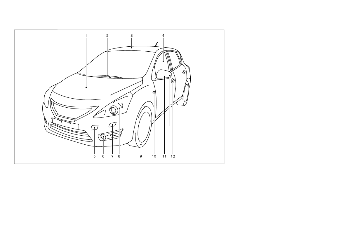
EXTERIOR FRONT
GUID-06F61144-5F27-4193-87C5-E0950EF9F755
1. Engine hood (P.3-14)
2. Windshield wiper and washer
— Switch operation (P.2-20)
— Blade replacement (P.8-15)
— Window washer fluid (P.8-17)
3. Sunroof* (P.2-24)
4. Power windows (P.2-22)
5. Recovery hook (P.6-9)
6. Fog lights*
— Switch operation (P.2-19)
10. Side turn signal lights (on the front fender or the
outside rearview mirror)
— Switch operation (P.2-19)
— Bulb replacement (P.8-24)
11. Outside mirrors (P.3-18)
12. Doors
— Keys (P.3-2)
— Door locks (P.3-3)
— Intelligent Key system* (P.3-7)
— Remote keyless entry system* (P.3-5)
— Security system* (P.3-14)
*: if equipped
JVC0429X
— Bulb replacement (P.8-24)
7. Headlight cleaners* (P.2-20)
8. Headlights and turn signal lights
— Switch operation (P.2-17)
— Bulb replacement (P.8-23)
9. Tires
— Tires and wheels (P.8-31, P.9-7)
— Flat tire (P.6-2)
— Tire placard (P.9-9)
Illustrated table of contents 0-3
Page 7
(8,1)
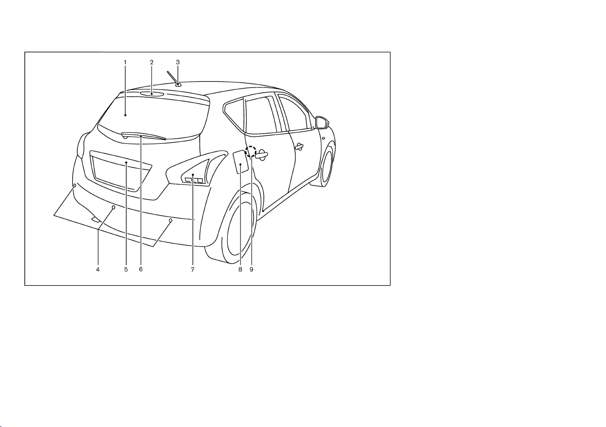
EXTERIOR REAR
GUID-E961F9FE-369F-49E4-9B87-99AC03634325
1. Rear window defogger (P.2-21)
2. High-mounted stop light (P.8-24)
3. Antenna (P.4-18)
4. Sonar (parking sensor) system* (P.5-19)
5. Back door (P.3-15)
— Intelligent Key system* (P.3-7)
— Remote keyless entry system* (P.3-5)
— Rearview camera* (P.4-2)
6. Rear window wiper and washer
— Switch operation (P.2-20)
JVC0471X
— Window washer fluid (P.8-17)
7. Rear combination lights
— Switch operation (P.2-17)
— Bulb replacement (P.8-24)
8. Fuel filler lid
— Operation (P.3-17)
— Fuel information (P.9-4)
9. Child safety rear door lock (P.3-5)
*: if equipped
0-4 Illustrated table of contents
Page 8
(9,1)
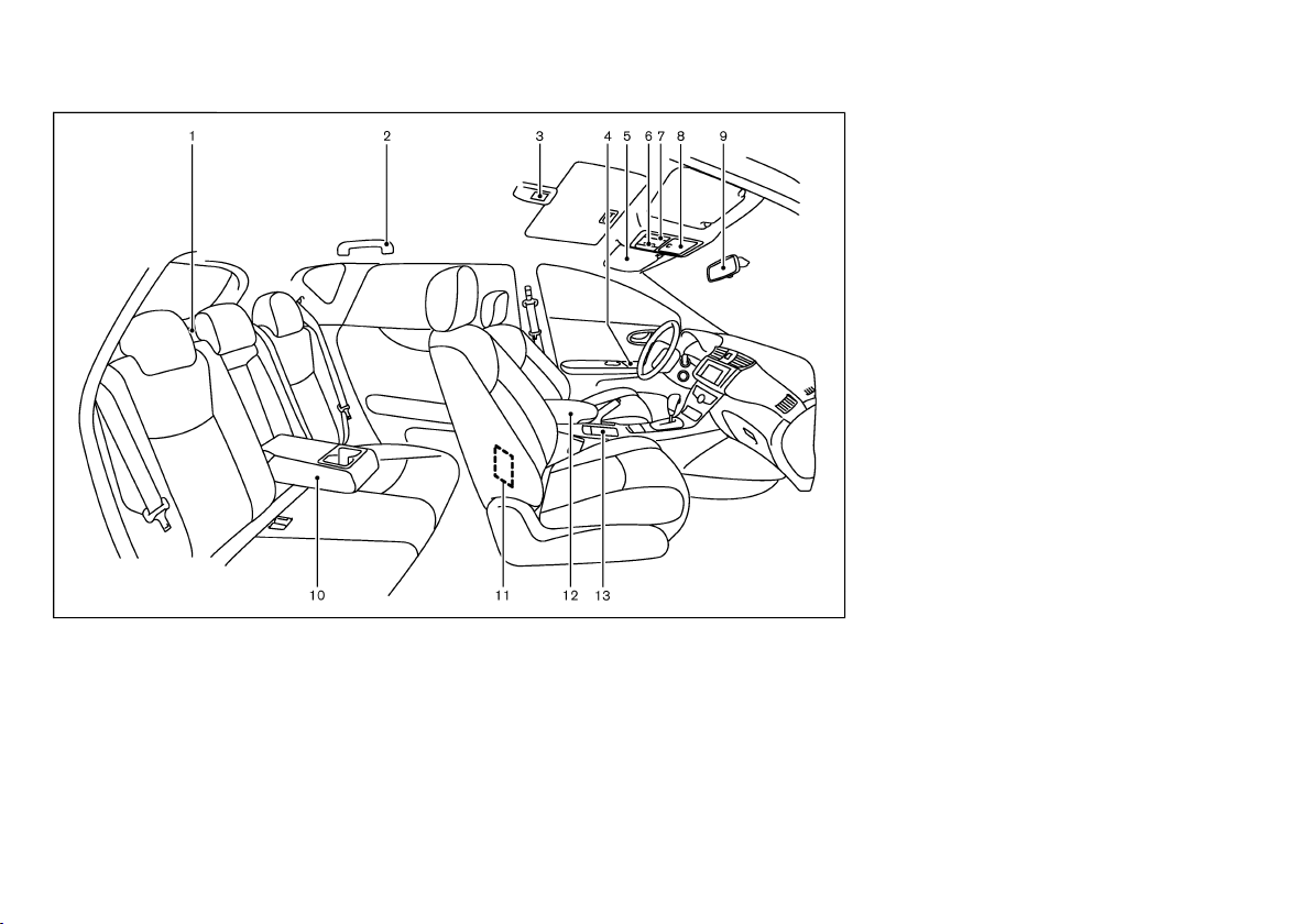
PASSENGER COMPARTMENT
GUID-A1CA6F24-0E68-4BA6-944C-91F3F2235BD3
1. Cargo cover (P.2-28)
2. Coat hook* (P.2-28)
3. Room light (P.2-29)
4. Door armrest
— Power window switch (P.2-22)
— Power door lock switch (P.3-4)
5. Sun visors (P.2-29, P.3-19)
6. Sunroof switch* (P.2-24)
7. Map lights (P.2-30)
13. Front cup holders (P.2-27)
*: if equipped
JVC0477X
8. Sunglasses holder (P.2-27)
9. Inside rearview mirror (P.3-18)
10. Rear armrest* (P.1-4)
— Rear cup holders* (P.2-27)
11. Ashtray* (P.2-25)
12. Console box (P.2-26)
- Front armrest* (P.1-4)
- USB memory operation* (P.4-25)
- iPod player operation* (P.4-26)
- USB/AUX connector* (P.4-28)
Illustrated table of contents 0-5
Page 9
(10,1)
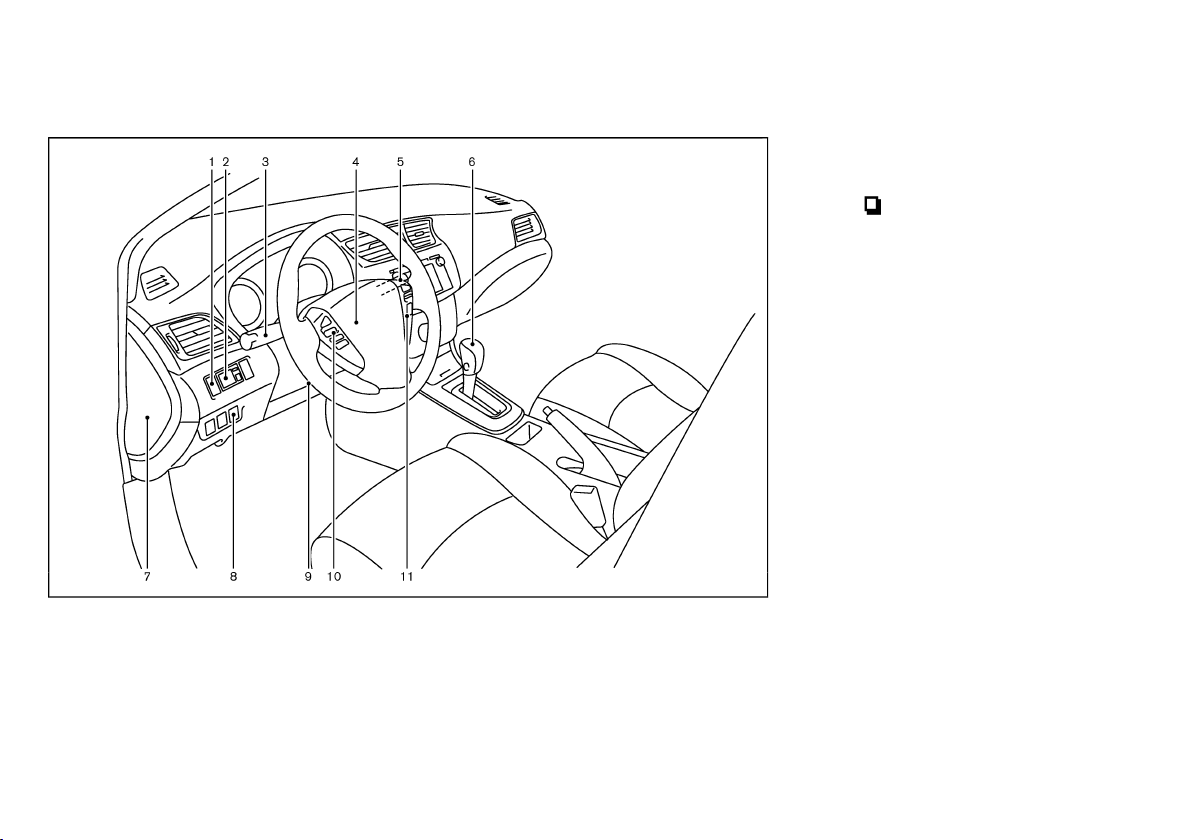
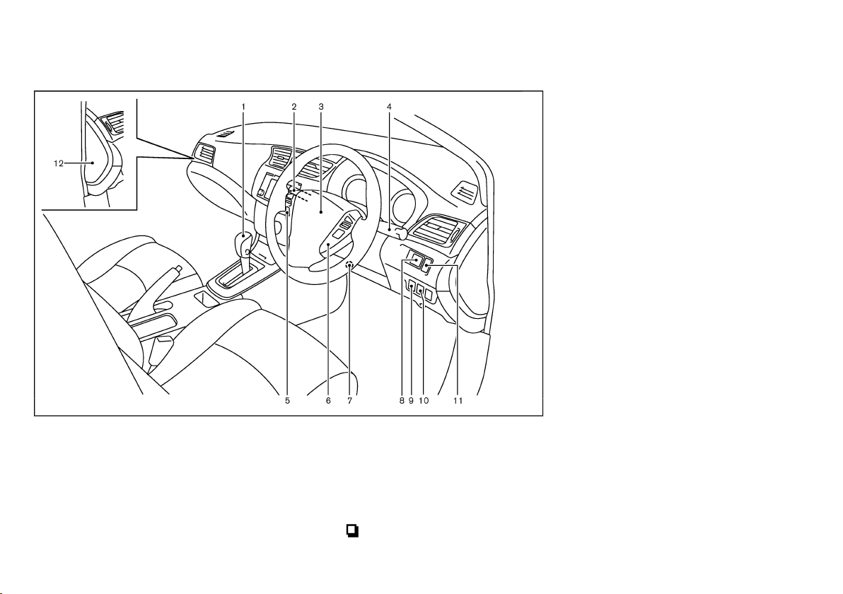
COCKPIT
GUID-4684994A-AD63-4E6A-8890-1C61156A3517
LEFT-HAND DRIVE (LHD) MODELS
GUID-9A3CAB91-CAE5-436A-BA48-04725A88B6A5
1. Instrument brightness control switch (P.2-7)
2. Outside rearview mirror control switch (P.3-18)
3. Headlight, fog light* and turn signal switch
— Headlight (P.2-17)
— Turn signal (P.2-19)
— Fog light* (P.2-19)
4. Steering wheel
— Electric power steering system (P.5-22)
— Horn (P.2-22)
— Driver’s supplemental front-impact air bag
(P.1-18)
5. Wiper and washer switch (P.2-20)
6. Shift lever
— Continuously Variable Transmission (CVT)
(P.5-9)
— Manual Transmission (MT) (P.5-13)
JVC0480X
7. Fuse box cover (P.8-22)
8. Vehicle Dynamic Control (VDC) OFF switch*
(P.5-14)
9. Tilting/telescopic steering wheel lever (P.3-17)
10. Steering-wheel-mounted controls (left side)
switch (odometer and trip computer)
—
(P.2-10)
— Audio system* (P.4-28)
— Bluetooth
out navigation system)* (P.4-29)
— Bluetooth
®
Hands-Free Phone System (with-
®
Hands-Free Phone System (with
navigation system)**
11. Steering-wheel-mounted controls (right side)
— Cruise control switches* (P.5-16)
*: if equipped
**: Refer to the separate NISSAN Connect Owner’s
Manual (if equipped).
0-6 Illustrated table of contents
Page 10
(11,1)
RIGHT-HAND DRIVE (RHD) MODELS
GUID-A5E7930B-0D66-42E4-BF05-07322329D1C5
1. Shift lever
— Continuously Variable Transmission (CVT)
(P.5-9)
— Manual Transmission (MT) (P.5-13)
2. Wiper and washer switch (P.2-20)
3. Steering wheel
— Electric power steering system (P.5-22)
— Horn (P.2-22)
JVC0437X
— Driver’s supplemental front-impact air bag
(P.1-18)
4. Headlight, fog light* and turn signal switch
— Headlight (P.2-17)
— Turn signal (P.2-19)
— Fog light* (P.2-19)
5. Steering-wheel-mounted controls (left side)
—
switch (odometer and trip computer)
(P.2-10)
— Audio system* (P.4-28)
— Bluetooth
out navigation system)* (P.4-29)
— Bluetooth
®
Hands-Free Phone System (with-
®
Hands-Free Phone System (with
navigation system)**
6. Steering-wheel-mounted controls (right side)
— Cruise control switches* (P.5-16)
7. Tilting/telescopic steering wheel lever (P.3-17)
8. Outside rearview mirror control switch (P.3-18)
9. Vehicle Dynamic Control (VDC) OFF switch*
(P.5-14)
10. Headlight aiming control switch* (P.2-18)
11. Instrument brightness control switch (P.2-7)
12. Fuse box cover (P.8-22)
*: if equipped
**: Refer to the separate NISSAN Connect Owner’s
Manual (if equipped).
Illustrated table of contents 0-7
Page 11
(12,1)
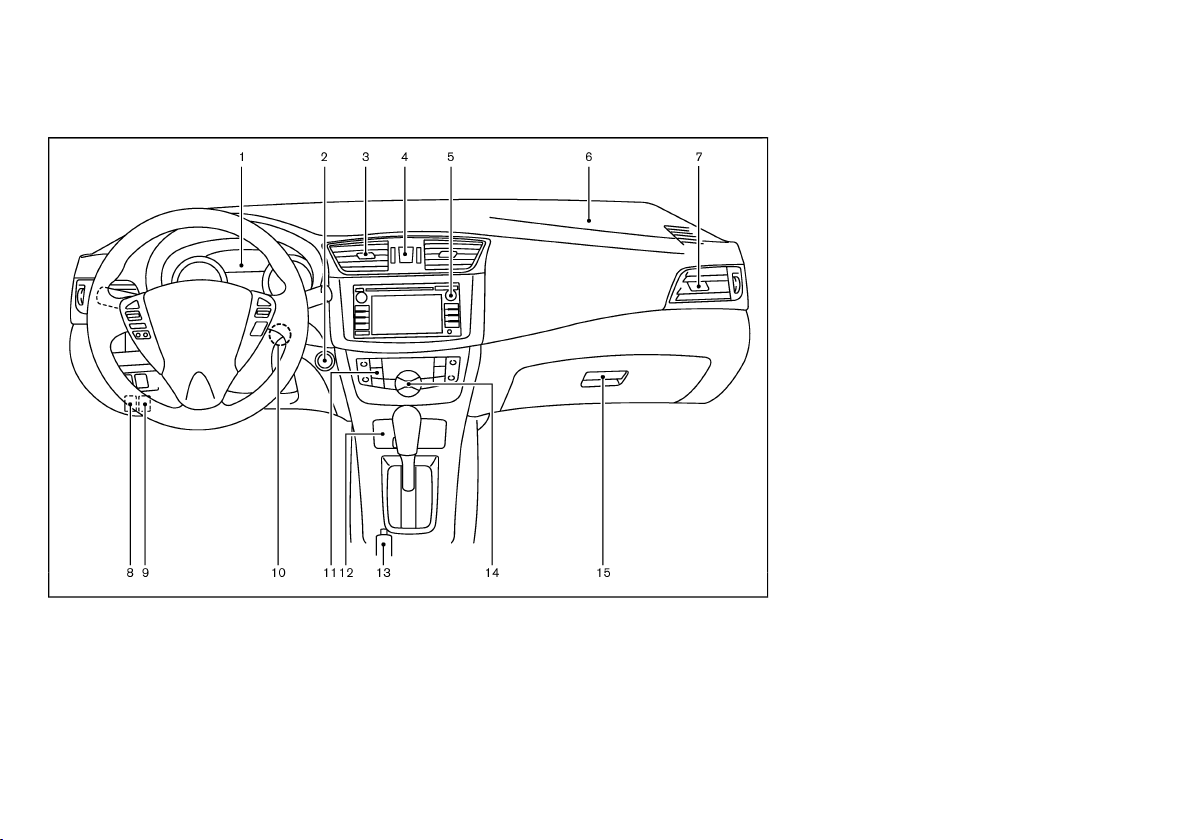
INSTRUMENT PANEL
GUID-869B8C5C-FB2C-4E37-ACFC-D7D921E63756
LEFT-HAND DRIVE (LHD) MODELS
1. Meters and gauges (P.2-6)
2. Push-button ignition switch (models with Intelligent Key system) (P.5-5)
3. Center ventilator (P.4-5)
4. Hazard indicator flasher switch (P.6-2)
5. Audio system* (P.4-11) or Navigation system**
6. Passenger’s front-impact air bag (P.1-18)
7. Side ventilator (P.4-5)
GUID-D95FEB79-F41E-4AA6-8EDC-C4DA4B58A0D0
15. Glove box (P.2-26)
*: if equipped
**: Refer to the separate NISSAN Connect Owner’s
Manual (if equipped).
JVC0307X
8. Fuel filler lid release handle (P.3-17)
9. Hood release handle (P.3-14)
10. Ignition switch (models without Intelligent Key
system) (P.5-4)
11. Defogger switch (P.2-21)
12. Ashtray and cigarette lighter (P.2-25)
13. Parking brake (P.3-19, 8-12)
14. Heater and air conditioner control (P.4-6)
0-8 Illustrated table of contents
Page 12
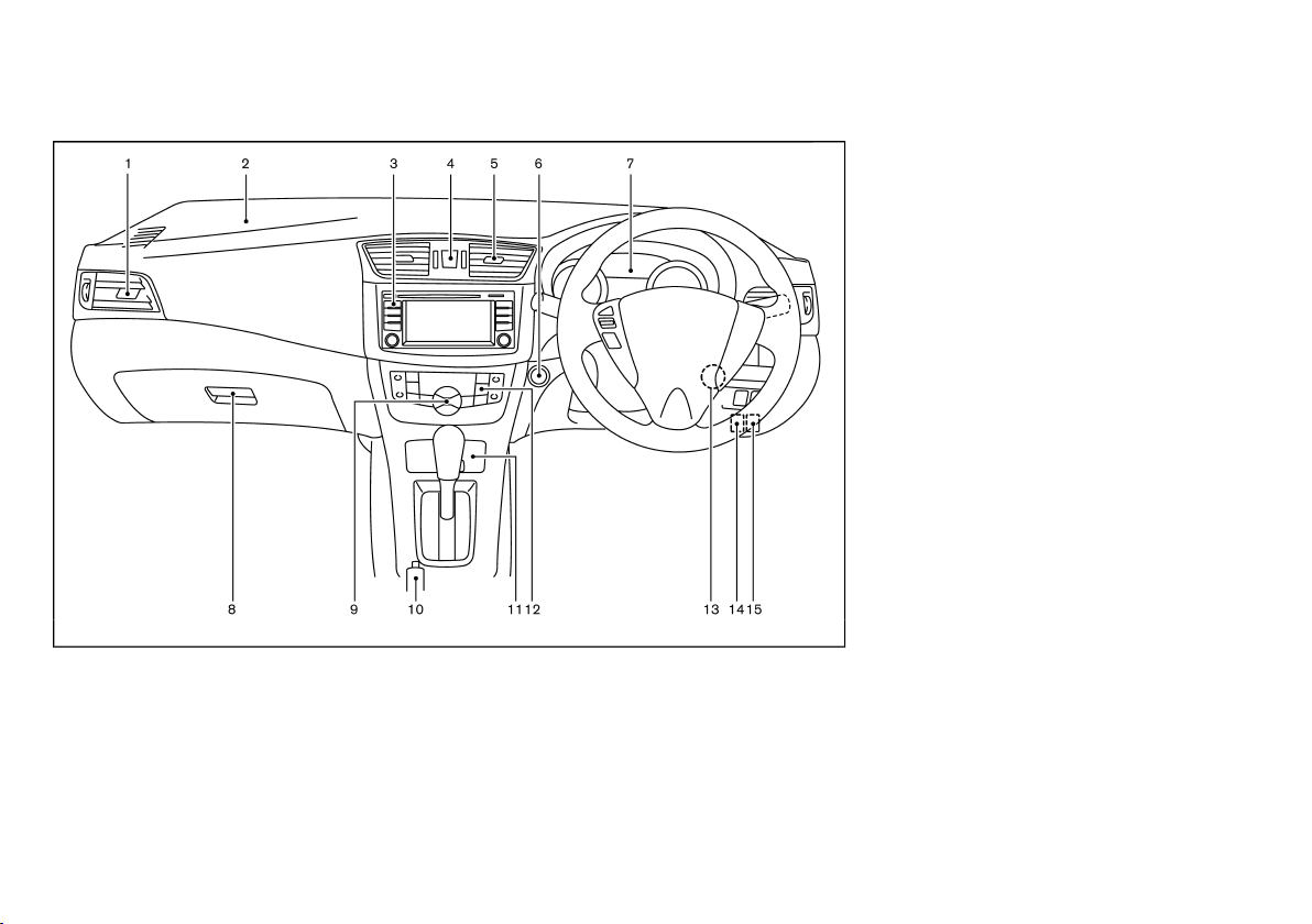
(13,1)
RIGHT-HAND DRIVE (RHD) MODELS
GUID-D11B43F4-C0AA-4C9A-8A62-2E19D5DAC1AB
1. Side ventilator (P.4-5)
2. Passenger’s front-impact air bag (P.1-18)
3. Audio system* (P.4-11) or Navigation system**
4. Hazard indicator flasher switch (P.6-2)
5. Center ventilator (P.4-5)
6. Push-button ignition switch (models with Intelligent Key system) (P.5-5)
7. Meters and gauges (P.2-6)
14. Hood release handle (P.3-14)
15. Fuel filler lid release handle (P.3-17)
*: if equipped
**: Refer to the separate NISSAN Connect Owner’s
Manual (if equipped).
JVC0306X
8. Glove box (P.2-26)
9. Heater and air conditioner control (P.4-6)
10. Parking brake (P.3-19, 8-12)
11. Power outlet* (P.2-25) or Ashtray and cigarette
lighter* (P.2-25)
12. Defogger switch (P.2-21)
13. Ignition switch (models without Intelligent Key
system) (P.5-4)
Illustrated table of contents 0-9
Page 13
(14,1)
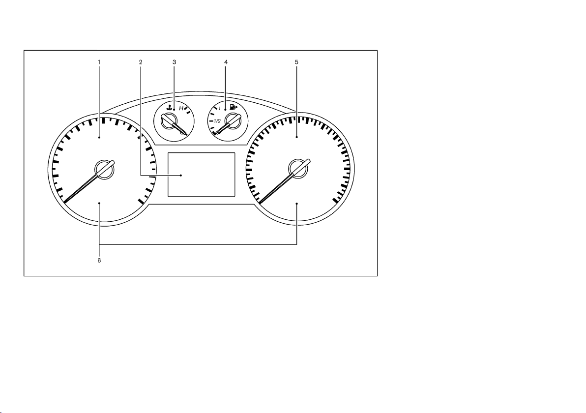
METERS AND GAUGES
GUID-088E5EE4-8597-421B-8873-FE92AA3F5ABE
1. Tachometer (P.2-6)
2. Vehicle information display (P.2-8)
— Odometer/twin trip odometer (P.2-10)
— Outside air temperature (P.2-8)
— Continuously Variable Transmission (CVT)
position indicator* (P.2-8, P.5-9)
— Trip computer (P.2-8)
3. Engine coolant temperature gauge (P.2-7)
4. Fuel gauge (P.2-7)
JVI0275X
5. Speedometer (P.2-6)
6. Warning/indicator lights (P.2-11)
*: if equipped
0-10 Illustrated table of contents
Page 14
(15,1)
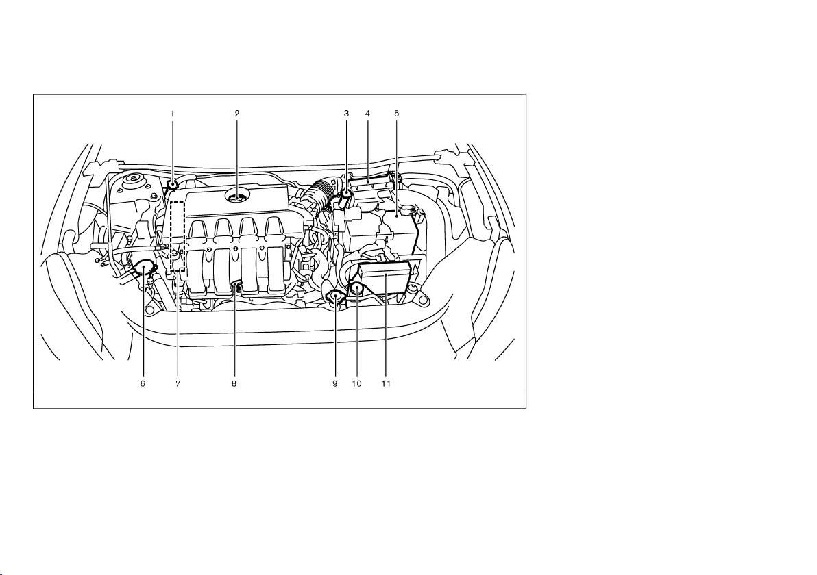
ENGINE COMPARTMENT
GUID-43A12B5B-1EC5-4B57-AF49-1F11888695D0
MRA8DE ENGINE MODEL
1. Brake and clutch* fluid reservoir (P.8-13)
— Right-Hand Drive (RHD) models
2. Engine oil filler cap (P.8-9)
3. Brake fluid reservoir (P.8-13)
— Left-Hand Drive (LHD) models
4. Air cleaner (P.8-15)
5. Battery (P.8-18)
— Jump starting (P.6-5)
GUID-6E1DA810-4A38-406B-8F9B-5641920A43EF
JVC0363X
6. Window washer fluid reservoir (P.8-17)
7. Engine drive belt location (P.8-11)
8. Engine oil dipstick (P.8-9)
9. Radiator cap (P.8-7)
— Vehicle overheat (P.6-7)
10. Engine coolant reservoir (P.8-7)
11. Fuse/fusible link holders (P.8-21)
*: For Manual Transmission (MT) models
Illustrated table of contents 0-11
Page 15
(16,1)
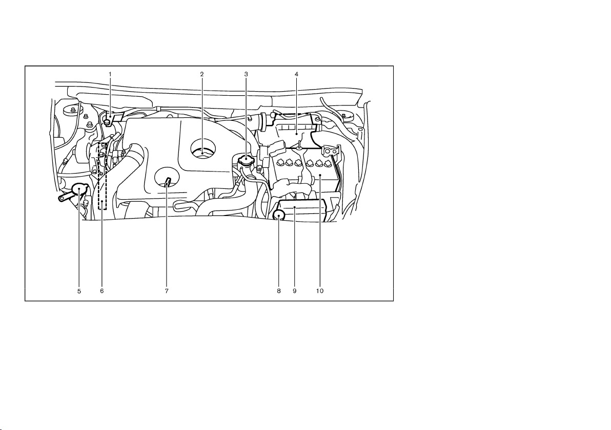
MR16DDT ENGINE MODEL
1. Brake and clutch* fluid reservoir (P.8-13)
2. Engine oil filler cap (P.8-9)
3. Radiator cap (P.8-7)
— Vehicle overheat (P.6-7)
4. Air cleaner (P.8-15)
5. Window washer fluid reservoir (P.8-17)
6. Engine drive belt location (P.8-11)
7. Engine oil dipstick (P.8-9)
GUID-D8B2D2C0-7E46-4A8F-915F-A7C17E8386F2
JVM0262X
8. Engine coolant reservoir (P.8-7)
9. Fuse/fusible link holders (P.8-21)
10. Battery (P.8-18)
— Jump starting (P.6-5)
*: For Manual Transmission (MT) model
0-12 Illustrated table of contents
Page 16

(17,1)
HR16DE ENGINE MODEL
GUID-DCE84F59-875A-4CF0-84D3-EDA6A831E16D
1. Brake and clutch* fluid reservoir (P.8-13)
— Right-Hand Drive (RHD) models
2. Engine oil filler cap (P.8-9)
3. Brake and clutch* fluid reservoir (P.8-13)
— Left-Hand Drive (LHD) models
4. Air cleaner (P.8-15)
5. Battery (P.8-18)
— Jump starting (P.6-5)
JVC0364X
6. Window washer fluid reservoir (P.8-17)
7. Engine drive belt location (P.8-11)
8. Engine oil dipstick (P.8-9)
9. Radiator cap (P.8-7)
— Vehicle overheat (P.6-7)
10. Engine coolant reservoir (P.8-7)
11. Fuse/fusible link holders (P.8-21)
*: For Manual Transmission (MT) models
Illustrated table of contents 0-13
Page 17

(18,1)
MEMO
0-14 Illustrated table of contents
Page 18

(19,1)
1 Safety — seats, seat belts and supplemental
restraint system
Seats ............................................................................................................... 1-2
Front seats .............................................................................................. 1-2
Rear seats ............................................................................................... 1-3
Armrest .................................................................................................... 1-4
Head restraints ............................................................................................. 1-5
Adjustable head restraint .................................................................... 1-5
Non-adjustable head restraint ........................................................... 1-5
Remove .................................................................................................... 1-5
Install ........................................................................................................ 1-6
Adjust ....................................................................................................... 1-6
Seat belts ...................................................................................................... 1-7
Precautions on seat belt usage ........................................................ 1-7
Child safety ............................................................................................. 1-8
Pregnant women ................................................................................... 1-9
Injured persons ...................................................................................... 1-9
Center mark on seat belts .................................................................. 1-9
Three-point type seat belts .............................................................. 1-9
Two-point type seat belts (if equipped) .................................... 1-11
Seat belt maintenance ................................................................... 1-11
Child restraints ......................................................................................... 1-12
Precautions on child restraint usage .......................................... 1-12
Child restraint anchorage (if equipped) .................................... 1-12
Child restraint installation using 3-point type seat belt
(if equipped) ..................................................................................... 1-13
Child restraint installation using 2-point type seat belt
(if equipped) ..................................................................................... 1-16
Supplemental Restraint System (SRS) .............................................. 1-18
Precautions on Supplemental Restraint System (SRS) ........ 1-18
Supplemental air bag systems ..................................................... 1-22
SRS air bag deployment conditions ........................................... 1-24
Pre-tensioner seat belt system (if equipped) ........................... 1-26
Repair and replacement procedure ............................................ 1-26
Page 19
(20,1)
SEATS
GUID-65E1CF4D-248A-4E0E-B80E-0E67876FCCD6
SSS0133A
WARNING:
. Do not drive and/or ride in the vehicle with
the seatback reclined. This can be dangerous. The shoulder belt will not be properly
against the body. In an accident, you and
your passengers could be thrown into the
shoulder belt and receive neck or other
serious injuries. You and your passengers
could also slide under the lap belt and
receive serious injuries.
. For the most effective protection while the
vehicle is in motion, the seatback should be
upright. Always sit well back in the seat and
adjust the seat belt properly. (See “Seat
belts” (P.1-7).)
FRONT SEATS
Do not adjust the driver’s seat while driving so
that full attention may be given to vehicle
operation.
Manual seat adjustment
After adjusting a seat, gently shake the seat to
confirm that the seat is locked securely. If the
seat is not locked securely, it may move
suddenly and could cause the loss of control of
the vehicle.
GUID-EA19C552-8EF1-470D-8CB3-CAABA9F21446
WARNING:
GUID-E5A26E75-3DD6-4E76-AA24-3DBFA97F9F4B
WARNING:
CAUTION:
When adjusting the seat positions, be sure not
to contact any moving parts to avoid possible
injuries and/or damages.
1-2 Safety — seats, seat belts and supplemental restraint system
Page 20
(21,1)
Forward and backward:
1. Pull up the adjusting lever
GUID-9E14C2E6-2E9C-4731-980B-C45B899B977B
1
.
*
2. Slide the seat to the desired position.
3. Release the adjusting lever to lock the seat in
position.
Reclining:
1. Pull up the adjusting lever
GUID-9E14C2E6-2E9C-4731-980B-C45B899B977B
2
.
*
2. Tilt the seatback to the desired position.
3. Release the adjusting lever to lock the seatback in
position.
The reclining feature allows the adjustment of the
seatback for occupants of different sizes to help obtain
the proper seat belt fit. (See “Seat belts” (P.1-7).)
The seatback may be reclined to allow occupants to
rest when the vehicle is parked.
SSS0792
Seat lifter (if equipped):
GUID-9E14C2E6-2E9C-4731-980B-C45B899B977B
SSS1129
Pull up or push down the adjusting lever to adjust the
seat height until the desired position is achieved.
REAR SEATS
Folding
Before folding the rear seats:
Secure the seat belts on the seat belt hooks on the
GUID-A95A1654-09D4-44BC-89C1-C253B6CC3D14
GUID-1776AFB3-BD79-41D2-B498-D7CAC47A8A6B
SSS1145
GUID-9E14C2E6-2E9C-4731-980B-C45B899B977B
side wall. (See “Seat belt hooks” (P.1-10).)
To fold the seatback, pull the adjusting knob
1
.
*
To return the seatback to the seating position, lift up
each seatback and push it to the upright position until
it is latched.
CAUTION:
When folding or returning the seatback(s) to the
upright position, make sure that the seat path is
clear before moving the seat to avoid injury to
yourself and others.
WARNING:
. Never allow anyone to ride in the luggage
area or on the rear seats when they are in
the fold-down position. Use of these areas
by passengers without proper restraints
could result in serious injury in an accident
Safety — seats, seat belts and supplemental restraint system 1-3
Page 21
(22,1)
or sudden stop.
. Do not fold down the rear seats when
occupants are in the rear seat area or any
luggage is on the rear seats.
. Properly secure all luggage to help prevent it
from sliding or shifting. Do not place luggage higher than the seatbacks.
. When returning the seatbacks to the upright
position, be certain they are completely
secured in the latched position. If they are
not completely secured, passengers may be
injured in an accident or sudden stop.
. Head restraints should be adjusted properly
as they may provide significant protection
against whiplash injury. Always replace and
adjust them properly if they have been
removed for any reason.
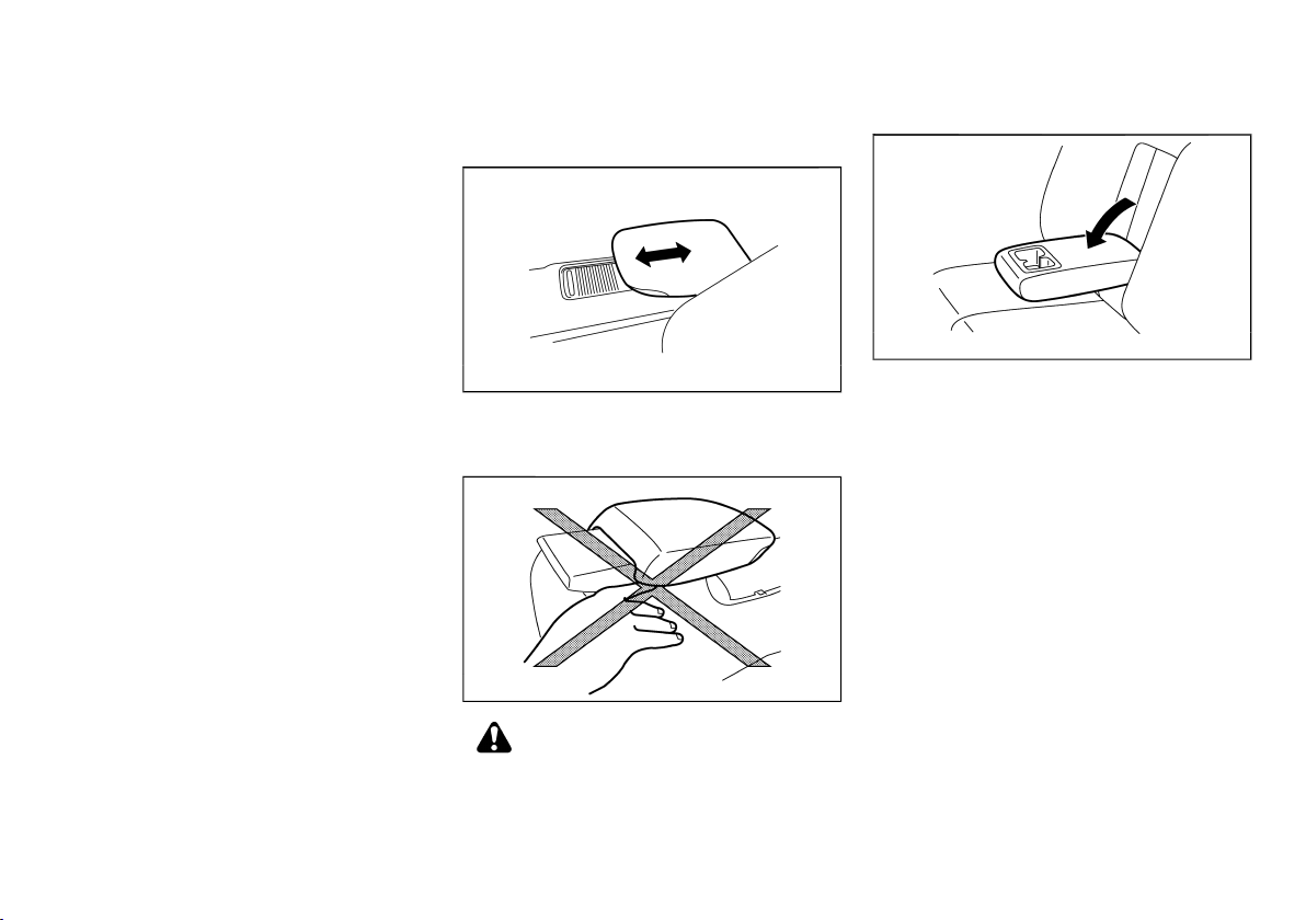
ARMREST
Front
GUID-403C964A-AB99-4CBE-97C9-20E36AA8A07E
GUID-116F0D1F-2BF9-4B1A-AEC8-6A38242B8071
JVR0118X
To use the front armrest, slide it forward.
Slide the armrest to the original position when using
the front cup holders.
JVR0042X
CAUTION:
When the front armrest is in the forward-most
position, do not place your fingers on the bottom
portion of the armrest to avoid possible injuries.
Your fingers could be injured if the armrest
slides to its original position.
Rear (if equipped)
GUID-98AB7A5D-36C0-4EF1-B4E6-CE0EC7D788CB
Pull the armrest forward until it is horizontal.
SIC4593
1-4 Safety — seats, seat belts and supplemental restraint system
Page 22
(23,1)
HEAD RESTRAINTS
GUID-1D2DB560-F0D1-4E17-A618-221460107213
WARNING:
Head restraints supplement the other vehicle
safety systems. They may provide additional
protection against injury in certain rear end
collisions. Adjustable head restraints must be
adjusted properly, as specified in this section.
Check the adjustment after someone else uses
the seat. Do not attach anything to the head
restraint stalks or remove the head restraint. Do
not use the seat if the head restraint has been
removed. If the head restraint was removed,
reinstall and properly adjust the head restraint
before an occupant uses the seating position.
Failure to follow these instructions can reduce
the effectiveness of the head restraint. This may
increase the risk of serious injury or death in a
collision.
. Your vehicle is equipped with a head restraint that
may be integrated, adjustable or non-adjustable.
. Adjustable head restraints have multiple notches
along the stalk to lock them in a desired
adjustment position.
. The non-adjustable head restraints have a single
locking notch to secure them to the seat frame.
. Proper Adjustment:
— For the adjustable type, align the head restraint
so the center of your ear is approximately level
with the center of the head restraint.
— If your ear position is still higher than the
recommended alignment, place the head
restraint at the highest position.
. If the head restraint has been removed, ensure
that it is reinstalled and locked in place before
riding in that designated seating position.
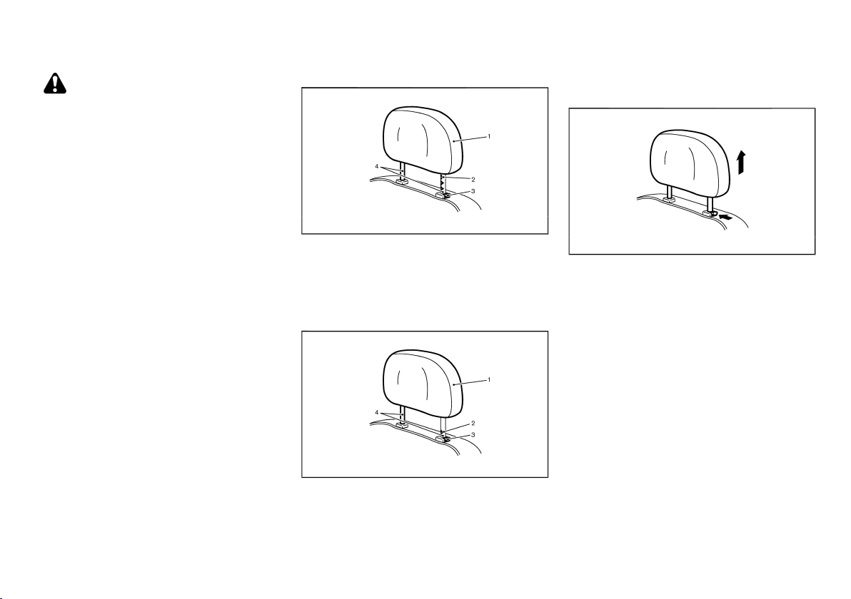
ADJUSTABLE HEAD RESTRAINT
GUID-6C88D4AC-5493-4D7E-A8B2-5C0BA789C719
SSS0992
1. Removable head restraint
2. Multiple notches
3. Lock knob
4. Stalks
NON-ADJUSTABLE HEAD RESTRAINT
GUID-1EB1A16B-94AC-4529-82EA-BEC9EB4F3D4A
JVR0203X
1. Removable head restraint
2. Single notch
3. Lock knob
4. Stalks
REMOVE
GUID-290925FB-6436-4FF1-9E3D-7ED53BDC5322
SSS1037
Use the following procedure to remove the head
restraint.
1. Pull the head restraint up to the highest position.
2. Push and hold the lock knob.
3. Remove the head restraint from the seat.
4. Store the head restraint properly in a secure place
so it is not loose in the vehicle.
5. Reinstall and properly adjust the head restraint
before an occupant uses the seating position.
Safety — seats, seat belts and supplemental restraint system 1-5
Page 23
(24,1)
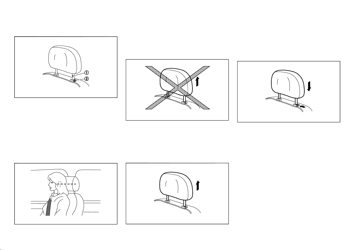
INSTALL
GUID-73A81482-05DF-4DF7-B2C4-2E27EA6245FD
SSS1038
1. Align the head restraint stalks with the holes in the
seat. Make sure that the head restraint is facing
the correct direction. The stalk with the adjustment
1
notch
lock knob
must be installed in the hole with the
*
2
.
*
2. Push and hold the lock knob and push the head
restraint down.
3. Properly adjust the head restraint before an
occupant uses the seating position.
ADJUST
GUID-9E1F43B9-8B6D-4575-9B2E-4EFB399EE3DA
For adjustable head restraint
Adjust the head restraint so the center is level with the
center of your ears. If your ear position is still higher
than the recommended alignment, place the head
restraint at the highest position.
JVR0259X
For non-adjustable head restraint
Make sure the head restraint is positioned from the
stored position or any non-latch position so the lock
knob is engaged in the notch before riding in that
designated seating position.
Raise
GUID-381E3681-A0D7-4BA9-99AB-F3036FA3C573
Make sure the head restraint is positioned from the
stored position or any non-latch position so the lock
knob is engaged in the notch before riding in that
designated seating position.
Lower
GUID-7009499C-CED8-4CB8-99B7-1F53EBF13F41
SSS1036
To lower, push and hold the lock knob and push the
head restraint down.
Make sure the head restraint is positioned so the lock
knob is engaged in the notch before riding in that
designated seating position.
SSS0997
To raise the head restraint, pull it up.
1-6 Safety — seats, seat belts and supplemental restraint system
SSS1035
Page 24
(25,1)
SEAT BELTS
GUID-B24797EF-9596-4C08-A632-05BD45FC2BE9
PRECAUTIONS ON SEAT BELT USAGE
If you are wearing the seat belt properly adjusted and
sitting upright and well back in the seat, chances of
being injured or killed in an accident and/or the severity
of injury may be greatly reduced. NISSAN strongly
encourages you and all of your passengers to buckle
up every time you drive, even if your seating position
includes the supplemental air bag systems.
GUID-7E5A0FD7-D295-4EFD-A08C-C72A17D14624
SSS0134A
SSS0136A
SSS0014 SSS0016
Safety — seats, seat belts and supplemental restraint system 1-7
Page 25

(26,1)
WARNING:
. Seatbelts are designed to bear upon the
bony structure of the body, and should be
worn low across the front of the pelvis or the
pelvis, chest and shoulders, as applicable;
wearing the lap section of the belt across
the abdominal area must be avoided. Serious injury may occur if a seat belt is not
worn properly.
. Position the lap belt as low and snug as
possible around the hips, not the waist. A
lap belt worn too high could increase the
risk of internal injuries in an accident.
. Do not allow more than one person to use
the same seat belt. Each belt assembly must
only be used by one occupant; it is dangerous to put a belt around a child being carried
on the occupant’s lap.
. Never carry more people in the vehicle than
there are seat belts.
. Never wear seat belts inside out. Belts
should not be worn with straps twisted.
Doing so may reduce their effectiveness.
. Seatbelts should be adjusted as firmly as
possible, consistent with comfort, to provide
the protection for which they have been
designed. A slack belt will greatly reduce the
protection afforded to the wearer.
. Every person who drives or rides in this
vehicle should use a seat belt at all times.
Children should be properly restrained in the
rear seat and, if appropriate, in a child
restraint system.
. Do not run the belt behind your back or
under your arm. Always route the shoulder
belt over your shoulder and across your
chest. The belt should be away from your
face and neck, but not falling off your
shoulder. Serious injury may occur if a seat
belt is not worn properly.
. No modifications or additions should be
made by the user which will either prevent
the seat belt adjusting devices from operating to remove slack, or prevent the seat belt
assembly from being adjusted to remove
slack.
. Care should be taken to avoid contamina-
tion of the webbing with polishes, oils and
chemicals, and particularly battery acid.
Cleaning may safely be carried out using
mild soap and water. The belt should be
replaced if webbing becomes frayed, contaminated or damaged.
. All seat belt assemblies including retractors
and attaching hardware should be inspected
after any collision by a NISSAN dealer.
NISSAN recommends that all seat belt
assemblies in use during a collision be
replaced unless the collision was minor
and the belts show no damage and continue
to operate properly. Seat belt assemblies
not in use during a collision should also be
inspected and, when necessary, replaced if
either damage or improper operation is
noted.
. It is essential to replace the entire assembly
after it has been worn in a severe impact
even if damage to the assembly is not
obvious.
. Once the pre-tensioner seat belt (if
equipped) has activated, it cannot be reused.
It must be replaced together with the
retractor. Contact a NISSAN dealer.
. Removal and installation of the pre-ten-
sioner seat belt system components (if
equipped) should be done by a NISSAN
dealer.
CHILD SAFETY
GUID-50FE0FCD-DBC6-4BF8-A13A-E3AFA74EB719
WARNING:
. Infants and children need special protection.
The vehicle’s seat belts may not fit them
properly. The shoulder belt may come too
close to the face or neck. The lap belt may
not fit over their small hipbones. In an
accident, an improperly fitted seat belt could
cause serious or fatal injury.
. Always use an appropriate child restraint
system.
Children need adults to help protect them. They need
to be properly restrained. The proper restraint depends
on the child’s size.
1-8 Safety — seats, seat belts and supplemental restraint system
Page 26
(27,1)
Infants and small children
GUID-9EA9FF02-4615-4E08-8998-8897493078B8
SSS0099
NISSAN recommends that infants and small children
be seated in a child restraint system. You should
choose a child restraint system that fits your vehicle
and the child, and always follow the manufacturer’s
instructions for installation and use.
Large children
GUID-7EC09A67-00D1-4A31-9107-8BC52BC8A5CE
WARNING:
. Never allow children to stand or kneel on
any seats.
. Never allow children in the cargo areas while
the vehicle is moving. A child could be
seriously injured in an accident or sudden
stop.
Children who are too large for a child restraint system
should be seated and restrained by the seat belts that
are provided.
If the child’s seating position has a shoulder belt that
fits close to the face or neck, the use of a booster seat
(commercially available) may help overcome this. The
booster seat should raise the child so that the shoulder
belt is properly positioned across the top, middle
portion of the shoulder and the lap belt is low on the
hips. The booster seat should also fit the vehicle seat.
Once the child has grown so that the shoulder belt is
no longer on or near the face or neck of the child, use
the shoulder belt without the booster seat. In addition,
there are many types of child restraint systems
available for larger children that should be used for
maximum protection.
PREGNANT WOMEN
NISSAN recommends that pregnant women use seat
GUID-EB362D86-544D-4564-AF14-2AA962BFFC63
belts. The seat belt should be worn snug, and always
position the lap belt as low as possible around the
hips, not the waist. Place the shoulder belt over your
shoulder and across your chest. Never run the lap/
shoulder belt over your abdominal area. Contact your
doctor for specific recommendations.
INJURED PERSONS
NISSAN recommends that injured persons use seat
GUID-11687DB4-061D-4F49-9F66-C8C24C9C8A28
belts. Contact your doctor for specific recommendations.
CENTER MARK ON SEAT BELTS
Selecting correct set of seat belts
GUID-4379FCB6-A0FC-49F8-B357-9DDABA29EF87
GUID-D44FE812-A107-4F66-B3D5-9588A17259FA
JVR0041X
The center seat belt buckle and the tongue are
identified by the CENTER mark. The center seat belt
tongue can be fastened only into the center seat belt
buckle.
THREE-POINT TYPE SEAT BELTS
GUID-0BC1986B-C5D8-4503-B446-845D468C8DFE
SSS0292
WARNING:
Every person who drives or rides in this vehicle
should use a seat belt at all times.
Safety — seats, seat belts and supplemental restraint system 1-9
Page 27

(28,1)
Fastening seat belts
GUID-89F085F0-308A-481D-A480-9ED347F5EEA1
WARNING:
The seatback should not be in a reclined
position any more than needed for comfort. Seat
belts are most effective when the passenger sits
4. Pull the shoulder belt portion toward the retractor
to take up extra slack. Be sure the shoulder belt is
routed over your shoulder and is snug across your
chest.
Shoulder belt height adjustment (front seats)
GUID-3C34CDBB-BB30-4CBB-99BE-2387B7C1E699
well back and straight up in the seat.
1. Adjust the seat. (See “Seats” (P.1-2).)
2. Slowly pull the seat belt out of the retractor and
insert the tongue into the buckle until you hear and
feel the latch engage.
.
The retractor is designed to lock during a
sudden stop or on impact. A slow pulling
motion permits the seat belt to move, and
allows you some freedom of movement in
the seat.
.
If the seat belt cannot be pulled from its
fully retracted position, firmly pull the belt
and release it. Then smoothly pull the belt
out of the retractor.
. The shoulder belt anchor height should be
WARNING:
adjusted to the position best for you. Failure
to do so may reduce the effectiveness of the
entire restraint system and increase the
chance or severity of injury in an accident.
. The shoulder belt should rest on the middle
of the shoulder. It must not rest against the
neck.
. Be sure that the seat belt is not twisted in
any way.
. Be sure that the shoulder belt anchor is
SSS0467
3. Position the lap belt portion low and snug on the
hips as shown.
secured by trying to move the shoulder belt
anchor up and down after adjustment.
The shoulder belt anchor height should be adjusted to
the position best for you.
The belt should be away from your face and neck, but
1-10 Safety — seats, seat belts and supplemental restraint system
SSS0351A
not falling off your shoulder.
1
To adjust, pull the release button
shoulder belt anchor to the proper position
and move the
*
2
*
, so that
the belt passes over the center of the shoulder.
Release the button to lock the shoulder belt anchor
into position.
Unfastening seat belts
Push the button on the buckle. The seat belt
GUID-B9FD6826-2EEF-4B6A-BBB2-8DA9DC9A114C
automatically retracts.
Seat belt hooks
GUID-0A7B1C10-9CFD-4887-B9D3-AF0EDDB1D238
SSS1138
When the rear seat belts are not in use and when
folding down the rear seats, hook the rear outer seat
belts on the seat belt hooks.
Checking seat belt operation
Seat belt retractors are designed to lock seat belt
GUID-403EE7BD-2595-4C9C-B3EC-2256E3EF91C8
movement:
. When the seat belt is pulled quickly from the
retractor.
. When the vehicle slows down rapidly.
To increase your confidence in the seat belts, check
the operation by grasping the shoulder belt and pulling
forward quickly. The retractor should lock and restrict
Page 28
(29,1)
further belt movement. If the retractor does not lock
during this check, contact a NISSAN dealer immediately.
TWO-POINT TYPE SEAT BELTS (if
equipped)
Fastening seat belts
Seat belts are most effective when the passenger sits well back and straight up in the seat.
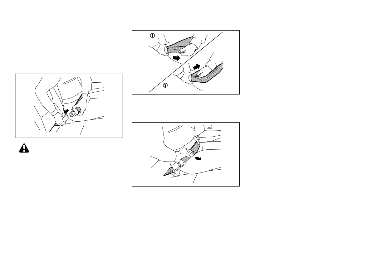
1. Insert the tongue into the buckle marked CENTER
until you hear and feel the latch engage.
GUID-529803C3-7237-429A-B395-21C4724BFEA1
GUID-4E3A86C9-2C5C-4948-B0A8-7998841C1CDE
JVR0035X
WARNING:
JVR0036X
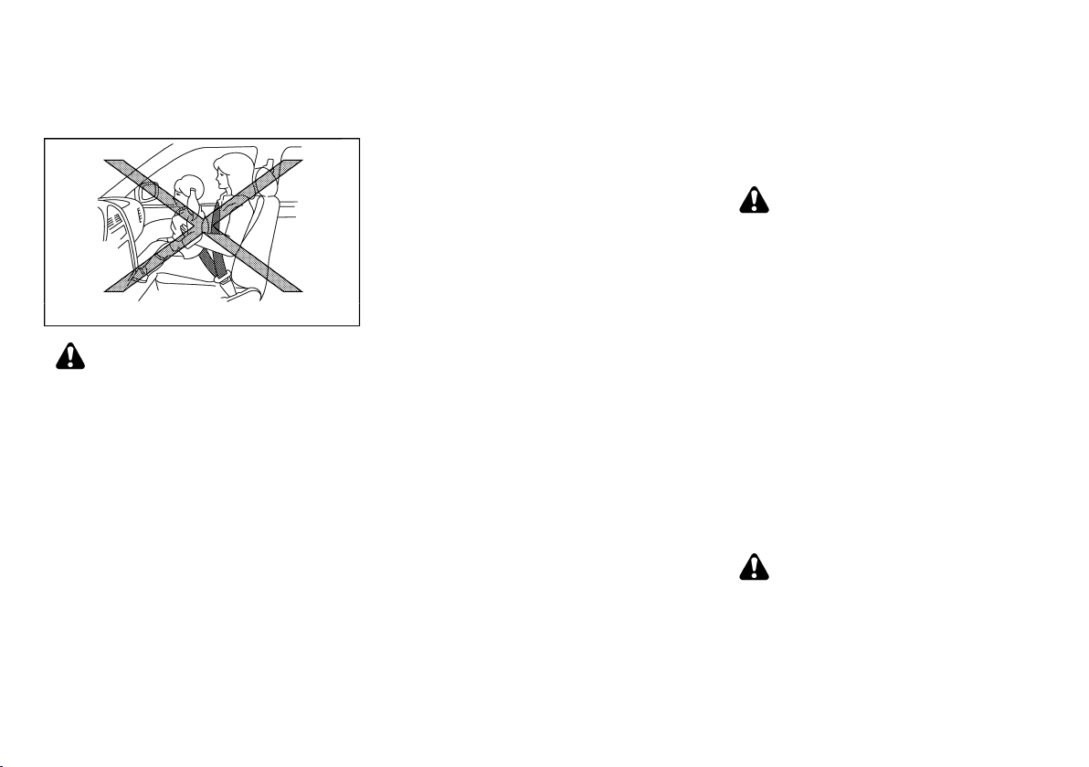
2. Adjust the seat belt length. To shorten, hold the
tongue and pull the upper belt as illustrated
1
*
To lengthen, hold the tongue and pull the under
belt as illustrated
2
.
*
JVR0037X
3. Position the lap belt portion low and snug on the
hips as shown.
Unfastening seat belts
Push the button on the buckle.
SEAT BELT MAINTENANCE
Periodically check that the seat belt and all the metal
GUID-B678EAF0-A08C-4DF6-BC72-45BFD830E250
GUID-1C0BBCBB-C6A2-4E79-BD2C-4BF0F58A6E61
components, such as buckles, tongues, retractors,
flexible wires and anchors, work properly. If loose parts,
deterioration, cuts or other damage on the seat belt
webbing is found, the entire seat belt assembly should
be replaced.
If dirt builds up in the shoulder belt guide of the seat
belt anchors, the seat belts may retract slowly. Wipe
the shoulder belt guide with a clean, dry cloth.
.
To clean the seat belt webbing, apply a mild soap
solution or any solution recommended for cleaning
upholstery or carpet. Then wipe with a cloth and allow
the seat belts to dry in the shade. Do not allow the seat
belts to retract until they are completely dry.
Safety — seats, seat belts and supplemental restraint system 1-11
Page 29
(30,1)
CHILD RESTRAINTS
GUID-F2068D73-379A-46BC-9200-AB7FD98E9DCB
PRECAUTIONS ON CHILD RESTRAINT
USAGE
. Infants and small children should always be
placed in an appropriate child restraint while
riding in the vehicle. Failure to use a child
restraint can result in serious injury or death.
. Infants and small children should never be
carried on your lap. It is not possible for even
the strongest adult to resist the forces of a
severe accident. The child could be crushed
between the adult and parts of the vehicle.
Also, do not put the same seat belt around
both your child and yourself.
. NISSAN recommends that the child re-
straints be installed in the rear seat. According to accident statistics, children are safer
when properly restrained in the rear seat
than in the front seat.
. Improper use or improper installation of a
child restraint can increase the risk or
severity of injury for both the child and other
occupants of the vehicle and can lead to
1-12 Safety — seats, seat belts and supplemental restraint system
GUID-843A7C9C-1266-4B11-9B92-C7AD768A370E
SSS0099
WARNING:
serious injury or death in an accident.
. Follow all of the child restraint manufac-
turer’s instructions for installation and use.
When purchasing a child restraint, be sure to
select one which will fit your child and
vehicle. It may not be possible to properly
install some types of child restraint in your
vehicle.
. The direction of the child restraint, either
front-facing or rear-facing, depends on the
type of the child restraint and the size of the
child. Refer to the child restraint manufacturer’s instructions for details.
. Adjustable seatbacks should be positioned
to fit the child restraint, but as upright as
possible.
. After attaching a child restraint, test it
before you place the child in it. Push it from
side to side and tug it forward to make sure
that it is held securely in place. The child
restraint should not move more than 25 mm
(1 in). If the restraint is not secure, tighten
the belt as necessary, or install the restraint
in another seat and test it again.
. When the child restraint is not in use, keep it
secured with a seat belt to prevent it from
being thrown around in case of a sudden
stop or accident.
. Never install a rear-facing child restraint on
the front passenger’s seat when the front
passenger’s air bag is available. Supplemental front-impact air bags inflate with
great force. A rear-facing child restraint
could be struck by the supplemental frontimpact air bags in an accident and could
seriously injure or kill your child.
. If the seat belt in the position where a child
restraint is installed requires a locking
device and if it is not used, injuries could
result from a child restraint tipping over
during normal vehicle braking or cornering.
CAUTION:
Remember that a child restraint left in a closed
vehicle can become very hot. Check the seating
surface and buckles before placing your child in
a child restraint.
NISSAN recommends that infants and small children
be seated in a child restraint. You should choose a
child restraint that fits your vehicle and always follow
the manufacturer’s instructions for installation and use.
In addition, there are many types of child restraints
available for larger children that should be used for
maximum protection.
CHILD RESTRAINT ANCHORAGE (if
equipped)
Your vehicle is designed to accommodate a child
restraint system on the rear seat. When installing a
child restraint system, carefully read and follow the
instructions in this manual and those supplied with the
child restraint system.
. Child restraint anchorages are designed to
withstand only those loads imposed by
correctly fitted child restraints. Under no
circumstances are they to be used for adult
seat belts, harnesses or for attaching other
items or equipment to the vehicle. Doing so
could damage the child restraint anchorages. The child restraint will not be
GUID-999EF414-BA0B-4E48-86C4-F6A14C27D2DC
WARNING:
Page 30
(31,1)
properly installed using the damaged anchorage, and a child could be seriously
injured or killed in a collision.
. The child restraint top tether strap may be
damaged by contact with the cargo cover or
items in the luggage area. Remove the cargo
cover from the vehicle or secure it and any
luggage. Your child could be seriously
injured or killed in a collision if the top
tether strap is damaged.
CHILD RESTRAINT INSTALLATION USING
3-POINT TYPE SEAT BELT (if equipped)
Installation on rear outer seats
GUID-88B65913-C497-4813-85DA-387E04EA1320
GUID-BD49434F-1329-4217-B13F-291E826C3ED4
2. Route the seat belt tongue through the child
restraint and insert it into the buckle
*
2
until you
hear and feel the latch engage.
3. To prevent slack in the seat belt webbing, it is
necessary to secure the seat belt in place with
locking devices attached to the child restraint.
Anchorage location
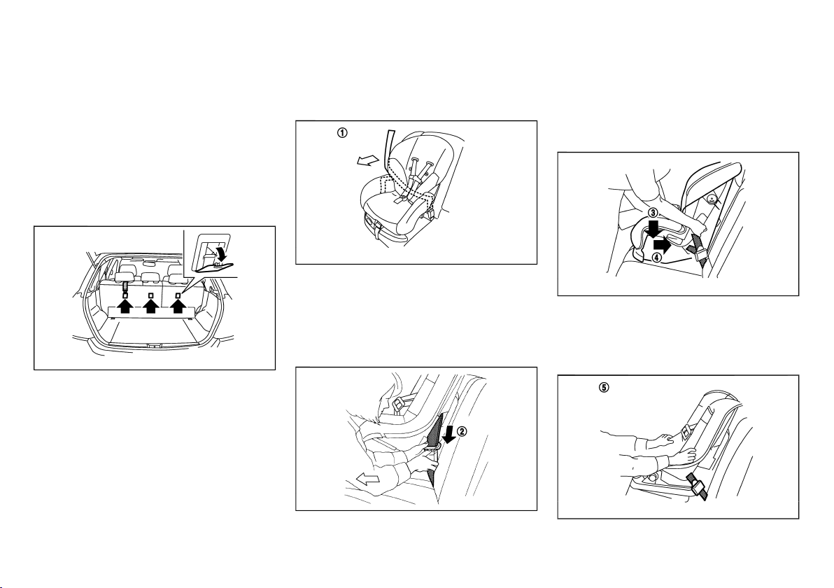
GUID-10B2BB22-866D-4899-AF59-A4697DD460CB
JVR0194X
The anchor points are located on the back side of the
rear seatbacks.
Step 1
Front-facing:
Be sure to follow the manufacturer’s instructions for
GUID-9E14C2E6-2E9C-4731-980B-C45B899B977B
SSS0758A
the proper use of your child restraint. Follow these
steps to install a front-facing child restraint on the rear
seats using 3-point type seat belt:
1. Position the child restraint on the seat
Step 2
1
.
*
SSS0493A
Safety — seats, seat belts and supplemental restraint system 1-13
Step 4
SSS0647A
4. Remove any additional slack from the seat belt;
press downward
3
and rearward
*
*
4
firmly in
the center of the child restraint with your knee to
compress the vehicle seat cushion and seatback
while pulling up on the seat belt.
Step 5
SSS0638A
Page 31

(32,1)
5. Test the child restraint before you place the child
6. Check to make sure that the child restraint is
Rear-facing:
5
in it
. Push the child restraint from side to side
*
and tug it forward to make sure that it is held
securely in place.
properly secured prior to each use. If the child
restraint is loose, repeat steps 3 through 5.
GUID-9E14C2E6-2E9C-4731-980B-C45B899B977B
2. Route the seat belt tongue through the child
restraint and insert it into the buckle
hear and feel the latch engage.
3. To prevent slack in the seat belt webbing, it is
necessary to secure the seat belt in place with
locking devices attached to the child restraint.
SSS0759A
1
.
*
4. Remove any additional slack from the seat belt;
press downward
the center of the child restraint with your hand to
compress the vehicle seat cushion and seatback
while pulling up on the seat belt.
Be sure to follow the manufacturer’s instructions for
Step 1
the proper use of your child restraint. Follow these
steps to install a rear-facing child restraint on the rear
seats using 3-point type seat belt:
1. Position the child restraint on the seat
1-14 Safety — seats, seat belts and supplemental restraint system
Step 2
Step 4
3
and rearward
*
SSS0654A
2
*
SSS0639A
4
*
until you
firmly in
5. Test the child restraint before you place the child
6. Check to make sure that the child restraint is
5
in it
. Push the child restraint from side to side
*
and tug it forward to make sure that it is held
securely in place.
properly secured prior to each use. If the child
restraint is loose, repeat steps 3 through 5.
Step 5
SSS0658A
Page 32

(33,1)
Installation on front passenger’s seat
GUID-4389C3B1-D7E8-41D1-8896-F4130AED3FD3
WARNING:
. Never install a rear-facing child restraint on
the front passenger’s seat when the front
passenger’s air bag is available. Supplemental front-impact air bags inflate with
great force. A rear-facing child restraint
could be struck by the supplemental frontimpact air bags in an accident and could
seriously injure or kill your child.
. Never install a child restraint with a top
tether strap on the front seat.
. NISSAN recommends that a child restraint
be installed on the rear seat. However, if you
must install a child restraint on the front
passenger’s seat, move the passenger’s seat
to the rearmost position.
. Child restraints for infants must be used in
the rear-facing direction and therefore must
not be used on the front passenger’s seat
when the front passenger’s air bag is available.
SSS0300A
Front-facing:
Be sure to follow the manufacturer’s instructions for
GUID-9E14C2E6-2E9C-4731-980B-C45B899B977B
the proper use of your child restraint. Follow these
steps to install a front-facing child restraint on the front
passenger’s seat using 3-point type seat belt:
1. Move the seat to the rearmost position
Steps 1 and 2
SSS0627
1
.
*
2. Adjust the head restraint to its highest position
2
.
*
3. Position the child restraint in the seat.
Safety — seats, seat belts and supplemental restraint system 1-15
Step 4
SSS0360C
4. Route the seat belt tongue through the child
restraint and insert it into the buckle
*
3
until you
hear and feel the latch engage.
5. To prevent slack in the seat belt webbing, it is
necessary to secure the seat belt in place with
locking devices attached to the child restraint.
Step 6
SSS0647B
6. Remove any additional slack from the seat belt;
press downward
4
and rearward
*
*
5
firmly in
the center of the child restraint with your knee to
compress the vehicle seat cushion and seatback
while pulling up on the seat belt.
Page 33

(34,1)
Step 7
SSS0302G
7. Test the child restraint before you place the child
6
in it
. Push the child restraint from side to side
*
and tug it forward to make sure that it is held
securely in place.
8. Check to make sure that the child restraint is
properly secured prior to each use. If the child
restraint is loose, repeat steps 4 through 7.
CHILD RESTRAINT INSTALLATION USING
2-POINT TYPE SEAT BELT (if equipped)
Installation on rear center seat
The direction of the child restraint system
depends on the type of the child restraint system
and the size of the child.
Front-facing:
If you must install a front-facing child restraint system
on the rear center seat, follow these steps:
1. Position the front-facing child restraint system on
the rear center seat.
Always follow the child restraint system manufacturer’s instructions for installation and use.
2. Route the seat belt tongue through the child
restraint system and insert it into the buckle until
you hear and feel the latch engage.
GUID-FA9A4201-4F83-4CEF-A803-A4EA00FB7110
GUID-DEE41DF7-B22C-4FBD-BC2B-BE887465FDCA
WARNING:
GUID-9E14C2E6-2E9C-4731-980B-C45B899B977B
SSS0512
SSS0513
3. To prevent slack in the lap belt, it is necessary to
secure the lap belt in place with a locking clip
A
*
Use the locking clip attached to the child restraint
system, or one which is equivalent in dimensions
and strength.
Be sure to follow the child restraint system
manufacturer’s instructions for belt routing.
4. Test the child restraint system before you place
the child in it. Tilt it from side to side. Try to tug it
forward and check if it is held securely in place.
5. Make sure that the child restraint system is
properly secured prior to each use.
.
1-16 Safety — seats, seat belts and supplemental restraint system
Page 34

(35,1)
Rear-facing:
GUID-9E14C2E6-2E9C-4731-980B-C45B899B977B
SSS0514
If you must install a rear-facing child restraint system
on the rear center seat, follow these steps:
1. Position the rear-facing child restraint system on
the rear center seat.
Always follow the child restraint system manufacturer’s instructions for installation and use.
2. Route the seat belt tongue through the child
restraint system and insert it into the buckle until
you hear and feel the latch engage.
Use the locking clip attached to the child restraint
system, or one which is equivalent in dimensions
and strength.
Be sure to follow the child restraint system
manufacturer’s instructions for belt routing.
4. Test the child restraint system before you place
the child in it. Tilt it from side to side. Try to tug it
forward and check if it is held securely in place.
5. Make sure that the child restraint system is
properly secured prior to each use.
SSS0513
3. To prevent slack in the lap belt, it is necessary to
secure the lap belt in place with a locking clip
A
*
.
Safety — seats, seat belts and supplemental restraint system 1-17
Page 35

(36,1)
SUPPLEMENTAL RESTRAINT
SYSTEM (SRS)
GUID-33C3B6B4-4C4F-4C02-B8D3-E13829BAF5BB
PRECAUTIONS ON SUPPLEMENTAL RESTRAINT SYSTEM (SRS)
This Supplemental Restraint System (SRS) section
contains important information concerning the driver’s
and passenger’s supplemental front-impact air bags,
supplemental side-impact air bags, supplemental
curtain side-impact air bags and pre-tensioner seat
belts.
Supplemental front-impact air bag system
This system can help cushion the impact force to the
head and chest area of the driver and/or front
passenger in certain frontal collisions. The supplemental front-impact air bag is designed to inflate on the
front where the vehicle is impacted.
GUID-17232207-DAB5-4C49-986F-9CACB2FAA6F8
GUID-5ED4D143-8D8A-4A77-BB38-6650BD18322C
Supplemental side-impact air bag system (if
equipped)
This system can help cushion the impact force to the
chest and pelvis areas of the driver and front
passenger in certain side-impact collisions. The
supplemental side-impact air bag is designed to inflate
on the side where the vehicle is impacted.
GUID-931BDBE2-9985-41F3-A607-F67C072B2A98
Supplemental curtain side-impact air bag
system (if equipped)
This system can help cushion the impact force to the
head of the driver and passengers in front and rear
outboard seating positions in certain side-impact
collisions. The supplemental curtain side-impact air
bag is designed to inflate on the side where the vehicle
is impacted.
The SRS is designed to supplement the accident
protection provided by the driver’s and passenger’s
seat belts and is not designed to substitute for them.
The SRS can help save lives and reduce serious
injuries. However, inflating air bags may cause abra-
1-18 Safety — seats, seat belts and supplemental restraint system
GUID-AA4E0875-0C69-409F-AE9A-D2E13197266A
sions or other injuries. Air bags do not provide
protection to the lower body. Seat belts should always
be correctly worn and the occupants should always be
seated a suitable distance away from the steering
wheel and instrument panel. (See “Seat belts” (P.1-7).)
The air bags inflate quickly in order to help protect the
occupants. The force of the air bags inflating can
increase the risk of injury if the occupants are too close
to, or are against, the air bag modules during inflation.
The air bags will deflate quickly after deployment.
The SRS operates only when the ignition switch
is in the “ON” position.
When the ignition switch is in the “ON” position,
the SRS air bag warning light illuminates for
about 7 seconds and then turns off. This
indicates that the SRS air bag system is operational. (See “SRS air bag warning light” (P.1-21).)
Page 36

(37,1)
SSS0131A
SSS0006
WARNING:
. The supplemental front-impact air bags
ordinarily will not inflate in the event of a
side impact, rear impact, rollover, or lower
severity frontal collision. Always wear the
seat belts to help reduce the risk or severity
of injury in accidents.
. The seat belts and the supplemental front-
impact air bags are most effective when you
are sitting well back and upright in the seat.
The front-impact air bags inflate with great
force. If you and your passengers are unrest-
SSS0132A
rained, leaning forward, sitting sideways, or
out of position in any way, you and your
passengers are at greater risk of injury or
death in an accident. You and your passengers may also receive serious or fatal
injuries from the supplemental front-impact
air bag if you are up against it when it
inflates. Always sit back against the seatback and as far away as practical from the
steering wheel or instrument panel. Always
use the seat belts.
Safety — seats, seat belts and supplemental restraint system 1-19
SSS0007
SSS0008
Page 37

(38,1)
SSS0009
WARNING:
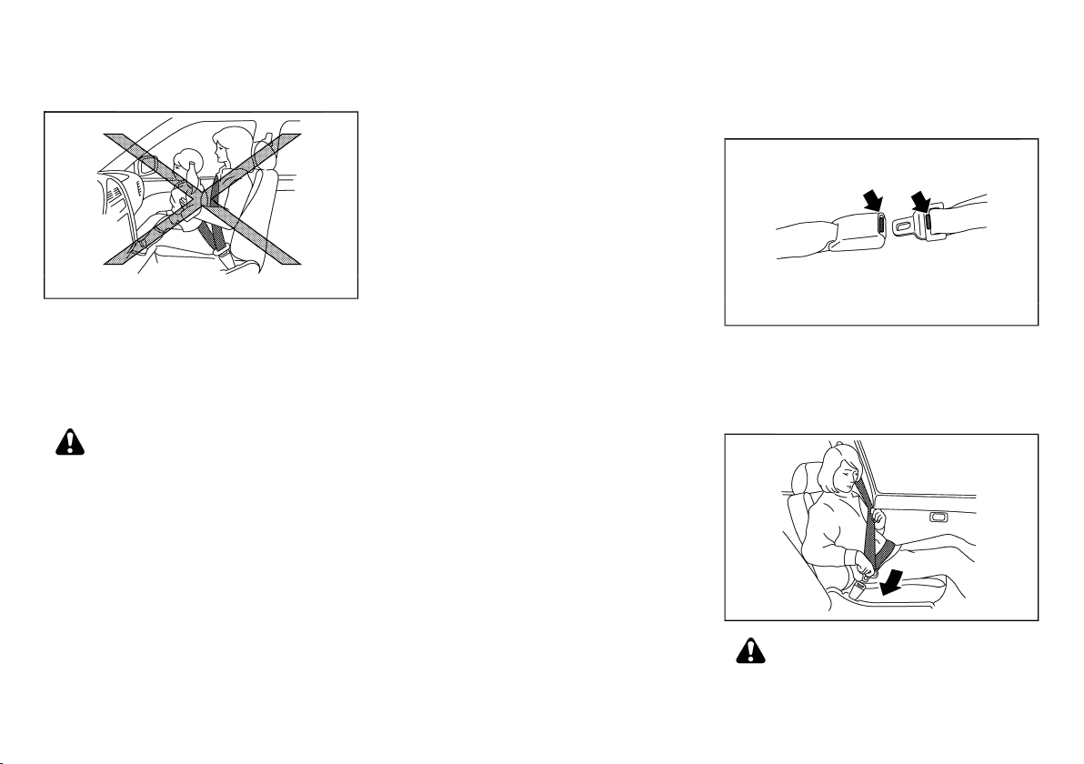
. Never let children ride unrestrained or
extend their hands or face out of the
window. Do not attempt to hold them in
your lap or arms. Some examples of dangerous riding positions are shown in the
illustrations.
. Children may be severely injured or killed if
they are not properly restrained when the air
bags inflate.
. Never install a rear-facing child restraint
system on the front seat. An inflating
supplemental front-impact air bag could
seriously injure or kill your child. (See “Child
restraints” (P.1-12).)
SSS0140
SSS0099
SSS0100
1-20 Safety — seats, seat belts and supplemental restraint system
SSS0159
SSS0059A
SSS0162
Page 38

(39,1)
WARNING:
. The supplemental side-impact air bags and
supplemental curtain side-impact air bags
ordinarily will not inflate in the event of a
front impact, rear impact, rollover, or lower
severity side collision. Always wear the seat
belts to help reduce the risk or severity of
injury in accidents.
. The seat belts and the supplemental side-
impact air bags and supplemental curtain
side-impact air bags are most effective when
you are sitting well back and upright in the
seat. The supplemental side-impact air bags
and supplemental curtain side-impact air
bags inflate with great force. If you and your
passengers are unrestrained, leaning forward, sitting sideways, or out of position in
any way, you and your passengers are at
greater risk of injury or death in an accident.
. Do not allow anyone to place their hands,
legs, or face near the supplemental sideimpact air bags and supplemental curtain
side-impact air bags on the sides of the
seatback of the front seats or near the side
roof rails. Do not allow anyone sitting in the
front seats or rear outboard seats to extend
their hands out of the windows or lean
against the doors. Some examples of dangerous riding positions are shown in the
illustrations.
. When sitting in the rear seats, do not hold
onto the seatback of the front seats. If the
supplemental side-impact air bags and supplemental curtain side-impact air bags inflate, you may be seriously injured. Be
especially careful with children, who should
always be properly restrained.
. Do not use seat covers on the front seat-
backs. They may interfere with the supplemental side-impact air bag inflations.
Pre-tensioner seat belt system (if equipped)
The pre-tensioner system may activate with the
GUID-DA98CD59-33B1-4E88-A881-D47884262132
supplemental air bag system in certain types of
collisions. Working with the seat belt retractor and
anchor, it helps tighten the seat belt the instant the
vehicle becomes involved in certain types of collisions,
helping to restrain front seat occupants. (See “Pretensioner seat belt system” (P.1-26).)
Air bag warning label
GUID-4E4CA60F-08F0-4F36-959A-A1C0F36A8F77
SSS0603
Warning labels about the supplemental air bag system
are placed in the vehicle as shown in the illustration.
SRS air bag:
The warning label
GUID-9E14C2E6-2E9C-4731-980B-C45B899B977B
1
is located on the surface of the
*
driver’s and/or passenger’s sun visor.
SRS front-impact passenger air bag :
The warning label
GUID-9E14C2E6-2E9C-4731-980B-C45B899B977B
2
(if equipped) is located on the
*
side of the passenger’s side instrument panel.
This label warns you not to fit a rear-facing child
restraint system on the front passenger seat as such a
restraint system used in this position could cause
serious injury to the infant in case of air bag
deployment during a collision.
In vehicles equipped with a front-impact passenger air
bag system, use a rear-facing child restraint system
only on the rear seats. “Extreme Hazard! Do not use a
rearward facing child restraint on a seat protected by
an airbag in front of it!"
When installing a child restraint system in your vehicle,
always follow the child restraint system manufacturer’s
instructions for installation.
For additional information, see “Child restraints” (P.1-
12).
SRS air bag warning light
GUID-E1046484-BC1B-4375-8935-AFDC18A208A0
SPA1097
The SRS air bag warning light, displaying in the
instrument panel, monitors the circuits for the air bag
systems, pre-tensioners and all related wiring.
When the ignition switch is in the “ON”, the SRS air
Safety — seats, seat belts and supplemental restraint system 1-21
Page 39

(40,1)
bag warning light illuminates for about 7 seconds and
then turns off. This indicates that the SRS air bag
systems are operational.
If any of the following conditions occur, the air bags
and/or pre-tensioner seat belt systems need servicing:
. The SRS air bag warning light remains on after
approximately 7 seconds.
. The SRS air bag warning light flashes intermit-
tently.
. The SRS air bag warning light does not illuminate
at all.
Under these conditions, the air bags and/or pretensioner seat belt systems may not operate properly.
They must be checked and repaired. Contact a
NISSAN dealer immediately.
SUPPLEMENTAL AIR BAG SYSTEMS
1. Crash zone sensor
2. Supplemental front-impact air bag modules
3. Supplemental side-impact air bag modules (if
equipped)
4. Supplemental curtain side-impact air bag inflators (if equipped)
5. Supplemental curtain side-impact air bags (if
equipped)
GUID-91381D58-02AD-4301-98FF-DA7420D15AD9
SSS1170
6. Lap outer pre-tensioners (driver’s side) (if
equipped)
7. Pre-tensioner seat belt retractors (if equipped)
8. Satellite sensors (if equipped)
9. Supplemental air bag diagnosis sensor unit
1-22 Safety — seats, seat belts and supplemental restraint system
Page 40

(41,1)
WARNING:
. Do not place any objects on the steering
wheel pad, on the instrument panel, and
near the front door finishers and the front
seats. Do not place any objects between any
occupants and the steering wheel pad, on
the instrument panel, and near the front
door finishers and the front seats. Such
objects may become dangerous projectiles
and cause injury if a supplemental air bag
inflates.
. Immediately after inflation, several supple-
mental air bag system components will be
hot. Do not touch them: you may severely
burn yourself.
. No unauthorized changes should be made
to any components or wiring of the supplemental air bag systems. This is to prevent
accidental inflation of the supplemental air
bags or damage to the supplemental air bag
systems.
. Do not make unauthorized changes to your
vehicle’s electrical system, suspension system, front end structure, and side panels.
This could affect proper operation of the
supplemental air bag systems.
. Tampering with the supplemental air bag
systems may result in serious personal
injury. Tampering includes changes to the
steering wheel and the instrument panel by
placing materials over the steering wheel
pad and above, around or on the instrument
panel or by installing additional trim materials around the supplemental air bag systems.
. Work around and on the supplemental air
bag systems should be done by a NISSAN
dealer. The SRS wiring should not be
modified or disconnected. Unauthorized
electrical test equipment and probing devices should not be used on the supplemental air bag systems.
. The SRS wiring harness connectors are
yellow and/or orange for easy identification.
When the air bags inflate, a fairly loud noise may be
heard, followed by the release of smoke. This smoke is
not harmful and does not indicate a fire. Care should
be taken not to inhale it, as it may cause irritation and
choking. Those with a history of a breathing condition
should get fresh air promptly.
Supplemental front-impact air bag system
The driver’s supplemental front-impact air bag is
located at the center of the steering wheel. The
passenger’s supplemental front-impact air bag is
located at the instrument panel above the glove box.
The supplemental front-impact air bag system is
designed to inflate in higher severity frontal collisions,
although it may inflate if the forces in another type of
collision are similar to those of a higher severity frontal
impact. It may not inflate in certain frontal collisions.
Vehicle damage (or lack of it) is not always an
indication of proper supplemental front-impact air
bag system operation.
GUID-9460E8D6-2EA9-49DC-B8FB-A6C61A3E2E24
Safety — seats, seat belts and supplemental restraint system 1-23
Supplemental side-impact air bag system (if
equipped)
The supplemental side-impact air bag is located at the
outside of the front seats’ seatbacks.
The supplemental side-impact air bag system is
designed to inflate in higher severity side collisions,
although it may inflate if the forces in another type of
collision are similar to those of a higher severity side
impact. It may not inflate in certain side collisions.
Vehicle damage (or lack of it) is not always an
indication of proper supplemental side-impact air bag
system operation.
GUID-AD090687-948D-4A34-990A-4EDF7903C334
SSS0978
Supplemental curtain side-impact air bag
system (if equipped)
The supplemental curtain side-impact air bag is
located at the roof rails.
The supplemental curtain side-impact air bag system is
designed to inflate in higher severity side collisions,
although it may inflate if the forces in another type of
collision are similar to those of a higher severity side
impact. It may not inflate in certain side collisions.
Vehicle damage (or lack of it) is not always an
indication of proper supplemental curtain side-impact
air bag system operation.
GUID-1393FD29-021C-41AD-B70E-7CEF3645FC20
Page 41

(42,1)
SRS AIR BAG DEPLOYMENT CONDITIONS
The SRS air bags activate in the event of a front or side
GUID-B03AB201-D2AB-4DAE-8FAB-EB80C9664042
impact in which the vehicle occupants may be severely
injured even if they are wearing the seat belts properly.
They may not activate when the crash energy is
absorbed and/or distributed by the vehicle body.
Vehicle damage (or lack of it) is not always an
indication of proper SRS air bag system operation.
When the SRS air bag will deploy
Supplemental front-impact air bags:
The supplemental front-impact air bag system is
GUID-4E3C0A07-333F-4CCE-B81E-6B0A36C9E2A6
GUID-9E14C2E6-2E9C-4731-980B-C45B899B977B
designed to inflate in higher severity frontal collisions.
Some examples are shown in the following illustrations.
Supplemental side-impact and curtain side-impact air bags (if equipped):
The supplemental side-impact and curtain side-impact
GUID-9E14C2E6-2E9C-4731-980B-C45B899B977B
air bag systems are designed to inflate in higher
severity side collisions. Some examples are shown in
the following illustrations.
JVR0151X
The supplemental front-impact air bag system will
deploy in the event of an impact which exceeds a 25
. Hitting a curb, pavement edge or hard surface at
high speed
. Falling into a deep hole or ditch
. Landing hard on the ground after jumping
km/h frontal collision with a solid wall that does not
move or deform.
The supplemental front-impact air bag system may also
deploy when the vehicle receives severe damage to
the undercarriage.
1-24 Safety — seats, seat belts and supplemental restraint system
(supplemental side-impact air bag system)
JVR0161X
JVR0152X
JVR0162X
(supplemental curtain side-impact air bag system)
. The supplemental side-impact and curtain side-
impact air bags will deploy in the event of a side
impact with a normal passenger vehicle that
exceeds at a speed of 25 km/h.
Page 42

(43,1)
When the SRS air bag is unlikely to deploy
The SRS air bags may not deploy in cases where the
GUID-A244E3F1-47EE-4847-A4AE-551410672172
impact is not forceful enough to inflate the SRS air
bags.
For example, if the vehicle strikes an object, such as a
parked vehicle or sign pole, which can move or deform
on impact, the SRS air bags are unlikely to deploy.
Supplemental front-impact air bags:
GUID-9E14C2E6-2E9C-4731-980B-C45B899B977B
JVR0154X
. Striking a vehicle of the same class that is parked
. Crashing into a solid utility pole
JVR0155X
. Running under the tail gate of a truck
. A frontal offset impact to the guard rails
Supplemental side-impact and curtain side-impact air bags (if equipped):
GUID-9E14C2E6-2E9C-4731-980B-C45B899B977B
JVR0156X
. A collision from the side at an angle
. A side impact with a two-wheeled vehicle
JVR0157X
. A collision from the side impacting the vehicle
engine room (luggage room)
. Vehicle rollover
JVR0163X
. A frontal offset impact to the guard rails
. A collision with a pole
When the SRS air bag will not deploy
Once the SRS air bag has inflated, the air bag module
GUID-06B53184-8FC9-4081-8498-763EDF159820
will not function again if your vehicle collides with
another vehicle or an object.
Other examples where the SRS air bag will not deploy
are shown in the following illustrations.
Supplemental front-impact air bags:
GUID-9E14C2E6-2E9C-4731-980B-C45B899B977B
JVR0159X
. A collision from the side or rear
Safety — seats, seat belts and supplemental restraint system 1-25
Page 43

(44,1)
. Vehicle rollover
Supplemental side-impact and curtain side-impact air bags (if equipped):
. A frontal collision with a parked or moving vehicle
. A rear collision
GUID-9E14C2E6-2E9C-4731-980B-C45B899B977B
JVR0160X
PRE-TENSIONER SEAT BELT SYSTEM (if
equipped)
. The pre-tensioner seat belt cannot be re-
used after activation. It must be replaced
together with the retractor and buckle as a
unit.
. If the vehicle becomes involved in a collision
but the pre-tensioner is not activated, be
sure to have the pre-tensioner system
checked and, if necessary, replaced by a
NISSAN dealer.
. No unauthorized changes should be made
to any components or wiring of the pretensioner seat belt system. This is to prevent
accidental activation of the pre-tensioner
seat belt or damage to the pre-tensioner
GUID-DB266FAA-0FF0-4D08-8D8B-A4F08BB31581
WARNING:
seat belt system.
. Work around or on the pre-tensioner seat
belt system should be done by a NISSAN
dealer. The SRS wiring should not be
modified or disconnected. Unauthorized
electrical test equipment and probing devices should not be used on the pretensioner seat belt system.
. If you need to dispose of the pre-tensioner
seat belt system, or scrap the vehicle,
contact a NISSAN dealer. Correct pre-tensioner disposal procedures are set forth in
the appropriate NISSAN Service Manual.
Incorrect disposal procedures could cause
personal injury.
The pre-tensioner system may activate with the
supplemental air bag system in certain types of
collisions. Working with the seat belt retractor, it helps
tighten the seat belt when the vehicle becomes
involved in certain types of collisions, helping to
restrain front seat occupants.
The pre-tensioner is encased with the front seat belt’s
retractor and anchor. These seat belts are used the
same as conventional seat belts.
When the pre-tensioner seat belt activates, a fairly loud
noise may be heard, followed by the release of smoke.
This smoke is not harmful and does not indicate a fire.
Care should be taken not to inhale it, as it may cause
irritation and choking. Those with a history of a
breathing condition should get fresh air promptly.
REPAIR AND REPLACEMENT PROCEDURE
. Once the air bags have been inflated, the air
bag modules will not function and must be
replaced. The air bag modules must be
replaced by a NISSAN dealer. The inflated
air bag modules cannot be repaired.
. The air bag systems should be inspected by
a NISSAN dealer if there is any damage to
the front end portion of the vehicle.
. If you need to dispose of the SRS or scrap
the vehicle, contact a NISSAN dealer. Correct disposal procedures are set forth in the
appropriate NISSAN Service Manual. Incorrect disposal procedures could cause personal injury.
The air bags and pre-tensioner seat belts are designed
to activate on a one-time-only basis. As a reminder,
unless the SRS air bag warning light is damaged, the
SRS air bag warning light remains illuminated after
inflation has occurred. The repair and replacement of
the SRS should be done only by a NISSAN dealer.
When maintenance work is required on the vehicle,
information about the air bags, pre-tensioner seat belts
and related parts should be pointed out to the person
performing the maintenance. The ignition switch
should always be in the “LOCK” position when working
under the hood or inside the vehicle.
GUID-D0639600-4BF7-43B2-8895-BCE9B314674E
WARNING:
1-26 Safety — seats, seat belts and supplemental restraint system
Page 44

(45,1)
2 Instruments and controls
Cockpit ........................................................................................................... 2-2
Left-Hand Drive (LHD) models ......................................................... 2-2
Right-Hand Drive (RHD) models ...................................................... 2-3
Instrument panel .......................................................................................... 2-4
Left-Hand Drive (LHD) models ......................................................... 2-4
Right-Hand Drive (RHD) models ...................................................... 2-5
Meters and gauges ..................................................................................... 2-6
Speedometer .......................................................................................... 2-6
Tachometer ............................................................................................. 2-6
Engine coolant temperature gauge .................................................. 2-7
Fuel gauge .............................................................................................. 2-7
Instrument brightness control ............................................................ 2-7
Vehicle information display ................................................................. 2-8
Odometer ............................................................................................. 2-10
Warning/indicator lights and audible reminders ............................... 2-11
Checking bulbs .................................................................................. 2-12
Warning lights ..................................................................................... 2-12
Indicator lights .................................................................................... 2-14
Audible reminders .............................................................................. 2-16
Headlight and turn signal switch .......................................................... 2-17
Xenon headlights (if equipped) ...................................................... 2-17
Headlight switch ................................................................................ 2-17
Headlight aiming control (if equipped) ......................................... 2-18
Turn signal switch .............................................................................. 2-19
Fog light switch (if equipped) ............................................................... 2-19
Front fog lights ................................................................................... 2-19
Wiper and washer switch ...................................................................... 2-20
Windshield wiper and washer switch ........................................... 2-20
Rear window wiper and washer switch ....................................... 2-21
Defogger switch ....................................................................................... 2-21
Horn ............................................................................................................ 2-22
Windows .................................................................................................... 2-22
Power windows ................................................................................ 2-22
Sunroof (if equipped) ............................................................................. 2-24
Automatic sunroof ........................................................................... 2-24
Power outlet (if equipped) .................................................................... 2-25
Ashtray and cigarette lighter (if equipped) ....................................... 2-25
Front .................................................................................................... 2-25
Rear ..................................................................................................... 2-26
Storages ..................................................................................................... 2-26
Glove box .......................................................................................... 2-26
Console box ...................................................................................... 2-26
Cup holders ...................................................................................... 2-27
Sunglasses holder ........................................................................... 2-27
Coat hook (if equipped) ................................................................ 2-28
Card holders (if equipped) ........................................................... 2-28
Cargo cover ...................................................................................... 2-28
Luggage hooks (if equipped) ....................................................... 2-29
Sun visors .................................................................................................. 2-29
Interior lights ............................................................................................. 2-29
Room light ......................................................................................... 2-29
Map lights .......................................................................................... 2-30
Vanity mirror lights (if equipped) ................................................. 2-30
Cargo room light .............................................................................. 2-30
>
Page 45

(46,1)
COCKPIT
GUID-A889F682-B2FA-4219-BAA7-21E60B066461
LEFT-HAND DRIVE (LHD) MODELS
GUID-C64B5478-FBE5-4DDB-B516-11C1A755DFE5
1. Instrument brightness control switch
2. Outside rearview mirror control switch
3. Headlight, fog light* and turn signal switch
— Headlight
— Turn signal
— Fog light*
4. Steering wheel
— Electric power steering system
— Horn
— Driver’s supplemental front-impact air bag
5. Wiper and washer switch
6. Shift lever
— Continuously Variable Transmission (CVT)
— Manual Transmission (MT)
7. Fuse box cover
JVC0480X
8. Vehicle Dynamic Control (VDC) OFF switch*
9. Tilting/telescopic steering wheel lever
10. Steering-wheel-mounted controls (left side)
switch (odometer and trip computer)
—
— Audio system*
— Bluetooth
out navigation system)*
— Bluetooth
®
Hands-Free Phone System (with-
®
Hands-Free Phone System (with
navigation system)**
11. Steering-wheel-mounted controls (right side)
— Cruise control switches*
*: if equipped
**: Refer to the separate NISSAN Connect Owner’s
Manual (if equipped).
2-2 Instruments and controls
Page 46

(47,1)
RIGHT-HAND DRIVE (RHD) MODELS
GUID-702BCE5D-30D3-45D9-93B3-B10AB645D1F4
1. Shift lever
— Continuously Variable Transmission (CVT)
— Manual Transmission (MT)
2. Wiper and washer switch
3. Steering wheel
— Electric power steering system
— Horn
— Driver’s supplemental front-impact air bag
JVC0437X
4. Headlight, fog light and turn signal switch
— Headlight
— Turn signal
— Fog light*
5. Steering-wheel-mounted controls (left side)
—
switch (odometer and trip computer)
— Audio system*
— Bluetooth
®
Hands-Free Phone System (with-
out navigation system)*
®
— Bluetooth
Hands-Free Phone System (with
navigation system)**
6. Steering-wheel-mounted controls (right side)
— Cruise control switches*
7. Tilting/telescopic steering wheel lever
8. Outside rearview mirror control switch
9. Vehicle Dynamic Control (VDC) OFF switch*
10. Headlight aiming control switch*
11. Instrument brightness control switch
12. Fuse box cover
*: if equipped
**: Refer to the separate NISSAN Connect Owner’s
Manual (if equipped).
Instruments and controls 2-3
Page 47

(48,1)
INSTRUMENT PANEL
GUID-4C19A22A-88D2-42B4-B1FC-1E8BEB670008
LEFT-HAND DRIVE (LHD) MODELS
1. Meters and gauges
2. Push-button ignition switch (models with Intelligent Key system)
3. Center ventilator
4. Hazard indicator flasher switch
5. Audio system* or Navigation system**
6. Passenger’s front-impact air bag
7. Side ventilator
GUID-2B396544-2625-4DCC-9B66-D7D429748127
15. Glove box
*: if equipped
**: Refer to the separate NISSAN Connect Owner’s
Manual (if equipped).
JVC0307X
8. Fuel filler lid release handle
9. Hood release handle
10. Ignition switch (models without Intelligent Key
system)
11. Defogger switch
12. Ashtray and cigarette lighter
13. Parking brake
14. Heater and air conditioner control
2-4 Instruments and controls
Page 48

(49,1)
RIGHT-HAND DRIVE (RHD) MODELS
GUID-AD5F3C0E-3052-40A3-AEE9-51A230C7AB38
1. Side ventilator
2. Passenger’s front-impact air bag
3. Audio system* or Navigation system**
4. Hazard indicator flasher switch
5. Center ventilator
6. Push-button ignition switch (models with Intelligent Key system)
7. Meters and gauges
15. Fuel filler lid release handle
*: if equipped
**: Refer to the separate NISSAN Connect Owner’s
Manual (if equipped).
JVC0306X
8. Glove box
9. Heater and air conditioner control
10. Parking brake
11. Power outlet* or Ashtray and cigarette lighter*
12. Defogger switch
13. Ignition switch (models without Intelligent Key
system)
14. Hood release handle
Instruments and controls 2-5
Page 49

(50,1)
METERS AND GAUGES
GUID-B1AEB184-BF62-47CF-A091-1C760F46DBDC
1. Tachometer
2. Vehicle information display
— Odometer/twin trip odometer
— Outside air temperature
— Continuously Variable Transmission (CVT)
position indicator*
— Trip computer
3. Engine coolant temperature gauge
4. Fuel gauge
JVI0275X
5. Speedometer
6. Warning/indicator lights
*: if equipped
The needle indicators may move slightly after
the ignition switch is placed in the “OFF” or
“LOCK” position. This is not a malfunction.
SPEEDOMETER
GUID-4057A8FE-5D9D-4339-9CE1-83752D2DF168
JVI0276X
The speedometer indicates the vehicle speed.
TACHOMETER
GUID-91A61FD5-DD5D-4219-8890-60FFEBD2E80E
JVI0278X
The tachometer indicates the engine speed in revolutions per minute (rpm). Do not rev the engine into
the red zone
A
.
*
2-6 Instruments and controls
Page 50

(51,1)
ENGINE COOLANT TEMPERATURE
GAUGE
The engine coolant temperature gauge indicates the
engine coolant temperature.
The engine coolant temperature is normal when the
gauge needle points within the zone
illustration.
The engine coolant temperature will vary with the
outside air temperature and driving conditions.
GUID-C52CA372-EAD4-42AF-BEA6-2FBA08B46DF4
1
shown in the
*
JVI0279X
JVI0629X
Type A
Type B
CAUTION:
. If the gauge indicates engine coolant tem-
perature near the hot (H) end of the normal
range, reduce vehicle speed to decrease
temperature.
. If the gauge is over the normal range, stop
the vehicle as soon as safely possible.
. If the engine is overheated, continued op-
eration of the vehicle may seriously damage
the engine. (See “If your vehicle overheats”
(P.6-7) for immediate action required.)
FUEL GAUGE
GUID-1C712BA5-30E9-4629-B9C3-BDF27E432243
JVI0280X
The fuel gauge indicates the approximate fuel level in
the tank when the ignition switch is in the “ON”
position.
The gauge may move slightly during braking, turning,
accelerating, or going up and down hills due to
movement of fuel in the tank.
The low fuel warning light
illuminates when the
fuel level in the tank is getting low. Refuel as soon as it
is convenient, preferably before the gauge reads 0.
The arrow,
, indicates that the fuel filler lid is
located on the right side of the vehicle.
CAUTION:
Refuel before the gauge reads 0 (empty) .
There is a small reserve of fuel in the tank when the fuel
gauge reads 0 (empty).
INSTRUMENT BRIGHTNESS CONTROL
GUID-5A2F864F-23EF-4936-8ECF-B52B0FC47BEE
JVI0458X
The instrument brightness control operates when the
ignition switch is in the “ON” position.
Push the + side of the switch to increase the
brightness of the meter panel. Push the - side of the
switch to decrease the brightness of the meter panel.
When the brightness level reaches the maximum or
minimum, a beep will sound.
Instruments and controls 2-7
Page 51

(52,1)
VEHICLE INFORMATION DISPLAY
GUID-6A96731E-D986-440A-8965-55360376E679
Continuously Variable Transmission (CVT)
position indicator (if equipped)
The Continuously Variable Transmission (CVT) position
indicator indicates the shift lever position when the
ignition switch is in the “ON” position.
Trip computer
GUID-894B5E32-A4FA-434E-BE33-534A2D513E38
GUID-39FE4747-56C6-46C6-9B77-8C5909D9671B
Eco Pedal guide (if equipped):
GUID-9E14C2E6-2E9C-4731-980B-C45B899B977B
JVI0444X
When the ignition switch is placed in the “ON”
position, the vehicle information display shows the
following information:
1
Trip computer
*
—“Trip computer” (P.2-8)
2
Outside air temperature
*
—“Outside air temperature” (P.2-8)
3
Odometer/Twin trip odometer
*
—“Odometer/Twin trip odometer” (P.2-10)
4
Continuously Variable Transmission (CVT) position
*
indicator (if equipped)
—“Continuously Variable Transmission (CVT)
position indicator” (P.2-8)
Outside air temperature
The outside air temperature is displayed in 8C.
When the outside air temperature becomes 38C
(378F) or lower, the outside air temperature display
blinks to give a warning.
The display will stop blinking after 1 minute or when
the outside air temperature becomes 48C (398F) or
above.
2-8 Instruments and controls
GUID-57A3E97D-A12E-45FF-AB08-41D3461609AB
JVI0452X
The switch for the trip computer is located on the left
side of the steering wheel.
When the ignition switch is placed in the “ON”
position, modes of the trip computer can be selected
by pushing the
Each time the
will change as follows:
Eco Pedal guide (if equipped) ? Average fuel
consumption (graph and digit) ? Average fuel
consumption (digit) ? Average vehicle speed ?
Distance to empty (dte) ? (TRIP A ? TRIP B) ?
Eco Pedal guide (if equipped)
switch
switch
A
.
*
A
is pushed, the display
*
Type A
Type B
Use the Eco Pedal guide
economy.
When the Eco Pedal guide bar is in the green range, it
indicates that the vehicle is driven within range of
economy drive.
If the Eco Pedal guide bar is out of green range, it
indicates that the accelerator pedal is depressed over
the range of economy drive.
The Eco Pedal guide bar is not displayed when the
cruise control system (if equipped) is operating.
1
for improving fuel
*
JVI0575X
JVI0454X
Page 52

(53,1)
Average fuel consumption (km/l or l/100km):
GUID-9E14C2E6-2E9C-4731-980B-C45B899B977B
JVI0576X
Type A
Average vehicle speed (km/h):
The average vehicle speed mode shows the average
vehicle speed
done by pushing the
second. The display is updated every 30 seconds. The
first 30 seconds after a reset, the display shows “——”.
Distance to empty (dte — km):
GUID-9E14C2E6-2E9C-4731-980B-C45B899B977B
JVI0505X
1
since the last reset. Resetting is
*
GUID-9E14C2E6-2E9C-4731-980B-C45B899B977B
switch
A
for longer than 1
*
The dte mode includes a low range warning feature:
when the fuel level is low, the dte mode is automatically
selected and the digits blink in order to draw the
driver’s attention. Push the
to the mode that was selected before the warning
occurred.
When the fuel level drops even lower, the dte display
will change to “----”.
. If the amount of fuel added is small, the
display just before the ignition switch is
turned off may continue to be displayed.
. When driving uphill or rounding curves, the
fuel in the tank shifts, which may momentarily change the display.
Resetting displays:
Push the switch
The display of average fuel consumption, average
vehicle speed and trip odometer (TRIP B only) will be
reset at the same time.
GUID-9E14C2E6-2E9C-4731-980B-C45B899B977B
A
for longer than 3 seconds.
*
switch
A
*
to return
A
*
JVI0456X
1
*
for longer
The average fuel consumption mode provides the
current and average fuel consumption graphically
The location
The average fuel consumption mode shows the
average fuel consumption since the last reset. Resetting is done by pushing the
than 1 second.
The display is updated every 30 seconds. At about the
first 500 m (1/3 miles) after a reset, the display shows
“---” and the digit
2
*
Type B
also shows the average consumption.
switch
2
is not displayed.
*
.
The distance to empty (dte) mode provides you with an
estimation of the distance
before refueling. The dte is constantly being calculated, based on the amount of fuel in the fuel tank and
the actual fuel consumption.
The display is updated every 30 seconds.
1
that can be driven
*
JVI0455X
Instruments and controls 2-9
Page 53

(54,1)
ODOMETER
Odometer/Twin trip odometer
The odometer/twin trip odometer is displayed on the
vehicle information display when the ignition switch is
in the “ON” position.
The odometer
vehicle has been driven.
The twin trip odometer
individual trips.
GUID-06C6E42D-73F4-482B-BB3A-4937859BAF18
GUID-6EED0165-7023-4303-8B0A-F985CECD83EB
JVI0451X
JVI0452X
1
displays the total distance the
*
2
displays the distance of
*
Changing trip odometer display:
Push the switch
wheel to change the display as follows:
TRIP A ? TRIP B ? Trip computer mode ? TRIP A
For trip computer information, see “Trip computer”
(P.2-8).
Resetting trip odometer:
Push the switch
to reset the trip odometer to zero.
GUID-9E14C2E6-2E9C-4731-980B-C45B899B977B
A
on the left side of steering
*
GUID-9E14C2E6-2E9C-4731-980B-C45B899B977B
A
for approximately 1 second
*
2-10 Instruments and controls
Page 54

(55,1)
WARNING/INDICATOR LIGHTS AND
AUDIBLE REMINDERS
GUID-01AE4331-D28E-4FB3-8861-DB744FC3C608
Anti-lock Braking System (ABS) warning
light*
Brake warning light Seat belt warning light Security indicator light*
Charge warning light Speed [120 km/h (75 MPH)] warning light* Small light indicator light
Door open warning light
Electric power steering warning light
Engine oil pressure warning light Cruise indicator light* Turn signals/hazard indicator lights
Intelligent Key system warning light* Engine start operation indicator light*
Low fuel warning light Front fog lights indicator light* *: if equipped
Low washer fluid warning light* High beam indicator light
P position selecting warning light* Malfunction Indicator Light (MIL)
Supplemental Restraint System (SRS) air
bag warning light
Vehicle Dynamic Control (VDC) warning
light*
Sport mode indicator light*
Trailer direction indicator light*
Vehicle Dynamic Control (VDC) off indicator
light*
Instruments and controls 2-11
Page 55

(56,1)
CHECKING BULBS
With all doors closed, apply the parking brake, fasten
GUID-BDC7AA48-32E8-4155-91D7-78D21C20167B
the seat belts and place the ignition switch in the “ON”
position without starting the engine. If equipped, the
following lights will illuminate:
, , ,
.
If equipped, the following lights will illuminate briefly
and then turn off:
, , , , , ,
.
If any lights fail to illuminate, it may indicate a burnedout bulb or an open circuit in the electrical system.
Have the system checked, and if necessary repaired,
by a NISSAN dealer promptly.
WARNING LIGHTS
GUID-828072D2-26BC-4788-ACD5-53E300A07CD5
Anti-lock Braking System (ABS)
warning light (if equipped)
When the ignition switch is in the “ON” position, the
Anti-lock Braking System (ABS) warning light illuminates and then turns off. This indicates the ABS is
operational.
If the ABS warning light illuminates while the engine is
running, or while driving, it may indicate the ABS is not
functioning properly. Have the system checked by a
NISSAN dealer promptly.
If an ABS malfunction occurs, the anti-lock function is
turned off. The brake system then operates normally,
but without anti-lock assistance. (See “Brake system”
(P.5-22).)
GUID-E5BB8BF0-4438-4F1D-9AAB-502959EB89E9
Brake warning light
GUID-4B36ABF6-BAC4-4E80-8EC1-73BF6F892FA9
WARNING:
. If the brake fluid level is below the minimum
mark on the brake fluid reservoir, do not
drive the vehicle until the brake system has
been checked by a NISSAN dealer.
. Even if you judge it to be safe, have your
vehicle towed because driving it could be
dangerous.
. Depressing the brake pedal without the
engine running and/or with a low brake
fluid level could increase the stopping distance and require greater pedal travel distance and effort.
The brake warning light indicates the parking brake
system operation, a low brake fluid level of the brake
system and an Anti-lock Braking System (ABS)
malfunction.
Parking brake warning indicator:
When the ignition switch is placed in the “ON”
GUID-9E14C2E6-2E9C-4731-980B-C45B899B977B
position, the brake warning light illuminates. When
the engine is started and the parking brake is released,
the brake warning light turns off.
If the parking brake is not fully released, the brake
warning light remains on. Be sure that the brake
warning light has turned off before driving. (See
“Parking brake” (P.3-19).)
Low brake fluid warning indicator:
If the brake warning light illuminates while the engine is
GUID-9E14C2E6-2E9C-4731-980B-C45B899B977B
running, or while driving, and the parking brake is
released, it may indicate the brake fluid level is low.
When the brake warning light illuminates while driving,
stop the vehicle safely as soon as possible. Stop the
engine and check the brake fluid level. If the brake fluid
level is at the minimum mark, add brake fluid as
necessary. (See “Brake fluid” (P.8-13).)
If the brake fluid level is sufficient, have the brake
system checked by a NISSAN dealer promptly.
Anti-lock Braking System (ABS) warning indicator (if equipped):
When the parking brake is released and the brake fluid
GUID-9E14C2E6-2E9C-4731-980B-C45B899B977B
level is sufficient, if both the brake warning light and the
Anti-lock Braking System (ABS) warning light illuminate, it may indicate the ABS is not functioning
properly. Have the brake system checked, and if
necessary repaired, by a NISSAN dealer promptly.
(See “Anti-lock Braking System (ABS) warning light”
(P.2-12).)
Charge warning light
When the ignition switch is in the “ON” position, the
GUID-19785261-65C1-4F82-BDA4-38E8C7729252
charge warning light illuminates. After starting the
engine, the charge warning light turns off. This
indicates the charging system is operational.
If the charge warning light illuminates while the engine
is running, or while driving, it may indicate the charging
system is not functioning properly and may need
servicing.
When the charge warning light illuminates while
driving, stop the vehicle safely as soon as possible.
Stop the engine and check the alternator belt. If the
alternator belt is loose, broken or missing, the charging
system needs repair. (See “Drive belt” (P.8-11).)
If the alternator belt appears to be functioning correctly
but the charge warning light remains illuminated, have
the charging system checked by a NISSAN dealer
promptly.
2-12 Instruments and controls
Page 56

(57,1)
CAUTION:
Do not continue driving if the alternator belt is
loose, broken or missing.
Door open warning light
When the ignition switch is in the “ON” position, the
GUID-6F4B9363-DAD6-4029-A500-D94DBCB6DA4C
door open warning light illuminates if any of the doors
are open or not closed securely.
Electric power steering warning light
When the ignition switch is in the “ON” position, the
GUID-C541BCEC-61FA-45E0-814D-574E47DD1F05
electric power steering warning light illuminates. After
starting the engine, the electric power steering warning
light turns off. This indicates the electric power
steering system is operational.
If the electric power steering warning light illuminates
while the engine is running, it may indicate the electric
power steering system is not functioning properly and
may need servicing. Have the electric power steering
system checked by a NISSAN dealer.
When the electric power steering warning light
illuminates with the engine running, the power assist
to the steering will cease operation but you will still
have control of the vehicle. At this time, greater
steering efforts are required to operate the steering
wheel, especially in sharp turns and at low speeds.
(See “Electric power steering system” (P.5-22).)
Engine oil pressure warning light
When the ignition switch is in the “ON” position, the
GUID-137A2C03-1DCD-4BF7-8B54-5CC4C35C5078
engine oil pressure warning light illuminates. After
starting the engine, the engine oil pressure warning
light turns off. This indicates that the oil pressure
sensors in the engine are operational.
If the engine oil pressure warning light illuminates while
the engine is running, it may indicate that the engine oil
pressure is low.
Stop the vehicle safely as soon as possible. Stop the
engine immediately and call a NISSAN dealer.
CAUTION:
. Running the engine with the engine oil
pressure warning light illuminated could
cause serious damage to the engine.
. The engine oil pressure warning light is not
designed to indicate a low oil level. The oil
level should be checked using the dipstick.
(See “Engine oil” (P.8-9).)
Intelligent Key system warning light (if
equipped)
After the ignition switch is placed in the “ON” position,
this light comes on for about 2 seconds and then turns
off.
This light illuminates or blinks as follows:
. The light blinks in yellow when the door is closed
with the Intelligent Key left outside the vehicle and
the ignition switch in the “ACC” or “ON” position.
Make sure that the Intelligent Key is inside the
vehicle.
GUID-62529B1F-3A29-4EE3-97C8-11D31EC7FAC6
. The light blinks in green when the Intelligent Key
battery is running out of power. Replace the
battery with a new one. (See “Battery” (P.8-18).)
. The light illuminates in yellow when it warns of a
malfunction with the electrical steering lock
system or the Intelligent Key system.
If the warning light illuminates in yellow while the
engine is stopped, it may be impossible to free the
steering lock or to start the engine. If the light comes
on while the engine is running, you can drive the
vehicle. However in these cases, contact a NISSAN
dealer for repair as soon as possible.
Low fuel warning light
The low fuel warning light illuminates when the fuel
GUID-F00C0D4D-F559-4E48-AF25-9C3A3C131684
level in the tank is getting low. Refuel as soon as it is
convenient, preferably before the fuel gauge reaches 0
(empty).
There will be a small reserve of fuel remaining in
the tank when the fuel gauge reaches 0 (empty).
Low washer fluid warning light (if
equipped)
This light comes on when the washer tank fluid is at a
low level. Add washer fluid as necessary. (See
“Window washer fluid” (P.8-17).)
GUID-D69DE452-8827-408A-8738-039D79E7408E
P position selecting warning light (if
equipped)
The warning light blinks in red when the ignition switch
is pushed to stop the engine with the shift lever in any
position except the “P” (Park) position.
If this warning appears, move the shift lever to the “P”
(Park) position or push the ignition switch to the “ON”
GUID-31D167EA-D826-4D4E-945F-169ED61FB261
Instruments and controls 2-13
Page 57

(58,1)
position.
An inside warning chime will also sound.
See “Intelligent Key system” (P.3-7).
Seat belt warning light and chime
Type A:
When the ignition switch is in the “ON” position, the
GUID-065FFAC7-6FC0-4B33-9344-800585FDEBFB
GUID-9E14C2E6-2E9C-4731-980B-C45B899B977B
seat belt warning light illuminates. The light will
continue to illuminate until the front seat belts are
fastened. (See “Seat belts” (P.1-7).)
When the vehicle speed exceeds 15 km/h (10 MPH),
the light will blink and the chime will sound unless the
front seat belts are securely fastened. The chime will
continue to sound for about 90 seconds until the seat
belt is fastened.
Type B:
When the ignition switch is in the “ON” position, the
GUID-9E14C2E6-2E9C-4731-980B-C45B899B977B
seat belt warning light illuminates. The light will
continue to illuminate until the driver’s seat belt is
fastened. (See “Seat belts” (P.1-7).)
Speed [120 km/h (75 MPH)] warning
light (if equipped)
This light blinks when the vehicle speed goes over
approximately 120 km/h (75 MPH). Be sure to observe
the speed limit in the area where you are driving.
2-14 Instruments and controls
GUID-A64B809F-4E80-440B-AF6F-6A4B262ABF57
Supplemental Restraint System (SRS)
air bag warning light
When the ignition switch is in the “ON” position, the
Supplemental Restraint System (SRS) air bag warning
light illuminates for about 7 seconds and then turns off.
This indicates the SRS air bag system is operational.
If any of the following conditions occur, the SRS air
bag system and/or pre-tensioner seat belt need
servicing. Have the system checked, and if necessary
repaired, by a NISSAN dealer promptly.
. The SRS air bag warning light remains illuminated
after about 7 seconds.
. The SRS air bag warning light flashes intermit-
tently.
. The SRS air bag warning light does not come on
at all.
Unless checked and repaired, the SRS air bag system
and/or pre-tensioner seat belt may not function
properly. (See “Supplemental Restraint System
(SRS)” (P.1-18).)
GUID-F1363489-8AB6-4015-98F5-89FCF479FF09
Vehicle Dynamic Control (VDC) warn-
ing light (if equipped)
When the ignition switch is in the “ON” position, the
Vehicle Dynamic Control (VDC) warning light illuminates and then turns off. This indicates the VDC
system is operational.
The VDC warning light blinks when the VDC system is
operating.
When the warning light blinks while driving, the driving
condition is slippery and the vehicle’s traction limit is
about to be exceeded.
If the VDC warning light illuminates while the engine is
running or while driving, it may indicate the VDC
GUID-0F12805C-16AF-4A2C-B7BB-6856738EB75C
system is not functioning properly and may need
servicing. Have the system checked, and if necessary
repaired, by a NISSAN dealer promptly.
If a malfunction occurs in the system, the VDC system
function will be canceled but the vehicle is still
driveable.
(See “Vehicle Dynamic Control (VDC) system” (P.5-
14).)
INDICATOR LIGHTS
Cruise indicator light (if equipped)
The cruise indicator light indicates the activation of the
GUID-A942E46D-BE5A-4311-98CA-37727E15A3F2
GUID-932C63B8-9AEB-4C45-AC18-9CF4EAE73A60
cruise control system.
Cruise main switch indicator:
When the cruise control main switch is turned on, the
GUID-9E14C2E6-2E9C-4731-980B-C45B899B977B
indicator light will illuminate, indicating the cruise
control system is in the standby mode.
Cruise malfunction:
If the cruise indicator light blinks while the engine is
GUID-9E14C2E6-2E9C-4731-980B-C45B899B977B
running, it may indicate the cruise control system is not
functioning properly. Have the system checked by a
NISSAN dealer. (See “Cruise control” (P.5-16).)
Engine start operation indicator light (if
equipped)
This light appears when the shift lever is in the “P”
(Park) position (Continuously Variable Transmission
models) or “N” (Neutral) position (Manual Transmission
models). This light means that the engine will start by
pushing the ignition switch with the brake pedal
(Continuously Variable Transmission models) or clutch
pedal (Manual Transmission models) depressed. You
can start the engine directly in any position.
GUID-91E4F08E-BE66-4487-8CDE-CBA0E38306ED
Page 58

(59,1)
Front fog lights indicator light (if
equipped)
The front fog lights indicator light illuminates when the
front fog lights are on. (See “Fog light switch” (P.2-
19).)
The high beam indicator light illuminates when the
headlight high beam is on. The indicator turns off when
the low beam is selected. (See “Headlight and turn
signal switch” (P.2-17).)
. Continuing vehicle operation without proper
servicing of the engine control system could
lead to poor driveability, reduced fuel economy, and damage to the engine control
system, which may affect the vehicle’s
warranty coverage.
. Incorrect setting of the engine control sys-
tem may lead to non-compliance of local
and national emission laws and regulations.
When the ignition switch is in the “ON” position, the
Malfunction Indicator Light (MIL) illuminates. After
starting the engine, the MIL turns off. This indicates
that the engine control system is operational.
GUID-6833F4F8-CA74-4BC0-8700-9FD6EB13F77E
High beam indicator light
GUID-08BB04C3-4AA4-419A-95B6-834C32C5DC45
Malfunction Indicator Light (MIL)
GUID-BB02ED2E-DDF0-46AF-B93D-9E584F219399
CAUTION:
MRA8DE (for Australia, New Zealand, Thailand
and Singapore) and HR16DE engine model (for
Thailand):
If the MIL illuminates while the engine is running, it may
GUID-9E14C2E6-2E9C-4731-980B-C45B899B977B
indicate that the engine control system is not
functioning properly and may need servicing. Have
the vehicle checked, and if necessary repaired, by a
NISSAN dealer promptly.
If the MIL blinks while the engine is running, it may
indicate a potential malfunction in the emission control
system. In this case, the emission control system may
not function properly and may need servicing. Have the
vehicle checked, and if necessary repaired, by a
NISSAN dealer promptly.
Precautions:
To reduce or avoid possible damage to the engine
control system when the MIL blinks:
. Avoid driving at speeds above 70 km/h (43 MPH) .
. Avoid sudden acceleration or deceleration.
. Avoid going up steep uphill grades.
. Avoid carrying or towing unnecessary loads.
MR16DDT, MRA8DE (except for Australia, New
Zealand, Thailand and Singapore) and HR16DE
engine model (except for Thailand):
If the MIL illuminates while the engine is running, it may
GUID-9E14C2E6-2E9C-4731-980B-C45B899B977B
indicate that the engine control system is not
functioning properly and may need servicing. Have
the vehicle checked, and if necessary repaired, by a
NISSAN dealer promptly.
Security indicator light (if equipped)
The security indicator light blinks when the ignition
GUID-0084C499-AA4F-4EA2-8E23-977DC7902911
switch is in the “LOCK”, “OFF” or “ACC” position. This
function indicates the NATS (NISSAN Anti-Theft
System)* equipped on the vehicle is operational.
(* immobilizer)
If NATS is malfunctioning, this light will remain on while
the ignition switch is in the “ON” position. (See
“Security system” (P.3-14).)
Small light indicator light
The small light indicator light illuminates when the front
GUID-379BC1A5-E2E0-4DC5-B305-D5DD6A0BAB83
clearance lights, instrument panel lights, rear combination lights and license plate lights are on. The indicator
light turns off when the
Sport mode indicator light (if equipped)
The SPORT mode indicator light illuminates when the
GUID-8826ABAE-D5B3-4188-A07C-D617FC610A44
is turned off.
SPORT mode is turned “ON”. (For the use of the
SPORT mode switch, see “Driving with Continuously
Variable Transmission (CVT)” (P.5-9).)
Trailer direction indicator light (if
equipped)
The light will illuminate whenever an additional
electrical load is detected by the direction indicator
system.
For additional information, see “Trailer towing (for
Australia and New Zealand)” (P.5-20).
GUID-27D975E4-042E-4290-A113-0A4CC2F5E6CA
Instruments and controls 2-15
Page 59

(60,1)
Turn signals/hazard indicator lights
The turn signals/hazard indicator lights blink when the
GUID-8926BE53-8209-46F4-9BD5-1D6B20E861AF
turn signal switch or hazard indicator flasher switch is
turned on. (See “Headlight and turn signal switch”
(P.2-17) or “Hazard indicator flasher switch” (P.6-2).)
Vehicle Dynamic Control (VDC) off
indicator light (if equipped)
The Vehicle Dynamic Control (VDC) off indicator light
illuminates when the VDC off switch is pushed to the
“OFF” position.
When the VDC off switch is pushed to the “OFF”
position, the VDC system is turned off.
(See “Vehicle Dynamic Control (VDC) system” (P.5-
14).)
AUDIBLE REMINDERS
Brake pad wear warning
The disc brake pads have audible wear warnings.
When a brake pad requires replacement, it will make a
high pitched scraping sound when the vehicle is in
motion. This scraping sound will first occur only when
the brake pedal is depressed. After more wear of the
brake pad, the sound will always be heard even if the
brake pedal is not depressed. Have the brakes
checked as soon as possible if the wear warning
sound is heard.
Have the system checked, and if necessary repaired,
by a NISSAN dealer promptly. (See “Brakes” (P.8-
12).)
GUID-7A65FB35-8F8A-4A87-BAF7-647EB703FFE1
GUID-A009E3DB-9992-46A0-B722-3C434A39BFD9
GUID-E1AA219C-991B-4EE8-A33B-9D393A40B30D
Intelligent Key buzzer (if equipped)
The Intelligent Key buzzer sounds if any one of the
GUID-417D666A-3097-48EA-8FD8-0BAA900BE4D1
following improper operations is found.
. The ignition switch is not returned to the “LOCK”
position when locking the doors.
. The Intelligent Key is left inside the vehicle when
locking the doors.
. Any doors are not closed securely when locking
the doors.
When the buzzer sounds, be sure to check both the
vehicle and the Intelligent Key. (See “Intelligent Key
system” (P.3-7).)
Key reminder chime
The key reminder chime will sound if any of the
GUID-9C9A77E1-A933-49A5-9A39-E8E237A6C215
following operations are detected:
Model with Intelligent Key system:
. The driver’s door is opened while the ignition
switch is in the “ACC” position.
Model without Intelligent Key system:
. The driver’s door is locked with the power door
lock switch with the door open while the key is left
in the ignition switch and the ignition switch is in
the “ACC”, “OFF” or “LOCK” position.
Light reminder chime
The light reminder chime will sound if the driver’s side
GUID-11FC7780-F5D6-4D67-94A5-F9A260C5936B
door is opened and the following operations are
detected:
. The headlight switch is in either the
or
position, and the ignition switch is in the “ACC”,
“OFF” or “LOCK” position.
. The chime will also sound for 2 seconds when the
ignition switch is pushed to the “ACC”, “OFF” or
“LOCK” position while the fog lights (if equipped)
are on with the headlight switch in the “AUTO”
position.
Be sure to turn the headlight switch to the “OFF” or
“AUTO” (if equipped) position and the fog light switch
(if equipped) to the “OFF” position when you leave the
vehicle.
Parking brake reminder
The chime will sound if the vehicle is driven at more
GUID-8D3EA4C7-8401-46EB-8174-95B595152ADE
than 7 km/h (4 MPH) with the parking brake applied.
Stop the vehicle and release the parking brake.
2-16 Instruments and controls
Page 60

(61,1)
HEADLIGHT AND TURN SIGNAL
SWITCH
GUID-218B17C5-422C-4FAE-99C4-AA3A74107073
XENON HEADLIGHTS (if equipped)
. When xenon headlights are on, they produce
a high voltage. To prevent an electric shock,
never attempt to modify or disassemble.
Always have your xenon headlights checked
and/or replaced at a NISSAN dealer.
. Xenon headlights provide considerably
more light than conventional headlights. If
they are not correctly aimed, they might
temporarily blind an oncoming driver or a
driver ahead of you and could cause a
serious accident. Immediately take your
vehicle to a NISSAN dealer and have the
headlights adjusted correctly.
When the xenon headlights are initially turned on, their
brightness and color vary slightly. However, the color
and brightness will soon stabilize.
The life of xenon headlights will be shortened by
frequent on-off operation. It is generally desirable not
to turn off the headlights for short intervals.
If the xenon headlight bulb is close to burning out, the
brightness will drastically decrease, the headlight will
start blinking, or the color of the headlight will become
reddish. If one or more of the above conditions appear,
contact a NISSAN dealer.
GUID-D5FEC0EB-A466-4742-B448-DEC77F659521
WARNING:
HIGH VOLTAGE
HEADLIGHT SWITCH
GUID-A8314E0E-EC8C-4483-813A-B5EB9E8CFC25
SIC3782
Type A
SIC3783
Type B
NISSAN recommends that you consult the local
regulations concerning the use of lights.
AUTO position (if equipped)
When the ignition switch is in the “ON” position and
GUID-2CEC3A16-6D49-4F45-8731-D6F8C92C4A8F
the headlight switch is in the “AUTO” position, the
headlights, front clearance lights, instrument panel
lights, rear combination lights and other lights turn on
automatically depending on the brightness of the
surroundings.
The headlights will turn on automatically at twilight or in
rainy weather (when the windshield wiper is operated
continuously).
When the ignition switch is placed in the “OFF”
position, the lights will turn off automatically.
SAA1755
CAUTION:
Do not place any objects on top of the sensor
1
*
. The sensor senses the brightness level and
controls the autolight function. If the sensor is
covered, it reacts as if it is dark, and the
headlights will illuminate.
position
The position turns on the front clearance,
GUID-F69BE745-A75E-4F65-8BE6-CB953D195A14
instrument panel, tail and license plate lights.
position
The position turns on the headlights in addition to
GUID-E87178D3-B8DB-448C-9D82-DD49492DD1E4
the other lights.
Instruments and controls 2-17
Page 61

(62,1)
Headlight beam
To turn on the high beam, push the lever towards the
front position
To turn off the high beam, return the lever to the neutral
position
To flash the headlights, pull the lever towards the
rearmost position
even when the headlights are not on.
GUID-C6912DCE-BB64-407E-9032-4B82D05D2D81
Type A
Type B
1
.
*
2
.
*
3
. The headlights can be flashed
*
JVI0371X
JVI0493X
Battery saver system
The light reminder chime will sound if the driver’s door
is opened while the following operations occur:
. The headlight switch is in either the
position, and the ignition switch in the “ACC”,
“OFF” or “LOCK” position.
Be sure to turn the headlight switch to the “OFF”
position when you leave the vehicle.
If the doors are closed and locked with the remote
keyless entry or Intelligent Key system while the
headlight switch is in either the
the battery saver function will turn off the lights to
prevent the battery from being discharged. The lights
will turn on when the doors are being opened.
GUID-1DA190E4-73D3-40EE-8991-AFA611EFFBF1
or
or position,
CAUTION:
Do not leave the lights on when the engine is not
running for extended periods of time to prevent
the battery from being discharged.
HEADLIGHT AIMING CONTROL (if
equipped)
Manual type
The headlight aiming control operates when the
ignition switch is in the “ON” position and the headlight
is on to allow the headlight axis to be adjusted
according to the driving condition.
When driving with no heavy load/luggage or driving on
a flat road, select the normal position “0”.
If the number of occupants and load/luggage in the
vehicle changes, the headlight axis may become higher
than normal.
If the vehicle is traveling on a hilly road, the headlights
may directly shine on the rearview and outside mirrors
of a vehicle ahead or the windshield of an oncoming
vehicle, which may obscure other drivers’ vision.
To adjust to the proper aiming height, turn the switch
accordingly. The higher the number, designated on the
switch, the lower the headlight axis.
GUID-A993E0A0-BFC9-4A86-B9F4-0F692EFED4B2
GUID-BA6A8C22-5E29-4683-9903-066FC504B164
SIC2275
2-18 Instruments and controls
Page 62

(63,1)
FOG LIGHT SWITCH (if equipped)
Automatic type
For the vehicle equipped with the automatic leveling
GUID-BEC8325F-842C-4340-9981-01AB2C0E0852
system, the headlight axis is controlled automatically.
TURN SIGNAL SWITCH
GUID-0284C232-D661-4199-8319-76842A7F3BCE
JVI0596X
Type A
JVI0495X
Type B
CAUTION:
The turn signal switch will not be cancelled
automatically if the steering wheel turning angle
does not exceed the preset amount. After a turn
or lane change, make sure that the turn signal
switch is returned to its original position.
Turn signal
To turn on the turn signals, move the lever up or down
1
to the point where the lever latches. When the turn
*
GUID-F637B70F-8620-480C-9A5E-83FADC7CBE15
is completed, the turn signal cancels automatically.
Lane change signal
To turn on the lane change signals, move the lever up
or down
GUID-26238332-8E1D-45A4-841A-29B1AD258990
2
to the point where the light begins to
*
flash.
If the lever is moved back to its original position right
after moving up or down, the light will flash 3 times.
To cancel the flashing, move the lever to the opposite
direction.
GUID-4252B883-9406-48ED-9F33-1EF3F1027A14
FRONT FOG LIGHTS
GUID-94ACA168-7F97-45B0-95E6-F8AC40E833D2
SIC3811
Type A
SIC3813
Type B
To turn on the front fog lights, turn the fog light switch
to the
position with the headlight switch in the
or position.
To turn off the fog lights, turn the fog light switch to the
“OFF” position.
When the headlight switch is in the “AUTO” position (if
equipped), turning the fog light switch to the
position will turn on the headlights, fog lights and the
other lights.
Instruments and controls 2-19
Page 63

(64,1)
WIPER AND WASHER SWITCH
GUID-F6B8205F-DF3D-4522-92F0-97114EEC2749
WARNING:
In freezing temperatures, the washer fluid may
freeze on the windshield and obscure your
vision. Warm the windshield with the defogger
before you wash the windshield.
CAUTION:
. Do not operate the washer continuously for
longer than 30 seconds.
. Do not operate the washer if the window
washer fluid reservoir is empty.
. If the wiper operation is interrupted by snow
or ice, the wiper may stop moving to protect
its motor. If this occurs, turn the wiper switch
to the “OFF” position and remove the snow
or ice on and around the wiper arms. In
approximately 1 minute, turn the switch on
again to operate the wiper.
WINDSHIELD WIPER AND WASHER
SWITCH
GUID-B502F95A-B041-40B6-93BF-96CD4CBD3C3C
SIC4022
Type A
1
operates the
*
2
operates the
*
3
operates the
4
operates the
*
JVI0271X
*
The windshield wiper and washer operate when the
ignition switch is in the “ON” position.
Wiper operation
The lever position “INT” or “ ”
wiper intermittently.
. The intermittent operation can be adjusted by
turning the adjustment control knob, (longer)
or (shorter)
. The intermittent operation speed varies in accor-
dance with the vehicle speed. (For example, when
the vehicle speed is high, the intermittent operation speed will be faster.)
The lever position “LO” or “
wiper at low speed.
The lever position “HI” or “
wiper at high speed.
To stop the wiper operation, move the lever up to the
“OFF” position.
The lever position “MIST” or “
wiper one sweep. The lever automatically returns to its
original position.
Type B
GUID-09A5032E-B4FF-4FFF-AC03-6433AEEED0C7
B
.
*
”
”
*
”
Pulling up the wiper arm:
The wiper arm should be in the up position when
replacing the wiper.
To pull up the wiper arm, pull the lever
ignition switch is in the “OFF” position within 1 minute.
The wiper operation stops in mid-operation and the
wiper arm can be pulled up.
To replace the wiper arm, place the wiper arm in the
down position and then push the lever
when the ignition switch is in the “ON” position.
Washer operation
To operate the washer, pull the lever toward the back
of the vehicle
fluid is spread on the windshield. The wiper will
automatically operate several times.
Wiper drip wipe system:
The wiper will also operate once about 3 seconds after
the washer and wiper are operated. This operation is to
A
wipe washer fluid that has dripped on the windshield.
Headlight cleaner (if equipped)
Pull the lever toward the rear of the vehicle
The headlight cleaner will operate with operation of the
windshield washer.
. The headlight cleaner operates with the wind-
shield washer operation. This operation activates
once each time either the ignition switch or the
headlight switch is turned off and on.
. After the first operation, the headlight cleaner
operates once for every few operations of the
windshield washer.
GUID-9E14C2E6-2E9C-4731-980B-C45B899B977B
GUID-FCA4580E-6687-43A6-B1FF-107489CBCCA6
5
until the desired amount of washer
*
GUID-9E14C2E6-2E9C-4731-980B-C45B899B977B
GUID-30A322AB-83A8-4BD5-9E96-B1C0CD1C922B
5
*
4
*
when the
up once
5
.
*
2-20 Instruments and controls
Page 64

(65,1)
CAUTION:
Do not operate the headlight cleaner if the
window washer fluid reservoir is empty.
REAR WINDOW WIPER AND WASHER
SWITCH
GUID-E773AFD4-0FAA-459C-9091-469FDC845ADF
Wiper operation
Turn the switch from the “OFF” position to operate the
GUID-C97A7DA0-2523-477D-9205-06A74AA5A444
wiper.
1
“INT” or “ ” (intermittent) — intermittent
*
operation (not adjustable)
2
“ON” or “ ” (low) — continuous low speed
*
operation
Reverse synchronization function (if equipped):
When the windshield wiper switch is on, moving the
GUID-9E14C2E6-2E9C-4731-980B-C45B899B977B
shift lever to the “R” (Reverse) position will operate the
rear window wiper.
Washer operation
Push the switch forward
GUID-C36AB7EE-E16C-4AA6-9AA4-4AE4CE95F5E8
3
to operate the washer.
*
Then the wiper will also operate several times.
DEFOGGER SWITCH
GUID-903DF46F-C343-47BC-B18A-DBDB39ABA97A
JVI0283X
Type A*
Type A
SIC4025
SIC4076
Type B
The rear window wiper and washer operate when the
ignition switch is in the “ON” position.
Type B
SIC4519
*: The illustration is for the Left-Hand Drive (LHD)
model. For the Right-Hand Drive (RHD) model, the
layout will be the opposite.
The defogger switch operates when the ignition switch
is in the “ON” position.
The defogger is used to reduce the moisture, fog or
frost on the rear window surface to improve the rear
view.
When the defogger switch
2
light
illuminates and the rear window defogger
*
1
is pushed, the indicator
*
operates for approximately 15 minutes. After the preset
time has passed, the defogger will turn off automati-
Instruments and controls 2-21
Page 65

(66,1)
cally.
To turn off manually, push the defogger switch again.
CAUTION:
. When operating the defogger continuously,
be sure to start the engine. Otherwise, it may
cause the battery to discharge.
. When cleaning the inner side of the window,
be careful not to scratch or damage the
electrical conductors on the surface of the
window.
HORN WINDOWS
GUID-740A59C9-9303-49AF-A0E6-055033D41508
POWER WINDOWS
WARNING:
. Make sure that all passengers have their
hands, etc. inside the vehicle before operating the power windows.
. Never leave children or adults who would
normally require the support of others alone
JVI0442X
The horn switch operates regardless of the ignition
switch position except when the battery is discharged.
When the horn switch is pushed and held, the horn will
sound. Releasing the horn switch will cease the horn
sound.
in the vehicle. They could unknowingly
activate switches or controls and inadvertently become involved in an accident.
The power windows operate when the ignition switch
is in the “ON” position.
To open a window, push down the power window
switch.
To close a window, pull up the power window switch.
Driver’s window switch
GUID-AE250EC0-8AE3-46C6-AB26-5B554B58D2DD
GUID-4C28181D-15C4-4E83-B77C-CAC4827419BF
GUID-406320B7-4EEF-4ABF-A50F-CAA6EA59AD49
2-22 Instruments and controls
SIC4522
The driver’s switch, the main switch, can control all
windows.
Page 66

(67,1)
Locking passengers’ windows:
When the lock button
GUID-9E14C2E6-2E9C-4731-980B-C45B899B977B
A
is pushed in, the
*
passengers’ windows cannot be operated.
To cancel the passengers’ windows lock, push the lock
A
button
again to release the passengers’ window
*
lock.
Passenger’s window switch
GUID-9445E300-8AEF-4C87-B23A-82DB696E7584
SIC4523
The passenger’s switch can control its corresponding
window.
When the passengers’ windows lock button on the
driver’s switch is pushed in, the passenger’s switch
cannot be operated.
Automatic function
GUID-9B742A93-33F3-4843-852E-7713CEADD5D1
SIC4524
The automatic function is available for the switch that
has an
mark on its surface.
The automatic function enables a window to fully open
or close without holding the switch down or up.
To fully open the window, push the power window
switch down to the second detent and release the
switch. To fully close the window, pull the power
window switch up to the second detent and release
the switch. The switch does not have to be held during
window operation.
To stop the window open/close operation during the
automatic function, push down or pull up the switch in
opposite directions.
Auto-reverse function:
GUID-9E14C2E6-2E9C-4731-980B-C45B899B977B
WARNING:
There is a small distance just before the closed
position which cannot be detected. Make sure
that all passengers have their hands, etc. inside
the vehicle before closing the windows.
The auto-reverse function enables a window to
automatically reverse when something is caught in
the window as it is closing by the automatic function.
When the control unit detects an obstacle, the window
will be lowered immediately.
Depending on the environment or driving conditions,
the auto-reverse function may activate if an impact or
load similar to something being caught in the window
occurs.
If the window does not close automatically
If the power window automatic function (closing only)
GUID-89E9016B-82D8-47EC-9036-B6A63D9DF2B5
does not operate properly, perform the following
procedure to initialize the power window system.
1. Place the ignition switch in the “ON” position.
2. Close the door.
3. Open the window completely by operating the
power window switch.
4. Pull the power window switch and hold it to close
the window, and then hold the switch more than 3
seconds after the window is closed completely.
5. Release the power window switch. Operate the
window by the automatic function to confirm the
initialization is complete.
If the power window automatic function does not
operate properly after performing the procedure above,
have your vehicle checked by a NISSAN dealer.
Instruments and controls 2-23
Page 67

(68,1)
SUNROOF (if equipped)
GUID-21F8D9E5-6E1D-41EB-B414-B18752598595
WARNING:
. In an accident you could be thrown from the
vehicle through an open sunroof. Adults
should always use seat belts and children
should always use seat belts or child
restraint systems.
. Never allow anyone to stand up or extend
any portion of their body out of the opening
while the vehicle is in motion or while the
sunroof is closing.
CAUTION:
. Remove water drops, snow, ice or sand from
the sunroof before opening.
. Do not place any heavy objects on the
sunroof or surrounding area.
AUTOMATIC SUNROOF
The sunroof operates when the ignition switch is in the
“ON” position.
GUID-9D034432-A8F3-418B-AFB1-556C8C5C8097
JVI0284X
Sunshade
To open or close the sunshade, slide the sunshade
manually.
The sunshade will open automatically when the
sunroof is opened. The sunshade needs to be closed
manually by sliding it.
Sunroof
Tilting:
To tilt up, first close the sunroof, then push the UP side
2
of the sunroof switch and release it; it need not be
*
held. To tilt down the sunroof, push the DOWN side
1
.
*
Sliding:
To fully open or close the sunroof, push the OPEN
or CLOSE
it; it need not be held. The roof will automatically open
or close all the way. To stop the sunroof, push the
switch once more while it is opening or closing.
Auto-reverse function
GUID-58FB7DDD-C001-4291-A467-3031C590B8FE
GUID-8D0D3FA5-F33A-4E19-9FAB-457B7C7DF91A
GUID-9E14C2E6-2E9C-4731-980B-C45B899B977B
GUID-9E14C2E6-2E9C-4731-980B-C45B899B977B
2
side of the sunroof switch and release
*
GUID-0E6D6E19-EAEA-4084-818A-1DB8588E65FD
*
WARNING:
There is a small distance just before the closed
position which cannot be detected. Make sure
that all passengers have their hands, etc. inside
the vehicle before closing the sunroof.
The auto-reverse function enables the sunroof to
automatically reverse when something is caught in
the sunroof as it is closing. When the control unit
detects an obstacle, the sunroof will open immediately.
If the sunroof cannot be closed automatically when the
auto reverse function activates due to a malfunction,
push and hold the CLOSE side
switch.
2
of the sunroof
*
Depending on the environment or driving conditions,
the auto-reverse function may activate if an impact or
load similar to something being caught in the sunroof
occurs.
If sunroof does not operate
If the sunroof does not operate properly, perform the
following procedure to initialize the sunroof operation
system.
1. If the sunroof is open, close it fully by repeatedly
pushing the CLOSE side
switch.
2. Push and hold the CLOSE side
switch to tilt the sunroof up.
3. Release the sunroof switch after the sunroof
1
moves slightly up and down.
4. Push and hold the OPEN side
switch to fully tilt the sunroof down.
5. Check if the sunroof switch operates normally.
If the sunroof does not operate properly after perform-
ing the procedure above, have your vehicle checked by
a NISSAN dealer.
GUID-20EAF9C7-02AE-42EA-A96A-DAECBA1ED0A2
2
of the sunroof
*
2
*
1
*
of the sunroof
of the sunroof
2-24 Instruments and controls
Page 68

(69,1)
POWER OUTLET (if equipped)
GUID-9B489A89-8DA5-4055-B540-64261126F2BD
JVI0707X
The power outlet is for powering electrical accessories.
CAUTION:
. The outlet and plug may be hot during or
immediately after use.
. This power outlet is not designed for use
with a cigarette lighter unit.
. Do not use with accessories that exceed a 12
volt, 120W (10A) power draw. Do not use
double adapters or more than one electrical
accessory.
. Use power outlet with the engine running to
avoid discharging the vehicle battery.
. Avoid using power outlet when the air
conditioner, headlights or rear window defogger is on.
. Before inserting or disconnecting a plug, be
sure to turn off the power switch of the
electrical accessory being used and the
ignition switch.
. Push the plug in as far as it will go. If good
contact is not made, the plug may overheat
or the internal temperature fuse may blow.
. Do not allow water to contact the outlet.
. When not in use, be sure to close the cap.
ASHTRAY AND CIGARETTE
LIGHTER (if equipped)
GUID-16EAFD12-368A-4962-AC51-08308135575A
FRONT
Ashtray
To open the ashtray, push the lid
To take out the ashtray, pull out
Cigarette lighter
The cigarette lighter should not be used while
driving so that full attention may be given to
vehicle operation.
. The cigarette lighter socket is a power
source for the cigarette lighter element only.
The use of the cigarette lighter socket as a
power source for any other accessory is not
recommended.
. Do not use any other power outlet for an
accessory lighter.
The cigarette lighter operates when the ignition switch
is in the “ACC” or “ON” position. To heat the cigarette
GUID-09FAFD83-6480-41B7-947B-3418402840A7
GUID-90A49645-2D10-42E0-A2B3-10FEB41DADA1
GUID-A3AC73E9-0371-4BCE-BB23-FC0DBD9635D 3
1
.
*
2
.
*
WARNING:
CAUTION:
Instruments and controls 2-25
JVI0445X
Page 69

(70,1)
lighter, push in
heated, it will spring out automatically.
Return the cigarette lighter to its original position after
use.
REAR
3
until it latches. When the lighter is
*
GUID-8504D0AE-6DAA-448B-8824-09AEE66D92A5
STORAGES
GUID-7505B926-4D14-4901-9E16-595CE0845367
WARNING:
. The storages should not be used while
driving so that the full attention may be
given to vehicle operation.
. Keep the storage lids closed while driving to
help prevent injury in an accident or sudden
stop.
To open the ashtray, pull
To take out the ashtray, push down
2-26 Instruments and controls
1
.
*
*
SIC2570
2
, and pull out.
GLOVE BOX
To open the glove box, pull the handle.
To close, push the lid in until the lock latches.
GUID-C5079549-DB0E-425B-ADCC-892780E9CA4D
Type A
JVI0287X
To open the glove box, pull the handle
To close, push the lid in until the lock latches.
2
To lock
*
/unlock
CONSOLE BOX
To open the console box lid, push the knob
pull up the lid.
To close, push the lid down until the lock latches.
Type B
3
the glove box, use the key.
*
GUID-DA5857D7-77AF-4C0A-89DE-536BD23484C4
JVI0676X
1
.
*
JVI0288X
A
*
and
Page 70

(71,1)
CUP HOLDERS
GUID-F1D72A33-91A5-4902-86FC-7439878ED485
WARNING:
The driver must not remove or insert cups into
the cup holder while driving so that full attention
may be given to vehicle operation.
CAUTION:
Avoid abrupt starting and braking especially
when the cup holder is being used to prevent
spilling the contents. If the contents are hot, they
could scald you or your passengers.
Front
To open the cup holder, slide the lid
To close the cup holder, slide the lid
GUID-E80F2716-7269-4828-8FA8-097AFEB8510C
JVI0465X
1
.
*
2
.
*
Rear (if equipped)
Soft bottle holders
GUID-A5BBE5CB-2BA4-4E2B-8CED-7AA1E28D4F66
SIC4593
GUID-0E67B8D3-6652-4674-BA6D-22BE03283CF0
JVI0290X
Soft bottle holders are located on the front and rear
doors.
CAUTION:
. Do not use bottle holder for any other
objects that could be thrown about in the
vehicle and possibly injure people during
sudden braking or an accident.
. Do not use bottle holder for open liquid
containers.
SUNGLASSES HOLDER
GUID-1F6E4D74-A08A-472D-98C4-D401E33CD2F9
JVI0291X
CAUTION:
. Do not use for anything other than sun-
glasses.
. Do not leave sunglasses in the sunglasses
holder while parking in direct sunlight. The
heat may damage the sunglasses.
To open the sunglasses holder, push the button
A
*
To close, push the holder up until the lock latches.
.
Instruments and controls 2-27
Page 71

(72,1)
COAT HOOK (if equipped)
The coat hook is located above the rear side window
(on the driver’s side).
GUID-235DEBBC-5AAC-47F2-B95C-DF835AD9FB12
SIC3505
CAUTION:
Do not apply a total load of more than 2 kg (4 lb)
to the hook.
CARD HOLDERS (if equipped)
Slide a card in the card holder
GUID-9C0CB445-8139-465A-A584-1C53AFA65DA6
JVI0018X
A
.
*
CARGO COVER
GUID-73AD9E6D-0988-4C6D-A2AB-045FA336AAB4
WARNING:
. Never put anything on the cargo cover, no
matter how small. Any object on it could
cause an injury in an accident or sudden
stop.
. Do not leave the cargo cover in the vehicle
with it disengaged from the holder.
. The child restraint top tether strap (if
equipped) may be damaged by contact with
the cargo cover or items in the luggage area.
Remove the cargo cover from the vehicle or
secure it and any luggage. Your child could
be seriously injured or killed in a collision if
the top tether strap is damaged.
— If the cargo cover contacts the top tether
strap when it is attached to the top
tether anchor, remove the cargo cover
from the vehicle or secure it on the
cargo floor below its attachment location. If the cargo cover is not removed, it
may damage the top tether strap during
a collision.
— Do not allow cargo to contact the top
tether strap when it is attached to the
top tether anchor. Properly secure the
cargo so it does not contact the top
tether strap. Cargo that is not properly
secured or that contacts the top tether
strap may damage the top tether strap
during a collision.
The cargo cover keeps the luggage compartment
contents hidden from the outside.
To remove the cargo cover:
1. Remove the straps
2. Remove the cargo cover holders
1
from the back door.
*
JVI0292X
2
.
*
2-28 Instruments and controls
Page 72

(73,1)
LUGGAGE HOOKS (if equipped)
GUID-AAC70B0C-3DE3-4704-AB27-24713D6A4F62
SUN VISORS INTERIOR LIGHTS
GUID-DE6C9486-A891-4CE9-85EA-4990109A028C
. Do not leave the light switch on when the
engine is not running for extended periods
of time to prevent the battery from being
discharged.
. Turn off the lights when you leave the
vehicle.
GUID-B2421D01-116A-4BF7-A7F6-3E979908B4FE
CAUTION:
JVI0293X
The hooks are located in the luggage area.
CAUTION:
Do not apply a total load of more than 3 kg (7 lb)
to a single hook.
SIC2872
1. To block out glare from the front, swing down
the sun visor.
2. To block glare from the side, remove the sun visor
from the center mount and swing it to the side
2
.
*
*
ROOM LIGHT
The room light has a three-position switch.
When the switch is in the “ON” position
1
light illuminates.
When the switch is in the “DOOR” position
room light illuminates when a door is opened.
The interior light timer will keep the room light on for
approximately 15 seconds when:
. The key is removed from the ignition switch with
the driver’s door closed. (model without Intelligent
Key system)
. The ignition switch is placed in the “OFF” position.
(model with Intelligent Key system)
GUID-29EA7276-8B60-4B5A-9975-033DCA510EFA
Instruments and controls 2-29
1
*
SIC2063A
, the room
2
, the
*
Page 73

(74,1)
. The doors are unlocked by pushing the “UN-
LOCK”
button (on the remote controller or
Intelligent Key) or the request switch (Intelligent
Key system equipped models), with the ignition
switch in the “LOCK” position.
. Any door is opened and then closed with the
ignition switch in the “LOCK” position.
The interior light timer will be cancelled when:
. The driver’s door is locked.
. The ignition switch is placed in the “ON” position.
When the switch is in the “OFF” position
3
*
, the room
light does not illuminate, regardless of any condition.
Battery saver system
If any door is left open for a period of time with the
GUID-5B6D333F-E307-4FAD-A056-0073CA6D7F46
room light switch in the “DOOR” position, the room
light will automatically turn off.
MAP LIGHTS
GUID-50E56458-D710-4F96-B3EA-A53AA4FB330B
SIC2873
To turn the map lights on, press the lenses. To turn
them off, press the lenses of the lights again.
VANITY MIRROR LIGHTS (if equipped)
GUID-2CD7F5D0-D649-4893-848C-9DE98CEB581E
SIC3869
To access the vanity mirror, pull the sun visor down and
flip open the mirror cover.
The vanity mirror light illuminates when the vanity mirror
cover is opened. When the cover is closed, the light
will turn off.
CARGO ROOM LIGHT
The cargo room light illuminates when the back door is
GUID-1026B869-2FC5-478D-9902-07330C3D2DA8
opened. When the back door is closed, the lights will
turn off.
2-30 Instruments and controls
Page 74

(75,1)
3 Pre-driving checks and adjustments
Keys ................................................................................................................. 3-2
Key (if equipped) .................................................................................. 3-2
NISSAN Anti-Theft System (NATS) key (if equipped) ................ 3-2
Intelligent Key (if equipped) ............................................................... 3-2
Door locks ..................................................................................................... 3-3
Locking with key .................................................................................... 3-3
Locking with inside lock knob ........................................................... 3-4
Locking with power door lock switch .............................................. 3-4
Vehicle speed sensing door lock mechanism (if equipped) ........ 3-4
Auto door lock releasing mechanism (if equipped) ..................... 3-4
Impact sensing door lock releasing mechanism
(if equipped) ........................................................................................... 3-5
Child safety rear door lock ................................................................. 3-5
Remote keyless entry system (if equipped) ......................................... 3-5
Using remote keyless entry system .................................................. 3-6
Intelligent Key system (if equipped) ....................................................... 3-7
Operating range .................................................................................... 3-8
Using Intelligent Key system .............................................................. 3-8
Battery saver system ......................................................................... 3-10
Warning and audible reminders ..................................................... 3-10
Troubleshooting guide ...................................................................... 3-11
Using remote keyless entry function .......................................... 3-12
Hazard indicator and outside chime operation ........................ 3-13
Security system (if equipped) .............................................................. 3-14
NISSAN Anti-Theft System (NATS) ........................................... 3-14
Hood ........................................................................................................... 3-14
Opening hood .................................................................................. 3-15
Closing hood .................................................................................... 3-15
Back door .................................................................................................. 3-15
Opening back door ......................................................................... 3-16
Closing back door ........................................................................... 3-16
Back door release lever ................................................................. 3-16
Fuel filler lid ............................................................................................... 3-17
Opening fuel filler lid ...................................................................... 3-17
Fuel filler cap .................................................................................... 3-17
Steering wheel .......................................................................................... 3-17
Tilt or telescopic operation ........................................................... 3-17
Mirrors ......................................................................................................... 3-18
Inside rearview mirror ..................................................................... 3-18
Outside rearview mirrors ............................................................... 3-18
Vanity mirror (if equipped) ............................................................. 3-19
Parking brake ............................................................................................ 3-19
Page 75

(76,1)
KEYS
Your vehicle can only be driven with the keys specific
GUID-26997D54-98E9-47F6-A30B-EB8B80EB4A7F
to your vehicle. A key number plate is supplied with
your key. Record the key number and keep the key
number plate in a safe place, except in the vehicle, in
case of the need to duplicate the keys.
The key can only be duplicated using an original key or
the original key number. The key number is required
when you have lost all of the keys and do not have the
original key to duplicate from. If the key is lost, or you
need extra keys, provide an original key or the key
number to a NISSAN dealer.
CAUTION:
Do not leave the keys inside the vehicle when
leaving the vehicle.
KEY (if equipped)
GUID-0F61C278-2C63-4F85-BA0D-98E4447E59B0
SPA2405
1. Master key (2)
2. Key number plate
As many as 5 master keys with remote controller can
be registered and used with one vehicle.
NISSAN ANTI-THEFT SYSTEM (NATS*) KEY
(if equipped)
1 NATS key (2)
2 Key number plate
Your vehicle can only be driven with the NATS keys,
which are registered to your vehicle’s NATS components. As many as 5 NATS keys can be registered and
used with one vehicle. The new keys must be
registered by a NISSAN dealer prior to use with the
NATS of your vehicle. Since the registration process
requires erasing all memory in the NATS components
when registering new keys, be sure to take all NATS
keys that you have to the NISSAN dealer.
*: Immobilizer
Do not allow the NATS key, which contains an
electrical transponder, to come into contact with
water or salt water. This could affect the system
function.
GUID-68F8BEE7-EB86-467F-A893-A9370884070D
SPA2405
CAUTION:
INTELLIGENT KEY (if equipped)
GUID-6B940429-FDF2-41D1-8475-8D7DD9A87880
SPA2406
1. Intelligent Key (2)
2. Mechanical key (inside the Intelligent Key) (2)
3. Key number plate
Your vehicle can only be driven with the Intelligent
Keys, which are registered to your vehicle’s Intelligent
Key system components and NISSAN Anti-Theft
System (NATS*) components. As many as 4 Intelligent
Keys can be registered and used with one vehicle. The
new keys must be registered by a NISSAN dealer prior
to use with the Intelligent Key system and NATS of your
vehicle. Since the registration process requires erasing
all memory in the Intelligent Key components when
registering new keys, be sure to take all Intelligent Keys
that you have to the NISSAN dealer.
*: Immobilizer
CAUTION:
. Be sure to carry the Intelligent Key with you.
Do not leave the vehicle with the Intelligent
Key inside.
. Be sure to carry the Intelligent Key with you
when driving. The Intelligent Key is a precision device with a built-in transmitter. To
3-2 Pre-driving checks and adjustments
Page 76

(77,1)
avoid damaging it, please note the following.
— The Intelligent Key is water resistant;
however, wetting may damage the Intelligent Key. If the Intelligent Key gets
wet, immediately wipe until it is completely dry.
— Do not bend, drop or strike it against
another object.
— If the outside temperature is below
−108C (14 8F) , the battery of the Intelli-
gent Key may not function properly.
— Do not place the Intelligent Key for an
extended period in a place where temperatures exceed 608C (1408F) .
— Do not change or modify the Intelligent
Key.
— Do not use a magnet key holder.
— Do not place the Intelligent Key near
equipment that produces a magnetic
field such as a TV, audio equipment
and personal computers.
— Do not allow the Intelligent Key to come
into contact with water or salt water,
and do not wash it in a washing
machine. This could affect the system
function.
. If an Intelligent Key is lost or stolen, NISSAN
recommends erasing the ID code of that
Intelligent Key. This will prevent the Intelligent Key from unauthorized use to unlock
the vehicle. For information regarding the
erasing procedure, please contact a NISSAN
dealer.
Mechanical key
To remove the mechanical key, release the lock knob at
the back of the Intelligent Key.
To install the mechanical key, firmly insert it into the
Intelligent Key until the lock knob returns to the lock
position.
Use the mechanical key to lock or unlock the doors and
glove box, if equipped with a key cylinder. (See “Door
locks” (P.3-3) and “Storages” (P.2-26).)
GUID-679F262F-4F4A-4C2A-B9F3-B1282A58EFB6
SPA2033
DOOR LOCKS
GUID-EB526B21-C49A-4D84-977C-6731136A3558
WARNING:
. Always look before opening any doors, to
avoid an accident with oncoming traffic.
. Never leave children or adults who would
normally require the support of others alone
in the vehicle. They could unknowingly
activate switches or controls and inadvertently become involved in a serious accident.
LOCKING WITH KEY
To lock the door, insert the key to the door key cylinder
and turn the key to the front side of the vehicle
The driver’s side door will lock.
To unlock the door, turn the key to the rear of the
vehicle
To lock or unlock the other doors, use the power door
lock switch, the “LOCK”
button on the remote controller, Intelligent Key or
any request switch.
GUID-EABFEFD4-C9D9-4513-ABEB-6674D6999B8D
2
. The driver’s side door will unlock.
*
button or “UNLOCK”
SPA2602
*
1
.
Pre-driving checks and adjustments 3-3
Page 77

(78,1)
LOCKING WITH INSIDE LOCK KNOB
GUID-629A6066-531D-4132-A558-183B789AC274
JVP0057X
CAUTION:
When locking the doors using the inside lock
knob, be sure not to leave the key in the vehicle.
To lock the front doors, push the inside lock knob to
the lock position
pulling the door handle.
To lock the rear doors, push the inside lock knob to the
lock position
To unlock, pull the inside lock knob to the unlock
position
*
1
, and then close the door while
*
1
and then close the door.
*
2
.
LOCKING WITH POWER DOOR LOCK
SWITCH
When locking the doors using the power door
lock switch, be sure not to leave the key in the
vehicle.
To lock the doors, push the power door lock switch to
the lock position
close the door while pulling the door handle. All doors
including the back door will lock.
To unlock, push the power door lock switch to the
unlock position
Lockout protection
The power door lock switch will not lock the doors
under the following conditions:
Model without Intelligent Key system:
. When the key is in the ignition switch and the
driver’s door is open.
. When any door except for the driver’s door is
open.
GUID-C7EADB00-4DE8-4897-9B93-CF6FBD217578
CAUTION:
1
with the driver’s door open, then
*
2
.
*
GUID-ED56D328-804D-4737-9FE3-5F8AAC166E06
GUID-9E14C2E6-2E9C-4731-980B-C45B899B977B
SPA2803
Model with Intelligent Key system:
. When the Intelligent Key is left inside of the vehicle
and driver’s door is open.
GUID-9E14C2E6-2E9C-4731-980B-C45B899B977B
VEHICLE SPEED SENSING DOOR LOCK
MECHANISM (if equipped)
All doors will be locked automatically when the vehicle
speed reaches 10 km/h (6 MPH). Once the lock has
been unlocked, while driving, the vehicle speed
sensing door lock mechanism will not lock the door
again unless one of the following is performed.
. Opening any doors.
. Placing the ignition switch in the “LOCK” position.
GUID-04EA80D0-B8C2-4DA2-8099-FC1B6CCEFF93
To activate or deactivate vehicle speed
sensing door lock mechanism
To activate or deactivate the door lock mechanism,
perform the following procedures.
1. Place the ignition switch in the “ON” position.
2. Within 20 seconds, push and hold the power door
lock switch to the “LOCK” position for 5 seconds.
3. The hazard indicator light will flash as follows if the
switching operation is successful:
. Twice — activated
. Once — deactivated
GUID-A6BB9DC0-42C7-4550-8916-039A519AD243
AUTO DOOR LOCK RELEASING MECHANISM (if equipped)
All doors will be unlocked automatically when the
following conditions:
. When the ignition switch is moved from “ON” to
“OFF” position (Model with Inteligent Key system).
. When the key is removed from the ignition switch
(Model without Inteligent Key system) .
GUID-27B58B1A-D230-4263-AC30-2995F5696A5B
3-4 Pre-driving checks and adjustments
Page 78

(79,1)
To activate or deactivate auto door lock
releasing mechanism
To activate or deactivate the auto door lock releasing
mechanism, perform the following procedures.
1. Place the ignition switch in the “ON” position.
2. Within 20 seconds, push and hold the power door
lock switch to the “UNLOCK” position for 5
seconds.
3. The hazard indicator light will flash as follows if the
switching operation is successful:
. Twice — activated
. Once — deactivated
GUID-649E6258-B3E5-40B2-AD7F-52EFA7E97BCC
IMPACT SENSING DOOR LOCK RELEASING MECHANISM (if equipped)
All doors will be unlocked automatically when the
impact sensors sense an impact while the ignition
switch is in the “ON” position.
CHILD SAFETY REAR DOOR LOCK
The child safety rear door locks help prevent rear doors
from being opened accidentally, especially when small
children are in the vehicle.
When the levers are in the lock position
GUID-4008906F-C98A-4425-A3EA-C456FB5028FB
GUID-ADD70D42-8303-42F0-A0E3-3C53E818F4E7
SPA2801
1
, the child
*
safety rear door locks engage and the rear doors can
only be opened by the outside door handles.
To disengage, move the levers to the unlock position
2
.
*
REMOTE KEYLESS ENTRY SYSTEM
(if equipped)
The remote keyless entry system can operate all door
locks (including the back door) using the remote
controller. The remote controller can operate at a
distance of approximately 1 m (3.3 ft) away from the
vehicle. The operating distance depends upon the
conditions around the vehicle.
As many as 5 remote controllers can be used with one
vehicle. For information about the purchase and use of
additional remote controllers, contact a NISSAN dealer.
The remote controller will not function under the
following conditions:
. When the distance between the remote controller
and vehicle is more than approximately 1 m (3.3
ft).
. When the remote controller battery is discharged.
. When the key is in the ignition switch.
. When locking the doors using the remote
controller, be sure not to leave the key in the
vehicle.
. Do not allow the remote controller, which
contains electrical components, to come
into contact with water or salt water. This
could affect the system function.
. Do not drop the remote controller.
. Do not strike the remote controller sharply
against another object.
. If the outside temperature is below −108C
(148F), the battery of the remote controller
may not function properly.
. Do not place the remote controller for an
extended period in an area where tempera-
Pre-driving checks and adjustments 3-5
GUID-4D5AD9DB-0062-48F5-8791-69286B9F5A81
CAUTION:
Page 79

(80,1)
tures exceed 608C (1408F) .
If a remote controller is lost or stolen, NISSAN
recommends erasing the ID code of that remote
controller from the vehicle. This may prevent the
unauthorized use of the remote controller to unlock
the vehicle. For information regarding the erasing
procedure, contact a NISSAN dealer.
For information regarding the replacement of a battery,
see “Battery” (P.8-18).
USING REMOTE KEYLESS ENTRYSYSTEM
1
LOCK button
*
2
UNLOCK button
*
3
PANIC button
*
4
Battery indicator light
*
Locking doors
1. Remove the ignition key.
2. Close all doors.
3. Push the “LOCK”
controller.
4. All doors will be locked.
5. Operate door handles to confirm that the doors
have been securely locked.
GUID-D46DA053-8288-43B1-99DB-019797F653AD
JVP0213X
GUID-2BFC8BDE-3B87-4A39-8FC9-5702C38812D3
1
button
on the remote
*
CAUTION:
After locking the doors using the remote controller, be sure that the doors have been securely
locked by operating the door handles.
Unlocking doors
1. Push the “UNLOCK” button
remote controller.
2. All doors will be unlocked.
All doors will be locked automatically unless one of the
following operations is performed within 30 seconds
after pushing the “UNLOCK”
. Opening any doors.
. Inserting the key into the ignition switch.
Using panic alarm
If you are near your vehicle and feel threatened, you
may activate the alarm to call attention as follows:
1. Push the “PANIC”
controller for more than 1 second.
2. The theft warning alarm will stay on for 25
seconds.
3. The panic alarm stops when:
. It has run for 25 seconds, or
. Any of the buttons on the remote controller is
pushed. (Note: PANIC button should be pushed
for more than 1 second.)
GUID-CBDCE4B1-1D60-4751-AE87-CB506FCCEB50
GUID-53D0690D-307D-4CCE-A2CB-FF855F2F7357
button
button
3
on the remote
*
2
on the
*
2
.
*
Battery indicator light
The battery indicator light
push any button. If the light does not illuminate, the
battery is weak or needs replacement. For information
regarding replacement of a battery, see “Remote
controller battery” (P.8-19).
Hazard indicator operation
When you lock or unlock the doors, the hazard
indicator will flash as a confirmation.
. “LOCK”: The hazard indicator flashes once.
. “UNLOCK”: The hazard indicator flashes twice.
GUID-8CAFDF79-7778-4322-9D73-9AF335B819FB
GUID-F7798145-F60E-4341-805A-2A6DFF918831
4
illuminates when you
*
3-6 Pre-driving checks and adjustments
Page 80

(81,1)
INTELLIGENT KEY SYSTEM (if
equipped)
GUID-FC296357-4B62-4F10-8E84-9DD2A3C8C3B6
SPA2406
1. Intelligent Key (2)
2. Mechanical key (inside the Intelligent Key) (2)
3. Key number plate
WARNING:
. Radio waves could adversely affect electric
medical equipment. Those who use a pacemaker should contact the electric medical
equipment manufacturer for the possible
influences before use.
. The Intelligent Key transmits radio waves
when the buttons are pushed. The radio
waves may affect aircraft navigation and
communication systems. Do not operate the
Intelligent Key while on an airplane. Make
sure the buttons are not operated unintentionally when the unit is stored during a
flight.
The Intelligent Key system can operate all the door
(including the back door) locks using the remote
controller function or pushing the request switch on
the vehicle without taking the key out from a pocket or
purse. The operating environment and/or conditions
may affect the Intelligent Key system operation.
Be sure to read the following before using the
Intelligent Key system.
CAUTION:
. Be sure to carry the Intelligent Key with you
when operating the vehicle.
. Never leave the Intelligent Key in the vehicle
when you leave the vehicle.
The Intelligent Key is always communicating with the
vehicle as it receives radio waves. The Intelligent Key
system transmits weak radio waves. Environmental
conditions may interfere with the operation of the
Intelligent Key system under the following operating
conditions.
. When operating near a location where strong
radio waves are transmitted, such as a TV tower,
power station and broadcasting station.
. When in possession of wireless equipment, such
as a cellular telephone, transceiver, and CB radio.
. When the Intelligent Key is in contact with or
covered by metallic materials.
. When any type of radio wave remote control is
used nearby.
. When the Intelligent Key is placed near an electric
appliance such as a personal computer.
. When the vehicle is parked near a parking meter.
In such cases, correct the operating conditions before
using the Intelligent Key function or use the mechanical
key.
Although the life of the battery varies depending on the
operating conditions, the battery’s life is approximately
2 years. If the battery is discharged, replace it with a
new one.
For information regarding replacement of a battery, see
“Intelligent Key battery” (P.8-20).
Since the Intelligent Key is continuously receiving radio
waves, if the key is left near equipment which transmits
strong radio waves, such as signals from a TV and
personal computer, the battery life may become
shorter.
Because the steering wheel is locked electrically,
unlocking the steering wheel with the ignition switch in
the “LOCK” position is impossible when the vehicle
battery is completely discharged. Pay special attention
that the vehicle battery is not completely discharged.
As many as 4 Intelligent Keys can be used with one
vehicle. For information about the purchase and use of
additional Intelligent Keys, contact a NISSAN dealer.
CAUTION:
. Do not allow the Intelligent Key, which
contains electrical components, to come
into contact with water or salt water. This
could affect the system function.
. Do not drop the Intelligent Key.
. Do not strike the Intelligent Key sharply
against another object.
. Do not change or modify the Intelligent Key.
. Wetting may damage the Intelligent Key. If
the Intelligent Key gets wet, immediately
wipe until it is completely dry.
. If the outside temperature is below −108C
(148F), the battery of the Intelligent Key may
not function properly.
. Do not place the Intelligent Key for an
extended period in an area where temperatures exceed 608C (1408F) .
. Do not attach the Intelligent Key with a key
holder that contains a magnet.
Pre-driving checks and adjustments 3-7
Page 81

(82,1)
. Do not place the Intelligent Key near equip-
ment that produces a magnetic field, such as
a TV, audio equipment and personal computers.
If an Intelligent Key is lost or stolen, NISSAN
recommends erasing the ID code of that Intelligent
Key from the vehicle. This may prevent the unauthorized use of the Intelligent Key to operate the vehicle.
For information regarding the erasing procedure,
contact a NISSAN dealer.
The Intelligent Key function can be disabled. For
information about disabling the Intelligent Key function,
contact a NISSAN dealer.
OPERATING RANGE
The Intelligent Key functions can only be used when
the Intelligent Key is within the specified operating
range from the request switch
When the Intelligent Key battery is discharged or
strong radio waves are present near the operating
location, the Intelligent Key system’s operating range
becomes narrower, and the Intelligent Key may not
function properly.
The operating range is within 80 cm (31.50 in) from
each request switch
If the Intelligent Key is too close to the door glass,
GUID-79523823-E89F-4B5D-A69F-959FBA7C1E24
SPA2075
1
.
*
1
.
*
SPA2074
handle or rear bumper the request switches may not
function.
When the Intelligent Key is within the operating range,
it is possible for anyone, even someone who does not
carry the Intelligent Key, to push the request switch
and lock/unlock the doors.
USING INTELLIGENT KEY SYSTEM
The request switch will not function under the following
conditions:
GUID-617CCC55-66D7-433D-B927-62447BC311CC
SPA2408
3-8 Pre-driving checks and adjustments
Page 82

(83,1)
. When the Intelligent Key is left inside the vehicle
. When the Intelligent Key is not within the
operational range
. When any door is open or not closed securely
. When the Intelligent Key battery is discharged
. When the ignition switch is in the “ACC” or “ON”
position
SPA2407
. Do not push the door handle request switch with
the Intelligent Key held in your hand as illustrated.
The close distance to the door handle will cause
the Intelligent Key system to have difficulty
recognizing that the Intelligent Key is outside the
vehicle.
. After locking the doors using the door handle
request switch, make sure that the doors have
been securely locked by operating the door
handles.
. When locking the doors using the door handle
request switch, make sure to have the Intelligent
Key in your possession before operating the door
handle request switch to prevent the Intelligent
Key from being left in the vehicle.
. The door handle request switch is operational only
when the Intelligent Key has been detected by the
Intelligent Key system.
. Do not pull the door handle before pushing the
door handle request switch. The door will be
unlocked but will not open. Release the door
handle once and pull it again to open the door.
SPA2710
SPA2545
When you carry the Intelligent Key with you, you can
lock or unlock all doors by pushing the door handle
request switch (driver’s or front passenger’s)
back door request switch
operation.
When you lock or unlock the doors or open the back
door, the hazard indicator will flash and the outside
chime will sound as a confirmation. For details, see
“Hazard indicator and outside chime operation” (P.3-
B
within the range of
*
A
*
13).
Locking doors
1. Push the ignition switch to the “OFF” position.
2. Carry the Intelligent Key with you.
3. Close all doors.
4. Push the door handle request switch (driver’s or
front passenger’s)
switch
5. All doors and the back door will be locked.
6. Operate door handles to confirm that the doors
have been securely locked.
Lockout protection:
To prevent the Intelligent Key from being accidentally
locked in the vehicle, lockout protection is equipped
with the Intelligent Key system.
. When the Intelligent Key is left in the vehicle and
you try to lock the door using the driver’s inside
lock knob after getting out of the vehicle, all the
doors will unlock automatically and a chime will
sound after the door is closed.
. When the driver’s side door is open and the
Intelligent Key is inside the vehicle (including
luggage room), the doors cannot be locked using
the power door lock switch.
GUID-46A34B66-C7EC-44ED-B6E4-34709BCF1EB0
A
or the back door request
B
*
*
.
GUID-9E14C2E6-2E9C-4731-980B-C45B899B977B
CAUTION:
The lockout protection may not function under
or
the following conditions:
. When the Intelligent Key is placed on top of
the instrument panel.
. When the Intelligent Key is placed on the
cargo cover.
Pre-driving checks and adjustments 3-9
Page 83

(84,1)
. When the Intelligent Key is placed inside of
the glove box.
. When the Intelligent Key is placed inside of
the door pockets.
. When the Intelligent Key is placed inside or
near metallic materials.
The lockout protection may function when the
Intelligent Key is outside the vehicle but is too
close to the vehicle.
Unlocking doors
1. Carry the Intelligent Key with you.
2. Push the door handle request switch (driver’s or
front passenger’s)
switch
3. All doors and the back door will be unlocked.
If a door handle is pulled while unlocking the doors,
that door may not be unlocked. Returning the door
handle to its original position will unlock the door. If the
door does not unlock, after returning the door handle,
push the door handle request switch to unlock the
door.
Automatic relock:
All doors will be locked automatically unless one of the
following operations is performed within 30 seconds
after pushing the request switch while the doors are
locked.
. Opening any doors.
. Pushing the ignition switch.
If during the preset time period the “UNLOCK”
button on the Intelligent Key is pushed, all doors will be
locked automatically after the next preset time.
GUID-4C06CE36-CA33-4E53-96FA-D9242916BE3F
A
or back door request
B
*
*
.
GUID-9E14C2E6-2E9C-4731-980B-C45B899B977B
Opening back door
1. Carry the Intelligent Key.
2. Push the back door opener switch
3. The back door will unlock and open.
BATTERY SAVER SYSTEM
When all the following conditions are met for a period
of time, the battery saver system will cut off the power
supply to prevent battery discharge.
. The ignition switch is in the “ACC” position, and
. All doors are closed, and
. The shift lever is in the “P” (Park) position
(Continuously Variable Transmission models).
WARNING AND AUDIBLE REMINDERS
The Intelligent Key system is equipped with a function
that is designed to minimize improper operations of the
Intelligent Key and to help prevent the vehicle from
being stolen. A chime or beep sounds inside and
outside the vehicle and a warning light illuminates or
blinks.
See the troubleshooting guide on the next page and
“Warning/indicator lights and audible reminders” (P.2-
11).
Intelligent Key system warning light:
P position selecting warning light: (Continuously
Variable Transmission models)
GUID-0CD299CD-0286-4C11-B0AF-3E552439AB77
c
.
*
GUID-BC851CDF-ADC2-4B42-AAD2-6DB445A0AC51
GUID-F1838F66-C436-4050-916F-4C2899FC2471
CAUTION:
When the chime or beep sounds or the warning
light illuminates or blinks, be sure to check both
the vehicle and the Intelligent Key.
3-10 Pre-driving checks and adjustments
Page 84

(85,1)
TROUBLESHOOTING GUIDE
When pushing the ignition switch to stop
the engine
When shifting the shift lever to the P
(Park) position (Continuously Variable
Transmission models).
When opening the driver’s door to get
out of the vehicle
When closing the door after getting out
of the vehicle
When pushing the request switch or the
“LOCK”
Key to lock the door
When closing the door with the inside
lock knob turned to “LOCK”
When pushing the door handle request
switch to lock the door
When pushing the ignition switch to start
the engine
GUID-5A1782C3-C48A-416C-BE3D-7DD3A7E9F25E
button on the Intelligent
Symptom Possible cause Action to take
The P position selecting warning light in
the meter illuminates and the inside
warning chime sounds for a few seconds
(Continuously Variable Transmission
models).
The inside warning chime sounds for a
few seconds.
The inside warning chime sounds continuously.
The Intelligent Key system warning light
in the meter blinks in yellow, the outside
chime sounds 3 times and the inside
warning chime sounds for a few seconds.
The P position selecting warning light in
the meter illuminates and the outside
chime sounds continuously (Continuously Variable Transmission models).
The outside chime sounds for a few
seconds and all the doors unlock.
The outside chime sounds for a few
seconds and all the doors unlock.
The outside chime sounds for a few
seconds.
The Intelligent Key system warning light
in the meter blinks in green.
The Intelligent Key system warning light
in the meter blinks in yellow and the
inside warning chime sounds for a few
seconds.
The shift lever is not in the “P” (Park)
position.
The ignition switch is in the “ACC” or
“ON” position.
The ignition switch is in the “ACC”
position.
The ignition switch is in the “ACC” or
“ON” position.
The ignition switch is in the “ACC” or
“OFF” position and the shift lever is not in
the “P” (Park) position.
The Intelligent Key is inside the vehicle or
luggage room.
The Intelligent Key is inside the vehicle or
luggage room.
The Intelligent Key is inside the vehicle or
luggage room.
A door is not closed securely. Close the door securely.
The door handle request switch is
pushed before the door is closed.
The battery charge is low.
The Intelligent Key is not in the vehicle. Carry the Intelligent Key with you.
Shift the shift lever to the “P” (Park)
position.
Push the ignition switch to the “OFF”
position.
Push the ignition switch to the “OFF”
position.
Push the ignition switch to the “OFF”
position.
Move the shift lever to the “P” (Park)
position and push the ignition switch to
the “OFF” position.
Carry the Intelligent Key with you.
Carry the Intelligent Key with you.
Carry the Intelligent Key with you.
Push the door handle request switch after
the door is closed.
Replace the battery with a new one. (See
“Intelligent Key battery” (P.8-20).)
Pre-driving checks and adjustments 3-11
Page 85

(86,1)
Symptom Possible cause Action to take
When pushing the ignition switch
The Intelligent Key system warning light
in the meter illuminates in yellow.
USING REMOTE KEYLESS ENTRY FUNCTION
1
LOCK button
*
2
UNLOCK button
*
3
PANIC button
*
Operating range
It is possible to lock/unlock all doors including the back
door using the remote keyless entry system and
provides the panic alarm. The operating distance
depends upon the conditions around the vehicle. To
securely operate the lock and unlock buttons,
approach the vehicle to about 1 m (3.3 ft) from the
door.
The remote keyless entry system will not function under
the following conditions:
. When the Intelligent Key is not within the
operational range.
GUID-2AE42741-EBE2-4FE8-BF1B-689F0094ACB4
SPA2252
GUID-D3BB5654-7185-45AE-9C12-C3962F5F9FD5
It warns of a malfunction with the
electrical steering lock system or the
Intelligent Key system.
. When the Intelligent Key battery is discharged.
For information regarding the replacement of a battery,
see “Intelligent Key battery” (P.8-20).
Locking doors
When you lock or unlock the doors, the hazard
indicator will flash and the outside chime will sound
as a confirmation.
1. Place the ignition switch in the “OFF” position and
carry the Intelligent Key.
2. Close all doors (including the back door) .
3. Push the “LOCK”
Intelligent Key.
4. All doors will be locked.
5. Operate the door handles to confirm that the
doors have been securely locked.
GUID-7ABF6AB4-A10F-45F7-A6A2-FD87D2681DAF
button
1
on the
*
CAUTION:
After locking the doors using the Intelligent Key,
be sure that the doors have been securely
locked by operating the door handles.
Unlocking doors
1. Push the “UNLOCK” button
Intelligent Key.
2. All doors (including the back door) will be
unlocked.
GUID-68632249-BE76-4075-AE4E-73EE90E081B8
2
on the
*
Contact a NISSAN dealer.
Automatic relock:
All doors will be locked automatically unless one of the
following operations is performed within 30 seconds
after pushing the “UNLOCK”
Intelligent Key while the doors are locked. If during this
30-second time period, the “UNLOCK”
2
on the Intelligent Key is pushed, all doors will be
*
locked automatically after another 30 seconds.
. Opening any door or back door.
. Pushing the ignition switch.
Using panic alarm
If you are near your vehicle and feel threatened, you
may activate the alarm to call attention as follows:
1. Push the “PANIC”
Intelligent Key for more than 1 second.
2. The theft warning alarm will stay on for 25
seconds.
3. The panic alarm stops when:
. It has run for 25 seconds, or
. Any of the buttons on the Intelligent Key are
pushed. (Note: PANIC button should be pushed
for more than 1 second.)
GUID-9E14C2E6-2E9C-4731-980B-C45B899B977B
2
button
GUID-D9610C4E-3B68-4E70-9961-4400E269C2F0
button
on the
*
button
3
on the
*
3-12 Pre-driving checks and adjustments
Page 86

(87,1)
HAZARD INDICATOR AND OUTSIDE
CHIME OPERATION
When you lock or unlock the doors or the back door
with the request switch or the remote keyless entry
function, the hazard indicator will flash and the outside
chime will sound as a confirmation.
The following descriptions show how the hazard
indicator and outside chime will activate when locking
or unlocking the doors or back door.
Intelligent Key system (using door
handle or back door request
Remote keyless entry system
(using
GUID-84D278A3-8EED-4771-B809-191F06531A2A
Operation DOOR LOCK DOOR UNLOCK
HAZARD - once
switch)
or button)
OUTSIDE CHIME - once
HAZARD - once
OUTSIDE CHIME - once
HAZARD - twice
OUTSIDE CHIME - twice
HAZARD - twice
OUTSIDE CHIME - twice
Pre-driving checks and adjustments 3-13
Page 87

(88,1)
SECURITY SYSTEM (if equipped) HOOD
Your vehicle is equipped with NISSAN Anti-theft
GUID-C3B71A2F-2263-4BD0-AEF3-1E0562880E42
System (NATS)*.
The security condition will be shown by the security
indicator light.
(* immobilizer)
NISSAN ANTI-THEFT SYSTEM (NATS)
The NISSAN Anti-Theft System (NATS) will not allow
GUID-036EA410-EB76-4EA4-B53B-6ABB4343E2A9
the engine to start without the use of the registered
NATS key.
If the engine does not start using the registered NATS
key, it may be due to interference caused by:
. Another NATS key.
. Automated toll road device.
. Automated payment device.
. Other devices that transmit similar signals.
Start the engine using the following procedure:
1. Remove any items that may be causing the
interference away from the NATS key.
2. Leave the ignition switch in the “ON” position for
approximately 5 seconds.
3. Place the ignition switch in the “OFF” or “LOCK”
position, and wait approximately 10 seconds.
4. Repeat steps 2 and 3 again.
5. Start the engine.
6. Repeat the steps above until all possible interferences are eliminated.
If this procedure allows the engine to start, NISSAN
recommends placing the registered NATS key separate from other devices to avoid interference.
Security indicator light
GUID-76978921-F8F5-4B9C-B81F-AAE7B38642C4
SIC2045
The security indicator light is located on the meter
panel. It indicates the status of NATS.
The light operates whenever the ignition switch is in
the “LOCK”, “OFF” or “ACC” position. The security
indicator light indicates that the security systems on
the vehicle are operational.
If NATS is malfunctioning, this light will remain on while
the ignition switch is in the “ON” position.
If the light remains on and/or the engine does
not start, contact a NISSAN dealer for NATS
service as soon as possible. Be sure to bring all
NATS keys that you have when visiting a NISSAN
dealer for service.
. The hood must be closed and latched
securely before driving. Failure to do so
could cause the hood to fly open and result
in an accident.
. Never open the hood if steam or smoke is
coming from the engine compartment to
avoid injury.
GUID-84DFC8CD-2300-48BD-B6F0-707623C404FF
WARNING:
3-14 Pre-driving checks and adjustments
Page 88

(89,1)
BACK DOOR
OPENING HOOD
1. Pull the hood lock release handle
below the instrument panel until the hood springs
up.
2. Locate the lever
push the lever sideways with your fingertips.
3. Raise the hood
4. Remove the support rod
slot
Hold the coated parts
resetting the support rod. Avoid direct contact
with the metal parts, as they may be hot
immediately after the engine has been stopped.
CLOSING HOOD
1. While supporting the hood, return the support rod
to its original position.
2. Slowly lower the hood to about 20 to 30 cm (8 to
12 in) above the hood lock, then let it drop.
3. Make sure it is securely latched.
GUID-E2773E78-51C8-45B7-B6C8-B152AF808F99
2
in between the hood and
*
3
.
*
4
and insert it into the
5
.
*
GUID-BF1C1017-F13A-42F0-BA94-57D4BCDCA2AC
*
A
when removing or
*
1
located
*
JVP0058X
CAUTION:
Before closing the hood, be sure to release the
support rod and store it in position. Otherwise,
the support rod will be damaged.
GUID-024607D4-DAF0-4850-9251-C15DC8955DAA
WARNING:
. Make sure the back door has been closed
securely to prevent it from opening while
driving.
. Do not drive with the back door open. This
could allow dangerous exhaust gases to be
drawn into the vehicle.
CAUTION:
. Before opening the back door, be sure to
clear away snow, ice or dust that may be
stuck to the back door. If the back door is
opened while materials are still stuck to it, it
may suddenly close again due to the weight
of these materials.
. Always be sure to fully open the back door. If
it is not fully opened, it may suddenly shut.
. Be especially careful when opening the back
door in strong wind. The door could be
caught by a gust of wind and may close
suddenly.
JVP0059X
Pre-driving checks and adjustments 3-15
Page 89

(90,1)
CAUTION:
. The back door gas stays *
order to support the weight of the back door.
In order to prevent the gas stays being
damaged or not operating properly, be sure
to observe the following points.
— Do not insert hands or cords into the gas
— Do not attach any adhesive foreign
. Do not close the back door while holding the
gas stays or hang anything on them. Doing
so may lead to hands or arms becoming
trapped in the back door and could result in
an injury.
OPENING BACK DOOR
To open the back door, unlock it and push the back
door opener switch
open.
A
stays
*
laterally.
materials such as pieces of plastic or
stickers to the rod
or apply any force to them
GUID-7D15E425-43F6-416F-85FD-6125AE9AEE34
A
*
A
are installed in
B
*
portion.
JVP0060X
. Pull up the back door to
The back door can be unlocked by:
. Push the back door request switch (if equipped) .
(See “Intelligent Key system” (P.3-7).)
. Push the “UNLOCK” button on the Intelligent Key
(if equipped). (See “Intelligent Key system” (P.3-
7).)
. Push the “UNLOCK” button on the remote
controller (if equipped). (See “Remote keyless
entry system” (P.3-5).)
. Push the power door lock switch to the “UN-
LOCK” position.
CLOSING BACK DOOR
GUID-32E32717-B19D-4B86-BAD2-DAF93C07D5C4
JVP0061X
WARNING:
. Do not shut the back door with one hand and
the other hand remaining on the back door
or vehicle body. Doing so may lead to your
hand becoming trapped and could result in
an injury.
. When closing the back door, do not place
your hands near the edge of the back door.
Always be sure to close the back door from
the outside.
. After closing the back door, be sure to check
that it has been closed securely. If the back
door opens while the vehicle is being driven,
this could result in a serious accident.
A
To close the back door, hold the door grip
down the door and then push it down securely.
BACK DOOR RELEASE LEVER
If the back door cannot be unlocked due to a
discharged battery, follow these steps.
1. Remove the cover inside of the back door with a
suitable tool.
2. Move the lever toward the direction
illustrated to open the back door.
Contact a NISSAN dealer as soon as possible for
repair.
GUID-848C9311-575B-429F-A2CB-2569289BADEC
*
JVP0062X
A
*
to pull
as
3-16 Pre-driving checks and adjustments
Page 90

(91,1)
FUEL FILLER LID STEERING WHEEL
GUID-33A73EC6-E3E9-4C09-B87E-45FC8F7A7C4B
WARNING:
. Fuel is extremely flammable and highly
explosive under certain conditions. You
could be burned or seriously injured if it is
misused or mishandled. Always stop the
engine and do not smoke or allow open
flames or sparks near the vehicle when
refueling.
. Fuel may be under pressure. Turn the cap a
half of a turn, and wait for any “hissing”
sound to stop to prevent fuel from spraying
out and possibly causing personal injury.
Then remove the cap.
. Use only an original equipment type fuel
filler cap as a replacement. It has a built-in
safety valve needed for proper operation of
the fuel system and emission control system. An incorrect cap can result in a serious
malfunction and possible injury.
OPENING FUEL FILLER LID
GUID-70C53833-21DD-49A2-889E-5A3565B4D0C7
FUEL FILLER CAP
The fuel filler cap is a ratcheting type. Turn the cap
counterclockwise
clockwise
after refueling.
Put the fuel filler cap on the cap holder
refueling.
GUID-4371145D-372C-44F1-B5AD-399F351B8DDD
1
to remove. Tighten the cap
*
2
until ratchet clicks, more than twice,
*
JVP0064X
A
while
*
CAUTION:
If fuel is spilled on the vehicle body, flush it away
with water to avoid paint damage.
Never adjust the steering wheel while driving so
that full attention may be given to vehicle
operation.
TILT OR TELESCOPIC OPERATION
While pulling the lock lever up
wheel up, down, forward or rearward
desired position is achieved.
Push the lock lever down
wheel in place.
GUID-155DD79C-F9FA-4446-9C3C-658401D47962
WARNING:
GUID-31190639-F631-4E38-868B-A5A6D6912FB9
*
JVP0150X
1
, adjust the steering
*
3
firmly to lock the steering
2
*
until the
SPA2336
To open the fuel filler lid, pull the fuel filler lid release
handle.
Pre-driving checks and adjustments 3-17
Page 91

(92,1)
MIRRORS
GUID-D5C9F9CE-0CC3-414E-BAB0-ACDD06428BD1
WARNING:
Adjust the position of all mirrors before driving.
Do not adjust the mirror positions while driving
so that full attention may be given to vehicle
operation.
INSIDE REARVIEW MIRROR
While holding the inside rearview mirror, adjust the
mirror angles until the desired position is achieved.
Pull the adjusting lever
headlights of the vehicle behind you obstructs your
vision at night.
Push the adjusting lever
rearward visibility.
GUID-70428961-428B-4E74-8FDB-B4B0BBD3C4C9
SPA2143
1
when the glare from the
*
2
during the day for the best
*
OUTSIDE REARVIEW MIRRORS
GUID-1CA29965-E808-4DBC-8766-482221B11AAC
WARNING:
. Never touch the outside rearview mirrors
while they are in motion. Doing so may pinch
your fingers or damage the mirror.
. Never drive the vehicle with the outside
rearview mirrors folded. This reduces rear
view visibility and may lead to an accident.
. Objects viewed in the outside mirror are
closer than they appear (if equipped).
. The picture dimensions and distance in the
outside mirrors are not real.
Adjusting
The outside rearview mirror remote control operates
when the ignition switch is in the “ACC” or “ON”
position.
1. Move the switch to select the right
mirror.
2. Adjust each mirror by pushing the switch until the
desired position is achieved
GUID-BA772B9A-BDEB-4A66-8B11-44E022F0FD05
SPA2214
1
or left
*
3
.
*
*
Folding
Remote control type:
The outside rearview mirror remote control operates
when the ignition switch is in the “ACC” or “ON”
position.
The outside rearview mirrors automatically fold when
the outside rearview mirror folding switch is pushed to
the “CLOSE” position
“OPEN” position
GUID-B72E02F0-F6CE-4952-A331-280DB1590690
GUID-9E14C2E6-2E9C-4731-980B-C45B899B977B
1
. To unfold, push to the
*
2
.
*
CAUTION:
. Continuously performing the fold/unfold
operation of the outside rearview mirror
may cause the switch to stop the operation.
. Do not touch the mirrors while they are
moving. Your hand may be pinched, and the
mirror may malfunction.
. Do not drive with the mirrors stored. You will
2
be unable to see behind the vehicle.
. If the mirrors were folded or unfolded by
hand, there is a chance that the mirror will
move forward or backward during driving. If
the mirrors were folded or unfolded by hand,
SPA1732A
3-18 Pre-driving checks and adjustments
Page 92

(93,1)
be sure to adjust them again electrically
before driving.
Manual control type:
GUID-9E14C2E6-2E9C-4731-980B-C45B899B977B
SPA1829
Fold the outside rearview mirror by pushing it toward
the rear of the vehicle.
VANITY MIRROR (if equipped)
GUID-3BBC66EB-AB23-4A75-833B-9562E91FEDD9
SPA2192
To use the front vanity mirror, pull down the sun visor
and pull up the cover.
PARKING BRAKE
GUID-ABB97913-7F76-4D46-BF6E-5E27714E1F2C
WARNING:
. Never drive the vehicle with the parking
brake applied. The brake will overheat and
fail to operate and will lead to an accident.
. Never release the parking brake from out-
side the vehicle. If the vehicle moves, it will
be impossible to push the foot brake pedal
and will lead to an accident.
. Never use the shift lever in place of the
parking brake. When parking, be sure the
parking brake is fully applied.
. Never leave children or adults who would
normally require the support of others alone
in your vehicle. They could unknowingly
release the parking brake and inadvertently
become involved in a serious accident.
SPA2110
To apply the parking brake, pull the parking brake lever
1
up
.
*
To release the parking brake, firmly depress and hold
the foot brake pedal. Pull up the parking brake lever
slightly, push the button
completely
3
.
*
Before driving, be sure that the brake warning light has
2
and lower the lever
*
turned off.
Pre-driving checks and adjustments 3-19
Page 93

(94,1)
MEMO
3-20 Pre-driving checks and adjustments
Page 94

(95,1)
4 Heater and air conditioner, and audio system
Safety precautions ....................................................................................... 4-2
Rearview Monitor (if equipped) ............................................................... 4-2
How to read the displayed lines ....................................................... 4-2
Difference between predictive and actual distances ................... 4-3
How to adjust the screen ................................................................... 4-4
Notes ........................................................................................................ 4-4
Ventilators ...................................................................................................... 4-5
Center ventilators .................................................................................. 4-5
Side ventilators ...................................................................................... 4-5
Rear ventilators (if equipped) ............................................................ 4-5
Heater and air conditioner ........................................................................ 4-6
Operating tips (for automatic air conditioner) ............................... 4-6
Manual air conditioner ......................................................................... 4-7
Automatic air conditioner .................................................................... 4-9
Servicing air conditioner .................................................................. 4-10
Audio system ............................................................................................ 4-11
Audio operation precautions ........................................................ 4-11
Antenna .............................................................................................. 4-18
FM-AM radio with Compact Disc (CD) player ........................ 4-19
FM-AM radio with Compact Disc (CD) player (with
color display) .................................................................................... 4-22
CD/USB memory care and cleaning .......................................... 4-27
Audio control steering switch (if equipped) ............................. 4-28
USB/AUX connector (models with navigation system) ......... 4-28
Car phone or CB radio .......................................................................... 4-29
Bluetooth
®
Hands-Free Phone System (if equipped) ................... 4-29
Regulatory information .................................................................... 4-30
Using the system ............................................................................. 4-30
Page 95

(96,1)
SAFETY PRECAUTIONS REARVIEW MONITOR (if equipped)
GUID-EB68331A-AB52-4043-829E-CC3572EDA3B3
WARNING:
. Do not adjust the heater and air conditioner
controls or audio controls while driving so
that full attention may be given to vehicle
operation.
. If you noticed any foreign objects entering
the system hardware, spilled liquid on the
system, or noticed smoke or fumes coming
out from the system, or any other unusual
operation is observed, stop using the system
immediately and contact the nearest
NISSAN dealer. Ignoring such conditions
may lead to an accident, fire or electric
shock.
. Do not disassemble or modify this system. If
you do, it may lead to an accident, fire, or
electric shock.
CAUTION:
Do not use the system when the engine is not
running for extended periods of time to prevent
battery discharge.
When the shift lever is shifted into the “R” (Reverse)
position, the monitor display shows a rearward view
from the vehicle.
The system is designed as an aid to the driver in
situations such as slot parking or parallel parking.
Designs and items displayed on the screen may vary
depending on the models.
. The Rearview Monitor is a convenience but it
is not a substitute to check behind the
vehicle when backing up. The driver is
always responsible for safety during parking
and other manoeuvres.
. Objects viewed in the Rearview Monitor
differ from actual distance because a wideangle lens is used. Objects in the Rearview
Monitor will appear visually opposite like
ones viewed in the inside and outside
mirrors.
. Make sure that the back door is securely
closed when backing up.
. Underneath the bumper and the corner
areas of the bumper cannot be viewed on
the Rearview Monitor because of its monitoring range limitation.
. Do not put anything on the Rearview cam-
era.
. The Rearview camera is installed above the
license plate.
. When washing the vehicle with high-pres-
sure water, be sure not to spray it around the
camera. Otherwise, water may enter the
camera unit causing water condensation on
the lens, a malfunction, fire or an electric
GUID-10AFA7C1-CB91-4B5B-9BCE-890B3A9C63E0
WARNING:
shock.
. Do not strike the camera. It is a precision
instrument. Otherwise, it may malfunction or
cause damage resulting in a fire or an
electric shock.
CAUTION:
Do not scratch the camera lens when cleaning
dirt or snow from the lens.
HOW TO READ THE DISPLAYED LINES
Guide lines which indicate the vehicle width and
distances to objects with reference to the bumper line
A
are displayed on the monitor.
*
Distance guide lines:
Indicate distances from the vehicle body.
. Red line
. Yellow line
. Green line
. Green line
GUID-B9963594-2D85-4A0D-B298-9AF6F289A0F5
1
: approx. 0.5 m (1.5 ft)
*
2
: approx. 1 m (3 ft)
*
3
: approx. 2 m (7 ft)
*
4
: approx. 3 m (10 ft)
*
SAA2776
4-2 Heater and air conditioner, and audio system
Page 96

(97,1)
Vehicle width guide lines
Indicate the vehicle width when backing up.
NOTE:
For models with navigation system, the guide
lines can be turned on and off by pushing the
CAMERA button.
5
:
*
DIFFERENCE BETWEEN PREDICTIVE AND
ACTUAL DISTANCES
Backing up on a steep uphill
When backing up the vehicle up a hill, the distance
GUID-A2C84B41-3A67-489B-A2CE-15AA68709FD1
GUID-61901F9C-7FA0-466D-B1D2-A606D5F7827C
SAA1978
guide lines and the vehicle width guide lines are shown
closer than the actual distance. For example, the
display shows 1 m (3 ft) to the place
actual 1 m (3 ft) distance on the hill is the place
Note that any object on the hill is viewed in the monitor
further than it appears.
Backing up on a steep downhill
When backing up the vehicle down a hill, the distance
guide lines and the vehicle width guide lines are shown
further than the actual distance. For example, the
display shows 1 m (3 ft) to the place
actual 1 m (3 ft) distance on the hill is the place
GUID-D3586A73-2C52-467E-94F4-7B1E64A7F1D5
A
*
A
*
, but the
B
*
SAA1979
, but the
B
*
Heater and air conditioner, and audio system 4-3
Note that any object on the hill is viewed in the monitor
closer than it appears.
Backing up near a projecting object
.
The vehicle may seem to nearly clear the object in the
display. However, the vehicle may hit the object if it
projects over the actual backing up course.
.
GUID-8E93DA4C-AEC9-4DC0-A420-8A75BE0D107B
SAA3440
Page 97

(98,1)
Backing up behind a projecting object
The position
in the display. However, the position
the same distance as the position
may hit the object when backing up to the position
if the object projects over the actual backing up
course.
GUID-817A4BD2-22EE-4EC4-B3D3-1D6955988858
C
is shown further than the position
*
C
is actually at
*
A
. The vehicle
*
JVH0418X
*
*
HOW TO ADJUST THE SCREEN
Models with navigation system:
Guide lines:
Guide line display can be turned on and off by pushing
the CAMERA button.
Display adjustments:
For operations to adjust the screen display settings
including brightness, language, etc., see the separately
provided NISSAN Connect Owner’s Manual.
Models without navigation system:
Brightness, Contrast and Language of the messages
on the Rearview Monitor screen can be adjusted.
1. Push the ENTER/SETTING button while the
Rearview Monitor screen is displayed. Each time
the ENTER/SETTING button is pushed, the next
setting item is selected.
2. Turn the TUNE·FOLDER control knob to adjust the
setting of the item.
3. Push the ENTER/SETTING button to complete
the setting adjustment.
4. Push ENTER/SETTING button again to select the
next setting item.
Setting adjustment mode will end if the ENTER/
B
SETTING button is pushed while the last setting item
is selected, if the BACK button is pushed or if the
screen is left without operation for some time.
A
GUID-509CFCEC-CEF2-42AA-B299-44572B217738
NOTES
. When the view is switched, the display images on
the screen may be displayed with some delay.
. When the temperature is extremely high or low,
the screen may not clearly display objects. This is
not a malfunction.
. When strong light is directly coming on the
camera, objects may not be displayed clearly.
This is not a malfunction.
. Vertical lines may be seen in objects on the
screen. This is due to strong reflected light from
the bumper. This is not a malfunction.
. The screen may flicker under fluorescent light. This
is not a malfunction.
. The colors of objects on the Rearview Monitor may
differ somewhat from the actual color of objects.
This is not a malfunction.
. Objects on the monitor may not be clear in a dark
environment. This is not a malfunction.
. If dirt, rain or snow accumulates on the camera,
the Rearview Monitor may not display objects
clearly. Clean the camera.
. Do not use alcohol, benzine or thinner to clean the
camera. This will cause discoloration. To clean the
camera, wipe with a cloth dampened with diluted
mild cleaning agent and then wipe with a dry cloth.
. Do not damage the camera as the monitor screen
may be adversely affected.
. Do not use wax on the camera window. Wipe off
any wax with a clean cloth dampened with mild
detergent diluted with water.
GUID-CDAC01D7-4D60-4ABD-AC33-DB65BFB27E34
4-4 Heater and air conditioner, and audio system
Page 98

(99,1)
VENTILATORS
GUID-561C1B64-A1BB-40F1-AA9E-F43C26FE3339
CENTER VENTILATORS
GUID-C16C9225-3735-455F-AFF6-7C15D8857951
JVH0293X
Open/close the ventilators by moving the control in
either direction.
: This symbol indicates that the ventilators are
closed. Moving the side control in this
direction will close the ventilators.
: This symbol indicates that the ventilators are
open. Moving the side control in this
direction will open the ventilators.
Adjust the air flow direction of the ventilators by moving
the center knob (up/down, left/right) until the preferred
position is achieved.
SIDE VENTILATORS
GUID-284A8689-F07A-4411-B714-B69AB2B6DC80
JVH0880X
Open/close the ventilators by moving the control in
either direction.
: This symbol indicates that the ventilators are
closed. Moving the side control in this
direction will close the ventilators.
: This symbol indicates that the ventilators are
open. Moving the side control in this
direction will open the ventilators.
Adjust the air flow direction of the ventilators by moving
the center knob (up/down, left/right) until the preferred
position is achieved.
REAR VENTILATORS (if equipped)
GUID-BD5C6473-4577-4142-8218-1FFB594E6FF7
SAA0564B
Open/close the ventilators by moving the control to
either direction.
: This symbol indicates that the ventilators are
closed. Moving the side control to this
direction will close the ventilators.
: This symbol indicates that the ventilators are
open. Moving the side control to this
direction will open the ventilators.
Adjust the air flow direction of the ventilators by moving
the center knob (up/down, left/right) until the desired
position is achieved.
Heater and air conditioner, and audio system 4-5
Page 99

(100,1)
HEATER AND AIR CONDITIONER
GUID-D6D9F812-CB78-4FA4-ADF1-EACDF071310D
WARNING:
. Never leave children or adults who would
normally require the support of others alone
in the vehicle. Pets should not be left alone
either. They could unknowingly activate
switches or controls and inadvertently become involved in a serious accident and
injure themselves. On hot, sunny days,
temperatures in a closed vehicle could
quickly become high enough to cause severe or possibly fatal injuries to people or
animals.
. Do not use the recirculation mode for long
periods as it may cause the interior air to
become stale and the windows to fog up.
. Do not adjust the heating and air condition-
ing controls while driving so that full attention may be given to vehicle operation.
The heater and air conditioner operate when the
engine is running. The air blower will operate even if
the engine is turned off and the ignition switch is in the
“ON” position.
NOTE:
. Odors from inside and outside the vehicle
can build up in the air conditioner unit. Odor
can enter the passenger compartment
through the vents.
. When parking, set the heater and air condi-
tioner controls to turn off air recirculation to
allow fresh air into the passenger compartment. This should help reduce odors inside
the vehicle.
OPERATING TIPS (for automatic air conditioner)
*: The illustration is for the Left-Hand Drive (LHD)
model. For the Right-Hand Drive (RHD) model, the
layout will be the opposite.
When the engine coolant temperature and outside air
temperature are low, the air flow from the foot outlets
may not operate. However, this is not a malfunction.
After the coolant temperature warms up, the air flow
from the foot outlets will operate normally.
The sensors
panel, help maintain a constant temperature. Do not
GUID-16DCCDD4-D69F-42A3-BE18-3ABDA970B57C
JVH0067X
Left-Hand Drive (LHD) model*
1
*
2
and
, located on the instrument
*
JVH0063X
put anything on or around the sensors.
4-6 Heater and air conditioner, and audio system
Page 100

(101,1)
MANUAL AIR CONDITIONER
GUID-B9F02A01-7443-43F7-84EC-9EEBAFE5A528
1. Air intake lever (Outside air circulation “ ”
/Air recirculation “
”)
2. Air flow control dial
3. Fan speed control “
” dial
4. “A/C” (Air Conditioner) button
5. Temperature control dial
6. Rear defogger “
” button (See “Defogger
switch” (P.2-21).)
To turn off the heater and air conditioner, turn the fan
speed control “
Controls
Outside air circulation:
Move the air intake lever to the “ ” position. The air
” dial to the “OFF” (0) position.
GUID-3B92B3BB-498F-4734-93D4-D381D317DF19
GUID-9E14C2E6-2E9C-4731-980B-C45B899B977B
flow is drawn from outside the vehicle.
Air recirculation:
Move the air intake lever to the “ ” position. The air
GUID-9E14C2E6-2E9C-4731-980B-C45B899B977B
flow is circulated inside the vehicle.
JVH0499X
Air flow control:
Turn the air flow control dial to change the air flow
GUID-9E14C2E6-2E9C-4731-980B-C45B899B977B
mode.
— Air flows from the center and side
ventilators.
— Air flows from the center and side
ventilators and foot outlets.
— Air flows mainly from the foot outlets.
— Air flows from the front defogger and foot
outlets.
— Air flows mainly from the front defogger
outlets.
Fan speed control:
Turn the fan speed control “ ” dial clockwise to
GUID-9E14C2E6-2E9C-4731-980B-C45B899B977B
increase the fan speed.
Turn the fan speed control “
” dial counterclock-
wise to decrease the fan speed.
A/C (Air Conditioner) operation:
Push the “A/C” button to turn on or off the air
GUID-9E14C2E6-2E9C-4731-980B-C45B899B977B
conditioner. When the air conditioner is on, the “A/C”
indicator light on the button illuminates.
Temperature control:
Turn the temperature control dial to set the desired
GUID-9E14C2E6-2E9C-4731-980B-C45B899B977B
temperature. Turn the dial between the middle and the
right position to select the hot temperature. Turn the
dial between the middle and the left position to select
the cool temperature.
Heater operation
Heating:
This mode is used to direct heated air to the foot
GUID-ED0DE5AF-6692-440D-A937-F37C2F707C77
GUID-9E14C2E6-2E9C-4731-980B-C45B899B977B
outlets.
1. Move the air intake lever to the “
” position for
normal heating.
2. Turn the air flow control dial to the “
3. Turn the fan speed control “
” position.
” dial to the
desired position.
4. Turn the temperature control dial to the desired
position between the middle and the hot (right)
position.
Ventilation:
This mode directs outside air to the side and center
GUID-9E14C2E6-2E9C-4731-980B-C45B899B977B
ventilators.
1. Move the air intake lever to the “
2. Turn the air flow control dial to the “
3. Turn the fan speed control “
” position.
” position.
” dial to the
desired position.
4. Turn the temperature control dial to the desired
position.
Heater and air conditioner, and audio system 4-7
 Loading...