

Page 1
QUICK REFERENCE INDEX
GENERAL INFORMATION GI
MAINTENANCE MA
PICKUP
MODEL D22 SERIES
FOREWORD
This supplement contains information concerning necessary service
procedures and relevant data for the
model D22 series.
All information, illustrations and specifications contained in this supplement are based on the latest product
information available at the time of
publication. If your NISSAN model
differsfromthespecificationscontained in this supplement, consult your
NISSAN distributor for information.
ENGINE MECHANICAL EM
ENGINE LUBRICATION &
COOLING SYSTEMS
LC
ENGINE CONTROL SYSTEM EC
ACCELERATOR CONTROL, FUEL &
EXHAUST SYSTEMS
FE
CLUTCH CL
MANUAL TRANSAXLE MT
TRANSFER TF
PROPELLER SHAFT &
DIFFERENTIAL CARRIER
PD
FRONT AXLE & FRONT SUSPENSION FA
REAR AXLE & REAR SUSPENSION RA
The right is reserved to make changes in specifications and methods at
any time without notice.
BRAKE SYSTEM BR
STEERING SYSTEM ST
RESTRAINT SYSTEM RS
BODY & TRIM BT
HEATER & AIR CONDITIONER HA
Edition: October 2003
Printing: November 2003 (01)
PublicationNo.:SM3E00-1D22E0E
Reference No.: 7711347050
ELECTRICAL SYSTEM EL
ALPHABETICAL INDEX IDX
NISSAN EUROPE S.A.S.
© 2003 NISSAN EUROPE S.A.S. Printed in the Netherlands
Not to be reproduced in whole or in part without the prior written permission of Nissan Europe S.A.S., Paris, France.
Page 2

FOREWORD
This manual contains maintenance and repair procedures for NISSAN
PICKUP, model D22 series.
In order to assure your safety and the efficient functioning of the vehicle,
this manual should be read thoroughly. It is especially important that the
PRECAUTIONS in the GI section be completely understood before starting
any repair task.
All information in this manual is based on the latest product information
at the time of publication. The right is reserved to make changes in specifications and methods at any time without notice.
IMPORTANT SAFETY NOTICE
The proper performance of service is essential for both the safety of the
technician and the efficient functioning of the vehicle.
The service methods in this Service Manual are described in such a manner that the service may be performed safely and accurately.
Service varies with the procedures used, the skills of the technician and the
tools and parts available. Accordingly, anyone using service procedures,
tools or parts which are not specifically recommended by NISSAN must
first completely satisfy himself that neither his safety nor the vehicle’s
safety will be jeopardized by the service method selected.
NISSAN EUROPE S.A.S.
Service Engineering Section
Paris, France
Page 3

<SUPPLEMENT-V>
BRAKE SYSTEM
MODIFICATION NOTICE:
Wiring diagrams have been changed.
Service data and specifications (SDS) have been changed.
CONTENTS
TROUBLE DIAGNOSES .....................................5002
Schematic/4 Wheel Sensors Models...............5002
Wiring Diagram - ABS -/4 Wheel Sensors LHD
Models..............................................................5003
Wiring Diagram - ABS -/4 Wheel Sensors
RHD Models.....................................................5006
SERVICE DATA AND SPECIFICATIONS
(SDS)....................................................................5009
SECTION
General Specifications.....................................5009
BR
BR
Page 4
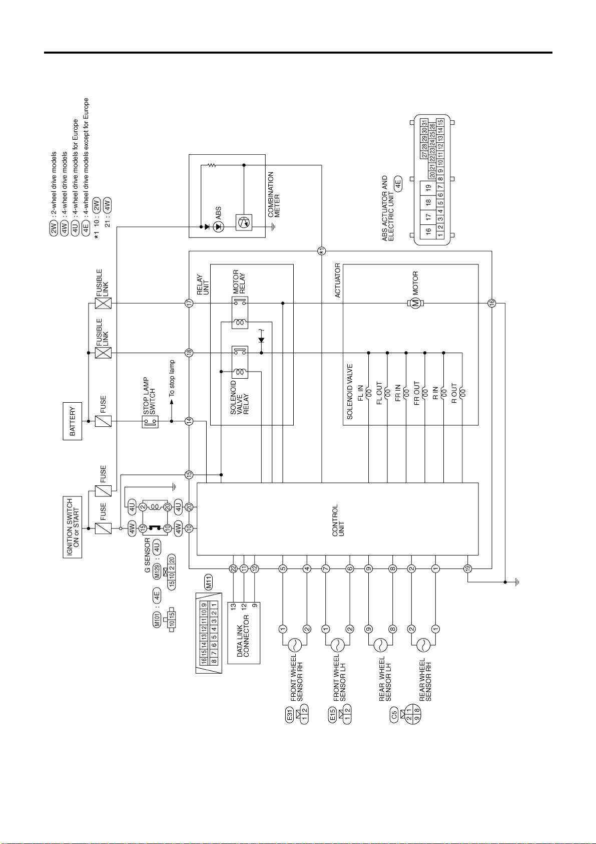
TROUBLE DIAGNOSES
Schematic/4 Wheel Sensors Models
BR-5002
GBR060A
Page 5

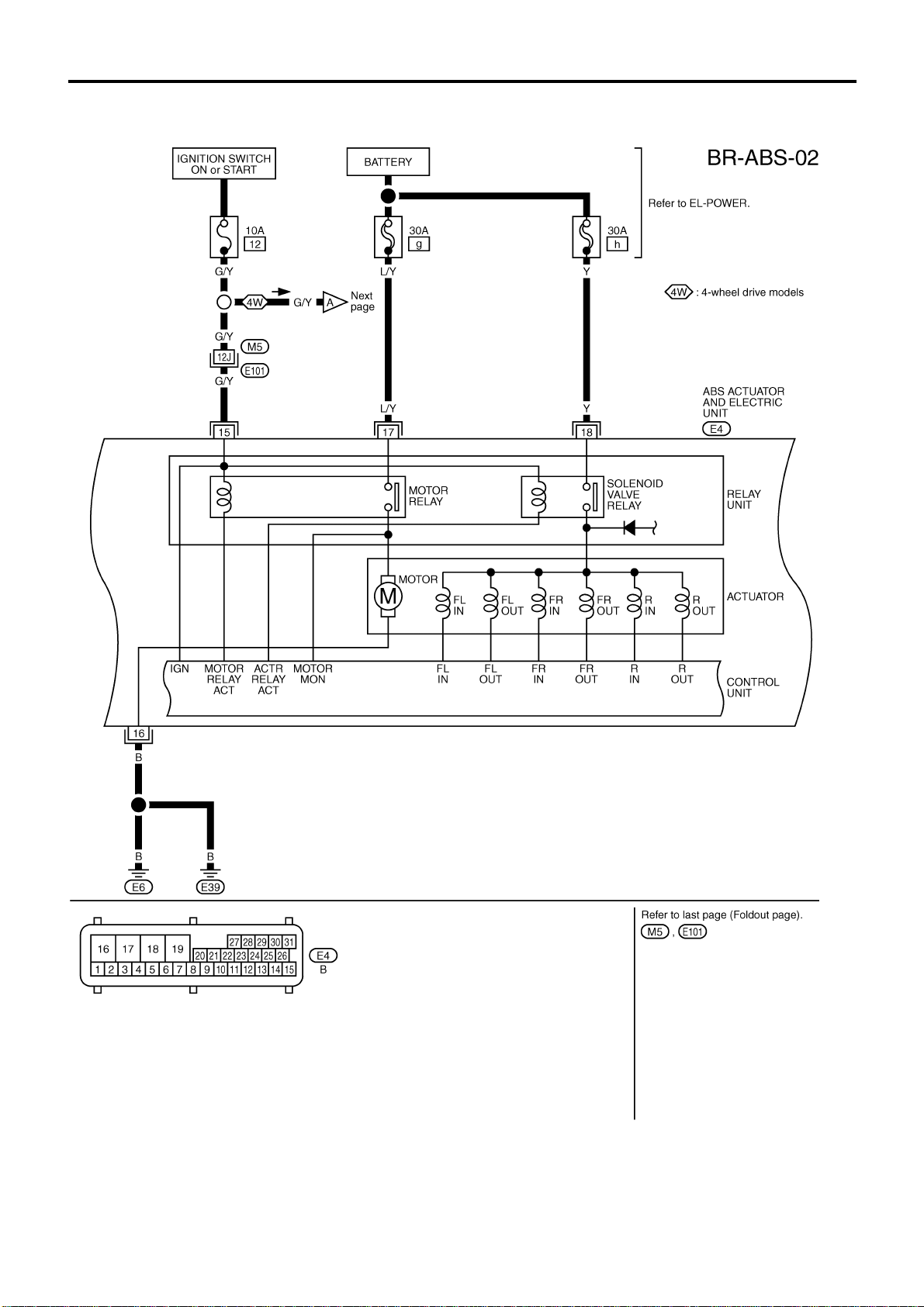
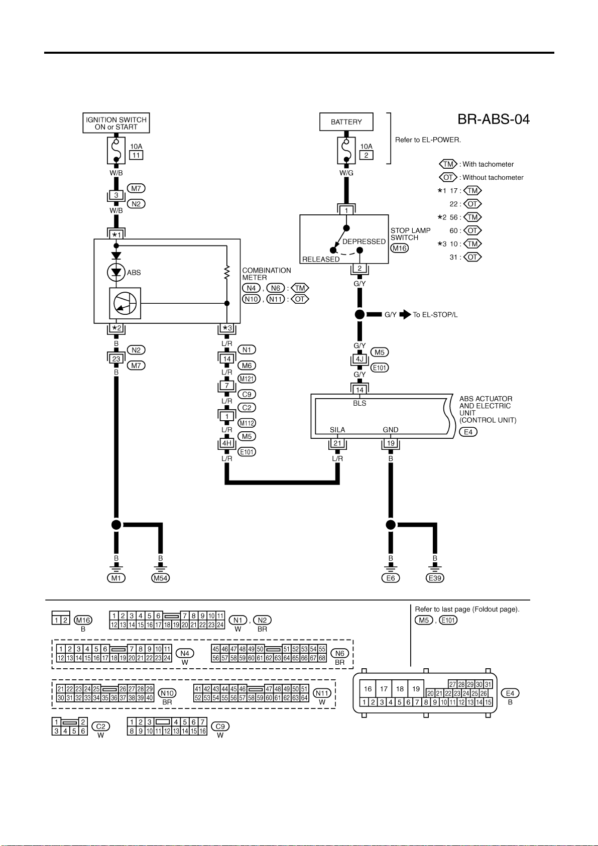
TROUBLE DIAGNOSES
Wiring Diagram — ABS —/4 Wheel Sensors
LHD Models
BR-5003
GBR061A
Page 6
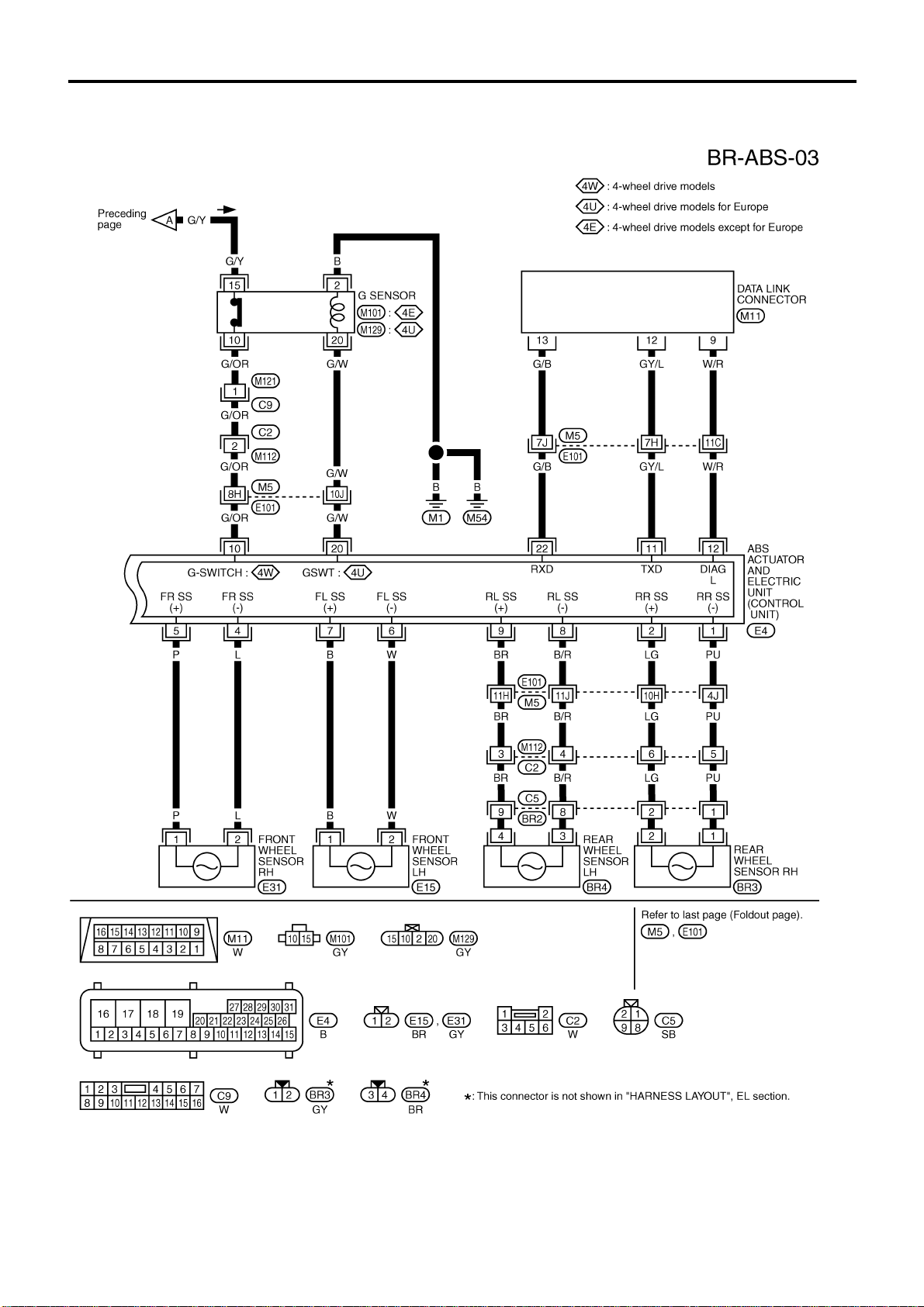
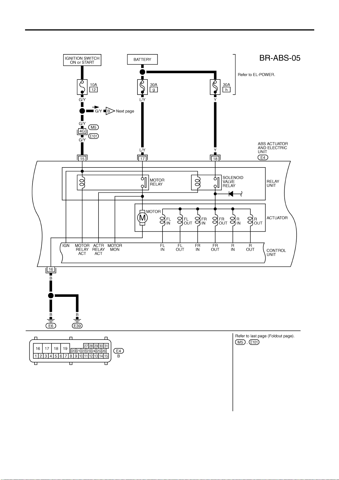
TROUBLE DIAGNOSES
Wiring Diagram — ABS —/4 Wheel Sensors
LHD Models (Cont’d)
BR-5004
GBR062A
Page 7
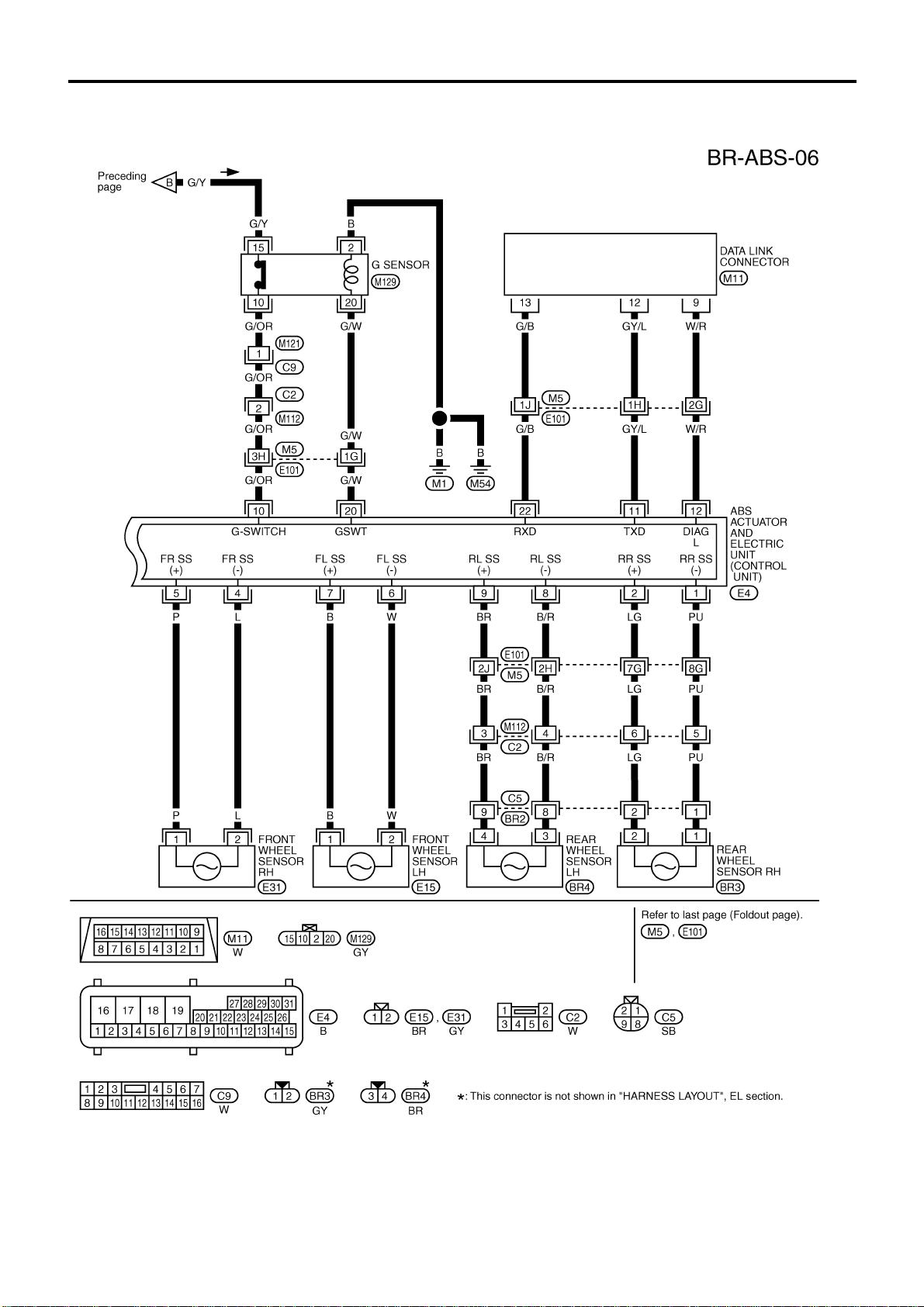
TROUBLE DIAGNOSES
Wiring Diagram — ABS —/4 Wheel Sensors
LHD Models (Cont’d)
BR-5005
GBR063A
Page 8
TROUBLE DIAGNOSES
Wiring Diagram — ABS —/4 Wheel Sensors
RHD Models
BR-5006
GBR064A
Page 9
TROUBLE DIAGNOSES
Wiring Diagram — ABS —/4 Wheel Sensors
RHD Models (Cont’d)
BR-5007
GBR065A
Page 10
TROUBLE DIAGNOSES
Wiring Diagram — ABS —/4 Wheel Sensors
RHD Models (Cont’d)
BR-5008
GBR066A
Page 11
SERVICE DATA AND SPECIFICATIONS (SDS)
General Specifications
2WD MODELS
Destination Europe
Applied model KA24DE YD25 KA24DE YD25
Front brake
Type CL28VD CL33VD
Cylinder bore diameter mm (in) 42.8 (1.685) x 2 46.4 (1.827) x 2
Pad dimension mm (in)
Length x width x thickness
Rotor outer diameter x thickness
Rear brake
Type LT26B LT30A
Wheel cylinder bore diameter
Lining dimension mm (in)
Length x width x thickness
Drum inner diameter mm (in) 260.0 (10.24) 295.0 (11.61)
Master cylinder bore diameter
Control valve
Type LSV
Split point x reducing ratio
kPa (bar, kg/cm
Brake booster
Model M195T M215T
Diaphragm diameter mm (in)
Recommended brake fluid DOT 3 or DOT 4
mm (in)
mm (in)
mm (in)
2
, psi)
249.6 x 40 x 5.5 (9.83 x 1.57 x 0.217) 296 x 50 x 6.1 (11.65 x 1.97 x 0.240)
146.6 x 48.5 x 10
(5.77 x 1.909 x 0.39)
260 x 26 (10.24 x 1.02) 283 x 28 (11.14 x 1.10)
22.22 (7/8)
With ABS: 23.81 (15/16)
Without ABS: 25.4 (1)
(Variable) x 0.15
Primary: 205 (8.07)
Secondary: 180 (7.09)
132.0 x 52.5 x 11 (5.20 x 2.067 x 0.43)
25.4 (1)
Primary: 230 (9.06)
Secondary: 205 (8.07)
BR-5009
Page 12

SERVICE DATA AND SPECIFICATIONS (SDS)
General Specifications (Cont’d)
4WD MODELS
Destination Europe
Applied model KA24DE YD25
Front brake
Type CL33VD
Cylinder bore diameter mm (in) 46.4 (1.827) x 2
Pad dimension mm (in)
Length x width x thickness
Rotor outer diameter x thickness
Rear brake
Type LT30A
Wheel cylinder bore diameter
Lining dimension mm (in)
Length x width x thickness
Drum inner diameter mm (in) 295 (11.61)
Master cylinder bore diameter
Control valve
Type LSV
Split point x reducing ratio
kPa (bar, kg/cm
Brake booster
Model M215T
Diaphragm diameter mm (in)
Recommended brake fluid DOT 3 or DOT 4
mm (in)
mm (in)
mm (in)
2
, psi)
132.0 x 52.5 x 11 (5.20 x 2.067 x 0.43)
283 x 28 (11.14 x 1.10)
22.22 (7/8)
296.0 x 50.0 x 6.1 (11.65 x 1.969 x 0.240)
25.4 (1)
(Variable) x 0.15
Primary: 230 (9.06)
Secondary: 205 (8.07)
BR-5010
Page 13

<SUPPLEMENT-V>
BODY & TRIM
MODIFICATION NOTICE:
Stylish guard bar has been added.
CONTENTS
EXTERIOR...........................................................5002
Stylish Guard Bar.............................................5002
SECTION
Front Seat ........................................................5003
Rear Seat.........................................................5004
BT
BT
Page 14
EXTERIOR
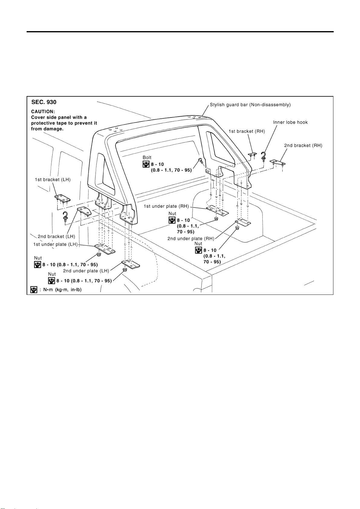
Stylish Guard Bar
REMOVAL — Stylish guard bar assembly
1
Remove nuts of guard bar (left).
V
2
Remove nuts of guard bar (right).
V
3
Remove bolt of guard bar (right).
V
4
Remove stylish guard bar assembly.
V
PIIA6340E
BT-5002
Page 15
EXTERIOR
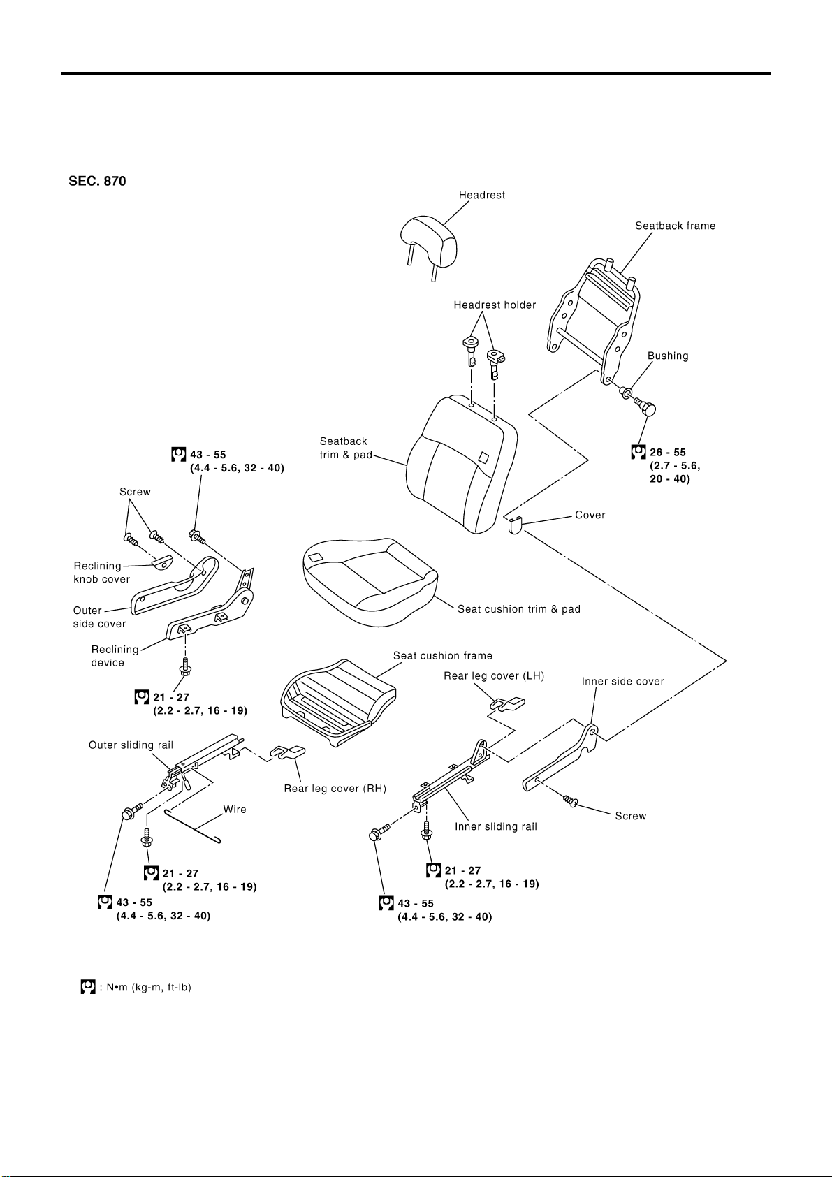
● When removing or installing the seat trim, carefully handle it to keep dirt out and avoid damage.
Front Seat
BT-5003
PIIB0901E
Page 16
EXTERIOR
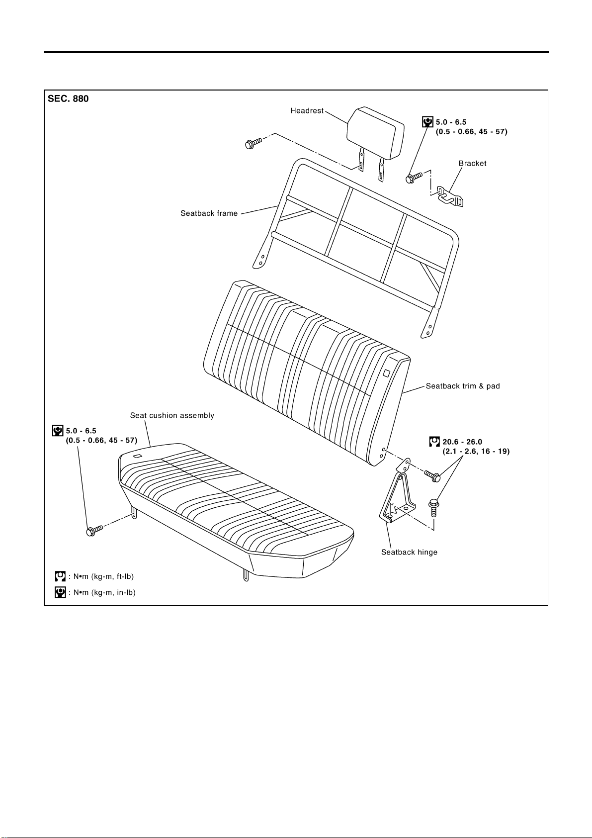
Rear Seat
BT-5004
PIIB0902E
Page 17

<SUPPLEMENT-V>
ELECTRICAL SYSTEM
MODIFICATION NOTICE:
● Wiring diagrams have been changed.
● Harness layouts have been changed.
CONTENTS
INTERIOR ROOM LAMP.....................................5002
Wiring Diagram - ROOM/L -............................5002
ILLUMINATION....................................................5003
Wiring Diagram - ILL -/LHD Models................5003
POWER WINDOW...............................................5005
Schematic/With Interruption Detection
Function ...........................................................5005
Wiring Diagram - WINDOW -/With Interruption
Detection Function...........................................5006
SECTION
THEFT WARNING SYSTEM ...............................5010
Wiring Diagram - PRWIRE -............................5010
HARNESS LAYOUT............................................5012
Main Harness...................................................5012
Engine Room Harness.....................................5018
Room Lamp Harness/LHD Models..................5026
EL
EL
Page 18
INTERIOR ROOM LAMP
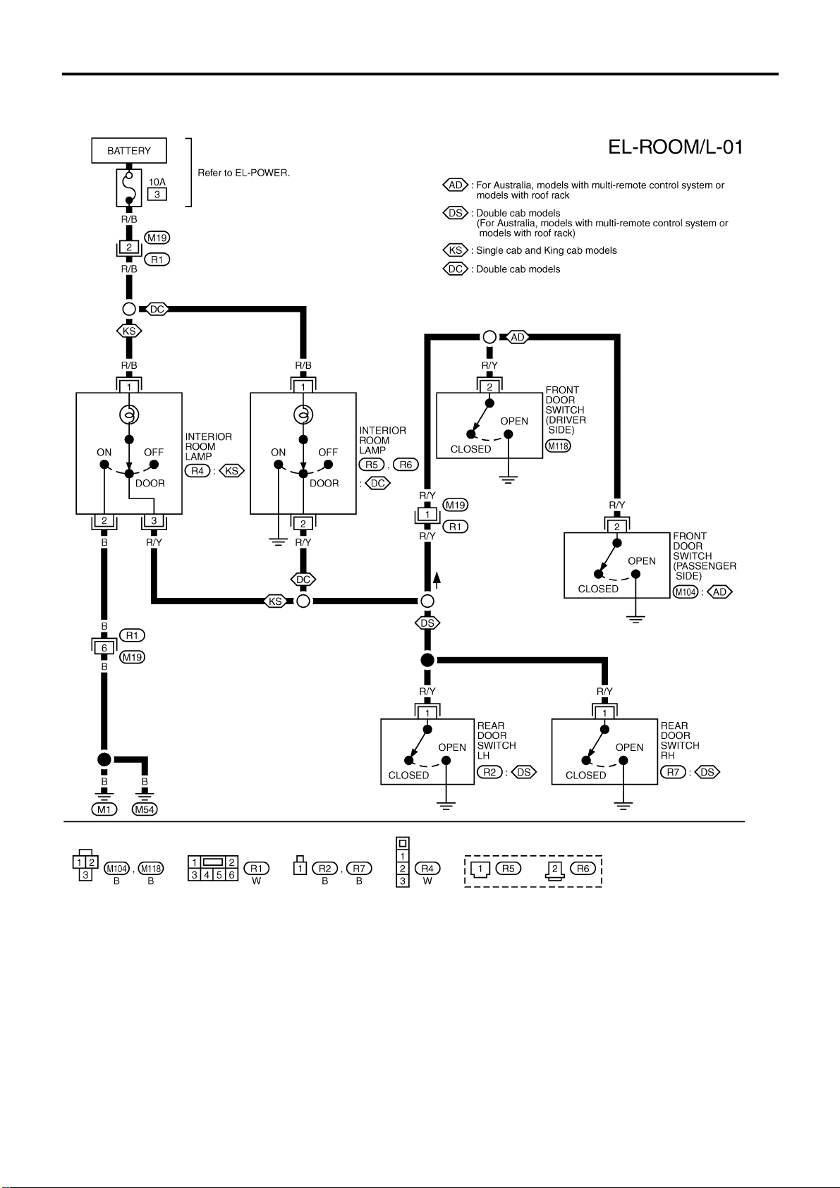
Wiring Diagram — ROOM/L —
EL-5002
GEL924A
Page 19
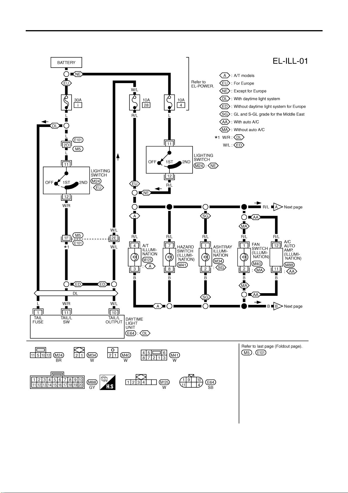
ILLUMINATION
Wiring Diagram — ILL —/LHD Models
EL-5003
GEL675A
Page 20
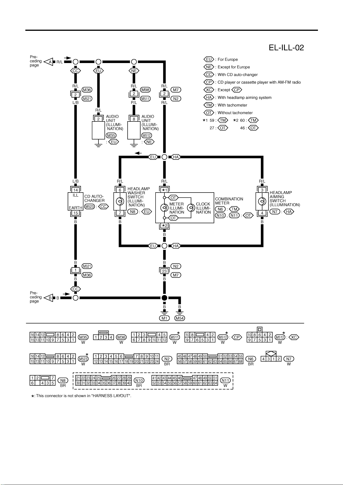
ILLUMINATION
Wiring Diagram — ILL —/LHD Models
(Cont’d)
EL-5004
GEL676A
Page 21
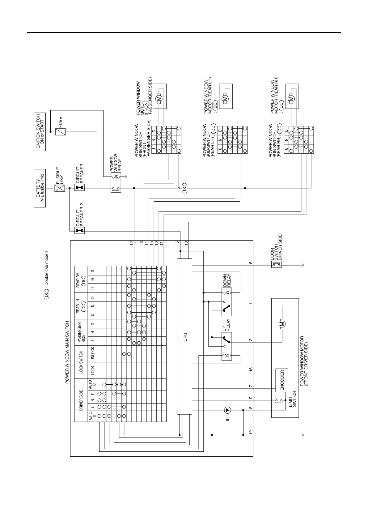
POWER WINDOW
Schematic/With Interruption Detection
Function
EL-5005
GEL925A
Page 22
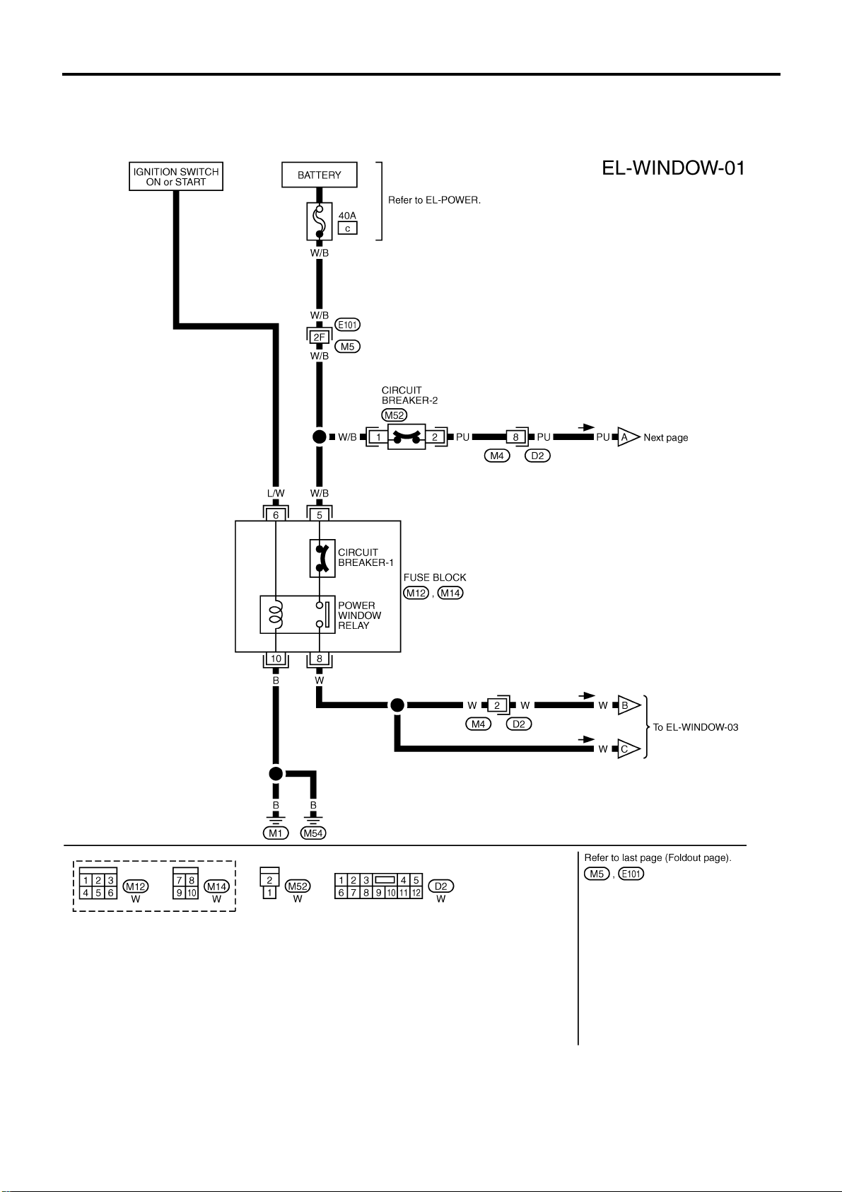
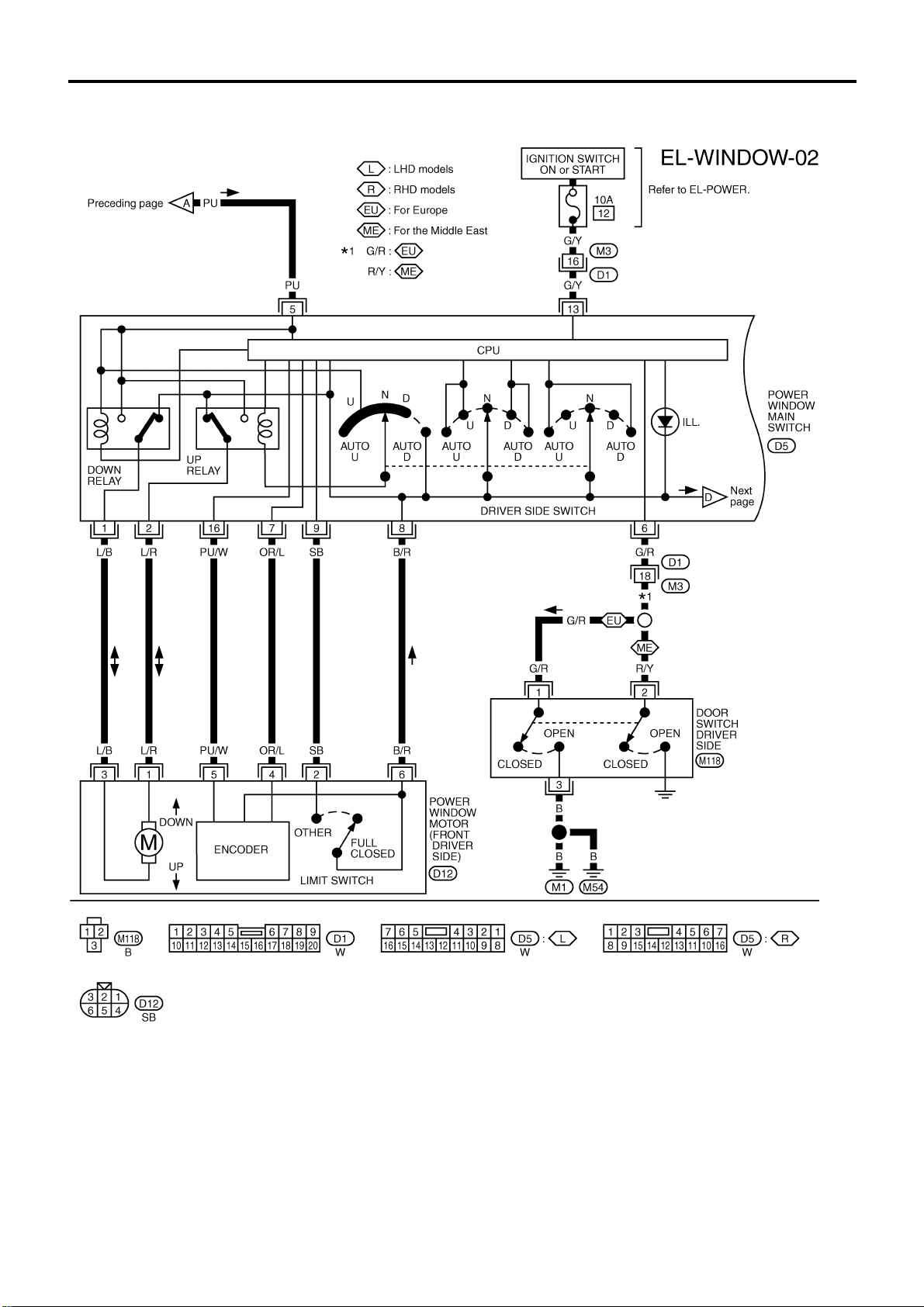
POWER WINDOW
Wiring Diagram — WINDOW —/With
Interruption Detection Function
EL-5006
GEL926A
Page 23
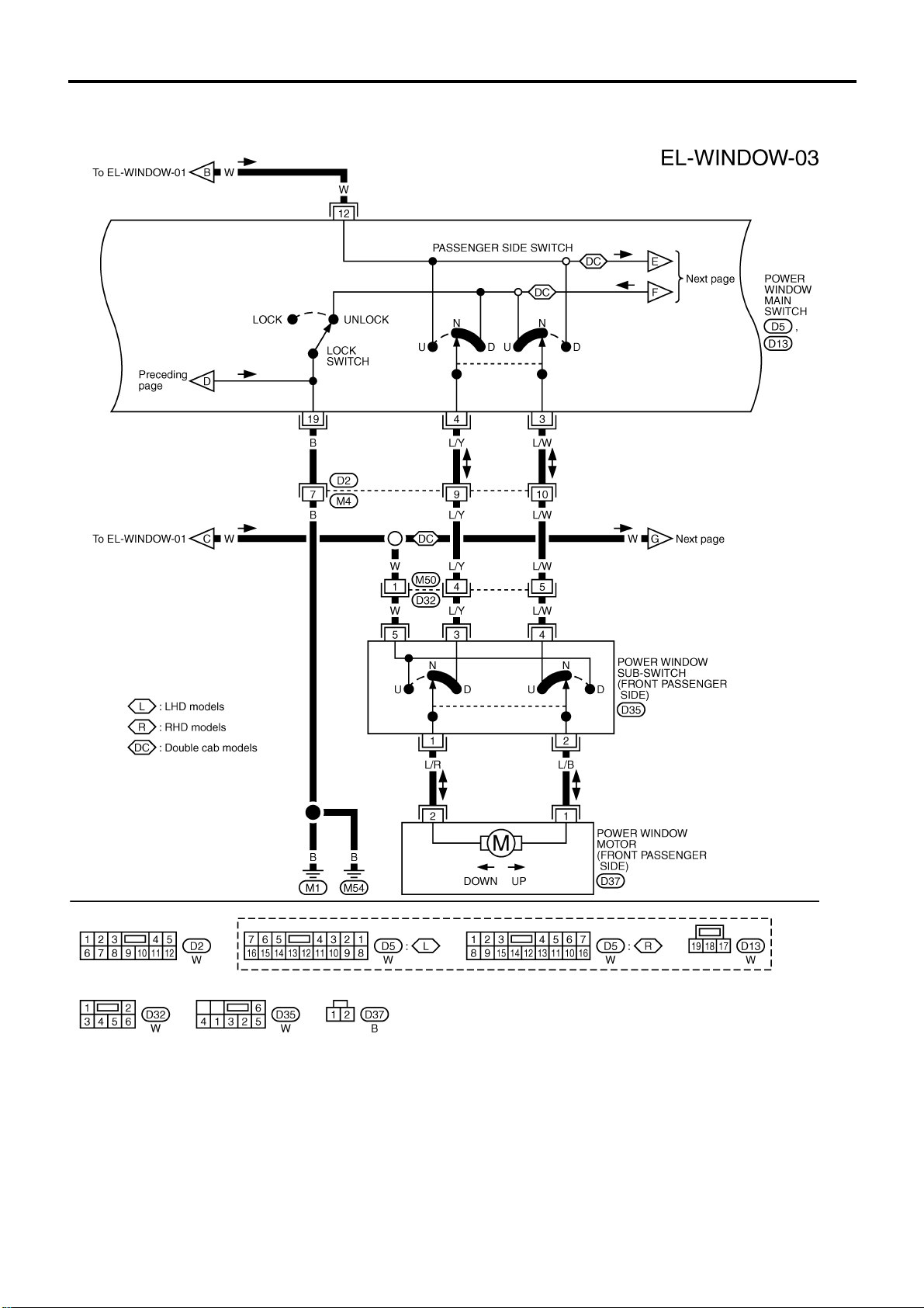
POWER WINDOW
Wiring Diagram — WINDOW —/With
Interruption Detection Function (Cont’d)
EL-5007
GEL927A
Page 24
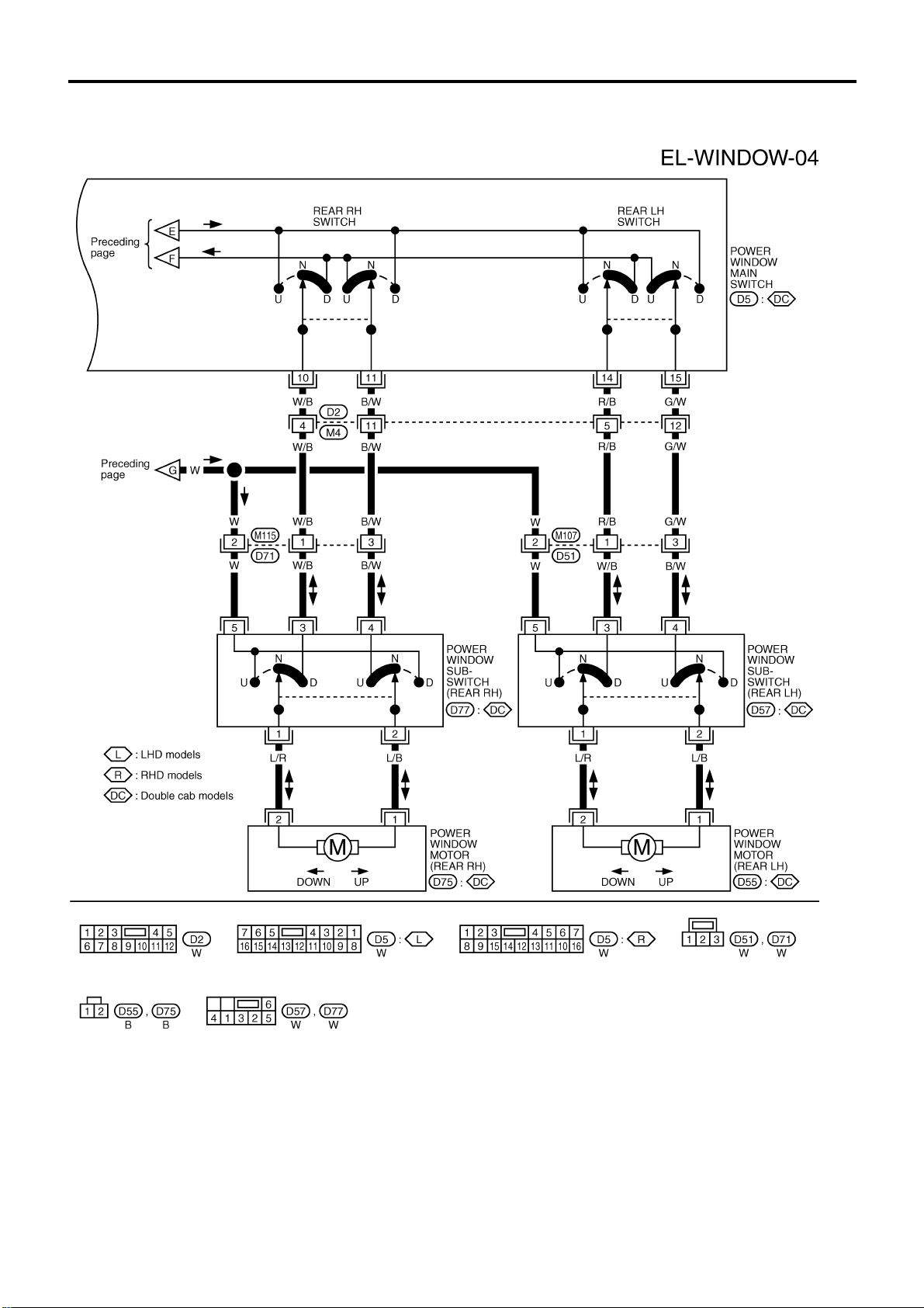
POWER WINDOW
Wiring Diagram — WINDOW —/With
Interruption Detection Function (Cont’d)
EL-5008
GEL928A
Page 25
POWER WINDOW
Wiring Diagram — WINDOW —/With
Interruption Detection Function (Cont’d)
EL-5009
GEL929A
Page 26
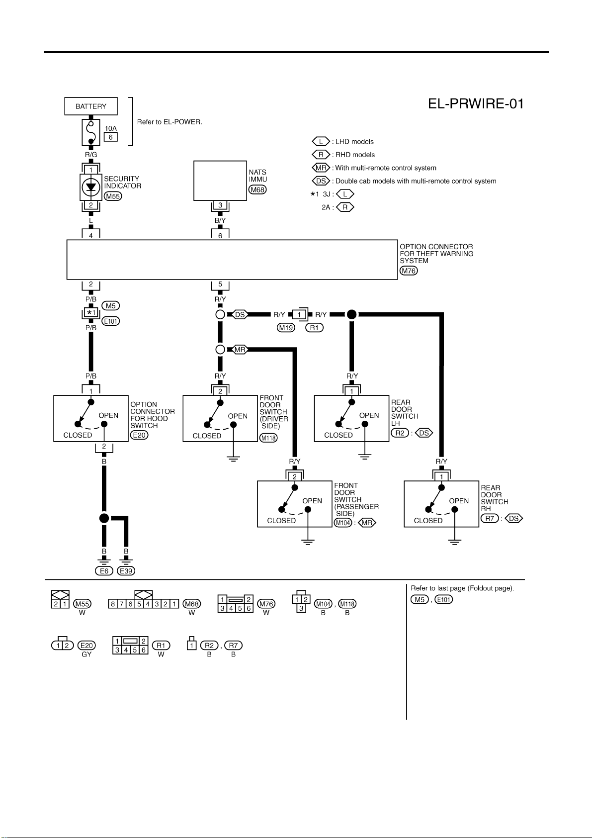
THEFT WARNING SYSTEM
Wiring Diagram — PRWIRE —
EL-5010
GEL930A
Page 27

NOTE
THEFT WARNING SYSTEM
EL-5011
Page 28
HARNESS LAYOUT
Main Harness
INSTRUMENT PANEL — LHD MODELS
EL-5012
HEL082C
Page 29
HARNESS LAYOUT
Main Harness (Cont’d)
EL-5013
HEL083C
Page 30

HARNESS LAYOUT
Main Harness (Cont’d)
INSTRUMENT PANEL — RHD MODELS
EL-5014
HEL084C
Page 31

HARNESS LAYOUT
Main Harness (Cont’d)
EL-5015
HEL085C
Page 32

BODY SIDE — LHD MODELS
HARNESS LAYOUT
Main Harness (Cont’d)
EL-5016
HEL086C
Page 33

BODY SIDE — RHD MODELS
HARNESS LAYOUT
Main Harness (Cont’d)
EL-5017
HEL087C
Page 34

HARNESS LAYOUT
LHD MODELS — GASOLINE ENGINE
Engine Room Harness
EL-5018
HEL088C
Page 35

HARNESS LAYOUT
Engine Room Harness (Cont’d)
EL-5019
HEL089C
Page 36

LHD MODELS — DIESEL ENGINE
HARNESS LAYOUT
Engine Room Harness (Cont’d)
EL-5020
HEL045C
Page 37

HARNESS LAYOUT
Engine Room Harness (Cont’d)
EL-5021
HEL090C
Page 38

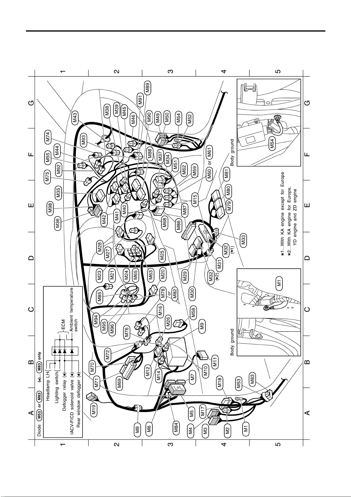
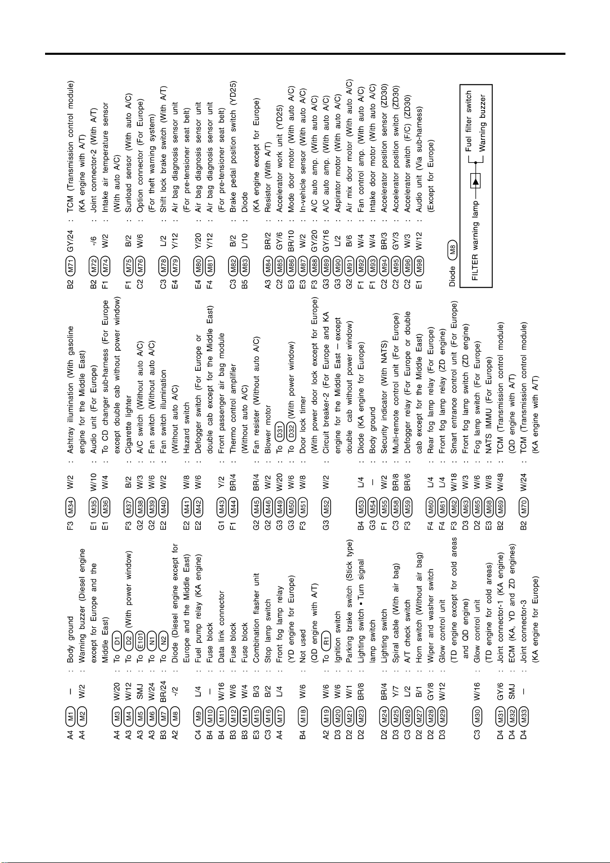
HARNESS LAYOUT
RHD MODELS — GASOLINE ENGINE
Engine Room Harness (Cont’d)
EL-5022
HEL091C
Page 39

HARNESS LAYOUT
Engine Room Harness (Cont’d)
EL-5023
HEL092C
Page 40

RHD MODELS — DIESEL ENGINE
HARNESS LAYOUT
Engine Room Harness (Cont’d)
EL-5024
HEL968B
Page 41

HARNESS LAYOUT
Engine Room Harness (Cont’d)
EL-5025
HEL093C
Page 42

DOUBLE CAB
HARNESS LAYOUT
Room Lamp Harness/LHD Models
HEL094C
EL-5026
Page 43

WIRING DIAGRAM CODES (CELL CODES)
HARNESS LAYOUT
Use the chart below to find out what each wiring diagram code
stands for.
Refer to the wiring diagram code in the alphabetical index to find
the location (page number) of each wiring diagram.
Code Section Wiring Diagram Name
ABS BR Anti-lock Brake System
A/C, M HA Manual Air Conditioner
FICD EC IACV-FICD Solenoid Valve
GLOW EC Quick-glow System
ILL EL Illumination
PRWIRE EL Theft Warning System Pre-wire
ROOM/L EL Interior Room Lamp
SRS RS Supplemental Restraint System
WINDOW EL Power Window
EL-5027
Page 44

<SUPPLEMENT-V>
ELECTRICAL SYSTEM
MODIFICATION NOTICE:
● Wiring diagrams have been changed.
● Harness layouts have been changed.
CONTENTS
INTERIOR ROOM LAMP.....................................5002
Wiring Diagram - ROOM/L -............................5002
ILLUMINATION....................................................5003
Wiring Diagram - ILL -/LHD Models................5003
POWER WINDOW...............................................5005
Schematic/With Interruption Detection
Function ...........................................................5005
Wiring Diagram - WINDOW -/With Interruption
Detection Function...........................................5006
SECTION
THEFT WARNING SYSTEM ...............................5010
Wiring Diagram - PRWIRE -............................5010
HARNESS LAYOUT............................................5012
Main Harness...................................................5012
Engine Room Harness.....................................5018
Room Lamp Harness/LHD Models..................5026
EL
EL
Page 45

INTERIOR ROOM LAMP
Wiring Diagram — ROOM/L —
EL-5002
GEL924A
Page 46

ILLUMINATION
Wiring Diagram — ILL —/LHD Models
EL-5003
GEL675A
Page 47

ILLUMINATION
Wiring Diagram — ILL —/LHD Models
(Cont’d)
EL-5004
GEL676A
Page 48

POWER WINDOW
Schematic/With Interruption Detection
Function
EL-5005
GEL925A
Page 49

POWER WINDOW
Wiring Diagram — WINDOW —/With
Interruption Detection Function
EL-5006
GEL926A
Page 50

POWER WINDOW
Wiring Diagram — WINDOW —/With
Interruption Detection Function (Cont’d)
EL-5007
GEL927A
Page 51

POWER WINDOW
Wiring Diagram — WINDOW —/With
Interruption Detection Function (Cont’d)
EL-5008
GEL928A
Page 52

POWER WINDOW
Wiring Diagram — WINDOW —/With
Interruption Detection Function (Cont’d)
EL-5009
GEL929A
Page 53

THEFT WARNING SYSTEM
Wiring Diagram — PRWIRE —
EL-5010
GEL930A
Page 54

NOTE
THEFT WARNING SYSTEM
EL-5011
Page 55

HARNESS LAYOUT
Main Harness
INSTRUMENT PANEL — LHD MODELS
EL-5012
HEL082C
Page 56

HARNESS LAYOUT
Main Harness (Cont’d)
EL-5013
HEL083C
Page 57

HARNESS LAYOUT
Main Harness (Cont’d)
INSTRUMENT PANEL — RHD MODELS
EL-5014
HEL084C
Page 58

HARNESS LAYOUT
Main Harness (Cont’d)
EL-5015
HEL085C
Page 59

BODY SIDE — LHD MODELS
HARNESS LAYOUT
Main Harness (Cont’d)
EL-5016
HEL086C
Page 60

BODY SIDE — RHD MODELS
HARNESS LAYOUT
Main Harness (Cont’d)
EL-5017
HEL087C
Page 61

HARNESS LAYOUT
LHD MODELS — GASOLINE ENGINE
Engine Room Harness
EL-5018
HEL088C
Page 62

HARNESS LAYOUT
Engine Room Harness (Cont’d)
EL-5019
HEL089C
Page 63

LHD MODELS — DIESEL ENGINE
HARNESS LAYOUT
Engine Room Harness (Cont’d)
EL-5020
HEL045C
Page 64

HARNESS LAYOUT
Engine Room Harness (Cont’d)
EL-5021
HEL090C
Page 65

HARNESS LAYOUT
RHD MODELS — GASOLINE ENGINE
Engine Room Harness (Cont’d)
EL-5022
HEL091C
Page 66

HARNESS LAYOUT
Engine Room Harness (Cont’d)
EL-5023
HEL092C
Page 67

RHD MODELS — DIESEL ENGINE
HARNESS LAYOUT
Engine Room Harness (Cont’d)
EL-5024
HEL968B
Page 68

HARNESS LAYOUT
Engine Room Harness (Cont’d)
EL-5025
HEL093C
Page 69

DOUBLE CAB
HARNESS LAYOUT
Room Lamp Harness/LHD Models
HEL094C
EL-5026
Page 70

WIRING DIAGRAM CODES (CELL CODES)
HARNESS LAYOUT
Use the chart below to find out what each wiring diagram code
stands for.
Refer to the wiring diagram code in the alphabetical index to find
the location (page number) of each wiring diagram.
Code Section Wiring Diagram Name
ABS BR Anti-lock Brake System
A/C, M HA Manual Air Conditioner
FICD EC IACV-FICD Solenoid Valve
GLOW EC Quick-glow System
ILL EL Illumination
PRWIRE EL Theft Warning System Pre-wire
ROOM/L EL Interior Room Lamp
SRS RS Supplemental Restraint System
WINDOW EL Power Window
EL-5027
Page 71

<SUPPLEMENT-V>
ENGINE MECHANICAL
SECTION
MODIFICATION NOTICE:
● YD25DDTi engine information has been added.
For information not included here, refer to information for YD25DDTi engine in D22 Supplement-VI 1st
Revision Service Manual (SM1E-1D22FG1).
EM
CONTENTS
EM
YD
CYLINDER HEAD................................................5002
Inspection.........................................................5002
CYLINDER BLOCK .............................................5003
Inspection.........................................................5003
SERVICE DATA AND SPECIFICATIONS
(SDS)....................................................................5005
Cylinder Head ..................................................5005
Cylinder Block..................................................5006
Piston, Piston Ring and Piston Pin..................5006
Page 72

SEM496G
CYLINDER HEAD
Inspection
CYLINDER HEAD DISTORTION
Clean surface of cylinder head. Use a reliable straightedge and
feeler gauge to check the flatness of cylinder head surface.
Check along six positions shown in the figure.
Head surface flatness: Limit 0.1 mm (0.004 in)
If beyond the specified limit, resurface or replace it.
The limit for cylinder head resurfacing is determined by the
cylinder block resurfacing.
Resurfacing limit:
Amount of cylinder head resurfacing is “A”.
Amount of cylinder block resurfacing is “B”.
The maximum limit:A+B=0.07 mm (0.0028 in)
After resurfacing cylinder head, check that camshaft rotates
freely by hand. If resistance is felt, cylinder head must be
replaced.
Nominal cylinder head height:
153.9 - 154.1 mm (6.059 - 6.067 in)
YD
EM-5002
Page 73

JEM206G
CYLINDER BLOCK
Inspection
PISTON-TO-BORE CLEARANCE
1. Using a bore gauge, measure cylinder bore in X and Y directions at A, B and C for wear, out-of-round and taper.
Cylinder bore inner diameter:
Standard
89.000 - 89.030 mm (3.5039 - 3.5051 in)
Wear limit
0.07 mm (0.0028 in)
If it exceeds the limit, rebore all cylinders. Replace cylinder
block if necessary.
Out-of-round (Difference between X and Y):
Limit 0.015 mm (0.0006 in)
Taper (Difference between A and C):
Limit 0.010 mm (0.0004 in)
2. Check for scratches and seizure. If seizure is found, hone it.
YD
SEM899G
SEM258C
3. Measure piston skirt diameter.
Piston diameter “A”:
Standard
88.925 - 88.955 mm (3.5010 - 3.5022 in)
Measuring point “a” (Distance from the top):
59.0 mm (2.323 in)
4. Check that piston-to-bore clearance is within specification.
● Calculate the clearance by using outer diameter at piston
skirt and inner diameter of cylinder (direction of X, point B):
Piston-to-bore clearance = Cylinder bore − Piston
diameter “A”
Standard [at room temperature 20°C (68°F)]:
0.065 - 0.085 mm (0.0026 - 0.0033 in)
● If the value is out of the specified range, replace piston and
piston pin assembly.
JEM208G
● If cylinder block or pistons are replaced with new ones, select
piston as follows:
When using a new cylinder block:
● Identify the cylinder bore grade (No. 1, 2, or 3) on LH surface
at the rear of cylinder block and select a piston of the same
grade.
● The part No. of piston is specified together with the piston pin
as an assembly.
EM-5003
Page 74

SEM508GB
CYLINDER BLOCK
Inspection (Cont’d)
When re-using a removed cylinder block:
● Measure the inner diameter of the cylinder block bore.
● Determine the bore grade by comparing the measurement
with the values under “Cylinder bore ID” of the table below.
Choose a piston of the same grade.
Selective fitting for piston:
Unit: mm (in)
Grade (punched) 1 2 3
Cylinder bore ID
Piston OD
89.000 - 89.010
(3.5039 - 3.5043)
88.925 - 88.935
(3.5010 - 3.5014)
5. Determine piston oversize according to amount of cylinder
wear.
● For oversize pistons, 0.25 and 0.5 OS [0.25 mm (0.0098
in), 0.5 mm (0.0197 in) oversize] are available as service
parts. Refer to SDS, EM-5006. When using an oversize
piston, hone cylinder so that the clearance between piston and cylinder becomes the specified value. Be sure to
use appropriate oversize piston ring for the oversize piston.
6. Cylinder bore size is determined by adding piston-to-bore
clearance to piston diameter “A”.
Rebored size calculation:D=A+B−C
where,
D: Bored diameter
A: Piston diameter as measured
B: Piston-to-bore clearance
C: Honing allowance 0.02 mm (0.0008 in)
7. Cut cylinder bores.
● When any cylinder needs boring, all other cylinders
must also be bored.
● Do not cut too much out of cylinder bore at a time. Cut
only 0.05 mm (0.0020 in) or so in diameter at a time.
8. Hone cylinders to obtain specified piston-to-bore clearance.
9. Measure finished cylinder bore for out-of-round and taper.
● Measurement should be done after cylinder bore cools
down.
89.010 - 89.020
(3.5043 - 3.5047)
88.935 - 88.945
(3.5014 - 3.5018)
89.020 - 89.030
(3.5047 - 3.5051)
88.945 - 88.955
(3.5018 - 3.5022)
YD
EM-5004
Page 75

SERVICE DATA AND SPECIFICATIONS (SDS)
Cylinder Head
Standard Limit
Head surface distortion Less than 0.03 (0.0012) 0.1 (0.004)
YD
Unit: mm (in)
JEM204G
EM-5005
Page 76

SERVICE DATA AND SPECIFICATIONS (SDS)
Cylinder Block
Surface flatness
Cylinder bore Inner diameter
Out-of-round (Difference between X and Y) Less than 0.015 (0.0006)
Taper (Difference between A and C) Less than 0.010 (0.0004)
Standard Less than 0.03 (0.0012)
Limit 0.1 (0.004)
Grade No. 1 89.000 - 89.010 (3.5039 - 3.5043)
Standard
Wear limit 0.07 (0.0028)
Grade No. 2 89.010 - 89.020 (3.5043 - 3.5047)
Grade No. 3 89.020 - 89.030 (3.5047 - 3.5051)
YD
Unit: mm (in)
SEM899G
Piston, Piston Ring and Piston Pin
AVAILABLE PISTON
Grade No. 1 88.925 - 88.935 (3.5010 - 3.5014)
Grade No. 2 88.935 - 88.945 (3.5014 - 3.5018)
Piston skirt diameter “A” Standard
“a” dimension 59.0 (2.323)
Piston clearance to cylinder block 0.065 - 0.085 (0.0026 - 0.0033)
Grade No. 3 88.945 - 88.955 (3.5018 - 3.5022)
0.25 (0.0098) oversize (Service) 89.175 - 89.205 (3.5108 - 3.5120)
0.50 (0.0197) oversize (Service) 89.425 - 89.455 (3.5207 - 3.5218)
Unit: mm (in)
SEM882E
EM-5006
Page 77

SUPER MULTIPLE JUNCTION (SMJ)
Terminal Arrangement
GEL314A
Page 78

CONTROL UNITS
Terminal Arrangement
GEL852A
Page 79

<SUPPLEMENT-V>
CONTENTS
CONSULT-II CHECKING SYSTEM.....................5002
Function and System Application ....................5002
Nickel Metal Hydride Battery Replacement.....5002
Checking Equipment........................................5003
GENERAL INFORMATION
SECTION
CONSULT-II Data Link Connector (DLC)
Circuit...............................................................5003
Model Variation................................................5004
Identification Number.......................................5006
GI
GI
This modification has been included in production starting with the following vehicle identification numbers
(Chassis number):
For Israel
JN1CPGD224X560201
JN1CPUD224X570401
For Europe
JN1APGD22U0056701
JN1APUD22U0037101
JN1BPGD22U0033201
JN1BPUD22U0090001
JN1CPGD22U0048001
JN1CPUD22U0088401
JN1ADGD22U0021601
JN1BDGD22U0031601
JN1BDUD22U0031801
JN1CDUD22U0031701
Page 80

CONSULT-II CHECKING SYSTEM
Function and System Application
Diagnostic test
mode
Work support
Self-diagnostic
results
Trouble diagnostic record
ECU discriminated No.
Data monitor
DTC work support
Active test
ECU (ECM) part
number
Function test
x: Applicable
Function ENGINE A/T ABS AIR BAG
This mode enables a technician to
adjust some devices faster and more
accurate by following the indications
on CONSULT-II.
Self-diagnostic results can be read
and erased quickly.
Current self-diagnostic results and all
trouble diagnostic records previously
stored can be read.
Classification number of a replacement ECU can be read to prevent an
incorrect ECU from being installed.
Input/Output data in the ECU (ECM)
can be read.
This mode enables a technician to
set operating conditions to confirm
self-diagnosis status/results.
Diagnostic Test Mode in which CONSULT-II drives some actuators apart
from the ECMs and also shifts some
parameters in a specified range.
ECU (ECM) part number can be
read.
Conducted by CONSULT-II instead
of a technician to determine whether
each system is “OK” or “NG” (No
Good).
Nickel Metal Hydride Battery Replacement
xx——
xxxx
——— x
——— x
xxx—
—x——
x—x—
xxx—
xxxx
CONSULT-II contains a nickel metal hydride battery. When replacing the battery obey the following:
WARNING:
Replace the nickel metal hydride battery with Genuine CONSULT-II battery only. Use of another battery may present a risk of fire or explosion. The battery may present a fire or chemical burn hazard
if mistreated. Do not recharge, disassemble of dispose of in fire.
Keep the battery out of reach of children and discard used battery conforming to the local regulations.
GI-5002
Page 81

CONSULT-II CHECKING SYSTEM
Checking Equipment
When ordering the below equipment, contact your NISSAN distributor.
Tool name Description
NISSAN CONSULT-II
1
CONSULT-II unit (Tester internal soft:
V
Resident version 3.3.0) and accessories
2
Program card AED01C for diagnostic,
V
AEN00A/00B for NATS.
To confirm the best combination of
those softwares, refer to CONSULT-II
Operation Manual.
SGI083A
NOTE:
● The CONSULT-II must be used in conjunction with a program card.
CONSULT-II does not require loading (Initialization) procedure.
● Be sure the CONSULT-II is turned off before installing or removing a program card.
CONSULT-II Data Link Connector (DLC)
Circuit
INSPECTION PROCEDURE
If the CONSULT-II cannot diagnose the system properly, check the following items.
Symptom Check item
CONSULT-II cannot access
any system.
CONSULT-II cannot access
individual system. (Other systems can be accessed.)
● CONSULT-II DLC power supply circuit (Terminal 8) and ground circuit (Terminal 4)
(For detailed circuit, refer to EC section “MIL & Data Link Connectors”.)
● CONSULT-II DDL cable
● CONSULT-II program card (Check the appropriate CONSULT-II program card for the system.
Refer to “Checking Equipment” above.)
● Power supply and ground circuit for the control unite of the system
(For detailed circuit, refer to wiring diagram for each system.)
● Open or short circuit between the system and CONSULT-II DLC
(For detailed circuit, refer to wiring diagram for each system.)
SOM801
GI-5003
Page 82

C200
IDENTIFICATION INFORMATION
CONSULT-II CHECKING SYSTEM
Model Variation
Transfer
Engine Transmission Differential carrier
KA24DE FS5W71C
—
AVLGLCFD22UQL YD25DDTi FS5R30A
AVLGLDFD22UQL AVLGRDFD22UQL YD25DDTi FS5R30A
ABGGLCFD22EQL
ABGGLDFD22EQL — KA24DE FS5W71C
DX
STD
DX BBGGLDFD22EQN — KA24DE FS5W71C
DX BVLGLDFD22UQN BVLGRDFD22UQN YD25DDTi FS5R30A
DX BVLGLDFD22UQG —
YD25DDTi FS5R30A
ST BVLGLEFD22UQG —
Differential carrier
Engine Transmission
YD25DDTi FS5R30A
ST CVLGLEFD22UQG —
DX CVLGLDFD22UQG —
R180 C200 TX10
YD25DDTi FS5R30AST BVLULEFD22UQN BVLUREFD22UQN
YD25DDTi FS5R30A
Class Model
Cab Wheelbase Grade LH drive RH drive
Destination
PICKUP (2WD)
Single Cab
Long
King Cab
Europe
4WD appearance
4WD appearance
Double Cab DX CVLGLDFD22UQN CVLGRDFD22UQN
Class Model
Destination
PICKUP (4WD)
BBGULDFD22EQN — KA24DE FS5W71C
DX AVLULDFD22UQL AVLURDFD22UQL
STD AVLULCFD22UQL AVLURCFD22UQL
Cab Wheelbase Grade LH drive RH drive Front Rear
Single Cab
GI-5004
BVLULDFD22UQN BVLURDFD22UQN
DX
King Cab
CBGULDFD22EQN — KA24DE FS5W71C
SE BVLULFFD22UQN BVLURFFD22UQN
Long
Europe
CVLULDFD22UQN CVLURDFD22UQN
ST CVLULEFD22UQN CVLUREFD22UQN
SE CVLULFFD22UQN CVLURFFD22UQN
DX
SS CVLULGFD22UQN CVLURGFD22UQN
Double Cab
Page 83

IDENTIFICATION INFORMATION
CONSULT-II CHECKING SYSTEM
Model Variation (Cont’d)
Prefix and suffix designations
(Pickup)
A BG G L C F D22 E W L
Q: Europe
E: Multiport fuel injection system engine
U: Turbocharged engine with intercooler
F: 5-speed floor shift manual transmission
B: 4-speed column shift automatic transmission
A: 4-speed floor shift automatic transmission
C: STD model D: DX model E: GL, ST model F: SE model G: SS model
L: LH drive R: RH drive
G: Long wheelbase (2WD)
U: Long wheelbase (4WD)
BG: KA24DE engine VL: YD25DDTi engine
A: Single Cab B: King Cab C: Double Cab
L: Regular rear body
N: Smooth rear body
G: 4WD appearance model (2WD)
GI-5005
Page 84

IDENTIFICATION INFORMATION
CONSULT-II CHECKING SYSTEM
VEHICLE IDENTIFICATION NUMBER
Prefix and suffix designations
For Israel
JN1 C P G D22 4 X XXXXXX
Model
G: Long wheelbase (2WD) U: Long wheelbase (4WD)
P: YD25DDTi engine
C: Double Cab
JN1: Japan produced vehicle
Identification Number
Vehicle serial number
Manufacturing plant
X: Hiratsuka
Model year
4: 2004, 5: 2005 after November, ’03 production
For Europe
JN1 B P U D22 U O XXXXXX
JN1: Japan produced vehicle
Vehicle serial number
O: Stopgap (no meaning)
U: For Europe
Model
G: Long wheelbase (2WD) U: Long wheelbase (4WD)
D: KA24DE engine P: YD25DDTi engine
A: Single Cab B: King Cab C: Double Cab
GI-5006
Page 85

<SUPPLEMENT-V>
HEATER &
AIR CONDITIONER
SECTION
MODIFICATION NOTICE:
● Wiring diagrams have been changed for LHD models with KA, YD and ZD engines. (manual A/C)
HA
CONTENTS
MANUAL
TROUBLE DIAGNOSES .....................................5002
Circuit Diagram - A/C, M -...............................5002
Wiring Diagram - A/C, M -/LHD Models with
KA, YD and ZD Engines..................................5003
HA
Page 86

TROUBLE DIAGNOSES
Circuit Diagram — A/C, M —
MANUAL
HA-5002
GHA132A
Page 87

TROUBLE DIAGNOSES
Wiring Diagram — A/C, M —/LHD Models
with KA, YD and ZD Engines
MANUAL
HA-5003
GHA056A
Page 88

TROUBLE DIAGNOSES
Wiring Diagram — A/C, M —/LHD Models
with KA, YD and ZD Engines (Cont’d)
MANUAL
HA-5004
GHA057A
Page 89

TROUBLE DIAGNOSES
Wiring Diagram — A/C, M —/LHD Models
with KA, YD and ZD Engines (Cont’d)
MANUAL
HA-5005
GHA133A
Page 90

<SUPPLEMENT-V>
ALPHABETICAL INDEX
SECTION
IDX
IDX
Page 91

ALPHABETICAL INDEX
A
ABS-Wiringdiagram...........................BR-5003
A/Ctroublediagnoses(manualA/C)....HA-5002
A/C,M-Wiringdiagram.......................HA-5003
Anti-lock brake system - Wiring
diagram.............................................BR-5002
C
Cylinderblock.......................................EM-5003
Cylinderhead.......................................EM-5002
E
Exterior..................................................BT-5002
F
Frontseat..............................................BT-5003
H
P
Pistontoboreclearance......................EM-5003
Powerwindow.......................................EL-5005
R
Rearseat...............................................BT-5004
ROOM/L-Wiringdiagram.....................EL-5002
S
Seat,front..............................................BT-5003
Seat,rear...............................................BT-5004
SMJ (super multiple junction) ................. Foldout
SRS-Wiringdiagram...........................RS-5002
Supplemental restraint system - Wiring
diagram.............................................RS-5002
T
THEFT-Wiringdiagram.......................EL-5010
Theftwarningsystem............................EL-5010
Harnesslayout.......................................EL-5012
I
ILL-Wiringdiagram..............................EL-5003
Illumination.............................................EL-5003
Interiorlamp...........................................EL-5002
M
Modelvariation.......................................GI-5004
V
Vehicleidentificationnumber.................GI-5006
W
WiringDiagram(Cellcode)list.............EL-5027
IDX-5002
Page 92

<SUPPLEMENT-V>
RESTRAINT SYSTEM
MODIFICATION NOTICE:
Air bag system wiring diagram has been changed.
CONTENTS
TROUBLE DIAGNOSES - Supplemental
Restraint System (SRS).....................................5002
SECTION
Wiring Diagram - SRS -...................................5002
RS
RS
Page 93

TROUBLE DIAGNOSES — Supplemental Restraint System (SRS)
Wiring Diagram — SRS —
RS-5002
GRS006A
Page 94

TROUBLE DIAGNOSES — Supplemental Restraint System (SRS)
Wiring Diagram — SRS — (Cont’d)
RS-5003
GRS026A
 Loading...