

Page 1

GI
ENGINE CONTROL SYSTEM
MA
EM
SECTION
MODIFICATION NOTICE:
I The SMART C/U - PREVIOUS is applicable for the 2WD models up to serial number 567231 and for the
4WD models up to serial number 584967.
I The SMART C/U - NEW is applicable for the 2WD models from serial number 567231 and for the 4WD
models from serial number 584967.
EC
CONTENTS
TROUBLE DIAGNOSIS - INDEX ....................................8
Alphabetical & P No. Index for DTC ...........................8
PRECAUTIONS .............................................................14
Supplemental Restraint System (SRS) ″AIR
BAG″ and ″SEAT BELT PRE-TENSIONER″.............14
Precautions for On Board Diagnostic (OBD)
System of Engine and A/T.........................................14
Engine Fuel & Emission Control System ..................15
Precautions................................................................16
Wiring Diagrams and Trouble Diagnosis...................17
PREPARATION .............................................................18
Special Service Tools................................................18
Commercial Service Tools.........................................18
ENGINE AND EMISSION CONTROL OVERALL
SYSTEM.........................................................................20
Engine Control Component Parts Location...............20
Circuit Diagram..........................................................24
System Diagram ........................................................26
Vacuum Hose Drawing..............................................27
System Chart.............................................................28
ENGINE AND EMISSION BASIC CONTROL
SYSTEM DESCRIPTION...............................................29
Multiport Fuel Injection (MFI) System .......................29
Electronic Ignition (EI) System ..................................31
Air Conditioning Cut Control......................................32
Fuel Cut Control (at no load & high engine
speed)........................................................................33
Evaporative Emission System...................................33
Positive Crankcase Ventilation..................................39
BASIC SERVICE PROCEDURE...................................40
Fuel Pressure Release..............................................40
Fuel Pressure Check.................................................40
Fuel Pressure Regulator Check ................................41
Injector.......................................................................42
How to Check Idle Speed and Ignition Timing..........43
Idle Speed/Ignition Timing/Idle Mixture Ratio
Adjustment.................................................................44
Idle Air Volume Learning ...........................................59
ON BOARD DIAGNOSTIC SYSTEM
DESCRIPTION...............................................................61
Introduction................................................................61
Two Trip Detection Logic...........................................61
Emission-related Diagnostic Information...................62
Malfunction Indicator Lamp (MIL)..............................76
OBD System Operation Chart...................................77
CONSULT-II...............................................................83
Generic Scan Tool (GST)..........................................97
TROUBLE DIAGNOSIS - INTRODUCTION..................99
Introduction................................................................99
Work Flow................................................................101
TROUBLE DIAGNOSIS - BASIC INSPECTION.........103
Basic Inspection.......................................................103
TROUBLE DIAGNOSIS - GENERAL
DESCRIPTION.............................................................116
DTC Inspection Priority Chart..................................116
Fail-safe Chart .........................................................117
Symptom Matrix Chart.............................................118
CONSULT-II Reference Value in Data Monitor
Mode........................................................................122
Major Sensor Reference Graph in Data Monitor
Mode........................................................................124
ECM Terminals and Reference Value.....................127
TROUBLE DIAGNOSIS - SPECIFICATION VALUE ..136
Description...............................................................136
Testing Condition.....................................................136
Inspection Procedure...............................................136
Diagnostic Procedure ..............................................137
TROUBLE DIAGNOSIS FOR INTERMITTENT
INCIDENT.....................................................................140
Description...............................................................140
Diagnostic Procedure ..............................................140
LC
FE
CL
MT
AT
TF
PD
AX
SU
BR
ST
RS
BT
HA
SC
EL
IDX
Page 2

CONTENTS (Cont’d)
TROUBLE DIAGNOSIS FOR POWER SUPPLY........141
ECM Terminals and Reference Value.....................141
Main Power Supply and Ground Circuit..................142
DTC P0100 MASS AIR FLOW SENSOR (MAFS)......150
Component Description ...........................................150
CONSULT-II Reference Value in Data Monitor
Mode........................................................................150
ECM Terminals and Reference Value.....................150
On Board Diagnosis Logic.......................................151
Possible Cause........................................................151
DTC Confirmation Procedure..................................151
Overall Function Check...........................................153
Wiring Diagram........................................................154
Diagnostic Procedure ..............................................155
DTC P0105 ABSOLUTE PRESSURE SENSOR ........158
Component Description ...........................................158
On Board Diagnosis Logic.......................................158
DTC Confirmation Procedure..................................158
Diagnostic Procedure ..............................................159
DTC P0110 INTAKE AIR TEMPERATURE
SENSOR ......................................................................160
Component Description ...........................................160
On Board Diagnosis Logic.......................................160
Possible Cause........................................................160
DTC Confirmation Procedure..................................160
Wiring Diagram........................................................162
Diagnostic Procedure ..............................................163
DTC P0115 ENGINE COOLANT TEMPERATURE
SENSOR (ECTS) (CIRCUIT).......................................165
Component Description ...........................................165
On Board Diagnosis Logic.......................................165
Possible Cause........................................................166
DTC Confirmation Procedure..................................166
Wiring Diagram........................................................167
Diagnostic Procedure ..............................................168
DTC P0120 THROTTLE POSITION SENSOR ...........170
Description...............................................................170
CONSULT-II Reference Value in Data Monitor
Mode........................................................................170
ECM Terminals and Reference Value.....................171
On Board Diagnosis Logic.......................................171
Possible Cause........................................................171
DTC Confirmation Procedure..................................172
Wiring Diagram........................................................176
Diagnostic Procedure ..............................................177
DTC P0125 ENGINE COOLANT TEMPERATURE
SENSOR (ECTS) .........................................................182
Description...............................................................182
On Board Diagnosis Logic.......................................182
Possible Cause........................................................183
DTC Confirmation Procedure..................................183
Wiring Diagram........................................................184
Diagnostic Procedure ..............................................185
DTC P0130, P0150 HEATED OXYGEN SENSOR 1
(FRONT) (BANK 1)/(BANK 2) (CIRCUIT) ..................187
Component Description ...........................................187
CONSULT-II Reference Value in Data Monitor
Mode........................................................................187
ECM Terminals and Reference Value.....................187
On Board Diagnosis Logic.......................................188
Possible Cause........................................................188
DTC Confirmation Procedure..................................189
Overall Function Check...........................................189
Wiring Diagram........................................................191
Diagnostic Procedure ..............................................193
DTC P0131, P0151 HEATED OXYGEN SENSOR 1
(FRONT) (BANK 1)/(BANK 2) (LEAN SHIFT
MONITORING).............................................................197
Component Description ...........................................197
CONSULT-II Reference Value in Data Monitor
Mode........................................................................197
ECM Terminals and Reference Value.....................197
On Board Diagnosis Logic.......................................198
Possible Cause........................................................198
DTC Confirmation Procedure..................................198
Overall Function Check...........................................199
Diagnostic Procedure ..............................................200
DTC P0132, P0152 HEATED OXYGEN SENSOR 1
(FRONT) (BANK 1)/(BANK 2) (RICH SHIFT
MONITORING).............................................................205
Component Description ...........................................205
CONSULT-II Reference Value in Data Monitor
Mode........................................................................205
ECM Terminals and Reference Value.....................205
On Board Diagnosis Logic.......................................206
Possible Cause........................................................206
DTC Confirmation Procedure..................................206
Overall Function Check...........................................207
Diagnostic Procedure ..............................................208
DTC P0133, P0153 HEATED OXYGEN SENSOR 1
(FRONT) (BANK 1)/(BANK 2) (RESPONSE
MONITORING).............................................................213
Component Description ...........................................213
CONSULT-II Reference Value in Data Monitor
Mode........................................................................213
ECM Terminals and Reference Value.....................213
On Board Diagnosis Logic.......................................214
Possible Cause........................................................214
DTC Confirmation Procedure..................................215
Overall Function Check...........................................216
Wiring Diagram........................................................217
Diagnostic Procedure ..............................................219
DTC P0134, P0154 HEATED OXYGEN SENSOR 1
(FRONT) (BANK 1)/(BANK 2) (HIGH VOLTAGE)......226
EC-2
Page 3

CONTENTS (Cont’d)
GI
Component Description ...........................................226
CONSULT-II Reference Value in Data Monitor
Mode........................................................................226
ECM Terminals and Reference Value.....................226
On Board Diagnosis Logic.......................................227
Possible Cause........................................................227
DTC Confirmation Procedure..................................227
Wiring Diagram........................................................229
Diagnostic Procedure ..............................................231
DTC P0135, P0155 HEATED OXYGEN SENSOR 1
HEATER (FRONT) (BANK 1)/(BANK 2).....................235
Description...............................................................235
CONSULT-II Reference Value in Data Monitor
Mode........................................................................235
ECM Terminals and Reference Value.....................235
On Board Diagnosis Logic.......................................236
Possible Cause........................................................236
DTC Confirmation Procedure..................................236
Wiring Diagram........................................................237
Diagnostic Procedure ..............................................239
DTC P0137, P0157 HEATED OXYGEN SENSOR 2
(REAR) (BANK 1)/(BANK 2) (MIN. VOLTAGE
MONITORING).............................................................242
Component Description ...........................................242
CONSULT-II Reference Value in Data Monitor
Mode........................................................................242
ECM Terminals and Reference Value.....................242
On Board Diagnosis Logic.......................................242
Possible Cause........................................................243
DTC Confirmation Procedure..................................243
Overall Function Check...........................................243
Wiring Diagram........................................................245
Diagnostic Procedure ..............................................247
DTC P0138, P0158 HEATED OXYGEN SENSOR 2
(REAR) (BANK 1)/(BANK 2) (MAX. VOLTAGE
MONITORING).............................................................252
Component Description ...........................................252
CONSULT-II Reference Value in Data Monitor
Mode........................................................................252
ECM Terminals and Reference Value.....................252
On Board Diagnosis Logic.......................................252
Possible Cause........................................................253
DTC Confirmation Procedure..................................253
Overall Function Check...........................................253
Wiring Diagram........................................................255
Diagnostic Procedure ..............................................257
DTC P0139, P0159 HEATED OXYGEN SENSOR 2
(REAR) (BANK 1)/(BANK 2) (RESPONSE
MONITORING).............................................................262
Component Description ...........................................262
CONSULT-II Reference Value in Data Monitor
Mode........................................................................262
ECM Terminals and Reference Value.....................262
On Board Diagnosis Logic.......................................262
Possible Cause........................................................263
DTC Confirmation Procedure..................................263
Overall Function Check...........................................263
Wiring Diagram........................................................265
Diagnostic Procedure ..............................................267
DTC P0140, P0160 HEATED OXYGEN SENSOR 2
(REAR) (BANK 1)/(BANK 2) (HIGH VOLTAGE)........272
Component Description ...........................................272
CONSULT-II Reference Value in Data Monitor
Mode........................................................................272
ECM Terminals and Reference Value.....................272
On Board Diagnosis Logic.......................................272
Possible Cause........................................................273
DTC Confirmation Procedure..................................273
Overall Function Check...........................................273
Wiring Diagram........................................................275
Diagnostic Procedure ..............................................277
DTC P0141, P0161 HEATED OXYGEN SENSOR 2
HEATER (REAR) (BANK 1)/(BANK 2).......................281
Description...............................................................281
CONSULT-II Reference Value in Data Monitor
Mode........................................................................281
ECM Terminals and Reference Value.....................281
On Board Diagnosis Logic.......................................282
Possible Cause........................................................282
DTC Confirmation Procedure..................................282
Wiring Diagram........................................................284
Diagnostic Procedure ..............................................286
DTC P0171 (RIGHT, -B1), P0174 (LEFT, -B2)
FUEL INJECTION SYSTEM FUNCTION (LEAN).......289
On Board Diagnosis Logic.......................................289
Possible Cause........................................................289
DTC Confirmation Procedure..................................289
Wiring Diagram........................................................291
Diagnostic Procedure ..............................................293
DTC P0172 (RIGHT, -B1), P0175 (LEFT, -B2)
FUEL INJECTION SYSTEM FUNCTION (RICH)........297
On Board Diagnosis Logic.......................................297
Possible Cause........................................................297
DTC Confirmation Procedure..................................297
Wiring Diagram........................................................299
Diagnostic Procedure ..............................................301
DTC P0180 FUEL TANK TEMPERATURE
SENSOR ......................................................................304
Component Description ...........................................304
On Board Diagnosis Logic.......................................304
Possible Cause........................................................304
DTC Confirmation Procedure..................................305
Wiring Diagram........................................................306
Diagnostic Procedure ..............................................307
MA
EM
LC
FE
CL
MT
AT
TF
PD
AX
SU
BR
ST
RS
BT
HA
SC
EL
EC-3
IDX
Page 4

CONTENTS (Cont’d)
DTC P0217 COOLANT OVERTEMPERATURE
ENRICHMENT PROTECTION.....................................309
On Board Diagnosis Logic.......................................309
Possible Cause........................................................309
Overall Function Check...........................................309
Diagnostic Procedure ..............................................311
Main 12 Causes of Overheating..............................314
DTC P0300 - P0306 NO.6-1CYLINDER
MISFIRE, MULTIPLE CYLINDER MISFIRE ...............315
On Board Diagnosis Logic.......................................315
Possible Cause........................................................315
DTC Confirmation Procedure..................................316
Diagnostic Procedure ..............................................316
DTC P0325 KNOCK SENSOR (KS)...........................323
Component Description ...........................................323
ECM Terminals and Reference Value.....................323
On Board Diagnosis Logic.......................................323
Possible Cause........................................................323
DTC Confirmation Procedure..................................323
Wiring Diagram........................................................325
Diagnostic Procedure ..............................................326
DTC P0335 CRANKSHAFT POSITION SENSOR
(CKPS) (POS)..............................................................329
Component Description ...........................................329
CONSULT-II Reference Value in Data Monitor
Mode........................................................................329
ECM Terminals and Reference Value.....................330
On Board Diagnosis Logic.......................................330
Possible Cause........................................................330
DTC Confirmation Procedure..................................331
Wiring Diagram........................................................332
Diagnostic Procedure ..............................................333
DTC P0340 CAMSHAFT POSITION SENSOR
(CMPS) (PHASE).........................................................337
Component Description ...........................................337
ECM Terminals and Reference Value.....................337
On Board Diagnosis Logic.......................................337
Possible Cause........................................................338
DTC Confirmation Procedure..................................338
Wiring Diagram........................................................339
Diagnostic Procedure ..............................................340
DTC P0420 (RIGHT BANK, -B1), P0430 (LEFT
BANK, -B2) THREE WAY CATALYST FUNCTION...342
On Board Diagnosis Logic.......................................342
Possible Cause........................................................342
DTC Confirmation Procedure..................................343
Overall Function Check...........................................343
Diagnostic Procedure ..............................................344
DTC P0440 EVAP CONTROL SYSTEM (SMALL
LEAK) (NEGATIVE PRESSURE)................................347
On Board Diagnosis Logic.......................................347
Possible Cause........................................................347
DTC Confirmation Procedure..................................349
Diagnostic Procedure ..............................................350
DTC P0443 EVAP CANISTER PURGE VOLUME
CONTROL SOLENOID VALVE (CIRCUIT).................362
Description...............................................................362
CONSULT-II Reference Value in Data Monitor
Mode........................................................................362
ECM Terminals and Reference Value.....................363
On Board Diagnosis Logic.......................................363
Possible Cause........................................................363
DTC Confirmation Procedure..................................364
Wiring Diagram........................................................365
Diagnostic Procedure ..............................................366
DTC P0446 EVAPORATIVE EMISSION (EVAP)
CANISTER VENT CONTROL VALVE (CIRCUIT) ......369
Component Description ...........................................369
CONSULT-II Reference Value in Data Monitor
Mode........................................................................369
ECM Terminals and Reference Value.....................369
On Board Diagnosis Logic.......................................369
Possible Cause........................................................370
DTC Confirmation Procedure..................................370
Wiring Diagram........................................................371
Diagnostic Procedure ..............................................372
DTC P0450 EVAPORATIVE EMISSION (EVAP)
CONTROL SYSTEM PRESSURE SENSOR ..............376
Component Description ...........................................376
CONSULT-II Reference Value in Data Monitor
Mode........................................................................376
ECM Terminals and Reference Value.....................376
On Board Diagnosis Logic.......................................377
Possible Cause........................................................377
DTC Confirmation Procedure..................................377
Wiring Diagram........................................................379
Diagnostic Procedure ..............................................380
DTC P0455 EVAP CONTROL SYSTEM (GROSS
LEAK)...........................................................................389
On Board Diagnosis Logic.......................................389
Possible Cause........................................................389
DTC Confirmation Procedure..................................391
Diagnostic Procedure ..............................................392
DTC P0460 FUEL LEVEL SENSOR FUNCTION
(SLOSH).......................................................................402
Component Description ...........................................402
On Board Diagnostic Logic......................................402
Possible Cause........................................................402
DTC Confirmation Procedure..................................402
Wiring Diagram........................................................403
Diagnostic Procedure ..............................................404
DTC P0461 FUEL LEVEL SENSOR FUNCTION.......406
Component Description ...........................................406
On Board Diagnostic Logic......................................406
EC-4
Page 5

CONTENTS (Cont’d)
GI
Possible Cause........................................................406
Overall Function Check...........................................406
DTC P0464 FUEL LEVEL SENSOR CIRCUIT...........408
Component Description ...........................................408
On Board Diagnostic Logic......................................408
Possible Cause........................................................408
DTC Confirmation Procedure..................................408
Wiring Diagram........................................................409
Diagnostic Procedure ..............................................410
DTC P0500 VEHICLE SPEED SENSOR (VSS) .........412
Component Description ...........................................412
ECM Terminals and Reference Value.....................412
On Board Diagnosis Logic.......................................412
Possible Cause........................................................413
DTC Confirmation Procedure..................................413
Overall Function Check...........................................414
Wiring Diagram........................................................415
Diagnostic Procedure ..............................................416
DTC P0505 IDLE AIR CONTROL VALVE (IACV) -
AUXILIARY AIR CONTROL (AAC) VALVE ...............417
Description...............................................................417
CONSULT-II Reference Value in Data Monitor
Mode........................................................................418
ECM Terminals and Reference Value.....................418
On Board Diagnosis Logic.......................................418
Possible Cause........................................................418
DTC Confirmation Procedure..................................418
Wiring Diagram........................................................420
Diagnostic Procedure ..............................................421
DTC P0510 CLOSED THROTTLE POSITION
SWITCH .......................................................................426
Component Description ...........................................426
CONSULT-II Reference Value in Data Monitor
Mode........................................................................426
ECM Terminals and Reference Value.....................426
On Board Diagnosis Logic.......................................426
Possible Cause........................................................426
DTC Confirmation Procedure..................................427
Overall Function Check...........................................427
Wiring Diagram........................................................429
Diagnostic Procedure ..............................................430
DTC P0600 A/T COMMUNICATION LINE..................434
System Description..................................................434
ECM Terminals and Reference Value.....................434
On Board Diagnosis Logic.......................................434
Possible Cause........................................................434
DTC Confirmation Procedure..................................434
Wiring Diagram........................................................436
Diagnostic Procedure ..............................................437
DTC P0605 ECM .........................................................438
Component Description ...........................................438
On Board Diagnosis Logic.......................................438
Possible Cause........................................................438
DTC Confirmation Procedure..................................438
Diagnostic Procedure ..............................................439
DTC P1110 (RIGHT, -B1), P1135 (LEFT, -B2)
INTAKE VALVE TIMING CONTROL ..........................440
Description...............................................................440
CONSULT-II Reference Value in Data Monitor
Mode........................................................................440
ECM Terminals and Reference Value.....................441
On Board Diagnosis Logic.......................................442
Possible Cause........................................................442
DTC Confirmation Procedure..................................443
DTC P1111 (RIGHT, -B1), P1136 (LEFT, -B2)
INTAKE VALVE TIMING CONTROL SOLENOID
VALVE (CIRCUIT)........................................................445
Component Description ...........................................445
CONSULT-II Reference Value in Data Monitor
Mode........................................................................445
ECM Terminals and Reference Value.....................445
On Board Diagnosis Logic.......................................446
Possible Cause........................................................446
DTC Confirmation Procedure..................................446
Wiring Diagram........................................................447
Diagnostic Procedure ..............................................449
DTC P1130 SWIRL CONTROL VALVE CONTROL
SOLENOID VALVE......................................................452
Description...............................................................452
CONSULT-II Reference Value in Data Monitor
Mode........................................................................453
ECM Terminals and Reference Value.....................453
On Board Diagnosis Logic.......................................453
Possible Cause........................................................454
DTC Confirmation Procedure..................................454
Wiring Diagram........................................................456
Diagnostic Procedure ..............................................457
DTC P1140 (RIGHT, -B1), P1145 (LEFT, -B2)
INTAKE VALVE TIMING CONTROL POSITION
SENSOR (CIRCUIT) ....................................................475
Component Description ...........................................475
CONSULT-II Reference Value in Data Monitor
Mode........................................................................475
ECM Terminals and Reference Value.....................476
On Board Diagnosis Logic.......................................476
Possible Cause........................................................477
DTC Confirmation Procedure..................................477
Wiring Diagram........................................................478
Diagnostic Procedure ..............................................480
DTC P1148 (RIGHT BANK, -B1), P1168 (LEFT
BANK, -B2) CLOSED LOOP CONTROL ...................484
On Board Diagnosis Logic.......................................484
Possible Cause........................................................484
DTC Confirmation Procedure..................................484
MA
EM
LC
FE
CL
MT
AT
TF
PD
AX
SU
BR
ST
RS
BT
HA
SC
EL
EC-5
IDX
Page 6

CONTENTS (Cont’d)
Overall Function Check...........................................485
Diagnostic Procedure ..............................................485
DTC P1165 SWIRL CONTROL VALVE CONTROL
VACUUM CHECK SWITCH.........................................486
Component Description ...........................................486
CONSULT-II Reference Value in Data Monitor
Mode........................................................................486
ECM Terminals and Reference Value.....................486
On Board Diagnosis Logic.......................................487
Possible Cause........................................................487
DTC Confirmation Procedure..................................487
Wiring Diagram........................................................488
Diagnostic Procedure ..............................................489
DTC P1320 IGNITION SIGNAL...................................492
Component Description ...........................................492
ECM Terminals and Reference Value.....................492
On Board Diagnosis Logic.......................................492
Possible Cause........................................................493
DTC Confirmation Procedure..................................493
Wiring Diagram........................................................494
Diagnostic Procedure ..............................................497
DTC P1335 CRANKSHAFT POSITION SENSOR
(CKPS) (REF) ..............................................................503
Component Description ...........................................503
CONSULT-II Reference Value in Data Monitor
Mode........................................................................503
ECM Terminals and Reference Value.....................503
On Board Diagnosis Logic.......................................504
Possible Cause........................................................504
DTC Confirmation Procedure..................................504
Wiring Diagram........................................................506
Diagnostic Procedure ..............................................507
DTC P1336 CRANKSHAFT POSITION SENSOR
(CKPS) (POS) (COG)..................................................510
Component Description ...........................................510
CONSULT-II Reference Value in Data Monitor
Mode........................................................................510
ECM Terminals and Reference Value.....................511
On Board Diagnosis Logic.......................................511
Possible Cause........................................................511
DTC Confirmation Procedure..................................512
Wiring Diagram........................................................513
Diagnostic Procedure ..............................................514
DTC P1441 EVAP CONTROL SYSTEM (VERY
SMALL LEAK).............................................................519
On Board Diagnosis Logic.......................................519
Possible Cause........................................................519
DTC Confirmation Procedure..................................520
Diagnostic Procedure ..............................................522
DTC P1444 EVAP CANISTER PURGE VOLUME
CONTROL SOLENOID VALVE...................................534
Description...............................................................534
CONSULT-II Reference Value in Data Monitor
Mode........................................................................534
ECM Terminals and Reference Value.....................535
On Board Diagnosis Logic.......................................535
Possible Cause........................................................535
DTC Confirmation Procedure..................................536
Wiring Diagram........................................................537
Diagnostic Procedure ..............................................538
DTC P1446 EVAPORATIVE EMISSION (EVAP)
CANISTER VENT CONTROL VALVE (CLOSE).........546
Component Description ...........................................546
CONSULT-II Reference Value in Data Monitor
Mode........................................................................546
ECM Terminals and Reference Value.....................546
On Board Diagnosis Logic.......................................546
Possible Cause........................................................547
DTC Confirmation Procedure..................................547
Wiring Diagram........................................................548
Diagnostic Procedure ..............................................549
DTC P1447 EVAPORATIVE EMISSION (EVAP)
CONTROL SYSTEM PURGE FLOW
MONITORING..............................................................554
System Description..................................................554
On Board Diagnosis Logic.......................................554
Possible Cause........................................................554
DTC Confirmation Procedure..................................555
Overall Function Check...........................................556
Diagnostic Procedure ..............................................557
DTC P1448 EVAPORATIVE EMISSION (EVAP)
CANISTER VENT CONTROL VALVE (OPEN)...........565
Component Description ...........................................565
CONSULT-II Reference Value in Data Monitor
Mode........................................................................565
ECM Terminals and Reference Value.....................565
On Board Diagnosis Logic.......................................565
Possible Cause........................................................566
DTC Confirmation Procedure..................................566
Overall Function Check...........................................567
Wiring Diagram........................................................568
Diagnostic Procedure ..............................................569
DTC P1464 FUEL LEVEL SENSOR CIRCUIT
(GROUND SIGNAL) ....................................................574
Component Description ...........................................574
On Board Diagnostic Logic......................................574
Possible Cause........................................................574
DTC Confirmation Procedure..................................574
Wiring Diagram........................................................575
Diagnostic Procedure ..............................................576
DTC P1490 VACUUM CUT VALVE BYPASS
VALVE (CIRCUIT)........................................................577
Description...............................................................577
EC-6
Page 7

CONTENTS (Cont’d)
GI
CONSULT-II Reference Value in Data Monitor
Mode........................................................................577
ECM Terminals and Reference Value.....................577
On Board Diagnosis Logic.......................................578
Possible Cause........................................................578
DTC Confirmation Procedure..................................578
Wiring Diagram........................................................579
Diagnostic Procedure ..............................................580
DTC P1491 VACUUM CUT VALVE BYPASS
VALVE..........................................................................583
Description...............................................................583
CONSULT-II Reference Value in Data Monitor
Mode........................................................................583
ECM Terminals and Reference Value.....................583
On Board Diagnosis Logic.......................................584
Possible Cause........................................................584
DTC Confirmation Procedure..................................584
Overall Function Check...........................................585
Wiring Diagram........................................................586
Diagnostic Procedure ..............................................587
DTC P1605 A/T DIAGNOSIS COMMUNICATION
LINE .............................................................................595
Component Description ...........................................595
On Board Diagnosis Logic.......................................595
Possible Cause........................................................595
DTC Confirmation Procedure..................................595
DTC P1706 PARK/NEUTRAL POSITION (PNP)
SWITCH .......................................................................596
Component Description ...........................................596
CONSULT-II Reference Value in Data Monitor
Mode........................................................................596
ECM Terminals and Reference Value.....................596
On Board Diagnosis Logic.......................................596
Possible Cause........................................................596
DTC Confirmation Procedure..................................597
Overall Function Check...........................................598
Wiring Diagram........................................................599
Diagnostic Procedure ..............................................600
VARIABLE INDUCTION AIR CONTROL SYSTEM
(VIAS)...........................................................................603
Description...............................................................603
ECM Terminals and Reference Value.....................604
Wiring Diagram........................................................605
Diagnostic Procedure ..............................................606
INJECTOR ...................................................................609
Component Description ...........................................609
CONSULT-II Reference Value in Data Monitor
Mode........................................................................609
ECM Terminals and Reference Value.....................609
Wiring Diagram........................................................610
Diagnostic Procedure ..............................................611
START SIGNAL...........................................................614
CONSULT-II Reference Value in Data Monitor
Mode........................................................................614
ECM Terminals and Reference Value.....................614
Wiring Diagram........................................................615
Diagnostic Procedure ..............................................616
FUEL PUMP.................................................................618
System Description..................................................618
Component Description ...........................................618
CONSULT-II Reference Value in Data Monitor
Mode........................................................................618
ECM Terminals and Reference Value.....................619
Wiring Diagram........................................................620
Diagnostic Procedure ..............................................621
POWER STEERING OIL PRESSURE SWITCH.........627
Component Description ...........................................627
CONSULT-II Reference Value in Data Monitor
Mode........................................................................627
ECM Terminals and Reference Value.....................627
Wiring Diagram........................................................628
Diagnostic Procedure ..............................................629
REFRIGERANT PRESSURE SENSOR......................632
Description...............................................................632
ECM Terminals and Reference Value.....................632
Wiring Diagram........................................................633
Diagnostic Procedure ..............................................634
ELECTRICAL LOAD SIGNAL.....................................636
ECM Terminals and Reference Value.....................636
Wiring Diagram........................................................637
Diagnostic Procedure ..............................................639
MIL & DATA LINK CONNECTORS ............................642
Wiring Diagram........................................................642
SERVICE DATA AND SPECIFICATIONS (SDS).......643
Fuel Pressure Regulator..........................................643
Idle Speed and Ignition Timing................................643
Mass Air Flow Sensor..............................................643
Engine Coolant Temperature Sensor......................643
Heated Oxygen Sensor 1 Heater (front) .................643
Fuel Pump ...............................................................643
IACV-AAC Valve......................................................643
Injector.....................................................................643
Resistor....................................................................643
Throttle Position Sensor..........................................644
Calculated Load Value.............................................644
Intake Air Temperature Sensor................................644
Heated Oxygen Sensor 2 Heater (rear)..................644
Crankshaft Position Sensor (REF) ..........................644
Fuel Tank Temperature Sensor ...............................644
Camshaft Position Sensor (PHASE) .......................644
MA
EM
LC
FE
CL
MT
AT
TF
PD
AX
SU
BR
ST
RS
BT
HA
SC
EL
EC-7
IDX
Page 8

Alphabetical & P No. Index for DTC
TROUBLE DIAGNOSIS — INDEX
Alphabetical & P No. Index for DTC
ALPHABETICAL INDEX FOR DTC
Items
(CONSULT-II screen terms)
Unable to access ECM — EC-117
ABSL PRES SEN/CIRC P0105 EC-158
AIR TEMP SEN/CIRC P0110 EC-160
A/T 1ST GR FNCTN P0731 AT-120
A/T 2ND GR FNCTN P0732 AT-126
A/T 3RD GR FNCTN P0733 AT-132
A/T 4TH GR FNCTN P0734 AT-138
A/T COMM LINE P0600*2 EC-434
A/T DIAG COMM LINE P1605 EC-595
A/T TCC S/V FNCTN P0744 AT-153
ATF TEMP SEN/CIRC P0710 AT-105
CAM PS/CIRC (PHS) P0340 EC-337
CLOSED LOOP-B1 P1148 EC-484
DTC*1 Reference page
NAEC0001
NAEC0001S01
CLOSED LOOP-B2 P1168 EC-484
CLOSED TP SW/CIRC P0510 EC-426
COOLANT T SEN/CIRC*3 P0115 EC-165
*COOLANT T SEN/CIRC P0125 EC-182
CPS/CIRC (POS) COG P1336 EC-510
CPS/CIRCUIT (POS) P0335 EC-329
CPS/CIRCUIT (REF) P1335 EC-503
CYL 1 MISFIRE P0301 EC-315
CYL 2 MISFIRE P0302 EC-315
CYL 3 MISFIRE P0303 EC-315
CYL 4 MISFIRE P0304 EC-315
CYL 5 MISFIRE P0305 EC-315
CYL 6 MISFIRE P0306 EC-315
ECM P0605 EC-438
ENGINE SPEED SIG P0725 AT-116
ENG OVER TEMP P0217 EC-309
ENG OVER TEMP P1217 LC-25
EVAP GROSS LEAK P0455 EC-389
EVAP PURG FLOW/MON P1447 EC-554
EVAP SYS PRES SEN P0450 EC-376
EVAP SMALL LEAK P0440 EC-347
EVAP VERY SMALL LEAK P1441 EC-519
EC-8
Page 9

TROUBLE DIAGNOSIS — INDEX
Alphabetical & P No. Index for DTC (Cont’d)
Items
(CONSULT-II screen terms)
FUEL LEVL SEN/CIRC P0464 EC-408
FUEL LEVL SEN/CIRC P1464 EC-574
FUEL LEVEL SENSOR P0461 EC-406
FUEL LV SE (SLOSH) P0460 EC-402
FUEL SYS-LEAN/BK1 P0171 EC-289
FUEL SYS-LEAN/BK2 P0174 EC-289
FUEL SYS-RICH/BK1 P0172 EC-297
FUEL SYS-RICH/BK2 P0175 EC-297
FUEL TEMP SEN/CIRC P0180 EC-304
HO2S1 HTR (B1) P0135 EC-235
HO2S1 HTR (B2) P0155 EC-235
HO2S1 (B1) P0130 EC-187
HO2S1 (B1) P0131 EC-197
HO2S1 (B1) P0132 EC-205
HO2S1 (B1) P0133 EC-213
DTC*1 Reference page
GI
MA
EM
LC
FE
CL
MT
AT
HO2S1 (B1) P0134 EC-226
HO2S1 (B2) P0150 EC-187
HO2S1 (B2) P0151 EC-197
HO2S1 (B2) P0152 EC-205
HO2S1 (B2) P0153 EC-213
HO2S1 (B2) P0154 EC-226
HO2S2 (B1) P0137 EC-242
HO2S2 (B1) P0138 EC-252
HO2S2 (B1) P0139 EC-262
HO2S2 (B1) P0140 EC-272
HO2S2 (B2) P0157 EC-242
HO2S2 (B2) P0158 EC-252
HO2S2 (B2) P0159 EC-262
HO2S2 (B2) P0160 EC-272
HO2S2 HTR (B1) P0141 EC-281
HO2S2 HTR (B2) P0161 EC-281
IACV/AAC VLV/CIRC P0505 EC-417
TF
PD
AX
SU
BR
ST
RS
BT
HA
IGN SIGNAL-PRIMARY P1320 EC-492
INTK TIM S/CIRC-B1 P1140 EC-475
INTK TIM S/CIRC-B2 P1145 EC-475
INT/V TIM CONT-B1 P1110 EC-440
INT/V TIM CONT-B2 P1135 EC-440
EC-9
SC
EL
IDX
Page 10

TROUBLE DIAGNOSIS — INDEX
Alphabetical & P No. Index for DTC (Cont’d)
Items
(CONSULT-II screen terms)
INT/V TIM V/CIR-B1 P1111 EC-445
INT/V TIM V/CIR-B2 P1136 EC-445
KNOCK SEN/CIRC-B1 P0325*2 EC-323
L/PRES SOL/CIRC P0745 AT-162
MAF SEN/CIRCUIT*3 P0100 EC-150
MULTI CYL MISFIRE P0300 EC-315
NATS MALFUNCTION P1610 - P1615*2 EL-328
NO DTC IS DETECTED.
FURTHER TESTING
MAY BE REQUIRED.
O/R CLTCH SOL/CIRC P1760 AT-185
P-N POS SW/CIRCUIT P1706 EC-596
PNP SW/CIRC P0705 AT-99
PURG VOLUME CONT/V P0443 EC-362
PURG VOLUME CONT/V P1444 EC-534
SFT SOL A/CIRC*3 P0750 AT-168
DTC*1 Reference page
P0000 —
SFT SOL B/CIRC*3 P0755 AT-172
SWIRL CONT SOL/V P1130 EC-452
SWL CON VC SW/CIRC P1165 EC-486
TCC SOLENOID/CIRC P0740 AT-148
TP SEN/CIRC A/T*3 P1705 AT-176
TRTL POS SEN/CIRC*3 P0120 EC-170
TW CATALYST SYS-B1 P0420 EC-342
TW CATALYST SYS-B2 P0430 EC-342
VC CUT/V BYPASS/V P1491 EC-583
VC/V BYPASS/V P1490 EC-577
VEH SPEED SEN/CIRC*4 P0500 EC-412
VEH SPD SEN/CIR A/T*4 P0720 AT-111
VENT CONTROL VALVE P0446 EC-369
VENT CONTROL VALVE P1446 EC-546
VENT CONTROL VALVE P1448 EC-565
*1: 1st trip DTC No. is the same as DTC No.
*2: This DTC is displayed with CONSULT-II only.
*3: When the fail-safe operation occurs, the MIL illuminates.
*4: The MIL illuminates when both the “Revolution sensor signal” and the “Vehicle speed sensor signal” meet the fail-safe condition at
the same time.
NOTE:
I Regarding R50 models, “-B1” and “BK1” indicate right bank and “-B2” and “BK2” indicate left bank.
I Bank 1 (-B1 or BK1) includes No. 1 cylinder.
EC-10
Page 11

TROUBLE DIAGNOSIS — INDEX
Alphabetical & P No. Index for DTC (Cont’d)
P NO. INDEX FOR DTC
DTC*1
— Unable to access ECM EC-117
P0000
P0100 MAF SEN/CIRCUIT*3 EC-150
P0105 ABSL PRES SEN/CIRC EC-158
P0110 AIR TEMP SEN/CIRC EC-160
P0115 COOLANT T SEN/CIRC*3 EC-165
P0120 THRTL POS SEN/CIRC*3 EC-170
P0125 *COOLANT T SEN/CIRC EC-182
P0130 HO2S1 (B1) EC-187
P0131 HO2S1 (B1) EC-197
P0132 HO2S1 (B1) EC-205
P0133 HO2S1 (B1) EC-213
P0134 HO2S1 (B1) EC-226
(CONSULT-II screen terms)
NO DTC IS DETECTED.
FURTHER TESTING
MAY BE REQUIRED.
Items
Reference page
—
=NAEC0001S02
GI
MA
EM
LC
FE
CL
MT
AT
P0135 HO2S1 HTR (B1) EC-235
P0137 HO2S2 (B1) EC-242
P0138 HO2S2 (B1) EC-252
P0139 HO2S2 (B1) EC-262
P0140 HO2S2 (B1) EC-272
P0141 HO2S2 HTR (B1) EC-281
P0150 HO2S1 (B2) EC-187
P0151 HO2S1 (B2) EC-197
P0152 HO2S1 (B2) EC-205
P0153 HO2S1 (B2) EC-213
P0154 HO2S1 (B2) EC-226
P0155 HO2S1 HTR (B2) EC-235
P0157 HO2S2 (B2) EC-242
P0158 HO2S2 (B2) EC-252
P0159 HO2S2 (B2) EC-262
P0160 HO2S2 (B2) EC-272
P0161 HO2S2 HTR (B2) EC-281
TF
PD
AX
SU
BR
ST
RS
BT
HA
P0171 FUEL SYS-LEAN/BK1 EC-289
P0172 FUEL SYS-RICH/BK1 EC-297
P0174 FUEL SYS-LEAN/BK2 EC-289
P0175 FUEL SYS-RICH/BK2 EC-297
P0180 FUEL TEMP SEN/CIRC EC-304
EC-11
SC
EL
IDX
Page 12

TROUBLE DIAGNOSIS — INDEX
Alphabetical & P No. Index for DTC (Cont’d)
DTC*1
P0217 ENG OVER TEMP EC-309
P0300 MULTI CYL MISFIRE EC-315
P0301 CYL 1 MISFIRE EC-315
P0302 CYL 2 MISFIRE EC-315
P0303 CYL 3 MISFIRE EC-315
P0304 CYL 4 MISFIRE EC-315
P0305 CYL 5 MISFIRE EC-315
P0306 CYL 6 MISFIRE EC-315
P0325*2 KNOCK SEN/CIRC-B1 EC-323
P0335 CPS/CIRCUIT (POS) EC-329
P0340 CAM PS/CIRC (PHS) EC-337
P0420 TW CATALYST SYS-B1 EC-342
P0430 TW CATALYST SYS-B2 EC-342
P0440 EVAP SMALL LEAK EC-347
P0443 PURG VOLUME CONT/V EC-362
(CONSULT-II screen terms)
Items
Reference page
P0446 VENT CONTROL VALVE EC-369
P0450 EVAP SYS PRES SEN EC-376
P0455 EVAP GROSS LEAK EC-389
P0460 FUEL LV SE (SLOSH) EC-402
P0461 FUEL LEVEL SENSOR EC-406
P0464 FUEL LEVL SEN/CIRC EC-408
P0500 VEH SPEED SEN/CIRC*4 EC-412
P0505 IACV/AAC VLV/CIRC EC-417
P0510 CLOSED TP SW/CIRC EC-426
P0600*2 A/T COMM LINE EC-434
P0605 ECM EC-438
P0705 PNP SW/CIRC AT-99
P0710 ATF TEMP SEN/CIRC AT-105
P0720 VEH SPD SEN/CIR A/T*4 AT-111
P0725 ENGINE SPEED SIG AT-116
P0731 A/T 1ST GR FNCTN AT-120
P0732 A/T 2ND GR FNCTN AT-126
P0733 A/T 3RD GR FNCTN AT-132
P0734 A/T 4TH GR FNCTN AT-138
P0740 TCC SOLENOID/CIRC AT-148
P0744 A/T TCC S/V FNCTN AT-153
P0745 L/PRESS SOL/CIRC AT-162
EC-12
Page 13

TROUBLE DIAGNOSIS — INDEX
Alphabetical & P No. Index for DTC (Cont’d)
DTC*1
P0750 SFT SOL A/CIRC*3 AT-168
P0755 SFT SOL B/CIRC*3 AT-172
P1110 INT/V TIM CONT-B1 EC-440
P1111 INT/V TIM V/CIR-B1 EC-445
P1130 SWIRL CONT SOL/V EC-452
P1135 INT/V TIM CONT-B2 EC-440
P1136 INT/V TIM V/CIR-B2 EC-445
P1140 INTK TIM S/CIRC-B1 EC-475
P1145 INTK TIM S/CIRC-B2 EC-475
P1148 CLOSED LOOP-B1 EC-484
P1165 SWL CON VC SW/CIRC EC-486
P1168 CLOSED LOOP-B2 EC-484
P1217 ENG OVER TEMP LC-25
P1320 IGN SIGNAL-PRIMARY EC-492
P1335 CPS/CIRCUIT (REF) EC-503
(CONSULT-II screen terms)
Items
Reference page
GI
MA
EM
LC
FE
CL
MT
AT
P1336 CPS/CIRC (POS) COG EC-510
P1441 EVAP VERY SMALL LEAK EC-519
P1444 PURG VOLUME CONT/V EC-534
P1446 VENT CONTROL VALVE EC-546
P1447 EVAP PURG FLOW/MON EC-554
P1448 VENT CONTROL VALVE EC-565
P1464 FUEL LEVEL SEN/CIRC EC-574
P1490 VC/V BYPASS/V EC-577
P1491 VC CUT/V BYPASS/V EC-583
P1605 A/T DIAG COMM LINE EC-595
P1610 - P1615*2 NATS MALFUNCTION EL-328
P1705 TP SEN/CIRC A/T*3 AT-176
P1706 P-N POS SW/CIRCUIT EC-596
P1760 O/R CLTCH SOL/CIRC AT-185
*1: 1st trip DTC No. is the same as DTC No.
*2: This DTC is displayed with CONSULT-II only.
*3: When the fail-safe operation occurs, the MIL illuminates.
*4: The MIL illuminates when both the “Revolution sensor signal” and the “Vehicle speed sensor signal” meet the fail-safe condition at
the same time.
NOTE:
I Regarding R50 models, “-B1” and “BK1” indicate right bank and “-B2” and “BK2” indicate left bank.
I Bank 1 (-B1 or BK1) includes No. 1 cylinder.
TF
PD
AX
SU
BR
ST
RS
BT
HA
SC
EC-13
EL
IDX
Page 14

PRECAUTIONS
Supplemental Restraint System (SRS) “AIR BAG” and “SEAT BELT PRE-TENSIONER”
Supplemental Restraint System (SRS) “AIR
BAG” and “SEAT BELT PRE-TENSIONER”
The Supplemental Restraint System such as “AIR BAG” and “SEAT BELT PRE-TENSIONER” used along with
a seat belt, helps to reduce the risk or severity of injury to the driver and front passenger for certain types of
collision. The SRS system composition which is available to NISSAN MODEL R50 is as follows:
I For a frontal collision
The Supplemental Restraint System consists of driver air bag module (located in the center of the steering wheel), front passenger air bag module (located on the instrument panel on passenger side), seat belt
pre-tensioners, a diagnosis sensor unit, warning lamp, wiring harness and spiral cable.
I For a side collision
The Supplemental Restraint System consists of side air bag module (located in the outer side of front seat),
satellite sensor, diagnosis sensor unit (one of components of air bags for a frontal collision), wiring harness,
warning lamp (one of components of air bags for a frontal collision).
Information necessary to service the system safely is included in the RS section of this Service Manual.
WARNING:
I To avoid rendering the SRS inoperative, which could increase the risk of personal injury or death
in the event of a collision which would result in air bag inflation, all maintenance must be performed
by an authorized NISSAN dealer.
I Improper maintenance, including incorrect removal and installation of the SRS, can lead to per-
sonal injury caused by unintentional activation of the system. For removal of Spiral Cable and Air
Bag Module, refer to RS section.
I Do not use electrical test equipment on any circuit related to the SRS unless instructed to in this
Service Manual. SRS wiring harnesses can be identified with yellow harness connector (and with
yellow harness protector or yellow insulation tape before the harness connectors).
NAEC0002
Precautions for On Board Diagnostic (OBD) System of Engine and A/T
The ECM has an on board diagnostic system. It will light up the malfunction indicator lamp (MIL) to warn the
driver of a malfunction causing emission deterioration.
CAUTION:
I Be sure to turn the ignition switch OFF and disconnect the negative battery terminal before any
repair or inspection work. The open/short circuit of related switches, sensors, solenoid valves, etc.
will cause the MIL to light up.
I Be sure to connect and lock the connectors securely after work. A loose (unlocked) connector will
cause the MIL to light up due to the open circuit. (Be sure the connector is free from water, grease,
dirt, bent terminals, etc.)
I Certain systems and components, especially those related to OBD, may use a new style slide-
locking type harness connector. For description and how to disconnect, refer to EL-9, “HARNESS
CONNECTOR (SLIDE-LOCKING TYPE)”.
I Be sure to route and secure the harnesses properly after work. The interference of the harness with
a bracket, etc. may cause the MIL to light up due to the short circuit.
I Be sure to connect rubber tubes properly after work. A misconnected or disconnected rubber tube
may cause the MIL to light up due to the malfunction of the fuel injection system, etc.
I Be sure to erase the unnecessary malfunction information (repairs completed) from the ECM and
TCM (Transmission control module) before returning the vehicle to the customer.
NAEC0003
EC-14
Page 15
PRECAUTIONS
Engine Fuel & Emission Control System
Engine Fuel & Emission Control System
NAEC0004
GI
MA
EM
LC
FE
CL
MT
AT
TF
PD
AX
SU
BR
ST
RS
BT
HA
EC-15
SC
EL
SEF952RE
IDX
Page 16
Precautions
PRECAUTIONS
SEF289H
SEF908W
Precautions
NAEC0005
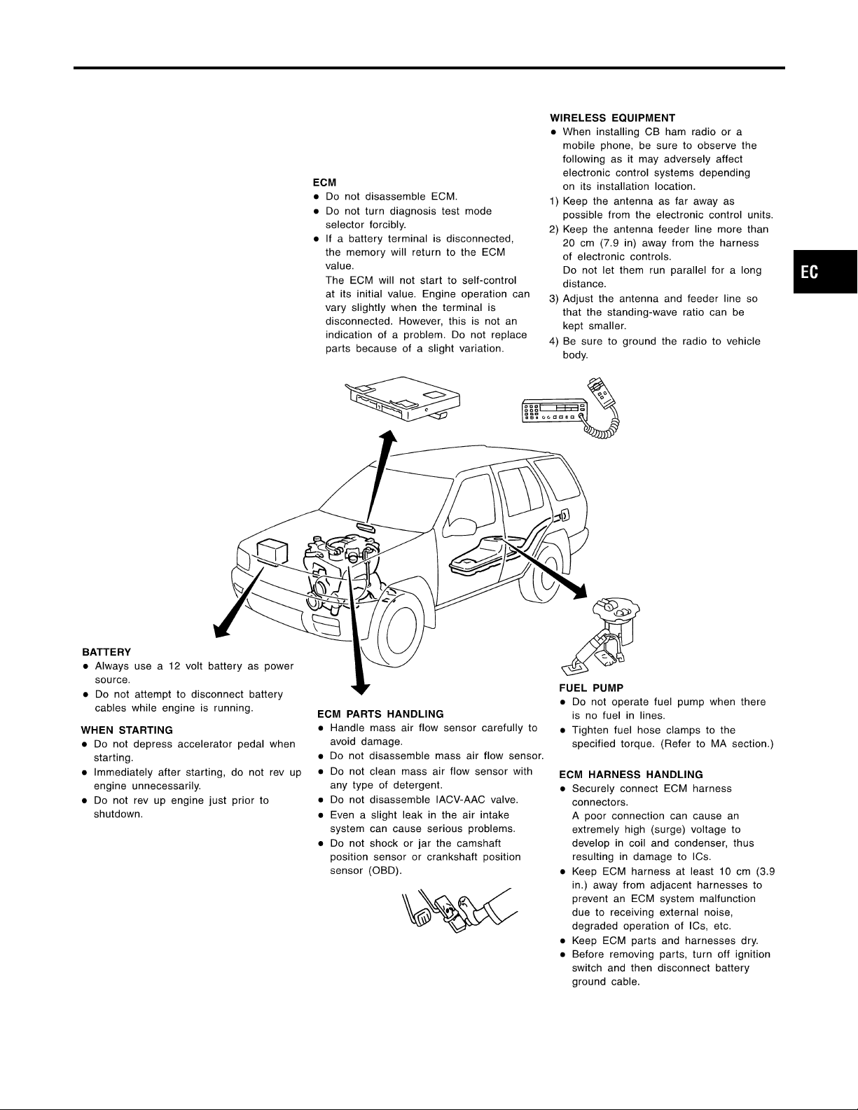
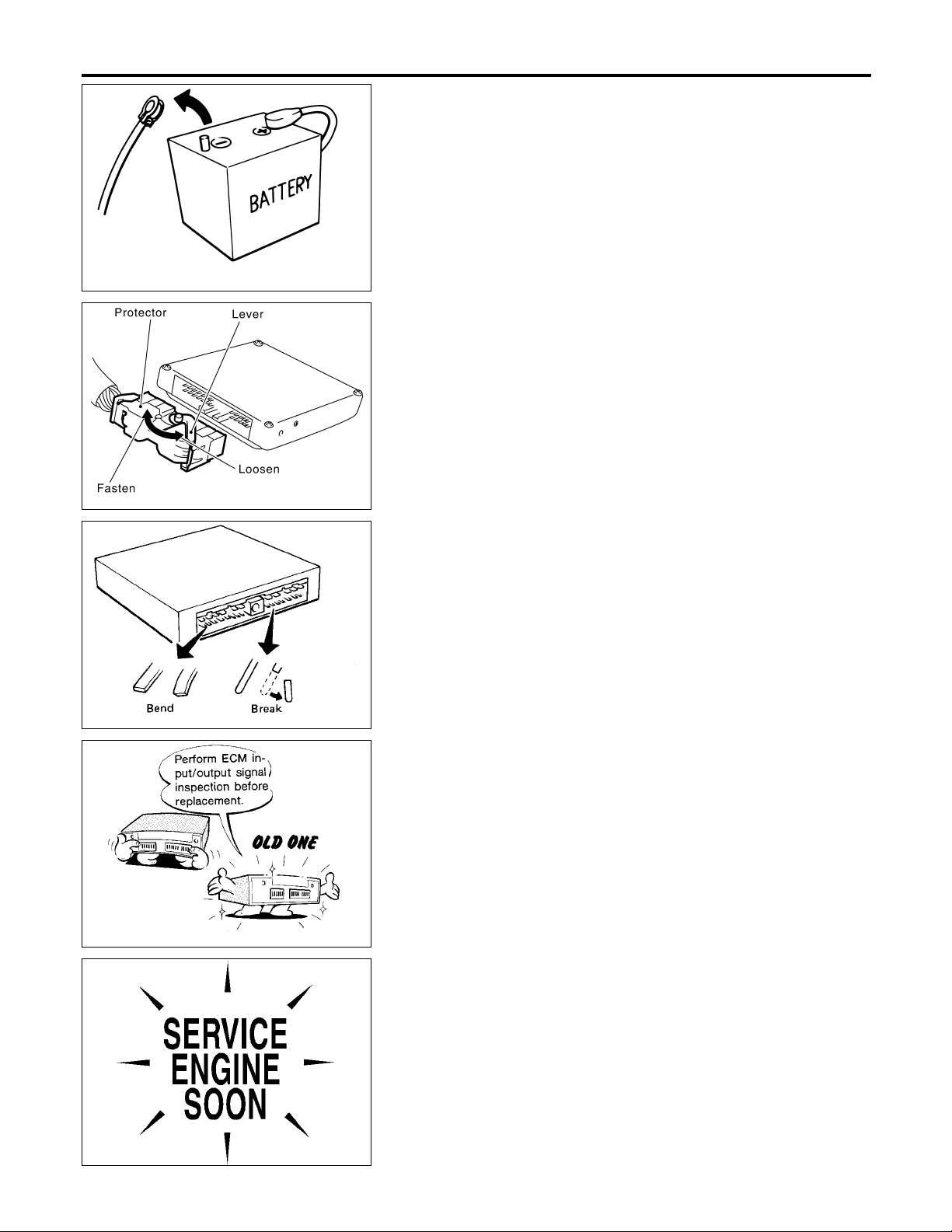
I Before connecting or disconnecting the ECM harness
connector, turn ignition switch OFF and disconnect negative battery terminal. Failure to do so may damage the
ECM because battery voltage is applied to ECM even if
ignition switch is turned off.
I When connecting ECM harness connector, fasten it
securely with a lever as far as it will go as shown at left.
I When connecting or disconnecting pin connectors into or
from ECM, take care not to damage pin terminals (bend or
break).
Make sure that there are not any bends or breaks on ECM
pin terminal, when connecting pin connectors.
SEF291H
MEF040D
SEF217U
I Before replacing ECM, perform “ECM Terminals and Ref-
erence Value” inspection and make sure ECM functions
properly. Refer to EC-127.
I After performing each TROUBLE DIAGNOSIS, perform
“DTC Confirmation Procedure” or “Overall Function
Check”.
The DTC should not be displayed in the “DTC Confirmation Procedure” if the repair is completed. The “Overall
Function Check” should be a good result if the repair is
completed.
EC-16
Page 17
PRECAUTIONS
Precautions (Cont’d)
SEF348N
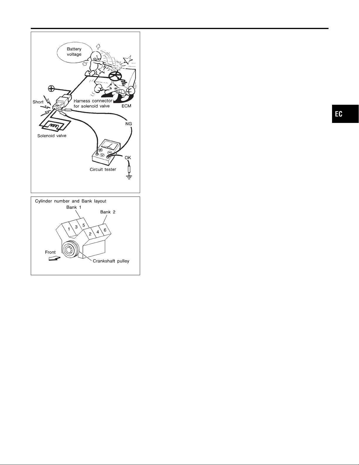
I When measuring ECM signals with a circuit tester, never
allow the two tester probes to contact.
Accidental contact of probes will cause a short circuit and
damage the ECM power transistor.
I Do not use ECM ground terminals when measuring input/
output voltage. Doing so may result in damage to the
ECM’s transistor. Use a ground other than the ECM
terminals, such as the ground.
I Regarding model R50, “-B1” indicates the right bank and
“-B2” indicates the left bank as shown in the figure.
I Bank 1 includes No. 1 cylinder.
GI
MA
EM
LC
FE
CL
MT
AT
TF
SEF099WB
Wiring Diagrams and Trouble Diagnosis
When you read Wiring diagrams, refer to the following:
I GI-11, “HOW TO READ WIRING DIAGRAMS”
I EL-12, “POWER SUPPLY ROUTING” for power distribution circuit
When you perform trouble diagnosis, refer to the following:
I GI-35, “HOW TO FOLLOW TEST GROUPS IN TROUBLE DIAGNOSES”
I GI-24, “HOW TO PERFORM EFFICIENT DIAGNOSIS FOR AN ELECTRICAL INCIDENT”
PD
AX
SU
NAEC0006
BR
ST
RS
BT
HA
SC
EC-17
EL
IDX
Page 18
Special Service Tools
PREPARATION
Special Service Tools
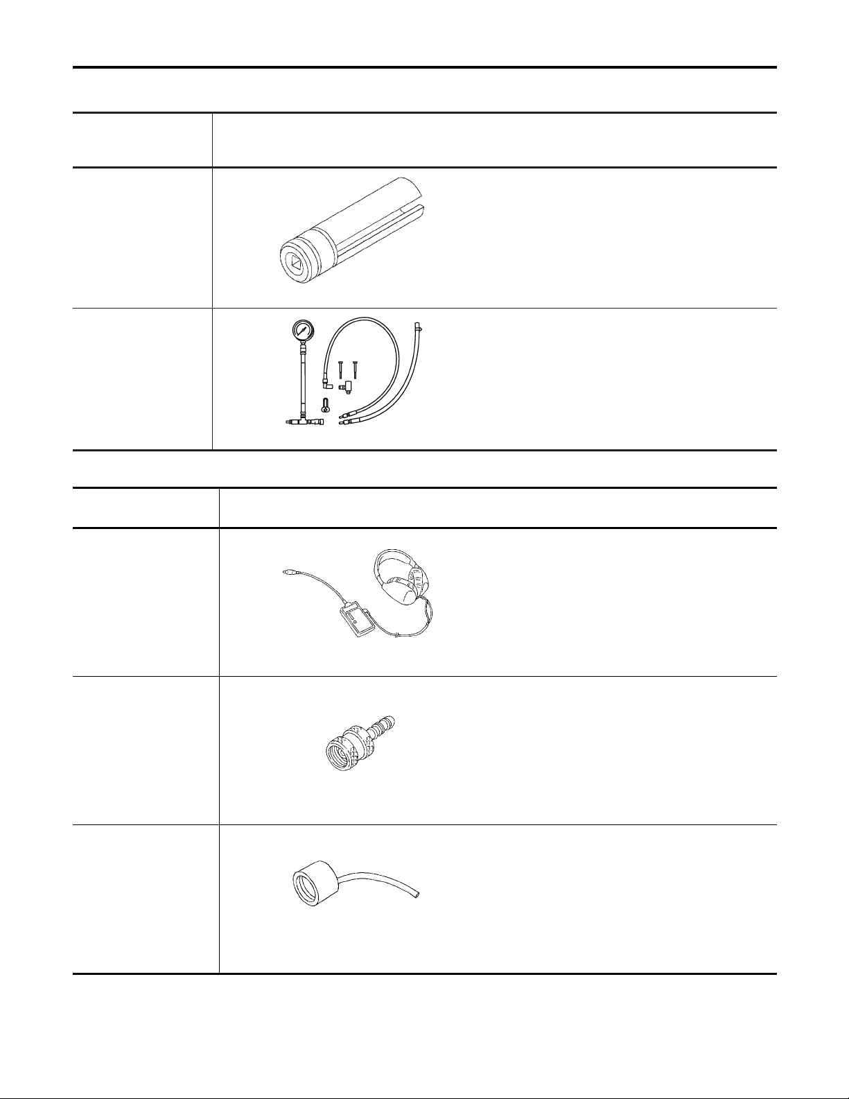
The actual shapes of Kent-Moore tools may differ from those of special service tools illustrated here.
Tool number
(Kent-Moore No.)
Tool name
KV10117100
(J36471-A)
Front heated oxygen
sensor wrench
Rear heated oxygen
sensor wrench
(J44321)
Fuel pressure adapter
and gauge kit
Description
Loosening or tightening front and rear heated oxygen sensors with 22 mm (0.87 in) hexagon nut
NT379
Checking fuel pressure with pressure gauge
SEF326Z
Commercial Service Tools
Tool name
(Kent-Moore No.)
Description
NAEC0007
NAEC0008
Leak detector
(J41416)
EVAP service port
adapter
(J41413-OBD)
Fuel filler cap adapter
Locating the EVAP leak
NT703
Applying positive pressure through EVAP service
port
NT704
Checking fuel tank vacuum relief valve opening
pressure
NT653
EC-18
Page 19
PREPARATION
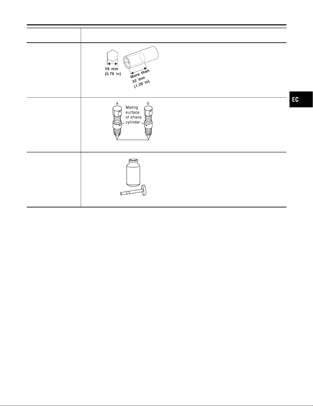
Commercial Service Tools (Cont’d)
Tool name
(Kent-Moore No.)
Socket wrench
Oxygen sensor thread
cleaner
(J-43897-18)
(J-43897-12)
Anti-seize lubricant (Per-
TM
matex
equivalent meeting MIL
specification MIL-A-907)
133AR or
Description
NT705
NT828
Removing and installing engine coolant temperature sensor
Reconditioning the exhaust system threads before
installing a new oxygen sensor. Use with antiseize lubricant shown below.
a: J-43897-18 18 mm diameter with pitch 1.5
mm, for Zirconia Oxygen Sensor
b: J-43897-12 12 mm diameter with pitch 1.25
mm, for Titania Oxygen Sensor
Lubricating oxygen sensor thread cleaning tool
when reconditioning exhaust system threads.
GI
MA
EM
LC
FE
CL
MT
AT
NT779
TF
PD
AX
SU
BR
ST
RS
BT
HA
EC-19
SC
EL
IDX
Page 20
ENGINE AND EMISSION CONTROL OVERALL SYSTEM
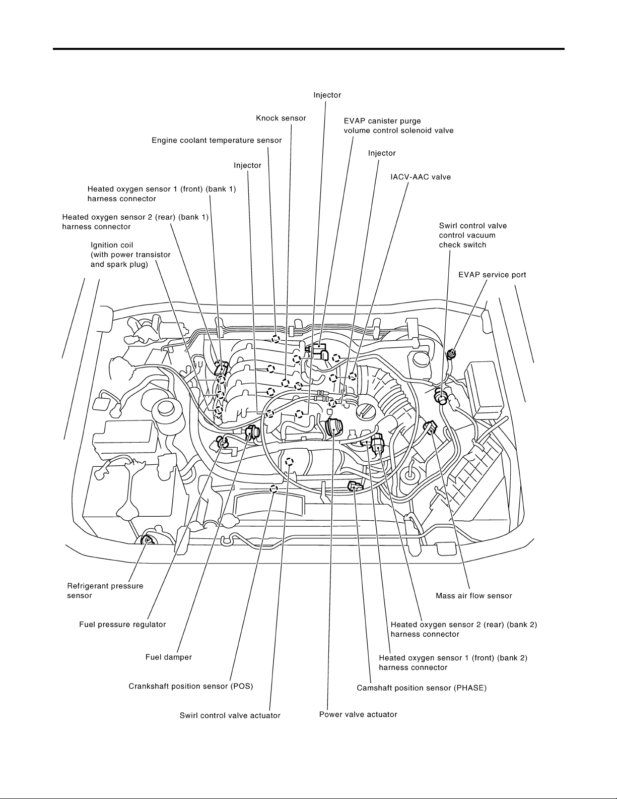
Engine Control Component Parts Location
Engine Control Component Parts Location
NAEC0009
EC-20
SEF952Z
Page 21
ENGINE AND EMISSION CONTROL OVERALL SYSTEM
Engine Control Component Parts Location (Cont’d)
GI
MA
EM
LC
FE
CL
MT
AT
TF
PD
AX
SU
BR
ST
RS
BT
EC-21
HA
SC
EL
SEF034Z
IDX
Page 22
ENGINE AND EMISSION CONTROL OVERALL SYSTEM
Engine Control Component Parts Location (Cont’d)
EC-22
SEF584Z
Page 23
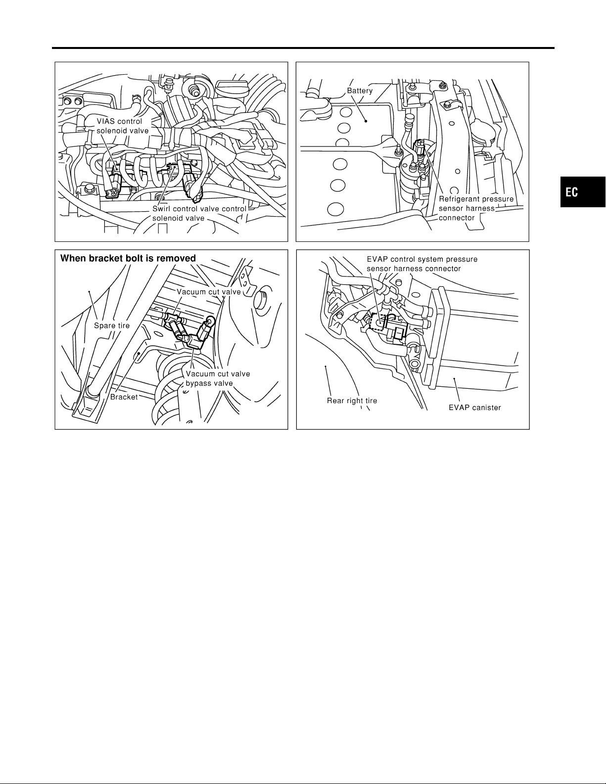
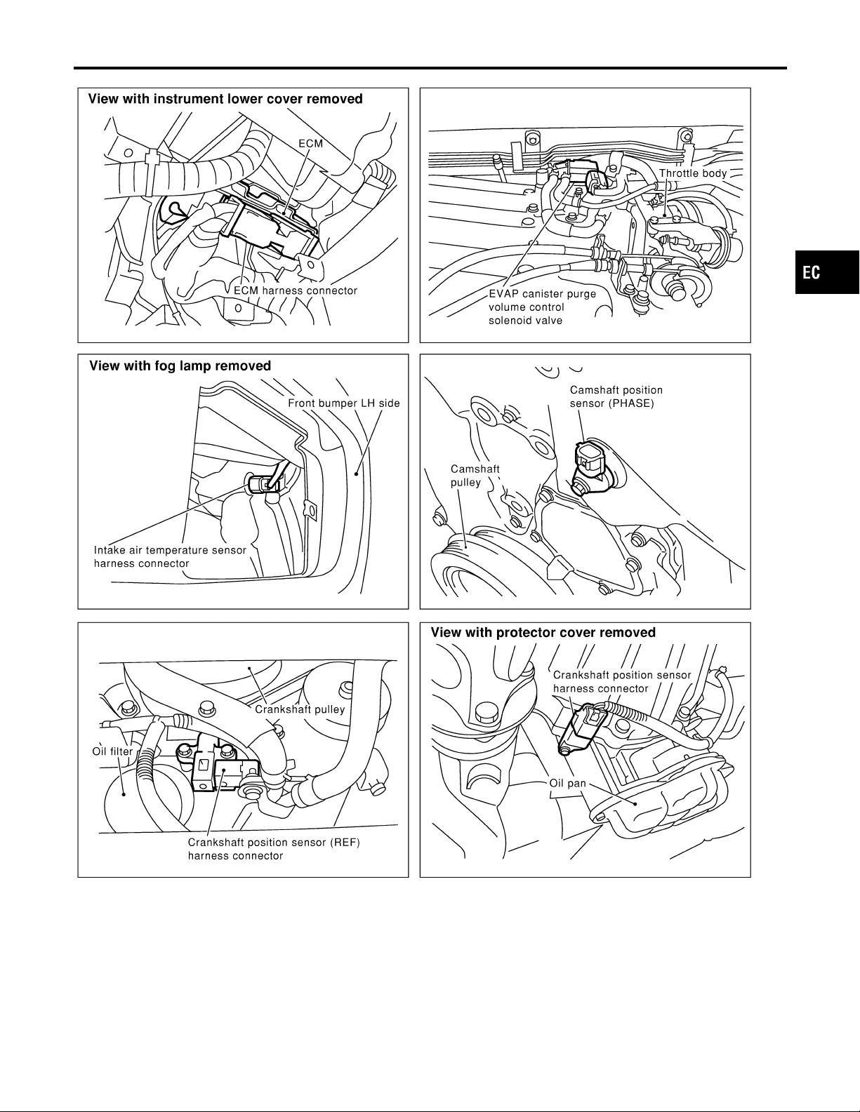
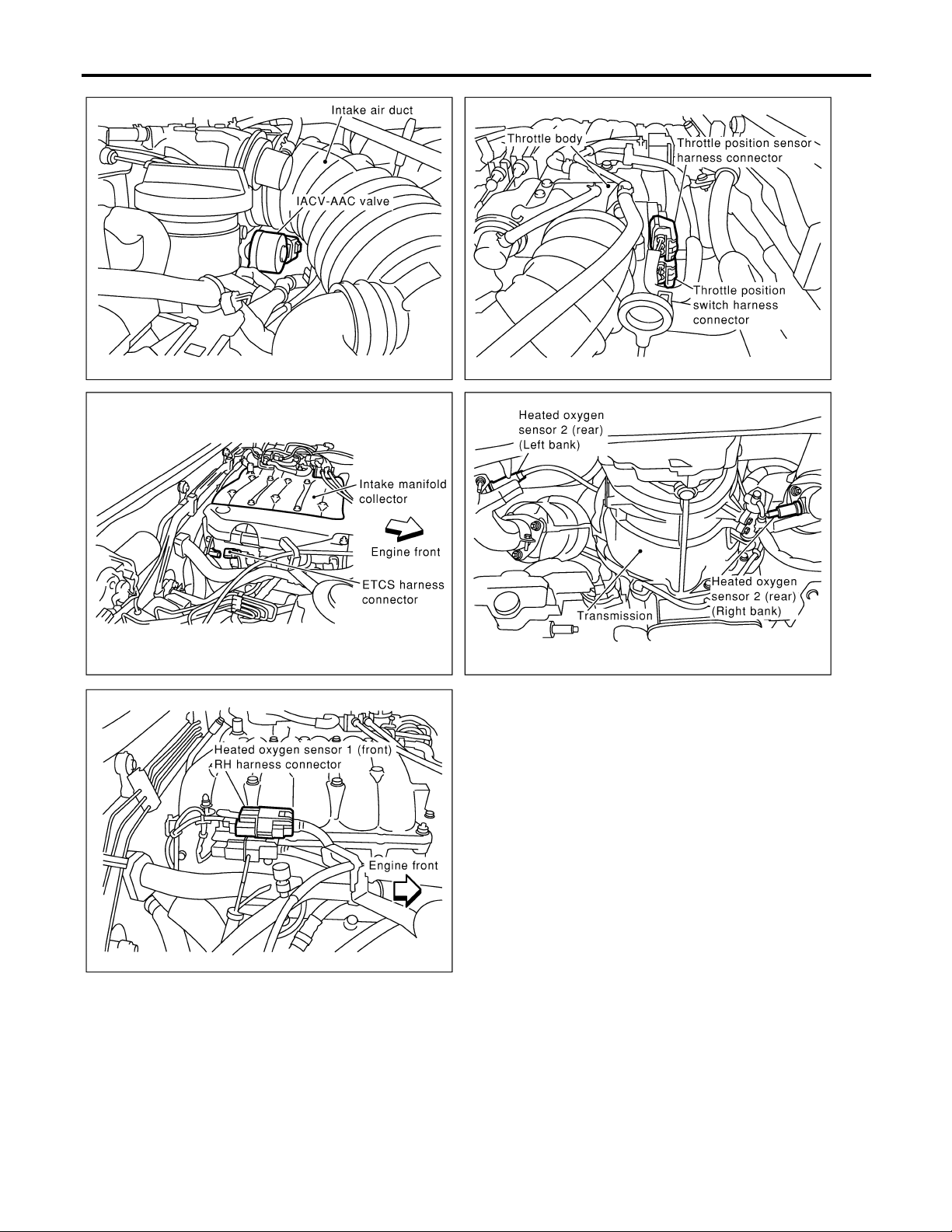
ENGINE AND EMISSION CONTROL OVERALL SYSTEM
Engine Control Component Parts Location (Cont’d)
GI
MA
EM
LC
FE
CL
MT
AT
TF
PD
AX
SU
BR
ST
RS
BT
EC-23
HA
SC
EL
SEF036Z
IDX
Page 24
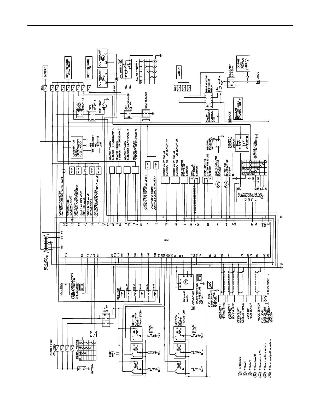
Circuit Diagram
ENGINE AND EMISSION CONTROL OVERALL SYSTEM
Circuit Diagram
MODELS WITH SMART C/U — PREVIOUS
NAEC0010
NAEC0010S01
EC-24
MEC316D
Page 25
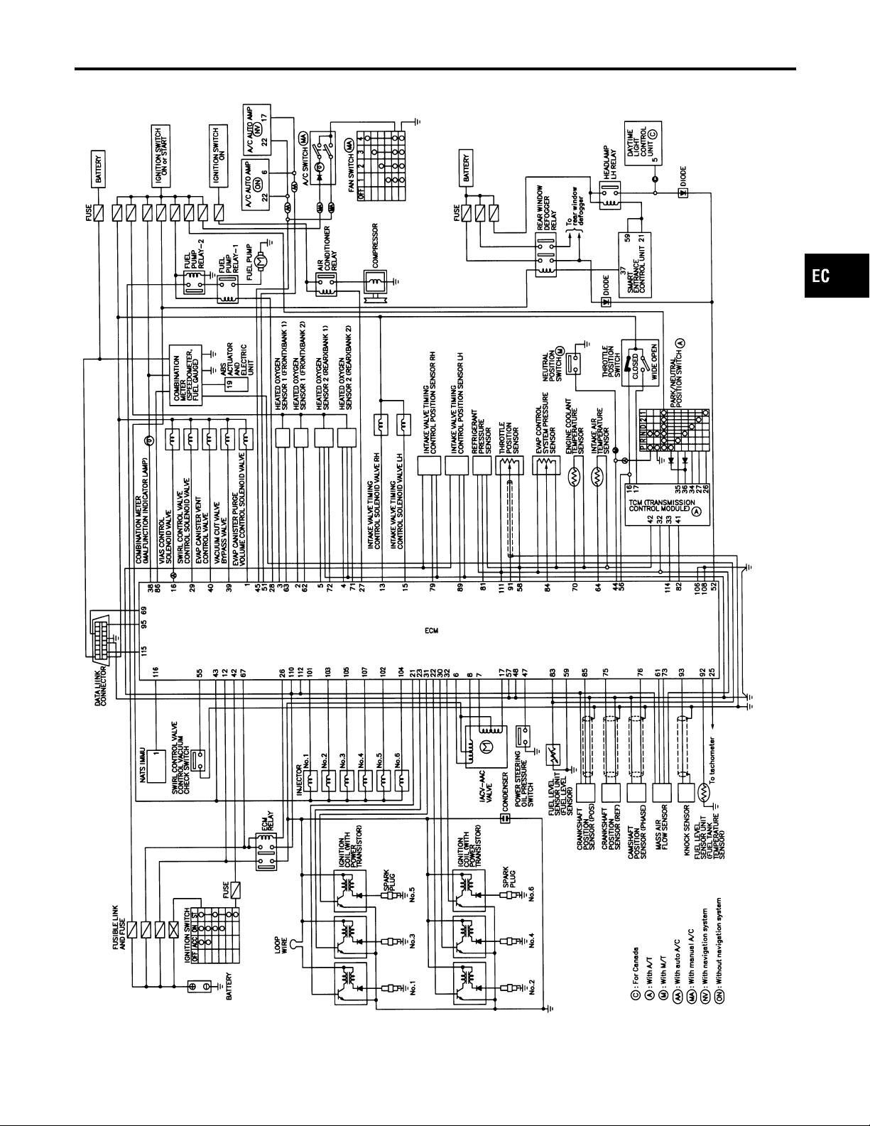
ENGINE AND EMISSION CONTROL OVERALL SYSTEM
Circuit Diagram (Cont’d)
MODELS WITH SMART C/U — NEW
NAEC0010S02
GI
MA
EM
LC
FE
CL
MT
AT
TF
PD
AX
SU
BR
ST
RS
BT
HA
EC-25
SC
EL
MEC391D
IDX
Page 26
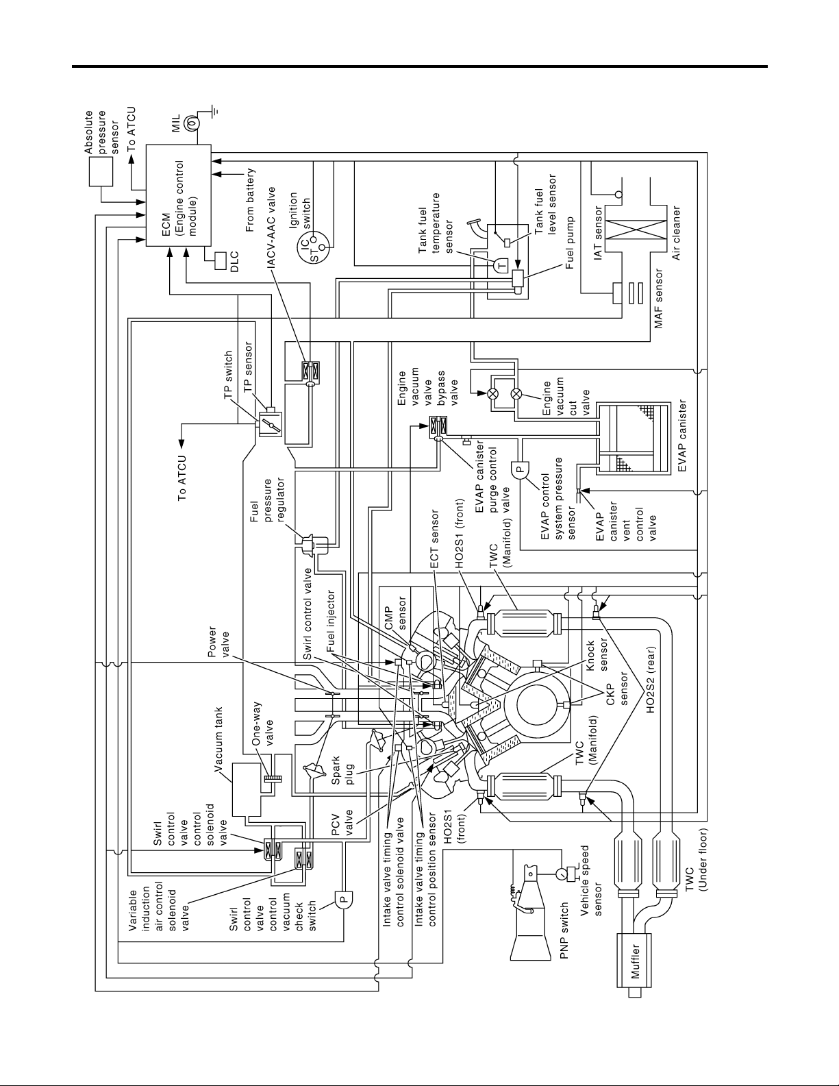
System Diagram
ENGINE AND EMISSION CONTROL OVERALL SYSTEM
System Diagram
NAEC0011
EC-26
SEC306C
Page 27
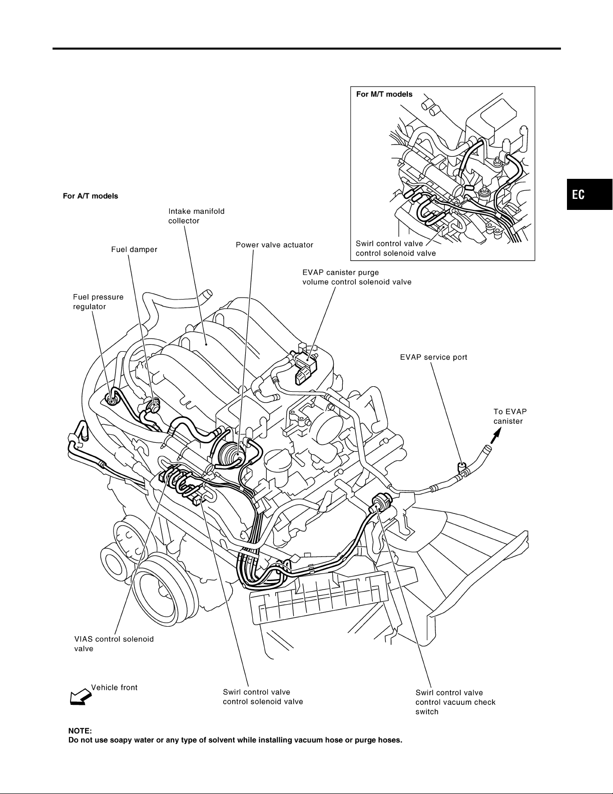
ENGINE AND EMISSION CONTROL OVERALL SYSTEM
Vacuum Hose Drawing
Vacuum Hose Drawing
Refer to “System Diagram”, EC-26 for Vacuum Control System.
NAEC0012
GI
MA
EM
LC
FE
CL
MT
AT
TF
PD
AX
SU
BR
ST
RS
BT
HA
EC-27
SEF953Z
SC
EL
IDX
Page 28

System Chart
ENGINE AND EMISSION CONTROL OVERALL SYSTEM
Input (Sensor) ECM Function Output (Actuator)
I Camshaft position sensor (PHASE)
I Crankshaft position sensor (REF)
I Mass air flow sensor
I Engine coolant temperature sensor
I Heated oxygen sensor 1 (front)
I Ignition switch
I Throttle position sensor
I Closed throttle position switch *3
I Park/neutral position (PNP) switch
I Air conditioner switch
I Knock sensor
I Intake air temperature sensor
I Absolute pressure sensor
I EVAP control system pressure sensor *1
I Battery voltage
I Power steering oil pressure switch
I Vehicle speed sensor
I Fuel tank temperature sensor *1
I Crankshaft position sensor (POS)
I Heated oxygen sensor 2 (rear)*2
I TCM (Transmission control module)
I Refrigerant pressure sensor
I Electrical load
I Fuel level sensor*1
System Chart
Fuel injection & mixture ratio control Injectors
Electronic ignition system Power transistor
Idle air control system IACV-AAC valve
Fuel pump control Fuel pump relay
On board diagnostic system MIL (On the instrument panel)
Swirl control valve control
Power valve control VIAS control solenoid valve
Heated oxygen sensor 1 heater (front) con-
trol
Heated oxygen sensor 2 heater (rear) control
EVAP canister purge flow control
Air conditioning cut control Air conditioner relay
ON BOARD DIAGNOSIS for EVAP system
Swirl control valve control solenoid
valve
Heated oxygen sensor 1 heater
(front)
Heated oxygen sensor 2 heater
(rear)
EVAP canister purge volume control solenoid valve
I EVAP canister vent control valve
I Vacuum cut valve bypass valve
NAEC0013
*1: These sensors are not used to control the engine system. They are used only for the on board diagnosis.
*2: This sensor is not used to control the engine system under normal conditions.
*3: This switch will operate in place of the throttle position sensor to control EVAP parts if the sensor malfunctions.
EC-28
Page 29
ENGINE AND EMISSION BASIC CONTROL SYSTEM DESCRIPTION
Multiport Fuel Injection (MFI) System
Multiport Fuel Injection (MFI) System
DESCRIPTION
Input/Output Signal Chart
Sensor Input Signal to ECM
Crankshaft position sensor (POS) Engine speed (POS signal)
Crankshaft position sensor (REF) Engine speed (REF signal)
Camshaft position sensor (PHASE) Piston position
Mass air flow sensor Amount of intake air
Engine coolant temperature sensor Engine coolant temperature
Heated oxygen sensor 1 (front) Density of oxygen in exhaust gas
Throttle position sensor
Park/neutral position (PNP) switch Gear position
Vehicle speed sensor Vehicle speed
Ignition switch Start signal
Air conditioner switch Air conditioner operation
Knock sensor Engine knocking condition
Throttle position
Throttle valve idle position
ECM func-
tion
Fuel injection & mixture ratio
control
Injectors
Actuator
NAEC0014
NAEC0014S01
GI
MA
EM
LC
FE
CL
MT
AT
Battery Battery voltage
Absolute pressure sensor Ambient air barometric pressure
Power steering oil pressure switch Power steering operation
Heated oxygen sensor 2 (rear)* Density of oxygen in exhaust gas
*: Under normal conditions, this sensor is not for engine control operation.
Basic Multiport Fuel Injection System
NAEC0014S02
The amount of fuel injected from the fuel injector is determined by the ECM. The ECM controls the length of
time the valve remains open (injection pulse duration). The amount of fuel injected is a program value in the
ECM memory. The program value is preset by engine operating conditions. These conditions are determined
by input signals (for engine speed and intake air) from both the crankshaft position sensor and the mass air
flow sensor.
Various Fuel Injection Increase/Decrease Compensation
NAEC0014S03
In addition, the amount of fuel injected is compensated to improve engine performance under various operating conditions as listed below.
<Fuel increase>
I During warm-up
I When starting the engine
I During acceleration
I Hot-engine operation
I When selector lever is changed from “N” to “D”
I High-load, high-speed operation
<Fuel decrease>
I During deceleration
I During high engine speed operation
TF
PD
AX
SU
BR
ST
RS
BT
HA
SC
EL
EC-29
IDX
Page 30
ENGINE AND EMISSION BASIC CONTROL SYSTEM DESCRIPTION
Multiport Fuel Injection (MFI) System (Cont’d)
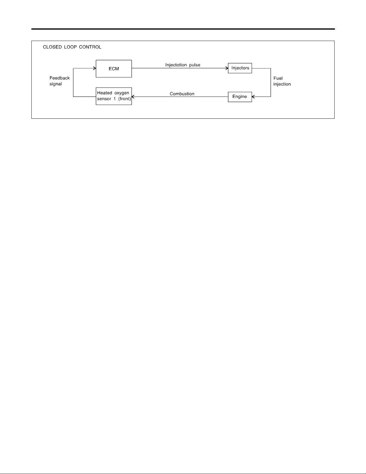
Mixture Ratio Feedback Control (Closed loop control)
NAEC0014S04
SEF336WA
The mixture ratio feedback system provides the best air-fuel mixture ratio for driveability and emission control. The warm-up three way catalyst can then better reduce CO, HC and NOx emissions. This system uses
a heated oxygen sensor 1 (front) in the exhaust manifold to monitor if the engine operation is rich or lean. The
ECM adjusts the injection pulse width according to the sensor voltage signal. For more information about the
heated oxygen sensor 1 (front) , refer to EC-187. This maintains the mixture ratio within the range of stoichiometric (ideal air-fuel mixture).
This stage is referred to as the closed loop control condition.
Heated oxygen sensor 2 (rear) is located downstream of the warm-up three way catalyst. Even if the switching characteristics of the heated oxygen sensor 1 (front) shift, the air-fuel ratio is controlled to stoichiometric
by the signal from the heated oxygen sensor 2 (rear).
Open Loop Control
NAEC0014S05
The open loop system condition refers to when the ECM detects any of the following conditions. Feedback
control stops in order to maintain stabilized fuel combustion.
I Deceleration and acceleration
I High-load, high-speed operation
I Malfunction of heated oxygen sensor 1 (front) or its circuit
I Insufficient activation of heated oxygen sensor 1 (front) at low engine coolant temperature
I High engine coolant temperature
I During warm-up
I After shifting from “N” to “D”
I When starting the engine
Mixture Ratio Self-learning Control
NAEC0014S06
The mixture ratio feedback control system monitors the mixture ratio signal transmitted from the heated oxygen sensor 1 (front). This feedback signal is then sent to the ECM. The ECM controls the basic mixture ratio
as close to the theoretical mixture ratio as possible. However, the basic mixture ratio is not necessarily controlled as originally designed. Both manufacturing differences (i.e., mass air flow sensor hot wire) and characteristic changes during operation (i.e., injector clogging) directly affect mixture ratio.
Accordingly, the difference between the basic and theoretical mixture ratios is monitored in this system. This
is then computed in terms of “injection pulse duration” to automatically compensate for the difference between
the two ratios.
“Fuel trim” refers to the feedback compensation value compared against the basic injection duration. Fuel trim
includes short term fuel trim and long term fuel trim.
“Short term fuel trim” is the short-term fuel compensation used to maintain the mixture ratio at its theoretical
value. The signal from the heated oxygen sensor 1 (front) indicates whether the mixture ratio is RICH or LEAN
compared to the theoretical value. The signal then triggers a reduction in fuel volume if the mixture ratio is
rich, and an increase in fuel volume if it is lean.
“Long term fuel trim” is overall fuel compensation carried out long-term to compensate for continual deviation
of the short term fuel trim from the central value. Such deviation will occur due to individual engine differences,
wear over time and changes in the usage environment.
EC-30
Page 31

ENGINE AND EMISSION BASIC CONTROL SYSTEM DESCRIPTION
Multiport Fuel Injection (MFI) System (Cont’d)
Fuel Injection Timing
NAEC0014S07
SEF179U
Two types of systems are used.
Sequential Multiport Fuel Injection System
NAEC0014S0701
Fuel is injected into each cylinder during each engine cycle according to the firing order. This system is used
when the engine is running.
Simultaneous Multiport Fuel Injection System
NAEC0014S0702
Fuel is injected simultaneously into all six cylinders twice each engine cycle. In other words, pulse signals of
the same width are simultaneously transmitted from the ECM.
The six injectors will then receive the signals two times for each engine cycle.
This system is used when the engine is being started and/or if the fail-safe system (CPU) is operating.
Fuel Shut-off
NAEC0014S08
Fuel to each cylinder is cut off during deceleration or operation of the engine at excessively high speeds.
Electronic Ignition (EI) System
DESCRIPTION
Input/Output Signal Chart
Sensor Input Signal to ECM
Crankshaft position sensor (POS) Engine speed (POS signal)
ECM func-
tion
Actuator
NAEC0015
NAEC0015S01
GI
MA
EM
LC
FE
CL
MT
AT
TF
PD
AX
Crankshaft position sensor (REF) Engine speed (REF signal)
Camshaft position sensor (PHASE) Piston position
Mass air flow sensor Amount of intake air
Engine coolant temperature sensor Engine coolant temperature
Throttle position sensor
Vehicle speed sensor Vehicle speed
Ignition switch Start signal
Knock sensor Engine knocking
Park/neutral position (PNP) switch Gear position
Battery Battery voltage
Throttle position
Throttle valve idle position
Ignition
timing control
SU
BR
ST
Power transistor
RS
BT
HA
SC
EL
IDX
EC-31
Page 32

ENGINE AND EMISSION BASIC CONTROL SYSTEM DESCRIPTION
Electronic Ignition (EI) System (Cont’d)
System Description
SEF742M
NAEC0015S02
The ignition timing is controlled by the ECM to maintain the best air-fuel ratio for every running condition of
the engine. The ignition timing data is stored in the ECM. This data forms the map shown.
The ECM receives information such as the injection pulse width and camshaft position sensor signal. Computing this information, ignition signals are transmitted to the power transistor.
e.g., N: 1,800 rpm, Tp: 1.50 msec
A °BTDC
During the following conditions, the ignition timing is revised by the ECM according to the other data stored
in the ECM.
I At starting
I During warm-up
I At idle
I At low battery voltage
I During acceleration
The knock sensor retard system is designed only for emergencies. The basic ignition timing is programmed
within the anti-knocking zone, if recommended fuel is used under dry conditions. The retard system does not
operate under normal driving conditions. If engine knocking occurs, the knock sensor monitors the condition.
The signal is transmitted to the ECM. The ECM retards the ignition timing to eliminate the knocking condition.
Air Conditioning Cut Control
DESCRIPTION
Input/Output Signal Chart
Sensor Input Signal to ECM ECM function Actuator
Air conditioner switch Air conditioner “ON” signal
Throttle position sensor Throttle valve opening angle
Crankshaft position sensor (POS) Engine speed (POS signal)
Crankshaft position sensor (REF) Engine speed (REF signal)
Engine coolant temperature sensor Engine coolant temperature
Ignition switch Start signal
Vehicle speed sensor Vehicle speed
Refrigerant pressure sensor Refrigerant pressure
Power steering oil pressure switch Power steering operation
System Description
This system improves engine operation when the air conditioner is used.
Under the following conditions, the air conditioner is turned off.
I When the accelerator pedal is fully depressed.
I When cranking the engine.
I At high engine speeds.
Air conditioner
cut control
NAEC0016
NAEC0016S01
Air conditioner relay
NAEC0016S02
EC-32
Page 33

ENGINE AND EMISSION BASIC CONTROL SYSTEM DESCRIPTION
Air Conditioning Cut Control (Cont’d)
I When the engine coolant temperature becomes excessively high.
I When operating power steering during low engine speed or low vehicle speed.
I When engine speed is excessively low.
I When refrigerant pressure is excessively low or high.
Fuel Cut Control (at no load & high engine speed)
DESCRIPTION
Input/Output Signal Chart
Sensor Input Signal to ECM
Vehicle speed sensor Vehicle speed
Park/neutral position (PNP) switch Neutral position
Throttle position sensor Throttle position
Engine coolant temperature sensor Engine coolant temperature
Crankshaft position sensor (POS) Engine speed (POS signal)
Crankshaft position sensor (REF) Engine speed (REF signal)
If the engine speed is above 1,800 rpm with no load (for example, in neutral and engine speed over 1,800
rpm) fuel will be cut off after some time. The exact time when the fuel is cut off varies based on engine speed.
Fuel cut will operate until the engine speed reaches 1,500 rpm, then fuel cut is cancelled.
NOTE:
This function is different from deceleration control listed under “Multiport Fuel Injection (MFI) System”, EC-29.
ECM func-
tion
Fuel cut
control
Actuator
Injectors
NAEC0017
NAEC0017S01
GI
MA
EM
LC
FE
CL
MT
AT
TF
Evaporative Emission System
DESCRIPTION
The evaporative emission system is used to reduce hydrocarbons emitted into the atmosphere from the fuel
system. This reduction of hydrocarbons is accomplished by activated charcoals in the EVAP canister.
The fuel vapor in the sealed fuel tank is led into the EVAP canister which contains activated carbon and the
vapor is stored there when the engine is not operating or when refueling to the fuel tank.
The vapor in the EVAP canister is purged by the air through the purge line to the intake manifold when the
engine is operating. EVAP canister purge volume control solenoid valve is controlled by ECM. When the engine
NAEC0018
SEF927U
PD
AX
SU
BR
ST
RS
BT
HA
SC
EL
IDX
EC-33
Page 34

ENGINE AND EMISSION BASIC CONTROL SYSTEM DESCRIPTION
Evaporative Emission System (Cont’d)
operates, the flow rate of vapor controlled by EVAP canister purge volume control solenoid valve is proportionally regulated as the air flow increases.
EVAP canister purge volume control solenoid valve also shuts off the vapor purge line during decelerating and
idling.
SEF428T
SEF231SB
SEF427N
INSPECTION
EVAP Canister
NAEC0019
NAEC0019S01
Check EVAP canister as follows:
1. Pinch the fresh air hose.
2. Blow air into port A and check that it flows freely out of port B.
Tightening Torque
NAEC0019S02
Tighten EVAP canister as shown in the figure.
Make sure new O-ring is installed properly between EVAP canister and EVAP canister vent control valve.
Fuel Tank Vacuum Relief Valve (Built into fuel filler cap)
NAEC0019S03
1. Wipe clean valve housing.
2. Check valve opening pressure and vacuum.
Pressure:
15.3 - 20.0 kPa (0.156 - 0.204 kg/cm
2
, 2.22 - 2.90 psi)
Vacuum:
−6.0 to −3.3 kPa (−0.061 to −0.034 kg/cm
2
, −0.87 to
−0.48 psi)
3. If out of specification, replace fuel filler cap as an assembly.
CAUTION:
Use only a genuine fuel filler cap as a replacement. If an incorrect fuel filler cap is used, the MIL may come on.
SEF943S
EC-34
Page 35

ENGINE AND EMISSION BASIC CONTROL SYSTEM DESCRIPTION
Evaporative Emission System (Cont’d)
SEF462UA
SEF200U
PEF838U
Vacuum Cut Valve and Vacuum Cut Valve Bypass Valve
Refer to EC-583.
NAEC0019S04
Evaporative Emission (EVAP) Canister Purge Volume
Control Solenoid Valve
Refer to EC-362.
Fuel Tank Temperature Sensor
Refer to EC-304.
Evap Service Port
Positive pressure is delivered to the EVAP system through the
EVAP service port. If fuel vapor leakage in the EVAP system
occurs, use a leak detector to locate the leak.
How to Detect Fuel Vapor Leakage
CAUTION:
I Never use compressed air or a high pressure pump.
I Do not exceed 4.12 kPa (0.042 kg/cm
in EVAP system.
NOTE:
I Do not start engine.
I Improper installation of EVAP service port adapter to the EVAP
service port may cause a leak.
With CONSULT-II
1) Attach the EVAP service port adapter securely to the EVAP
service port.
2) Also attach the pressure pump and hose to the EVAP service
port adapter.
3) Turn ignition switch “ON”.
4) Select the “EVAP SYSTEM CLOSE” of “WORK SUPPORT
MODE” with CONSULT-II.
5) Touch “START”. A bar graph (Pressure indicating display) will
appear on the screen.
6) Apply positive pressure to the EVAP system until the pressure
indicator reaches the middle of the bar graph.
7) Remove EVAP service port adapter and hose with pressure
pump.
8) Locatethe leak using a leak detector. Refer to “EVAPORATIVE
EMISSION LINE DRAWING”, EC-37.
2
, 0.6 psi) of pressure
NAEC0019S05
NAEC0019S06
NAEC0019S07
NAEC0019S08
NAEC0019S0801
GI
MA
EM
LC
FE
CL
MT
AT
TF
PD
AX
SU
BR
ST
RS
BT
HA
PEF917U
SC
EL
IDX
EC-35
Page 36

ENGINE AND EMISSION BASIC CONTROL SYSTEM DESCRIPTION
Evaporative Emission System (Cont’d)
SEF462UA
SEF598U
Without CONSULT-II
NAEC0019S0802
1) Attach the EVAP service port adapter securely to the EVAP
service port.
2) Also attach the pressure pump with pressure gauge to the
EVAP service port adapter.
3) Apply battery voltage to between the terminals of both EVAP
canister vent control valve and vacuum cut valve bypass valve
to make a closed EVAP system.
4) To locate the leak, deliver positive pressure to the EVAP system until pressure gauge points reach 1.38 to 2.76 kPa (0.014
to 0.028 kg/cm
2
, 0.2 to 0.4 psi).
5) Remove EVAP service port adapter and hose with pressure
pump.
6) Locatethe leak using a leak detector. Refer to “EVAPORATIVE
EMISSION LINE DRAWING”, EC-37.
EC-36
Page 37

ENGINE AND EMISSION BASIC CONTROL SYSTEM DESCRIPTION
Evaporative Emission System (Cont’d)
EVAPORATIVE EMISSION LINE DRAWING
NAEC0020
GI
MA
EM
LC
FE
CL
MT
AT
TF
PD
AX
SU
BR
ST
RS
BT
HA
EC-37
SC
EL
SEF954Z
IDX
Page 38

ENGINE AND EMISSION BASIC CONTROL SYSTEM DESCRIPTION
Evaporative Emission System (Cont’d)
EC-38
SEF870T
Page 39

ENGINE AND EMISSION BASIC CONTROL SYSTEM DESCRIPTION
Positive Crankcase Ventilation
SEF372Q
SEF559A
Positive Crankcase Ventilation
DESCRIPTION
This system returns blow-by gas to the intake manifold.
The positive crankcase ventilation (PCV) valve is provided to conduct crankcase blow-by gas to the intake manifold.
During partial throttle operation of the engine, the intake manifold
sucks the blow-by gas through the PCV valve.
Normally, the capacity of the valve is sufficient to handle any
blow-by and a small amount of ventilating air.
The ventilating air is then drawn from the air inlet tubes into the
crankcase. In this process the air passes through the hose connecting air inlet tubes to rocker cover.
Under full-throttle condition, the manifold vacuum is insufficient to
draw the blow-by flow through the valve. The flow goes through the
hose connection in the reverse direction.
On vehicles with an excessively high blow-by, the valve does not
meet the requirement. This is because some of the flow will go
through the hose connection to the air inlet tubes under all
conditions.
INSPECTION
PCV (Positive Crankcase Ventilation) Valve
With engine running at idle, remove PCV valve ventilation hose
from PCV valve; if the valve is working properly, a hissing noise will
be heard as air passes through it and a strong vacuum should be
felt immediately when a finger is placed over valve inlet.
NAEC0021
NAEC0022
NAEC0022S01
GI
MA
EM
LC
FE
CL
MT
AT
TF
PD
SEC137A
ET277
PCV Valve Ventilation Hose
1. Check hoses and hose connections for leaks.
2. Disconnect all hoses and clean with compressed air. If any
hose cannot be freed of obstructions, replace.
NAEC0022S02
AX
SU
BR
ST
RS
BT
HA
SC
EL
EC-39
IDX
Page 40

Fuel Pressure Release
BASIC SERVICE PROCEDURE
SEF941Y
SEF214Y
Fuel Pressure Release
NAEC0023
Before disconnecting fuel line, release fuel pressure from fuel
line to eliminate danger.
WITH CONSULT-II
NAEC0023S01
1. Turn ignition switch “ON”.
2. Perform “FUEL PRESSURE RELEASE” in “WORK SUPPORT” mode with CONSULT-II.
3. Start engine.
4. After engine stalls, crank it two or three times to release all fuel
pressure.
5. Turn ignition switch “OFF”.
WITHOUT CONSULT-II
NAEC0023S02
1. Remove fuel pump fuse located in fuse box.
2. Start engine.
3. After engine stalls, crank it two or three times to release all fuel
pressure.
4. Turn ignition switch “OFF”.
5. Reinstall fuel pump fuse after servicing fuel system.
SEF933Y
SEF327Z
Fuel Pressure Check
NAEC0024
I When reconnecting fuel line, always use new clamps.
I Make sure that clamp screw does not contact adjacent
parts.
I Use a torque driver to tighten clamps.
I Use Pressure Gauge to check fuel pressure.
I Do not perform fuel pressure check with system operat-
ing. Fuel pressure gauge may indicate false readings.
1. Release fuel pressure to zero.
2. Disconnect fuel tube joint between fuel damper and injector
tube and set fuel pressure check adapter (J44321).
EC-40
Page 41

BASIC SERVICE PROCEDURE
Fuel Pressure Check (Cont’d)
SEF328Z
3. Install pressure gauge to the fuel pressure check adapter as
shown in the figure.
4. Start engine and check for fuel leakage.
5. Read the indication of fuel pressure gauge.
At idling:
With vacuum hose connected
Approximately 235 kPa (2.4 kg/cm
With vacuum hose disconnected
Approximately 294 kPa (3.0 kg/cm
If results are unsatisfactory, perform Fuel Pressure Regulator
Check.
Fuel Pressure Regulator Check
1. Stop engine and disconnect fuel pressure regulator vacuum
hose from vacuum gallery.
2. Plug vacuum gallery with a blind cap.
3. Connect variable vacuum source to fuel pressure regulator.
2
, 34 psi)
2
, 43 psi)
NAEC0025
GI
MA
EM
LC
FE
CL
MT
AT
TF
PD
SEF329Z
SEF718BA
4. Start engine and read indication of fuel pressure gauge as
vacuum is changed.
Fuel pressure should decrease as vacuum increases. If results
are unsatisfactory, replace fuel pressure regulator.
AX
SU
BR
ST
RS
BT
HA
SC
EL
EC-41
IDX
Page 42

Injector
BASIC SERVICE PROCEDURE
Injector
REMOVAL AND INSTALLATION
1. Release fuel pressure to zero.
2. Remove intake manifold collector. Refer to EM-20, “TIMING
CHAIN”.
3. Remove fuel tube assemblies in numerical sequence as
shown in the figure at left.
4. Expand and remove clips securing fuel injectors.
5. Extract fuel injectors straight from fuel tubes.
SEF937Y
SEF703X
I Be careful not to damage injector nozzles during removal.
I Do not bump or drop fuel injectors.
6. Carefully install O-rings, including the one used with the pressure regulator.
I Lubricate O-rings with a smear of engine oil.
I Be careful not to damage O-rings with service tools, fin-
ger nails or clips. Do not expand or twist O-rings.
I Discard old clips; replace with new ones.
7. Position clips in grooves on fuel injectors.
I Make sure that protrusions of fuel injectors are aligned
with cutouts of clips after installation.
NAEC0026
SEF938Y
8. Align protrusions of fuel tubes with those of fuel injectors.
Insert fuel injectors straight into fuel tubes.
9. After properly inserting fuel injectors, check to make sure that
fuel tube protrusions are engaged with those of fuel injectors,
and that flanges of fuel tubes are engaged with clips.
EC-42
Page 43

BASIC SERVICE PROCEDURE
Injector (Cont’d)
SEF939Y
SEF058Y
10. Tighten fuel tube assembly mounting nuts in numerical
sequence (indicated in the figure at left) and in two stages.
: Tightening torque N·m (kg-m, ft-lb)
1st stage:
9.3 - 10.8 (1.0 - 1.1, 6.9 - 7.9)
2nd stage:
20.6 - 26.5 (2.1 - 2.7, 16 - 19)
11. Install all parts removed in reverse order of removal.
CAUTION:
After properly connecting fuel tube assembly to injector and
fuel hose, check connection for fuel leakage.
How to Check Idle Speed and Ignition Timing
IDLE SPEED
I Using CONSULT-II
Check idle speed in “DATA MONITOR” mode with CONSULT-II.
IGNITION TIMING
Any of following two methods may be used.
I Method A
a) Attach timing light to loop wire as shown.
b) Check ignition timing.
NAEC0607
NAEC0607S01
NAEC0607S02
GI
MA
EM
LC
FE
CL
MT
AT
TF
PD
SEF940Y
SEF942Y
I Method B
a) Remove No. 1 ignition coil.
AX
SU
BR
ST
RS
BT
HA
SC
EL
EC-43
IDX
Page 44

BASIC SERVICE PROCEDURE
How to Check Idle Speed and Ignition Timing (Cont’d)
b) Connect No. 1 ignition coil and No. 1 spark plug with suitable
c) Check ignition timing.
SEF943Y
high-tension wire as shown, and attach timing light clamp to
this wire.
SEF572X
SEF311Q
Idle Speed/Ignition Timing/Idle Mixture Ratio Adjustment
PREPARATION
1) Make sure that the following parts are in good order.
I Battery
I Ignition system
I Engine oil and coolant levels
I Fuses
I ECM harness connector
I Vacuum hoses
EC-44
NAEC0028
NAEC0028S01
Page 45

BASIC SERVICE PROCEDURE
Idle Speed/Ignition Timing/Idle Mixture Ratio Adjustment (Cont’d)
I Air intake system
(Oil filler cap, oil level gauge, etc.)
I Fuel pressure
I Engine compression
I Throttle valve
I Evaporative emission system
2) On air conditioner equipped models, checks should be carried out while the air conditioner is “OFF”.
3) On automatic transmission equipped models, when checking idle rpm, ignition timing and mixture ratio,
checks should be carried out while shift lever is in “N” position.
4) When measuring “CO” percentage, insert probe more than 40 cm (15.7 in) into tail pipe.
5) Turn off headlamps, heater blower, rear defogger.
6) Keep front wheels pointed straight ahead.
7) Make the check after the cooling fan has stopped.
GI
MA
EM
LC
FE
CL
MT
AT
TF
PD
AX
SU
BR
ST
RS
BT
HA
EC-45
SC
EL
IDX
Page 46

BASIC SERVICE PROCEDURE
Idle Speed/Ignition Timing/Idle Mixture Ratio Adjustment (Cont’d)
Overall Inspection Sequence
NAEC0028S0101
EC-46
SEC141C
Page 47

BASIC SERVICE PROCEDURE
Idle Speed/Ignition Timing/Idle Mixture Ratio Adjustment (Cont’d)
INSPECTION PROCEDURE
1 INSPECTION START
1. Visually check the following:
I Air cleaner clogging
I Hoses and ducts for leaks
I Electrical connectors
I Gasket
I Throttle valve and throttle position sensor operation
2. Start engine and warm it up until engine coolant temperature indicator points to the middle of gauge.
Ensure engine stays below 1,000 rpm.
3. Open engine hood and run engine at about 2,000 rpm for about 2 minutes under no-load.
=NAEC0028S02
SEF976U
GI
MA
EM
LC
FE
CL
MT
AT
4. Make sure that no DTC is displayed with CONSULT-II or GST.
OK or NG
OK © GO TO 3.
NG © GO TO 2.
2 REPAIR OR REPLACE
Repair or replace components as necessary according to corresponding “Diagnostic Procedure”.
© GO TO 3.
TF
PD
SEF977U
AX
SU
BR
ST
RS
BT
HA
EC-47
SC
EL
IDX
Page 48

BASIC SERVICE PROCEDURE
Idle Speed/Ignition Timing/Idle Mixture Ratio Adjustment (Cont’d)
3 CHECK TARGET IDLE SPEED
With CONSULT-II
1. Start engine and warm it up to normal operating temperature.
2. Select “ENG SPEED” in “DATA MONITOR” mode with CONSULT-II.
3. Check idle speed.
M/T: 750±50 rpm
A/T: 750±50 rpm (in “P” or “N” position)
Without CONSULT-II
1. Start engine and warm it up to normal operating temperature.
2. Check idle speed.
M/T: 750±50 rpm
A/T: 750±50 rpm (in “P” or “N” position)
OK or NG
OK © GO TO 12.
NG © GO TO 4.
4 PERFORM IDLE AIR VOLUME LEARNING
Refer to “Idle Air Volume Learning”, EC-59.
Which is the result CMPLT or INCMP?
CMPLT or INCMP
CMPLT © GO TO 5.
INCMP © 1. Follow the construction of “Idle Air Volume Leaning”.
2. GO TO 4.
5 CHECK TARGET IDLE SPEED AGAIN
With CONSULT-II
1. Start engine and warm it up to normal operating temperature.
2. Select “ENG SPEED” in “DATA MONITOR” mode with CONSULT-II.
3. Check idle speed.
M/T: 750±50 rpm
A/T: 750±50 rpm (in “P” or “N” position)
Without CONSULT-II
1. Start engine and warm it up to normal operating temperature.
2. Check idle speed.
M/T: 750±50 rpm
A/T: 750±50 rpm (in “P” or “N” position)
OK or NG
OK © GO TO 10.
NG © GO TO 6.
6 REPLACE IACV-AAC VALVE
Replace IACV-AAC valve.
© GO TO 7.
EC-48
Page 49

BASIC SERVICE PROCEDURE
Idle Speed/Ignition Timing/Idle Mixture Ratio Adjustment (Cont’d)
7 PERFORM IDLE AIR VOLUME LEARNING
Refer to “Idle Air Volume Learning”, EC-59.
Which is the result CMPLT or INCMP?
CMPLT or INCMP
CMPLT © GO TO 8.
INCMP © 1. Follow the construction of “Idle Air Volume Learning”.
2. GO TO 4.
8 CHECK TARGET IDLE SPEED AGAIN
With CONSULT-II
1. Start engine and warm it up to normal operating temperature.
2. Select “ENG SPEED” in “DATA MONITOR” mode with CONSULT-II.
3. Check idle speed.
M/T: 750±50 rpm
A/T: 750±50 rpm (in “P” or “N” position)
Without CONSULT-II
1. Start engine and warm it up to normal operating temperature.
2. Check idle speed.
M/T: 750±50 rpm
A/T: 750±50 rpm (in “P” or “N” position)
OK or NG
OK © GO TO 10.
NG © GO TO 9.
GI
MA
EM
LC
FE
CL
MT
AT
TF
9 CHECK ECM FUNCTION
1. Substitute another known-good ECM to check ECM function. (ECM may be the cause of a problem, but this is rarely
the case.)
2. Perform initialization of NVIS (NATS) system and registration of NVIS (NATS) ignition key IDs. Refer to “NVIS (NISSAN
VEHICLE IMMOBILIZER SYSTEM — NATS)”, EC-76.
© GO TO 4.
10 CHECK IGNITION TIMING
1. Start engine and warm it up to normal operating temperature.
2. Check ignition timing at idle using a timing light.
SEF572X
Ignition timing:
M/T: 15°±5° BTDC
A/T: 15°±5° BTDC (in “P” or “N” position)
OK or NG
OK © GO TO 18.
NG © GO TO 11.
PD
AX
SU
BR
ST
RS
BT
HA
SC
EL
IDX
EC-49
Page 50

BASIC SERVICE PROCEDURE
Idle Speed/Ignition Timing/Idle Mixture Ratio Adjustment (Cont’d)
11 CHECK TIMING CHAIN INSTALLATION
Check timing chain installation. Refer to EM-29, “Installation”.
OK or NG
OK © GO TO 9.
NG © 1. Repair the timing chain installation.
2. GO TO 4.
12 CHECK IGNITION TIMING
1. Start engine and let it idle.
2. Check ignition timing at idle using a timing light.
Ignition timing:
M/T: 15°±5° BTDC
A/T: 15°±5° BTDC (in “P” or “N” position)
OK or NG
OK © GO TO 18.
NG © GO TO 13.
13 PERFORM IDLE AIR VOLUME LEARNING
Refer to “Idle Air Volume Learning”, EC-59.
Which is the result CMPLT or INCMP?
CMPLT or INCMP
CMPLT © GO TO 14.
INCMP © 1. Follow the construction of “Idle Air volume Learning”.
2. GO TO 13.
SEF572X
EC-50
Page 51

BASIC SERVICE PROCEDURE
Idle Speed/Ignition Timing/Idle Mixture Ratio Adjustment (Cont’d)
14 CHECK TARGET IDLE SPEED AGAIN
With CONSULT-II
1. Start engine and warm it up to normal operating temperature.
2. Select “ENG SPEED” in “DATA MONITOR” mode with CONSULT-II.
3. Check idle speed.
M/T: 750±50 rpm
A/T: 750±50 rpm (in “P” or “N” position)
Without CONSULT-II
1. Start engine and warm it up to normal operating temperature.
2. Check idle speed.
M/T: 750±50 rpm
A/T: 750±50 rpm (in “P” or “N” position)
OK or NG
OK © GO TO 16.
NG © GO TO 15.
15 CHECK ECM FUNCTION
1. Substitute another known-good ECM to check ECM function.
(ECM may be the cause of a problem, but this is rarely the case.)
2. Perform initialization of NVIS (NATS) system and registration of NVIS (NATS) ignition key IDs. Refer to “NVIS (NISSAN
VEHICLE IMMOBILIZER SYSTEM — NATS)”, EC-76.
© GO TO 13.
16 CHECK IGNITION TIMING AGAIN
Check ignition timing again. Refer to Test No. 12.
OK or NG
OK © GO TO 18.
NG © GO TO 17.
GI
MA
EM
LC
FE
CL
MT
AT
TF
PD
AX
17 CHECK TIMING CHAIN INSTALLATION
Check timing chain installation. Refer to EM-29, “Installation”.
OK or NG
OK © GO TO 15.
NG © 1. Repair the timing chain installation.
2. GO TO 13.
18 ERASE UNNECESSARY DTC
After this inspection, unnecessary DTC No. might be displayed.
Erase the stored memory in ECM and TCM (Transmission control module).
Refer to “HOW TO ERASE EMISSION-RELATED DIAGNOSTIC INFORMATION”, EC-74 and AT-35 , “HOW TO ERASE
DTC”.
With CONSULT-II © GO TO 19.
Without CONSULT-II © GO TO 20.
SU
BR
ST
RS
BT
HA
SC
EL
IDX
EC-51
Page 52

BASIC SERVICE PROCEDURE
Idle Speed/Ignition Timing/Idle Mixture Ratio Adjustment (Cont’d)
19 CHECK HEATED OXYGEN SENSOR 1 (FRONT) (BANK 2) SIGNAL
With CONSULT-II
1. Run engine at about 2,000 rpm for about 2 minutes under no-load.
2. See “HO2S1 MNTR (B2)” in “DATA MONITOR” mode.
3. Running engine at 2,000 rpm under no-load (engine is warmed up to normal operating temperature.), check that the
monitor fluctuates between “LEAN” and “RICH” more than 5 times during 10 seconds.
OK or NG
OK © GO TO 23.
NG (Monitor does not
fluctuate.)
NG (Monitor fluctuates
less than 5 times.)
© GO TO 28.
© GO TO 21.
SEF945Y
20 CHECK HEATED OXYGEN SENSOR 1 (FRONT) (BANK 2) SIGNAL
Without CONSULT-II
1. Run engine at about 2,000 rpm for about 2 minutes under no-load.
2. Set voltmeter probe between ECM terminal 62 and ground.
3. Make sure that the voltage fluctuates between 0 - 0.3V and 0.6 - 1.0V more than 5 times during 10 seconds at 2,000
rpm.
1 time: 0 - 0.3V → 0.6 - 1.0V → 0 - 0.3V
2 times: 0 - 0.3V → 0.6 - 1.0V → 0 - 0.3V → 0.6 - 1.0V → 0 - 0.3V
OK or NG
OK © GO TO 23.
NG (Voltage does not
fluctuate.)
NG (Voltage fluctuates
less than 5 times.)
© GO TO 28.
© GO TO 21.
EC-52
Page 53

BASIC SERVICE PROCEDURE
Idle Speed/Ignition Timing/Idle Mixture Ratio Adjustment (Cont’d)
21 CHECK HEATED OXYGEN SENSOR 1 (FRONT) (BANK 2) SIGNAL
With CONSULT-II
1. Stop engine.
2. Replace heated oxygen sensor 1 (front) (bank 2).
3. Start engine and warm it up to normal operating temperature.
4. Run engine at approx. 2,000 rpm for approx. 2 minutes under no-load.
5. See “HO2S1 MNTR (B2)” in “DATA MONITOR” mode.
6. Running engine at 2,000 rpm under no-load (engine is warmed up to normal operating temperature.), check that the
monitor fluctuates between “LEAN” and “RICH” more than 5 times during 10 seconds.
1 time: RICH → LEAN → RICH
2 times: RICH → LEAN → RICH → LEAN → RICH
Without CONSULT-II
1. Stop engine.
2. Replace heated oxygen sensor 1 (front) (bank 2).
3. Start engine and warm it up to normal operating temperature.
4. Run engine at approx. 2,000 rpm for approx. 2 minutes under no-load.
5. Set voltmeter probe between ECM terminal 62 and ground.
6. Make sure that the voltage fluctuates between 0 - 0.3V and 0.6 - 1.0V more than 5 times during 10 seconds at 2,000
rpm.
1 time: 0 - 0.3V → 0.6 - 1.0V → 0 - 0.3V
2 times: 0 - 0.3V → 0.6 - 1.0V → 0 - 0.3V → 0.6 - 1.0V → 0 - 0.3V
OK or NG
OK (With CONSULT-II) © GO TO 23.
OK (Without CONSULT-
II)
NG © GO TO 22.
© GO TO 24.
GI
MA
EM
LC
FE
CL
MT
AT
TF
22 DETECT MALFUNCTIONING PART
Check the following.
1. Check fuel pressure regulator. Refer to EC-41.
2. Check mass air flow sensor and its circuit. Refer to EC-150.
3. Check injector and its circuit. Refer to EC-609.
Clean or replace if necessary.
4. Check engine coolant temperature sensor and its circuit. Refer to EC-182.
5. Check ECM function by substituting another known-good ECM.
(ECM may be the cause of a problem, but this is rarely the case.)
© GO TO 3.
PD
AX
SU
BR
ST
RS
BT
HA
SC
EC-53
EL
IDX
Page 54

BASIC SERVICE PROCEDURE
Idle Speed/Ignition Timing/Idle Mixture Ratio Adjustment (Cont’d)
23 CHECK HEATED OXYGEN SENSOR 1 (FRONT) (BANK 1) SIGNAL
With CONSULT-II
1. See “HO2S1 MNTR (B1)” in “DATA MONITOR” mode.
2. Maintaining engine at 2,000 rpm under no-load (engine is warmed up to normal operating temperature.), check that the
monitor fluctuates between “LEAN” and “RICH” more than 5 times during 10 seconds.
SEF945Y
OK or NG
OK © INSPECTION END
NG (Monitor does not
fluctuate.)
NG (Monitor fluctuates
less than 5 times.)
© GO TO 27.
© GO TO 25.
24 CHECK HEATED OXYGEN SENSOR 1 (FRONT) (BANK 1) SIGNAL
Without CONSULT-II
1. Set voltmeter probe between ECM terminal 63 and ground.
2. Make sure that the voltage fluctuates between 0 - 0.3V and 0.6 - 1.0V more than 5 times during 10 seconds at 2,000
rpm.
1 time: 0 - 0.3V → 0.6 - 1.0V → 0 - 0.3V
2 times: 0 - 0.3V → 0.6 - 1.0V → 0 - 0.3V → 0.6 - 1.0V → 0 - 0.3V
OK or NG
OK © INSPECTION END
NG (Voltage does not
fluctuate.)
NG (Voltage fluctuates
less than 5 times.)
© GO TO 27.
© GO TO 25.
EC-54
Page 55

BASIC SERVICE PROCEDURE
Idle Speed/Ignition Timing/Idle Mixture Ratio Adjustment (Cont’d)
25 CHECK HEATED OXYGEN SENSOR 1 (FRONT) (BANK 1) SIGNAL
With CONSULT-II
1. Stop engine.
2. Replace heated oxygen sensor 1 (front) (bank 1).
3. Start engine and warm it up to normal operating temperature.
4. Run engine at approx. 2,000 rpm for approx. 2 minutes under no-load.
5. See “HO2S1 MNTR (B1)” in “DATA MONITOR” mode.
6. Maintaining engine at 2,000 rpm under no-load (engine is warmed up to normal operating temperature.), check that the
monitor fluctuates between “LEAN” and “RICH” more than 5 times during 10 seconds.
1 time: RICH → LEAN → RICH
2 times: RICH → LEAN → RICH → LEAN → RICH
Without CONSULT-II
1. Stop engine.
2. Replace heated oxygen sensor 1 (front) (bank 1).
3. Start engine and warm it up to normal operating temperature.
4. Run engine at approx. 2,000 rpm for approx. 2 minutes under no-load.
5. Set voltmeter probe between ECM terminal 63 and ground.
6. Make sure that the voltage fluctuates between 0 - 0.3V and 0.6 - 1.0V more than 5 times during 10 seconds at 2,000
rpm.
1 time: 0 - 0.3V → 0.6 - 1.0V → 0 - 0.3V
2 times: 0 - 0.3V → 0.6 - 1.0V → 0 - 0.3V → 0.6 - 1.0V → 0 - 0.3V
OK or NG
OK © INSPECTION END
NG © GO TO 26.
GI
MA
EM
LC
FE
CL
MT
AT
26 DETECT MALFUNCTIONING PART
Check the following.
I Check fuel pressure regulator. Refer to EC-41.
I Check mass air flow sensor and its circuit. Refer to EC-150.
I Check injector and its circuit. Refer to EC-609.
Clean or replace if necessary.
I Check engine coolant temperature sensor and its circuit. Refer to EC-182.
I Check ECM function by substituting another known-good ECM.
(ECM may be the cause of a problem, but this is rarely the case.)
© GO TO 3.
27 CHECK HEATED OXYGEN SENSOR 1 (FRONT) (BANK 1) HARNESS
1. Turn off engine and disconnect battery ground cable.
2. Disconnect ECM harness connector.
3. Disconnect heated oxygen sensor 1 (front) (bank 1) harness connector.
4. Check harness continuity between ECM terminal 63 and heated oxygen sensor 1 (front) (bank 1) harness connector
terminal 1.
Refer to Wiring Diagram, EC-191.
Continuity should exist.
OK or NG
OK © GO TO 30.
NG © GO TO 29.
TF
PD
AX
SU
BR
ST
RS
BT
HA
EC-55
SC
EL
IDX
Page 56

BASIC SERVICE PROCEDURE
Idle Speed/Ignition Timing/Idle Mixture Ratio Adjustment (Cont’d)
28 CHECK HEATED OXYGEN SENSOR 1 (FRONT) (BANK 2) HARNESS
1. Turn off engine and disconnect battery ground cable.
2. Disconnect ECM harness connector.
3. Disconnect heated oxygen sensor 1 (front) (bank 2) harness connector.
4. Check harness continuity between ECM terminal 62 and front heated oxygen sensor LH harness connector terminal 1.
Refer to Wiring Diagram, EC-192.
Continuity should exist.
OK or NG
OK © GO TO 30.
NG © GO TO 29.
29 REPAIR OR REPLACE
Repair or replace harness between ECM and heated oxygen sensor 1 (front).
© GO TO 3.
30 PREPARATION FOR “CO” % CHECK
With CONSULT-II
1. Reconnect ECM harness connector.
2. Turn ignition switch “ON”.
3. Select “ENG COOLANT TEMP” in “ACTIVE TEST” mode.
4. Set “ENG COOLANT TEMP” to 5°C (41°F) by touching “DOWN” and “Qd”.
Without CONSULT-II
1. Disconnect ECM harness connector.
2. Disconnect engine coolant temperature sensor harness connector.
3. Connect a resistor (4.4 kΩ) between terminals of engine coolant temperature sensor harness connector.
© GO TO 31.
SEF172Y
SEF982UA
EC-56
Page 57

BASIC SERVICE PROCEDURE
Idle Speed/Ignition Timing/Idle Mixture Ratio Adjustment (Cont’d)
31 CHECK “CO” %
With CONSULT-II
1. Start engine and warm it up until engine coolant temperature indicator points to the middle of gauge.
2. Rev engine (2,000 to 3,000 rpm) two or three times under no-load, then run engine at idle speed.
3. Check “CO” %.
Idle CO: 1.0 - 9.5%
Without CONSULT-II
1. Start engine and warm it up until engine coolant temperature indicator points to the middle of gauge.
SEF976U
SEF978U
GI
MA
EM
LC
FE
CL
MT
AT
TF
PD
2. Rev engine (2,000 to 3,000 rpm) two or three times under no-load, then run engine at idle speed.
3. Check “CO” %.
4. After checking CO%,
a. Disconnect the resistor from terminals of engine coolant temperature sensor.
b. Connect engine coolant temperature sensor harness connector to engine coolant temperature sensor.
OK or NG
OK © GO TO 32.
NG © GO TO 33.
SEF976U
SEF978U
AX
SU
BR
ST
RS
BT
HA
SC
EL
IDX
EC-57
Page 58

BASIC SERVICE PROCEDURE
Idle Speed/Ignition Timing/Idle Mixture Ratio Adjustment (Cont’d)
32 CHECK HEATED OXYGEN SENSOR 1 (FRONT) (BANK 1)/(BANK 2) SIGNAL
With CONSULT-II
1. Stop engine.
2. Replace heated oxygen sensor 1 (front) (bank 1)/(bank 2).
3. Start engine and warm it up to normal operating temperature.
4. Run engine at approx. 2,000 rpm for approx. 2 minutes under no-load.
5. See “HO2S1 MNTR (B1)/(B2)” in “DATA MONITOR” mode.
6. Maintaining engine at 2,000 rpm under no-load (engine is warmed up to normal operating temperature.), check that the
monitor fluctuates between “LEAN” and “RICH” more than 5 times during 10 seconds.
1 time: RICH → LEAN → RICH
2 times: RICH → LEAN → RICH → LEAN → RICH
Without CONSULT-II
1. Stop engine.
2. Replace heated oxygen sensor 1 (front) (bank 1)/(bank 2).
3. Start engine and warm it up to normal operating temperature.
4. Run engine at approx. 2,000 rpm for approx. 2 minutes under no-load.
5. Set voltmeter probe between ECM terminal 63 or 62 and ground.
6. Make sure that voltage fluctuates between 0 - 0.3V and 0.6 - 1.0V more than 5 times during 10 seconds at 2,000 rpm.
1 time: 0 - 0.3V → 0.6 - 1.0V → 0 - 0.3V
2 times: 0 - 0.3V → 0.6 - 1.0V → 0 - 0.3V → 0.6 - 1.0V → 0 - 0.3V
OK or NG
OK © GO TO 3.
NG © GO TO 33.
33 DETECT MALFUNCTIONING PART
Check the following.
I Connect heated oxygen sensor 1 (front) harness connectors to heated oxygen sensors 1 (front).
I Check fuel pressure regulator. Refer to EC-41.
I Check mass air flow sensor and its circuit. Refer to EC-150.
I Check injector and its circuit. Refer to EC-609.
Clean or replace if necessary.
I Check engine coolant temperature sensor and its circuit. Refer to EC-182.
I Check ECM function by substituting another known-good ECM.
(ECM may be the cause of a problem, but this is rarely the case.)
© GO TO 3.
EC-58
Page 59

BASIC SERVICE PROCEDURE
Idle Air Volume Learning
SEF452Y
SEF454Y
SEF455Y
Idle Air Volume Learning
DESCRIPTION
“Idle Air Volume Learning” is an operation to learn the idle air volume that keeps each engine within the specific range. It must be
performed under any of the following conditions:
I Each time IACV-AAC valve, throttle body or ECM is replaced.
I Idle speed or ignition timing is out of specification.
PRE-CONDITIONING
Before performing “Idle Air Volume Learning”, make sure that all of
the following conditions are satisfied.
Learning will be cancelled if any of the following conditions are
missed for even a moment.
I Battery voltage: More than 12.9V (At idle)
I Engine coolant temperature: 70 - 99°C (158 - 210°F)
I PNP switch: ON
I Electric load switch: OFF
(Air conditioner, headlamp, rear window defogger)
On vehicles equipped with daytime running light systems, if
the parking brake is applied before the engine is started the
headlamp will not illuminate.
I Cooling fan motor: Not operating
I Steering wheel: Neutral (Straight-ahead position)
I Vehicle speed: Stopped
I Transmission: Warmed-up
For A/T models with CONSULT-II, drive vehicle until “FLUID
TEMP SE” in “DATA MONITOR” mode of “A/T” system indicates less than 0.9V.
For A/T models without CONSULT-II and M/T models, drive
vehicle for 10 minutes.
OPERATION PROCEDURE
With CONSULT-II
1. Turn ignition switch “ON” and wait at least 1 second.
2. Turn ignition switch “OFF” and wait at least 10 seconds.
3. Start engine and warm it up to normal operating temperature.
4. Check that all items listed under the topic “PRE-CONDITIONING” (previously mentioned) are in good order.
5. Turn ignition switch “OFF” and wait at least 10 seconds.
6. Start the engine and let it idle for at least 30 seconds.
7. Select “IDLE AIR VOL LEARN” in “WORK SUPPORT” mode.
8. Touch “START” and wait 20 seconds.
9. Make sure that “CMPLT” is displayed on CONSULT-II screen.
If “INCMP” is displayed, “Idle Air Volume Learning” will not be
carried out successfully. In this case, find the cause of the
problem by referring to the NOTE below.
10. Rev up the engine two or three times. Make sure that idle
speed and ignition timing are within specifications.
NAEC0642
NAEC0642S01
NAEC0642S02
NAEC0642S03
NAEC0642S0301
GI
MA
EM
LC
FE
CL
MT
AT
TF
PD
AX
SU
BR
ST
RS
BT
HA
ITEM SPECIFICATION
Idle speed M/T: 750±50 rpm
A/T: 750±50 rpm (in “P” or “N” position)
Ignition timing M/T: 15°±5° BTDC
A/T: 15°±5° BTDC (in “P” or “N” position)
EC-59
SC
EL
IDX
Page 60

Idle Air Volume Learning (Cont’d)
BASIC SERVICE PROCEDURE
SEF944Y
Without CONSULT-II
NAEC0642S0302
1. Turn ignition switch “ON” and wait at least 1 second.
2. Turn ignition switch “OFF” and wait at least 10 seconds.
3. Start engine and warm it up to normal operating temperature.
4. Check that all items listed under the topic “PRE-CONDITIONING” (previously mentioned) are in good order.
5. Turn ignition switch “OFF” and wait at least 10 seconds.
6. Start the engine and let it idle for at least 30 seconds.
7. Disconnect throttle position sensor harness connector (brown),
then reconnect it within 5 seconds.
8. Wait 20 seconds.
9. Make sure that idle speed is within specifications. If not, the
result will be incomplete. In this case, find the cause of the
problem by referring to the NOTE below.
10. Rev up the engine two or three times. Make sure that idle
speed and ignition timing are within specifications.
ITEM SPECIFICATION
Idle speed M/T: 750±50 rpm
A/T: 750±50 rpm (in “P” or “N” position)
Ignition timing M/T: 15°±5° BTDC
A/T: 15°±5° BTDC (in “P” or “N” position)
NOTE:
If idle air volume learning cannot be performed successfully,
proceed as follows:
1) Check that throttle valve is fully closed.
2) Check PCV valve operation.
3) Check that downstream of throttle valve is free from air
leakage.
4) Adjust closed throttle position switch and reset memory.
(Refer to Basic Inspection, EC-103.)
5) When the above four items check out OK, engine component parts and their installation condition are questionable. Check and eliminate the cause of the problem. It is
useful to perform “TROUBLE DIAGNOSIS — SPECIFICATION VALVE”, EC-136.
6) If any of the following conditions occur after the engine
has started, eliminate the cause of the problem and perform “Idle air volume learning” all over again:
I Engine stalls.
I Erroneous idle.
I Blown fuses related to the IACV-AAC valve system.
EC-60
Page 61

ON BOARD DIAGNOSTIC SYSTEM DESCRIPTION
Introduction
Introduction
NAEC0029
The ECM has an on board diagnostic system, which detects malfunctions related to engine sensors or actuators. The ECM also records various emission-related diagnostic information including:
Emission-related diagnostic information SAE Mode
Diagnostic Trouble Code (DTC) Mode 3 of SAE J1979
Freeze Frame data Mode 2 of SAE J1979
System Readiness Test (SRT) code Mode 1 of SAE J1979
1st Trip Diagnostic Trouble Code (1st Trip DTC) Mode 7 of SAE J1979
1st Trip Freeze Frame data
Test values and Test limits Mode 6 of SAE J1979
The above information can be checked using procedures listed in the table below.
X: Applicable —: Not applicable
DTC 1st trip DTC
CONSULT-II X X X X X —
GST X X*1 X — X X
*1: 1st trip DTCs for self-diagnoses concerning SRT items cannot be shown on the GST display.
Freeze Frame
data
1st trip Freeze
Frame data
SRT code Test value
The malfunction indicator lamp (MIL) on the instrument panel lights up when the same malfunction is detected
in two consecutive trips (Two trip detection logic), or when the ECM enters fail-safe mode. (Refer to EC-117.)
Two Trip Detection Logic
NAEC0030
When a malfunction is detected for the first time, 1st trip DTC and 1st trip Freeze Frame data are stored in
the ECM memory. The MIL will not light up at this stage. <1st trip>
If the same malfunction is detected again during the next drive, the DTC and Freeze Frame data are stored
in the ECM memory, and the MIL lights up. The MIL lights up at the same time when the DTC is stored. <2nd
trip> The “trip” in the “Two Trip Detection Logic” means a driving mode in which self-diagnosis is performed
during vehicle operation. Specific on board diagnostic items will cause the ECM to light up or blink the MIL,
and store DTC and Freeze Frame data, even in the 1st trip, as shown below.
X: Applicable —: Not Exit
MIL DTC 1st trip DTC
GI
MA
EM
LC
FE
CL
MT
AT
TF
PD
AX
SU
Items
Misfire (Possible three way catalyst damage) — DTC: P0300 P0306 (0701, 0605 — 0608) is
being detected
Misfire (Possible three way catalyst damage) — DTC: P0300 P0306 (0701, 0605 — 0608) is
being detected
Closed loop control
— DTC: P1148 (0307), P1168
(0308)
Fail-safe items (Refer to EC-117.) — X — — X*1 — X*1 —
Except above — — — X — X X —
*1: Except “ECM”
1st trip 2nd trip
Blinking
X—————X—
——X ——X——
—X——X—X—
Lighting
up
Blinking
Lighting
up
1st trip
displaying
2nd trip
displaying
1st trip
displaying
displaying
EC-61
2nd trip
BR
ST
RS
BT
HA
SC
EL
IDX
Page 62

ON BOARD DIAGNOSTIC SYSTEM DESCRIPTION
Emission-related Diagnostic Information
Emission-related Diagnostic Information
DTC AND 1ST TRIP DTC
NAEC0031
NAEC0031S01
The 1st trip DTC (whose number is the same as the DTC number) is displayed for the latest self-diagnostic
result obtained. If the ECM memory was cleared previously, and the 1st trip DTC did not reoccur, the 1st trip
DTC will not be displayed.
If a malfunction is detected during the 1st trip, the 1st trip DTC is stored in the ECM memory. The MIL will not
light up (two trip detection logic). If the same malfunction is not detected in the 2nd trip (meeting the required
driving pattern), the 1st trip DTC is cleared from the ECM memory. If the same malfunction is detected in the
2nd trip, both the 1st trip DTC and DTC are stored in the ECM memory and the MIL lights up. In other words,
the DTC is stored in the ECM memory and the MIL lights up when the same malfunction occurs in two consecutive trips. If a 1st trip DTC is stored and a non-diagnostic operation is performed between the 1st and
2nd trips, only the 1st trip DTC will continue to be stored. For malfunctions that blink or light up the MIL during the 1st trip, the DTC and 1st trip DTC are stored in the ECM memory.
Procedures for clearing the DTC and the 1st trip DTC from the ECM memory are described in “HOW TO
ERASE EMISSION-RELATED DIAGNOSTIC INFORMATION”, EC-74.
For malfunctions in which 1st trip DTCs are displayed, refer to EC-71. These items are required by legal
regulations to continuously monitor the system/component. In addition, the items monitored non-continuously
are also displayed on CONSULT-II.
1st trip DTC is specified in Mode 7 of SAE J1979. 1st trip DTC detection occurs without lighting up the MIL
and therefore does not warn the driver of a problem. However, 1st trip DTC detection will not prevent the
vehicle from being tested, for example during Inspection/Maintenance (I/M) tests.
When a 1st trip DTC is detected, check, print out or write down and erase (1st trip) DTC and Freeze Frame
data as specified in “Work Flow” procedure Step II, refer to EC-101. Then perform “DTC Confirmation Procedure” or “Overall Function Check” to try to duplicate the problem. If the malfunction is duplicated, the item
requires repair.
How to Read DTC and 1st Trip DTC
NAEC0031S0101
DTC and 1st trip DTC can be read by the following methods.
With CONSULT-II
With GST
CONSULT-II or GST (Generic Scan Tool) Examples: P0340, P1320, P0705, P0750, etc.
These DTCs are prescribed by SAE J2012.
(CONSULT-II also displays the malfunctioning component or system.)
I 1st trip DTC No. is the same as DTC No.
I Output of a DTC indicates a malfunction. However, GST does not indicate whether the malfunction
is still occurring or has occurred in the past and has returned to normal. CONSULT-II can identify
malfunction status as shown below. Therefore, using CONSULT-II (if available) is recommended.
A sample of CONSULT-II display for DTC and 1st trip DTC is shown below. DTC or 1st trip DTC of a malfunction is displayed in SELF-DIAGNOSTIC RESULTS mode of CONSULT-II. Time data indicates how many times
the vehicle was driven after the last detection of a DTC.
If the DTC is being detected currently, the time data will be “0”.
If a 1st trip DTC is stored in the ECM, the time data will be “[1t]”.
SEF992X
FREEZE FRAME DATA AND 1ST TRIP FREEZE FRAME DATA
NAEC0031S02
The ECM records the driving conditions such as fuel system status, calculated load value, engine coolant
temperature, short term fuel trim, long term fuel trim, engine speed, vehicle speed and absolute pressure at
the moment a malfunction is detected.
Data which are stored in the ECM memory, along with the 1st trip DTC, are called 1st trip freeze frame data.
EC-62
Page 63

ON BOARD DIAGNOSTIC SYSTEM DESCRIPTION
Emission-related Diagnostic Information (Cont’d)
The data, stored together with the DTC data, are called freeze frame data and displayed on CONSULT-II or
GST. The 1st trip freeze frame data can only be displayed on the CONSULT-II screen, not on the GST. For
details, see EC-87.
Only one set of freeze frame data (either 1st trip freeze frame data or freeze frame data) can be stored in the
ECM. 1st trip freeze frame data is stored in the ECM memory along with the 1st trip DTC. There is no priority for 1st trip freeze frame data and it is updated each time a different 1st trip DTC is detected. However, once
freeze frame data (2nd trip detection/MIL on) is stored in the ECM memory, 1st trip freeze frame data is no
longer stored. Remember, only one set of freeze frame data can be stored in the ECM. The ECM has the following priorities to update the data.
Priority Items
1
2 Except the above items (Includes A/T related items)
3 1st trip freeze frame data
For example, the EGR malfunction (Priority: 2) was detected and the freeze frame data was stored in the 2nd
trip. After that when the misfire (Priority: 1) is detected in another trip, the freeze frame data will be updated
from the EGR malfunction to the misfire. The 1st trip freeze frame data is updated each time a different malfunction is detected. There is no priority for 1st trip freeze frame data. However, once freeze frame data is
stored in the ECM memory, 1st trip freeze data is no longer stored (because only one freeze frame data or
1st trip freeze frame data can be stored in the ECM). If freeze frame data is stored in the ECM memory and
freeze frame data with the same priority occurs later, the first (original) freeze frame data remains unchanged
in the ECM memory.
Both 1st trip freeze frame data and freeze frame data (along with the DTCs) are cleared when the ECM
memory is erased. Procedures for clearing the ECM memory are described in “HOW TO ERASE EMISSIONRELATED DIAGNOSTIC INFORMATION”, EC-74.
Freeze frame data Misfire — DTC: P0300 - P0306
Fuel Injection System Function — DTC: P0171, P0172, P0174, P0175
GI
MA
EM
LC
FE
CL
MT
AT
TF
SYSTEM READINESS TEST (SRT) CODE
System Readiness Test (SRT) code is specified in Mode 1 of SAE J1979.
As part of an enhanced emissions test for Inspection & Maintenance (I/M), certain states require the status of
SRT be used to indicate whether the ECM has completed self-diagnosis of major emission systems and components. Completion must be verified in order for the emissions inspection to proceed.
If a vehicle is rejected for a State emissions inspection due to one or more SRT items indicating “INCMP”,
use the information in this Service Manual to set the SRT to “CMPLT”.
In most cases the ECM will automatically complete its self-diagnosis cycle during normal usage, and the SRT
status will indicate “CMPLT” for each application system. Once set as “CMPLT”, the SRT status remains
“CMPLT” until the self-diagnosis memory is erased.
Occasionally, certain portions of the self-diagnostic test may not be completed as a result of the customer’s
normal driving pattern; the SRT will indicate “INCMP” for these items.
NOTE:
The SRT will also indicate “INCMP” if the self-diagnosis memory is erased for any reason or if the ECM
memory power supply is interrupted for several hours.
If, during the state emissions inspection, the SRT indicates “CMPLT” for all test items, the inspector will continue with the emissions test. However, if the SRT indicates “INCMP” for one or more of the SRT items the
vehicle is returned to the customer untested.
NOTE:
If MIL is “ON” during the state emissions inspection, the vehicle is also returned to the customer untested even
though the SRT indicates “CMPLT” for all test items. Therefore, it is important to check SRT (“CMPLT”) and
DTC (No DTCs) before the inspection.
NAEC0031S03
PD
AX
SU
BR
ST
RS
BT
HA
SC
EC-63
EL
IDX
Page 64

ON BOARD DIAGNOSTIC SYSTEM DESCRIPTION
Emission-related Diagnostic Information (Cont’d)
SRT Item
The table below shows required self-diagnostic items to set the SRT to “CMPLT”.
SRT item
(CONSULT-II indica-
tion)
CATALYST 3 Three way catalyst function P0420, P0430
EVAP SYSTEM 2 EVAP control system (small leak) (negative pressure) P0440
O2 SENSOR 3 Heated oxygen sensor 1 (front) (circuit) P0130, P0150
Perfor-
mance Pri-
ority*
3 EVAP control system (very small leak) (negative pressure)/
3 EVAP control system purge flow monitoring P1447
Required self-diagnostic items to set the SRT to “CMPLT”
(positive pressure)
Heated oxygen sensor 1 (front) (lean shift monitoring) P0131, P0151
Heated oxygen sensor 1 (front) (rich shift monitoring) P0132, P0152
Heated oxygen sensor 1 (front) (response monitoring) P0133, P0153
Heated oxygen sensor 1 (front) (high voltage) P0134, P0154
Heated oxygen sensor 2 (rear) (min. voltage monitoring) P0137, P0157
Heated oxygen sensor 2 (rear) (max. voltage monitoring) P0138, P0158
Heated oxygen sensor 2 (rear) (response monitoring) P0139, P0159
Corresponding
DTC No.
P1441
=NAEC0031S0310
Heated oxygen sensor 2 (rear) (high voltage) P0140, P0160
O2 SEN HEATER 3 Heated oxygen sensor 1 heater (front) P0135, P0155
Heated oxygen sensor 2 heater (rear) P0141, P0161
*: If completion of several SRTs is required, perform driving patterns (DTC confirmation procedure), one by one based on the priority
for models with CONSULT-II.
EC-64
Page 65

ON BOARD DIAGNOSTIC SYSTEM DESCRIPTION
Emission-related Diagnostic Information (Cont’d)
SRT Set Timing
=NAEC0031S0311
SRT is set as “CMPLT”after self-diagnosis has been performed one or more times. Completion of SRT is done
regardless of whether the result is OK or NG. The set timing is different between OK and NG results and is
shown in the table below.
Example
Self-diagnosis result
All OK Case 1 P0400 OK (1) — (1) OK (2) — (2)
Case 2 P0400 OK (1) — (1) — (1) — (1)
NG exists Case 3 P0400 OK OK — —
Diagnosis
P0402 OK (1) — (1) — (1) OK (2)
P1402 OK (1) OK (2) — (2) — (2)
SRT of EGR “CMPLT” “CMPLT” “CMPLT” “CMPLT”
P0402 — (0) — (0) OK (1) — (1)
P1402 OK (1) OK (2) — (2) — (2)
SRT of EGR “INCMP” “INCMP” “CMPLT” “CMPLT”
P0402 — — — —
P1402 NG — NG
(1st trip)
DTC
+ ON , OFF + ON , OFF + ON , OFF + ON ,
1st trip DTC — 1st trip DTC
Ignition cycle
NG
(Consecutive NG)
DTC
(= MIL “ON”)
GI
MA
EM
LC
FE
CL
MT
AT
TF
SRT of EGR “INCMP” “INCMP” “INCMP” “CMPLT”
OK: Self-diagnosis is carried out and the result is OK.
NG: Self-diagnosis is carried out and the result is NG.
—: Self-diagnosis is not carried out.
When all SRT related self-diagnoses showed OK results in a single cycle (Ignition OFF-ON-OFF), the SRT
will indicate “CMPLT”. , Case 1 above
When all SRT related self-diagnoses showed OK results through several different cycles, the SRT will indicate “CMPLT” at the time the respective self-diagnoses have at least one OK result. , Case 2 above
If one or more SRT related self-diagnoses showed NG results in 2 consecutive cycles, the SRT will also indicate “CMPLT”. , Case 3 above
The table above shows that the minimum number of cycles for setting SRT as “INCMP” is one (1) for each
self-diagnosis (Case1&2)ortwo(2)foroneofself-diagnoses (Case 3). However, in preparation for the state
emissions inspection, it is unnecessary of each self-diagnosis to be executed twice (Case 3) for the following
reasons:
I The SRT will indicate “CMPLT” at the time the respective self-diagnoses have one (1) OK result.
I The emissions inspection requires “CMPLT” of the SRT only with OK self-diagnosis results.
I When, during SRT driving pattern, 1st trip DTC (NG) is detected prior to “CMPLT” of SRT, the self-diag-
nosis memory must be erased from ECM after repair.
I If the 1st trip DTC is erased, all the SRT will indicate “INCMP”.
NOTE:
SRT can be set as “CMPLT” together with the DTC(s). Therefore, DTC check must always be carried out prior
to the state emission inspection even though the SRT indicates “CMPLT”.
SRT Service Procedure
NAEC0031S0312
If a vehicle has failed the state emissions inspection due to one or more SRT items indicating “INCMP”, review
the flowchart diagnostic sequence on the next page.
PD
AX
SU
BR
ST
RS
BT
HA
SC
EL
EC-65
IDX
Page 66

ON BOARD DIAGNOSTIC SYSTEM DESCRIPTION
Emission-related Diagnostic Information (Cont’d)
SEF170Z
*1 EC-62 *2 EC-66 *3 EC-67
How to Display SRT Code
NAEC0031S0301
With CONSULT-II
Selecting “SRT STATUS” in “DTC CONFIRMATION” mode with CONSULT-II.
For items whose SRT codes are set, a “CMPLT” is displayed on the CONSULT-II screen; for items whose SRT
codes are not set, “INCMP” is displayed.
With GST
Selecting Mode 1 with GST (Generic Scan Tool)
A sample of CONSULT-II display for SRT code is shown below.
“INCMP” means the self-diagnosis is incomplete and SRT is not set. “CMPLT” means the self-diagnosis is
complete and SRT is set.
EC-66
Page 67

ON BOARD DIAGNOSTIC SYSTEM DESCRIPTION
Emission-related Diagnostic Information (Cont’d)
SEF949Z
GI
MA
EM
LC
How to Set SRT Code
To set all SRT codes, self-diagnosis for the items indicated above must be performed one or more times. Each
diagnosis may require a long period of actual driving under various conditions.
With CONSULT-II
Perform corresponding DTC Confirmation Procedure one by one based on “Performance Priority” in the table
on EC-64.
Without CONSULT-II
The most efficient driving pattern in which SRT codes can be properly set is explained on the next page. The
driving pattern should be performed one or more times to set all SRT codes.
NAEC0031S0302
FE
CL
MT
AT
TF
PD
AX
SU
BR
EC-67
ST
RS
BT
HA
SC
EL
IDX
Page 68

ON BOARD DIAGNOSTIC SYSTEM DESCRIPTION
Emission-related Diagnostic Information (Cont’d)
Driving Pattern
NAEC0031S0303
EC-68
SEF947Y
Page 69

ON BOARD DIAGNOSTIC SYSTEM DESCRIPTION
Emission-related Diagnostic Information (Cont’d)
I The time required for each diagnosis varies with road surface conditions, weather, altitude, individual driv-
ing habits, etc.
Zone A refers to the range where the time required, for the diagnosis under normal conditions*, is the
shortest.
Zone B refers to the range where the diagnosis can still be performed if the diagnosis is not completed
within zone A.
*: Normal conditions refer to the following:
− Sea level
− Flat road
− Ambient air temperature: 20 - 30°C (68 - 86°F)
− Diagnosis is performed as quickly as possible under normal conditions.
Under different conditions [For example: ambient air temperature other than 20 - 30°C (68 - 86°F)], diagnosis may also be performed.
Pattern 1:
I The engine is started at the engine coolant temperature of −10 to 35°C (14 to 95°F)
(where the voltage between the ECM terminal 70 and ground is 3.0 - 4.3V).
I The engine must be operated at idle speed until the engine coolant temperature is greater than 70°C
(158°F) (where the voltage between the ECM terminal 70 and ground is lower than 1.4V).
I The engine is started at the fuel tank temperature of warmer than 0°C (32°F) (where the voltage
between the ECM terminal 92 and ground is less than 4.1V).
Pattern 2:
I When steady-state driving is performed again even after it is interrupted, each diagnosis can be conducted.
In this case, the time required for diagnosis may be extended.
Pattern 3:
I The driving pattern outlined in *2 must be repeated at least 3 times.
Pattern 4:
I Tests are performed after the engine has been operated for at least 17 minutes.
I The accelerator pedal must be held very steady during steady-state driving.
I If the accelerator pedal is moved, the test must be conducted all over again.
*1: Depress the accelerator pedal until vehicle speed is 90 km/h (56 MPH), then release the accelerator pedal
and keep it released for more than 10 seconds. Depress the accelerator pedal until vehicle speed is 90 km/h
(56 MPH) again.
*2: Operate the vehicle in the following driving pattern.
1) Decelerate vehicle to 0 km/h (0 MPH) and let engine idle.
2) Repeat driving pattern shown below at least 10 times.
I During acceleration, hold the accelerator pedal as steady as possible.
GI
MA
EM
LC
FE
CL
MT
AT
TF
PD
AX
SU
BR
SEF414S
*3: Checking the vehicle speed with GST is advised.
Suggested Transmission Gear Position for A/T Models
Set the selector lever in the “D” position with the overdrive switch turned ON.
Suggested upshift speeds for M/T models
Shown below are suggested vehicle speeds for shifting into a higher gear. These suggestions relate to fuel
economy and vehicle performance. Actual upshift speeds will vary according to road conditions, the weather
and individual driving habits.
EC-69
ST
RS
BT
HA
SC
EL
IDX
Page 70

ON BOARD DIAGNOSTIC SYSTEM DESCRIPTION
Emission-related Diagnostic Information (Cont’d)
For normal acceleration in low altitude areas
[less than 1,219 m (4,000 ft)]:
Gear change
1st to 2nd 21 (13) 21 (13) 24 (15)
2nd to 3rd 37 (23) 26 (16) 40 (25)
3rd to 4th 53 (33) 44 (27) 64 (40)
4th to 5th 63 (39) 58 (36) 72 (45)
ACCEL shift point
km/h (MPH)
CRUISE shift point
km/h (MPH)
For quick acceleration in low altitude
areas and high altitude areas
[over 1,219 m (4,000 ft)]:
km/h (MPH)
Suggested Maximum Speed in Each Gear
Downshift to a lower gear if the engine is not running smoothly, or if you need to accelerate.
Do not exceed the maximum suggested speed (shown below) in any gear. For level road driving, use the
highest gear suggested for that speed. Always observe posted speed limits and drive according to the road
conditions to ensure safe operation. Do not over-rev the engine when shifting to a lower gear as it may cause
engine damage or loss of vehicle control.
Gear km/h (MPH)
1st 50 (30)
2nd 89 (55)
3rd 128 (80)
4th —
5th —
TEST VALUE AND TEST LIMIT (GST ONLY — NOT APPLICABLE TO CONSULT-II)
NAEC0031S04
The following is the information specified in Mode 6 of SAE J1979.
The test value is a parameter used to determine whether a system/circuit diagnostic test is “OK” or “NG” while
being monitored by the ECM during self-diagnosis. The test limit is a reference value which is specified as the
maximum or minimum value and is compared with the test value being monitored.
Items for which these data (test value and test limit) are displayed are the same as SRT code items (30 test
items).
These data (test value and test limit) are specified by Test ID (TID) and Component ID (CID) and can be displayed on the GST screen.
X: Applicable —: Not applicable
SRT item Self-diagnostic test item
Three way catalyst function
(Right bank)
CATALYST
Three way catalyst function
(Left bank)
EVAP control system
(Small leak)
EVAP SYSTEM
EVAP control system purge flow
monitoring
Test value (GST display)
Test limit Application
TID CID
01H 01H Max. X
03H 02H Max. X
05H 03H Max. X
06H 83H Min. X
EC-70
Page 71

ON BOARD DIAGNOSTIC SYSTEM DESCRIPTION
Emission-related Diagnostic Information (Cont’d)
SRT item Self-diagnostic test item
Heated oxygen sensor 1 (front)
(bank 1)
Heated oxygen sensor 1 (front)
(bank 2)
O2 SENSOR
Heated oxygen sensor 2 (rear)
(bank 1)
Heated oxygen sensor 2 (rear)
(bank 2)
Test value (GST display)
Test limit Application
TID CID
09H 04H Max. X
0AH 84H Min. X
0BH 04H Max. X
0CH 04H Max. X
0DH 04H Max. X
11H 05H Max. X
12H 85H Min. X
13H 05H Max. X
14H 05H Max. X
15H 05H Max. X
19H 86H Min. X
1AH 86H Min. X
1BH 06H Max. X
1CH 06H Max. X
21H 87H Min. X
22H 87H Min. X
23H 07H Max. X
24H 07H Max. X
GI
MA
EM
LC
FE
CL
MT
AT
TF
PD
Heated oxygen sensor 1 (front) heater
(bank 1)
Heated oxygen sensor 1 (front) heater
(bank 2)
O2 SENSOR HEATER
Heated oxygen sensor 2 (rear) heater
(bank 1)
Heated oxygen sensor 2 (rear) heater
(bank 2)
29H 08H Max. X
2AH 88H Min. X
2BH 09H Max. X
2CH 89H Min. X
2DH 0AH Max. X
2EH 8AH Min. X
2FH 0BH Max. X
30H 8BH Min. X
EMISSION-RELATED DIAGNOSTIC INFORMATION ITEMS
X: Applicable —: Not applicable
Items
(CONSULT-II screen terms)
NO DTC IS DETECTED.
FURTHER TESTING
MAY BE REQUIRED.
MAF SEN/CIRCUIT P0100 — — X EC-150
ABSL PRES SEN/CIRC P0105 — — X EC-158
AIR TEMP SEN/CIRC P0110 — — X EC-160
DTC*1 SRT code
P0000 ————
Test value/ Test
limit
(GST only)
1st trip DTC*1 Reference page
NAEC0031S05
AX
SU
BR
ST
RS
BT
HA
SC
EL
COOLANT T SEN/CIRC P0115 — — X EC-165
EC-71
IDX
Page 72

ON BOARD DIAGNOSTIC SYSTEM DESCRIPTION
Emission-related Diagnostic Information (Cont’d)
Items
(CONSULT-II screen terms)
THRTL POS SEN/CIRC P0120 — — X EC-170
*COOLAN T SEN/CIRC P0125 — — X EC-182
HO2S1 (B1) P0130 X X X*2 EC-187
HO2S1 (B1) P0131 X X X*2 EC-197
HO2S1 (B1) P0132 X X X*2 EC-205
HO2S1 (B1) P0133 X X X*2 EC-213
HO2S1 (B1) P0134 X X X*2 EC-226
HO2S1 HTR (B1) P0135 X X X*2 EC-235
HO2S2 (B1) P0137 X X X*2 EC-242
HO2S2 (B1) P0138 X X X*2 EC-252
HO2S2 (B1) P0139 X X X*2 EC-262
HO2S2 (B1) P0140 X X X*2 EC-272
HO2S2 HTR (B1) P0141 X X X*2 EC-281
HO2S1 (B2) P0150 X X X*2 EC-187
HO2S1 (B2) P0151 X X X*2 EC-197
DTC*1 SRT code
Test value/ Test
limit
(GST only)
1st trip DTC*1 Reference page
HO2S1 (B2) P0152 X X X*2 EC-205
HO2S1 (B2) P0153 X X X*2 EC-213
HO2S1 (B2) P0154 X X X*2 EC-226
HO2S1 HTR (B2) P0155 X X X*2 EC-235
HO2S2 (B2) P0157 X X X*2 EC-242
HO2S2 (B2) P0158 X X X*2 EC-252
HO2S2 (B2) P0159 X X X*2 EC-262
HO2S2 (B2) P0160 X X X*2 EC-272
HO2S2 HTR (B2) P0161 X X X*2 EC-281
FUEL SYS-LEAN/BK1 P0171 — — X EC-289
FUEL SYS-RICH/BK1 P0172 — — X EC-297
FUEL SYS-LEAN/BK2 P0174 — — X EC-289
FUEL SYS-RICH/BK2 P0175 — — X EC-297
FUEL TEMP SEN/CIRC P0180 — — X EC-304
ENG OVER TEMP P0217 — — X EC-309
MULTI CYL MISFIRE P0300 — — X EC-315
CYL 1 MISFIRE P0301 — — X EC-315
CYL 2 MISFIRE P0302 — — X EC-315
CYL 3 MISFIRE P0303 — — X EC-315
CYL 4 MISFIRE P0304 — — X EC-315
CYL 5 MISFIRE P0305 — — X EC-315
CYL 6 MISFIRE P0306 — — X EC-315
EC-72
Page 73

ON BOARD DIAGNOSTIC SYSTEM DESCRIPTION
Emission-related Diagnostic Information (Cont’d)
Items
(CONSULT-II screen terms)
KNOCK SEN/CIRC-B1 P0325 — — — EC-323
CPS/CIRCUIT (POS) P0335 — — X EC-329
CAM PS/CIRC (PHS) P0340 — — X EC-337
TW CATALYST SYS-B1 P0420 X X X*2 EC-342
TW CATALYST SYS-B2 P0430 X X X*2 EC-342
EVAP SMALL LEAK P0440 X X X*2 EC-347
PURG VOLUME CONT/V P0443 — — X EC-362
VENT CONTROL VALVE P0446 — — X EC-369
EVAP SYS PRES SEN P0450 — — X EC-376
EVAP GROSS LEAK P0455 X X X*2 EC-389
FUEL LV SE (SLOSH) P0460 — — X EC-402
FUEL LEVEL SENSOR P0461 — — X EC-406
FUEL LEVEL SEN/CIRC P0464 — — X EC-408
VEH SPEED SEN/CIRC P0500 — — X EC-412
IACV/AAC VLV/CIRC P0505 — — X EC-417
CLOSED TP SW/CIRC P0510 — — X EC-426
DTC*1 SRT code
Test value/ Test
limit
(GST only)
1st trip DTC*1 Reference page
GI
MA
EM
LC
FE
CL
MT
AT
TF
A/T COMM LINE P0600 — — — EC-434
ECM P0605 — — X EC-438
PNP SW/CIRC P0705 — — X AT-99
ATF TEMP SEN/CIRC P0710 — — X AT-105
VEH SPD SEN/CIR AT P0720 — — X AT-111
ENGINE SPEED SIG P0725 — — X AT-116
A/T 1ST GR FNCTN P0731 — — X AT-120
A/T 2ND GR FNCTN P0732 — — X AT-126
A/T 3RD GR FNCTN P0733 — — X AT-132
A/T 4TH GR FNCTN P0734 — — X AT-138
TCC SOLENOID/CIRC P0740 — — X AT-148
A/T TCC S/V FNCTN P0744 — — X AT-153
L/PRESS SOL/CIRC P0745 — — X AT-162
SFT SOL A/CIRC P0750 — — X AT-168
SFT SOL B/CIRC P0755 — — X AT-172
INT/V TIM CONT-B1 P1110 — — X EC-440
INT/V TIM V/CIR-B1 P1111 — — X EC-445
PD
AX
SU
BR
ST
RS
BT
HA
SC
SWIRL CONT SOL/V P1130 — — X EC-452
INT/V TIM CONT-B2 P1135 — — X EC-440
INT/V TIM V/CIR-B2 P1136 — — X EC-445
INTK TIM S/CIRC-B1 P1140 — — X EC-475
EC-73
EL
IDX
Page 74

ON BOARD DIAGNOSTIC SYSTEM DESCRIPTION
Emission-related Diagnostic Information (Cont’d)
Items
(CONSULT-II screen terms)
INTK TIM S/CIRC-B2 P1145 — — X EC-475
CLOSED LOOP-B1 P1148 — — X EC-484
SWL CON VC SW/CIRC P1165 — — X EC-486
CLOSED LOOP-B2 P1168 — — X EC-484
ENG OVER TEMP P1217 — — X LC-25
IGN SIGNAL-PRIMARY P1320 — — X EC-492
CPS/CIRCUIT (REF) P1335 — — X EC-503
CPS/CIRC (POS) COG P1336 — — X EC-510
EVAP VERY SMALL LEAK P1441 X X X*2 EC-519
PURG VOLUME CONT/V P1444 — — X EC-534
VENT CONTROL VALVE P1446 — — X EC-546
EVAP PURG FLOW/MON P1447 X X X*2 EC-554
VENT CONTROL VALVE P1448 — — X EC-565
FUEL LEVEL SEN/CIRC P1464 — — X EC-574
VC/V BYPASS/V P1490 — — X EC-577
DTC*1 SRT code
Test value/ Test
limit
(GST only)
1st trip DTC*1 Reference page
VC CUT/V BYPASS/V P1491 — — X EC-583
A/T DIAG COMM LINE P1605 — — X EC-595
TP SEN/CIRC A/T P1705 — — X AT-176
P-N POS SW/CIRCUIT P1706 — — X EC-596
O/R CLTCH SOL/CIRC P1760 — — X AT-185
*1: 1st trip DTC No. is the same as DTC No.
*2: These are not displayed with GST.
NOTE:
Regarding R50 models, “-B1” and “BK1” indicate right bank and “-B2” and “BK2” indicate left bank.
HOW TO ERASE EMISSION-RELATED DIAGNOSTIC INFORMATION
How to Erase DTC ( With CONSULT-II)
NAEC0031S06
NAEC0031S0601
NOTE:
If the DTC is not for A/T related items (see EC-8), skip steps 2 through 4.
1. If the ignition switch stays “ON” after repair work, be sure to turn ignition switch “OFF” once. Wait at least
10 seconds and then turn it “ON” (engine stopped) again.
2. Turn CONSULT-II “ON” and touch “A/T”.
3. Touch “SELF-DIAG RESULTS”.
4. Touch “ERASE”. [The DTC in the TCM (Transmission control module) will be erased.] Then touch “BACK”
twice.
5. Touch “ENGINE”.
6. Touch “SELF-DIAG RESULTS”.
7. Touch “ERASE”. (The DTC in the ECM will be erased.)
I If DTCs are displayed for both ECM and TCM (Transmission control module), they need to be erased
individually from the ECM and TCM (Transmission control module).
EC-74
Page 75

ON BOARD DIAGNOSTIC SYSTEM DESCRIPTION
Emission-related Diagnostic Information (Cont’d)
GI
MA
EM
LC
FE
CL
MT
SEF823YA
The emission related diagnostic information in the ECM can be erased by selecting “ERASE” in the “SELFDIAG RESULTS” mode with CONSULT-II.
How to Erase DTC ( With GST)
NOTE:
If the DTC is not for A/T related items (see EC-8), skip step 2.
1. If the ignition switch stays “ON” after repair work, be sure to turn ignition switch “OFF” once. Wait at least
10 seconds and then turn it “ON” (engine stopped) again.
2. Perform “SELF-DIAGNOSTIC PROCEDURE (Without CONSULT-II)” in AT section titled “TROUBLE
DIAGNOSIS”, “Self-diagnosis”. (The engine warm-up step can be skipped when performing the diagnosis
only to erase the DTC.)
3. Select Mode 4 with GST (Generic Scan Tool).
The emission related diagnostic information in the ECM can be erased by selecting Mode 4 with GST.
I If the battery is disconnected, the emission-related diagnostic information will be lost after approx.
24 hours.
I The following data are cleared when the ECM memory is erased.
1) Diagnostic trouble codes
2) 1st trip diagnostic trouble codes
3) Freeze frame data
4) 1st trip freeze frame data
5) System readiness test (SRT) codes
6) Test values
7) Others
NAEC0031S0602
AT
TF
PD
AX
SU
BR
ST
RS
BT
HA
SC
EL
IDX
EC-75
Page 76

ON BOARD DIAGNOSTIC SYSTEM DESCRIPTION
Emission-related Diagnostic Information (Cont’d)
Actual work procedures are explained using a DTC as an example. Be careful so that not only the DTC, but
all of the data listed above, are cleared from the ECM memory during work procedures.
NVIS (NISSAN VEHICLE IMMOBILIZER SYSTEM — NATS)
SEF515Y
NAEC0031S08
I If the security indicator lights up with the ignition switch in the “ON” position or “NATS MALFUNC-
TION” is displayed on “SELF-DIAG RESULTS” screen, perform self-diagnostic results mode with
CONSULT-II using NATS program card. Refer to “NVIS (Nissan Vehicle Immobilizer System —
NATS)” in EL section.
I Confirm no self-diagnostic results of NVIS (NATS) is displayed before touching “ERASE” in “SELF-
DIAG RESULTS” mode with CONSULT-II.
I When replacing ECM, initialization of NVIS (NATS) system and registration of all NVIS (NATS) igni-
tion key IDs must be carried out with CONSULT-II using NATS program card.
Therefore, be sure to receive all keys from vehicle owner. Regarding the procedures of NVIS (NATS)
initialization and NVIS (NATS) ignition key ID registration, refer to CONSULT-II operation manual,
IVIS/NVIS.
Malfunction Indicator Lamp (MIL)
DESCRIPTION
SEF217U
The MIL is located on the instrument panel.
1. The MIL will light up when the ignition switch is turned ON without the engine running. This is a bulb check.
I If the MIL does not light up, refer to EL-113, “WARNING LAMPS” or see EC-642.
2. When the engine is started, the MIL should go off.
If the MIL remains on, the on board diagnostic system has detected an engine system malfunction.
On Board Diagnostic System Function
The on board diagnostic system has the following two functions.
NAEC0032
NAEC0032S01
EC-76
Page 77

ON BOARD DIAGNOSTIC SYSTEM DESCRIPTION
Malfunction Indicator Lamp (MIL) (Cont’d)
Diagnostic Test
Mode
Mode I Ignition switch in
Diagnostic Test Mode I — Bulb Check
KEY and ENG.
Status
“ON” position
Engine stopped
Engine running
Function Explanation of Function
BULB CHECK This function checks the MIL bulb for damage (blown,
open circuit, etc.).
If the MIL does not come on, check MIL circuit.
MALFUNCTION
WARNING
This is a usual driving condition. When a malfunction is
detected twice in two consecutive driving cycles (two trip
detection logic), the MIL will light up to inform the driver
that a malfunction has been detected.
The following malfunctions will light up or blink the MIL in
the 1st trip.
I Coolant overtemperature enrichment protection
I “Misfire (Possible three way catalyst damage)”
I “Closed loop control”
I Fail-safe mode
NAEC0032S03
In this mode, the MIL on the instrument panel should stay ON. If it remains OFF, check the bulb. Refer to
EL-113, “WARNING LAMPS” or see EC-642.
Diagnostic Test Mode I — Malfunction Warning
MIL Condition
NAEC0032S04
GI
MA
EM
LC
FE
CL
MT
AT
TF
ON When the malfunction is detected or the ECM’s CPU is malfunctioning.
OFF No malfunction.
OBD System Operation Chart
RELATIONSHIP BETWEEN MIL, 1ST TRIP DTC, DTC, AND DETECTABLE ITEMS
NAEC0033
NAEC0033S01
I When a malfunction is detected for the first time, the 1st trip DTC and the 1st trip freeze frame data are
stored in the ECM memory.
I When the same malfunction is detected in two consecutive trips, the DTC and the freeze frame data are
stored in the ECM memory, and the MIL will come on. For details, refer to “Two Trip Detection Logic” on
EC-61.
I The MIL will go off after the vehicle is driven 3 times with no malfunction. The drive is counted only when
the recorded driving pattern is met (as stored in the ECM). If another malfunction occurs while counting,
the counter will reset.
I The DTC and the freeze frame data will be stored until the vehicle is driven 40 times (driving pattern A)
without the same malfunction recurring (except for Misfire and Fuel Injection System). For Misfire and Fuel
Injection System, the DTC and freeze frame data will be stored until the vehicle is driven 80 times (driving pattern C) without the same malfunction recurring. The “TIME” in “SELF-DIAGNOSTIC RESULTS”
mode of CONSULT-II will count the number of times the vehicle is driven.
I The 1st trip DTC is not displayed when the self-diagnosis results in “OK” for the 2nd trip.
SUMMARY CHART
Items Fuel Injection System Misfire Other
MIL (goes off) 3 (pattern B) 3 (pattern B) 3 (pattern B)
NAEC0033S02
PD
AX
SU
BR
ST
RS
BT
HA
SC
DTC, Freeze Frame Data (no
display)
1st Trip DTC (clear) 1 (pattern C), *1 1 (pattern C), *1 1 (pattern B)
80 (pattern C) 80 (pattern C) 40 (pattern A)
EC-77
EL
IDX
Page 78

ON BOARD DIAGNOSTIC SYSTEM DESCRIPTION
OBD System Operation Chart (Cont’d)
Items Fuel Injection System Misfire Other
1st Trip Freeze Frame Data
(clear)
For details about patterns “B” and “C” under “Fuel Injection System” and “Misfire”, see EC-80.
For details about patterns “A” and “B” under “Other”, see EC-82.
*1: Clear timing is at the moment OK is detected.
*2: Clear timing is when the same malfunction is detected in the 2nd trip.
*1, *2 *1, *2 1 (pattern B)
EC-78
Page 79

ON BOARD DIAGNOSTIC SYSTEM DESCRIPTION
OBD System Operation Chart (Cont’d)
RELATIONSHIP BETWEEN MIL, DTC, 1ST TRIP DTC AND DRIVING PATTERNS FOR
“MISFIRE” <EXHAUST QUALITY DETERIORATION>, “FUEL INJECTION SYSTEM”
GI
=NAEC0033S03
MA
EM
LC
FE
CL
MT
AT
*1: When the same malfunction is
detected in two consecutive trips,
MIL will light up.
*2: MIL will go off after vehicle is
driven 3 times (pattern B) without
any malfunctions.
*3: When the same malfunction is
detected in two consecutive trips,
the DTC and the freeze frame
data will be stored in ECM.
*4: The DTC and the freeze frame
data will not be displayed any
longer after vehicle is driven 80
times (pattern C) without the same
malfunction. (The DTC and the
freeze frame data still remain in
ECM.)
*5: When a malfunction is detected
for the first time, the 1st trip DTC
and the 1st trip freeze frame data
will be stored in ECM.
*6: The 1st trip DTC and the 1st trip
SEF392S
freeze frame data will be cleared
at the moment OK is detected.
*7: When the same malfunction is
detected in the 2nd trip, the 1st
trip freeze frame data will be
cleared.
*8: 1st trip DTC will be cleared when
vehicle is driven once (pattern C)
without the same malfunction after
DTC is stored in ECM.
TF
PD
AX
SU
BR
ST
RS
BT
HA
SC
EL
IDX
EC-79
Page 80

ON BOARD DIAGNOSTIC SYSTEM DESCRIPTION
OBD System Operation Chart (Cont’d)
EXPLANATION FOR DRIVING PATTERNS FOR “MISFIRE <EXHAUST QUALITY
DETERIORATION>”, “FUEL INJECTION SYSTEM”
<Driving Pattern B>
Driving pattern B means the vehicle operation as follows:
All components and systems should be monitored at least once by the OBD system.
I The B counter will be cleared when the malfunction is detected once regardless of the driving pattern.
I The B counter will be counted up when driving pattern B is satisfied without any malfunction.
I The MIL will go off when the B counter reaches 3. (*2 in “OBD SYSTEM OPERATION CHART”)
NAEC0033S04
NAEC0033S0401
<Driving Pattern C>
NAEC0033S0402
Driving pattern C means the vehicle operation as follows:
1) The following conditions should be satisfied at the same time:
Engine speed: (Engine speed in the freeze frame data) ±375 rpm
Calculated load value: (Calculated load value in the freeze frame data) x (1±0.1) [%]
Engine coolant temperature (T) condition:
I When the freeze frame data shows lower than 70°C (158°F), “T” should be lower than 70°C (158°F).
I When the freeze frame data shows higher than or equal to 70°C (158°F), “T” should be higher than or
equal to 70°C (158°F).
Example:
If the stored freeze frame data is as follows:
Engine speed: 850 rpm, Calculated load value: 30%, Engine coolant temperature: 80°C (176°F)
To be satisfied with driving pattern C, the vehicle should run under the following conditions:
Engine speed: 475 - 1,225 rpm, Calculated load value: 27 - 33%, Engine coolant temperature: more than 70°C
(158°F)
I The C counter will be cleared when the malfunction is detected regardless of (1).
I The C counter will be counted up when (1) is satisfied without the same malfunction.
I The DTC will not be displayed after C counter reaches 80.
I The 1st trip DTC will be cleared when C counter is counted once without the same malfunction after DTC
is stored in ECM.
EC-80
Page 81

ON BOARD DIAGNOSTIC SYSTEM DESCRIPTION
OBD System Operation Chart (Cont’d)
RELATIONSHIP BETWEEN MIL, DTC, 1ST TRIP DTC AND DRIVING PATTERNS EXCEPT
FOR “MISFIRE <EXHAUST QUALITY DETERIORATION>”, “FUEL INJECTION SYSTEM”
GI
NAEC0033S05
MA
EM
LC
FE
CL
MT
AT
*1: When the same malfunction is
detected in two consecutive trips,
MIL will light up.
*2: MIL will go off after vehicle is
driven 3 times (pattern B) without
any malfunctions.
*3: When the same malfunction is
detected in two consecutive trips,
the DTC and the freeze frame
data will be stored in ECM.
*4: The DTC and the freeze frame
data will not be displayed any
longer after vehicle is driven 40
times (pattern A) without the same
malfunction.
(The DTC and the freeze frame
data still remain in ECM.)
*5: When a malfunction is detected
for the first time, the 1st trip DTC
SEF393S
and the 1st trip freeze frame data
will be stored in ECM.
*6: 1st trip DTC will be cleared after
vehicle is driven once (pattern B)
without the same malfunction.
*7: When the same malfunction is
detected in the 2nd trip, the 1st
trip freeze frame data will be
cleared.
TF
PD
AX
SU
BR
ST
RS
BT
HA
SC
EL
EC-81
IDX
Page 82

ON BOARD DIAGNOSTIC SYSTEM DESCRIPTION
OBD System Operation Chart (Cont’d)
EXPLANATION FOR DRIVING PATTERNS EXCEPT FOR “MISFIRE <EXHAUST QUALITY
DETERIORATION>”, “FUEL INJECTION SYSTEM”
<Driving Pattern A>
NAEC0033S0601
NAEC0033S06
AEC574
I The A counter will be cleared when the malfunction is detected regardless of (1) - (4).
I The A counter will be counted up when (1) - (4) are satisfied without the same malfunction.
I The DTC will not be displayed after the A counter reaches 40.
<Driving Pattern B>
NAEC0033S0602
Driving pattern B means the vehicle operation as follows:
All components and systems should be monitored at least once by the OBD system.
I The B counter will be cleared when the malfunction is detected once regardless of the driving pattern.
I The B counter will be counted up when driving pattern B is satisfied without any malfunctions.
I The MIL will go off when the B counter reaches 3 (*2 in “OBD SYSTEM OPERATION CHART”).
EC-82
Page 83

ON BOARD DIAGNOSTIC SYSTEM DESCRIPTION
CONSULT-II
SEF941Y
PBR455D
CONSULT-II
CONSULT-II INSPECTION PROCEDURE
1. Turn ignition switch OFF.
2. Connect CONSULT-II to data link connector, which is located
under LH dash panel near the fuse box cover.
3. Turn ignition switch ON.
4. Touch “START”.
5. Touch “ENGINE”.
=NAEC0034
NAEC0034S01
GI
MA
EM
LC
FE
CL
MT
AT
SEF948Y
SEF949Y
6. Perform each diagnostic test mode according to each service
procedure.
For further information, see the CONSULT-II Operation
Manual.
TF
PD
AX
SU
BR
ST
RS
BT
HA
EC-83
SC
EL
IDX
Page 84

CONSULT-II (Cont’d)
ON BOARD DIAGNOSTIC SYSTEM DESCRIPTION
ENGINE CONTROL COMPONENT PARTS/CONTROL
SYSTEMS APPLICATION
DIAGNOSTIC TEST MODE
NAEC0034S02
SELF-DIAGNOSTIC
Item
Crankshaft position sensor
(POS)
Crankshaft position sensor (REF) X X X
Mass air flow sensor X X X
Engine coolant temperature sen-
sor
Heated oxygen sensor 1 (front) X X X X X
Heated oxygen sensor 2 (rear) X X X X X
Vehicle speed sensor XXXX
Throttle position sensor X X X
Fuel tank temperature sensor X X X X
EVAP control system pressure
sensor
Absolute pressure sensor X X X
WORK
SUP-
PORT
RESULTS
FREEZE
DTC*1
FRAME
DATA*2
XXXX
XXXXX
XXX
DATA
MONI-
TOR
DATA
MONI-
TOR
(SPEC)
ACTIVE
TEST
DTC & SRT
CONFIRMATION
DTC
SRT
STATUS
WORK
SUP-
PORT
Intake air temperature sensor X X X
Knock sensor X
Ignition switch (start signal) X X
INPUT
Closed throttle position switch X X X
Closed throttle position switch
(throttle position sensor signal)
Air conditioner switch X X
ENGINE CONTROL COMPONENT PARTS
Park/neutral position (PNP)
switch
Power steering oil pressure
switch
Battery voltage X X
Ambient air temperature switch X X
Load signal X X
Swirl control valve control
vacuum check switch
Fuel level sensor X X X
Intake valve timing control posi-
tion sensor
XXX
XXX
XXX
XX
XX
EC-84
Page 85

ON BOARD DIAGNOSTIC SYSTEM DESCRIPTION
CONSULT-II (Cont’d)
DIAGNOSTIC TEST MODE
SELF-DIAGNOSTIC
Item
Injectors X X X
Power transistor (Ignition timing)
IACV-AAC valve X X X X
EVAP canister purge volume
control solenoid valve
Air conditioner relay X X
Fuel pump relay X X X X
Heated oxygen sensor 1 (front)
heater
Heated oxygen sensor 2 (rear)
OUTPUT
heater
WORK
SUP-
PORT
RESULTS
FREEZE
DTC*1
(Ignition
signal)
FRAME
DATA*2
X
X XXX X
XXXX
XXXX
DATA
MONI-
TOR
XXX
DATA
MONI-
TOR
(SPEC)
ACTIVE
TEST
DTC & SRT
CONFIRMATION
DTC
SRT
STATUS
WORK
SUP-
PORT
GI
MA
EM
LC
FE
CL
MT
AT
EVAP canister vent control valve X X X X
Vacuum cut valve bypass valve X X X X X
Swirl control valve control sole-
ENGINE CONTROL COMPONENT PARTS
noid valve
VIAS control solenoid valve X X X
Intake valve timing control sole-
noid valve
Calculated load value X X X
X: Applicable
*1: This item includes 1st trip DTCs.
*2: This mode includes 1st trip freeze frame data or freeze frame data. The items appear on CONSULT-II screen in freeze frame data
mode only if a 1st trip DTC or DTC is detected. For details, refer to EC-62.
X XXX
X XXX
TF
PD
AX
SU
BR
ST
RS
BT
HA
EC-85
SC
EL
IDX
Page 86

CONSULT-II (Cont’d)
ON BOARD DIAGNOSTIC SYSTEM DESCRIPTION
FUNCTION
Diagnostic test mode Function
Work support
Self-diagnostic results
Data monitor Input/Output data in the ECM can be read.
Data monitor (SPEC)
Active test
DTC confirmation The status of system monitoring tests and the self-diagnosis status/result can be confirmed.
ECM part number ECM part number can be read.
*1 The following emission-related diagnostic information is cleared when the ECM memory is erased.
1) Diagnostic trouble codes
2) 1st trip diagnostic trouble codes
3) Freeze frame data
4) 1st trip freeze frame data
5) System readiness test (SRT) codes
6) Test values
7) Others
This mode enables a technician to adjust some devices faster and more accurately by following the
indications on the CONSULT-II unit.
Self-diagnostic results such as 1st trip DTC, DTCs and 1st trip freeze frame data or freeze frame
data can be read and erased quickly.*1
Input/Output specification of the basic fuel schedule, AFM, A/F feedback control value and the
other data monitor items can be read.
Diagnostic Test Mode in which CONSULT-II drives some actuators apart from the ECMs and also
shifts some parameters in a specified range.
=NAEC0034S03
EC-86
Page 87

ON BOARD DIAGNOSTIC SYSTEM DESCRIPTION
CONSULT-II (Cont’d)
WORK SUPPORT MODE
WORK ITEM CONDITION USAGE
TP SW/TP SEN IDLE POSI ADJ I FOLLOW THE BASIC INSPECTION INSTRUCTION IN
THE SERVICE MANUAL.
FUEL PRESSURE RELEASE I FUEL PUMP WILL STOP BY TOUCHING “START”
DURING IDLING.
CRANK A FEW TIMES AFTER ENGINE STALLS.
IDLE AIR VOL LEARN I THE IDLE AIR VOLUME THAT KEEPS THE ENGINE
WITHIN THE SPECIFIED RANGE IS MEMORIZED IN
ECM.
SELF-LEARNING CONT I THE COEFFICIENT OF SELF-LEARNING CONTROL
MIXTURE RATIO RETURNS TO THE ORIGINAL
COEFFICIENT.
EVAP SYSTEM CLOSE OPEN THE VACUUM CUT VALVE BYPASS VALVE AND
CLOSE THE EVAP CANISTER VENT CONTROL VALVE
IN ORDER TO MAKE EVAP SYSTEM CLOSE UNDER
THE FOLLOWING CONDITIONS.
I IGN SW “ON”
I ENGINE NOT RUNNING
I AMBIENT TEMPERATURE IS ABOVE 0°C (32°F).
I NO VACUUM AND NO HIGH PRESSURE IN EVAP
SYSTEM
I TANK FUEL TEMP. IS MORE THAN 0°C (32°F).
I WITHIN 10 MINUTES AFTER STARTING “EVAP SYS-
TEM CLOSE”
I WHEN TRYING TO EXECUTE “EVAP SYSTEM
CLOSE” UNDER THE CONDITION EXCEPT ABOVE,
CONSULT-II WILL DISCONTINUE IT AND DISPLAY
APPROPRIATE INSTRUCTION.
NOTE:
WHEN STARTING ENGINE, CONSULT-II MAY DISPLAY “BATTERY VOLTAGE IS LOW. CHARGE
BATTERY”, EVEN IN USING CHARGED BATTERY.
=NAEC0034S04
When adjusting the idle throttle
position
When releasing fuel pressure
from fuel line
When learning the idle air volume
When clean the coefficient of selflearning control valve
When detecting EVAP vapor leak
point of EVAP system
GI
MA
EM
LC
FE
CL
MT
AT
TF
PD
AX
TARGET IGNITION TIMING ADJ* I IDLE CONDITION I When adjusting target ignition
timing
After adjustment, confirm target
ignition timing with a timing
light.
I If once the “TARGET IDLE
RPM ADJ” has been done, the
Idle Air Volume Learning procedure will not be completed.
TARGET IDLE RPM ADJ* I IDLE CONDITION When setting target idle speed
*: This function is not necessary in the usual service procedure.
SELF-DIAGNOSTIC MODE
Freeze frame data
item*1
DIAG TROUBLE
CODE
[PXXXX]
DTC and 1st Trip DTC
Regarding items of “DTC and 1st trip DTC”, refer to “TROUBLE
DIAGNOSIS — INDEX” (See EC-8.)
Freeze Frame Data and 1st Trip Freeze Frame Data
Description
I The engine control component part/control system has a trouble code, it is displayed as “PXXXX”.
(Refer to “TROUBLE DIAGNOSIS — INDEX”, EC-8.)
NAEC0034S0501
NAEC0034S0502
NAEC0034S05
SU
BR
ST
RS
BT
HA
SC
EL
IDX
EC-87
Page 88

CONSULT-II (Cont’d)
ON BOARD DIAGNOSTIC SYSTEM DESCRIPTION
Freeze frame data
item*1
FUEL SYS-B1*2
FUEL SYS-B2*2
CAL/LD VALUE [%] I The calculated load value at the moment a malfunction is detected is displayed.
COOLANT TEMP [°C]
or [°F]
S-FUEL TRIM-B1 [%]
S-FUEL TRIM-B2 [%]
L-FUEL TRIM-B1 [%]
L-FUEL TRIM-B2 [%]
ENGINE SPEED
[rpm]
VHCL SPEED [km/h]
or [mph]
ABSOL TH·P/S [% or
degree]
I “Fuel injection system status” at the moment a malfunction is detected is displayed.
I One mode in the following is displayed.
“MODE 2”: Open loop due to detected system malfunction
“MODE 3”: Open loop due to driving conditions (power enrichment, deceleration enrichment)
“MODE 4”: Closed loop - using oxygen sensor(s) as feedback for fuel control
“MODE 5”: Open loop - has not yet satisfied condition to go to closed loop
I The engine coolant temperature at the moment a malfunction is detected is displayed.
I “Short-term fuel trim” at the moment a malfunction is detected is displayed.
I The short-term fuel trim indicates dynamic or instantaneous feedback compensation to the base fuel
schedule.
I “Long-term fuel trim” at the moment a malfunction is detected is displayed.
I The long-term fuel trim indicates much more gradual feedback compensation to the base fuel schedule
than short-term fuel trim.
I The engine speed at the moment a malfunction is detected is displayed.
I The vehicle speed at the moment a malfunction is detected is displayed.
I The throttle valve opening angle at the moment a malfunction is detected is displayed.
Description
B/FUEL SCHDL
[msec]
INT/A TEMP SE [°C]
or [°F]
*1: The items are the same as those of 1st trip freeze frame data.
*2: Regarding R50 model, “-B1” indicates right bank and “-B2” indicates left bank.
I The base fuel schedule at the moment a malfunction is detected is displayed.
I The intake air temperature at the moment a malfunction is detected is displayed.
EC-88
Page 89

ON BOARD DIAGNOSTIC SYSTEM DESCRIPTION
CONSULT-II (Cont’d)
ECM
Monitored item [Unit]
ENG SPEED [rpm] qq
CKPS·RPM (POS)
[rpm]
POS COUNT q
MAS A/F SE-B1 [V] qq
COOLAN TEMP/S
[°C] or [°F]
HO2S1 (B1) [V] qq
HO2S1 (B2) [V] qq
HO2S2 (B1) [V] qq
HO2S2 (B2) [V] qq
HO2S1 MNTR (B1)
[RICH/LEAN]
HO2S1 MNTR (B2)
[RICH/LEAN]
HO2S2 MNTR (B1)
[RICH/LEAN]
HO2S2 MNTR (B2)
[RICH/LEAN]
VHCL SPEED SE
[km/h] or [mph]
BATTERY VOLT [V] qq
THRTL POS SEN [V] qq
input
signals
q
qq
q
q
q
q
qq
Main
signals
I Indicates the engine speed computed
I Indicates the engine speed computed
I Indicates the number of signal plate
I The signal voltage of the mass air flow
I The engine coolant temperature (deter-
I The signal voltage of the front heated
I The signal voltage of the rear heated
I Display of front heated oxygen sensor
I Display of rear heated oxygen sensor
I The vehicle speed computed from the
I The power supply voltage of ECM is
I The throttle position sensor signal volt-
DATA MONITOR MODE
Description Remarks
from the REF signal (120° signal) of the
crankshaft position sensor (REF).
from the POS signal (1° signal) of the
crankshaft position sensor (POS).
(Flywheel/Drive Plate) cogs (tooth) during one revolution of the engine.
sensor is displayed.
mined by the signal voltage of the
engine coolant temperature sensor) is
displayed.
oxygen sensor is displayed.
oxygen sensor is displayed.
signal during air-fuel ratio feedback
control:
RICH ... means the mixture became
“rich”, and control is being affected
toward a leaner mixture.
LEAN ... means the mixture became
“lean”, and control is being affected
toward a rich mixture.
signal:
RICH ... means the amount of oxygen
after three way catalyst is relatively
small.
LEAN ... means the amount of oxygen
after three way catalyst is relatively
large.
vehicle speed sensor signal is displayed.
displayed.
age is displayed.
=NAEC0034S06
I Accuracy becomes poor if engine
speed drops below the idle rpm.
I If the signal is interrupted while the
engine is running, an abnormal value
may be indicated.
I When the engine is stopped, a certain
value is indicated.
I When the engine coolant temperature
sensor is open or short-circuited, ECM
enters fail-safe mode. The engine coolant temperature determined by the
ECM is displayed.
I After turning ON the ignition switch,
“RICH” is displayed until air-fuel mixture
ratio feedback control begins.
I When the air-fuel ratio feedback is
clamped, the value just before the
clamping is displayed continuously.
I When the engine is stopped, a certain
value is indicated.
GI
MA
EM
LC
FE
CL
MT
AT
TF
PD
AX
SU
BR
ST
RS
BT
HA
SC
FUEL T/TMP SE
[°C] or [°F]
I The fuel temperature judged from the
tank fuel temperature sensor signal
voltage is displayed.
EC-89
EL
IDX
Page 90

CONSULT-II (Cont’d)
ON BOARD DIAGNOSTIC SYSTEM DESCRIPTION
ECM
Monitored item [Unit]
INT/A TEMP SE
[°C] or [°F]
EVAP SYS PRES [V] q
ABSOL PRES/SE [V] q
FUEL LEVEL SE [V] q
START SIGNAL
[ON/OFF]
CLSD THL POS
[ON/OFF]
CLSD THL/P SW
[ON/OFF]
AIR COND SIG
[ON/OFF]
input
signals
qq
qq
qq
q
qq
Main
signals
Description Remarks
I The intake air temperature determined
by the signal voltage of the intake air
temperature sensor is indicated.
I The signal voltage of EVAP control sys-
tem pressure sensor is displayed.
I The signal voltage of the absolute pres-
sure sensor is displayed.
I The signal voltage of the fuel level sen-
sor is displayed.
I Indicates [ON/OFF] condition from the
starter signal.
I Indicates idle position [ON/OFF] com-
puted by ECM according to the throttle
position sensor signal.
I Indicates mechanical contact [ON/OFF]
condition of the closed throttle position
switch.
I Indicates [ON/OFF] condition of the air
conditioner switch as determined by the
air conditioner signal.
I After starting the engine, [OFF] is dis-
played regardless of the starter signal.
P/N POSI SW
[ON/OFF]
PW/ST SIGNAL
[ON/OFF]
LOAD SIGNAL
[ON/OFF]
IGNITION SW
[ON/OFF]
SWRL CONT S/V
[ON/OFF]
INJ PULSE-B1
[msec]
INJ PULSE-B2
[msec]
I Indicates [ON/OFF] condition from the
qq
I [ON/OFF] condition of the power steer-
qq
I Indicates [ON/OFF] condition from the
qq
q
q
I Indicates [ON/OFF] condition from igni-
I The control condition of the swirl con-
I ON ... Swirl control valve is closed.
q
I Indicates the actual fuel injection pulse
park/neutral position (PNP) switch signal.
ing oil pressure switch determined by
the power steering oil pressure signal is
indicated.
electrical load signal and/or lighting
switch.
ON ... rear defogger is operating and/or
lighting switch is on.
OFF ... rear defogger is not operating
and lighting switch is not on.
tion switch.
trol valve control solenoid valve (determined by ECM according to the input
signals) is indicated.
OFF ... Swirl control valve is opened.
width compensated by ECM according
to the input signals.
I When the engine is stopped, a certain
computed value is indicated.
B/FUEL SCHDL
[msec]
I “Base fuel schedule” indicates the fuel
q
injection pulse width programmed into
ECM, prior to any learned on board
correction.
EC-90
Page 91

ON BOARD DIAGNOSTIC SYSTEM DESCRIPTION
CONSULT-II (Cont’d)
ECM
Monitored item [Unit]
IGN TIMING [BTDC] q
IACV-AAC/V [step] q
PURG VOL C/V [%]
A/F ALPHA-B1 [%] q
A/F ALPHA-B2 [%] q
AIR COND RLY
[ON/OFF]
FUEL PUMP RLY
[ON/OFF]
VENT CONT/V
[ON/OFF]
HO2S1 HTR (B1)
[ON/OFF]
HO2S1 HTR (B2)
[ON/OFF]
input
signals
Main
signals
Description Remarks
I Indicates the ignition timing computed
by ECM according to the input signals.
I Indicates the IACV-AAC valve control
value computed by ECM according to
the input signals.
I Indicates the EVAP canister purge vol-
ume control solenoid valve control
value computed by the ECM according
to the input signals.
I The opening becomes larger as the
value increases.
I The mean value of the air-fuel ratio
feedback correction factor per cycle is
indicated.
I The air conditioner relay control condi-
q
q
tion (determined by ECM according to
the input signal) is indicated.
I Indicates the fuel pump relay control
condition determined by ECM according to the input signals.
I The control condition of the EVAP can-
ister vent control valve (determined by
ECM according to the input signal) is
indicated.
I ON ... Closed
OFF ... Open
I Indicates [ON/OFF] condition of front
heated oxygen sensor heater determined by ECM according to the input
signals.
I When the engine is stopped, a certain
value is indicated.
I When the engine is stopped, a certain
value is indicated.
I This data also includes the data for the
air-fuel ratio learning control.
GI
MA
EM
LC
FE
CL
MT
AT
TF
PD
AX
SU
HO2S2 HTR (B1)
[ON/OFF]
HO2S2 HTR (B2)
[ON/OFF]
VC/V BYPASS/V
[ON/OFF]
CAL/LD VALUE [%]
ABSOL TH·P/S
[% or degree]
MASS AIRFLOW
[g·m/s]
I Indicates [ON/OFF] condition of rear
heated oxygen sensor heater determined by ECM according to the input
signals.
I The control condition of the vacuum cut
valve bypass valve (determined by
ECM according to the input signal) is
indicated.
I ON ... Open
OFF ... Closed
I “Calculated load value” indicates the
value of the current airflow divided by
peak airflow.
I “Absolute throttle position sensor” indi-
cates the throttle opening computed by
ECM according to the signal voltage of
the throttle position sensor.
I Indicates the mass airflow computed by
ECM according to the signal voltage of
the mass airflow sensor.
EC-91
BR
ST
RS
BT
HA
SC
EL
IDX
Page 92

CONSULT-II (Cont’d)
ON BOARD DIAGNOSTIC SYSTEM DESCRIPTION
Monitored item [Unit]
INT/V TIM (B1) [°CA]
INT/V TIM (B2) [°CA]
INT/V SOL (B1) [%]
INT/V SOL (B2) [%]
TRVL AFTER MIL
[km] or [Mile]
VIAS S/V
[ON/OFF]
SWL CON VC SW
ECM
input
signals
Main
signals
Description Remarks
I Indicate [°CA] of intake camshaft
advanced angle.
I The control condition of the intake
valve timing control solenoid valve is
indicated.
I Distance traveled while MIL is activated
I The control condition of the VIAS con-
trol solenoid valve (determined by ECM
according to the input signal) is indicated.
I OFF ... VIAS control solenoid valve is
not operating.
ON ... VIAS control solenoid valve is
operating.
I Indicates [ON/OFF] condition from the
swirl control valve control vacuum
check switch.
ON ... Swirl control valve is not operational.
OFF ... Swirl control valve is operational.
I Display the condition of idle air volume
learning
YET ... Idle air volume learning has not
IDL A/V LEAN
Voltage [V]
Frequenty
[msec] or [Hz] or [%]
NOTE:
I Any monitored item that does not match the vehicle being diagnosed is deleted from the display automatically.
I Regarding R50 model, “-B1” indicates right bank and “-B2” indicates left bank.
I Bank 1 (-B1 or BK1) includes No. 1 cylinder.
been performed yet.
CMPLT ... Idle air volume learning has
already been performed successfully.
INCMP ... Idle air volume learning has
not been performed successfully.
I Voltage measured by the voltage
probe.
I Pulse width, frequency or duty cycle
measured by the pulse probe.
I Only “#” is displayed if item is unable to
be measured.
I Figures with “#”s are temporary ones.
They are the same figures as an actual
piece of data which was just previously
measured.
DATA MONITOR (SPEC) MODE
Monitored item [Unit]
ECM
input
signals
Main
signals
Description Remarks
NAEC0034S11
MAS A/F SE-B1 [V] qq
B/FUEL SCHDL
[msec]
I The signal voltage of the mass air flow sen-
I “Base fuel schedule” indicates the fuel injec-
sor specification is displayed.
tion pulse width programmed into ECM,
prior to any learned on board correction.
EC-92
I When the engine is running, specifi-
cation range is indicated.
I When the engine is running, specifi-
cation range is indicated.
Page 93

ON BOARD DIAGNOSTIC SYSTEM DESCRIPTION
CONSULT-II (Cont’d)
ECM
Monitored item [Unit]
A/F ALPHA-B1 [%] q
A/F ALPHA-B2 [%] q
NOTE:
I Any monitored item that does not match the vehicle being diagnosed is deleted from the display automatically.
I Regarding R50 model, “B1” indicates bank 1 and “B2” indicates bank 2.
input
signals
Main
signals
Description Remarks
I Indicates the mean value of the air-fuel ratio
feedback correction factor per cycle.
I When the engine is running, specifi-
cation range is indicated.
I This data also includes the data for
the air-fuel ratio learning control.
ACTIVE TEST MODE
TEST ITEM CONDITION JUDGEMENT CHECK ITEM (REMEDY)
FUEL INJECTION
IGNITION TIMING
IACV-AAC/V
OPENING
I Engine: Return to the original
trouble condition
I Change the amount of fuel injec-
tion using CONSULT-II.
I Engine: Return to the original
trouble condition
I Timing light: Set
I Retard the ignition timing using
CONSULT-II.
I Engine: After warming up, idle
the engine.
I Change the IACV-AAC valve
opening percent using CONSULT-II.
If trouble symptom disappears, see
CHECK ITEM.
If trouble symptom disappears, see
CHECK ITEM.
Engine speed changes according
to the opening percent.
I Harness and connector
I Fuel injectors
I Heated oxygen sensor
I Adjust initial ignition timing
I Harness and connector
I IACV-AAC valve
GI
MA
EM
LC
NAEC0034S07
FE
CL
MT
AT
TF
POWER BALANCE
ENG COOLANT
TEMP
FUEL PUMP
RELAY
VIAS SOL VALVE
SWIRL CONT
SOL VALVE
PURG VOL
CONT/V
I Engine: After warming up, idle
the engine.
I A/C switch “OFF”
I Shift lever “N”
I Cut off each injector signal one
at a time using CONSULT-II.
I Engine: Return to the original
trouble condition
I Change the engine coolant tem-
perature using CONSULT-II.
I Ignition switch: ON
(Engine stopped)
I Turn the fuel pump relay “ON”
and “OFF” using CONSULT-II
and listen to operating sound.
I Ignition switch: ON
I Turn solenoid valve “ON” and
“OFF” with CONSULT-II and listen for operating sound.
I Ignition switch: ON
I Turn solenoid valve “ON” and
“OFF” with CONSULT-II and listen for operating sound.
I Engine: After warming up, run
engine at 1,500 rpm.
I Change the EVAP canister purge
volume control solenoid valve
opening percent using CONSULT-II.
Engine runs rough or dies.
If trouble symptom disappears, see
CHECK ITEM.
Fuel pump relay makes the operating sound.
Solenoid valve makes an operating
sound.
Solenoid valve makes an operating
sound.
Engine speed changes according
to the opening percent.
I Harness and connector
I Compression
I Injectors
I Power transistor
I Spark plugs
I Ignition coils
I Harness and connector
I Engine coolant temperature sen-
sor
I Fuel injectors
I Harness and connector
I Fuel pump relay
I Harness and connector
I Solenoid valve
I Harness and connector
I Solenoid valve
I Harness and connector
I Solenoid valve
PD
AX
SU
BR
ST
RS
BT
HA
SC
EL
IDX
EC-93
Page 94

ON BOARD DIAGNOSTIC SYSTEM DESCRIPTION
CONSULT-II (Cont’d)
TEST ITEM CONDITION JUDGEMENT CHECK ITEM (REMEDY)
FUEL/T TEMP
SEN
VENT
CONTROL/V
VC/V BYPASS/V
TARGET INT/V
TIM
I Change the fuel tank temperature using CONSULT-II.
I Ignition switch: ON
(Engine stopped)
I Turn solenoid valve “ON” and
“OFF” with the CONSULT-II and
listen to operating sound.
I Ignition switch: ON
(Engine stopped)
I Turn solenoid valve “ON” and
“OFF” with the CONSULT-II and
listen to operating sound.
I Engine: After warming up, hold
engine speed at 1,500 to 2,000
rpm.
I Change the intake valve timing
using CONSULT-II.
Solenoid valve makes an operating
sound.
Solenoid valve makes an operating
sound.
If trouble symptom disappears, see
CHECK ITEM.
DTC & SRT CONFIRMATION MODE
SRT STATUS Mode
For details, refer to “SYSTEM READINESS TEST (SRT) CODE”,
EC-63.
SRT Work Support Mode
This mode enables a technician to drive a vehicle to set the SRT
while monitoring the SRT status.
I Harness and connector
I Solenoid valve
I Harness and connector
I Solenoid valve
I Harness and connector
I Intake valve timing control sole-
noid valve
NAEC0034S08
NAEC0034S0801
NAEC0034S0803
EC-94
Page 95

ON BOARD DIAGNOSTIC SYSTEM DESCRIPTION
CONSULT-II (Cont’d)
DTC Work Support Mode
Test mode Test item Condition Reference page
EVAP SML LEAK P0440
EVAP VERY SML LEAK P1441 EC-519
EVAPORATIVE SYSTEM
HEATED OXYGEN SENSOR 1 (FRONT)
PURG VOL CN/V P1444 EC-534
PURGE FLOW P1447 EC-554
VC CUT/V BP/V P1491 EC-583
HO2S1 (B1) P0130 EC-187
HO2S1 (B1) P0131 EC-197
HO2S1 (B1) P0132 EC-205
HO2S1 (B1) P0133 EC-213
HO2S1 (B2) P0150 EC-187
HO2S1 (B2) P0151 EC-197
HO2S1 (B2) P0152 EC-205
HO2S1 (B2) P0153 EC-213
HO2S2 (B1) P0137 EC-242
HO2S2 (B1) P0138 EC-252
Refer to corresponding
trouble diagnosis for
DTC.
EC-347
NAEC0034S0802
GI
MA
EM
LC
FE
CL
MT
AT
HEATED OXYGEN SENSOR 2 (REAR)
HO2S2 (B1) P0139 EC-262
HO2S2 (B2) P0157 EC-242
HO2S2 (B2) P0158 EC-252
HO2S2 (B2) P0159 EC-262
REAL TIME DIAGNOSIS IN DATA MONITOR MODE
(RECORDING VEHICLE DATA)
CONSULT-II has two kinds of triggers and they can be selected by
touching “SETTING” in “DATA MONITOR” mode.
1) “AUTO TRIG” (Automatic trigger):
I The malfunction will be identified on the CONSULT-IIscreen in
real time.
In other words, DTC/1st trip DTC and malfunction item will be
displayed if the malfunction is detected by ECM.
At the moment a malfunction is detected by ECM, “MONITOR”
SEF705Y
SEF707X
in “DATA MONITOR” screen is changed to “Recording Data ...
xx%” as shown at left, and the data after the malfunction detection is recorded. Then when the percentage reached 100%,
“REAL-TIME DIAG” screen is displayed. If “STOP” is touched
on the screen during “ Recording Data ... xx%”, “REAL-TIME
DIAG” screen is also displayed.
The recording time after the malfunction detection and the
recording speed can be changed by “TRIGGER POINT” and
“Recording Speed”. Refer to CONSULT-II OPERATION
MANUAL.
2) “MANU TRIG” (Manual trigger):
I DTC/1st trip DTC and malfunction item will not be displayed
NAEC0034S10
TF
PD
AX
SU
BR
ST
RS
BT
HA
SC
EL
IDX
EC-95
Page 96

CONSULT-II (Cont’d)
ON BOARD DIAGNOSTIC SYSTEM DESCRIPTION
automatically on CONSULT-II screen even though a malfunction is detected by ECM.
DATA MONITOR can be performed continuously even though
a malfunction is detected.
Use these triggers as follows:
1) “AUTO TRIG”
I While trying to detect the DTC/1st trip DTC by performing the
“DTC Confirmation Procedure”, be sure to select to “DATA
MONITOR (AUTO TRIG)” mode. You can confirm the malfunction at the moment it is detected.
I While narrowing down the possible causes, CONSULT-II
should be set in “DATA MONITOR (AUTO TRIG)” mode, especially in case the incident is intermittent.
When you are inspecting the circuit by gently shaking (or twisting) the suspicious connectors, components and harness in
the “DTC Confirmation Procedure”, the moment a malfunction
is found the DTC/1st trip DTC will be displayed. (Refer to
GI-25, “Incident Simulation Tests”.)
2) “MANU TRIG”
I If the malfunction is displayed as soon as “DATA MONITOR”
is selected, reset CONSULT-II to “MANU TRIG”. By selecting
“MANU TRIG” you can monitor and store the data. The data
can be utilized for further diagnosis, such as a comparison with
the value for the normal operating condition.
EC-96
SEF714Y
Page 97

ON BOARD DIAGNOSTIC SYSTEM DESCRIPTION
Generic Scan Tool (GST)
SEF139P
SEF941Y
Generic Scan Tool (GST)
DESCRIPTION
Generic Scan Tool (OBDII scan tool) complying with SAE J1978
has 8 different functions explained on the next page.
ISO9141 is used as the protocol.
The name “GST” or “Generic Scan Tool” is used in this service
manual.
GST INSPECTION PROCEDURE
1. Turn ignition switch OFF.
2. Connect GST to data link connector,which is located under LH
dash panel near the fuse box cover.
3. Turn ignition switch ON.
4. Enter the program according to instruction on the screen or in
the operation manual.
(*: Regarding GST screens in this section, sample screens are
shown.)
=NAEC0035
NAEC0035S01
NAEC0035S02
GI
MA
EM
LC
FE
CL
MT
AT
TF
PD
SEF398S
SEF416S
5. Perform each diagnostic mode according to each service procedure.
For further information, see the GST Operation Manual of the
tool maker.
AX
SU
BR
ST
RS
BT
HA
SC
EL
EC-97
IDX
Page 98

ON BOARD DIAGNOSTIC SYSTEM DESCRIPTION
Generic Scan Tool (GST) (Cont’d)
Diagnostic test mode Function
MODE 1 READINESS TESTS
MODE 2 (FREEZE DATA)
MODE 3 DTCs
MODE 4 CLEAR DIAG INFO
MODE 6 (ON BOARD TESTS)
MODE 7 (ON BOARD TESTS)
MODE 8 —
FUNCTION
This mode gains access to current emission-related data values, including analog
inputs and outputs, digital inputs and outputs, and system status information.
This mode gains access to emission-related data value which were stored by ECM
during the freeze frame. [For details, refer to “Freeze Frame Data” (EC-87).]
This mode gains access to emission-related power train trouble codes which were
stored by ECM.
This mode can clear all emission-related diagnostic information. This includes:
I Clear number of diagnostic trouble codes (MODE 1)
I Clear diagnostic trouble codes (MODE 3)
I Clear trouble code for freeze frame data (MODE 1)
I Clear freeze frame data (MODE 2)
I Reset status of system monitoring test (MODE 1)
I Clear on board monitoring test results (MODE 6 and 7)
This mode accesses the results of on board diagnostic monitoring tests of specific
components/systems that are not continuously monitored.
This mode enables the off board test drive to obtain test results for emission-related
powertrain components/systems that are continuously monitored during normal driving
conditions.
This mode can close EVAP system in ignition switch “ON” position (Engine stopped).
When this mode is performed, the following parts can be opened or closed.
I EVAP canister vent control valve open
I Vacuum cut valve bypass valve closed
In the following conditions, this mode cannot function.
I Low ambient temperature
I Low battery voltage
I Engine running
I Ignition switch “OFF”
I Low fuel temperature
I Too much pressure is applied to EVAP system
NAEC0035S03
MODE 9 (CALIBRATION ID)
This mode enables the off-board test device to request specific vehicle information
such as Vehicle Identification Number (VIN) and Calibration IDs.
EC-98
Page 99

TROUBLE DIAGNOSIS — INTRODUCTION
Introduction
MEF036D
SEF233G
Introduction
The engine has an ECM to control major systems such as fuel
control, ignition control, idle air control system, etc. The ECM
accepts input signals from sensors and instantly drives actuators.
It is essential that both input and output signals are proper and
stable. At the same time, it is important that there are no problems
such as vacuum leaks, fouled spark plugs, or other problems with
the engine.
It is much more difficult to diagnose a problem that occurs intermittently rather than continuously. Most intermittent problems are
caused by poor electric connections or improper wiring. In this
case, careful checking of suspected circuits may help prevent the
replacement of good parts.
A visual check only may not find the cause of the problems. A road
test with CONSULT-II (or GST) or a circuit tester connected should
be performed. Follow the “Work Flow” on EC-101.
Before undertaking actual checks, take a few minutes to talk with
a customer who approaches with a driveability complaint. The customer can supply good information about such problems, especially intermittent ones. Find out what symptoms are present and
under what conditions they occur.A“Diagnostic Worksheet”like the
example on next page should be used.
Start your diagnosis by looking for “conventional” problems first.
This will help troubleshoot driveability problems on an electronically
controlled engine vehicle.
NAEC0036
GI
MA
EM
LC
FE
CL
MT
AT
SEF234G
SEF907L
DIAGNOSTIC WORKSHEET
There are many operating conditions that lead to the malfunction
of engine components. A good grasp of such conditions can make
trouble-shooting faster and more accurate.
In general, each customer feels differently about a problem. It is
important to fully understand the symptoms or conditions for a
customer complaint.
Utilize a diagnostic worksheet like the one on the next page in order
to organize all the information for troubleshooting.
Some conditions may cause the MILto come on steady or blink and
DTC to be detected. Examples:
I Vehicle ran out of fuel, which caused the engine to misfire.
I Fuel filler cap was left off or incorrectly screwed on, allowing
fuel to evaporate into the atmosphere.
NAEC0036S01
TF
PD
AX
SU
BR
ST
RS
BT
HA
EC-99
SC
EL
IDX
Page 100

Introduction (Cont’d)
TROUBLE DIAGNOSIS — INTRODUCTION
Worksheet Sample
NAEC0036S0101
EC-100
MTBL0017
 Loading...