

EXIT
EXIT
CONTENTS
PRECAUTIONS ...............................................................4
Supplemental Restraint System (SRS) ″AIR
BAG″ and ″SEAT BELT PRE-TENSIONER″...............4
Precautions for Brake System.....................................4
Wiring Diagrams and Trouble Diagnosis.....................5
PREPARATION ...............................................................6
Commercial Service Tools...........................................6
NOISE, VIBRATION AND HARSHNESS (NVH)
TROUBLESHOOTING.....................................................7
NVH Troubleshooting Chart.........................................7
ON-VEHICLE SERVICE ..................................................8
Checking Brake Fluid Level.........................................8
Checking Brake Line ...................................................8
Changing Brake Fluid..................................................8
Brake Burnishing Procedure........................................8
Bleeding Brake System...............................................9
BRAKE HYDRAULIC LINE...........................................10
Hydraulic Circuit.........................................................10
Removal.....................................................................10
Inspection...................................................................10
Installation..................................................................11
DUAL PROPORTIONING VALVE.................................12
Inspection...................................................................12
BRAKE PEDAL AND BRACKET..................................13
Removal and Installation...........................................13
Inspection...................................................................13
Adjustment.................................................................13
MASTER CYLINDER (TOKICO)...................................15
Removal.....................................................................15
Disassembly...............................................................16
Inspection...................................................................16
Assembly ...................................................................16
Installation..................................................................17
MASTER CYLINDER (NABCO)....................................18
Removal.....................................................................18
Disassembly...............................................................18
Inspection...................................................................19
Assembly ...................................................................19
Installation..................................................................20
BRAKE SYSTEM
SECTION
BRAKE BOOSTER........................................................21
On-vehicle Service.....................................................21
OPERATING CHECK
AIRTIGHT CHECK
Removal.....................................................................21
Inspection...................................................................21
OUTPUT ROD LENGTH CHECK
Installation..................................................................22
VACUUM HOSE.............................................................23
Removal and Installation...........................................23
Inspection...................................................................23
HOSES AND CONNECTORS
CHECK VALVE
FRONT DISC BRAKE ...................................................24
Component ................................................................24
Pad Replacement......................................................24
Removal.....................................................................25
Disassembly...............................................................25
Inspection...................................................................26
CALIPER
ROTOR
Assembly ...................................................................27
Installation..................................................................27
REAR DISC BRAKE......................................................28
Component ................................................................28
Pad Replacement......................................................28
Removal.....................................................................30
Disassembly...............................................................31
Inspection...................................................................32
CALIPER
ROTOR
Assembly ...................................................................33
Installation..................................................................35
PARKING BRAKE CONTROL......................................37
Components...............................................................37
Removal and Installation...........................................37
Inspection...................................................................37
Adjustment.................................................................38
........................................................23
.................................................................26
...................................................................26
.................................................................32
...................................................................32
BR
...............................................21
...................................................21
..............................21
...................................23
GI
MA
EM
LC
EC
FE
CL
MT
AT
AX
SU
ST
RS
BT
HA
SC
EL
IDX

CONTENTS (Cont’d)
EXIT
EXIT
ABS/TCS
DESCRIPTION...............................................................39
Purpose......................................................................39
ABS (Anti-Lock Brake System) Operation ................39
ABS Hydraulic Circuit................................................39
TCS (Traction Control System) Operation................40
System Components .................................................40
System Description....................................................40
SENSOR
CONTROL UNIT
ACTUATOR
.................................................................40
......................................................41
.............................................................41
Component Parts and Harness Connector
Location .....................................................................42
Schematic..................................................................43
Wiring Diagram - ABS/TCS -.....................................44
ON BOARD DIAGNOSTIC SYSTEM
DESCRIPTION...............................................................49
Self-diagnosis ............................................................49
FUNCTION
SELF-DIAGNOSIS PROCEDURE
HOW TO READ SELF-DIAGNOSTIC RESULTS
(MALFUNCTION CODES)
HOW TO ERASE SELF-DIAGNOSTIC RESULTS
(MALFUNCTION CODES)
..............................................................49
..............................49
........................................50
........................................50
CONSULT-II...............................................................51
CONSULT-II APPLICATION TO ABS/TCS
ECU (ABS CONTROL UNIT) PART NUMBER
.....................................................................51
MODE
..................51
CONSULT-II Inspection Procedure............................52
SELF-DIAGNOSIS PROCEDURE
SELF-DIAGNOSTIC RESULTS MODE
DATA MONITOR PROCEDURE
ACTIVE TEST PROCEDURE
DATA MONITOR MODE
ACTIVE TEST MODE
...........................................56
...............................................57
..............................52
.......................53
................................54
....................................55
TROUBLE DIAGNOSIS - INTRODUCTION..................58
How to Perform Trouble Diagnoses for Quick
and Accurate Repair..................................................58
INTRODUCTION
......................................................58
TROUBLE DIAGNOSIS - BASIC INSPECTION...........59
Preliminary Check......................................................59
Ground Circuit Check................................................62
ACTUATOR MOTOR GROUND
CONTROL UNIT GROUND
ABS SOLENOID VALVE RELAY GROUND
................................62
.......................................62
................62
TROUBLE DIAGNOSIS - GENERAL
DESCRIPTION...............................................................63
Malfunction Code/Symptom Chart.............................63
TROUBLE DIAGNOSES FOR SELF-DIAGNOSTIC
ITEMS.............................................................................65
Wheel Sensor or Rotor..............................................65
DIAGNOSTIC PROCEDURE
.....................................65
ABS Actuator Solenoid Valve....................................68
DIAGNOSTIC PROCEDURE
.....................................68
Solenoid Valve Relay.................................................72
DIAGNOSTIC PROCEDURE
.....................................72
Motor Relay or Motor.................................................78
DIAGNOSTIC PROCEDURE
.....................................78
Low Voltage...............................................................84
DIAGNOSTIC PROCEDURE
.....................................84
Control Unit................................................................86
DIAGNOSTIC PROCEDURE
.....................................86
TCS
TROUBLE DIAGNOSES FOR SELF-DIAGNOSTIC
ITEMS.............................................................................87
ENGINE CHECK SIGNAL - Engine System.............87
DIAGNOSTIC PROCEDURE
.....................................87
ENG SPEED SIG - Engine Speed Signal.................87
DIAGNOSTIC PROCEDURE
.....................................87
LAN SIGNAL 1 - LAN Monitoring..............................89
DIAGNOSTIC PROCEDURE
.....................................89
LAN SIGNAL 2 - LAN Communication Start
Procedures Incomplete..............................................91
DIAGNOSTIC PROCEDURE
.....................................91
LAN CIRCUITS 1, LAN CIRCUITS2-LAN
Communication System Failure.................................92
DIAGNOSTIC PROCEDURE
.....................................92
LAN SIGNAL 3 - Continued Reception After LAN
Communication Starts ...............................................93
DIAGNOSTIC PROCEDURE
.....................................93
ABS/TCS
TROUBLE DIAGNOSES FOR SYMPTOMS.................94
1. ABS Works Frequently ..........................................94
2. Unexpected Pedal Action ......................................94
3. Long Stopping Distance........................................95
4. ABS Does Not Work..............................................96
5. Pedal Vibration and Noise.....................................97
6. ABS Warning Lamp Does Not Come On
When Ignition Switch Is Turned On...........................98
7. ABS Warning Lamp Stays On When Ignition
Switch Is Turned On................................................101
TCS
TROUBLE DIAGNOSES FOR SYMPTOMS...............106
8. SLIP Indicator Lamp Does Not Come On
When Ignition Switch Is Turned On.........................106
9. TCS OFF Indicator Lamp Does Not Come On
When Ignition Switch Is Turned On.........................107
10. TCS OFF Switch Is Inoperative ........................109
11. Poor Acceleration...............................................112
BR-2
CONTENTS (Cont’d)
EXIT
EXIT
ABS/TCS
REMOVAL AND INSTALLATION...............................113
Wheel Sensors ........................................................113
Sensor Rotor............................................................113
REMOVAL
INSTALLATION
Control Unit..............................................................114
Actuator....................................................................114
REMOVAL
INSTALLATION
.............................................................113
......................................................114
.............................................................114
......................................................114
SERVICE DATA AND SPECIFICATIONS (SDS).......115
General Specifications.............................................115
Disc Brake ...............................................................115
Brake Pedal.............................................................115
Parking Brake..........................................................115
Control Valve ...........................................................115
Brake Booster..........................................................116
ABS Wheel Sensor..................................................116
GI
MA
EM
LC
EC
FE
CL
MT
AT
AX
SU
ST
RS
BT
HA
SC
EL
BR-3
IDX
PRECAUTIONS
Supplemental Restraint System (SRS) “AIR BAG” and “SEAT BELT PRE-TENSIONER”
Supplemental Restraint System (SRS) “AIR
BAG” and “SEAT BELT PRE-TENSIONER”
The Supplemental Restraint System such as “AIR BAG” and “SEAT BELTPRE-TENSIONER” used along with
a seat belt, helps to reduce the risk or severity of injury to the driver and front passenger for certain types of
collision. The SRS system composition which is available to NISSAN MODEL A33 is as follows (The composition varies according to optional equipment.):
I For a frontal collision
The Supplemental Restraint System consists of driver air bag module (located in the center of the steering wheel), front passenger air bag module (located on the instrument panel on passenger side), seat belt
pre-tensioners, a diagnosis sensor unit, warning lamp, wiring harness and spiral cable.
I For a side collision
The Supplemental Restraint System consists of front side air bag module (located in the outer side of front
seat), satellite sensor, diagnosis sensor unit (one of components of air bags for a frontal collision), wiring
harness, warning lamp (one of components of air bags for a frontal collision).
Information necessary to service the system safely is included in the RS section of this Service Manual.
WARNING:
I To avoid rendering the SRS inoperative, which could increase the risk of personal injury or death
in the event of a collision which would result in air bag inflation, all maintenance should be performed by an authorized NISSAN dealer.
I Improper maintenance, including incorrect removal and installation of the SRS, can lead to per-
sonal injury caused by intentional activation of the system. For removal of Spiral Cable and Air Bag
Module, see the RS section.
I Do not use electrical test equipment on any circuit related to the SRS unless instructed to in this
Service Manual. Spiral cable and wiring harnesses covered with yellow insulation or tape either just
before the harness connectors or for the complete harness are related to the SRS.
NFBR0001
EXIT
EXIT
SBR686C
Precautions for Brake System
NFBR0002
I Recommended fluid is brake fluid “DOT 3”.
I Never reuse drained brake fluid.
I Be careful not to splash brake fluid on painted areas.
I To clean or wash all parts of master cylinder, disc brake
caliper and wheel cylinder, use clean brake fluid.
I Never use mineral oils such as gasoline or kerosene. They
will ruin rubber parts of the hydraulic system.
I Use flare nut wrench when removing and installing brake
tube.
I Always torque brake lines when installing.
I Burnish the brake contact surfaces after refinishing or
replacing drums or rotors, after replacing pads or linings,
or if a soft pedal occurs at very low mileage.
Refer to “Brake Burnishing Procedure”, “ON-VEHICLE
SERVICE”, BR-8
WARNING:
I Clean brake pads and shoes with a waste cloth, then wipe
with a dust collector.
BR-4
PRECAUTIONS
Wiring Diagrams and Trouble Diagnosis
EXIT
EXIT
Wiring Diagrams and Trouble Diagnosis
When you read wiring diagrams, refer to the followings:
I “HOW TO READ WIRING DIAGRAMS” in GI section
I “POWER SUPPLY ROUTING” for power distribution circuit in EL section
When you perform trouble diagnosis, refer to the followings:
I “HOW TO FOLLOW TEST GROUP IN TROUBLE DIAGNOSIS” in GI section
I “HOW TO PERFORM EFFICIENT DIAGNOSIS FOR AN ELECTRICAL INCIDENT” in GI section
NFBR0003
GI
MA
EM
LC
EC
FE
CL
MT
AT
AX
SU
ST
RS
BT
HA
SC
BR-5
EL
IDX
Commercial Service Tools
PREPARATION
EXIT
EXIT
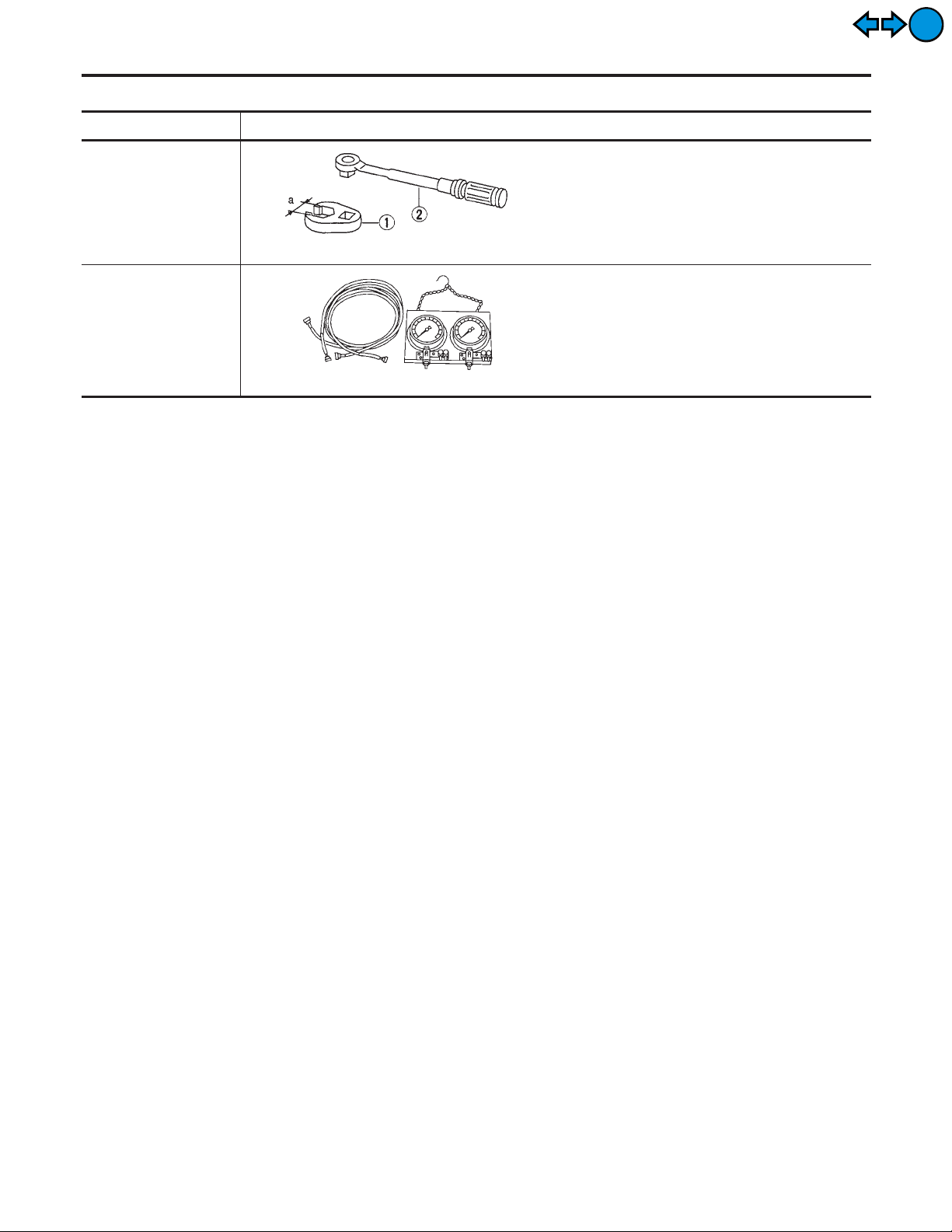
Tool name Description
1 Flare nut crowfoot
2 Torque wrench
NT360
Brake fluid pressure
gauge
NT151
Commercial Service Tools
Removing and installing each brake piping
a: 10 mm (0.39 in)
Measuring brake fluid pressure
NFBR0004
BR-6
NOISE, VIBRATION AND HARSHNESS (NVH) TROUBLESHOOTING
NVH Troubleshooting Chart
NFBR0005
EXIT
EXIT
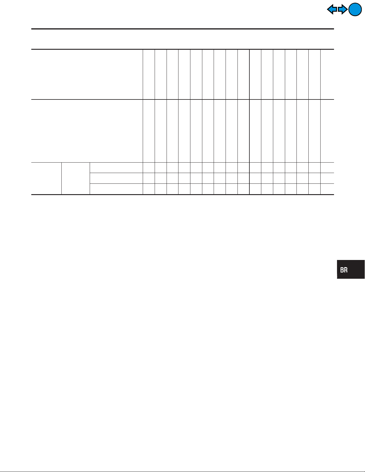
NVH Troubleshooting Chart
NFBR0005S01
Use the chart below to help you find the cause of the symptom. If necessary, repair or replace these parts.
Reference page
Possible cause and
SUSPECTED PARTS
Symptom BRAKE
X: Applicable
BR-24, 28
BR-24, 28
Pads - damaged
Pads - uneven wear
Noise X X X XXXXXX
Shake X XXXXXX
Shimmy, Judder XXXXXXX XXXXX
—
BR-24, 28
Shims damaged
Rotor imbalance
—
BR-26, 32
Rotor damage
Rotor runout
—
—
Rotor deformation
Rotor deflection
—
Rotor rust
BR-26, 32
NVH in AX section
Rotor thickness variation
DRIVE SHAFT
NVH in AX section
NVH in SU section
AXLE
SUSPENSION
NVH in SU section
TIRES
NVH in SU section
ROAD WHEEL
GI
MA
EM
NVH in ST section
LC
EC
FE
STEERING
CL
MT
AT
AX
SU
ST
RS
BT
HA
SC
BR-7
EL
IDX
Checking Brake Fluid Level
ON-VEHICLE SERVICE
EXIT
EXIT
SBR451D
SBR389C
SBR419C
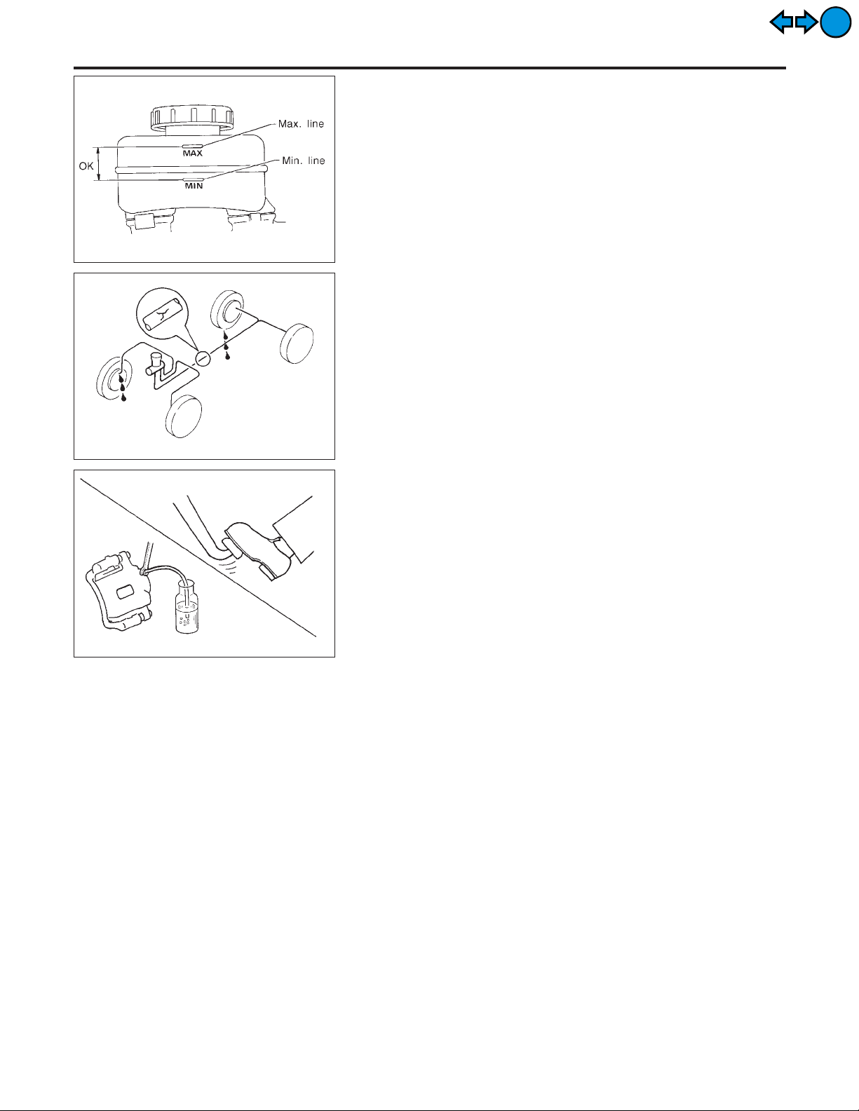
Checking Brake Fluid Level
NFBR0006
I Check fluid level in reservoir tank. It should be between Max
and Min lines on reservoir tank.
I If fluid level is extremely low, check brake system for leaks.
I Release parking brake lever and see if brake warning lamp
goes off. If not, check brake system for leaks.
Checking Brake Line
NFBR0007
CAUTION:
If leakage occurs around joints, retighten or, if necessary,
replace damaged parts.
1. Check brake lines (tubes and hoses) for cracks, deterioration
or other damage. Replace any damaged parts.
2. Check for oil leakage by fully depressing brake pedal while
engine is running.
Changing Brake Fluid
NFBR0008
CAUTION:
I Refill with new brake fluid “DOT 3”.
I Always keep fluid level higher than minimum line on res-
ervoir tank.
I Never reuse drained brake fluid.
I Be careful not to splash brake fluid on painted areas; it
may cause paint damage. If brake fluid is splashed on
painted areas, wash it away with water immediately.
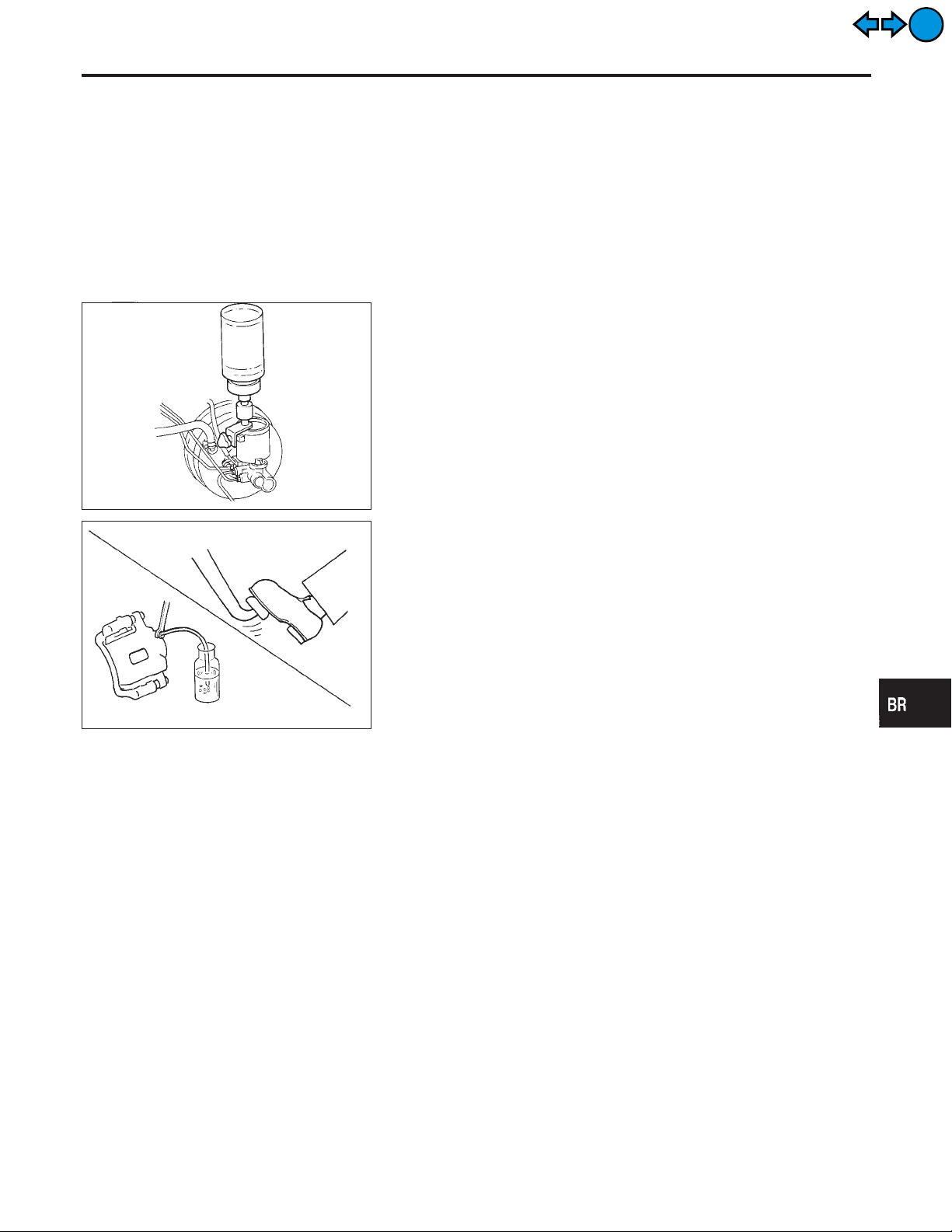
1. Clean inside of reservoir tank, and refill with new brake fluid.
2. Connect a vinyl tube to each air bleeder valve.
3. Drain brake fluid from each air bleeder valve by depressing
brake pedal.
4. Refill until brake fluid comes out of each air bleeder valve.
Use same procedure as in bleeding hydraulic system to refill
brake fluid. Refer to “Bleeding Brake System”, BR-9.
Brake Burnishing Procedure
NFBR0036
Burnish the brake contact surfaces according to the following procedure after refinishing or replacing drums or rotors, after replacing pads or linings, or if a soft pedal occurs at very low mileage.
CAUTION:
Only perform this procedure under safe road and traffic conditions. Use extreme caution.
1. Drive the vehicle on a straight smooth road at 50 km/h (31
MPH).
2. Use medium brake pedal/foot effort to bring the vehicle to a
complete stop from 50 km/h (31 MPH). Adjust brake pedal/foot
BR-8
ON-VEHICLE SERVICE
pressure such that vehicle stopping time equals 3 to 5 seconds.
3. To cool the brake system, drive the vehicle at 50 km/h (31
MPH) for 1 minute without stopping.
4. Repeat steps 1 to 3, 10 times or more to complete the burnishing procedure.
Bleeding Brake System
CAUTION:
I Carefully monitor brake fluid level at master cylinder dur-
ing bleeding operation.
I Fill reservoir with new brake fluid “DOT 3”. Make sure it is
full at all times while bleeding air out of system.
I Place a container under master cylinder to avoid spillage
of brake fluid.
I For models with ABS, turn ignition switch OFF and dis-
connect ABS actuator connectors or battery ground cable.
SBR995
I Bleed air in the following order.
Right rear brake , Left front brake , Left rear brake , Right
front brake
1. Connect a transparent vinyl tube to air bleeder valve.
2. Fully depress brake pedal several times.
3. With brake pedal depressed, open air bleeder valve to release
air.
4. Close air bleeder valve.
5. Release brake pedal slowly.
SBR419C
6. Repeat steps 2. through 5. until clear brake fluid comes out of
air bleeder valve.
Brake Burnishing Procedure (Cont’d)
NFBR0009
GI
MA
EM
LC
EC
FE
CL
MT
AT
AX
SU
EXIT
EXIT
BR-9
ST
RS
BT
HA
SC
EL
IDX
Hydraulic Circuit
BRAKE HYDRAULIC LINE
EXIT
EXIT
SBR992
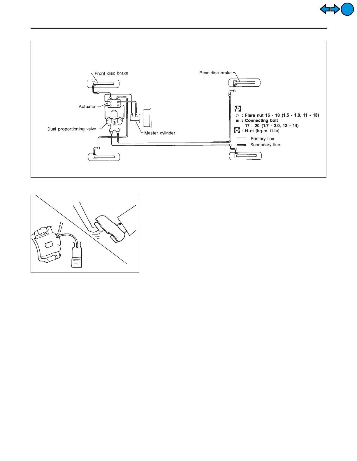
Hydraulic Circuit
Removal
NFBR0010
MBR151A
NFBR0011
CAUTION:
I Be careful not to splash brake fluid on painted areas; it
may cause paint damage. If brake fluid is splashed on
painted areas, wash it away with water immediately.
I All hoses must be free from excessive bending, twisting
and pulling.
1. Connect vinyl tube to air bleeder valve.
2. Drain brake fluid from each air bleeder valve by depressing
brake pedal.
3. Remove flare nut connecting brake tube and hose, then withdraw lock spring.
4. Cover openings to prevent entrance of dirt whenever disconnecting brake line.
Inspection
NFBR0012
Check brake lines (tubes and hoses) for cracks, deterioration or
other damage. Replace any damaged parts.
BR-10
BRAKE HYDRAULIC LINE
Installation
EXIT
EXIT
SBR686C
Installation
CAUTION:
I Refill with new brake fluid “DOT 3”.
I Never reuse drained brake fluid.
1. Tighten all flare nuts and connecting bolts.
Specification:
Flare nut
15 - 18 N·m (1.5 - 1.8 kg-m, 11 - 13 ft-lb)
Connecting bolt
17 - 20 N·m (1.7 - 2.0 kg-m, 12 - 14 ft-lb)
2. Refill until new brake fluid comes out of each air bleeder valve.
3. Bleed air. Refer to “Bleeding Brake System”, BR-9.
NFBR0013
GI
MA
EM
LC
EC
FE
CL
MT
AT
AX
SU
ST
RS
BT
HA
SC
BR-11
EL
IDX
Inspection
DUAL PROPORTIONING VALVE
EXIT
EXIT
SBR822BA
SBR823BA
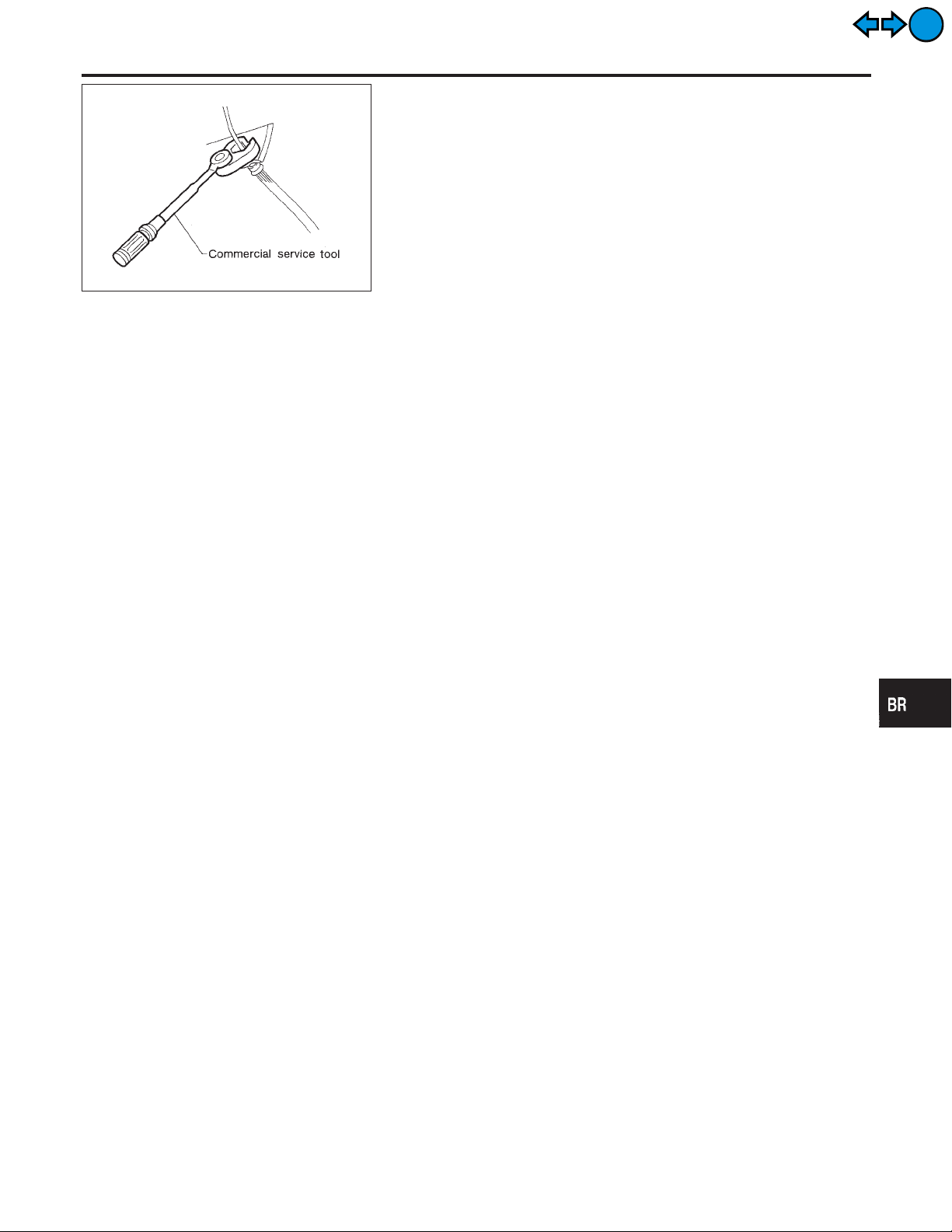
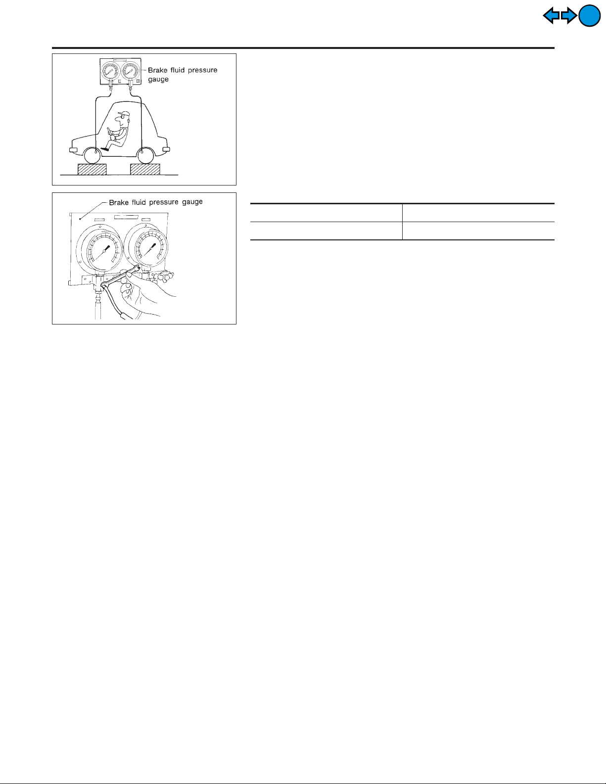
Inspection
NFBR0014
CAUTION:
I Carefully monitor brake fluid level at master cylinder.
I Use new brake fluid “DOT 3”.
I Be careful not to splash brake fluid on painted areas; it
may cause paint damage. If brake fluid is splashed on
paint areas, wash it away with water immediately.
1. Connect Tool to air bleeders of front and rear brakes on either
LH and RH side.
2. Bleed air from the Tool.
3. Check fluid pressure by depressing brake pedal.
Unit: kPa (kg/cm2, psi)
Applied pressure (Front brake) 7,355 (75, 1,067)
Output pressure (Rear brake) 5,100 - 5,492 (52 - 56, 739 - 796)
If output pressure is out of specification, replace dual proportioning valve.
4. Bleed air after disconnecting the Tool. Refer to “Bleeding Brake
System”, BR-9.
BR-12
BRAKE PEDAL AND BRACKET
Removal and Installation
EXIT
EXIT
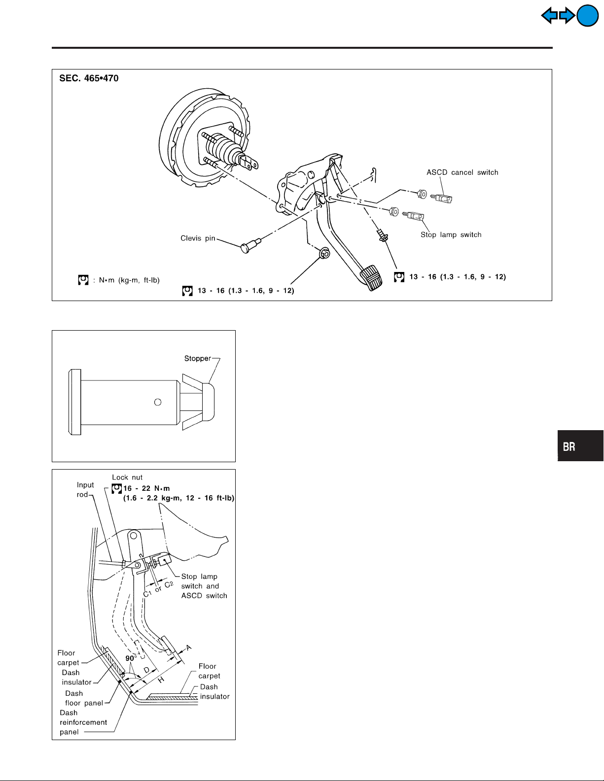
Removal and Installation
Inspection
Check brake pedal for following items.
I Brake pedal bend
I Clevis pin deformation
I Crack of any welded portion
I Crack or deformation of clevis pin stopper
NFBR0015
SBR525E
NFBR0016
GI
MA
EM
LC
EC
FE
CL
MT
AT
AX
SU
SBR997
SBR526E
Adjustment
Check brake pedal free height from metal panel. Adjust if necessary.
H: Free height
Refer to SDS, BR-115.
: Clearance between pedal stopper and threaded
C
1,C2
end of stop lamp switch and ASCD switch
0.74 - 1.96 mm (0.0291 - 0.0772 in)
NFBR0017
ST
RS
BT
HA
SC
EL
IDX
BR-13
Adjustment (Cont’d)
BRAKE PEDAL AND BRACKET
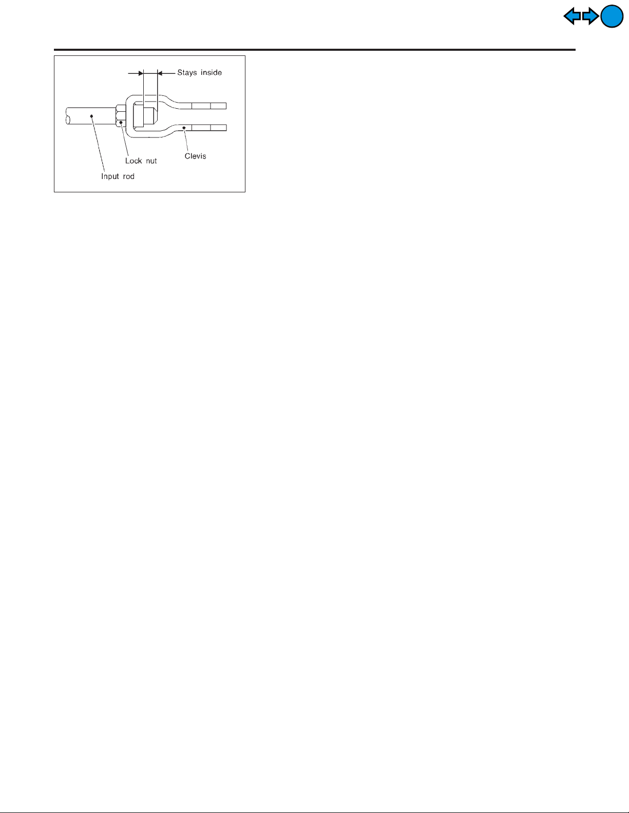
1. Loosen lock nut and adjust pedal free height by turning brake
booster input rod. Then tighten lock nut.
2. Check pedal free play.
Make sure that stop lamps go off when pedal is released.
3. Check brake pedal’s depressed height while engine is running.
If lower than specification, check brake system for leaks, accumulation of air or any damage to components (master cylinder,
wheel cylinder, etc.); then make necessary repairs.
SBR229E
EXIT
EXIT
BR-14
MASTER CYLINDER (TOKICO)
Removal
EXIT
EXIT
Removal
NFBR0018
GI
MA
EM
LC
EC
FE
CL
MT
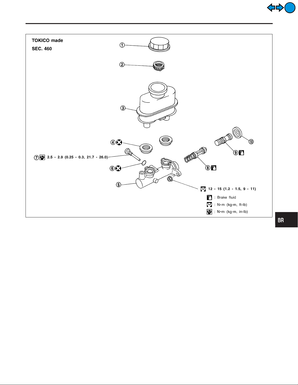
1. Reservoir cap
2. Oil filter
3. Reservoir tank
4. Seal
5. Cylinder body
6. O-ring
7. Piston stopper
CAUTION:
Be careful not to splash brake fluid on painted areas; it may
cause paint damage. If brake fluid is splashed on painted
areas, wash it away with water immediately.
1. Connect a vinyl tube to air bleeder valve.
2. Drain brake fluid from each air bleeder valve, depressing brake
pedal to empty fluid from master cylinder.
3. Remove brake pipe flare nuts.
4. Remove master cylinder mounting nuts.
8. Secondary piston assembly
9. Primary piston assembly
10. Stopper cap
AT
AX
SU
SBR554E
ST
RS
BT
HA
SC
BR-15
EL
IDX
Disassembly
MASTER CYLINDER (TOKICO)
EXIT
EXIT
SBR938A
SBR231C
Disassembly
NFBR0019
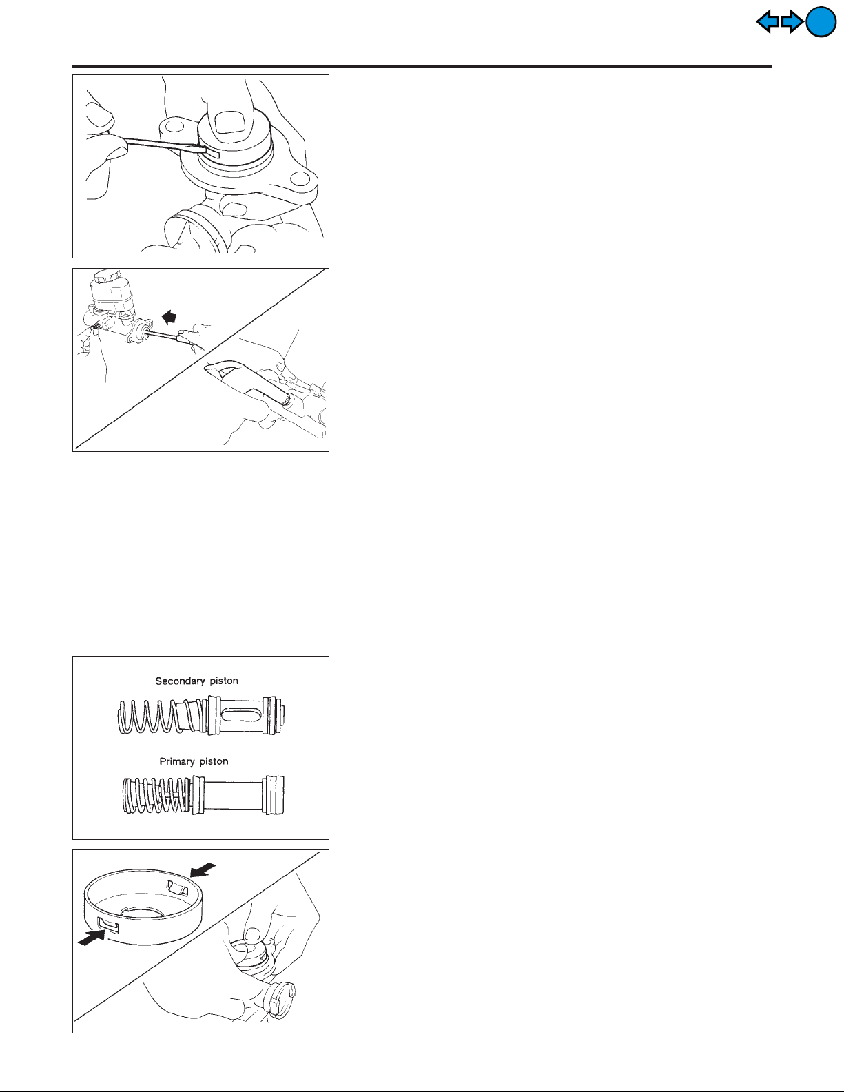
1. Bend claws of stopper cap outward and remove stopper cap.
2. Remove valve stopper while piston is pushed into cylinder.
3. Remove piston assemblies.
If it is difficult to remove secondary piston assembly,
gradually apply compressed air through fluid outlet.
4. Draw out reservoir tank.
Inspection
NFBR0020
Check for the following items.
Replace any part if damaged.
Master cylinder:
I Pin holes or scratches on inner wall.
Piston:
I Deformation of or scratches on piston cups.
SBR354C
SBR940A
Assembly
NFBR0021
1. Insert secondary piston assembly. Then insert primary piston
assembly.
I Pay attention to alignment of secondary piston slit with valve
stopper mounting hole of cylinder body.
2. Install stopper cap.
Before installing stopper cap, ensure that claws are bent
inward.
3. Push reservoir tank seals into cylinder body.
4. Push reservoir tank into cylinder body.
BR-16
MASTER CYLINDER (TOKICO)
5. Install valve stopper while piston is pushed into cylinder.
Assembly (Cont’d)
GI
MA
EM
EXIT
EXIT
SBR222B
SBR704C
Installation
CAUTION:
I Refill with new brake fluid “DOT 3”.
I Never reuse drained brake fluid.
1. Place master cylinder onto brake booster and secure mounting nuts lightly.
2. Torque mounting nuts.
: 12 - 15 N·m (1.2 - 1.5 kg-m,9-11ft-lb)
3. Fill up reservoir tank with new brake fluid.
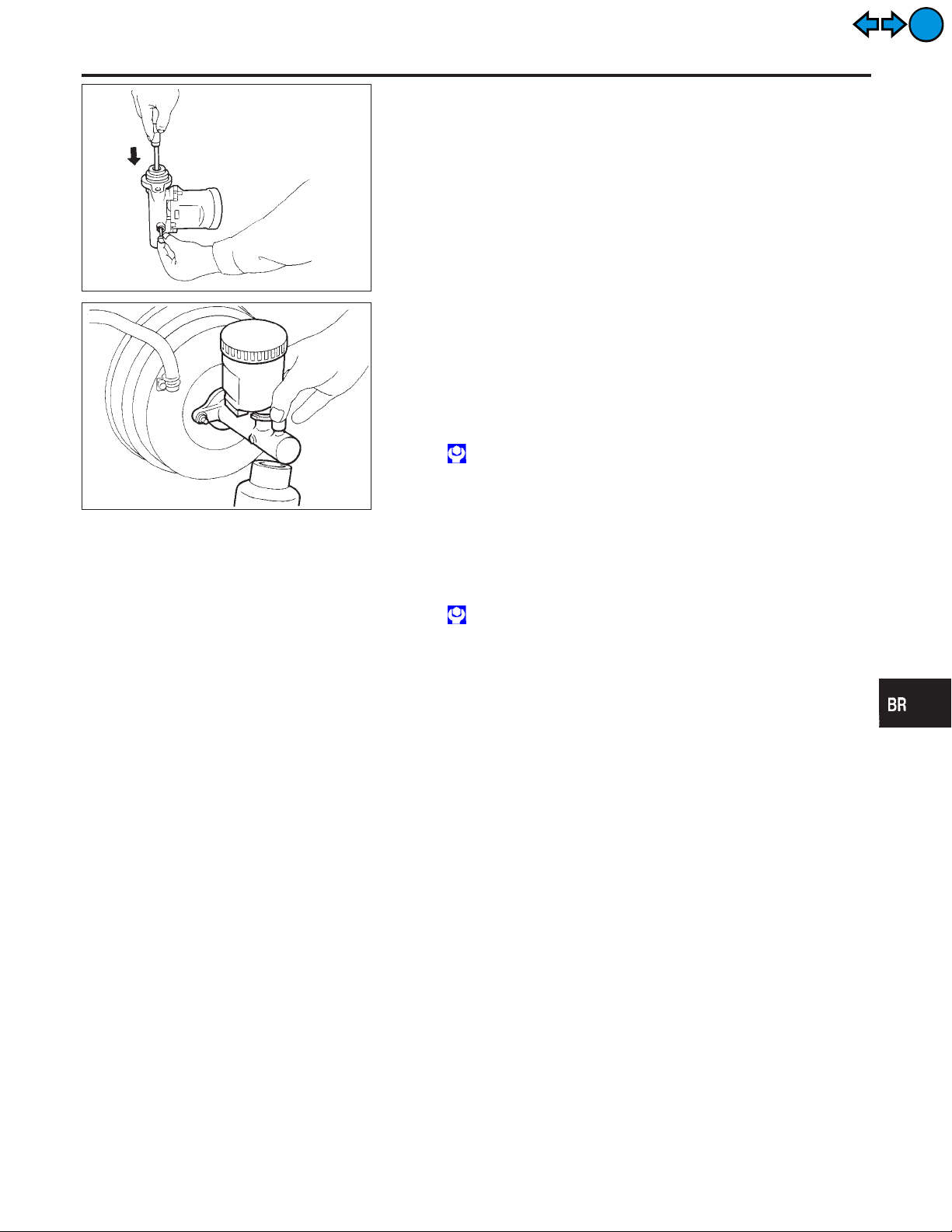
4. Plug all ports on master cylinder with fingers to prevent air
suction while releasing brake pedal.
5. Have driver depress brake pedal slowly several times until no
air comes out of master cylinder.
6. Fit brake lines to master cylinder.
7. Tighten flare nuts.
: 15 - 18 N·m (1.5 - 1.8 kg-m, 11 - 13 ft-lb)
8. Bleed air from brake system. Refer to “Bleeding Brake
System”, BR-9.
NFBR0022
LC
EC
FE
CL
MT
AT
AX
SU
BR-17
ST
RS
BT
HA
SC
EL
IDX
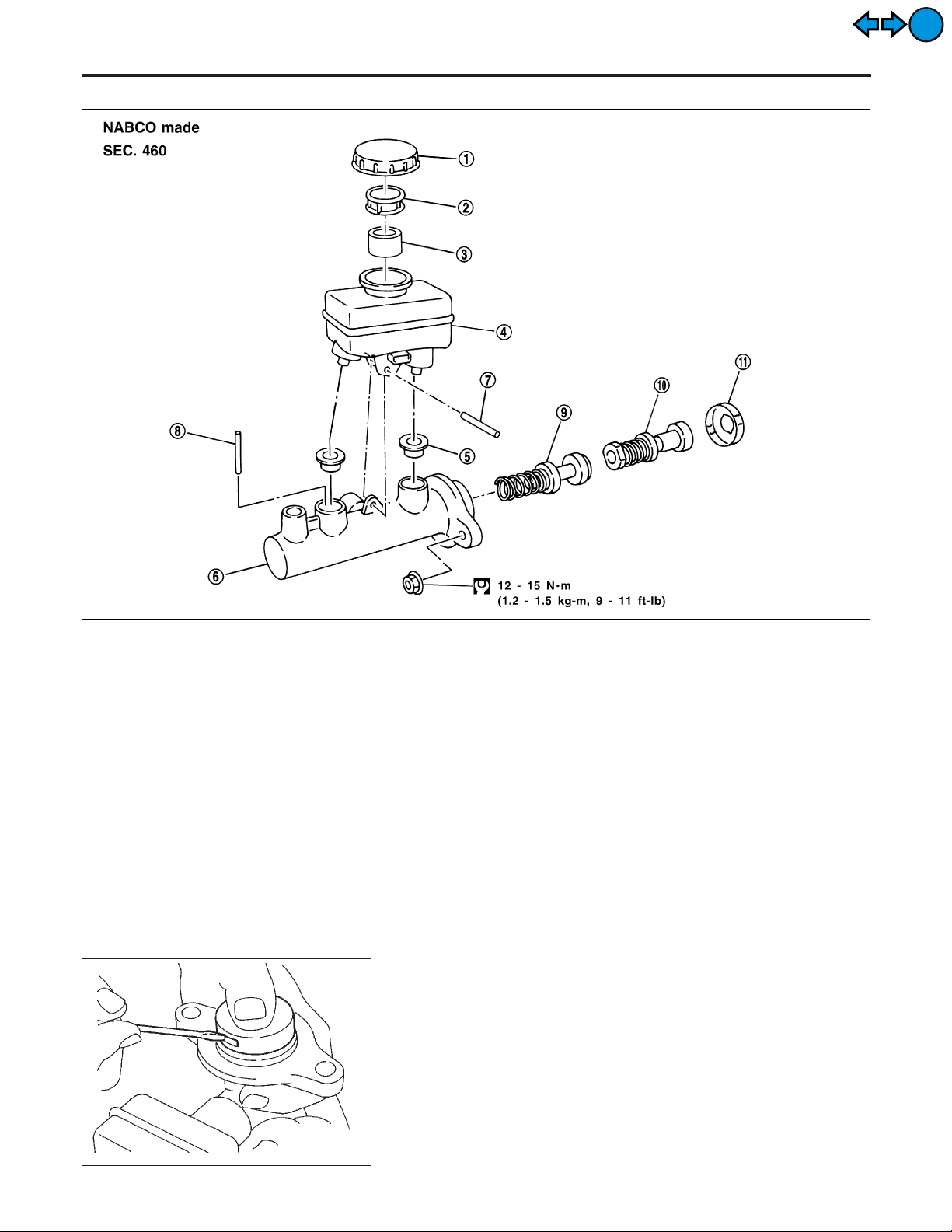
Removal
MASTER CYLINDER (NABCO)
EXIT
EXIT
Removal
NFBR0095
1. Reservoir cap
2. Oil filter
3. Float
4. Reservoir tank
5. Seal
6. Cylinder body
7. Spring pin
8. Piston stopper pin
9. Secondary piston assembly
10. Primary piston assembly
11. Stopper cap
CAUTION:
Be careful not to splash brake fluid on painted areas; it may
cause paint damage. If brake fluid is splashed on painted
areas, wash it away with water immediately.
1. Connect a vinyl tube to air bleeder valve.
2. Drain brake fluid from each air bleeder valve, depressing brake
pedal to empty fluid from master cylinder.
3. Remove brake pipe flare nuts.
4. Remove master cylinder mounting nuts.
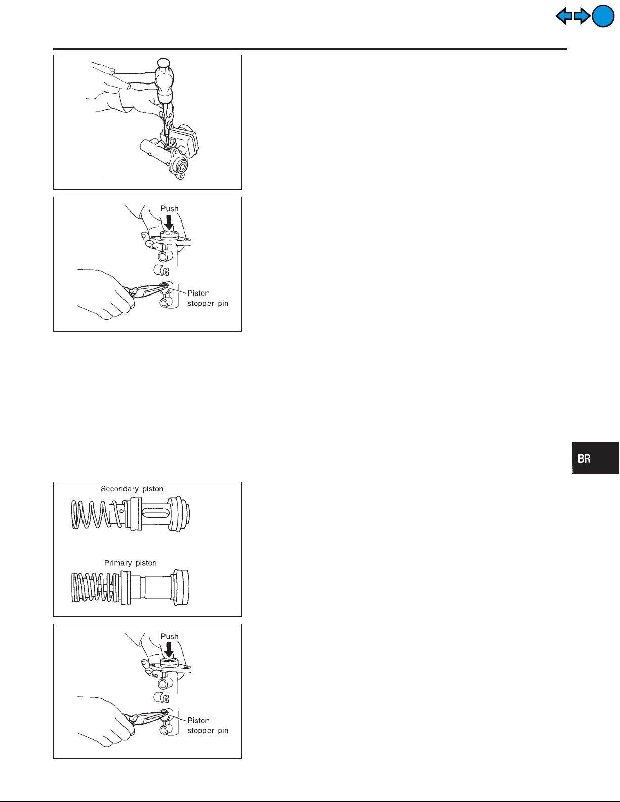
Disassembly
1. Bend claws of stopper cap outward and remove stopper cap.
SBR555E
NFBR0096
SBR234E
BR-18
MASTER CYLINDER (NABCO)
2. Drive out spring pin from cylinder body.
3. Draw out reservoir tank and seals.
Disassembly (Cont’d)
GI
MA
EM
EXIT
EXIT
SBR231E
SBR232E
4. Remove piston stopper pin while piston is pushed into cylinder.
5. Remove piston assemblies.
If it is difficult to remove secondary piston assembly,
gradually apply compressed air through fluid outlet.
Inspection
Check for the following items.
Replace any part if damaged.
Master cylinder:
I Pin holes or scratches on inner wall.
Piston:
I Deformation of or scratches on piston cups.
NFBR0097
LC
EC
FE
CL
MT
AT
AX
SU
SBR233E
SBR232E
Assembly
1. Insert secondary piston assembly. Then insert primary piston
assembly.
I Pay attention to alignment of secondary piston slit with
valve stopper mounting hole of cylinder body.
2. Install piston stopper pin while piston is pushed into cylinder.
3. Push reservoir tank seals and reservoir tank into cylinder body.
4. Install spring pin.
NFBR0098
BR-19
ST
RS
BT
HA
SC
EL
IDX
Assembly (Cont’d)
MASTER CYLINDER (NABCO)
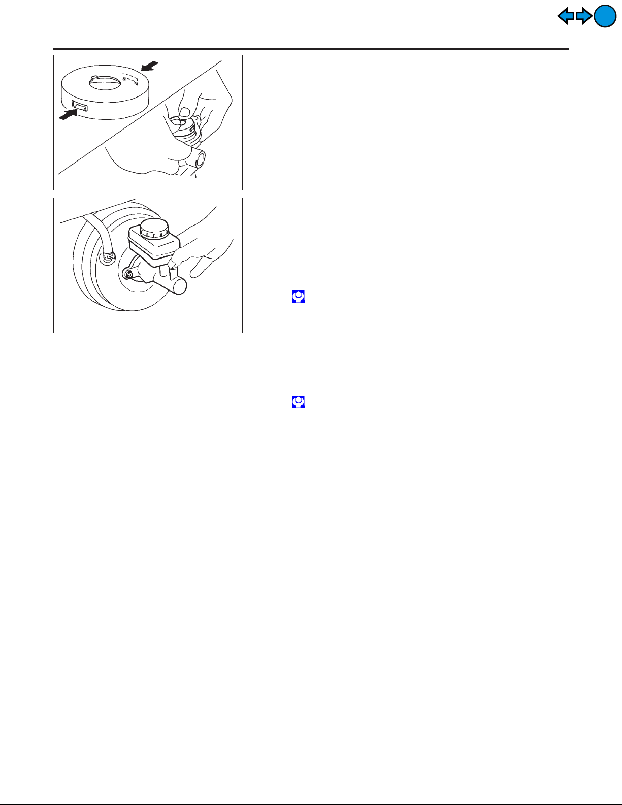
5. Install stopper cap.
Before installing stopper cap, ensure that claws are bent
inward.
SBR235E
EXIT
EXIT
SBR236E
Installation
NFBR0099
CAUTION:
I Refill with new brake fluid “DOT 3”.
I Never reuse drained brake fluid.
1. Place master cylinder onto brake booster and secure mounting nuts lightly.
2. Torque mounting nuts.
: 12 - 15 N·m (1.2 - 1.5 kg-m,9-11ft-lb)
3. Fill up reservoir tank with new brake fluid.
4. Plug all ports on master cylinder with fingers to prevent air
suction while releasing brake pedal.
5. Have driver depress brake pedal slowly several times until no
air comes out of master cylinder.
6. Fit brake lines to master cylinder.
7. Tighten flare nuts.
: 15 - 18 N·m (1.5 - 1.8 kg-m, 11 - 13 ft-lb)
8. Bleed air from brake system.
BR-20
BRAKE BOOSTER
On-vehicle Service
EXIT
EXIT
SBR002A
SBR365AA
On-vehicle Service
OPERATING CHECK
1. Stop engine and depress brake pedal several times. Check
that pedal stroke does not change.
2. Depress brake pedal, then start engine. If pedal goes down
slightly, operation is normal.
AIRTIGHT CHECK
1. Start engine, and stop it after one or two minutes. Depress
brake pedal several times slowly. The pedal should go further
down the first time, and then it should gradually rise thereafter.
2. Depress brake pedal while engine is running, and stop engine
with pedal depressed. The pedal stroke should not change
after holding pedal down for 30 seconds.
Removal
CAUTION:
I Be careful not to splash brake fluid on painted areas; it
may cause paint damage. If brake fluid is splashed on
painted areas, wash it away with water immediately.
I Be careful not to deform or bend brake pipes, during
removal of booster.
NFBR0023
NFBR0023S01
NFBR0023S02
NFBR0024
GI
MA
EM
LC
EC
FE
CL
MT
AT
AX
SU
SBR232CB
SBR208E
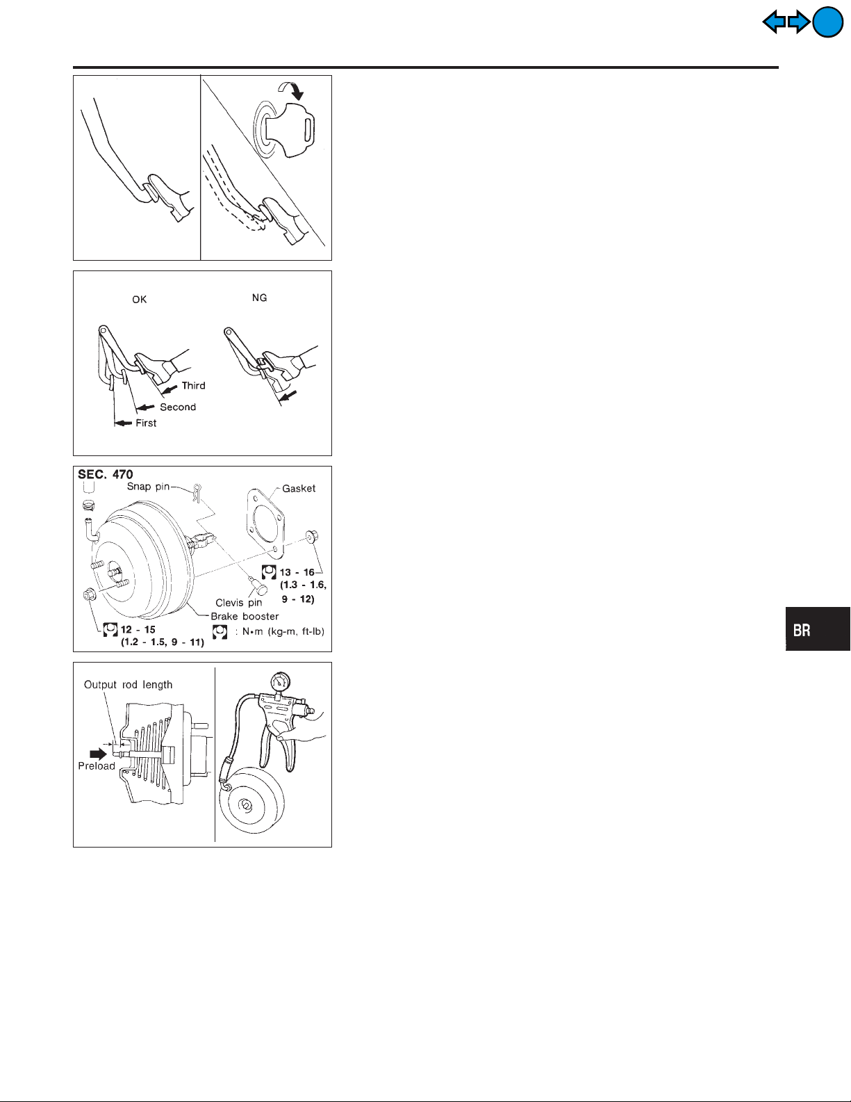
Inspection
OUTPUT ROD LENGTH CHECK
1. Apply vacuum of −66.7 kPa (−500 mmHg, −19.69 inHg) to
brake booster with a handy vacuum pump.
2. Add preload of 19.6 N (2 kg, 4.4 lb) to output rod.
3. Check output rod length.
Specified length:
10.275 - 10.525 mm (0.4045 - 0.4144 in)
NFBR0025
NFBR0025S01
ST
RS
BT
HA
SC
EL
IDX
BR-21
Installation
BRAKE BOOSTER
EXIT
EXIT
SBR237EB
Installation
NFBR0026
CAUTION:
I Be careful not to deform or bend brake pipes, during
installation of booster.
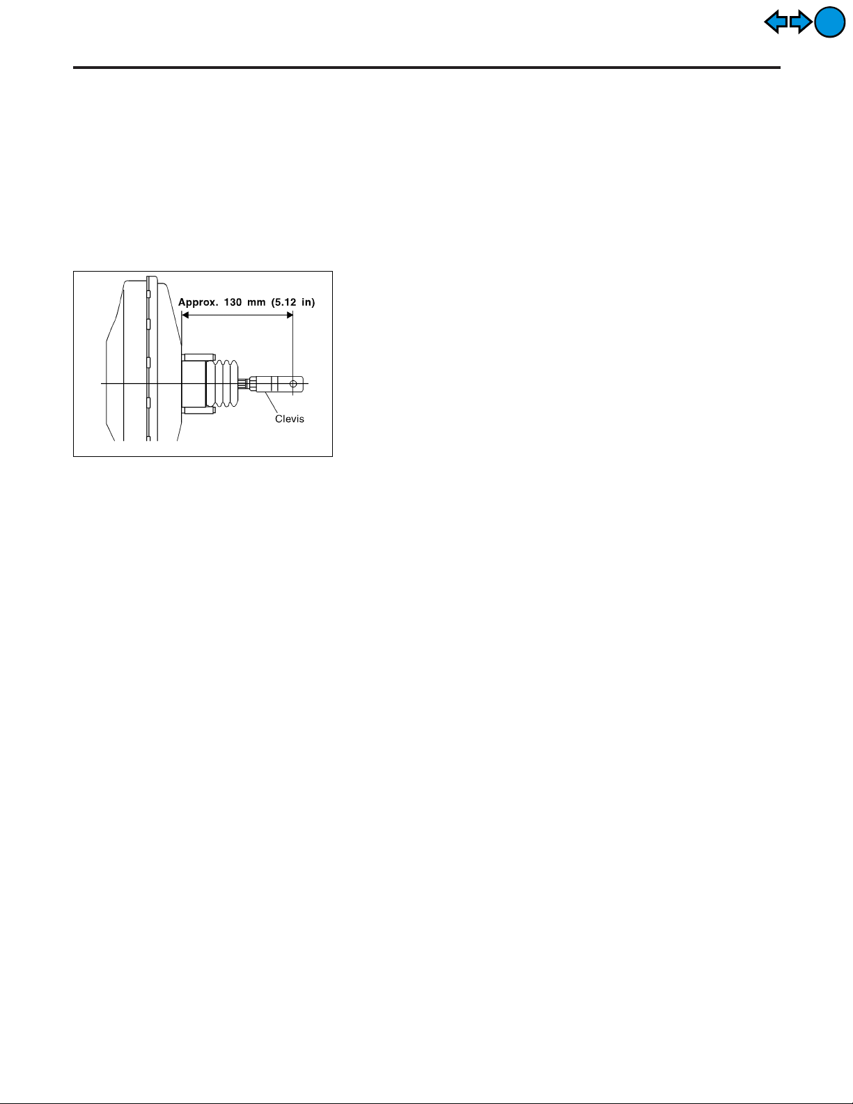
I Replace clevis pin if damaged.
I Refill with new brake fluid “DOT 3”.
I Never reuse drained brake fluid.
I Take care not to damage brake booster mounting bolt
thread when installing. Due to the acute angle of
installation, the threads can be damaged with the dash
panel.
1. Before fitting booster, temporarily adjust clevis to dimension
shown.
2. Fit booster, then secure mounting nuts (brake pedal bracket to
master cylinder) lightly.
3. Connect brake pedal and booster input rod with clevis pin.
4. Secure mounting nuts.
Specification:
13 - 16 N·m (1.3 - 1.6 kg-m,9-12ft-lb)
5. Install master cylinder. Refer to “Installation” in “MASTER
CYLINDER”, BR-17.
6. Bleed air. Refer to “Bleeding Brake System”, BR-9.
BR-22
VACUUM HOSE
Removal and Installation
EXIT
EXIT
SBR225B
Removal and Installation
CAUTION:
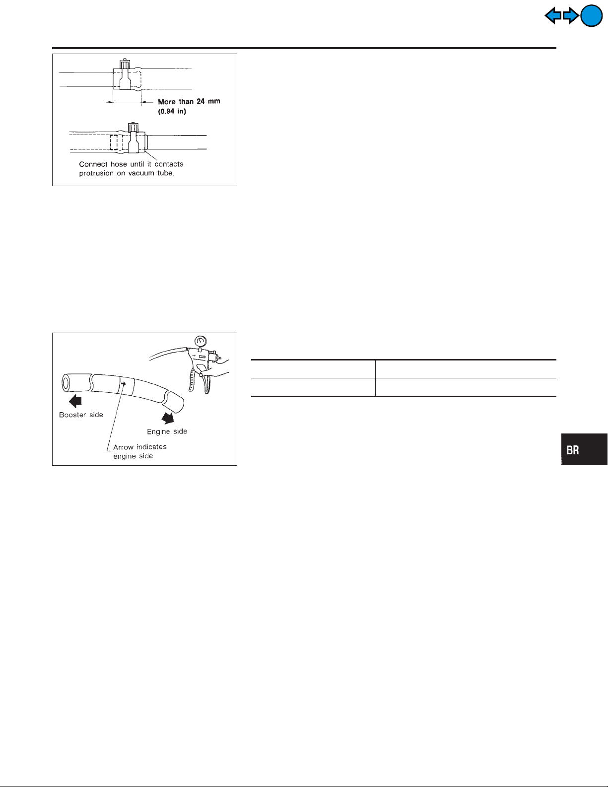
When installing vacuum hoses, pay attention to the following
points.
I Do not apply any oil or lubricants to vacuum hose and
check valve.
I Insert vacuum tube into vacuum hose as shown.
I Install check valve, paying attention to its direction.
Inspection
HOSES AND CONNECTORS
Check vacuum lines, connections and check valve for airtightness,
improper attachment chafing and deterioration.
CHECK VALVE
Check vacuum with a vacuum pump.
NFBR0027
NFBR0028
NFBR0028S01
NFBR0028S02
GI
MA
EM
LC
EC
FE
CL
MT
AT
SBR844B
Connect to booster side Vacuum should exist.
Connect to engine side Vacuum should not exist.
AX
SU
ST
RS
BT
HA
SC
EL
BR-23
IDX
Component
FRONT DISC BRAKE
EXIT
EXIT
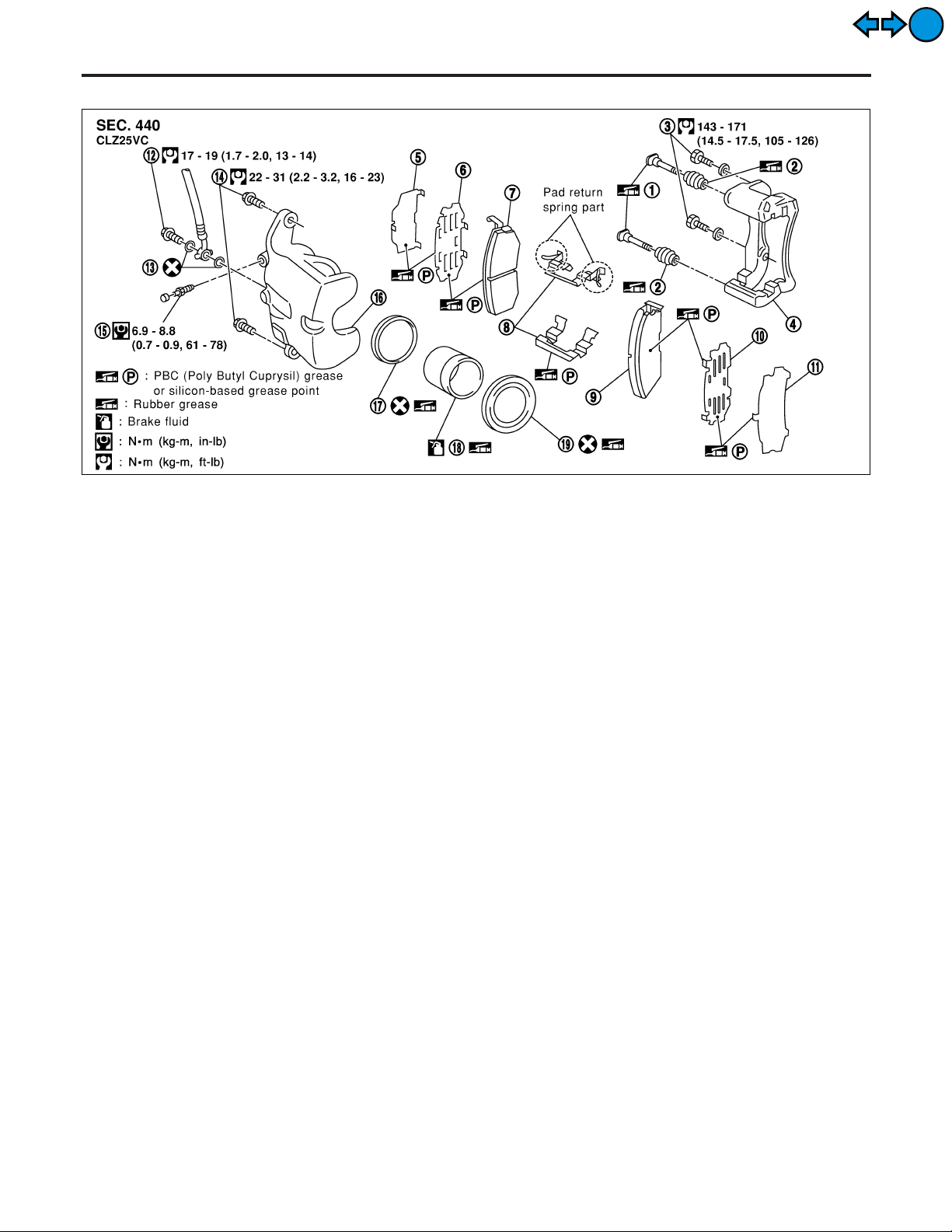
1. Main pin
2. Pin boot
3. Torque member fixing bolt
4. Torque member
5. Shim cover
6. Inner shim
7. Inner pad
Component
8. Pad retainer
9. Outer pad
10. Outer shim
11. Shim cover
12. Connecting bolt
13. Copper washer
NFBR0030
SBR527EA
14. Main pin bolt
15. Bleed valve
16. Cylinder body
17. Piston seal
18. Piston
19. Piston boot
Pad Replacement
NFBR0029
WARNING:
Clean brake pads with a vacuum dust collector to minimize the
hazard of airborne particles or other materials.
CAUTION:
I When cylinder body is open, do not depress brake pedal
because piston will pop out.
I Be careful not to damage piston boot or get oil on rotor.
Always replace shims when replacing pads.
I If shims are rusted or show peeling of the rubber coat,
replace them with new shims.
I It is not necessary to remove connecting bolt except for
disassembly or replacement of caliper assembly. In this
case, suspend cylinder body with wire so as not to stretch
brake hose.
I Burnish the brake contact surfaces after refinishing or
replacing drums or rotors, after replacing pads or linings,
or if a soft pedal occurs at very low mileage.
Refer to “Brake Burnishing Procedure”, “ON-VEHICLE
SERVICE”, BR-8.
BR-24
SBR976B
FRONT DISC BRAKE
Pad Replacement (Cont’d)
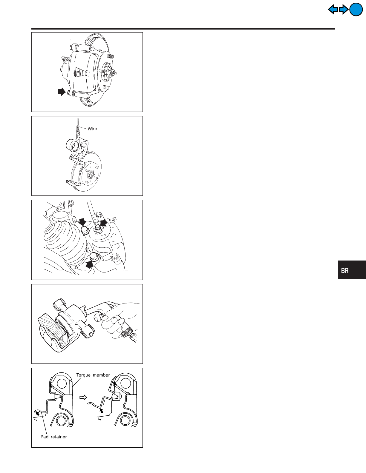
1. Remove master cylinder reservoir cap.
2. Remove pin bolt.
3. Open cylinder body upward. Then remove pad with retainers,
inner and outer shims.
Standard pad thickness:
11 mm (0.43 in)
Pad wear limit:
2.0 mm (0.079 in)
Carefully monitor brake fluid level because brake fluid will
return to reservoir when pushing back piston.
GI
MA
EM
LC
EC
FE
CL
EXIT
EXIT
SBR932C
SBR979B
SBR772
Removal
WARNING:
Clean brake pads with a vacuum dust collector to minimize the
hazard of airborne particles or other materials.
Remove torque member fixing bolts and connecting bolt.
It is not necessary to remove connecting bolt except for disassembly or replacement of caliper assembly. In this case,
suspend caliper assembly with wire so as not to stretch brake
hose.
Disassembly
WARNING:
Do not place your fingers in front of piston.
CAUTION:
Do not scratch or score cylinder wall.
1. Push out piston with piston boot with compressed air.
2. Remove piston seal with a suitable tool.
CAUTION:
When removing the pad retainer from the torque member, lift
it up and out in the direction of the arrows in the figure.
NFBR0031
NFBR0032
MT
AT
AX
SU
ST
RS
BT
HA
SC
EL
SBR556E
IDX
BR-25
Inspection
FRONT DISC BRAKE
EXIT
EXIT
Inspection
CALIPER
Cylinder Body
NFBR0033
NFBR0033S01
NFBR0033S0101
I Check inside surface of cylinder for score, rust, wear, damage
or presence of foreign materials. If any of the above conditions
are observed, replace cylinder body.
I Minor damage from rust or foreign materials may be eliminated
by polishing surface with a fine emery paper. Replace cylinder
body if necessary.
CAUTION:
Use brake fluid to clean. Never use mineral oil.
Piston
NFBR0033S0102
CAUTION:
Piston sliding surface is plated. Do not polish with emery
paper even if rust or foreign materials are stuck to sliding
surface.
Check piston for score, rust, wear, damage or presence of foreign
materials. Replace if any of the above conditions are observed.
Slide Pin, Pin Bolt and Pin Boot
NFBR0033S0103
Check for wear, cracks or other damage. Replace if any of the
above conditions are observed.
ROTOR
Rubbing Surface
NFBR0033S02
NFBR0033S0201
Check rotor for roughness, cracks or chips.
SBR219C
Runout
NFBR0033S0202
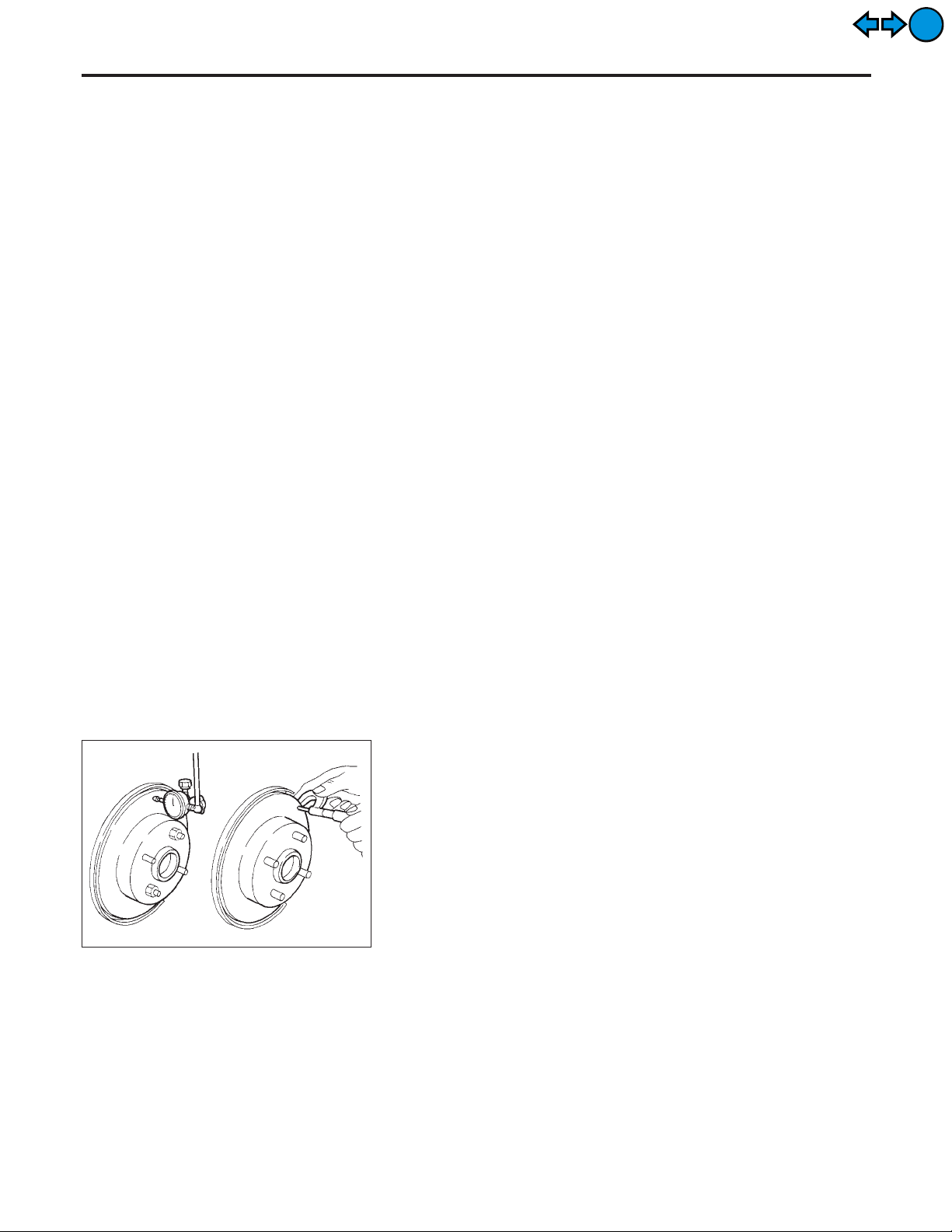
1. Secure rotor to wheel hub with at least two nuts (M12 x 1.25).
2. Check runout using a dial indicator.
Make sure that wheel bearing axial end play is within the
specifications before measuring. Refer to AX section
(“Front Wheel Bearing”, “ON-VEHICLE SERVICE”).
Maximum runout:
0.07 mm (0.0028 in)
3. If the runout is out of specification, find minimum runout position as follows:
a. Remove nuts and rotor from wheel hub.
b. Shift the rotor one hole and secure rotor to wheel hub with
nuts.
c. Measure runout.
d. Repeat steps a. to c. so that minimum runout position can be
found.
4. If the runout is still out of specification, turn rotor with on-car
brake lathe (“MAD, DL-8700”, “AMMCO 700 and 705” or
equivalent).
BR-26
FRONT DISC BRAKE
Inspection (Cont’d)
EXIT
EXIT
SBR574
Thickness
Thickness variation (At least 8 positions):
Maximum 0.01 mm (0.0004 in)
If thickness variation exceeds the specification, turn rotor with oncar brake lathe.
Rotor repair limit:
24.0 mm (0.945 in)
Assembly
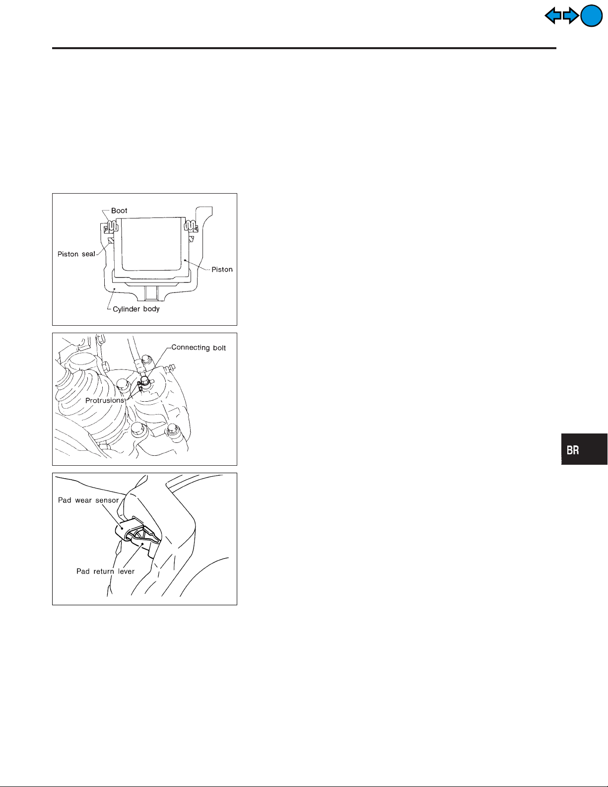
1. Insert piston seal into groove on cylinder body.
2. With piston boot fitted to piston, insert piston boot into groove
on cylinder body and install piston.
3. Properly secure piston boot.
Installation
CAUTION:
I Refill with new brake fluid “DOT 3”.
I Never reuse drained brake fluid.
1. Install brake hose to caliper securely.
2. Install all parts and secure all bolts.
3. Bleed air. Refer to “Bleeding Brake System”, BR-9.
NFBR0033S0203
NFBR0034
NFBR0035
GI
MA
EM
LC
EC
FE
CL
MT
AT
AX
SU
SBR980B
SBR557E
CAUTION:
The upper pad retainer is built so the pad returns to its original position. Be careful to install the pad-return lever securely
to the pad wear sensor, as shown in the left figure.
ST
RS
BT
HA
SC
EL
IDX
BR-27
Component
REAR DISC BRAKE
EXIT
EXIT
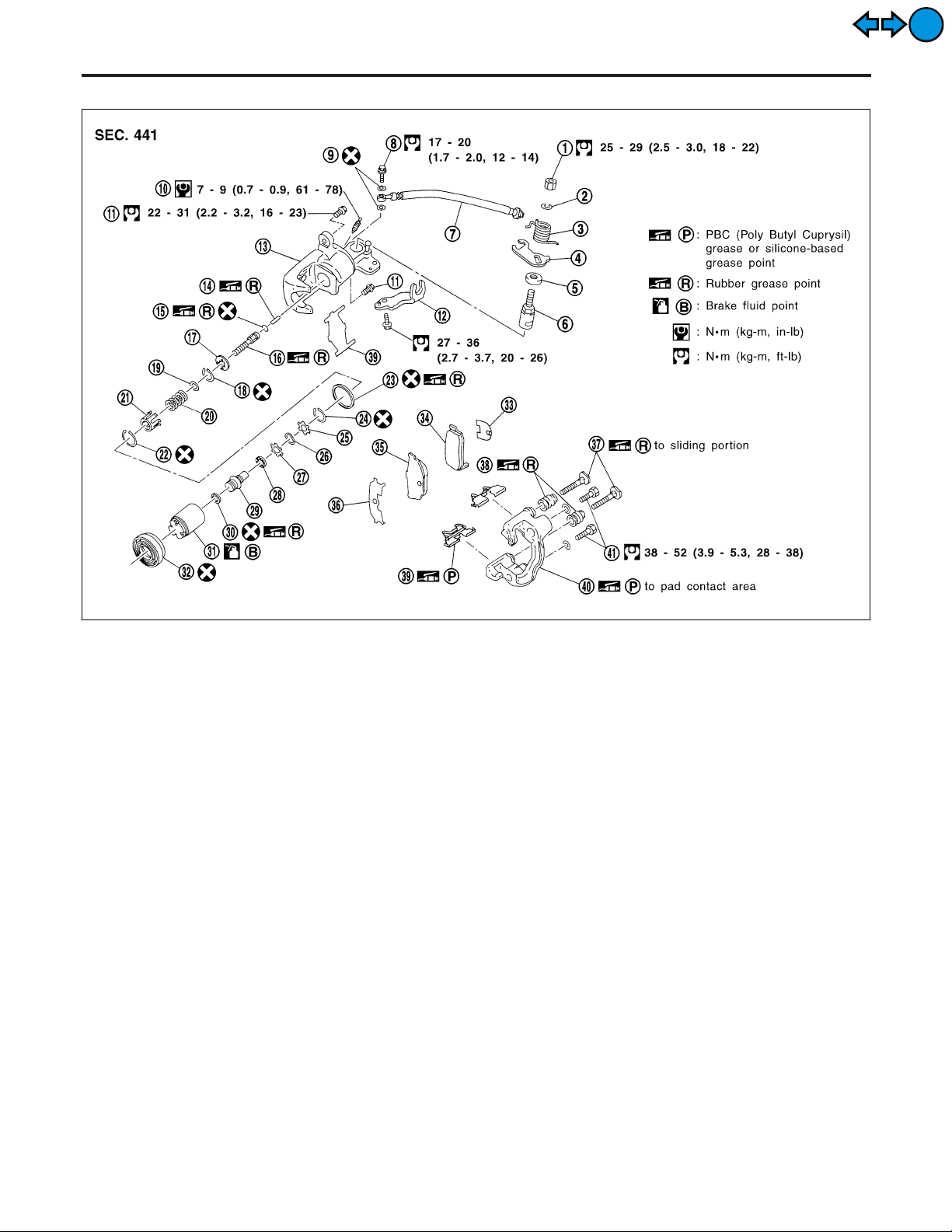
Component
NFBR0038
1. Nut
2. Washer
3. Return spring
4. Parking brake lever
5. Cam boot
6. Cam
7. Brake hose
8. Connecting bolt
9. Copper washer
10. Bleed screw
11. Pin bolt
12. Cable mounting bracket
13. Cylinder
14. Strut
15. O-ring
16. Push rod
17. Key plate
18. Ring C
19. Seat
20. Spring
21. Spring cover
22. Ring B
23. Piston seal
24. Ring A
25. Spacer
26. Wave washer
27. Spacer
28. Ball bearing
29. Adjust nut
30. Cup
31. Piston
32. Dust seal
33. Inner shim
34. Inner pad
35. Outer pad
36. Outer shim
37. Pin
38. Pin boot
39. Pad retainer
40. Torque member
41. Torque member fixing bolt
Pad Replacement
WARNING:
Clean brake pads with a vacuum dust collector to minimize the
hazard of airborne particles or other materials.
CAUTION:
I When cylinder body is open, do not depress brake pedal
because piston will pop out.
I Be careful not to damage piston boot or get oil on rotor.
Always replace shims in replacing pads.
I If shims are rusted or show peeling of rubber coat, replace
them with new shims.
SBR558E
NFBR0037
BR-28
SBR938C
REAR DISC BRAKE
Pad Replacement (Cont’d)
I It is not necessary to remove connecting bolt except for
disassembly or replacement of caliper assembly. In this
case, suspend cylinder body with wire so as not to stretch
brake hose.
I Burnish the brake contact surfaces after refinishing or
replacing drums or rotors, after replacing pads or linings,
or if a soft pedal occurs at very low mileage.
Refer to “Brake Burnishing Procedure”, “ON-VEHICLE
SERVICE”, BR-8.
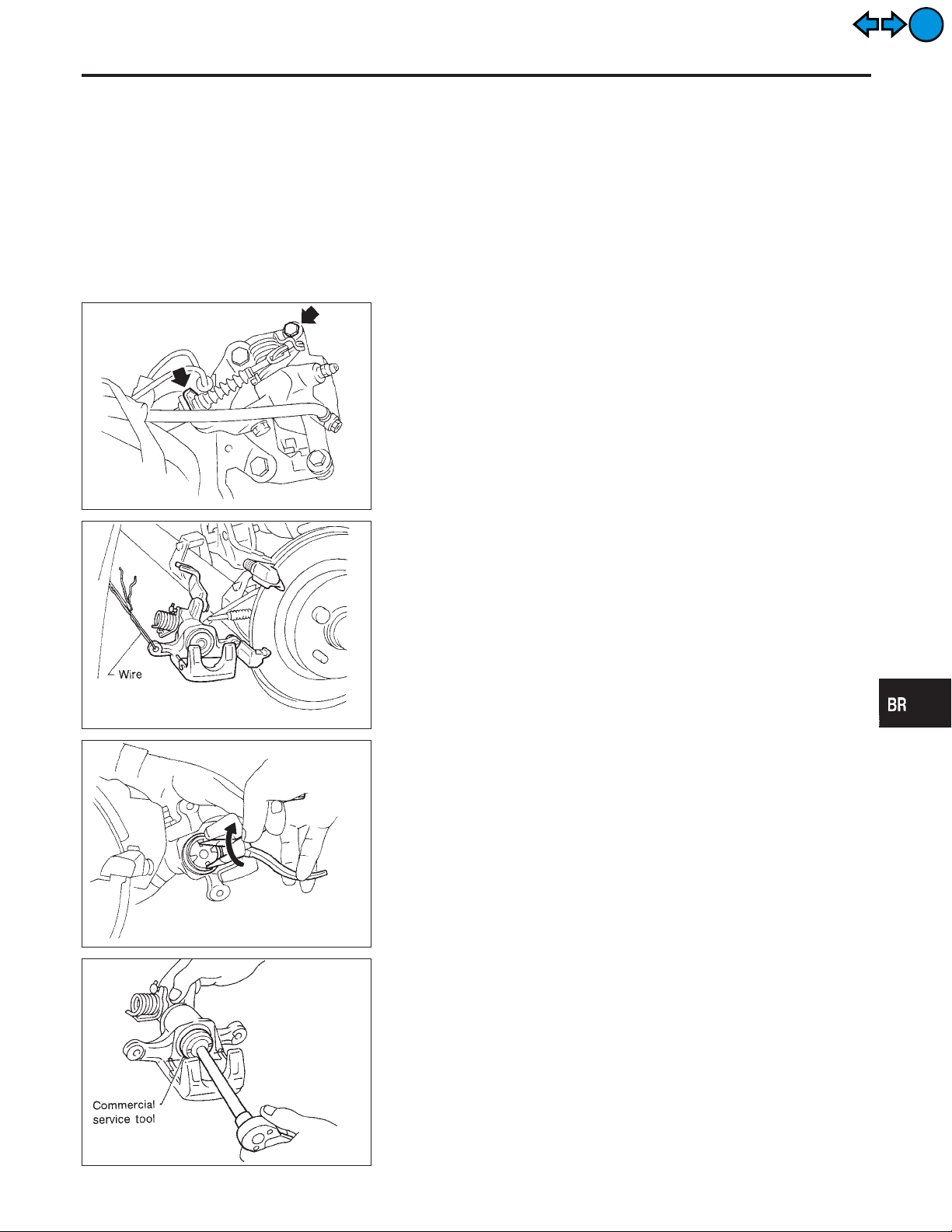
1. Remove master cylinder reservoir cap.
2. Remove brake cable mounting bolt and lock spring.
3. Release parking brake control lever, then disconnect cable
from the caliper.
4. Remove upper pin bolt.
5. Open cylinder body downward. Then remove pad retainers,
and inner and outer shims.
Standard pad thickness:
10 mm (0.39 in)
Pad wear limit:
1.5 mm (0.059 in)
GI
MA
EM
LC
EC
FE
CL
MT
EXIT
EXIT
SBR916C
SBR641
6. When installing new pads, push piston into cylinder body by
gently turning piston clockwise, as shown.
Carefully monitor brake fluid level because brake fluid will
return to reservoir when pushing back piston.
AT
AX
SU
ST
RS
BT
HA
SC
SBR868C
EL
IDX
BR-29
Pad Replacement (Cont’d)
SBR306E
REAR DISC BRAKE
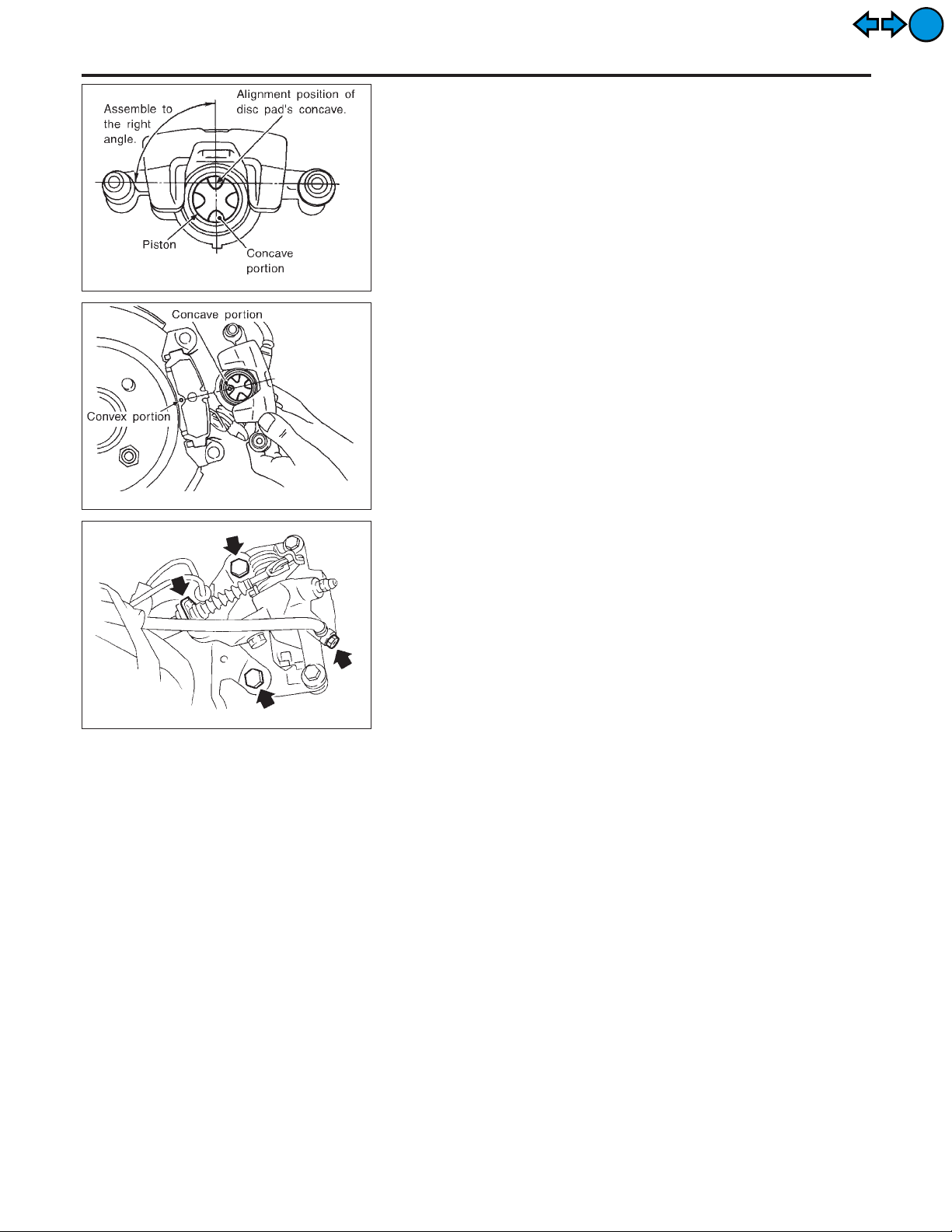
7. Adjust the piston to the right angle as shown in the figure.
8. As shown in the figure, align the piston’s concave to the pad’s
convex, then install the cylinder body to the torque member.
EXIT
EXIT
SBR307E
SBR939C
Removal
NFBR0039
WARNING:
Clean brake pads with a vacuum dust collector to minimize the
hazard of airborne particles or other materials.
1. Remove brake cable mounting bolt and lock spring.
2. Release parking brake control lever, then disconnect cable
from the caliper.
3. Remove torque member fixing bolts and connecting bolt.
It is not necessary to remove connecting bolt except for disassembly or replacement of caliper assembly. In this case,
suspend caliper assembly with wire so as not to stretch brake
hose.
BR-30

REAR DISC BRAKE
Disassembly
EXIT
EXIT
SBR868C
SBR646
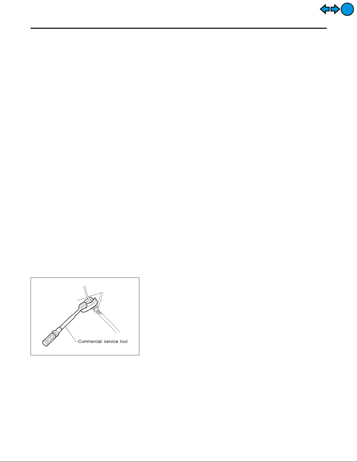
Disassembly
1. Remove piston by turning it counterclockwise with suitable
commercial service tool or long nose pliers.
2. Pry off ring A from piston with suitable pliers and remove
adjusting nut.
NFBR0040
GI
MA
EM
LC
EC
FE
CL
MT
AT
SBR889
SBR088B
3. Disassemble cylinder body.
a. Pry off ring B with suitable pliers, then remove spring cover,
spring and seat.
b. Pry off ring C, then remove key plate, push rod and rod.
c. Remove piston seal.
Be careful not to damage cylinder body.
AX
SU
ST
RS
BT
HA
SC
EL
SBR656
IDX
BR-31

Disassembly (Cont’d)
SBR877
REAR DISC BRAKE
4. Remove return spring, toggle lever and cable guide.
EXIT
EXIT
Inspection
CALIPER
NFBR0041
NFBR0041S01
CAUTION:
Use brake fluid to clean cylinder. Never use mineral oil.
Cylinder Body
NFBR0041S0101
I Check inside surface of cylinder for score, rust, wear, damage
or presence of foreign materials. If any of the above conditions
are observed, replace cylinder body.
I Minor damage from rust or foreign materials may be eliminated
by polishing surface with a fine emery paper.
Replace cylinder body if necessary.
Torque Member
NFBR0041S0102
Check for wear, cracks or other damage. Replace if necessary.
Piston
NFBR0041S0103
CAUTION:
Piston sliding surface is plated. Do not polish with emery
paper even if rust or foreign matter is stuck to sliding surface.
Check piston for score, rust, wear, damage or presence of foreign
materials.
Replace if any of the above conditions are observed.
Pin and Pin Boot
NFBR0041S0104
Check for wear, cracks or other damage.
Replace if any of the above conditions are observed.
SBR219C
ROTOR
Rubbing Surface
NFBR0041S02
NFBR0041S0201
Check rotor for roughness, cracks or chips.
Runout
NFBR0041S0202
1. Secure rotor to wheel hub with two nuts (M12 x 1.25).
2. Check runout using a dial indicator.
Make sure that axial end play is within the specifications
before measuring. Refer to AX section (“REAR WHEEL
BEARING”, “On-vehicle Service”).
BR-32

REAR DISC BRAKE
Inspection (Cont’d)
3. Change relative positions of rotor and wheel hub so that runout
is minimized.
Maximum runout:
0.07 mm (0.0028 in)
GI
EXIT
EXIT
Thickness
Rotor repair limit:
Standard thickness
9 mm (0.35 in)
Minimum thickness
8 mm (0.31 in)
Thickness variation (At least 8 portions)
Maximum 0.02 mm (0.0008 in)
Assembly
1. Insert cam with depression facing towards open end of cylinder.
NFBR0041S0203
NFBR0042
MA
EM
LC
EC
FE
CL
MT
AT
AX
SBR247B
SBR248B
2. Generously apply rubber grease to strut and push rod to make
insertion easy.
3. Fit push rod into square hole in key plate. Also match convex
portion of key plate with concave portion of cylinder.
SU
ST
RS
BT
HA
SC
EL
IDX
SBR893
BR-33

Assembly (Cont’d)
SBR878
REAR DISC BRAKE
4. Install ring C with a suitable tool.
5. Install seat, spring, spring cover and ring B with suitable press
and drift.
EXIT
EXIT
SBR869C
SBR879
SBR892
6. Install cup in the specified direction.
7. Install cup, adjuster, bearing, spacers, washers and ring Awith
a suitable tool.
SBR100B
BR-34

REAR DISC BRAKE
Assembly (Cont’d)
8. Insert piston seal into groove on cylinder body.
9. With piston boot fitted to piston, insert piston boot into groove
on cylinder body and fit piston by turning it clockwise with long
nose pilers, or suitable tool.
GI
MA
EM
EXIT
EXIT
SBR646
SBR868C
SBR027D
LC
EC
FE
CL
MT
10. Fit toggle lever, return spring and cable guide.
AT
AX
SU
11. Adjust the piston to the right angle as shown in the figure.
ST
SBR306E
SBR307E
Installation
CAUTION:
I Refill with new brake fluid “DOT 3”.
I Never reuse drained brake fluid.
1. Install caliper assembly.
I As shown in the figure, align the piston’s concave to the pad’s
convex, then install the cylinder body to the torque member.
2. Install brake hose to caliper securely.
3. Install all parts and secure all bolts.
4. Bleed air. Refer to “Bleeding Brake System”, BR-9.
NFBR0043
BR-35
RS
BT
HA
SC
EL
IDX

Installation (Cont’d)
SBR559E
REAR DISC BRAKE
CAUTION:
The pad retainer is built so the pad returns to its original
position. Be careful to install the pad so the pad-return lever
is against the inner side of the pad, as shown in the left figure.
EXIT
EXIT
BR-36

PARKING BRAKE CONTROL
Components
EXIT
EXIT
Components
Removal and Installation
1. To remove parking brake cable, first remove center console.
2. Disconnect warning switch connector.
3. Remove bolts, slacken off and remove adjusting nut.
4. Remove lock plate and disconnect cable.
NFBR0044
SBR550E
NFBR0045
GI
MA
EM
LC
EC
FE
CL
MT
AT
AX
SBR025D
Inspection
1. Check control lever for wear or other damage. Replace if necessary.
2. Check wires for discontinuity or deterioration. Replace if necessary.
3. Check warning lamp and switch. Replace if necessary.
4. Check parts at each connecting portion and, if found deformed
or damaged, replace.
NFBR0046
SU
ST
RS
BT
HA
SC
EL
IDX
BR-37

Adjustment
PARKING BRAKE CONTROL
EXIT
EXIT
SBR264B
Adjustment
=NFBR0047
Pay attention to the following points after adjustment.
1) There is no drag when control lever is being released.
2) Besure that toggle lever returns to stopper when parking brake
lever is released.
1. Loosen parking brake cable.
2. Depress brake pedal fully more than five times.
3. Operate control lever 10 times or more with a full stroke [203.5
mm (8.01 in)].
4. Adjust control lever or pedal by turning adjusting nut.
5. Pull control lever with specified amount of force. Check lever
stroke and ensure smooth operation.
Number of notches:
10 - 11 [196 N (20 kg, 44 lb)]
6. Bend warning lamp switch plate. Warning lamp should come
on when lever is pulled “A” notches. It should go off when the
lever is fully released.
Number of “A” notches: 1
BR-38

DESCRIPTION
ABS/TCS
Purpose
EXIT
EXIT
Purpose
The ABS consists of electronic and hydraulic components. It allows for control of braking force so that locking of the wheels can be avoided.
The ABS:
1) Ensures proper tracking performance through steering wheel operation.
2) Enables obstacles to be avoided through steering wheel operation.
3) Ensures vehicle stability by preventing flat spins.
ABS (Anti-Lock Brake System) Operation
I When the vehicle speed is less than 10 km/h (6 MPH) this system does not work.
I The Anti-Lock Brake System (ABS) has self-test capabilities. The system turns on the ABS warning lamp
for 1 second after turning the ignition switch ON.The system performs another test the firsttime the vehicle
reaches 6 km/h (4 MPH). A mechanical noise may be heard as the ABS performs a self-test. This is a
normal part of the self-test feature. If a malfunction is found during this check, the ABS warning lamp will
come on.
I During ABS operation, a mechanical noise may be heard. This is a normal condition.
ABS Hydraulic Circuit
NFBR0048
NFBR0049
NFBR0050
GI
MA
EM
LC
EC
FE
CL
MT
1. Inlet solenoid valve
2. Outlet solenoid valve
3. Reservoir
4. Pump
5. Motor
6. Inlet valve
7. Outlet valve
8. Bypass check valve
9. Damper
SBR984D
AT
AX
SU
ST
RS
BT
HA
SC
EL
BR-39
IDX

TCS (Traction Control System) Operation
DESCRIPTION
ABS/TCS
EXIT
EXIT
TCS (Traction Control System) Operation
=NFBR0081
I This system is designed to limit wheel slip during acceleration by cutting fuel to selected cylinders and
changing transmission shift schedule.
The ABS/TCS control unit monitors wheel speed slips through the ABS wheel sensors and determines the
desired torque reduction needed to minimize wheel spin.
The torque reduction by the ABS/TCS control unit may result in a combination of fuel cutoff and change
shift timing of the transmission.
The torque reduction is sent from the ABS/TCS control unit through the data link to the ECM and TCM.
The ECM will cut off fuel and/or TCM change shift schedule to achieve torque reduction.
The TCS will be enabled when the TCS switch is in the ON position (TCS OFF indicator not illuminated),
and if the catalytic converter temperature is within normal operating range.
I This system has a self-diagnostic function. When the ignition switch is initially turned “ON”, the SLIP indi-
cator lamp and TCS OFF indicator lamp light. If there is no problem with the ABS and TCS, both indicator lamps will go out as soon as the engine starts.
I The TCS OFF switch cancels the TCS function. The TCS OFF indicator lamp then lights to indicate that
the TCS is not operating.
I This system utilizes a fuel-cut function to control drive torque. If fuel cut continues for an extended period
of time during high-speed operations, the catalyst may melt and deteriorate. During continued TCS
operations, the system will sometimes suspend the drive torque control function, preventing catalyst melting and deterioration.
System Components
NFBR0051
SBR124B
SBR342E
System Description
SENSOR
NFBR0052
NFBR0052S01
The sensor unit consists of a gear-shaped sensor rotor and a sensor element. The element contains a bar magnet around which a
coil is wound. The sensor is installed on the back side of the brake
rotor. Sine-wave current is generated by the sensor as the wheel
rotates. The frequency and voltage increase(s) as the rotating
speed increases.
BR-40

DESCRIPTION
ABS/TCS
System Description (Cont’d)
EXIT
EXIT
SBR529E
SBR530E
SBR531E
Inlet solenoid
valve
CONTROL UNIT
ABS Function
NFBR0052S02
NFBR0052S0201
The control unit computes the wheel rotating speed by the signal
current sent from the sensor. Then it supplies a DC current to the
actuator solenoid valve. It also controls ON-OFF operation of the
valve relay and motor relay. If any electrical malfunction should be
detected in the system, the warning lamp is turned on. In this
condition, the ABS will be deactivated, and the vehicle’s brake
system reverts to normal operation.
TCS Function
NFBR0052S0202
Drive wheel slippage is detected by the 4-wheel rotating speed
signal. When the wheel slip becomes excessive, theTCS operates,
causing the SLIP indicator lamp to flash. And, at the same time, a
fuel-cut signal to be sent to the ECM and a signal requiring a
change in the shift schedule is sent to the TCM. When the TCS
OFF switch is used to cancel TCS function, the TCS OFF indicator lamp will light. (TCS does not activate.) In case of a malfunction in the TCS, both the SLIP indicator lamp and the TCS OFF
indicator lamp will light, while shutting down the TCS system operation. The vehicle will operate in the same way as a vehicle not
equipped with the TCS.
ACTUATOR
NFBR0052S03
The actuator contains:
I An electric motor and pump
I Two relays
I Eight solenoid valves, each inlet and outlet for
— LH front
— RH front
— LH rear
— RH rear
These components control the hydraulic circuit. The ABS control
unit directs the actuator to increase, hold or decrease hydraulic
pressure to all or individual wheels.
ABS Actuator Operation
Outlet solenoid
valve
NFBR0052S0301
GI
MA
EM
LC
EC
FE
CL
MT
AT
AX
SU
ST
RS
Normal brake operation OFF (Open) OFF (Closed)
Pressure hold ON (Closed) OFF (Closed)
ABS operation
Pressure
decrease
Pressure
increase
ON (Closed) ON (Open)
OFF (Open) OFF (Closed)
BR-41
Master cylinder brake fluid pressure is directly transmitted to caliper via the inlet solenoid valve.
Hydraulic circuit is shut off to hold the caliper brake
fluid pressure.
Caliper brake fluid is sent to reservoir via the outlet
solenoid valve. Then it is pushed up to the master
cylinder by pump.
Master cylinder brake fluid pressure is transmitted to
caliper.
BT
HA
SC
EL
IDX

Component Parts and Harness Connector Location
DESCRIPTION
ABS/TCS
Component Parts and Harness Connector
Location
NFBR0053
EXIT
EXIT
BR-42
SBR534E

DESCRIPTION
ABS/TCS
Schematic
EXIT
EXIT
Schematic
NFBR0054
GI
MA
EM
LC
EC
FE
CL
MT
AT
AX
SU
ST
RS
BT
HA
SC
BR-43
EL
IDX
MBR372A

Wiring Diagram — ABS/TCS —
DESCRIPTION
ABS/TCS
EXIT
EXIT
Wiring Diagram — ABS/TCS —
NFBR0055
BR-44
MBR373A

DESCRIPTION
ABS/TCS
Wiring Diagram — ABS/TCS — (Cont’d)
GI
MA
EM
LC
EC
FE
CL
EXIT
EXIT
MT
AT
AX
SU
ST
RS
BT
HA
BR-45
SC
EL
IDX
MBR374A

Wiring Diagram — ABS/TCS — (Cont’d)
DESCRIPTION
ABS/TCS
EXIT
EXIT
BR-46
MBR375A

DESCRIPTION
ABS/TCS
Wiring Diagram — ABS/TCS — (Cont’d)
GI
MA
EM
LC
EC
FE
CL
EXIT
EXIT
MT
AT
AX
SU
ST
RS
BT
HA
BR-47
SC
EL
IDX
MBR376A

Wiring Diagram — ABS/TCS — (Cont’d)
DESCRIPTION
ABS/TCS
EXIT
EXIT
BR-48
SBR560E

ON BOARD DIAGNOSTIC SYSTEM DESCRIPTION
ABS/TCS
Self-diagnosis
EXIT
EXIT
Self-diagnosis
FUNCTION
I When a problem occurs in the ABS, the ABS warning lamp on
the instrument panel comes on. When a problem occurs in the
TCS, the TCS OFF indicator lamp and SLIP indicator lamp on
the instrument panel comes on. To actuate the self-diagnostic
results mode, ground the self-diagnostic (check) terminal
located on “Data link connector”. The location of the malfunction is indicated by the ABS warning lamp or SLIP indicator
lamp flashing.
I Without TCS ...... A self-diagnostic result is indicated by
means of the ABS warning lamp.
I With TCS ......... A self-diagnostic result is indicated by
means of the SLIP indicator lamp.
SELF-DIAGNOSIS PROCEDURE
1. Drive vehicle over 30 km/h (19 MPH) for at least one minute.
2. Turn ignition switch “OFF”.
3. Ground terminal “9” of “Data link connector” with a suitable
harness.
4. Turn ignition switch “ON” while grounding terminal “9”.
Do not depress brake pedal.
Do not start engine.
NFBR0056
NFBR0056S01
NFBR0056S02
GI
MA
EM
LC
EC
FE
CL
MT
AT
AX
SBR535E
SBR536E
5. After 3.0 seconds, the ABS warning lamp or SLIP indicator
lamp starts flashing to indicate the malfunction code No. (See
NOTE.)
6. Verify the location of the malfunction with the malfunction code
chart. Refer to BR-63. Then make the necessary repairs following the diagnostic procedures.
7. After the malfunctions are repaired, erase the malfunction
codes stored in the control unit. Refer to BR-50.
8. Rerun the self-diagnostic results mode to verify that the malfunction codes have been erased.
9. Disconnect the check terminal from the ground. The self-diagnostic results mode is now complete.
10. Check ABS warning lamp, TCS OFF indicator lamp and SLIP
indicator lamp for deactivation after driving vehicle over 30
km/h (19 MPH) for at least one minute.
11. After making certain that ABS warning lamp, TCS OFF indicator lamp and SLIP indicator lamp does not come on, test the
ABS/TCS SELF-DIAGNOSIS in a safe area to verify that it
functions properly.
SU
ST
RS
BT
HA
SC
EL
IDX
SBR535E
BR-49

Self-diagnosis (Cont’d)
ON BOARD DIAGNOSTIC SYSTEM DESCRIPTION
NOTE:
The indication terminates after five minutes.
However,when the ignition switch is turned from “OFF” to “ON”, the
SLIP indication starts flashing again. The TCS OFF indicator lamp
and ABS warning lamp remain lighted.
HOW TO READ SELF-DIAGNOSTIC RESULTS (MALFUNCTION CODES)
1. Determine the code No. by counting the number of times the
ABS warning lamp or SLIP indicator lamp flashes on and off.
2. When several malfunctions occur at one time, up to three code
numbers can be stored; the latest malfunction will be indicated
first.
3. The indication begins with the start code 12. After that a maximum of three code numbers appear in the order of the latest
one first. The indication then returns to the start code 12 to
repeat (the indication will stay on for five minutes at the most).
4. The malfunction code chart is given on the BR-63 page.
ABS/TCS
NFBR0056S03
EXIT
EXIT
SBR631D
SBR457D
HOW TO ERASE SELF-DIAGNOSTIC RESULTS (MALFUNCTION CODES)
1. Under the self-diagnostic results mode, the malfunction
memory erase mode starts when the check terminal is disconnected from the ground.
2. The self-diagnostic results (malfunction codes) can be erased
by grounding the check terminal more than three times in succession within 12.5 seconds afterthe erase mode starts. (Each
grounding must be longer than one second.)
The ABS warning lamp or SLIP indicator lamp stays on while
the self-diagnosis is in the erase mode, and goes out after the
erase operation has been completed.
3. The self-diagnosis is also completed at the same time. (Refer
to BR-49.)
After the erase operation is completed, it is necessary to rerun
the self-diagnostic mode to verify that malfunction codes no
longer appear. Only the start code (12) should be indicated
when erase operation is completed and system is functioning
normally.
NOTE:
The TCS OFF indicator lamp and ABS warning lamp remain
lighted.
NFBR0056S04
BR-50

ON BOARD DIAGNOSTIC SYSTEM DESCRIPTION
ABS/TCS
CONSULT-II
EXIT
EXIT
CONSULT-II
CONSULT-II APPLICATION TO ABS/TCS
ITEM
Front right wheel sensor X X —
Front left wheel sensor X X —
Rear right wheel sensor X X —
Rear left wheel sensor X X —
ABS sensor X — —
Stop lamp switch — X —
Front right inlet solenoid valve X X X
Front right outlet solenoid valve X X X
Front left inlet solenoid valve X X X
Front left outlet solenoid valve X X X
Rear right inlet solenoid valve X X X
Rear right outlet solenoid valve X X X
Rear left inlet solenoid valve X X X
Rear left outlet solenoid valve X X X
SELF-DIAGNOSTIC
RESULTS
DATA MONITOR ACTIVE TEST
NFBR0057
NFBR0057S01
GI
MA
EM
LC
EC
FE
CL
MT
AT
Actuator solenoid valve relay X X —
Actuator motor relay
(ABS MOTOR is shown on the ACTIVE TEST
screen.)
ABS warning lamp — X —
Battery voltage X X —
Control unit X — —
Engine speed signal — X —
ABS motor X — X
A/T gear position signal — X —
TCS OFF indicator lamp — X —
SLIP indicator lamp — X —
ECM X — —
LAN signal X — —
X: Applicable
—: Not applicable
ECU (ABS CONTROL UNIT) PART NUMBER MODE
XXX
NFBR0057S02
Ignore the ECU part number displayed in the ECU PART NUMBER MODE. Refer to parts catalog to order
the ECU.
AX
SU
ST
RS
BT
HA
SC
EL
BR-51
IDX

ON BOARD DIAGNOSTIC SYSTEM DESCRIPTION
CONSULT-II Inspection Procedure
ABS/TCS
EXIT
EXIT
SBR535E
PBR455D
CONSULT-II Inspection Procedure
SELF-DIAGNOSIS PROCEDURE
NFBR0058
NFBR0058S01
1. Turn ignition switch OFF.
2. Connect CONSULT-II to Data Link Connector.
3. Start engine.
4. Drive vehicle over 30 km/h (19 MPH) for at least one minute.
5. Stop vehicle with engine running and touch “START” on CONSULT-II screen.
6. Touch “ABS”.
PBR385C
PST412B
SBR561E
7. Touch “SELF DIAGNOSIS”.
I The screen shows the detected malfunction and how many
times the ignition switch has been turned since the malfunction.
8. Make the necessary repairs following the diagnostic procedures.
9. After the malfunctions are repaired, erase the self-diagnostic
results stored in the control unit by touching “ERASE”.
10. Check ABS warning lamp, SLIP indicator lamp, TCS OFF indicator lamp for deactivation after driving vehicle over 30 km/h
(19 MPH) for at least one minute.
NOTE:
“SELF-DIAG RESULTS” screen shows the detected malfunction
and how many times the ignition switch has been turned since the
malfunction.
BR-52

ON BOARD DIAGNOSTIC SYSTEM DESCRIPTION
CONSULT-II Inspection Procedure (Cont’d)
ABS/TCS
EXIT
EXIT
Diagnostic item Diagnostic item is detected when ...
FR RH SENSOR
[OPEN]*1
FR LH SENSOR
[OPEN]*1
RR RH SENSOR
[OPEN]*1
RR LH SENSOR
[OPEN]*1
FR RH SENSOR
[SHORT]*1
FR LH SENSOR
[SHORT]*1
RR RH SENSOR
[SHORT]*1
RR LH SENSOR
[SHORT]*1
ABS SENSOR
[ABNORMAL SIGNAL]
FR RH IN ABS SOL
[OPEN]
FR LH IN ABS SOL
[OPEN]
SELF-DIAGNOSTIC RESULTS MODE
I Circuit for front right wheel sensor is open.
(An abnormally high input voltage is entered.)
I Circuit for front left wheel sensor is open.
(An abnormally high input voltage is entered.)
I Circuit for rear right sensor is open.
(An abnormally high input voltage is entered.)
I Circuit for rear left sensor is open.
(An abnormally high input voltage is entered.)
I Circuit for front right wheel sensor is shorted.
(An abnormally low input voltage is entered.)
I Circuit for front left wheel sensor is shorted.
(An abnormally low input voltage is entered.)
I Circuit for rear right sensor is shorted.
(An abnormally low input voltage is entered.)
I Circuit for rear left sensor is shorted.
(An abnormally low input voltage is entered.)
I Teeth damage on sensor rotor or improper installation of wheel sensor.
(Abnormal wheel sensor signal is entered.)
I Circuit for front right inlet solenoid valve is open.
(An abnormally low output voltage is entered.)
I Circuit for front left inlet solenoid valve is open.
(An abnormally low output voltage is entered.)
=NFBR0058S02
Reference
Page
BR-65
BR-65
BR-65
BR-65
BR-65
BR-65
BR-65
BR-65
BR-65
BR-68
BR-68
GI
MA
EM
LC
EC
FE
CL
MT
AT
AX
RR RH IN ABS SOL
[OPEN]
RR LH IN ABS SOL
[OPEN]
FR RH IN ABS SOL
[SHORT]
FR LH IN ABS SOL
[SHORT]
RR RH IN ABS SOL
[SHORT]
RR LH IN ABS SOL
[SHORT]
FR RH OUT ABS SOL
[OPEN]
FR LH OUT ABS SOL
[OPEN]
RR RH OUT ABS SOL
[OPEN]
RR LH OUT ABS SOL
[OPEN]
FR RH OUT ABS SOL
[SHORT]
I Circuit for rear right inlet solenoid valve is open.
(An abnormally low output voltage is entered.)
I Circuit for rear left inlet solenoid valve is open.
(An abnormally low output voltage is entered.)
I Circuit for front right inlet solenoid valve is shorted.
(An abnormally high output voltage is entered.)
I Circuit for front left inlet solenoid valve is shorted.
(An abnormally high output voltage is entered.)
I Circuit for rear right inlet solenoid valve is shorted.
(An abnormally high output voltage is entered.)
I Circuit for rear left inlet solenoid valve is shorted.
(An abnormally high output voltage is entered.)
I Circuit for front right outlet solenoid valve is open.
(An abnormally low output voltage is entered.)
I Circuit for front left outlet solenoid valve is open.
(An abnormally low output voltage is entered.)
I Circuit for rear right outlet solenoid valve is open.
(An abnormally low output voltage is entered.)
I Circuit for rear left outlet solenoid valve is open.
(An abnormally low output voltage is entered.)
I Circuit for front right outlet solenoid valve is shorted.
(An abnormally high output voltage is entered.)
BR-68
BR-68
BR-68
BR-68
BR-68
BR-68
BR-68
BR-68
BR-68
BR-68
BR-68
SU
ST
RS
BT
HA
SC
EL
IDX
FR LH OUT ABS SOL
[SHORT]
I Circuit for front left outlet solenoid valve is shorted.
(An abnormally high output voltage is entered.)
BR-53
BR-68

ON BOARD DIAGNOSTIC SYSTEM DESCRIPTION
CONSULT-II Inspection Procedure (Cont’d)
ABS/TCS
EXIT
EXIT
Diagnostic item Diagnostic item is detected when ...
RR RH OUT ABS SOL
[SHORT]
RR LH OUT ABS SOL
[SHORT]
ABS ACTUATOR RELAY
[ABNORMAL]
ABS MOTOR
[ABNORMAL]
BATTERY VOLTAGE
[ABNORMAL]
CONTROL UNIT I Function of calculation in ABS control unit has failed. BR-86
LAN SIGNAL 1
[ABNORMAL]
LAN SIGNAL 2
[ABNORMAL]
LAN SIGNAL 3
[ABNORMAL]
ENGINE SPEED SIG
[ABNORMAL]
I Circuit for rear right outlet solenoid valve is shorted.
(An abnormally high output voltage is entered.)
I Circuit for rear left outlet solenoid valve is shorted.
(An abnormally high output voltage is entered.)
I Actuator solenoid valve relay is ON, even control unit sends off signal.
I Actuator solenoid valve relay is OFF, even control unit sends on signal.
I Circuit for actuator motor is open or shorted.
I Actuator motor relay is stuck.
I Power source voltage supplied to ABS control unit is abnormally low. BR-84
I ECM judges that communication signal between ABS/TCS control unit and
ECM is abnormal.
I On the Local Area Network (LAN) between ABS/TCS control unit and ECM,
ECM does not transmit the LAN start signal to ABS/TCS control unit.
I The communication start signal output is not terminated and the ordinary sig-
nals are not entered to ABS/TCS control unit.
I Engine speed signal from ECM is not entered. BR-87
Reference
Page
BR-68
BR-68
BR-72
BR-78
BR-89
BR-91
BR-93
ENGINE CHECK SIGNAL
LAN CIRCUIT 1
[ABNORMAL]
LAN CIRCUIT 2
[ABNORMAL]
*1: Be sure to confirm theABS warning lamp illuminates when the ignition switch is turned ON after repairing the shorted sensor circuit,
but the lamp goes out when driving the vehicle over 30 km/h (19 MPH) for one minute in accordance with SELF-DIAGNOSIS
PROCEDURE.
I Based on the signal from ECM, the ABS/TCS control unit judges that the
engine control system is malfunctioning.
I The communication line between ABS/TCS control unit and ECM is open or
shorted.
I An instantaneous signal interruption occurs repeatedly on the communication
line between ABS/TCS control unit and ECM.
DATA MONITOR PROCEDURE
BR-87
BR-92
BR-92
NFBR0058S03
1. Turn ignition switch OFF.
2. Connect CONSULT-II to data link connector.
3. Turn ignition switch ON.
4. Touch “START” on CONSULT-II screen.
PBR455D
5. Touch “ABS”.
PBR385C
BR-54

ON BOARD DIAGNOSTIC SYSTEM DESCRIPTION
CONSULT-II Inspection Procedure (Cont’d)
6. Touch “DATA MONITOR”.
7. Touch “SETTING” on “SELECT MONITOR ITEM” screen.
8. Touch “LONG TIME” on “SET RECORDING COND” screen.
9. Touch “START” on “SELECT MONITOR ITEM”.
ABS/TCS
GI
MA
EM
EXIT
EXIT
PST412B
PBR455D
PBR385C
ACTIVE TEST PROCEDURE
I When conducting Active test, vehicle must be stationary.
I When ABS warning lamp or SLIP indicator lamp stays on,
never conduct Active test.
1. Turn ignition switch OFF.
2. Connect CONSULT-II to Data Link Connector.
3. Start engine.
4. Touch “START” on CONSULT-II screen.
5. Touch “ABS”.
6. Touch “ACTIVE TEST”.
NFBR0058S04
LC
EC
FE
CL
MT
AT
AX
SU
ST
PST412B
PBR976C
7. Select active test item by touching screen.
BR-55
RS
BT
HA
SC
EL
IDX

ON BOARD DIAGNOSTIC SYSTEM DESCRIPTION
CONSULT-II Inspection Procedure (Cont’d)
8. Touch “START”.
9. Carry out the active test by touching screen key.
PBR934C
DATA MONITOR MODE
MONITOR ITEM CONDITION SPECIFICATION
FR RH SENSOR
FR LH SENSOR
RR RH SENSOR
RR LH SENSOR
Drive vehicle.
(Each wheel is rotating.)
Displays computed vehicle speed from wheel sensor signal.
Almost the same speed as speedometer.
ABS/TCS
NFBR0058S05
EXIT
EXIT
STOP LAMP SW
ENGINE SPEED Engine is running. (rpm) Engine speed: 0 - 8,000 (rpm)
FR RH IN SOL
FR RH OUT SOL
FR LH IN SOL
FR LH OUT SOL
RR IN SOL
RR OUT SOL
RL IN SOL
RL OUT SOL
ACTUATOR RLY
MOTOR RELAY
WARNING LAMP
BATTERY VOLT Power supply voltage for control unit
THRTL OPENING
TRQ RDUC SIG
Turn ignition switch ON and
depress brake pedal.
Ignition switch is turned ON or
engine is running.
Ignition switch is turned ON or
engine is running.
The throttle valve opening rate
(%)
The operating cylinder ratio to
fuel injected, calculated and
sent by ABS/TCS control unit
to ECM, is displayed.
Depress the pedal: ON
Release the pedal: OFF
Operating conditions for each solenoid valve are indicated.
ABS is not operating: OFF
Displays ON/OFF condition of ABS actuator relay.
When turning ignition switch ON, ABS actuator relay is operated.
ABS is not operating: OFF
ABS is operating: ON
Warning lamp is turned on: ON
Warning lamp is turned off: OFF
Opening rate: 0 - 100%
TCS is not operating: 0
TCS is operating:0-6*
* Displays the number of cylinders to which fuel supply is cut.
GEAR
TCS SW
TCS OFF LAMP
A/T gear position signal
detected by TCM via ECM is
displayed.
ON/OFF condition of signal
from TCS switch is displayed.
I TCS OFF condition is dis-
played.
I The condition of malfunction-
ing TCS is displayed.
BR-56
Gear position: P, N: N.P
1st: 1
2nd: 2
3rd: 3
4th: 4
TCS OFF S/W (all the time switch is pressed): ON
TCS OFF S/W (released): OFF
TCS OFF indicator “OFF”: OFF
TCS OFF indicator “ON”: ON

ON BOARD DIAGNOSTIC SYSTEM DESCRIPTION
MONITOR ITEM CONDITION SPECIFICATION
ABS/TCS
CONSULT-II Inspection Procedure (Cont’d)
EXIT
EXIT
The TCS functioning state is
SLIP LAMP
TCS OPR SIG TCS operating condition
displayed by detecting rear
wheel slip.
SLIP indicator “ON”: ON
SLIP indicator “OFF”: OFF
TCS is not operating: OFF
TCS is operating: ON
ACTIVE TEST MODE
TEST ITEM CONDITION JUDGEMENT
Brake fluid pressure control operation
FR RH SOLENOID
FR LH SOLENOID
RR RH SOLENOID
RR LH SOLENOID
ABS MOTOR
NOTE:
Active test will automatically stop ten seconds after the test starts. (TEST IS STOPPED monitor shows ON.)
Ignition switch is turned ON.
UP (Increase): OFF OFF
KEEP (Hold): ON OFF
DOWN (Decrease): ON ON
ABS actuator motor
ON: Motor runs
OFF: Motor stops
NFBR0058S06
IN SOL OUT SOL
GI
MA
EM
LC
EC
FE
CL
MT
AT
AX
SU
ST
RS
BT
HA
SC
EL
BR-57
IDX

TROUBLE DIAGNOSIS — INTRODUCTION
How to Perform Trouble Diagnoses for Quick and Accurate Repair
How to Perform Trouble Diagnoses for Quick
and Accurate Repair
INTRODUCTION
TheABS/TCS system has an electronic control unit to controlmajor
functions. The control unit accepts input signals from sensors and
instantly drives actuator. It is essential that both kinds of signals are
proper and stable. It is also important to check for conventional
problems: such as air leaks in the booster or lines, lack of brake
fluid, or other problems with the brake system.
It is much more difficult to diagnose a problem that occurs intermit-
SEF233G
SEF234G
tently rather than continuously. Most intermittent problems are
caused by poor electric connections or faulty wiring. In this case,
careful checking of suspicious circuits may help prevent the
replacement of good parts.
A visual check only may not find the cause of the problems, so a
road test should be performed.
Before undertaking actual checks, take just a few minutes to talk
with a customer who approaches with a ABS/TCS complaint. The
customer is a very good source of information on such problems;
especially intermittent ones. Through the talks with the customer,
find out what symptoms are present and under what conditions
they occur.
Start your diagnosis by looking for “conventional” problems first.
This is one of the best ways to troubleshoot brake problems on an
ABS/TCS controlled vehicle. Also check related Service Bulletins
for information.
ABS/TCS
NFBR0059
NFBR0059S01
EXIT
EXIT
BR-58

TROUBLE DIAGNOSIS — BASIC INSPECTION
ABS/TCS
Preliminary Check
EXIT
EXIT
Preliminary Check
1 CHECK BRAKE FLUID LEVEL
Check brake fluid level in reservoir tank.
Low fluid level may indicate brake pad wear or leakage from brake line.
Is brake fluid filled between MAX and MIN lines on reservoir tank and/or has brake fluid been contaminated?
Yes © GO TO 2.
No © Repair. GO TO 2.
2 CHECK BRAKE LINE
Check brake line for leakage.
NFBR0060
SBR451D
GI
MA
EM
LC
EC
FE
CL
MT
AT
Is leakage present at or around brake lines, tubes or hoses or are any of these parts cracked or damaged?
Yes © GO TO 3.
No © Repair. GO TO 3.
AX
SU
SBR389C
ST
RS
BT
HA
SC
EL
BR-59
IDX

TROUBLE DIAGNOSIS — BASIC INSPECTION
Preliminary Check (Cont’d)
3 CHECK BRAKE BOOSTER OPERATION
Check brake booster for operation and air tightness.
Refer to BR-21.
Is brake booster airtight and functioning properly?
Yes © GO TO 4.
No © Replace. GO TO 4.
ABS/TCS
SBR058C
EXIT
EXIT
4 CHECK BRAKE PAD AND ROTOR
Check brake pad and rotor.
Refer to BR-24, 26, 28, 32.
Are brake pads and rotors functioning properly?
Yes © GO TO 5.
No © Replace.
SBR059C
BR-60

TROUBLE DIAGNOSIS — BASIC INSPECTION
5 RECHECK BRAKE FLUID LEVEL
Check brake fluid level in reservoir tank again.
ABS/TCS
Preliminary Check (Cont’d)
GI
MA
EM
LC
EXIT
EXIT
Is brake fluid filled between MAX and MIN lines on reservoir tank and/or has brake fluid been contaminated?
Yes © GO TO 6.
No © Fill up brake fluid.
6 CHECK WARNING LAMP ACTIVATION
Check warning lamp activation.
Does warning lamp turn on when ignition switch is turned “ON”?
Yes © GO TO 7.
No © Check fuse, warning lamp bulb and warning lamp circuit.
SBR451D
SBR536E
EC
FE
CL
MT
AT
AX
SU
ST
7 CHECK WARNING LAMP DEACTIVATION
Check warning lamp for deactivation after engine is started.
Does warning lamp turn off when engine is started?
Yes © GO TO 8.
No © Go to Self-diagnosis. Refer to BR-49, 52.
8 DRIVE VEHICLE
Drive vehicle at speeds over 30 km/h (19 MPH) for at least one minute.
Does warning lamp remain off after vehicle has been driven at 30 km/h (19 MPH) for at least one minute?
Yes © END
No © Go to Self-diagnosis. Refer to BR-49, 52.
BR-61
RS
BT
HA
SC
EL
IDX

Ground Circuit Check
TROUBLE DIAGNOSIS — BASIC INSPECTION
ABS/TCS
EXIT
EXIT
SBR792D
SBR714DE
Ground Circuit Check
ACTUATOR MOTOR GROUND
NFBR0061
NFBR0061S01
I Check resistance between actuator motor ground terminal and
body ground.
Resistance: 0Ω
CONTROL UNIT GROUND
NFBR0061S02
I Check resistance between the terminals and ground.
Resistance: 0Ω
ABS SOLENOID VALVE RELAY GROUND
NFBR0061S03
I Check resistance between solenoid valve relay terminal 4 and
ground.
Resistance: 0Ω
SBR764DH
BR-62

TROUBLE DIAGNOSIS — GENERAL DESCRIPTION
Malfunction Code/Symptom Chart
ABS/TCS
EXIT
EXIT
Code No.
(No. of SLIP indicator flashes)
12 Self-diagnosis could not detect any malfunctions OFF OFF OFF — —
21 Front right sensor (open-circuit) ON ON ON X BR-65
22 Front right sensor (short-circuit)*2 ON ON ON X BR-65
25 Front left sensor (open-circuit) ON ON ON X BR-65
26 Front left sensor (short-circuit)*2 ON ON ON X BR-65
31 Rear right sensor (open-circuit) ON ON ON X BR-65
32 Rear right sensor (short-circuit)*2 ON ON ON X BR-65
35 Rear left sensor (open-circuit) ON ON ON X BR-65
36 Rear left sensor (short-circuit)*2 ON ON ON X BR-65
41 Actuator front right outlet solenoid valve ON ON ON X BR-68
42 Actuator front right inlet solenoid valve ON ON ON X BR-68
45 Actuator front left outlet solenoid valve ON ON ON X BR-68
46 Actuator front left inlet solenoid valve ON ON ON X BR-68
Malfunction Code/Symptom Chart
Warn-
Malfunctioning part
ing
lamp
ABS
Indicator
TCS
OFF
SLIP
Failsafe
NFBR0062
Refer-
ence
Page
GI
MA
EM
LC
EC
FE
CL
MT
AT
51 Actuator rear right outlet solenoid valve ON ON ON X BR-68
52 Actuator rear right inlet solenoid valve ON ON ON X BR-68
55 Actuator rear left outlet solenoid valve ON ON ON X BR-68
56 Actuator rear left inlet solenoid valve ON ON ON X BR-68
57 Power supply (Low or high voltage)*3 ON ON OFF —*1 BR-84
61 Actuator motor or motor relay*4 ON ON ON X BR-78
63 Solenoid valve relay ON ON ON X BR-72
71 Control unit ON ON ON*5 X BR-86
98 LAN communication system failure OFF ON ON X BR-92
81 Engine speed signal OFF ON ON X BR-87
96 LAN is monitoring OFF ON ON X BR-89
87 Engine parts are under fail-safe condition OFF ON ON X BR-87
92 LAN communication start procedures are incomplete OFF ON ON X BR-91
94 Continued reception after LAN communication starts OFF ON ON X BR-93
85
ABS works frequently. — ————BR-94
Unexpected pedal action — ————BR-94
ECM determines the ABS/TCS control unit is malfunctioning.
OFF ON ON X BR-89
AX
SU
ST
RS
BT
HA
SC
EL
Long stopping distance — ————BR-95
ABS does not work. — ————BR-96
Pedal vibration and noise — ————BR-97
BR-63
IDX

TROUBLE DIAGNOSIS — GENERAL DESCRIPTION
Malfunction Code/Symptom Chart (Cont’d)
Code No.
(No. of SLIP indicator flashes)
Control unit power supply circuit
SLIP indicator stays on when
engine is running
Warning lamp bulb circuit
Control unit or control unit connector
Solenoid valve relay stuck
Power supply for solenoid valve relay coil
Malfunctioning part
ABS/TCS
Warn-
ing
lamp
ABS
ON ON ON X*6 —
Indicator
TCS
OFF
Failsafe
SLIP
Refer-
ence
Page
EXIT
EXIT
SLIP indicator does not come
on when engine is running
Poor acceleration TCM is the cause of the symptom. OFF OFF OFF — BR-112
X: Available —: Not available
*1: Fail-safe operation does not activate. A signal from control unit suspends TCS and ABS control operation. Brakes operate conven-
tionally. After specified power supply voltage resumes, TCS OFF indicator and ABS warning lamp go out, allowing for TCS and ABS
control operation.
*2: If a wheel or wheels spin on bad or slippery road surfaces for a period of approximately 10 to 80 seconds, the ABS warning lamp
and the TCS OFF indicator lamp light. But this is not a malfunction. When the ignition switch is turned “ON” after a shorted wheel sensor circuit has been repaired, the ABS warning lamp and the TCS OFF indicator lamp light. Drive the vehicle at about 30 km/h (19 MPH)
to ensure these lamps go out within 1 minute.
*3: When the BATTERY VOLTAGE [ABNORMAL] code No. appears on the display, it does not indicate a malfunction related to the
ABS/TCS control unit. Do not replace the ABS/TCS control unit even if the code No. appears.
*4: The BATTERY VOLTAGE [ABNORMAL] code No. can sometimes appear when the ABS motor ground circuit is loose or disconnected. When it does, always check the ground circuit for improper installation.
*5: Only the SLIP indicator lamp goes out depending on the type of ECM malfunction.
*6: If failure occurs in self-diagnostic check terminal (terminal No. 4 of data link connector) circuit and/or TCS operation (SLIP indica-
tor) circuit, fail-safe operation will not activate.
Fuse, warning lamp bulb or warning lamp circuit
Control unit
ON ON ON X —
BR-64

TROUBLE DIAGNOSES FOR SELF-DIAGNOSTIC ITEMS
Wheel Sensor or Rotor
ABS/TCS
EXIT
EXIT
Wheel Sensor or Rotor
DIAGNOSTIC PROCEDURE
Malfunction code No. 21, 22, 25, 26, 31, 32, 35, 36 or 18
NOTE:
Wheel position should be identified by code No. except code No.
18 (sensor rotor).
1 INSPECTION START
Wheel sensor inspection
SBR769DD
© GO TO 2.
2 CHECK CONNECTOR
1. Disconnect connectors from control unit and wheel sensor of malfunction code No. Check terminals for damage or
loose connections. Then reconnect connectors.
2. Carry out self-diagnosis again.
Does warning lamp activate again?
Yes © GO TO 3.
No © INSPECTION END
NFBR0064
NFBR0064S01
GI
MA
EM
LC
EC
FE
CL
MT
AT
AX
SU
BR-65
ST
RS
BT
HA
SC
EL
IDX

TROUBLE DIAGNOSES FOR SELF-DIAGNOSTIC ITEMS
Wheel Sensor or Rotor (Cont’d)
3 CHECK WHEEL SENSOR CIRCUIT
1. Disconnect control unit connector.
2. Check resistance between control unit connector terminals.
Code No. 21 or 22 (Front RH wheel)
Terminals 14 and 15
Code No. 25 or 26 (Front LH wheel)
Terminals 9 and 10
Code No. 31 or 32 (Rear RH wheel)
Terminals 11 and 38
Code No. 35 or 36 (Rear LH wheel)
Terminals 12 and 13
Resistance: 0.8 - 1.85 kΩ
ABS/TCS
EXIT
EXIT
SBR247DI
Is resistance 0.8 - 1.85 kΩ?
Yes © GO TO 5.
No © GO TO 4.
4 CHECK WHEEL SENSOR
Check resistance of each sensor. (See NOTE)
Resistance: 0.8 - 1.85 kΩ
SBR761DE
Is resistance 0.8 - 1.85 kΩ?
Yes © Repair harness and connectors between control unit connector and wheel sensor con-
nector.
No © Replace wheel sensor.
5 CHECK TIRE
Check for inflation pressure, wear and size of each tire.
Are tire pressure and size correct and is tire wear within specifications?
Yes © GO TO 6.
No © Adjust tire pressure or replace tire(s).
BR-66

TROUBLE DIAGNOSES FOR SELF-DIAGNOSTIC ITEMS
6 CHECK WHEEL BEARING
Check wheel bearing axial end play.
Check clearance between sensor and rotor.
Clearance:
Front
0.273 - 0.925 mm (0.0107 - 0.0364 in)
Rear
0.387 - 0.992 mm (0.0152 - 0.0391 in)
ABS/TCS
Wheel Sensor or Rotor (Cont’d)
GI
MA
EM
LC
EC
FE
EXIT
EXIT
SBR605AA
SBR069CA
Is axial end play and clearance within specifications?
Yes © GO TO 7.
No © Clean sensor fixing portion, or replace sensor.
7 CHECK SENSOR ROTOR
Check sensor rotor for teeth damage.
Is sensor rotor free from damage?
Yes © Check control unit pin terminals for damage or the connection of control unit harness
connector. Reconnect control unit harness connector. Then retest.
No © Replace sensor rotor.
CL
MT
AT
AX
SU
ST
RS
BT
BR-67
HA
SC
EL
IDX

TROUBLE DIAGNOSES FOR SELF-DIAGNOSTIC ITEMS
ABS Actuator Solenoid Valve
ABS/TCS
EXIT
EXIT
1 INSPECTION START
ABS actuator solenoid valve inspection
ABS Actuator Solenoid Valve
DIAGNOSTIC PROCEDURE
Malfunction code No. 41, 45, 51, 55, 42, 46, 52, 56
=NFBR0063
NFBR0063S01
SBR334EA
© GO TO 2.
2 CHECK CONNECTOR
1. Disconnect connectors from control unit, ABS actuator and ABS solenoid valve relay. Check terminals for damage or
loose connections. Then reconnect connectors.
2. Carry out self-diagnosis again.
Does warning lamp activate again?
Yes © GO TO 3.
No © INSPECTION END
BR-68

TROUBLE DIAGNOSES FOR SELF-DIAGNOSTIC ITEMS
ABS Actuator Solenoid Valve (Cont’d)
3 CHECK ABS ACTUATOR SOLENOID VALVE
1. Disconnect connectors from control unit and ABS actuator.
2. Check resistance between control unit connector terminals and ABS actuator 2-pin connector E5 (ABS actuator side)
terminals.
ABS/TCS
MTBL0084
GI
MA
EM
LC
EC
FE
CL
EXIT
EXIT
Yes © GO TO 6.
No © GO TO 4.
Is resistance within specifications?
MT
AT
SBR766DH
AX
SU
ST
RS
BT
HA
BR-69
SC
EL
IDX

TROUBLE DIAGNOSES FOR SELF-DIAGNOSTIC ITEMS
ABS Actuator Solenoid Valve (Cont’d)
ABS/TCS
4 CHECK ABS ACTUATOR SOLENOID VALVE
1. Disconnect ABS actuator 8-pin connector.
2. Check resistance between ABS actuator 8-pin connector E127 or E7 (ABS actuator side) terminals and ABS actuator
2-pin connector E5 (ABS actuator side) terminals.
MTBL0085
EXIT
EXIT
Is resistance within specifications?
Yes © Check the following.
I Harness connectors E127 or E7, E5
I Harness for open or short between actuator connector and control unit
I Harness for open or short between actuator 8-pin connector and actuator 2-pin con-
nector
If NG, repair harness or connectors.
No © GO TO 5.
SBR767DG
BR-70

TROUBLE DIAGNOSES FOR SELF-DIAGNOSTIC ITEMS
5 CHECK ABS ACTUATOR SOLENOID VALVE
Check resistance between solenoid valve terminals 1, 3, 5, 7, 14, 15, 16, 17.
Is resistance within specifications?
Yes © Check the following.
I Harness connectors E127 or E7, E5
I Harness for open or short between actuator connector and control unit
I Harness for open or short between actuator 8-pin connector and actuator 2-pin con-
nector
If NG, repair harness or connectors.
No © Replace ABS actuator.
ABS/TCS
ABS Actuator Solenoid Valve (Cont’d)
MTBL0086
GI
MA
EM
LC
EC
FE
CL
MT
AT
EXIT
EXIT
6 CHECK ABS ACTUATOR SOLENOID VALVE RELAY
1. Remove solenoid valve relay.
2. Check continuity between ABS actuator 2-pin connector E18 (body side) terminal 19 and solenoid valve relay terminal
3.
Continuity should exist.
SBR768DG
Does continuity exist?
Yes © Go to “Solenoid Valve Relay”, BR-72.
No © Check the following.
I Harness connectors E118 or E33, E5
I Harness for open or short between actuator connector and solenoid valve relay termi-
nal (relay box side)
If NG, repair harness or connectors.
AX
SU
ST
RS
BT
HA
SC
EL
BR-71
IDX

TROUBLE DIAGNOSES FOR SELF-DIAGNOSTIC ITEMS
Solenoid Valve Relay
ABS/TCS
EXIT
EXIT
1 INSPECTION START
Solenoid valve relay inspection
Solenoid Valve Relay
DIAGNOSTIC PROCEDURE
Malfunction code No. 63
NFBR0066
NFBR0066S01
SBR334EA
© GO TO 2.
2 CHECK SOLENOID VALVE POWER SUPPLY CIRCUIT
Check 40A [e] fusible link (ABS ACTR) for ABS solenoid valve relay. For fusible link layout, refer to POWER SUPPLY
ROUTING in EL section.
Is fusible link OK?
Yes © GO TO 3.
No © GO TO 9.
3 CHECK FUSE
Check 10A fuse No. 30. For fuse layout, refer to “POWER SUPPLY ROUTING” in EL section.
Is fuse OK?
Yes © GO TO 4.
No © GO TO 13.
4 CHECK CONNECTOR
1. Disconnect connectors from control unit and ABS actuator. Check terminals for damage or loose connection. Then
reconnect connectors.
2. Carry out self-diagnosis again.
Does warning lamp activate again?
Yes © GO TO 5.
No © INSPECTION END
BR-72

TROUBLE DIAGNOSES FOR SELF-DIAGNOSTIC ITEMS
Solenoid Valve Relay (Cont’d)
5 CHECK GROUND CIRCUIT
Refer to CONTROL UNIT GROUND and ACTUATOR MOTOR GROUND in Ground Circuit Check, BR-62.
Is ground circuit OK?
Yes © GO TO 6.
No © Repair harness and connectors.
ABS/TCS
GI
MA
EXIT
EXIT
6 CHECK SOLENOID VALVE POWER SUPPLY CIRCUIT
1. Remove solenoid valve relay.
2. Check voltage between solenoid valve relay terminal 5 and ground.
Does battery voltage exist?
Yes © GO TO 7.
No © Check the following.
I Harness connector E118 or E33
I Harness for open or short between solenoid valve terminal (relay box side) and fusible
link
If NG, repair harness or connectors.
SBR777DH
EM
LC
EC
FE
CL
MT
AT
AX
SU
BR-73
ST
RS
BT
HA
SC
EL
IDX

TROUBLE DIAGNOSES FOR SELF-DIAGNOSTIC ITEMS
Solenoid Valve Relay (Cont’d)
7 CHECK CIRCUIT
1. Disconnect control unit connector.
2. Check continuity between control unit connector terminals and solenoid valve relay terminals.
ABS/TCS
MTBL0089
EXIT
EXIT
Does continuity exist?
Yes © GO TO 8.
NG © Check the following.
I Harness connector E9 or E91
I Harness for open or short between solenoid valve relay terminal (relay box side) and
control unit
If NG, repair harness or connectors.
SBR778DG
BR-74

TROUBLE DIAGNOSES FOR SELF-DIAGNOSTIC ITEMS
8 CHECK SOLENOID VALVE RELAY
ABS/TCS
Solenoid Valve Relay (Cont’d)
GI
MA
EM
EXIT
EXIT
While applying battery voltage to relay terminals, insert fuse into the circuit.
Is solenoid valve relay OK?
Yes © Go to “ABS Actuator Solenoid Valve”, BR-68.
No © Replace solenoid valve relay.
9 REPLACE FUSIBLE LINK
Replace fusible link.
Does the fusible link blow out when ignition switch is turned “ON”?
Yes © GO TO 10.
No © INSPECTION END
MTBL0090
SBR776D
LC
EC
FE
CL
MT
AT
AX
SU
ST
BR-75
RS
BT
HA
SC
EL
IDX

TROUBLE DIAGNOSES FOR SELF-DIAGNOSTIC ITEMS
Solenoid Valve Relay (Cont’d)
10 CHECK RELAY UNIT POWER SUPPLY CIRCUIT
1. Remove solenoid valve relay.
2. Check continuity between solenoid valve relay terminal 5 and ground.
Does continuity exist?
Yes © GO TO 11.
No © Check the following.
I Harness connector E118 or E33
I Harness for open or short between solenoid valve terminal (relay box side) and fusible
link
If NG, repair harness or connectors.
ABS/TCS
SBR779DH
EXIT
EXIT
11 CHECK ABS SOLENOID VALVE RELAY
1. Disconnect ABS actuator 2-pin connectors and control unit connector.
2. Check continuity between ABS actuator 2-pin connector E5 (body side) terminal 19 and ground.
Does continuity exist?
Yes © Replace ABS relay box.
No © GO TO 12.
SBR493DH
BR-76

TROUBLE DIAGNOSES FOR SELF-DIAGNOSTIC ITEMS
Solenoid Valve Relay (Cont’d)
12 CHECK ABS SOLENOID VALVE
Check continuity between ABS actuator 2-pin connector E5 (ABS actuator side) terminal 19 and ground.
ABS/TCS
GI
MA
EM
LC
EXIT
EXIT
Does continuity exist?
Yes © Replace ABS actuator.
No © Go to “ABS Actuator Solenoid Valve”, BR-68.
13 REPLACE FUSE
Replace fuse.
Does the fuse blow out when ignition switch is turned “ON”?
Yes © Check the following.
I Harness connector E9 or E91
I Harness for open or short between ABS control unit connector and fuse
If NG, repair harness or connectors.
NG © INSPECTION END
SBR494DH
EC
FE
CL
MT
AT
AX
SU
ST
BR-77
RS
BT
HA
SC
EL
IDX

TROUBLE DIAGNOSES FOR SELF-DIAGNOSTIC ITEMS
Motor Relay or Motor
ABS/TCS
EXIT
EXIT
1 INSPECTION START
ABS motor relay inspection
Motor Relay or Motor
DIAGNOSTIC PROCEDURE
Malfunction code No. 61
=NFBR0065
NFBR0065S01
SBR335EA
© GO TO 2.
2 CHECK MOTOR POWER SUPPLY CIRCUIT
Check 40A [d] fusible link (ABS MTR) for ABS motor relay. For fusible link layout, refer to POWER SUPPLY ROUTING in
EL section.
Is fusible link OK?
Yes © GO TO 3.
No © GO TO 10.
3 CHECK CONNECTOR
1. Disconnect connectors from control unit and ABS actuator. Check terminals for damage or loose connection. Then
reconnect connectors.
2. Carry out self-diagnosis again.
Does warning lamp activate again?
Yes © GO TO 4.
No © INSPECTION END
BR-78

TROUBLE DIAGNOSES FOR SELF-DIAGNOSTIC ITEMS
4 CHECK ABS RELAY UNIT POWER SUPPLY CIRCUIT
1. Remove motor relay.
2. Check voltage between motor relay terminal 5 and ground.
ABS/TCS
Motor Relay or Motor (Cont’d)
GI
MA
EM
LC
EXIT
EXIT
Does battery voltage exist?
Yes © GO TO 5.
No © Check the following.
I Harness connector E119 or E29
I Harness for open or short between motor relay terminal (relay box side) and fusible
link
If NG, repair harness or connectors.
SBR771DH
EC
FE
CL
MT
AT
AX
SU
ST
BR-79
RS
BT
HA
SC
EL
IDX

TROUBLE DIAGNOSES FOR SELF-DIAGNOSTIC ITEMS
Motor Relay or Motor (Cont’d)
5 CHECK CIRCUIT
1. Disconnect control unit connector.
2. Check continuity between control unit connector terminals and motor relay terminals.
ABS/TCS
MTBL0087
EXIT
EXIT
Does continuity exist?
Yes © GO TO 6.
No © Check the following.
I Harness connectors E119 or E29, E9 or E91
I Harness for open or short between motor relay terminal (relay box side) and control
unit
If NG, repair harness or connectors.
SBR772DG
BR-80

TROUBLE DIAGNOSES FOR SELF-DIAGNOSTIC ITEMS
6 CHECK MOTOR RELAY
ABS/TCS
Motor Relay or Motor (Cont’d)
GI
MA
EM
EXIT
EXIT
While applying battery voltage to relay terminals, insert fuse into the circuit.
Is motor relay OK?
Yes © GO TO 7.
No © Replace motor relay.
7 CHECK ACTUATOR MOTOR GROUND CIRCUIT
Refer to ACTUATOR MOTOR GROUND in Ground Circuit Check, BR-62.
Is ground circuit OK?
Yes © GO TO 8.
No © Check the following.
I Harness connector E119 or E29
I Harness for open or short between solenoid valve relay terminal (relay box side) and
ground
If NG, repair harness or connectors.
MTBL0088
SBR776D
LC
EC
FE
CL
MT
AT
AX
SU
ST
RS
BR-81
BT
HA
SC
EL
IDX

TROUBLE DIAGNOSES FOR SELF-DIAGNOSTIC ITEMS
Motor Relay or Motor (Cont’d)
ABS/TCS
8 CHECK ABS ACTUATOR CIRCUIT
Check continuity between ABS actuator 2-pin connector E5 (ABS actuator side) terminal 21 and actuator motor ground
terminal.
Does continuity exist?
Yes © GO TO 9.
No © Check the following.
I Harness connector E5
I Harness for open or short between actuator connector and motor terminal
If NG, repair harness or connectors.
SBR793DF
EXIT
EXIT
9 CHECK MOTOR
1. Remove motor relay.
2. Connect actuator connectors.
3. Connect suitable wire between motor relay connector terminals 3 and 5.
Do not connect wire for more than 5 seconds.
Does motor operate?
Yes © Go to “Low Voltage”, BR-84.
No © Replace ABS actuator.
10 REPLACE FUSIBLE LINK
Replace fusible link.
Does the fusible link blow out when ignition switch is turned “ON”?
Yes © GO TO 11.
No © INSPECTION END
SBR773DH
BR-82

TROUBLE DIAGNOSES FOR SELF-DIAGNOSTIC ITEMS
11 CHECK MOTOR POWER SUPPLY CIRCUIT
1. Remove motor relay.
2. Check continuity between motor relay terminal 5 and ground.
ABS/TCS
Motor Relay or Motor (Cont’d)
GI
MA
EM
LC
EXIT
EXIT
Does continuity exist?
Yes © GO TO 12.
No © Check the following.
I Harness connector E119 or E29
I Harness for open or short between motor relay terminal (relay box side) and fusible
link
If NG, repair harness or connectors.
12 CHECK ABS MOTOR RELAY
1. Disconnect control unit connector.
2. Check continuity between motor relay terminal 3 and ground.
Does continuity exist?
Yes © Check the following.
I Harness connector E119 or E29
I Harness for open or short between motor relay terminal (relay box side) and fusible
link
If NG, repair harness or connectors.
No © GO TO 13.
SBR774DH
SBR775DI
EC
FE
CL
MT
AT
AX
SU
ST
RS
BT
HA
BR-83
SC
EL
IDX

TROUBLE DIAGNOSES FOR SELF-DIAGNOSTIC ITEMS
Motor Relay or Motor (Cont’d)
ABS/TCS
13 CHECK ABS MOTOR POWER SUPPLY CIRCUIT
1. Remove motor ground.
2. Check continuity between ABS actuator 2-pin connector E5 (ABS actuator side) terminal 21 and ground.
Does continuity exist?
Yes © Replace ABS actuator.
No © GO TO 14.
14 CHECK MOTOR
Go to “9 CHECK MOTOR” in “Motor Relay or Motor” (preceding page).
Does motor operate?
Yes © Check control unit pin terminals for damage or the connection of control unit harness
connector. Reconnect control unit harness connector. Then retest.
No © Replace ABS actuator.
SBR489DH
EXIT
EXIT
Low Voltage
DIAGNOSTIC PROCEDURE
Malfunction code No. 57
1 INSPECTION START
ABS control unit power supply and ground circuit inspection
© GO TO 2.
BR-84
NFBR0067
NFBR0067S01
SBR337EA

TROUBLE DIAGNOSES FOR SELF-DIAGNOSTIC ITEMS
Low Voltage (Cont’d)
2 CHECK CONNECTOR
1. Disconnect control unit connectors. Check terminals for damage or loose connections. Then reconnect connectors.
2. Carry out self-diagnosis again.
Does warning lamp activate again?
Yes © GO TO 3.
No © INSPECTION END
3 CHECK ABS CONTROL UNIT POWER SUPPLY
1. Disconnect control unit connector.
2. Check voltage between control unit connector terminal 1 and ground.
ABS/TCS
GI
MA
EM
LC
EC
FE
CL
EXIT
EXIT
SBR726DE
Does battery voltage exist when ignition switch is turned ON?
Yes © GO TO 4.
No © GO TO 5.
4 CHECK CONTROL UNIT GROUND
Refer to CONTROL UNIT GROUND in Ground Circuit Check, BR-62.
Is ground circuit OK?
OK © Check control unit pin terminals for damage or the connection of control unit harness
connector. Reconnect control unit harness connector. Then retest.
NG © Check the following.
I Harness connector E9 or E91
I Harness for open or short between control unit and ground
If NG, repair harness or connectors.
5 CHECK FUSE
Check 10A fuse 31 (Engine control) for control unit. Refer to POWER SUPPLY ROUTING in EL section.
Is fuse OK?
Yes © GO TO 6.
No © Replace fuse.
MT
AT
AX
SU
ST
RS
BT
HA
SC
6 CHECK ABS CONTROL UNIT POWER SUPPLY CIRCUIT
Check continuity between battery and control unit connector terminal 1.
Does continuity exist?
Yes © Check battery. Refer to BATTERY in EL section.
No © Check the following.
I Harness connector E9 or E91
I Harness for open or short between control unit and fuse
If NG, repair harness or connectors.
BR-85
EL
IDX

Control Unit
TROUBLE DIAGNOSES FOR SELF-DIAGNOSTIC ITEMS
ABS/TCS
EXIT
EXIT
Control Unit
DIAGNOSTIC PROCEDURE
Malfunction code No. 71
1 INSPECTION START
ABS control unit power supply and ground circuit inspection
© GO TO 2.
2 CHECK CONNECTOR
1. Disconnect control unit connector.
Check terminals for damage or loose connections. Then reconnect connectors.
2. Carry out self-diagnosis again.
Does warning lamp activate again?
Yes © GO TO 3.
No © INSPECTION END
NFBR0068
NFBR0068S01
SBR337EA
3 CHECK ABS CONTROL UNIT POWER SUPPLY CIRCUIT
Check voltage. Refer to “3. CHECK ABS CONTROL UNIT POWER SUPPLY CIRCUIT” in “Low Voltage”, BR-84.
Does battery voltage exist when ignition switch is turned ON?
Yes © GO TO 4.
No © Repair.
4 CHECK WARNING LAMP INDICATION
Does warning lamp indicate code No. 71 again?
Yes © Replace control unit.
No © Inspect the system according to the code No.
BR-86

TROUBLE DIAGNOSES FOR SELF-DIAGNOSTIC ITEMS
ENGINE CHECK SIGNAL — Engine System
TCS
EXIT
EXIT
ENGINE CHECK SIGNAL — Engine System
DIAGNOSTIC PROCEDURE
NFBR0082
NFBR0082S01
Malfunction code No. 87
1 INSPECTION START
Self-diagnostic item “ENGINE CHECK SIGNAL” appears on display.
© GO TO 2.
2 CHECK ENGINE SYSTEM
Perform self-diagnostic procedures for ECM.
Does any of following self-diagnostic items appear on display?
[P1335 CRANK POS SEN (REF)]*1, [P0100 MAF SEN/CIRCUIT]*1, [P0115 COOLANT T SEN/CIRC]*1, [P0125 COOLANT T SEN/CIRC]*1, [P1320 IGN SIGNAL-PRIMARY]*1, [P0120 THRTL POS SEN/CIRC]*1, [P0605 ECM]*1
*1: Out of ECM diagnostic items, 7 items shown at left cause TCS to be suspended (TCS OFF indicator “ON” and SLIP
indicator “ON”) and allow control unit to indicate “ENGINE CHECK SIGNAL”.
Yes © Go to “TROUBLE DIAGNOSES” in EC section.
No © GO TO 3.
3 CHECK CONTROL UNIT TO ECM CIRCUIT
Do “ECM — ABSTCS COMM NG” and/or “ABS-TCS C/U SIGNAL” [ECM self-diagnostic items]*2 appear on display?
*2: Items which cause TCS to be suspended (TCS OFF indicator “ON” and SLIP indicator “ON”) and allow ABS/TCS control unit to indicate “ENGINE CHECK SIGNAL”.
Yes © Go to “LAN monitoring”, “LAN communication start procedures incomplete” and “LAN
communication system failure”.
No © GO TO 4.
GI
MA
EM
LC
EC
FE
CL
MT
AT
AX
4 CHECK DIAGNOSTIC ITEMS
Does any other diagnostic items appears?
Yes © Repair or replace affected engine control system parts.
No © INSPECTION END
ENG SPEED SIG — Engine Speed Signal
DIAGNOSTIC PROCEDURE
Malfunction code No. 81
1 INSPECTION START
Self-diagnostic item “ENGINE SPEED SIG” appears on display.
© GO TO 2.
NFBR0083
NFBR0083S01
SBR539E
SU
ST
RS
BT
HA
SC
EL
IDX
BR-87

TROUBLE DIAGNOSES FOR SELF-DIAGNOSTIC ITEMS
ENG SPEED SIG — Engine Speed Signal (Cont’d)
2 CHECK ENGINE SYSTEM
Perform self-diagnostic procedures for ECM.
Does [P1335 CRANK POS SEN (REF)]*1 (Self-diagnostic item) appear on display?
*1: Out of ECM diagnostic item, only [P1335 CRANK POS SEN (REF)] causes TCS to be suspended (SLIP indicator lamp
“ON” and TCS OFF indicator lamp “ON”) and allows control unit to indicate “ENGINE SPEED SIG”.
Yes © Check ECM. Refer to “TROUBLE DIAGNOSES” in EC section.
No © GO TO 3.
3 CHECK CONTROL UNIT TO ECM CIRCUIT
Perform self-diagnostic procedures for ECM.
Does [ECM-ABSTCS COMM NG] and [ABS-TCS C/U SIGNAL]*1 (self-diagnostic items) appears on display?
Yes © Go to “LAN monitoring”, “LAN communication start procedures incomplete” and “LAN
communication system failure”.
No © GO TO 4.
4 CHECK CONNECTOR
1. Disconnect control unit and ECM connectors, then reconnect them securely.
2. Carry out self-diagnosis again.
Does warning lamp activate again?
Yes © GO TO 5.
No © INSPECTION END
TCS
EXIT
EXIT
5 CHECK CONTROL UNIT TO ECM HARNESS CONNECTORS
1. Disconnect control unit and ECM connectors.
2. Check continuity between control unit terminal 20 and ECM terminal 25.
Continuity should exist?
Yes © GO TO 6.
No © Check the following.
I Harness connectors E91 and F48
I Harness for open or short between control unit connector and ECM connector
If NG, repair harness or connectors.
6 CHECK SELF-DIAGNOSIS
Connect connectors, then repeat self-diagnostic procedures.
Does self-diagnostic item appears on display?
Yes © Repair or replace.
No © INSPECTION END
SBR540E
BR-88

TROUBLE DIAGNOSES FOR SELF-DIAGNOSTIC ITEMS
LAN SIGNAL 1 — LAN Monitoring
TCS
EXIT
EXIT
LAN SIGNAL 1 — LAN Monitoring
DIAGNOSTIC PROCEDURE
Malfunction code No. 85
1 INSPECTION START
Self-diagnostic item “LAN SIGNAL 1” appears on display.
© GO TO 2.
2 CHECK ENGINE SYSTEM
Perform self-diagnostic procedures for ECM.
Does self-diagnostic item [ECM-ABSTCS COMM NG] appear on display?
Yes © GO TO 6.
No © GO TO 3.
NFBR0084
NFBR0084S01
SBR541E
GI
MA
EM
LC
EC
FE
CL
MT
AT
3 CHECK SELF-DIAGNOSIS
Does “ABS-TCS C/U SIGNAL” appear on display?
Yes © GO TO 4.
No © Faulty control unit
4 CHECK SELF-DIAGNOSIS
Does any other control unit self-diagnostic items appears on display?
Yes © Repair or replace affected items shown on display.
No © GO TO 5.
5 CHECK VOLTAGE
Check if battery voltage is too low (less than 9V) or battery terminals are loose.
OK © Repeat self-diagnostic procedures.
NG © Faulty control unit
AX
SU
ST
RS
BT
HA
SC
EL
BR-89
IDX

TROUBLE DIAGNOSES FOR SELF-DIAGNOSTIC ITEMS
LAN SIGNAL 1 — LAN Monitoring (Cont’d)
6 CHECK LAN CIRCUIT
Check continuity between connector terminals.
TCS
EXIT
EXIT
Does continuity exist?
Yes © Repeat self-diagnostic procedures.
No © Check the following.
I Harness connectors E91, F48, F50
I Harness for open or short between control unit connector and TCM connector
I Harness for open or short between ECM connector and TCM connector
If NG, repair harness or connectors.
SBR542E
MTBL0320
BR-90

TROUBLE DIAGNOSES FOR SELF-DIAGNOSTIC ITEMS
LAN SIGNAL 2 — LAN Communication Start
Procedures Incomplete
DIAGNOSTIC PROCEDURE
Malfunction code No. 92
1 INSPECTION START
Self-diagnostic item “LAN SIGNAL 2” appears on display.
© GO TO 2.
TCS
LAN SIGNAL 2 — LAN Communication Start Procedures Incomplete
=NFBR0085
NFBR0085S01
SBR541E
GI
MA
EM
LC
EC
FE
CL
EXIT
EXIT
2 CHECK ENGINE SYSTEM
Is self-diagnosis for ECM able to start?
Yes © GO TO 3.
No © I Repair or replace data link connector to ECM harness and connector.
I Faulty ECM. (Malfunction indicator lamp remains “ON” during operation.)
3 CHECK SELF-DIAGNOSIS
Does [ECM-ABSTCS COMM NG] (self-diagnostic item) appear on display?
Yes © Check LAN circuit. Refer to “CHECK LAN CIRCUIT”, BR-89.
No © GO TO 4.
4 CHECK STARTER SIGNAL
Is starter signal input to ECM?
Yes © I If other items appear on display, repair or replace affected areas.
I Repeat self-diagnostic procedures for control unit.
No © Repair or replace starter switch system.
MT
AT
AX
SU
ST
RS
BT
HA
BR-91
SC
EL
IDX

TROUBLE DIAGNOSES FOR SELF-DIAGNOSTIC ITEMS
LAN CIRCUITS 1, LAN CIRCUITS 2 — LAN Communication System Failure
LAN CIRCUITS 1, LAN CIRCUITS2—LAN
Communication System Failure
DIAGNOSTIC PROCEDURE
Malfunction code No. 96, 98
1 INSPECTION START
Self-diagnostic item “LAN CIRCUITS 1” or “LAN CIRCUITS 2” appears on display.
© GO TO 2.
TCS
=NFBR0086
NFBR0086S01
SBR541E
EXIT
EXIT
2 CHECK SELF-DIAGNOSIS
Perform self-diagnostic procedures for ECM.
Does “ABS-TCS communication” (self-diagnostic item) appears on display?
Yes © Check LAN circuit. Refer to “CHECK LAN CIRCUIT”, BR-89.
No © GO TO 3.
3 CHECK CIRCUIT
Check ECM to battery power circuits, harness and connectors.
OK or NG
OK © I Repeat self-diagnostic procedures for control unit.
I If NG, replace control unit.
NG © Repair or replace affected parts.
BR-92

TROUBLE DIAGNOSES FOR SELF-DIAGNOSTIC ITEMS
LAN SIGNAL 3 — Continued Reception After LAN Communication Starts
LAN SIGNAL 3 — Continued Reception After
LAN Communication Starts
DIAGNOSTIC PROCEDURE
Malfunction code No. 94
1 INSPECTION START
Self-diagnostic item “LAN SIGNAL 3” appears on display.
© GO TO 2.
TCS
=NFBR0087
NFBR0087S01
SBR541E
GI
MA
EM
LC
EC
FE
CL
EXIT
EXIT
2 CHECK SELF-DIAGNOSIS
Perform self-diagnostic procedures for ECM.
Does self-diagnostic item [ECM-ABSTCS COMM NG] appear on display?
Yes © Check ECM. Refer to “TROUBLE DIAGNOSES” in EC section.
No © GO TO 3.
3 CHECK SELF-DIAGNOSIS
Does self-diagnostic item [ABS-TCS C/U SIGNAL] appears on display?
Yes © I Replace control unit.
I Repeat self-diagnostic procedures for control unit.
No © If other items appears on display, repair or replace affected areas.
MT
AT
AX
SU
ST
RS
BT
HA
BR-93
SC
EL
IDX

1. ABS Works Frequently
TROUBLE DIAGNOSES FOR SYMPTOMS
ABS/TCS
EXIT
EXIT
1. ABS Works Frequently
NFBR0073
1 CHECK BRAKE FLUID PRESSURE
Check brake fluid pressure distribution.
Refer to dual proportioning valve inspection in “DUAL PROPORTIONING VALVE”, BR-12.
Is brake fluid pressure distribution normal?
Yes © GO TO 2.
No © Perform Preliminary Check. Refer to BR-59.
2 CHECK WHEEL SENSOR
1. Check wheel sensor connector for terminal damage or loose connections.
2. Perform wheel sensor mechanical check.
Refer to “Wheel Sensor or Rotor”, BR-65.
Are wheel sensors functioning properly?
Yes © GO TO 3.
No © Repair.
3 CHECK FRONT AXLE
Check front and rear axles for excessive looseness. Refer to AX section, “Front Wheel Bearing”, “ON-VEHICLE SERVICE”
and “Rear Wheel Bearing”, “ON-VEHICLE SERVICE”.
Is front axle installed properly?
Yes © Go to “3. CHECK WARNING LAMP INDICATION” in “2. Unexpected Pedal Action”,
BR-94.
No © Repair.
2. Unexpected Pedal Action
1 CHECK BRAKE PEDAL STROKE
Check brake pedal stroke. Is stroke excessively large?
Yes © Perform Preliminary Check. Refer to BR-59.
No © GO TO 2.
BR-94
NFBR0071
SBR540A

TROUBLE DIAGNOSES FOR SYMPTOMS
2 CHECK CONNECTOR AND PERFORMANCE
1. Disconnect ABS solenoid valve relay.
2. Check whether brake is effective.
OK or NG
Yes © GO TO 3.
No © Perform Preliminary Check. Refer to BR-59.
3 CHECK WARNING LAMP INDICATION
Ensure warning lamp remains off while driving.
ABS/TCS
2. Unexpected Pedal Action (Cont’d)
GI
MA
EM
LC
EC
FE
CL
EXIT
EXIT
SBR536E
Is warning lamp turned off?
Yes © GO TO 4.
No © Carry out self-diagnosis. Refer to BR-49, BR-52.
4 CHECK WHEEL SENSOR
1. Check wheel sensor connector for terminal damage or loose connection.
2. Perform wheel sensor mechanical check. Refer to “Wheel Sensor Rotor”, BR-65.
Is wheel sensor mechanism OK?
Yes © Check control unit pin terminals for damage or the connection of control unit harness
connector. Reconnect control unit harness connector. Then retest.
No © Repair.
MT
AT
AX
SU
ST
RS
BT
HA
3. Long Stopping Distance
1 CHECK CONNECTOR AND PERFORMANCE
1. Cancel ABS by disconnecting ABS solenoid valve relay.
2. Check stopping distance.
OK or NG
OK © Perform Preliminary Check and air bleeding.
NG © Go to “3. CHECK WARNING LAMP INDICATION” in “2. Unexpected Pedal Action”,
BR-94.
BR-95
NFBR0070
SC
EL
IDX

TROUBLE DIAGNOSES FOR SYMPTOMS
3. Long Stopping Distance (Cont’d)
ABS/TCS
NOTE:
Stopping distance may be longer than vehicles without ABS when
road condition is slippery.
EXIT
EXIT
4. ABS Does Not Work
1 CHECK WARNING LAMP INDICATION
Does the ABS warning lamp activate?
Yes © Carry out self-diagnosis. Refer to BR-49, 52.
No © Go to “3. CHECK WARNING LAMP INDICATION” in “2. Unexpected Pedal Action”,
BR-94.
NOTE:
ABS does not work when vehicle speed is under 10 km/h (6 MPH).
NFBR0072
BR-96

TROUBLE DIAGNOSES FOR SYMPTOMS
ABS/TCS
5. Pedal Vibration and Noise
EXIT
EXIT
5. Pedal Vibration and Noise
1 INSPECTION START
Pedal vibration and noise inspection
© GO TO 2.
2 CHECK SYMPTOM
1. Apply brake.
2. Start engine.
Does the symptom appear only when engine is started?
Yes © Carry out self-diagnosis. Refer to BR-49, 52.
No © GO TO 3.
=NFBR0069
GI
MA
EM
LC
EC
SAT797A
FE
CL
MT
AT
3 RECHECK SYMPTOM
Does the symptom appear when electrical equipment switches (such as headlamp) are operated?
Yes © GO TO 4.
No © Go to “3. CHECK WARNING LAMP INDICATION” in “2. Unexpected Pedal Action”,
BR-94.
4 CHECK WHEEL SENSOR
Check wheel sensor shield ground. For location of shield ground, refer to wiring diagram and “HARNESS LAYOUT” in EL
section.
Is wheel sensor shield grounded properly?
Yes © Check control unit pin terminals for damage or the connection of control unit harness
connector. Reconnect control unit harness connector. Then retest.
No © Repair.
NOTE:
ABS may operate and cause vibration under any of the following
conditions.
I Applying brake gradually when shifting or operating clutch.
I Low friction (slippery) road.
I High speed cornering.
I Driving over bumps and pot holes.
I Engine speed is over 5,000 rpm with vehicle stopped.
AX
SU
ST
RS
BT
HA
SC
EL
BR-97
IDX

TROUBLE DIAGNOSES FOR SYMPTOMS
6. ABS Warning Lamp Does Not Come On When Ignition Switch Is Turned On
6. ABS Warning Lamp Does Not Come On
When Ignition Switch Is Turned On
1 INSPECTION START
Warning lamp circuit inspection
ABS/TCS
=NFBR0074
EXIT
EXIT
© GO TO 2.
2 CHECK FUSE
Check 10A fuse No. 30 for warning lamp. For fuse layout, refer to “POWER SUPPLY ROUTING” in EL section.
Is fuse OK?
Yes © GO TO 3.
No © Replace fuse.
SBR334EA
BR-98

TROUBLE DIAGNOSES FOR SYMPTOMS
6. ABS Warning Lamp Does Not Come On When Ignition Switch Is Turned On (Cont’d)
3 CHECK ABS CONTROL UNIT POWER SUPPLY CIRCUIT
1. Install 10A fuse.
2. Remove solenoid valve relay.
3. Disconnect connectors from control unit and actuator.
4. Check voltage between control unit connector terminal 30 and ground after turning ignition switch “ON”.
ABS/TCS
GI
MA
EM
LC
EC
EXIT
EXIT
SBR715DD
Does battery voltage exist after turning ignition switch “ON”?
Yes © GO TO 5.
No © GO TO 4.
4 CHECK WARNING LAMP
Check warning lamp bulb.
Is warning lamp bulb OK?
Yes © Repair harness and connectors between fuse and control unit connector terminal 30
(including combination meter).
No © Replace bulb.
FE
CL
MT
AT
AX
SU
ST
RS
BR-99
BT
HA
SC
EL
IDX

TROUBLE DIAGNOSES FOR SYMPTOMS
6. ABS Warning Lamp Does Not Come On When Ignition Switch Is Turned On (Cont’d)
5 CHECK CIRCUIT
1. Remove solenoid valve relay.
2. Check continuity between control unit terminals and solenoid valve relay terminals.
NOTE:
Pay attention to tester polarity.
Specifications may vary depending on the type of tester.
Before performing this inspection, refer to the instruction manual of the tester.
ABS/TCS
MTBL0091
EXIT
EXIT
Does continuity exist?
Yes © GO TO 6.
No © Check the following.
I Harness connectors E33, E91
I Harness for open or short between solenoid valve relay terminal (relay box side) and
control unit
6 CHECK SOLENOID VALVE RELAY
Refer to “8. CHECK SOLENOID VALVE RELAY”, “Solenoid Valve Relay”, BR-72.
Is solenoid valve relay OK?
Yes © Go to “Low Voltage”, BR-84.
No © Replace solenoid valve relay.
SBR105EF
BR-100
 Loading...