

Page 1
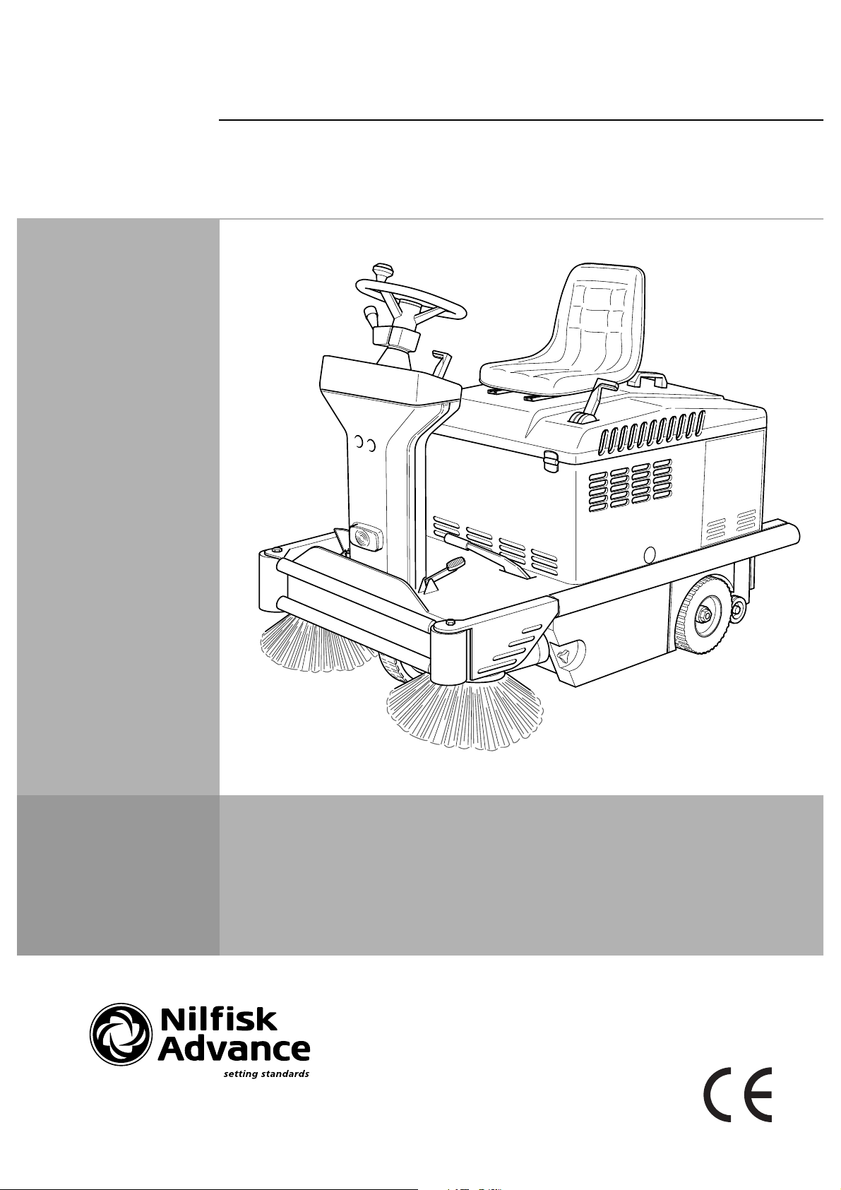
SWEEPER
SR 1100 P/B SR 1200 P/B
SR 5110 P/B SR 5120 P/B
Manual for use and maintenance
FORM No. S31NUK5120(3)2001-04
Page 2
INDEX
Model:
Serial No.:
Power:
Tot weight:
Tot weight:
(w/o battery)
Type G&E Floor cleaning machine.
MADE IN ITALY
Prod. No.:
Max axel rear:
Max axel front:
Noise level:
Voltage:
Nilfisk-Advance Italia
Località Novella terza
26862 Guardamiglio (Italia)
S31NUK5120(3)2001-04
INTRODUCTION / GENERAL INFORMATION ............................................................................. 1
UNPACKING .................................................................................................................................. 2
TECHNICAL DATA ........................................................................................................................ 3
DESCRIPTION OF COMMANDS AND CONTROL PANEL.......................................................... 4
PRELIMINARY OPERATIONS ...................................................................................................... 5-7
USE ................................................................................................................................................ 8-13
USE OF THE WORKING PROGRAMS .................................................................................... 9
FURTHER PERFORMANCES OF THE MACHINE
WITH PETROL ENGINE ........................................................................................................... 13
SIDE BRUSHES ADJUSTMENT AND REPLACEMENT .............................................................. 14
MAIN BRUSH REPLACEMENT .................................................................................................... 15-16
FILTER CLEANING AND REPLACEMENT .................................................................................. 17-18
MAINTENANCE ............................................................................................................................. 19-22
BATTERIES: CONTROL AND RECHARGE............................................................................ 19
BRAKES ADJUSTMENT.......................................................................................................... 20
FRONT LAMP REPLACEMENT............................................................................................... 20
MAINTENACE OF THE PETROL ENGINE .............................................................................. 21-22
SUMMARY OF MAINTENANCE CONTROLS (battery version) ............................................ 23
SUMMARY OF MAINTENANCE CONTROLS (petrol version) .............................................. 24
OPTIONAL ITEMS ......................................................................................................................... 25
SAFETY FUNCTIONS AND TROUBLE-SHOOTING .................................................................... 26
SERVICE ADDRESSES................................................................................................................. 27
Page 3

INTRODUCTION / GENERAL INFORMATION
This manual will help you get the most from your Nilfisk SR1100 - SR1200. Read it thoroughly before operating the
machine. Specifications and details are subject to change without prior notice.
SPARE PARTS AND MAINTENANCE
Repairs, when required, should be performed by Nilfisk-Advance service personnel using Nilfisk-Advance original
replacement parts and accessories. Any “left,, or “right,, indication are always defined with reference to the machine
forward movement direction.
When calling Nilfisk-Advance for repair parts or service, please specify the Model and the Serial Number when
discussing your machine.
CHANGES AND IMPROVEMENTS
Our company constantly improves its products and reserves the right to make changes and improvements at its
discretion without being obliged to apply such benefits to the machine that were previously sold.
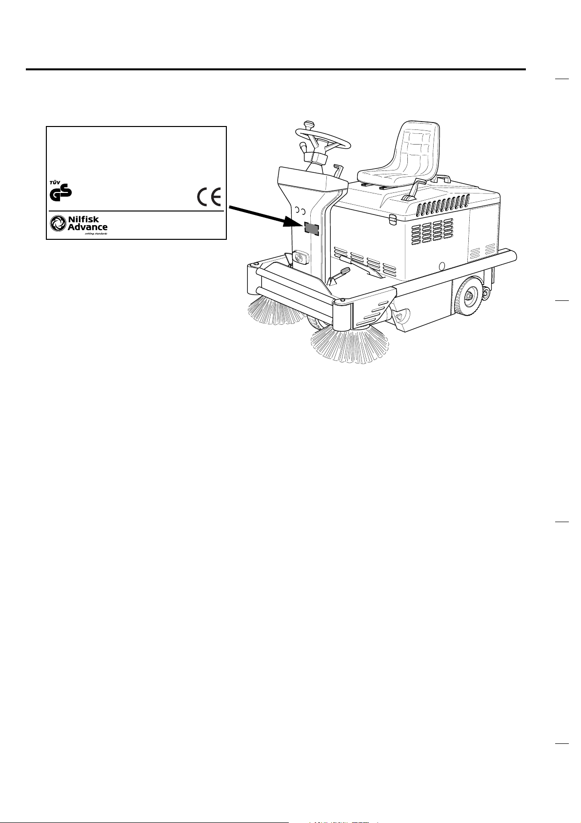
NAME PLATE
The Model and the Serial Number of your machine are shown on the Name plate located on the steering column.
This information is needed when ordering repair parts for the machines. Use the space below to note the Model and
the Serial Number of your machine for future reference.
MODEL_________________________________________
SERIAL NUMBER_________________________________
S31NUK5120(3)2001-04
GENERAL SAFETY RULES
Carefully follow the rules described below to avoid injury to the operator and damage to the machine.
Carefully read the labels on the machine, do not cover them for any reason and replace them immediately if they
become worn or damaged.
- The machine storage temperature range should be between 32˚F and 104˚F
- The machine working temperature is from +32°F to +104°F
- Humidity range should be between 30% and 95%.
- Do not use the machine in an explosive atmosphere environment
- Do not use the machine as a transport vehicle.
- Do not allow the brushes to operate while the machine is stationary to avoid damaging the floor.
- In case of fire, use a powder extinguisher.
- Do not bump into shelves or scaffolding where there is a risk of falling objects.
- Adjust the operating speed to the floor conditions.
- Do not exceed the declared slope limit to avoid an unstable condition.
- When the machine is parked, remove the key and engage the parking brake.
- When machine-operating malfunction occur, make sure that they are not caused by a lack of routine maintenance.
If not, request assistance from the service centre.
- If parts must be replaced, request ORIGINAL spare parts from a dealer or Authorised Retailer.
- Before any maintenance operations, disconnect the electric power supply from the batteries.
- Do not remove guards which require the use of tools to be disassembled.
- Do not wash the machine with pressurised water, or with corrosive substances.
- A service centre should inspect the machine every 200 hours of operation.
- The machine must be disposed of properly, because of the presence of toxic-harmful materials (battery acid, oil,
etc.) which are subject to standards that require disposal in special centres.
- The machine will not generate damaging vibration.
SAFETY- ACCIDENT PREVENTION
No accident prevention program is effective without the complete co-operation of the person directly responsible for
operating the machine. Most of the accidents that may occur in a company, on the job or during transfers are caused
by not-observing fundamental safety rules. A careful and cautious user is the best guarantee against accidents and
is more effective than any type of prevention program. While using the machine pay attention to your surroundings
and people nearby, especially to children.
SAVE THESE INSTRUCTIONS !!
1
Page 4
1
2
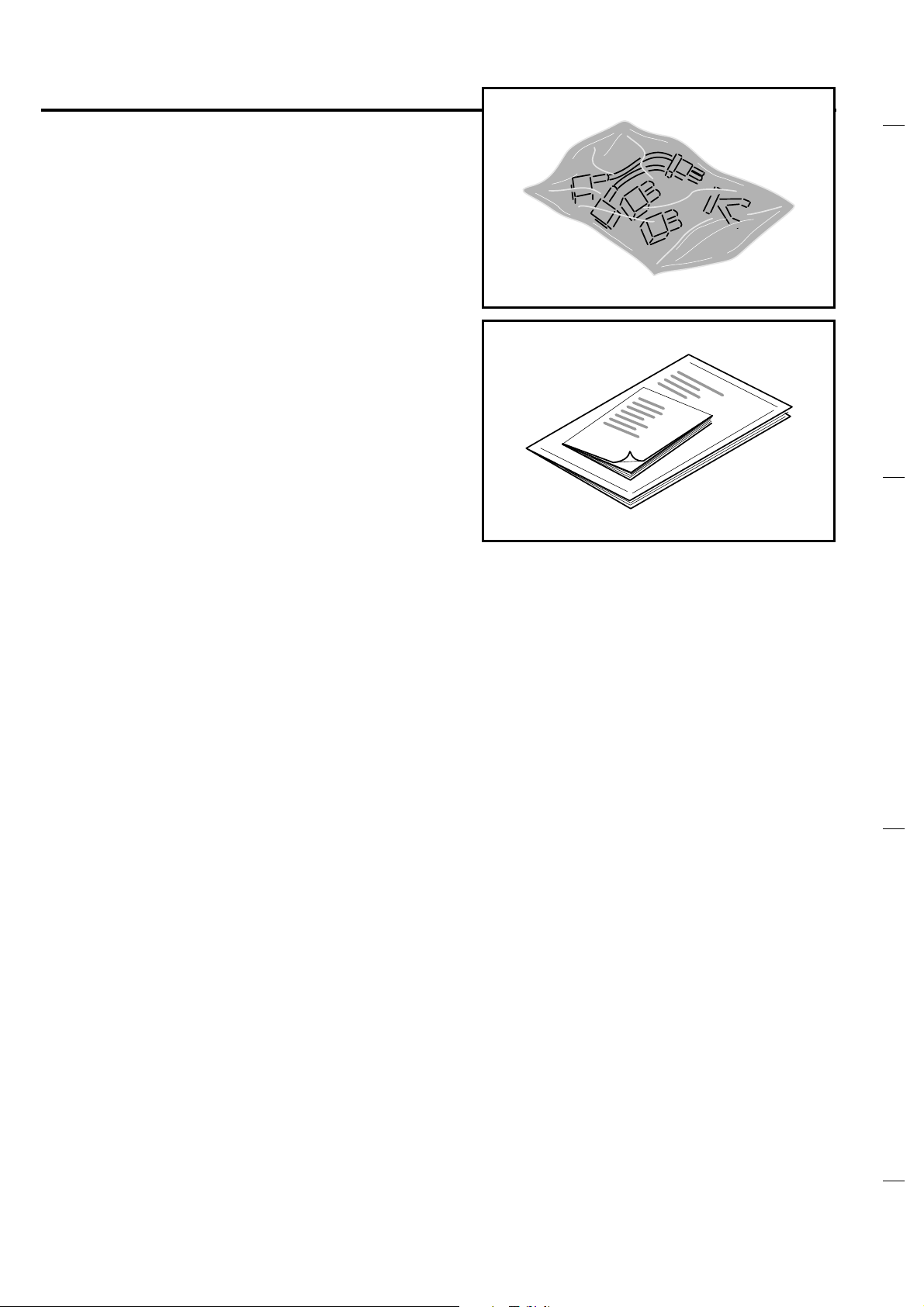
UNPACKING
Please check that the following items are
supplied with the machine:
- envelope with cables for batteries and
connector for battery-charger.
- technical documents (Spare Parts Catalogue,
Manual for Use and Maintenance and - for the
petrol version only - Use and Maintenance
Manual of the engine).
S31NUK5120(3)2001-04
2
Page 5

TECHNICAL DATA
S31NUK5120(3)2001-04
VERSION SR 1100B - SR 5110B SR 1100P - SR 5110P SR 1200B - SR 5120B SR 1200P - SR 5120P
Voltage 24V 24V 24V 24V
Engine model / Honda G150 -K1 144 cc / Honda G150 -K1 144 cc
Nominal Power at 3600
RPM
Power at 3200 RPM
setting
Start / Electric / Electric
Drive electric motor 450W - 120 RPM 450W - 120 RPM 550W - 330 RPM 550W - 330 RPM
Main brush electrical
motor
Suction electric motor 200W - 3300 RPM 200W - 3300 RPM 200W - 3300 RPM 200W - 3300 RPM
Side brush electric motor 60W - 120 RPM 60W - 120 RPM 90W - 120 RPM 90W - 120 RPM
Forward speed max 7 km/h max 7 km/h max 9 km/h max 9 km/h
Reverse speed max 3,5 km/h max 3,5 km/h max 4 km/h max 4 km/h
Max slope 20% 20% 20% 20%
Main brush Ø 300 mm x 700 mm Ø 300 mm x 700 mm Ø 300 mm x 800 mm Ø 300 mm x 800 mm
Side brush Ø 430 mm Ø 430 mm Ø 460 mm Ø 460 mm
Cleaning width with 1
side brush
Cleaning width with 2
side brushes
Front wheel (NR 1) Ø 250 mm Ø 250 mm Ø 250 mm Ø 250 mm
Rear drive wheels (NR 2) Ø 250 mm Ø 250 mm Ø 250 mm Ø 250 mm
Container capacity 70 lt 70 lt 100 lt 100 lt
Panel filte r 2,95 m
Electric filter shaker 90W - 6000 RPM 90W - 6000 RPM 90W - 6000 RPM 90W - 6000 RPM
Machine length 1376 mm 1376 mm 1489 mm 1489 mm
Width 910 mm 910 mm 1020 mm 1020 mm
Height 1193 mm 1193 mm 1251 mm 1251 mm
Weight (without batteries) 240 kg 280 kg 300 kg 350 kg
Fuel tank capacity / 2,5 lt / 2,5 lt
Engine oil tank capacity / 0,7 lt / 0,7 lt
500W - 1600 RPM 500W - 1600 RPM 500W - 1600 RPM 500W - 1600 RPM
/ 3,8 Hp - 2,8 Kw / 3,8 Hp - 2,8 Kw
/3 Hp - 2,2 Kw / 3 Hp - 2,2 Kw
900 mm 900 mm 1050 mm 1050 mm
1100 mm 1100 mm 1250 mm 1250 mm
2
2,95 m
2
2,95 m
2
2,95 m
2
3
Page 6
19
1
2
3
4
5
6
7
8
9
4 10
11
12
13
14
15
16
17
18
19
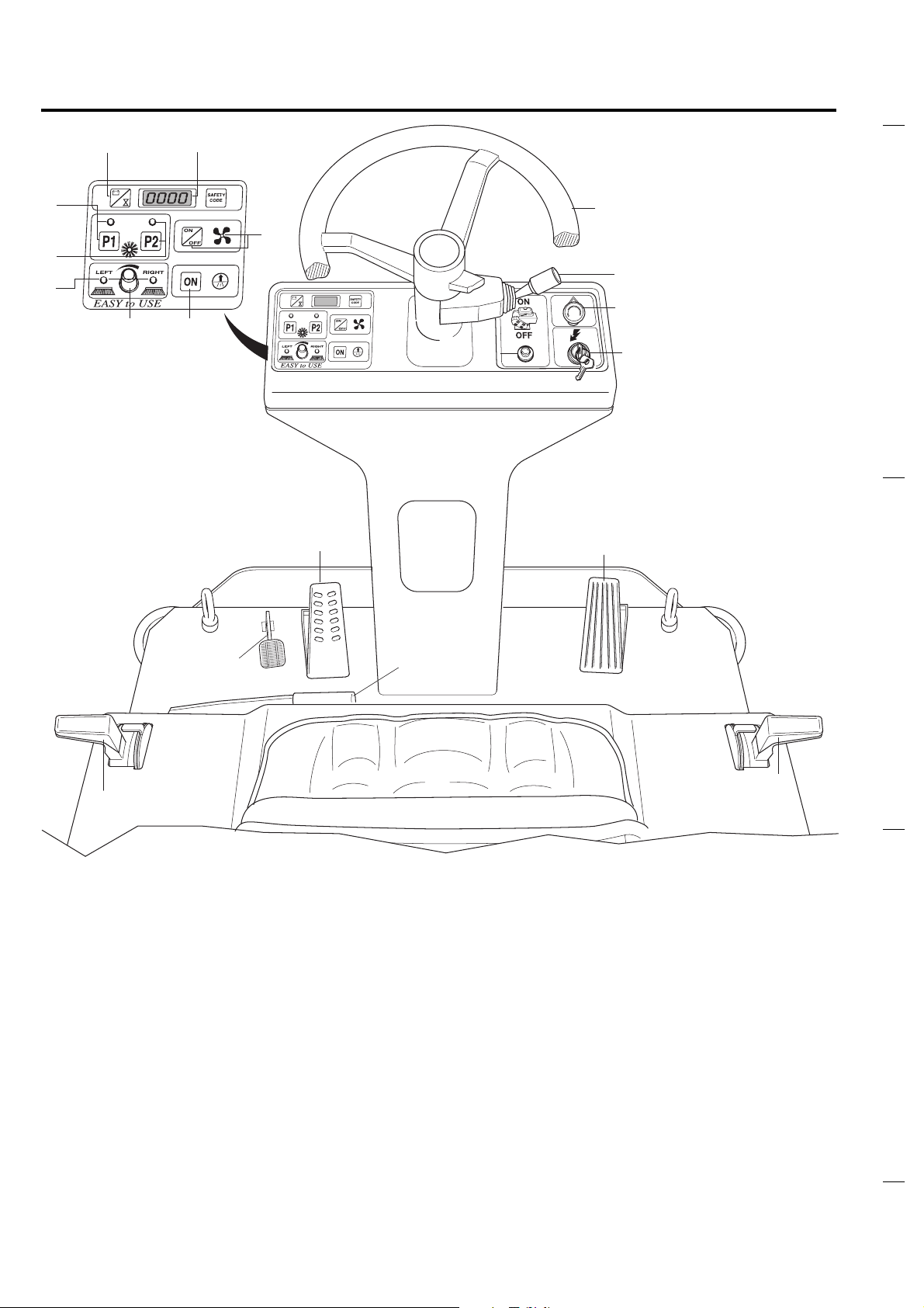
DESCRIPTION OF COMMANDS AND
CONTROL PANEL
1
2
3
5
4
7
6
8
11
S31NUK5120(3)2001-04
13
12
9
10
15
14
18
- Voltmeter/hourmeter push button
- Display
- Button for selection/indicator of working
program P1
- Button for selection/indicator of working
program P2
- ON/OFF button and indicator of suction
motor
- Knob for the speed adjustment of the
side brushes
- Indicator of the operation of left/right side
brushes
- ON button of filter-shaker motor
- Emergency stop push button
16
17
19
- ON/OFF main key switch
- Start/Stop push button for petrol engine
- Selection of forw./reverse speed, light ON/
OFF, horn
- Steering wheel
- Pedal for flap lifting
- Brake pedal
- Accelerator
- Parking brake lever
- Lever for left side brush command
- Lever for right side brush command
Page 7
1
2
3
1
1a
1b
PRELIMINARY OPERATIONS
Both versions of the machine, petrol and battery,
require a 24 V battery set.
Depending on the country where the machine is
sold three possibilities can occur:
- the battery is supplied with the machine and it
is set, complete with acid solution
- the battery is supplied with the machine and it
is set, but not complete with acid solution
- the battery is not supplied.
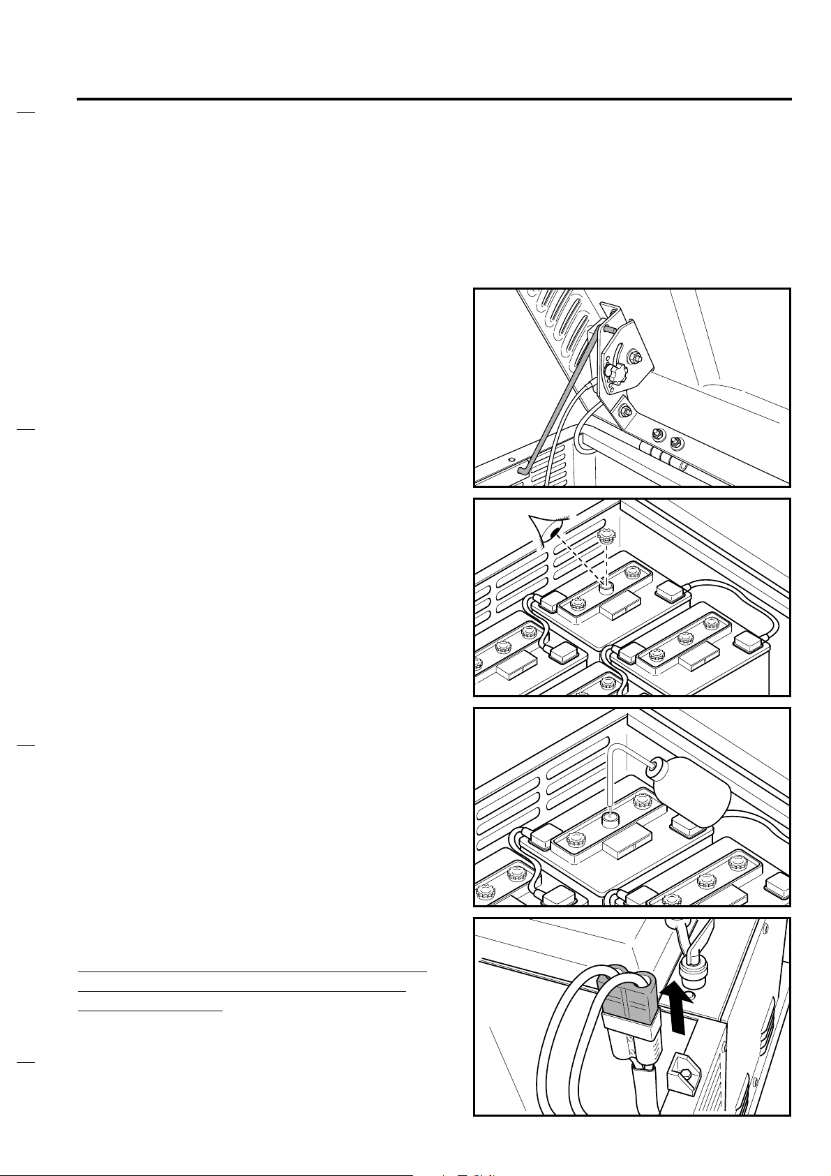
The battery compartment is under the seat: lift
the compartment lid, towards the steering wheel,
and verify which one of the three possibilities is
applied to your machine.
S31NUK5120(3)2001-04
If the batteries are installed open one of the caps
of every battery and check if they are filled with
electrolyte.
- If the battery is filled:
. Check the electrolyte level in every cell and -
if necessary- fill up with distilled water.
. Proceed with a battery recharge according to
the MAINTENANCE paragraph and to the
Battery User Manual.
WARNING: before starting the recharge the
battery connector must be disconnected
from the machine.
After the recharge plug the battery connector to
the machine.
5
Page 8
2
PRELIMINARY OPERATIONS
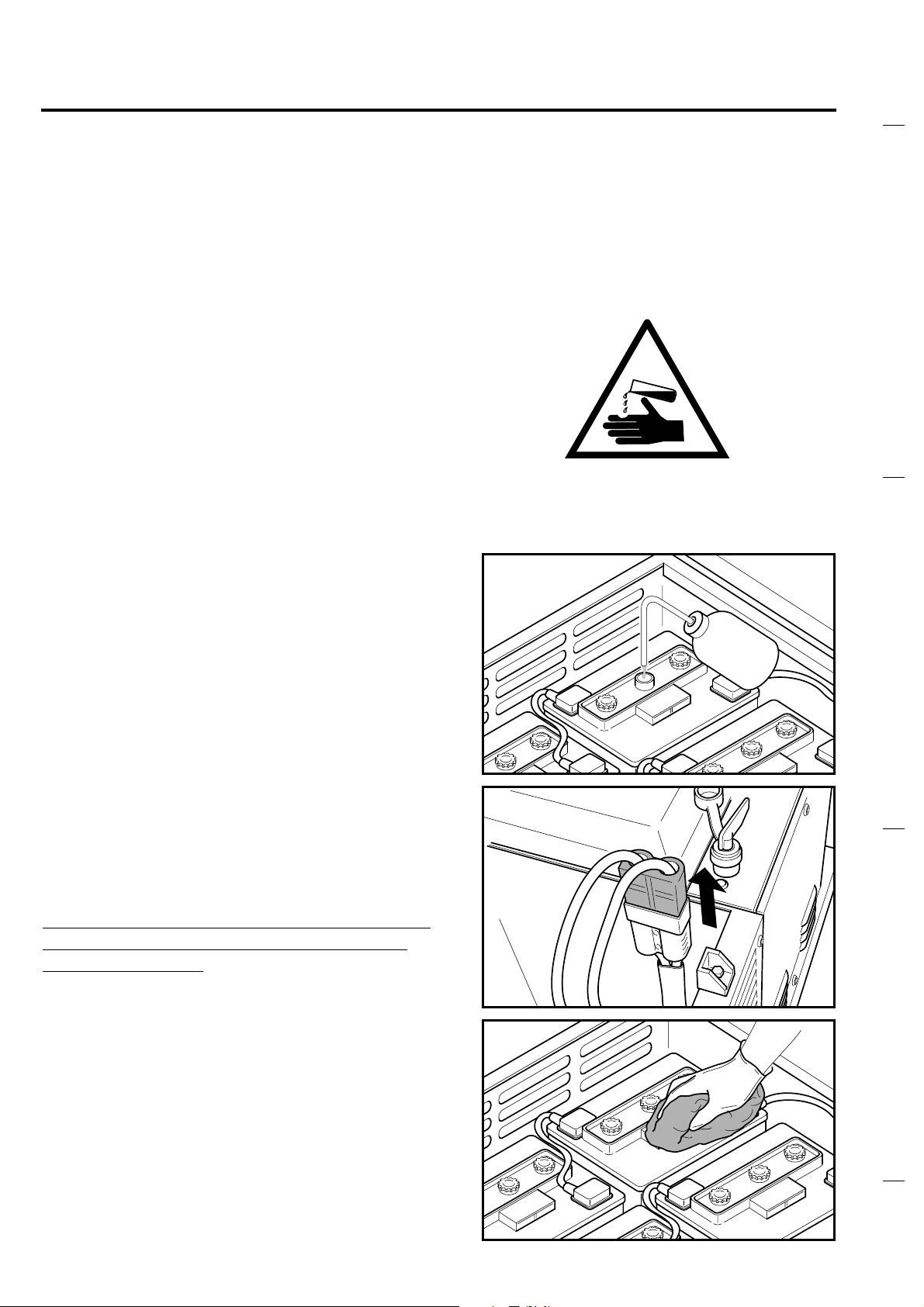
- If the batteries are installed but not filled with
acid solution they must be filled with a solution
of sulphuric acid (density between 1,270 Kg
and 1,290 Kg at 25°C temperature) according
to the instructions specified below and in the
Battery User Manual.
BATTERY FILLING UP WITH ACID SOLUTION
Warning: the battery acid is corrosive; if it
comes in contact with the skin or eyes rinse
thoroughly with water and consult a
physician.
The batteries must be filled in a well
ventilated area.
S31NUK5120(3)2001-04
Fill every battery cell with acid; the right level is
specified in the Battery User Manual.
After one hour fill up with acid, if necessary.
Let batteries rest for a further hour; then proceed
with a recharge according to the instructions
specified in the Battery User Manual and in the
MAINTENANCE paragraph. During the recharge
the battery caps must be open.
WARNING: before starting the recharge the
battery connector must be disconnected
from the machine.
After the recharge close all the cell caps and
clean the top of the battery from any acid
remains.
6
Page 9
3
PRELIMINARY OPERATIONS
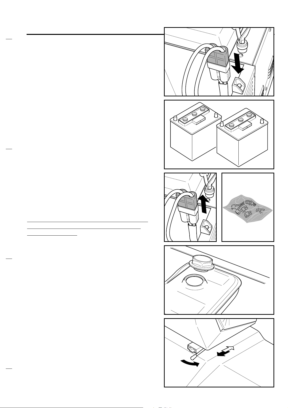
Connect the battery connector to the machine.
- If the machine is not equipped with batteries
they must be procured and mounted. It is
recommended to get the assistance of
qualified personnel to choose and set the
batteries.
S31NUK5120(3)2001-04
The electric cables supplied with the machine
can be used for the connection of the four
batteries.
WARNING: before starting the recharge the
battery connector must be disconnected
from the machine.
Fill the fuel tank with UNLEADED PETROL and
close the engine compartment.
Check the engine oil level according to what
specified in chapter “Maintenance”
After having set the batteries, climb onto the
machine and adjust the seat to find the most
comfortable position.
Now the machine is ready to be used.
7
Page 10

)
)
USE
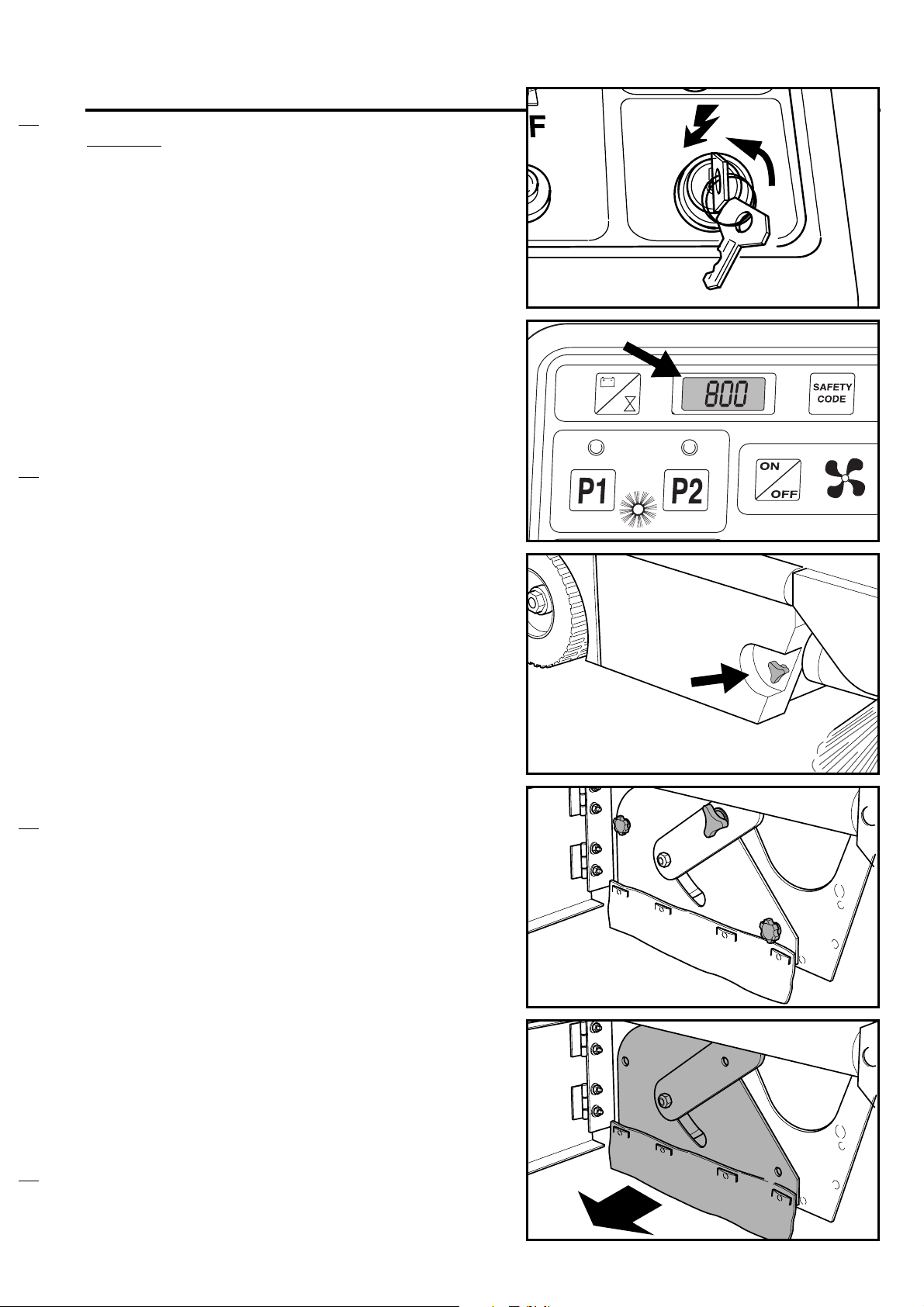
Insert the ignition key into the panel and turn it
clockwise: the display will show all zeros and after
about three seconds the battery voltage will appear.
Note : the temporary lighting of the two side brush
indicators and the short sound from the reverse
speed acoustic indicator are to be considered a
normal behaviour.
Wait not less than three seconds before restarting the
machine after switching Off.
Check the charge status of the batteries on the
display.
Six different data/functions can be shown on the
display.
The six functions are described in the following table
Displayed datum/function
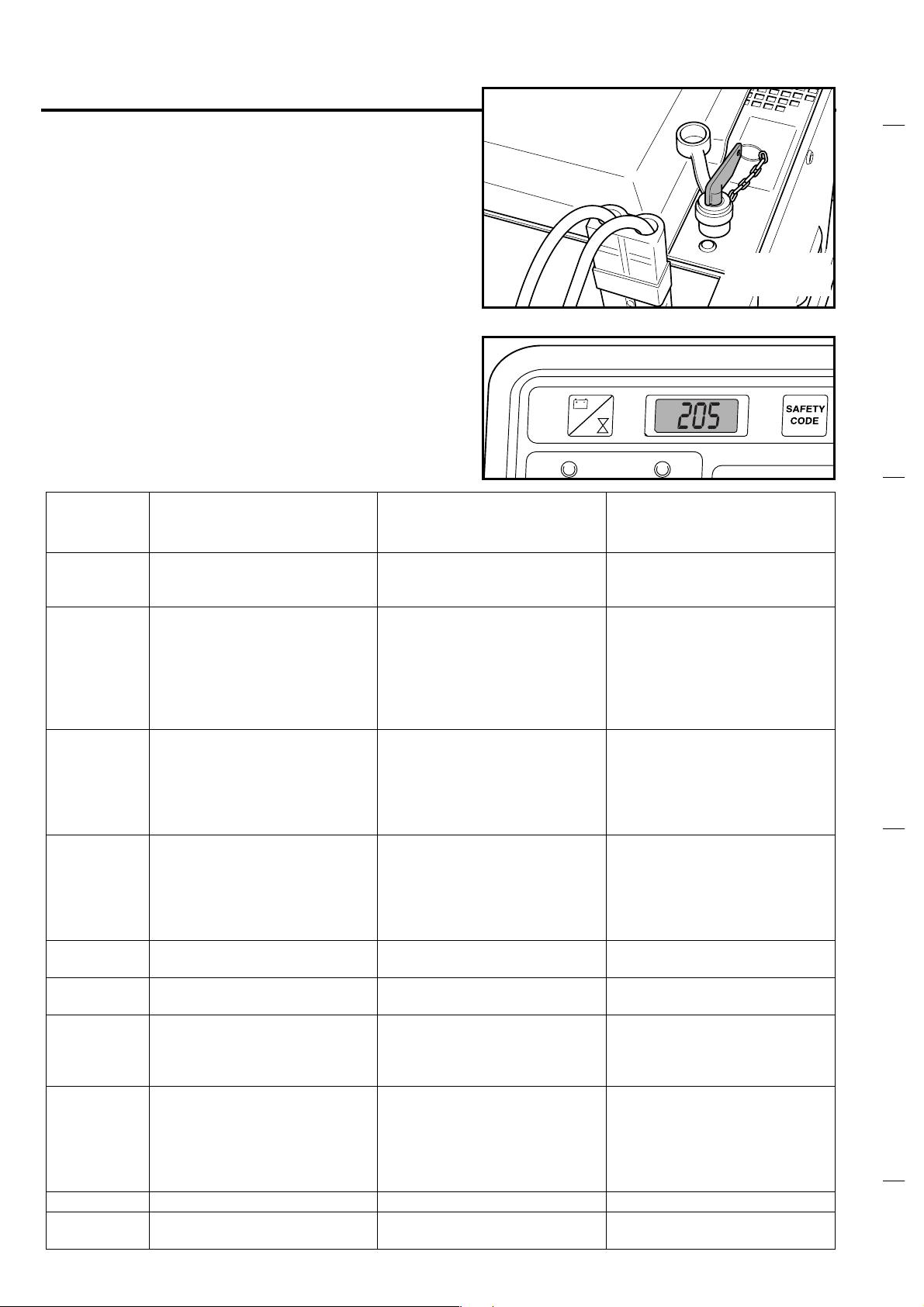
1. Voltmeter : the battery voltage is normally shown on the
display. A block function will be activated in case of battery
undervoltage: when battery voltage will be about 20V all
machine functions will stop, except traction; in this case the
display will show 0205; proceed then with a battery recharge
(see Maintenance paragraph)
2. & 3. Hourmeter : to read the machine working time - in
hours - press once the yellow display button. By pressing the
button a second time the working minutes will appear. Just
waiting ten seconds the display will show the battery voltage
again
4. Total swept surface (m
each 1000 m
5. Daily swept surface (m
each 10 m
6. Productivity : sweeping rate m
instantaneous machine working speed
2
2
2
: the displayed value will increase
2
: the displayed value will increase
2
/hour: it depends on the
Display
reading
Normally fixed.
(battery voltage)
Flashing when
0205 appears.
Fixed
Fixed
Fixed
Flashing
S31NUK5120(3)2001-04
.
Notes :
- to pass to the next function press the yellow display
button once, 10 seconds after choosing one of the
possible data/functions
- the display will return automatically to the battery
voltage from every function
- data 2 and 3 will increase just using the traction
function (accelerator pedal)
- data 4, 5 and 6 will increase only if main broom is
turning AND traction function is used
- when datum 5 is displayed you can reset it just by
keeping the yellow display button pressed 5
seconds.
- If the batteries are charged enough, now it is
possible to start the job (in battery mode).
If the machine is equipped with the gasoline engine,
proceed with the start of the engine itself.
START/STOP OF THE PETROL ENGINE
To start the gasoline engine press the red button
shown in the figure; to stop the engine press the
same button again.
8
Page 11

P1
P2
USE
USE OF THE WORKING PROGRAMS
Once the machine has been turned on and
eventually after starting the petrol engine,
choose one of the two working programs P1 and
P2 according to your cleaning need and press
the relevant button:
is the “light cleaning program” (for internal
environment, i.e. smooth floor, moquette, small
debris etc.)
is the “hard cleaning program” (for external
environment, i.e. asphalt, uneven floor, big
debris etc.).
P1
S31NUK5120(3)2001-04
P2
After having pressed the preferred button the
relevant light indicator will turn on, together with
the suction motor indicator.
The temporary activation of the main brush and
suction electric motors will also occur; (the
relevant light indicators will flash).
Note : the working parameters of programs P1
and P2 are pre-set by the manufacturer of
the machine: if you want to change the
pre-set values call the customer service
personnel of your supplier.
Lower the side brush/es by pressing the top of
the relevant lever and moving it forward.
Note : on the control panel the corresponding
light indicators will turn on.
To lift the side brush/es press the top of the
levers and move them backwards.
Note : the side brush/es, the main brush and the
suction fan will start automatically when
the accelerator pedal will be pressed
(AUTO POWER-ON).
9
Page 12

USE
It is possible to adjust the side brush/es turning
speed by means of the dedicated knob.
Select the forward speed by means of the
command lever.
Press the accelerator pedal to start the job.
S31NUK5120(3)2001-04
Note : by releasing the accelerator pedal (or
setting the command lever to the neutral
position) the automatic switch off of all
functions will occur within 8 seconds (Auto
Power Off); the light indicators of the
selected working program and of the
suction fan will start flashing. The
automatic restart of all functions will
automatically occur as soon as the
accelerator pedal will be pushed again
(Auto Power ON).
In order to enable the selection of a
different working program first disable the
previously selected one.
When it is necessary to sweep on a wet floor
stop the suction fan pressing the relevant button,
in order to prevent the damage of the paper
panel filter.
In order to get an efficient cleaning function the
panel filter must always be clean.
Press the filter-shaker button, even if the
machine is working.
This operation must be repeated every 10 to 15
minutes, depending on the kind of rubbish to be
swept; before emptying the dirt container and, in
any case, at the end of the work.
10
Page 13

USE
To collect light and bulky debris lift the front flap
using the left pedal (do not press the pedal down
for a long time, not to reduce the suction
capability of the machine).
The machine gets an automatic breaking
function when the accelerator pedal is released;
when necessary the service brake can also be
used (see the figure).
S31NUK5120(3)2001-04
When driving in reverse gear an intermittent
acoustic signal will be heard and all the functions
will remain active.
The figure shows the functions of the command
lever:
1- forward gear
2- reverse gear
3- horn
4- front light On/Off.
The machine is equipped with an emergency
stop button; by pressing this button (red light On)
a sudden stop of the machine will occur and all
functions will turn off, the petrol engine too.
To restart the machine turn the red button
clockwise (according to the arrow shown on the
button itself).
4
1
3
2
To restart the normal operation re-select one of
the two working programs P1 or P2.
A safety device is located inside the operator
seat: the drive function - either forward or
reverse - is disabled as soon as the operator will
stand up or leave the seat.
11
Page 14
USE
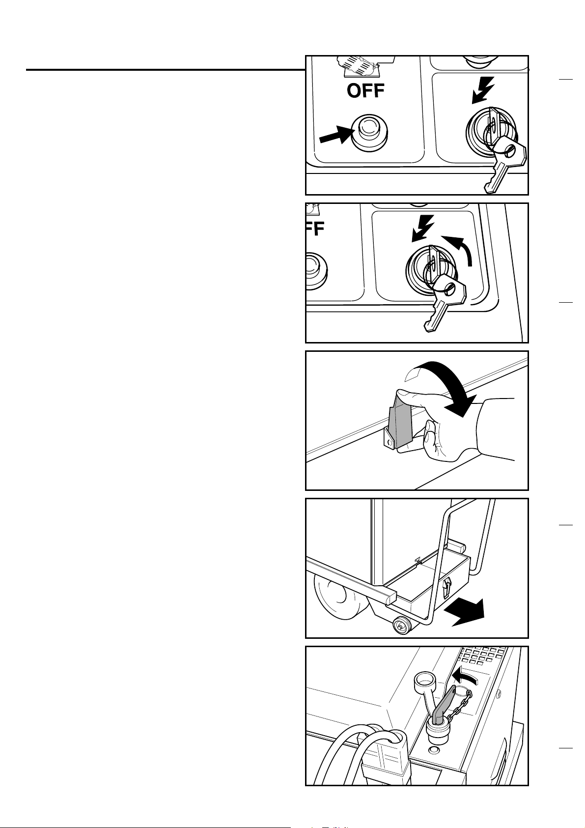
At the end of the job turn off the selected working
program (P1 or P2) and switch the petrol engine
off by pressing the button shown in the figure.
Before leaving the machine make sure that the
side brushes are lifted, the parking brake
engaged and the master key in the OFF position.
(counter clockwise)
S31NUK5120(3)2001-04
At the end of the job or whenever it is necessary
empty the rear dirt container.
In the event that the machine must be pushed
when switched Off turn the proper red key
counter-clockwise (see the figure), in order to
disengage the electric drive motor and disable
the self-breaking function. Turn and eventually
remove the red key that can be seen after lifting
the lid of the battery compartment.
12
Page 15

USE
FURTHER PERFORMANCES OF THE
MACHINE WITH PETROL ENGINE
The machine equipped with the petrol engine is
able to work with full performance even if the
petrol engine is turned Off; this could occur just
because the machine run out of the fuel or when
it is necessary to work in a closed environment.
In this case the available working time will
depend on the capacity (amper.hours) of the
batteries installed on the machine; on the
intensity of the selected working program; on the
charge status of the batteries.
On this machine, in order to guarantee the
reliability of the batteries, two safety features are
envisaged:
S31NUK5120(3)2001-04
1- protection against the deep discharge of the
battery: when the battery voltage drops down to
about 20 Volt the automatic stop of all function
will occur - except the traction function. When it
is in this condition, it is necessary to proceed with
the recharge of the battery or to start the petrol
engine.
2- Protection against the excessive recharge. If
the battery voltage will be over 29 Volt the
automatic stop of the petrol engine will occur.; in
any case the machine will still be able to operate
only with batteries. The petrol engine can be
restarted when the battery voltage will be low
enough (at about 24 Volt).
13
Page 16

SIDE BRUSHES ADJUSTMENT AND
REPLACEMENT
Warning: the following operations must be done
with the machine in Off condition and master key
out, on a flat floor.
When the side brush is worn its height must be
adjusted.
Loosen the knob. Turn the adjusting disk and
move its position of one hole.
And tighten the knob.
S31NUK5120(3)2001-04
To check the adjustment of the brush start it and
verify that the contact with the floor is as shown
in the figure. If necessary repeat the adjustment
sequence.
When the brush is remarkably worn out, it is
necessary to replace it. Just press the two tabs
inwards and remove the brush. Reinstall the new
brush by carrying out the reverse operation;
apply a light pressure to the brush with your
hands.
Note: when the brush is replaced set the
adjusting devices to their original position
(corresponding to brush new, with no
wear).
14
Page 17
MAIN BRUSH REPLACEMENT
Warning: the following operations must be done
with the machine in Off condition and master key
out.
This machine is equipped with an automatic
control of the main brush pressure; this also
means that the position of the main brush is
automatically adjusted (no need of manual
adjustment).
The complete wear out of the main brush - and
therefore the need to replace it - is notified with
code 800 on the display.
S31NUK5120(3)2001-04
Please meet the following procedure for the main
brush replacement.
Open the side door on the right side of the
machine, unscrewing the knob shown in the
figure.
Remove the three knobs used to fix the lid of the
main brush compartment.
Remove the lid.
15
Page 18

MAIN BRUSH REPLACEMENT
Remove the worn out brush.
Fit the new brush in its compartment, paying
attention to the engagement of the plastic
adapter with the hub on the opposite side of the
compartment.
S31NUK5120(3)2001-04
Fit the lid of the main brush compartment using
the three knobs previously removed.
16
Page 19

FILTER CLEANING AND REPLACEMENT
The panel filter requires a regular cleaning.
Lift the lid.
Remove the lid of the filter compartment.
S31NUK5120(3)2001-04
Disconnect the electric cable of the filter-shaker
motor (the machine must first be switched off
and the key out).
Loosen the two screws with butterfly head on the
two sides of the metal frame fixing the panel
filter; it is not necessary to remove the screws
completely.
Remove the metal frame and take the panel filter
out.
Clean the filter shaking, blowing it with
compressed air - pressure not higher than 6 barfrom the side where the metal protection net is
mounted, to avoid damaging to the paper.
17
Page 20

FILTER CLEANING AND REPLACEMENT
After cleaning, fit the filter and the relevant fixing
frame.
Tighten the two screws with butterfly head and
reconnect the filter shaker electric cable.
If the filter is damaged or can not be properly
cleaned replace it with a new one.
Ask to your supplier for the new spare parts list.
Polyester panel filters are also available.
S31NUK5120(3)2001-04
18
Page 21

MAINTENANCE
BATTERIES: CONTROL AND RECHARGE
Make a frequent check of the electrolyte level
inside every battery cell. The battery
compartment is under the operator seat; lift the
lid and open the caps of all the battery cells:
when necessary fill up the cells with distilled
water.
The proper electrolyte level is specified in the
Manual for use and maintenance of the battery.
S31NUK5120(3)2001-04
Warning
battery level check must be done every week.
After filling close all the cell caps and clean the
top of the battery from any acid remains.
Warning: the battery acid is corrosive; if it comes
in contact with the skin or eyes rinse thoroughly
with water and consult a physician.
When necessary proceed with a recharge of the
battery according to the following instructions
and taking also into account what is specified in
the Battery User Manual:
- switch the machine Off and remove the master
key.
Warning: before starting the recharge the
battery connector must be disconnected
from the machine.
: On the version with petrol engine the
- the recharge must be done in a well ventilated
area
- open all the cell caps
- connect the battery connector to the battery
charger connector
- connect the battery charger cable to the mains
(please check that the voltage and frequency of
the mains correspond to the data of the
charger)
At the end of the recharge disconnect the battery
from the charger and fit the battery connector to
the machine. Close all the cell caps and clean
the top of the battery from any acid remains.
Note: in any case refer to the instructions
specified in the Battery Use Manual.
19
Page 22

MAINTENANCE
BRAKES ADJUSTMENT
When the pedal brake and/or the parking brake
reach a low efficiency operation some
adjustments can be done on the front wheel
(models SR 1100 e SR 5110):
- loosen the locking nut A
- turn adjuster B
- tighten locking nut A.
On models SR 1200 and SR 5120 the two
brakes on the rear wheels can also be adjusted,
by means of the regulating devices located
under the foot board (under the brake pedal).
S31NUK5120(3)2001-04
B
A
FRONT LAMP REPLACEMENT
In order to replace the front lamp:
- remove the transparent cover
- push the lamp and turn it counter-clockwise to
remove it
- replace the lamp paying attention to the volt
and watt ratings
- fit the transparent cover.
20
Page 23
MAINTENANCE OF THE PETROL ENGINE
(HONDA)
MAINTENANCE OF THE PETROL ENGINE
(HONDA)
First: read thoroughly the Use and Maintenance
Manual of the engine.
Here below some recommendations are pointed
out.
Check the engine oil level at each working
session; for possible fill up read the oil type
specified on the engine Manual
Warning: the engine oil must be replaced the
first time after 20 working hours or, in
any case, not later that one month
since the receipt of the machine.
Afterwards it must be replaced every
100 hours or not later than 8 months
since the last replacement.
S31NUK5120(3)2001-04
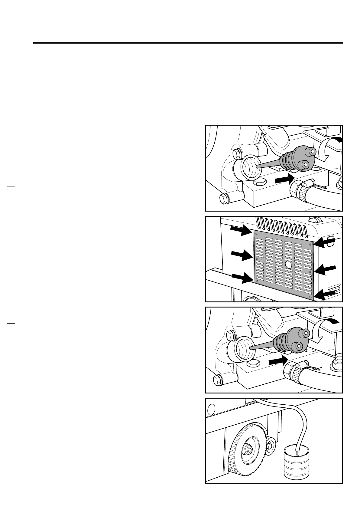
The procedure for the replacement of the engine
oil is specified here below.
Remove the side panel from the machine.
Unhook the engine oil emptying hose.
Slip off the engine oil level check rod.
21
Page 24

MAINTENANCE
Remove the cap from the engine oil emptying
hose and let the oil come out.
Note: it is suggested to remove the oil when the
engine is warm.
Dispose of the used oil in proper special
containers.
S31NUK5120(3)2001-04
Note: keep the emptying hose lifted and open
during filling.
Take a funnel and pour in the new oil (type
indicated in the engine Use e Maintenance
booklet) from the hose of the rod for oil level
check. Fit the rod for oil level check and close the
emptying hose with its cap.
At the end of the filling sequence check the
engine oil level.
Make a periodic check of the engine air filter.
If necessary wash the engine air pre- filter (A)
with water and soap or any other detergent for
domestic use.
Squeeze it and dry it well.
B
A
Proceed by cleaning the filter B with compressed
air (pressure not higher than 6 bar).
If the filter can’t be completely cleaned, replace
it.
Fit the engine air filter in its compartment and the
relevant cover.
22
Page 25

SUMMARY OF MAINTENANCE
CONTROLS (battery version)
Warning: the following interventions must be
done with machine in Off condition and master
key out. All the periodic maintenance operations
must be performed by skilled personnel or by an
authorized service centre.
Note: the battery life will depend on a good
periodic maintenance (check of the level of the
electrolyte and of battery voltage). Besides it
must be taken into account that an unused
battery is submitted to a self-discharge
phenomenon. In the event that the machine is
not used for a long time (e.g. 3 or 4 weeks) it is
necessary TO RECHARGE THE BATTERY; in
fact the battery voltage MUST NEVER drop
down below 20 Volt.
S31NUK5120(3)2001-04
CONTROL
Battery liquid level and
voltage
check
UPON
DELIVERY
●
EVERY
30
HOURS
●
OR EVERY TWO
WEEKS
EVERY
50
HOURS
EVERY 100
HOURS
EVERY 400
HOURS
Check the carbon brushes
of all electrical motors and
●
replace them if worn
Belt tension ●●
Brake adjustment ●●
Filter shaker ●
Nut and screw tightness ●
Wear of main brush and
●
side brushes
Panel filter cleaning ●
Sealing of gaskets of filter
●●
compartment and of flaps
Clean the steering chain
and (SR 1200 - SR 5120
only) the traction wheels
chains with gas-oil or a
proper solvent.
23
●
Page 26

SUMMARY OF MAINTENANCE
S31NUK5120(3)2001-04
CONTROLS (petrol version)
Warning: the following interventions must be done with machine in Off condition and master key
out. All the periodic maintenance operations must be performed by skilled personnel or
by an authorized service centre.
Every maintenance intervention on the petrol engine must be performed in agreement with the
engine User Manual.
Note: the battery life will depend on a good periodic maintenance (check of the level of the
electrolyte and of battery voltage). Besides it must be taken into account that an unused
battery is submitted to a self-discharge phenomenon. In the event that the machine is not
used for a long time (e.g. 3 or 4 weeks) it is necessary TO RECHARGE THE BATTERY;
infact the battery voltage MUST NEVER drop down below 20 Volt.
CONTROL
Battery liquid level and voltage
check
Engine air filter cleaning ●
Panel filter cleaning ●
Engine oil level check 1st TIME ●
Engine oil replacement ● (+)
Engine RPM check and
adjustment (*)
Check the carbon brushes of all
electrical motors and replace
them if worn
Belt tension ●●
Brake adjustment ●●
Filter shaker ●
Nut and screw tightness ●
Wear of main brush and side
brushes
Sealing of gaskets of filter
compartment and of flaps
Clean the steering chain and
(SR 1200 - SR 5120 only) the
traction wheels chains with gasoil or a proper solvent.
UPON
DELIVERY
●●
●●
TWO
TIMES PER
WEEK
ONE
TIME PER
WEEK
EVERY
20
HOURS
1st TIME
EVERY
50
HOURS
●
EVERY
100
HOURS
● (++)
●
●
EVERY
400
HOURS
●
For SR1100: 3200 engine shaft RPM with no function working and battery voltage higher than 27
Volt
For SR 1200: 3300 engine shaft RPM with no function working and battery voltage higher than 27
Volt
(+) 20 hours or not more than 1 month
(++) 100 hours or not more than 8 months
24
Page 27

OPTIONAL ITEMS
High capacity batteries both for the petrol version
and for the battery version.
Battery charger
S31NUK5120(3)2001-04
Different types of main bushes and side brushes
Polyester panel filter (it can be washed)
-Mini containers
-Flashing beacon on support
-Rollbar
-Flashing beacon on rollbar
-Front rollers and side bumpers
-Non marking wheels
For further information on all accessories get in
touch with your supplier
25
Page 28
SAFETY FUNCTIONS AND TROUBLESHOOTING
The machine is equipped with many safety
devices and functions which have been
described in the USE paragraphs (both for petrol
and electrical versions). For instance the
automatic stop of all functions to avoid the deep
discharge of the battery has been mentioned;
and also the availability of a special red key for
the disengagement of the self-breaking function
has been notified: this is to be operated when the
machine must be pushed in Off condition.
Besides the intervention of other safety functions
is notified by means of dedicated safety codes
appearing on the display. These safety codes
are described in the following table.
S31NUK5120(3)2001-04
TO PUSH
TO DRIVE
SEE SAFETY CODE 333
SAFETY
CODE
205
301 Stop of all functions and traction Overtemperature of the drive motor
302
305 The machine functions will stop
306 Stop of all functions and traction
307 The machine does not start Wrong start sequence
308 The machine does not start
333 The machine does not start
800 Display flashing Main brush worn -Replace the main brush
E10 Flashing display
MACHINE BEHAVIOUR
Stop of all functions except
traction
The machine does not start or, in
the event it was working, will stop
DESCRIPTION OF THE
MALFUNCTION
The battery is empty
Possible problem with traction
control electronic circuit
High temperature on the electronic
control circuits (95 °C)
High temperature on the electronic
control circuits (105 °C)
Damage of the cable of
potentiometer for traction control
-Off status of the red key for the
disabling of the self braking
function (see the picture on the
top page)
-Possible trouble of motor kables
(short circuit or open circuit)
Main broom is blocked Remove the main broom and clean
POSSIBLE INTERVENTION
Recharge the battery according to
the instructions given in the
Maintenance paragraph
-If the machine run on a long ramp it
could be normal: let the machine
cooling 20 minutes
-Check the efficiency of the front
and rear brakes
-Check the rotation of the rear drive
wheels
-Check carbon brushes of traction
motor
-Check connection cables of
traction motor
-If the above is OK replace the
power electronic board
-If the ambient temperature is high
let the machine cool down 20
minutes
-If the problem will remain call the
technical service to check the
electrical motors
-Make the same checks as per code
305
-Release the accelerator pedal
before turning the key On
-Check the cable connections of the
potentiometer for traction control
- Check the potentiometer for
traction control
-Insert the red key and turn it
clockwise
-Check the motor cables
all dirty parts
26
Page 29

SERVICE ADDRESS
S31NUK5120(3)2001-04
AUSTRALIA
Nilfisk-Advance Pty. Ltd.
ACN 003 762 623
Head office: 17 Leeds Street, Rhodes, N. S. W. 2138
Tel.(02) 9736 1244 - Fax (02) 9736 3910
Customer Responce Centre:
Tel.1 800 011 013
BELGIQUE/BELGIË/LUXEMBOURG
Nilfisk-Advance s.a./n.v.
Doornveld/Sphere Business Park
Industrie Asse 3, nr 11- bus 41
1731 Zellik-Asse
Tel.(02) 467.60.50 Fax (02) 463.44.16
CANADA
Nilfisk-Advance Ltd
396 Watline Avenue
Mississauga, Ontario L4Z 1X
Tel.(905) 712-3260 - Fax (905) 712-3255
DANMARK
Nilfisk-Advance Nordic A/S
Myntevej 3, 8900 Randers
Tel.86 42 84 33 - Fax 86 41 19 55
DEUTSCHLAND
Nilfisk-Advance AG
Siemensstraße 25-27
25462 Rellingen
Tel.(04101) 3990 - Fax ( 04101) 399191
Zentraler Kundenservice / Customer Hotline
Tel.0180 53 56 797
ESPAÑA
Nilfisk-Advance, S.A.
Torre D’Ara
Passeig del Rengle, 5 -PI.10
E-08302 Mataró (Barcelona)
Spain
Tel.: 93 741 2400
Fax: 93 757 8020
nilfisk@nilfisk-advance.es
Teléfono nacional de servicio Comercial: 902 200 201
Teléfono nacional de servicio Técnico: 902 300 301
Delegaciones, Distribuidores y Servicio Técnico a domicilio en todas las regiones
de Espagña.
FINLAND/ SUOMI
Oy Tecalemit AB
Hankasuontie 13, 00390 Helsinki
Tel.(89) 547 701- Fax (89) 547 1779
FRANCE
Nilfisk-Advance S.A
BP 246
91944 Courtaboeuf Cedex
Tel.(01) 69.59.87.00 Télécopie (01) 69.59.87.01
PORTUGAL
Nilfisk-Advance Lda.
Rua Cândido de Figueiredo, 91-i, 1500-133 LISBOA
Tel.01/7784142-Fax0l/7785613
Porto 02/526766 - Fax 02/520739
Açores 096/628092/3 - Fax 096/628129
Madeira 091/228965 - Fax 091/228796
SCHWEIZ / SUISSE
Nilfisk-Advance AG
Ringstrasse 19, 9533 Kirchberg/Wil
Tel.719 23 52 83 - Fax 719 23 84 44
SINGAPORE
Nilfisk-Advance Pte. Ltd.
10, Woodlands Loop
Singapore 738388
Tel.(65) 759 9100 - Fax (65) 759 9133
SVERIGE
Nilfisk-Advance AB
Sjöbjörnsvägen 5, 117 67 Stockholm
Tel.085 55 944 00 - Fax 085 55 944 30
TAIWAN
Nilfisk-Advance Ltd
1 F, No.23, Lane 132, Sec. 2
Ta An Road, Taipei
Tel.700 22 68 - Fax 784 08 43
UNITED KINGDOM
Nilfisk-Advance Limited
Newmarket Road
Bury St. Edmunds
Suffolk IP 33 3SR
Tel.(01284) 763163 - Fax (01284) 750562
USA
Nilfisk-Advance Inc.
14600 21st Avenue North
Plymouth, MN 55447-3408
Tel. +1763 475 2235 - Fax 1763 473 1764
Nilfisk-Advance of America, Inc.
300 Technology Drive
Malvern, PA 19355
Tel.(610) 647 647-6427
ÖSTERREICH
Nilfisk-Advance GmbH
Vorarlberg Allee 46
1230 Wien
Tel.1616 58 30 - Fax 1616 58 30 40
HONG KONG
Nilfisk-Advance Ltd
2001, 20/F HK Worsted Mills
Industrial Building
31-39 Wo Tong Tsui Street
Kwai Chung, N.T.
Tel.2427 59 51- Fax 2487 5828
IRELAND
Nilfisk-Advance Ltd
28 Sandyford Office Park
Dublin 18
Tel. +353 12943838 - Fax +353 12943845
ITALIA
Nilfisk-Advance Italia SPA
Località Novella Terza
26862 Guardamiglio ( LO) I
Tel. + 39 (0377) 451124 – Fax + 39 (0377) 51443
JAPAN
Nilfisk-Advance Inc.
3-4-9 Chigasaki Minami
Tsuzuki-Ku Yokohama 224
Tel.045-942-7741- Fax 045-942-6545
MALAYSIA
Mlfisk-Advance Sdn Bhd
Lot 2, 1st. Floor
Lorong l9/1A
46300 Petaling Jaya
Selangor Darul Ehsan
Tel.03-7568188/03-7568189/03-7568388-Fax03-7566828
NEDERLAND
Nilfisk-Advance B.V.
Flevolaan 7, Postbus 341
1380 AH Weesp
Tel.0294-462121- Fax 0294-430053
NEW ZEALAND
Nilfisk-Advance Limited
477 Great South Road, Penrose
Auckland
Tel.(09) 525 0092 - Fax (09) 525 6440
NORGE
Nilfisk-Advance AS
Enebakkvn, 119, 0680 Oslo, Postboks 196, Manglerud, 0612 Oslo
Tel.22 08 63 50 - Fax 22 08 63 63
Distriktsrepresentanter over hele landet
27
Page 30

Graphic project VISUAL DIVISION Milan Italy
COD.S31NUK5120(3)2001-04
Nilfisk-Advance Italia S.p.A
Località Novella Terza
26862 Guardamiglio (Lodi) Italia
www.nilfisk-advance.com
Phone: +39 0377 451124
Fax: +39 0377 51443
Printed in Italy
 Loading...