

Page 1
SR 1301 P
DEUTSCH BETRIEBSANLEITUNG
FRANÇAIS MANUEL D'UTILISATION
ENGLISH USER MANUAL
NEDERLANDS GEBRUIKSAANWIJZING
setting standards
1463388000(1)2008-05 A
Page 2

EC
hinery Dire
ctive 8
Osvdení o shod
Konformitätserklärung
Overensstemmelsescertifikat
Declaración de conformidad
Vastavussertifikaat
Déclaration de conformité
Yhdenmukaisuustodistus
Модел / Model / Modell / Model / Modelo / Mudel / Modèle / Malli /
Model / Μοντέλο / Modell / Modello / Modelis / Modelis / Modell / Model
/ Modelo / Model / Model / Модель / Modell / Model / Model / Model :
Тип / Typ / Typ / Type / Tipo / Tüüp / Type / Tyyppi / Type / Τύπο ς /
Típus / Tipo / Tipas / Tips / Type / Type / Tipo / Typ / Tip / Тип / Typ /
Typ / Tip / Tip :
Сериен номер / Výrobní číslo / Seriennummer / Serienummer / Número de serie / Seerianumber / Numéro de série / Sarjanumero / Serial number
/ Σειριακός αριθμός / Sorozatszám / Numero di serie / Serijos numeris / Sērijas numurs / Serienummer / Serienummer / Número de série / Numer
seryjny / Număr de serie / Серийный номер / Serienummer / Výrobné číslo / Serijska številka / Seri Numarası :
Година на производство / Rok výroby / Baujahr / Fabrikationsår / Año de fabricación / Väljalaskeaasta / Année de fabrication / Valmistusvuosi / Year
of construction / Έτος κατασκευής / Gyártási év / Anno di costruzione / Pagaminimo metai / Izgatavošanas gads / Byggeår / Bauwjaar / Ano de fabrico
/ Rok produkcji / Anul fabricaţiei / Год выпуска / Tillverkningsår / Rok výroby / Leto izdelave / Leto izdelave/İmal yılı :
Conformity certificate
Megfelelsségi nyilatkozat
Dichiarazione di conformità
Atitikties deklaracija
Atbilstbas deklarcija
Konformitetssertifisering
Conformiteitsverklaring
Declaração de conformidade
Deklaracja zgodnoci
Certificat de conformitate
Överensstämmelsecertifikat
Certifikát súladu
Certifikat o ustreznosti
Uyumluluk sertifikası
SWEEPER
SR 1301 P
,
.
Níže podepsaný stvrzuje, že výše
uvedený model byl vyroben v souladu s
následujícími smrnicemi a normami.
Der Unterzeichner bestätigt hiermit dass
die oben erwähnten Modelle gemäß
den folgenden Richtlinien und Normen
hergestellt wurden.
Undertegnede attesterer herved, at
ovennævnte model er produceret i
overensstemmelse med følgende direktiver
og standarder.
El abajo firmante certifica que los modelos
arriba mencionados han sido producidos
de acuerdo con las siguientes directivas y
estandares.
Allakirjutanu kinnitab, et ülalnimetatud
mudel on valmistatud kooskõlas järgmiste
direktiivide ja normidega.
Je soussigné certifie que les modèles cidessus sont fabriqués conformément aux
directives et normes suivantes.
The undersigned certify that the above
mentioned model is produced in
accordance with the following directives
and standards.
.
Alulírottak igazoljuk, hogy a fent említett
modellt a következ irányelvek és
szabványok alapján hoztuk létre.
Il sottoscritto dichiara che i modelli sopra
menzionati sono prodotti in accordo con le
seguenti direttive e standard.
Toliau pateiktu dokumentu patvirtinama,
kad mintas modelis yra pagamintas
laikantis nurodyt direktyv bei standart.
Ar šo tiek apliecints, ka augstkmintais
modelis ir izgatavots atbilstoši šdm
direktvm un standartiem.
Undertegnede attesterer att ovennevnte
modell är produsert i overensstemmelse
med fölgende direktiv og standarder.
A presente assinatura serve para declarar
que os modelos supramencionados
são produtos em conformidade com as
seguintes directivas e normas.
Niej podpisany zawiadcza, e
wymieniony powyej model produkowany
jest zgodnie z nastpujcymi dyrektywami
i normami.
Subsemnatul atest c modelul susmenionat este produs în conformitate cu
urmtoarele directive i standarde.
,
.
Undertecknad intygar att ovannämnda
modell är producerad i överensstämmelse
med följande direktiv och standarder.
Dolu podpísaný osveduje, že hore
uvedený model sa vyrába v súlade s
nasledujúcimi smernicami a normami.
Spodaj podpisani potrjujem, da je zgoraj
omenjeni model izdelan v skladu z
naslednjimi smernicami in standardi.
Allekirjoittaia vakuuttaa että yllämainittu
malli on tuotettu seuraavien direktiivien ja
standardien mukaan.
EC Machinery Directive 98/37/EC EN ISO 12100-1, EN ISO 12100-2, EN 294, EN 349
EC EMC Directive 89/336/EEC EN 61000, EN 50366
Address: Strada Comunale della Braglia, 18, 26862 GUARDAMIGLIO (LO) - ITALY
Ondergetekende verzekert dat de
bovengenoemde modellen geproduceerd
zijn in overeenstemming met de volgende
richtlijnen en standaards.
EN 60335-1, EN 60335-2-72
Manufacturer: Nilfisk-Advance S.p.a.
Authorized signatory: Franco Mazzini, General Mgr
Date: Signature:
Tel: +39 (0)377 451124, Fax: +39 (0)377 51443
Aaıda mzası olan kii, yukarıda
bahsedilen model cihazın aaıda verilen
direktiflere ve standartlara uygunlukta imal
edildiini onaylar.
Page 3

BETRIEBSANLEITUNG
DEUTSCH
INHALTSVERZEICHNIS
EINLEITUNG .................................................................................................................................................................... 2
ZIEL UND INHALT DER ANLEITUNG ............................................................................................................................................. 2
ADRESSATEN ................................................................................................................................................................................. 2
AUFBEWAHRUNG DER ANLEITUNG ............................................................................................................................................ 2
KONFORMITÄTSERKLÄRUNG ...................................................................................................................................................... 2
IDENTIFIZIERUNGSDATEN ........................................................................................................................................................... 2
ANDERE REFERENZANLEITUNGEN ............................................................................................................................................ 2
ERSATZTEILE UND WARTUNG ..................................................................................................................................................... 2
ÄNDERUNGEN UND TECHNISCHE VERBESSERUNGEN .......................................................................................................... 3
FUNKTIONSEIGENSCHAFTEN ..................................................................................................................................................... 3
HINWEIS ......................................................................................................................................................................................... 3
AUSPACKEN/LIEFERUNG ............................................................................................................................................. 3
SICHERHEIT .................................................................................................................................................................... 3
BENUTZTE SYMBOLE ................................................................................................................................................................... 3
ALLGEMEINE HINWEISE ............................................................................................................................................................... 4
GERÄTEBESCHREIBUNG ............................................................................................................................................. 6
GERÄTEAUFBAU ........................................................................................................................................................................... 6
BEDIENPULT UND BEDIENELEMENTE ........................................................................................................................................ 8
ZUBEHÖR/SONDERAUSSTATTUNG ............................................................................................................................................. 9
TECHNISCHE DATEN ..................................................................................................................................................................... 9
SCHALTPLAN.................................................................................................................................................................................11
HYDRAULIKPLAN DER ABFALLBEHÄLTERHUBANLAGE ......................................................................................................... 13
HYDRAULIKPLAN DER ANTRIEBSANLAGE ............................................................................................................................... 13
BETRIEB ........................................................................................................................................................................ 14
VOR DEM EINSCHALTEN DES GERÄTS .................................................................................................................................... 14
GERÄT EINSCHALTEN UND ABSTELLEN .................................................................................................................................. 14
GERÄT IM KEHRBETRIEB ........................................................................................................................................................... 15
ENTLEERUNG DES ABFALLBEHÄLTERS ................................................................................................................................... 16
NACH DER GERÄTEBENUTZUNG .............................................................................................................................................. 17
GERÄT SCHIEBEN/ABSCHLEPPEN............................................................................................................................................ 17
ARBEITSSCHEINWERFER (optional) EINSTELLEN ................................................................................................................... 17
LANGE STILLLEGUNG DES GERÄTS ......................................................................................................................................... 17
ERSTE BETRIEBSZEIT ................................................................................................................................................................ 17
WARTUNG ..................................................................................................................................................................... 18
ÜBERSICHTSTABELLE PLANMÄSSIGE WARTUNG .................................................................................................................. 18
HAUPTKEHRWALZENHÖHE ÜBERPRÜFEN UND EINSTELLEN .............................................................................................. 20
HAUPTKEHRWALZE AUSWECHSELN ........................................................................................................................................ 21
SEITENBESENHÖHE ÜBERPRÜFEN UND EINSTELLEN .......................................................................................................... 22
SEITENBESEN AUSWECHSELN ................................................................................................................................................. 23
FLACHFILTER (STAUBFILTER) REINIGEN UND AUF SCHÄDEN ÜBERPRÜFEN .................................................................... 24
TASCHENFILTER (STAUBFILTER) REINIGEN UND AUF SCHÄDEN ÜBERPRÜFEN ............................................................... 25
HÖHE UND FUNKTIONSFÄHIGKEIT DER SCHMUTZFANGKLAPPEN ÜBERPRÜFEN ............................................................ 26
ÖLSTAND DER HYDRAULISCHEN HUBANLAGE DES ABFALLBEHÄLTERS ÜBERPRÜFEN ................................................. 27
ÖLSTAND DER ANTRIEBSANLAGE ÜBERPRÜFEN .................................................................................................................. 27
MOTORÖLSTAND ÜBERPRÜFEN ............................................................................................................................................... 28
MOTORÖLWECHSEL ................................................................................................................................................................... 28
LUFTVORFILTER DES MOTORS REINIGEN UND EINSATZ DES MOTORLUFTFILTERS WARTEN ....................................... 29
MOTORKÜHLSYSTEM REINIGEN ............................................................................................................................................... 29
FUNKENSCHUTZ REINIGEN ....................................................................................................................................................... 30
ZÜNDKERZE REINIGEN/AUSWECHSELN .................................................................................................................................. 30
SICHERUNGEN ÜBERPRÜFEN/AUSTAUSCHEN/RÜCKSTELLEN ........................................................................................... 30
FEHLERSUCHE ............................................................................................................................................................. 31
VERSCHROTTUNG ....................................................................................................................................................... 32
SR 1301 P 1463388000(1)2008-05 A
1
Page 4

DEUTSCH
BETRIEBSANLEITUNG
EINLEITUNG
HINWEIS
Die in Klammern angegebenen Nummern beziehen sich auf die im Kapitel „Gerätebeschreibung“ dargestellten Bauteile.
ZIEL UND INHALT DER ANLEITUNG
Diese Betriebsanleitung stellt der Bedienperson alle für den zweckmäßigen, eigenständigen und gefahrlosen Gebrauch des
Gerätes erforderlichen Informationen zu Verfügung. Sie enthält Angaben zu Technik, Sicherheit, Betrieb, Geräteausfall, Wartung,
Ersatzteilen und Verschrottung.
Vor allen Arbeiten an und mit dem Gerät haben Bedienpersonen und technisches Fachpersonal die in dieser Betriebsanleitung
enthaltenen Hinweise aufmerksam zu lesen. Wenden Sie sich bei Unklarheiten hinsichtlich dieser Betriebsanleitung an Nilfi sk.
ADRESSATEN
Diese Betriebsanleitung richtet sich sowohl an die Bedienperson als auch an das für die Gerätewartung ausgebildete Fachpersonal.
Bedienpersonen dürfen keine technischem Fachpersonal vorbehaltenen Arbeiten ausführen. Nilfi sk haftet nicht für Schäden, die
durch Nichteinhaltung dieses Verbots verursacht werden.
AUFBEWAHRUNG DER ANLEITUNG
Die Betriebsanleitung ist am Gerät in dem dafür vorgesehen Fach, geschützt vor Flüssigkeiten o.Ä., welche die Lesbarkeit
beeinträchtigen könnten, aufzubewahren.
KONFORMITÄTSERKLÄRUNG
Die mit dem Gerät gelieferte Konformitätserklärung bescheinigt, dass das Gerät den geltenden Rechtsvorschriften entspricht.
HINWEIS
Das Original der Konformitätserklärung ist in zweifacher Ausfertigung in den dem Gerät beigefügten Unterlagen
enthalten.
IDENTIFIZIERUNGSDATEN
Seriennummer und Gerätemodell sind auf dem Schild (1) angegeben.
Das Gerätebaujahr ist in der Konformitätserklärung enthalten und entspricht ferner den ersten beiden Ziffern der Seriennummer des
Gerätes.
Seriennummer und Modell des Benzinmotors sind auf dem Schild (33) angegeben.
Diese Angaben sind für Ersatzteilbestellungen für Gerät und Benzinmotor erforderlich. Bitte notieren Sie hier die Geräte- und
Benzinmotordaten.
GERÄTEMODELL .............................................................................
Seriennummer GERÄT ......................................................................
Modell MOTOR ..................................................................................
Seriennummer MOTOR .....................................................................
ANDERE REFERENZANLEITUNGEN
Im Lieferumfang enthaltenes Handbuch des Benzinmotors, das als Teil dieser Betriebsanleitung zu betrachten ist. –
Weitere verfügbare Handbücher: –
Ersatzteilkatalog (im Lieferumfang enthalten)•
Service-Anleitung (beim Nilfi sk-Kundendienst einsehbar)•
ERSATZTEILE UND WARTUNG
Wenden Sie sich bei Fragen oder Problemen hinsichtlich Benutzung, Wartung und Reparatur an Fachpersonal bzw. direkt an einen
Nilfi sk-Kundendienst. Verwenden Sie immer Originalersatz- und -zubehörteile.
Der Nilfi sk-Kundendienst steht Ihnen für technischen Kundendienst und die Bestellung von Ersatz- und Zubehörteilen zur
Verfügung. Bitte immer Modell und Seriennummer angeben.
2
1463388000(1)2008-05 A SR 1301 P
Page 5

BETRIEBSANLEITUNG
DEUTSCH
ÄNDERUNGEN UND TECHNISCHE VERBESSERUNGEN
Nilfi sk entwickelt seine Produkte ständig weiter und behält sich das Recht vor, alle als erforderlich erachteten Änderungen und
Verbesserungen vorzunehmen. Nilfi sk ist nicht verpfl ichtet, diese Änderungen an bereits verkauften Geräten vorzunehmen.
Jegliche Änderung und/oder jegliches Hinzufügen von Zubehörteilen muss von Nilfi sk ausdrücklich genehmigt und darf nur von
Nilfi sk vorgenommen werden.
FUNKTIONSEIGENSCHAFTEN
Die Kehrmaschine wurde zur Reinigung/zum Kehren von glatten und festen Böden und zur Aufnahme von Staub und
leichten Abfällen im privaten und industriellen Bereich und die Bedienung durch Fachpersonal entwickelt und nach erfolgter
Sicherheitsprüfung gebaut.
HINWEIS
Alle in dieser Betriebsanleitung angegebenen Positions- und Richtungsangaben, wie vorwärts und rückwärts, vorn und hinten,
rechts und links, beziehen sich auf die Bedienperson in Fahrposition auf dem Sitz (54).
AUSPACKEN/LIEFERUNG
Beim Auspacken des Geräts die auf der Verpackung angegebenen Anweisungen gewissenhaft befolgen. –
Bei Gerätelieferung sorgfältig prüfen, ob Verpackung und Gerät beim Transport beschädigt wurden. Liegen offensichtlich –
Beschädigungen vor, Verpackung aufbewahren, damit sie die Transportfi rma, welche die Lieferung durchgeführt hat, in
Augenschein nehmen kann. Für die Schadenersatzleistung unverzüglich mit der Transportfi rma in Verbindung setzen.
Überprüfen, ob der Lieferumfang des Gerätes nachstehender Liste entspricht: –
Technische Unterlagen:1.
Betriebsanleitung der Kehrmaschine•
Betriebsanleitung des Benzinmotors•
Ersatzteilliste der Kehrmaschine•
1 Sicherung 10 A2.
1 Sicherung 70 A3.
SICHERHEIT
Folgende Symbole weisen auf potentielle Gefahren hin. Lesen Sie diese Informationen stets aufmerksam und ergreifen Sie die zum
Schutz von Personen und Gegenständen erforderlichen Vorsichtsmaßnahmen.
Zur Unfallverhütung ist die Mitarbeit der Bedienperson unabdingbar. Unfallverhütungsmaßnahmen können nicht greifen, wenn
die Bedienperson nicht bereit ist, ihren Beitrag voll zu leisten. Die meisten Unfälle in Betrieben, am Arbeitsplatz oder während des
Transports werden durch die Nichtbeachtung der grundlegendsten Vorsichtsmaßnahmen verursacht. Aufmerksame und umsichtige
Bedienpersonen sind daher der beste Schutz vor Unfällen und für die Wirksamkeit jeglicher Unfallverhütungsmaßnahmen
unverzichtbar.
BENUTZTE SYMBOLE
GEFAHR!
Bezeichnet eine, auch potenziell tödliche, Gefahr für die Bedienperson.
ACHTUNG!
Weist auf die potentielle Gefahr von Personenunfällen oder Sachschäden hin.
HINWEIS!
Bezeichnet einen Hinweis oder eine Anmerkung in Bezug auf wichtige oder nützliche Funktionen. Widmen Sie
Absätzen, die durch dieses Symbol gekennzeichnet sind, höchste Aufmerksamkeit.
HINWEIS
Bezeichnet eine Anmerkung zu wichtigen oder nützlichen Funktionen.
NACHSCHLAGEN
Weist darauf hin, dass vor der Durchführung jeglicher Arbeiten die Betriebsanleitung zu konsultieren ist.
SR 1301 P 1463388000(1)2008-05 A
3
Page 6
DEUTSCH
BETRIEBSANLEITUNG
ALLGEMEINE HINWEISE
In diesem Abschnitt sind Warnhinweise in Bezug auf die potentielle Gefahr von Geräte- und Personenschäden angeführt.
GEFAHR!
Vor jeglichen Reinigungs- und Wartungsarbeiten, dem Austausch von Bauteilen oder einem –
Betriebsartenwechsel Batterie trennen, Zündschlüssel abziehen und Feststellbremse betätigen.
Dieses Gerät darf nur von angemessen geschulten Personen verwendet werden. Die Bedienung des Gerätes –
durch Kinder und Behinderte ist verboten.
Bei Arbeiten in der Nähe von elektrischen Bauteilen sind sämtliche Schmuckstücke abzulegen. –
Batterien von Funken, Flammen und glühenden Gegenständen fernhalten. Während der normalen Benutzung –
können explosive Gase austreten.
Nicht ohne geeignete stabile Sicherheitsstützen unter dem angehobenen Gerät arbeiten. –
Bei Arbeiten unter der geöffneten Haube sicherstellen, dass sich diese nicht unvorhergesehen schließen –
kann.
Gerät nicht in Räumen einsetzen, in denen sich schädliche, gefährliche, brennbare und/oder explosive –
Pulver, Flüssigkeiten oder Dämpfe befi nden: Dieses Gerät ist nicht zum Aufnehmen gefährlicher Stäube
geeignet.
Achtung: Kraftstoff ist leicht entfl ammbar. –
In Bereichen, in denen getankt oder Kraftstoff gelagert wird, nicht rauchen und keine offenen Flammen –
entzünden.
Die Kraftstoffbetankung im Freien oder in gut belüfteten Räumen bei abgeschaltetem Motor ausführen. –
Vor dem Aufdrehen des Tankdeckels Motor abstellen und einige Minuten abkühlen lassen. –
Damit sich der Kraftstoff ausdehnen kann, den Tank nicht vollständig füllen, sondern mindestens 4 cm Platz –
zum Rand des Einfüllstutzens lassen.
Nach dem Tanken prüfen, ob der Tankdeckel fest geschlossen ist.
Wird beim Tanken Kraftstoff vergossen, Bereich sorgfältig reinigen und vor dem Anlassen des Motors –
warten, bis sich die Dämpfe verfl üchtigt haben.
Berührung der Haut mit dem Kraftstoff vermeiden und Dämpfe nicht einatmen. Außerhalb der Reichweite von –
Kindern aufbewahren.
Motor nie so weit kippen, dass Kraftstoff austritt. –
Der Gerätetransport darf nicht bei vollem Kraftstofftank erfolgen und der Kraftstoffhahn muss geschlossen –
sein.
Keine Gegenstände auf dem Motor abstellen. –
Vor Arbeiten am Motor Motor abstellen. Um zu vermeiden, dass der Motor unvorhergesehen startet, –
Zündkerzenstecker oder Minusklemme der Batterie trennen.
Siehe auch die im Handbuch des Benzinmotors angeführten SICHERHEITSVORSCHRIFTEN, das als –
Bestandteil dieser Betriebsanleitung zu betrachten ist.
Sind in das Gerät Bleibatterien (WET) eingebaut, Gerät gegenüber der Horizontalen um nicht mehr –
als 30° neigen, um zu vermeiden, dass hochkorrosive Batteriefl üssigkeit austritt. Muss das Gerät zu
Wartungszwecken geneigt werden, Batterien im Vorfeld ausbauen.
ACHTUNG!
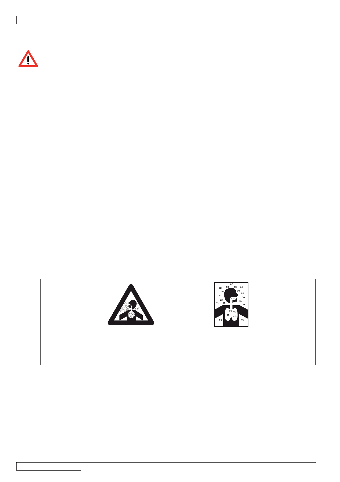
Kohlenmonoxid (CO) kann Gehirnschäden verursachen oder zum Tod führen.
Der Verbrennungsmotor dieses Fahrzeugs stößt Kohlenmonoxid aus.
Abgasrauch nicht einatmen.
In geschlossenen Räumen nur bei ausreichender Belüftung und in Anwesenheit einer Hilfskraft verwenden.
4
1463388000(1)2008-05 A SR 1301 P
Page 7

BETRIEBSANLEITUNG
ACHTUNG!
Vor jeglichen Wartungs-/Reparaturarbeiten alle entsprechenden Anweisungen aufmerksam lesen. –
Angemessene Vorsichtsmaßnahmen ergreifen, damit sich Haare, Schmuckstücke oder weite –
Kleidungsstücke nicht in beweglichen Geräteteilen verfangen können.
Um zu vermeiden, dass das Gerät von Unbefugten verwendet wird, Zündschlüssel abziehen. –
Das unbeaufsichtigte Gerät gegen unbeabsichtigtes Wegrollen sichern. –
Das Gerät nicht auf Oberfl ächen mit einer stärkeren als der auf dem Gerät angegebenen Neigung einsetzen. –
Nur mit dem Gerät gelieferte oder in der Betriebsanleitung angeführte Besen verwenden. Die Verwendung –
anderer Besen kann die Sicherheit beeinträchtigen.
Vor der Verwendung des Geräts sämtliche Klappen und/oder Deckel schließen. –
Das Gerät nicht in stark staubiger Umgebung verwenden. –
Das Gerät nicht mit direktem oder unter Druck stehendem Wasserstrahl oder mit ätzenden Reinigungsmitteln –
reinigen.
Für die allgemeine Reinigung dieses Gerätetyps, außer für Filter, keinen Druckluftstrahl verwenden (siehe –
entsprechenden Abschnitt).
Bei der Verwendung dieses Gerätes darauf achten, dass weder Personen- noch Sachschäden entstehen. –
Achten Sie insbesondere auf Kinder.
Keine Flüssigkeitsbehälter auf dem Gerät abstellen. –
Die Lagertemperatur des Geräts muss zwischen 0 °C und +40 °C liegen. –
Das Gerät nur bei Temperaturen zwischen 0 °C und +40 °C verwenden. –
Die Luftfeuchtigkeit muss zwischen 30 % und 95 % betragen. –
Das Gerät sowohl während des Betriebs als auch bei Stillstand stets vor Sonne, Regen und anderen –
Witterungen schützen. Das Gerät in trockenen geschützten Räumen abstellen: Dieses Gerät ist nur für den
Trockenbetrieb geeignet und darf nicht unter feuchten Bedingungen in Außenbereichen eingesetzt oder
abgestellt werden.
Das Gerät nicht als Transportmittel oder als Schlepp-/Schubfahrzeug verwenden. –
Die Höchstlast des Geräts beträgt zusätzlich zum Gewicht der Bedienperson 110 kg (Gewicht der Abfälle). –
Zur Vermeidung von Schäden am Fußboden Besen bei stehendem Gerät nicht in Betrieb lassen. –
Im Brandfall möglichst einen Pulverlöscher und keinen Wasserlöscher verwenden. –
Nicht gegen Regale und Baugerüste stoßen, insbesondere Gegenständen herunterfallen könnten. –
Die Fahrgeschwindigkeit an die jeweilige Bodenbeschaffenheit anpassen. –
Das Gerät nicht auf Rampen oder geneigten Flächen mit einem stärkeren als dem angegebenen Gefälle –
einsetzen.
Dieses Gerät ist nicht für den Einsatz auf öffentlichen Straßen oder Wegen zugelassen. –
Die Schutzvorrichtungen des Gerätes keinesfalls beschädigen. –
Alle Anweisungen zur ordentlichen Wartung sind gewissenhaft zu befolgen. –
Die am Gerät angebrachten Hinweisschilder nicht entfernen oder verändern. –
Bei Funktionsstörungen sicherstellen, dass diese nicht durch mangelnde Wartung verursacht wurden. –
Gegebenenfalls Fachpersonal bzw. autorisierten Kundendienst benachrichtigen.
Müssen Bauteile ausgewechselt werden, stets beim Kundendienst oder einem autorisierten Vertragshändler –
ORIGINALERSATZTEILE anfordern.
Zur Gewährleistung von Sicherheit und Leistung die im entsprechenden Kapitel dieser Betriebsanleitung –
vorgesehene planmäßige Wartung von Fachpersonal oder einem autorisierten Kundendienst durchführen
lassen.
Das Gerät enthält giftige und schädliche Stoffe (Batterien, Öle, Kunststoffe etc.), für die eine Entsorgung –
durch entsprechende Stellen (siehe Kapitel „Verschrottung“) gesetzlich vorgeschrieben ist. Fahrzeug am
Ende seiner Lebensdauer vorschriftsmäßig entsorgen!
Bei laufendem Motor erwärmt sich der Schalldämpfer. Zur Vermeidung von schweren Verbrennungen und –
Bränden heißen Schalldämpfer nicht berühren.
Wird der Motor bei zu geringem Ölstand laufen gelassen, kann das schwere Motorschäden zur Folge haben. –
Ölstand bei ausgeschaltetem Motor und eben abgestelltem Gerät prüfen.
Zur Vermeidung von Schäden Motor nie ohne Luftfi lter laufen lassen. –
Technische Servicearbeiten am Motor müssen von einem autorisierten Vertragshändler durchgeführt –
werden.
Für den Motor nur Originalersatzteile oder gleichwertige Teile verwenden. Ersatzteile minderer Qualität
können schwere Motorschäden verursachen.
Siehe auch die im Handbuch des Benzinmotors angeführten SICHERHEITSVORSCHRIFTEN, das als –
Bestandteil dieser Betriebsanleitung zu betrachten ist.
DEUTSCH
SR 1301 P 1463388000(1)2008-05 A
5
Page 8

DEUTSCH
BETRIEBSANLEITUNG
GERÄTEBESCHREIBUNG
GERÄTEAUFBAU
Schild Seriennummer/technische Daten/1.
Konformitätszeichen
Rundumkennleuchte (bei Zündschlüssel in Stellung I 2.
immer in Betrieb) (optional)
Deckel Ansauganlagenmotor3.
Abfallbehälter (ist er voll, entleeren)4.
Klappe links (nur für Wartungsarbeiten zu öffnen)5.
Verriegelung links mit Sicherungsschrauben6.
Klappe rechts (zum Ausbau der Hauptkehrwalze)7.
Verriegelung rechts8.
Arbeitsscheinwerfer (optional)9.
Seitenbesen rechts10.
Seitenbesen links (optional)11.
Hauptkehrwalze12.
Motorhaube13.
Antriebsräder hinten, auf feststehender Achse14.
Vorderrad, lenkbar15.
Seitliche Schmutzfangklappe links16.
Seitliche Schmutzfangklappe rechts17.
Schmutzfangklappe vorn18.
Schmutzfangklappe hinten19.
Behälter Staubfi lter20.
Einstellschraube Arbeitsscheinwerfer ausrichten21.
Abgaskrümmer22.
Motorhaube (offen)23.
Batterie24.
Flachsicherungskasten25.
Stecker Ansauganlagenmotor26.
Pumpe Antriebsanlage27.
Öltank Antriebsanlage28.
Benzinmotor29.
Kraftstofftank30.
Kraftstofftankdeckel31.
Motorluftfi lter32.
Modell und Seriennummer Benzinmotor33.
Deckel Motorölstand34.
Deckel Motoröleinfüllstutzen35.
Einankerumformer36.
Entriegelungsschraube Hydraulikpumpe (für leichteres 37.
Schieben/Schleppen des Geräts bei fehlendem Antrieb)
Motorölablassschraube38.
Relais Motorstart39.
Motorölablassrohr40.
Öltank hydraulische Hubanlage Abfallbehälter41.
Relais Betätigung Hebepumpe Abfallbehälter42.
Antriebsanlagenmotoren43.
Schutzabdeckung Benzinmotor44.
Befestigungsschrauben Schutzabdeckung45.
Haltevorrichtung Schutzabdeckung46.
Seitliche Schutzplatte links47.
Befestigungsschrauben Schutzplatte48.
Haltevorrichtung Schutzplatte
49.
Sicherung Ladesystem50.
Zündkerze51.
Motorschalldämpfer52.
Abgasendrohr53.
Fahrersitz54.
Stützstange Haube55.
Diode56.
Anschlussplan Batterien57.
13254
10 9 15 11 18 6 16 5 14
21
3
20
9
1
4
19
14
12
17
8
7
P100206
6
1463388000(1)2008-05 A SR 1301 P
Page 9

GERÄTEAUFBAU (Fortsetzung)
BETRIEBSANLEITUNG
44
DEUTSCH
39
56
50
27
37
31
43
45
41
30
33
26
42
22
46
25
28
35
52
53
43
57
24
12V
12V
36
55
34
51
29
38-40
48
47
49
32
23
P100207
SR 1301 P 1463388000(1)2008-05 A
7
Page 10
DEUTSCH
BETRIEBSANLEITUNG
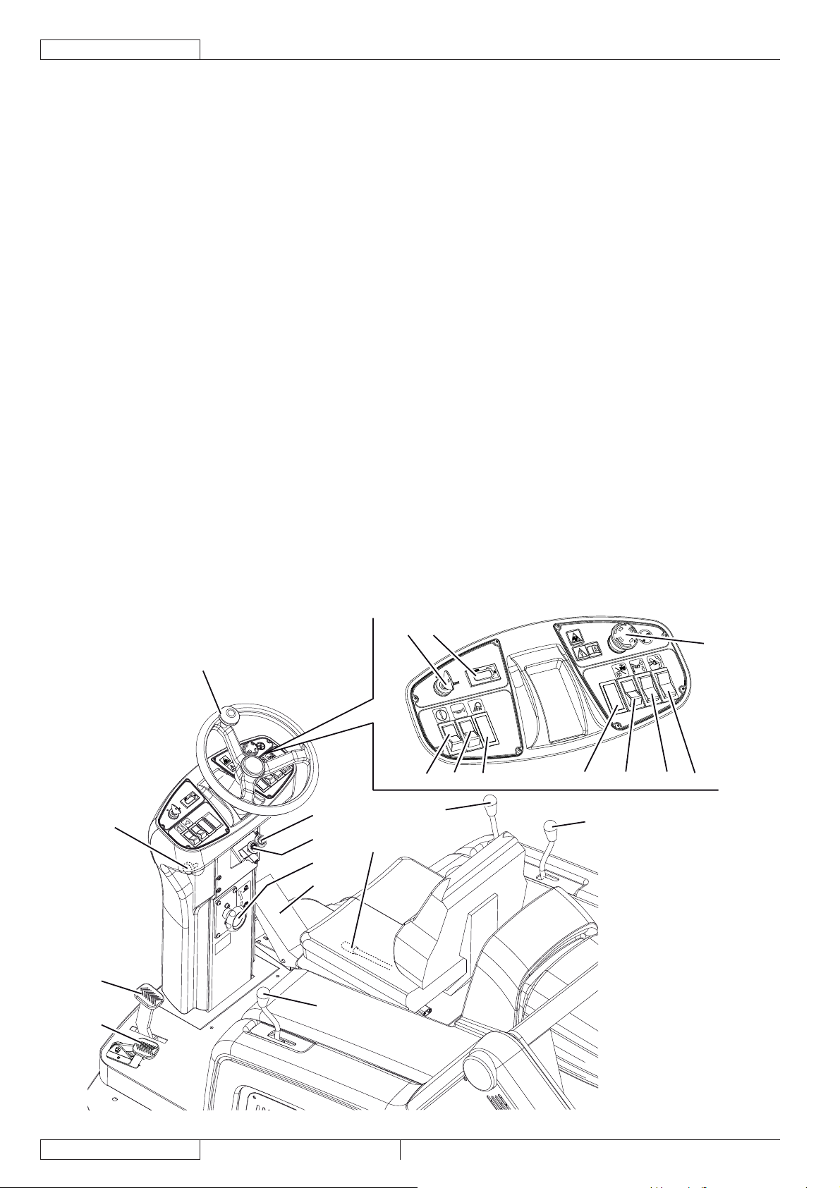
BEDIENPULT UND BEDIENELEMENTE
Freigabeschalter Abfallbehälter anheben/absenken und 61.
kippen
Schalter Hupe62.
Leerplatz für Schalter Arbeitsscheinwerfer (optional)63.
Drehregler Hauptkehrwalzenspur64.
Zur Vergrößerung der Besenspur gegen den •
Uhrzeigersinn drehen
Zur Verkleinerung der Besenspur im Uhrzeigersinn •
drehen
Leerplatz für optionalen Schalter65.
Schalter66.
(Untere Stellung) Ansauganlage einschalten•
(Obere Stellung) Filterrüttler einschalten•
Schalter Abfallbehälter anheben/absenken67.
Schalter Abfallbehälter kippen68.
Zündschlüssel69.
In Stellung 0 werden der Benzinmotor sowie alle •
Gerätefunktionen ausgeschaltet.
In Stellung I werden die verschiedenen •
Gerätefunktionen freigegeben und die
Rundumkennleuchte wird eingeschaltet.
Im Uhrzeigersinn bis zum Anschlag in Stellung „Start“ •
gedreht wird der Benzinmotor gestartet. Springt der
Motor an, Zündschlüssel loslassen. Der Zündschlüssel
kehrt in Stellung I zurück.
Betriebsstundenzähler70.
Not-Aus-Knopf. Im Notfall zum Abschalten sämtlicher 71.
Gerätefunktionen betätigen. Um den Not-Aus-Knopf nach
der Betätigung wieder zu deaktivieren, in Richtung des auf
dem Knopf abgebildeten Pfeils drehen.
Lenkrad72.
Drehregler Lenkradneigung73.
Kaltstarteinrichtung74.
Einstellhebel Feststellbremse sperren. Sperrt 75.
die Betriebsbremse (82) und funktioniert sie zur
Feststellbremse um.
Vorwärts-/Rückwärtsgangpedal76.
Hebel rechten Seitenbesen anheben/absenken77.
Hebel linken Seitenbesen (optional) anheben/absenken78.
Einstellhebel Längsposition Sitz79.
Hebel Hauptkehrwalze anheben/absenken80.
Pedal vordere Schmutzfangklappe81.
Bremspedal82.
82
81
73
72
74
75
64
76
80
79
69
70
61 62
77
71
63 65 66 67 68
78
P100208
8
1463388000(1)2008-05 A SR 1301 P
Page 11

BETRIEBSANLEITUNG
DEUTSCH
ZUBEHÖR/SONDERAUSSTATTUNG
Neben den mit der Grundausführung gelieferten Bauteilen sind je nach spezifi scher Verwendung des Gerätes folgendes Zubehör
und folgende Sonderausstattungen lieferbar:
Seitenbesen links –
Hauptkehrwalzen und Seitenbesen mit härteren oder weicheren Borsten als die Standardborsten –
Staubfi lter aus antistatischem Polyester und Polyester BIA C –
Taschenfi lter (Staubfi lter) –
Rundumkennleuchte –
Arbeitsscheinwerfer –
Nicht kreidende Schmutzfangklappe –
Nicht kreidende Räder –
Schutzdach –
Bitte setzen Sie sich für weitere Informationen zu den obengenannten Zubehörteilen/Sonderaustattungen mit einem Händler Ihrer
Wahl in Verbindung.
TECHNISCHE DATEN
Allgemein Werte
Arbeitsbreite (mit einem Seitenbesen) 1.054 mm
Arbeitsbreite (mit zwei Seitenbesen) 1.308 mm
Gerätelänge 1.776 mm
Gerätebreite (mit einem Seitenbesen) 1.208 mm
Gerätebreite (mit zwei Seitenbesen) 1.310 mm
Maximale Gerätehöhe (am Lenkrad) 1.350 mm
Mindestbodenfreiheit (außer Schmutzfangklappen) 60 mm
Maximale Hubhöhe Abfallbehälter 1.650 mm
Minimale/maximale Entleerhöhe 270/1.370 mm
Mindestlenkradius 1.685 mm
Maße Hauptkehrwalze (Durchmesser x Länge) 300 x 800 mm
Durchmesser Seitenbesen 500 mm
Höchstgeschwindigkeit im Vorwärtsgang 7 km/h
Höchstgeschwindigkeit im Rückwärtsgang 3 km/h
Maximale Steigfähigkeit 20%
Kapazität Abfallbehälter 130 Liter
Maximales Hubgewicht Abfallbehälter 110 kg
Vorderachsdruck unter Fahrbedingungen 297 kg
Hinterachsdruck unter Fahrbedingungen 446 kg
Gesamtgewicht unter Fahrbedienung (mit Bedienperson) 743 kg
Spezifi scher Bodendruck Hinterräder 1,2 N/mm
Spezifi scher Bodendruck Vorderrad 1,1 N/mm
Lenkbares Vorderrad (Durchmesser x Länge) 305 x 92 mm
Hintere Antriebsräder (Durchmesser x Länge) 305 x 92 mm
Schalldruckpegel am Ohr der Bedienperson (ISO 11201, ISO 4871) (LpA) 80 dB(A) ± 3 dB(A)
Vom Gerät emittierter Schallleistungspegel (ISO 3744, ISO 4871) (LwA) 98 dB(A)
Schwingungspegel am Arm der Bedienperson (ISO 5349-1) (*) < 2,5 m/s
Pegel der auf die Bedienperson übertragenen Schwingungen (ISO 2631-1) (*) < 0,5 m/s
(*) Bei normalen Arbeitsbedingungen auf einer ebenen Asphaltfl äche.
2
2
2
2
Benzinmotor (*) Daten
Marke Briggs & Stratton
Modell Vanguard 9 HP
Geregelte Motorleistung (ISO 1585) 6,7 kW
Drehzahl im Kehrbetrieb 3.100 ± 50 U/min
Durchschnittsverbrauch 1,7 Liter/Stunde
Kapazität Kraftstofftank 8,5 Liter
Verwendeter Öltyp SAE 5 W 30 - SYNTHETISCH API SJ
(*) Für die anderen Daten/Werte des Benzinmotors siehe entsprechendes Handbuch.
SR 1301 P 1463388000(1)2008-05 A
9
Page 12

DEUTSCH
BETRIEBSANLEITUNG
Staubansaugung und -fi lterung Werte
Papierstaubfi lter 15-20 m 3,6 m
2
Unterdruck Hauptkehrwalzenraum 10,9 mm/H2O
Elektrik Werte
Batterien 2 x 12 V – 70 Ah
Ansauganlagenmotor 310 W, 3000 U/min
Hauptkehrwalzenmotor 500 W, 550 U/min
Filterrüttlermotor 90 W, 5700 U/min
Filterrüttlermotor für Taschenfi lter (optional) 110 W, 3000 U/min
Hydraulische Antriebsanlage Werte
Pumpe Antriebsanlage SAUER HIDRO-GEAR BDP 10A
Volumen Antriebsanlagenpumpe 10,2 cm
Volumen Füllpumpe 1,9 cm
3
3
Maximaler Anpressdruck beim Kehren 70 bar
Maximale Druckspitze 145 bar
Kapazität Öltank Hydraulikanlage 0,8 Liter
Gesamtkapazität Hydraulikkreislauf 1,2 Liter
Verwendeter Öltyp SAE 10 W 40
Hydraulische Hubanlage Abfallbehälter Werte
Pumpe Parker 108 AE S32 – 24 V
Höchstdruck 110 bar
Kapazität Öltank 0,75 Liter
Gesamtkapazität Hydraulikkreislauf 1,4 Liter
Hydraulikanlagenöl (bei Umgebungstemperatur über 10 °C) AGIP Arnica 46 (*)
HINWEIS!
Wird das Gerät bei einer Umgebungstemperatur unter +10 °C verwendet, wird empfohlen, das Öl gegen ein
gleichwertiges Öl mit einer Viskosität von 32 cSt auszutauschen. Für Temperaturen unter 0°C ein Öl mit einer
noch niedrigeren Viskosität verwenden.
(*) Siehe nachstehende Tabellen der Öleigenschaften und der Bezugsspezifi kationen.
TECHNISCHE DATEN BEZUGSSPEZIFIKATIONEN
AGIP ARNICA 46 32 ISO-L-HV
Viskosität bei 40°C mm
Viskosität bei 100°C mm
Viskositätsindex / 150 157 AISE 127
Flammpunkt COC °C 215 202 ATOS Tab. P 002-0/I
Fließpunkt °C -36 -36 BS 4231 HSE
Dichte bei 15 °C kg/L 0,87 0,865 CETOP RP 91 H HV
2
/s 45 32 ISO 11158
2
/s 7,97 6,40 AFNOR NF E 48603 HV
COMMERCIAL HYDRAULICS
Danieli Standard 0.000.001 (AGIP ARNICA 22, 46, 68)
EATON VICKERS I-286-S3
EATON VICKERS M-2950
DIN 51524 t.3 HVLP
LAMB LANDIS-CINCINNATI P68, P69, P70
LINDE
PARKER HANNIFIN (DENISON) HF-0
REXROTH RE 90220-1/11.02
SAUER-DANFOSS 520L0463
10
1463388000(1)2008-05 A SR 1301 P
Page 13

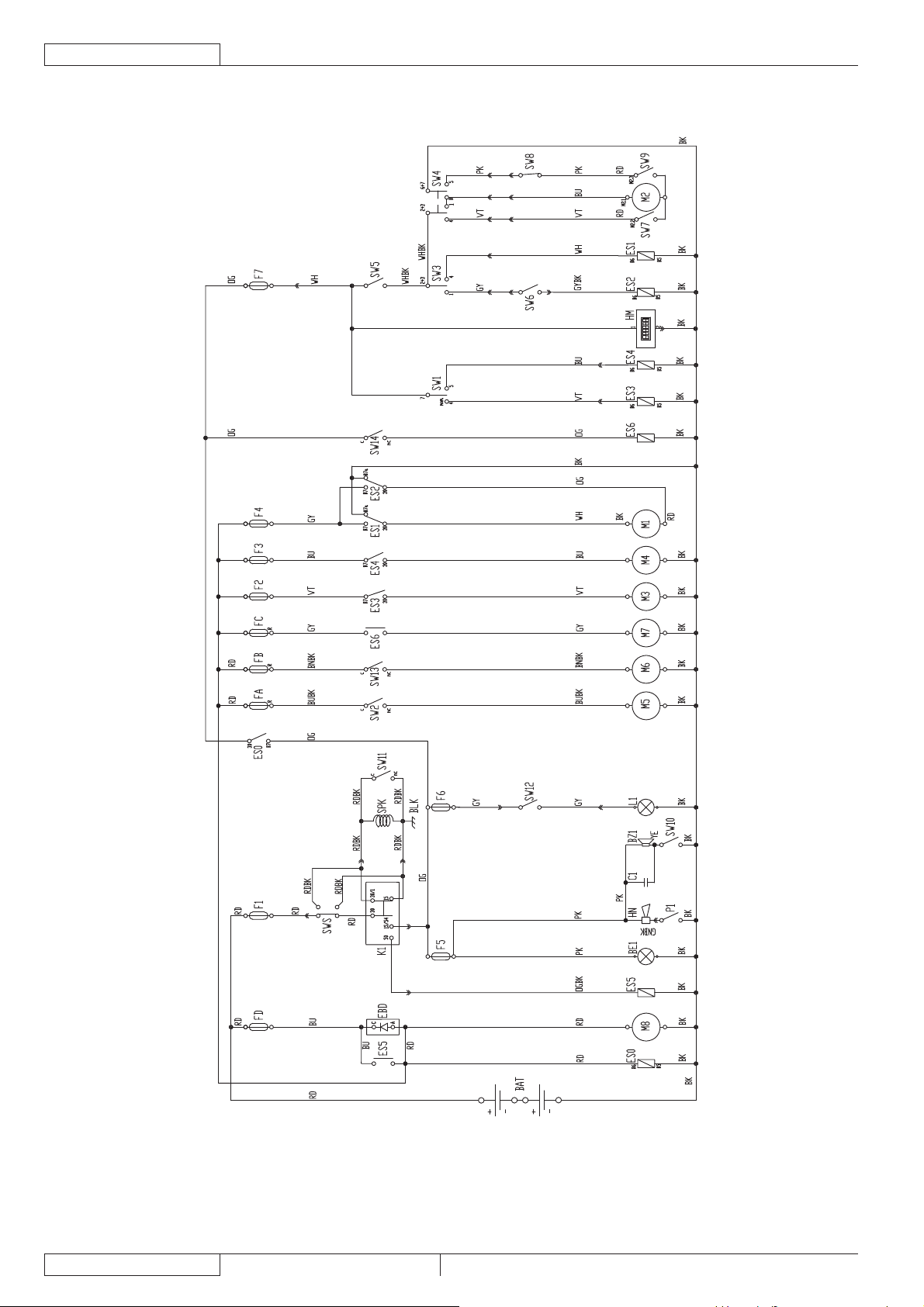
SCHALTPLAN
Legende
BAT 24-V-Batterie
BE1 Rundumkennleuchte (optional)
BLK Rahmen Benzinmotor
BZ1 Rückfahralarm - Alarm
C1 Kondensator Rückfahralarm
EBD Diodenplatine
ES0 Relais Motor läuft
ES1 Pumpenrelais Abfallbehälter anheben
ES2 Pumpenrelais Abfallbehälter absenken
ES3 Relais Filterrüttler
ES4 Relais Ansauganlage
ES5 Startrelais
ES6 Fernschalter Hauptkehrwalze
FA Selbstrückstellende Sicherung rechter Seitenbesen (10 A)
Selbstrückstellende Sicherung linker Seitenbesen (optional)
FB
(10 A)
FC Selbstrückstellende Sicherung Hauptkehrwalze (30 A)
FD Sicherung Ladesystem (70 A)
F1 Sicherung Schlüssel (30 A)
F2 Sicherung Filterrüttler (30 A)
F3 Sicherung Ansauganlage (30 A)
F4 Sicherung Hebepumpe Abfallbehälter (30 A)
F5 Sicherung Rückfahralarm und Rundumkennleuchte (10 A)
F6 Sicherung Arbeitsscheinwerfer (10 A)
F7 Sicherung Stellantrieb Abfallbehälter kippen (10 A)
HM Betriebsstundenzähler
K1 Zündschlüssel
L1 Arbeitsscheinwerfer (optional)
M1 Hebepumpe Abfallbehälter
M2 Stellantrieb Abfallbehälter kippen
M3 Filterrüttlermotor
M4 Ansauganlagenmotor
M5 Motor rechter Seitenbesen
M6 Motor linker Seitenbesen (optional)
M7 Hauptkehrwalzenmotor
M8 Dynamo
P1 Schalter Hupe
SPK Kerze Benzinmotor
SW1 Schalter Ansauganlage/Filterrüttler
SW2 Mikroschalter rechter Seitenbesen
SW3 Schalter Abfallbehälter anheben/absenken
SW4 Schalter Abfallbehälter kippen
SW5 Freigabeschalter Abfallbehälter bewegen
SW6 Mikroschalter Abfallbehälter in Horizontalstellung
SW7 Mikroschalter Abfallbehälter vollständig geschlossen
SW8 Mikroschalter Abfallbehälter angehoben
SW9 Mikroschalter Abfallbehälter vollständig geöffnet
SW10 Mikroschalter Rückwärtsgang
SW11 Mikroschalter Haube geöffnet
SW12 Schalter Arbeitsscheinwerfer (optional)
SW13 Mikroschalter linker Seitenbesen (optional)
SW14 Mikroschalter Hauptkehrwalze
SWS Not-Aus-Knopf
BETRIEBSANLEITUNG
Farbcodes
BK Schwarz
BU Hellblau
BN Braun
GN Grün
GY Grau
OG Orange
PK Rosa
RD Rot
VT Violett
WH Weiß
YE Gelb
DEUTSCH
SR 1301 P 1463388000(1)2008-05 A
11
Page 14
DEUTSCH
BETRIEBSANLEITUNG
SCHALTPLAN (Fortsetzung)
12
P100209
1463388000(1)2008-05 A SR 1301 P
Page 15
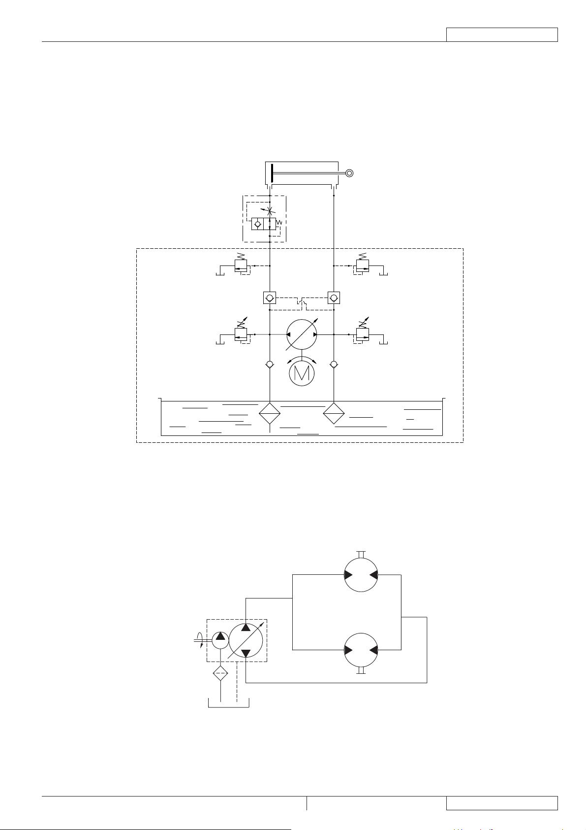
HYDRAULIKPLAN DER ABFALLBEHÄLTERHUBANLAGE
Legende
Öltank1.
Ölfi lter2.
Pumpe3.
Motor4.
Absperrventil Hubzylinder5.
Hubzylinder Abfallbehälter6.
6
5
BETRIEBSANLEITUNG
DEUTSCH
200 BAR
110 BAR
750cc / HYDRAULIC OIL 32 cSt
1
HYDRAULIKPLAN DER ANTRIEBSANLAGE
Legende
Öltank1.
Ölfi lter2.
Pumpe3.
Motoren4.
200 BAR
3
70 BAR
4
2
P100210
4
3000
RPM
100
MICRON
10,2 CC/REV.
2
AB
88 CC/REV.
A
88 CC/REV.
3
A
B
4
B
1
SR 1301 P 1463388000(1)2008-05 A
P100211
13
Page 16
DEUTSCH
BETRIEB
BETRIEBSANLEITUNG
72
54
79
69
71
80
73
82
81
31
78
75
66
74
77
10 11
18
76
12
P100212
ACHTUNG!
An einigen Stellen des Geräts sind folgende Aufkleber angebracht:
GEFAHR –
ACHTUNG –
HINWEIS –
NACHSCHLAGEN –
Während des Lesens dieser Anleitung hat sich die Bedienperson die Bedeutung der auf den Aufklebern abgebildeten Symbole
einzuprägen.
Die Schilder keinesfalls abdecken und bei Beschädigung sofort ersetzen.
VOR DEM EINSCHALTEN DES GERÄTS
Falls erforderlich, Tankdeckel (31) abschrauben und Kraftstoff tanken.1.
ACHTUNG!
Damit sich der Kraftstoff ausdehnen kann, den Tank nicht vollständig füllen, sondern mindestens 4 cm Platz
zum Rand des Einfüllstutzens lassen.
Prüfen, ob keine Klappen/Hauben am Gerät geöffnet sind und ob normale Betriebsbedingungen vorliegen.2.
Ist das Gerät nach einem Transport noch nicht eingesetzt worden, prüfen, ob alle zum Transport verwendeten 3.
Sicherungsklötze und Arretiervorrichtungen entfernt wurden.
GERÄT EINSCHALTEN UND ABSTELLEN
Gerät einschalten
Auf den Fahrersitz (54) setzen und mit dem Hebel (79) die gewünschte Sitzstellung einstellen.1.
Drehregler (73) herausziehen und gewünschte Lenkradneigung (72) einstellen. Nach dem Einstellen Drehregler (73) loslassen 2.
und das Lenkrad leicht bewegen, damit die interne Haltevorrichtung einrasten kann.
Feststellbremse mit dem Pedal (82) und dem Hebel (75) betätigen.3.
Hauptkehrwalze und Seitenbesen mit den entsprechenden Hebeln (80), (77), (78) anheben.4.
Hebel der Kaltstarteinrichtung (74) herausziehen.5.
HINWEIS
Hebel der Kaltstarteinrichtung nicht betätigen, wenn der Motor warm und die Lufttemperatur ausreichend hoch ist.
Benzinmotor mit dem Zündschlüssel (69) starten. Unverzüglich den Zündschlüssel loslassen, sobald der Motor anspringt.6.
ACHTUNG!
Während des Anlassens mit dem Zündschlüssel (69) Fahrpedal (76) nicht betätigen.
14
1463388000(1)2008-05 A SR 1301 P
Page 17

BETRIEBSANLEITUNG
Nach der Zündung Motor für einige Sekunden laufen lassen und Kaltstarteinrichtung (74) abschalten.7.
Motor einige Minuten warm werden lassen.8.
Feststellbremse durch Betätigen des Pedals (82) und gleichzeitiges Lösen des Hebel (75) lösen.9.
Mit den Händen am Lenkrad (72) Gerät durch Betätigen des Pedals (76) anfahren: Pedal zur Vorwärtsfahrt vorne und zur 10.
Rückwärtsfahrt hinten treten. An den Ort fahren, an dem mit dem Reinigen begonnen werden soll.
Die Fahrgeschwindigkeit kann, je nach Stärke des Drucks auf das Pedal, von Null bis zur Höchstgeschwindigkeit reguliert
werden.
Mit dem Hebel (80) Hauptkehrwalze absenken und Sauganlage durch Betätigen der unteren Hälfte des Schalters (66) 11.
einschalten.
Mit dem Hebel (77) rechten Seitenbesen absenken.12.
Falls vorhanden, linken Seitenbesen mit dem Hebel (78) absenken.13.
HINWEIS
Hauptkehrwalze (12) und Seitenbesen (10, 11) können auch bei fahrendem Gerät abgesenkt und angehoben werden.
Hauptkehrwalze und Seitenbesen drehen sich nicht, wenn sie angehoben sind.
Das Gerät durch Betätigen des Pedals (76) und mit den Händen am Lenkrad (72) anfahren und mit dem Kehren beginnen.14.
DEUTSCH
Gerät abstellen
Zum Anhalten des Geräts Pedal (76) loslassen.15.
Um die Kehrmaschine schnell anzuhalten, zusätzlich Bremspedal (82) treten.
Um das Gerät im Notfall sofort anzuhalten, Not-Aus-Knopf (71) betätigen.
Um den Not-Aus-Knopf (71) nach der Betätigung wieder zu deaktivieren, in Richtung des auf dem Knopf abgebildeten Pfeils
drehen.
Hauptkehrwalze und Seitenbesen mit den entsprechenden Hebeln (80), (77), (78) anheben.16.
Schalter (66) betätigen und Ansauganlage ausschalten.17.
Gerät durch Drehen des Zündschlüssels (69) in Stellung 0 ausschalten und Schlüssel abziehen.18.
Feststellbremse durch Drücken des Pedals (82) und gleichzeitiges Betätigen des Hebels zum Sperren der Bremse (75) 19.
aktivieren.
GERÄT IM KEHRBETRIEB
Seitenbesen und Hauptkehrwalze nicht zu lange bei stehendem Gerät rotieren lassen: Der Fußboden könnte beschädigt 1.
werden.
Zum Aufsammeln leichter und großvolumiger Abfälle vordere Schmutzfangklappe (18) durch Betätigen des Pedals (81) 2.
anheben. Die Saugfähigkeit des Geräts ist bei angehobener vorderer Schmutzfangklappe vermindert.
ACHTUNG!
Wird auf nassem Boden gekehrt, muss die Ansauganlage zum Schutz des Staubfi lters unbedingt durch
Betätigen des Schalters (66) ausgeschaltet werden.
Für ein gutes Kehrergebnis muss der Staubfi lter so sauber wie möglich sein. Um den Staubfi lter während des Kehrens zu 3.
reinigen, Filterrüttler durch Drücken der oberen Hälfte des Schalters (66) kurz betätigen. Ansauganlage durch Drücken der
unteren Hälfte des Schalters (66) wieder einschalten.
Während des Kehrens ca. alle 10 Minuten (in Abhängigkeit von der Staubkonzentration im Kehrbereich) wiederholen.
HINWEIS
Dieser Vorgang kann auch bei fahrendem Gerät durchgeführt werden.
HINWEIS!
Ist der Staubfi lter verstopft und/oder der Abfallbehälter voll, kann die Kehrmaschine Staub und Abfälle nicht
mehr aufnehmen.
Am Arbeitsende und bei vollem Abfallbehälter (4) Abfallbehälter leeren (für die entsprechenden Arbeitschritte siehe 4.
nachstehenden Abschnitt).
HINWEIS!
Der Benzinmotor verfügt über ein Alarmsystem, um bei zu wenig Öl im Kurbelgehäuse Motorschäden zu
vermeiden. Bevor das Öl im Kurbelgehäuse die Sicherheitsgrenze unterschreitet, schaltet das Alarmsystem den
Motor selbsttätig ab.
SR 1301 P 1463388000(1)2008-05 A
15
Page 18
DEUTSCH
BETRIEBSANLEITUNG
ENTLEERUNG DES ABFALLBEHÄLTERS
4
ACHTUNG!
Abfallbehälter immer bei laufendem Motor entleeren.
Um zu vermeiden, dass sich die Batterien entlädt, Abfallbehälter nicht bei ausgeschaltetem Motor entleeren.
Die maximale Entleerhöhe des Abfallbehälters beträgt 1.370 mm (siehe Abb. 2).1.
Zum Entleeren in die Nähe des Abfallcontainers fahren und wie folgt vorgehen:2.
Seitenbesen und Hauptkehrwalze anheben.•
Schalter (66) betätigen und Ansauganlage ausschalten.•
Die obere Hälfte des Schalters (66) drücken und Filterrüttler betätigen.•
ACHTUNG!
Zur Gewährleistung der Gerätestabilität Entleerung immer auf ebenem Untergrund vornehmen.
82
81
75
61
68
67
66
P100213
ACHTUNG!
Während des Anhebens und Entleerens des Abfallbehälters (4) Feststellbremse mit dem Pedal (82) und dem
Hebel (75) betätigt lassen.
Es dürfen sich keine Personen in der Nähe des Geräts, insbesondere nicht im Bereich des Abfallbehälters (4) aufhalten.3.
Freigabeschalter (61) und gleichzeitig Schalter zum Anheben des Abfallbehälters (67) betätigen und Abfallbehälter bis zur 4.
gewünschten Höhe anheben (A, Abb. 1).
Freigabeschalter (61) und gleichzeitig Schalter zum Kippen (68) des Abfallbehälters (B, Abb. 2) betätigen und alle Abfälle in 5.
den Abfallcontainer (A) entleeren.
HINWEIS!
Das Gerät ermöglicht das Kippen des Abfallbehälters (B, Abb. 2) erst ab einer Mindesthöhe von 270 mm.
Freigabeschalter (61) und gleichzeitig Schalter zum Kippen des Abfallbehälters (68) betätigen, um den Abfallbehälter wieder in 6.
Horizontalstellung zu bringen.
Zum vollständigen Absenken des Abfallbehälters Freigabeschalter (61) und gleichzeitig Schalter zum Absenken des 7.
Abfallbehälters (67) betätigen.
HINWEIS!
Der Abfallbehälter kann nur abgesenkt werden, wenn er vorher in Horizontalstellung gebracht wurde.
Das Gerät kann jetzt wieder zum Kehren eingesetzt werden.8.
A
B
A
16
P max
110 Kg
(242,5 lb)
1370 mm (54 in)
P100214 P100215
Abbildung 1 Abbildung 2
1463388000(1)2008-05 A SR 1301 P
Page 19

BETRIEBSANLEITUNG
NACH DER GERÄTEBENUTZUNG
Am Arbeitsende vor dem Abstellen des Geräts:
Die obere Hälfte des Schalters (66) drücken und Filterrüttler kurz betätigen. –
Abfallbehälter (4) entleeren (siehe vorstehenden Abschnitt). –
Hauptkehrwalze mit dem Hebel (80) anheben. –
Seitenbesen mit den Hebeln (77) und (78) anheben. –
Gerät durch Drehen des Zündschlüssels (69) in Stellung 0 ausschalten und Schlüssel abziehen. –
Feststellbremse durch Drücken des Pedals (82) und gleichzeitiges Betätigen des Hebels zum Sperren der Bremse (75) –
aktivieren.
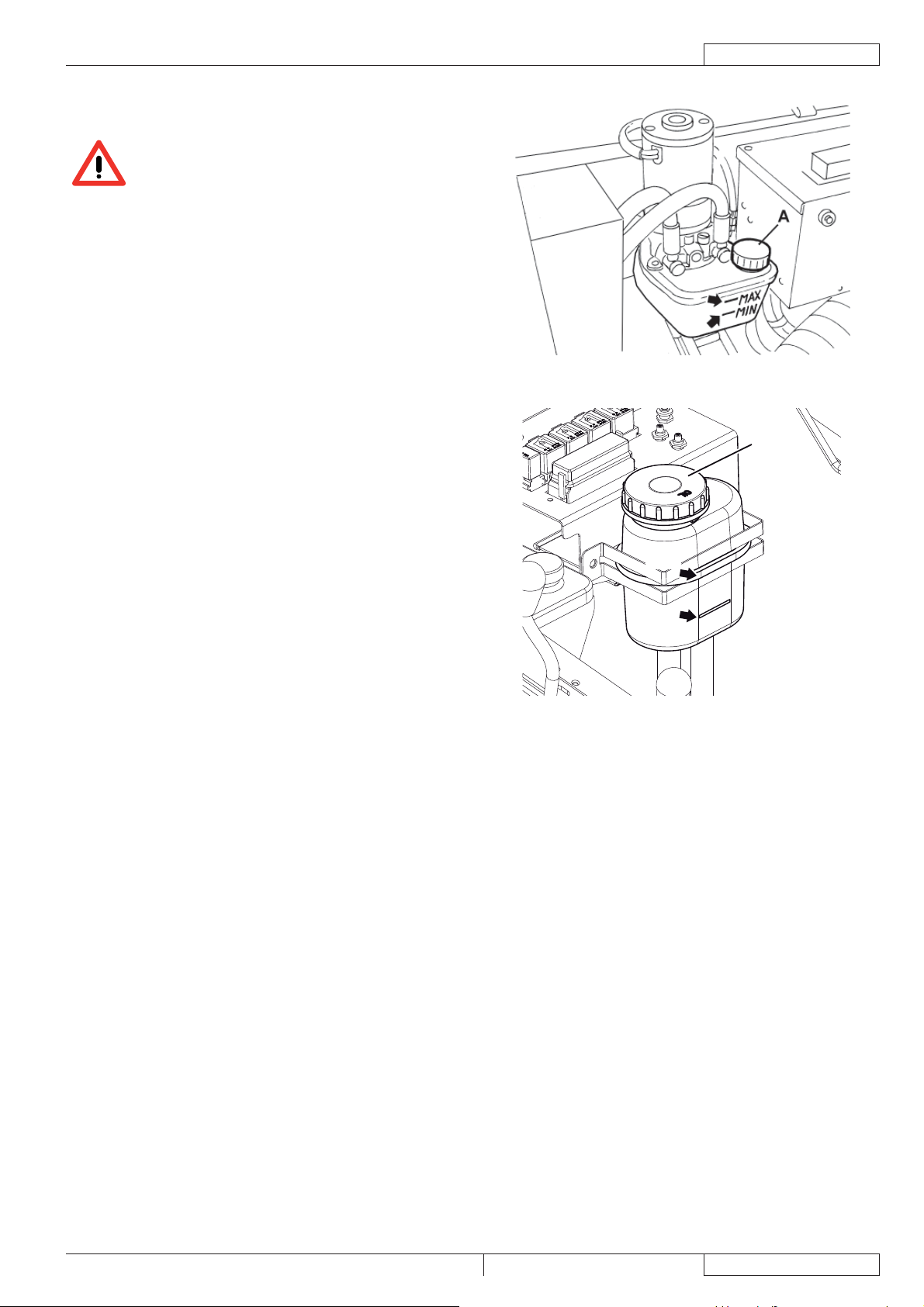
GERÄT SCHIEBEN/ABSCHLEPPEN
Zum Schieben/Abschleppen des ausgeschalteten Geräts folgendermaßen vorgehen:
Zündschlüssel (69) in Stellung 0 drehen und Gerät ausschalten. –
Haube (23) öffnen und mit der Stützstange (55) sichern. –
Schraube (37) entfernen. –
Stützstange (55) abnehmen und Haube (23) schließen. –
Gerät schieben/abschleppen. –
Nach dem Schieben/Abschleppen Schraube (37) eindrehen. –
ARBEITSSCHEINWERFER (optional) EINSTELLEN
Lichtstrahl des Arbeitsscheinwerfers (9) gegebenenfalls mit den Schrauben (21) einstellen.
LANGE STILLLEGUNG DES GERÄTS
Wird das Gerät für mehr als 30 Tage nicht verwendet, Gerät wie folgt vorbereiten:
Prüfen, ob der für das Gerät vorgesehene Lagerort trocken und sauber ist.1.
Minuspol (-) der Batterien (24) trennen.2.
Benzinmotor (29) wie im entsprechenden Handbuch vorgesehen vorbereiten.3.
DEUTSCH
ERSTE BETRIEBSZEIT
Nach der ersten Verwendungsphase (den ersten 5 Stunden) ist es erforderlich:
Zu prüfen, ob Befestigungs- und Verbindungselemente fest angezogen sind und ob die sichtbaren Teile keine Schäden 1.
aufweisen und nicht undicht sind.
Öl des Benzinmotors wechseln (siehe Kapitel „Wartung“).2.
SR 1301 P 1463388000(1)2008-05 A
17
Page 20

DEUTSCH
BETRIEBSANLEITUNG
WARTUNG
Sorgfältige und regelmäßige Wartung gewährleistet Betriebsdauer und höchste Funktionssicherheit des Geräts.
Nachfolgend wird die Übersichtstabelle planmäßige Wartung wiedergegeben. In Abhängigkeit von bestimmten Arbeitsbedingungen
können die Wartungsintervalle variieren. Sämtliche Abweichungen sind vom Wartungspersonal festzulegen.
Alle planmäßigen oder außerordentlichen Wartungsarbeiten sind von Fachpersonal bzw. vom autorisierten Kundendienst
durchzuführen.
In dieser Betriebsanleitung sind im Anschluss an die Übersichtstabelle planmäßige Wartung nur die einfachsten und häufi gsten
Wartungsarbeiten angeführt.
Für die Arbeitsschritte der anderen Wartungsarbeiten, die in der Übersichtstabelle planmäßige Wartung und außerordentliche
Wartung vorgesehen sind, siehe Service-Anleitung bei den zahlreichen Kundendienststellen.
ACHTUNG!
Wartungsbearbeitungen sind bei ausgeschaltetem Gerät, abgezogenem Zündschlüssel und, falls erforderlich,
mit getrennten Batterien durchzuführen.
Vor dem Durchführen von Wartungsarbeiten sämtliche Sicherheitshinweise im Kapitel „Sicherheit“ aufmerksam
lesen.
ÜBERSICHTSTABELLE PLANMÄSSIGE WARTUNG
Nach den
Arbeitsvorgang Bei Lieferung
Motorölstand überprüfen
Batteriefl üssigkeitsstand überprüfen
Seitenbesen- und
Hauptkehrwalzenhöhe überprüfen
Luftvorfi lter des Motors reinigen (3)
Flachfi lter (Staubfi lter) reinigen und
auf Schäden überprüfen
Ölstand der hydraulischen Hubanlage
des Abfallbehälters überprüfen
Ölstand der Antriebsanlage
überprüfen
Höhe und Funktionsfähigkeit der
Schmutzfangklappen überprüfen
Kraftstofffi lter reinigen
Funkenschutz überprüfen und
reinigen
Motoröl auswechseln (2)
Funktionsfähigkeit des Filterrüttlers
überprüfen
Bremsen einstellen (1)
Spannung der Antriebsketten der
Antriebsräder überprüfen und Ketten
reinigen
Taschenfi lter (Staubfi lter) reinigen und
auf Schäden überprüfen
Leistungsfähigkeit der Ansauganlage
überprüfen
Sichtprüfung des Antriebsriemens (1) (1)
ersten 5
Betriebs-
stunden
Alle 10
Stunden
oder vor dem
Betrieb
Alle 25
Stunden
Alle 50
Stunden
Alle 100
Stunden
(1)
(1)
(1)
Alle 200
Stunden
Jährlich
18
1463388000(1)2008-05 A SR 1301 P
Page 21

BETRIEBSANLEITUNG
DEUTSCH
Nach den
Arbeitsvorgang Bei Lieferung
Zündkerze überprüfen/reinigen
Muttern- und Schraubenspannung
überprüfen
Spannung der Lenkkette überprüfen
und Lenkkette reinigen
Funktionsfähigkeit der
Sicherheitseinrichtungen überprüfen
Motordrehzahl überprüfen (1)
Einsatz des Motorluftfi lters warten (3)
Zündkerze auswechseln (2)
Motorkühlsystem reinigen (2)
Antriebsriemen auswechseln (1) (5)
Dichtungen des Abfallbehälters auf
Schäden überprüfen
Einstellung des Mikroschalters
Abfallbehälter angehoben überprüfen
Einstellung des Mikroschalters
Abfallbehälter in Horizontalstellung
überprüfen
Ventilspiel überprüfen/einstellen (4)
Öl der hydraulischen Hubanlage
des Abfallbehälters und der
Antriebsanlage wechseln
ersten 5
Betriebs-
stunden
(1) (1)
Alle 10
Stunden
oder vor dem
Betrieb
Alle 25
Stunden
Alle 50
Stunden
Alle 100
Stunden
(1)
(1)
Alle 200
Stunden
(1)
(1)
(1)
Jährlich
(1) (6)
(1) Für die entsprechenden Arbeitsschritte, siehe Service-Anleitung.
(2) Bzw. jährlich.
(3) Bzw. in staubiger Umgebung häufi ger.
(4) Von einem autorisierten Briggs & Stratton Vertragshändler durchzuführende Wartungsarbeiten.
(5) Falls vom Wartungspersonal als erforderlich erachtet.
(6) Das Hydrauliköl zum ersten Mal nach 500 Betriebsstunden und danach alle 2.000 Stunden bzw. einmal im Jahr auswechseln.
SR 1301 P 1463388000(1)2008-05 A
19
Page 22
DEUTSCH
BETRIEBSANLEITUNG
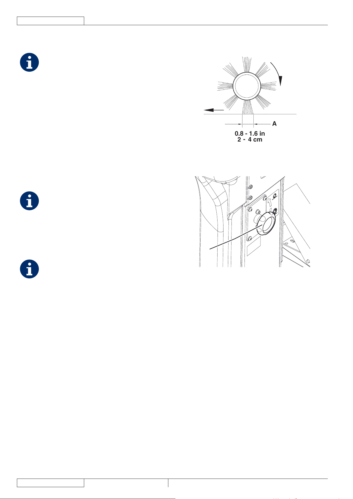
HAUPTKEHRWALZENHÖHE ÜBERPRÜFEN UND
EINSTELLEN
HINWEIS
Es werden Hauptkehrwalzen und Seitenbesen
verschiedener Härtegrade geliefert. Diese
Arbeitsschritte sind bei allen Besen- und
Walzentypen anzuwenden.
Bodenfreiheit der Hauptkehrwalze wie folgt überprüfen:1.
Das Gerät auf ebenem Untergrund abstellen.•
Bei stehendem Gerät die Hauptkehrwalze absenken •
und einige Sekunden drehen lassen.
Hauptkehrwalze anhalten und anheben. Gerät zur •
Seite fahren und ausschalten.
Überprüfen, ob die Hauptkehrwalzenspur (A, Abb. 3) in •
ihrer gesamten Länge 2 bis 4 cm breit ist.
Weicht die Spur (A) ab, die Höhe der Hauptkehrwalze wie
folgt einstellen.
Regler (A, Abb. 4) betätigen:2.
Um die Breite der Besenspur zu vergrößern, •
Drehregler gegen den Uhrzeigersinn drehen.
Zur Verringerung der Besenspurbreite Hauptkehrwalze •
mit dem Hebel (80) anheben und Drehregler im
Uhrzeigersinn drehen.
HINWEIS
Neben der Einstellung der Hauptkehrwalzenspur wird
die Hauptkehrwalze mit dem Drehregler auch bei
abgenutzten Borsten eingestellt.
Nochmals die Arbeitsschritte unter Punkt 1 ausführen, 3.
um die korrekte Einstellung der Hauptkehrwalzenhöhe zu
überprüfen.
Ist die Einstellung wegen übermäßigen Verschleißes der 4.
Hauptkehrwalze nicht mehr möglich, Hauptkehrwalze wie
im nachstehenden Abschnitt erläutert austauschen.
HINWEIS
Ist es nicht möglich, die Spur (A, Abb. 3) korrekt
einzustellen, weil der Druckunterschied zwischen
den beiden Enden der Hauptkehrwalze zu groß ist,
siehe Service-Anleitung für die entsprechenden
Einstellschritte.
P100216
Abbildung 3
A
P100217
Abbildung 4
20
1463388000(1)2008-05 A SR 1301 P
Page 23
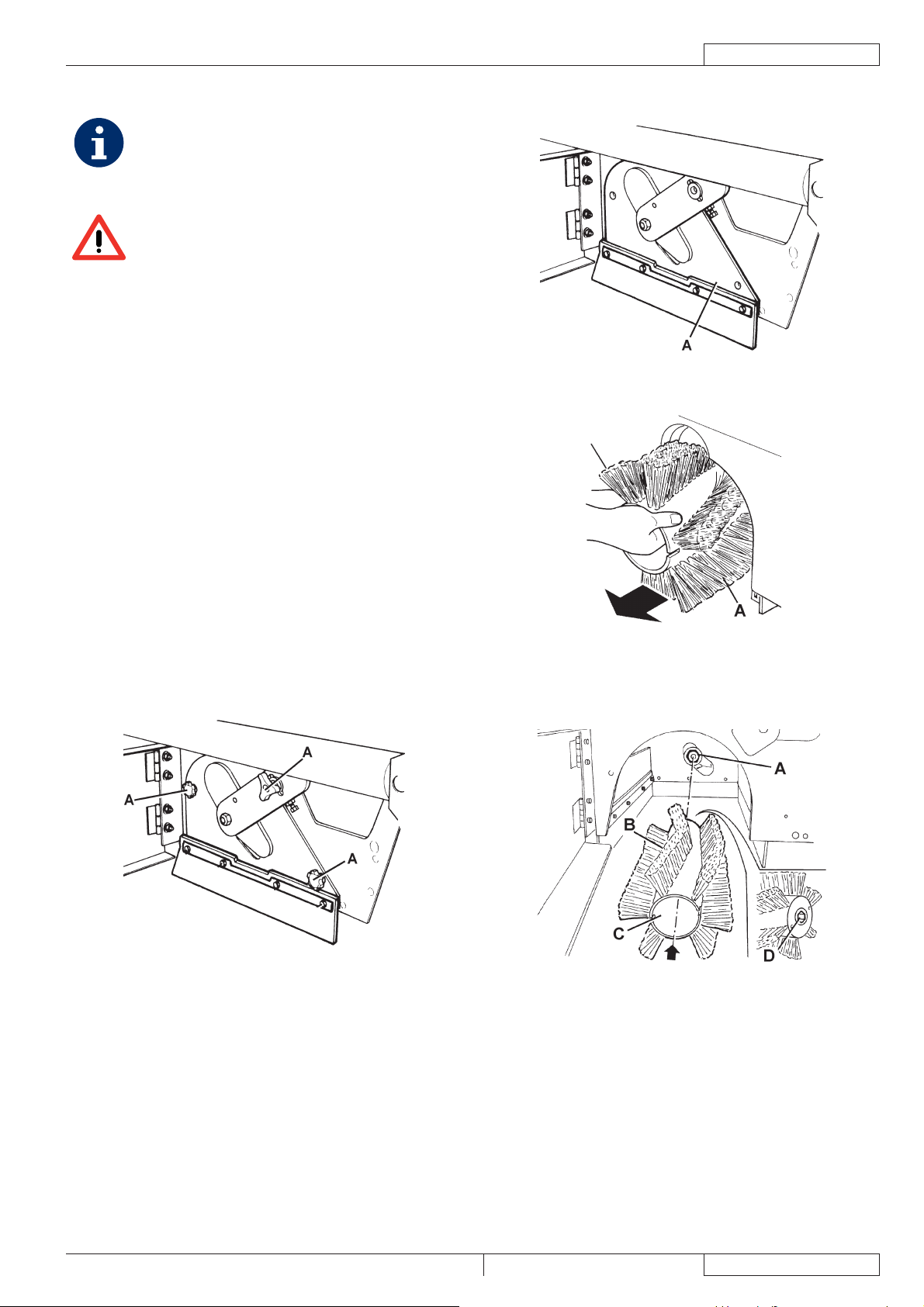
HAUPTKEHRWALZE AUSWECHSELN
HINWEIS
Es werden Hauptkehrwalzen und Seitenbesen
verschiedener Härtegrade geliefert. Diese
Arbeitsschritte sind bei allen Besen- und
Walzentypen anzuwenden.
ACHTUNG!
Es wird empfohlen, beim Auswechseln der
Hauptkehrwalze Arbeitshandschuhe zu tragen,
da Abfälle mit scharfen Kanten zwischen den
Borsten eingeklemmt sein könnten.
Das Gerät auf ebenem Untergrund abstellen und 1.
Feststellbremse mit dem Pedal (82) und dem Hebel (75)
betätigen.
Zündschlüssel (69) in Stellung 0 drehen und abziehen.2.
Haltevorrichtung (8) ausrasten und rechte Klappe (7) 3.
öffnen.
Knöpfe (A, Abb. 5) lösen und abnehmen.4.
Deckel des Hauptkehrwalzenraums (A, Abb. 6) abnehmen.5.
Hauptkehrwalze (A, Abb. 7) abnehmen.6.
Überprüfen, ob die Mitnehmernabe (A, Abb. 8) frei von 7.
Schmutz und Gegenständen (Stricke, Lappen usw.) ist, die
unbeabsichtigt aufgerollt wurden.
Beim Einbau der neuen Hauptkehrwalze die Borsten (B, 8.
Abb. 8) wie auf der Abbildung ausrichten.
Die neue Hauptkehrwalze (C, Abb. 8) in das Gerät 9.
einbauen. Sicherstellen, dass der Anschluss (D) an der
Hauptkehrwalze und die entsprechende Mitnehmernabe
(A) ineinander gesteckt sind.
Deckel des Hauptkehrwalzenraums (A, Abb. 6) anbringen 10.
und Knöpfe (A, Abb. 5) eindrehen.
Rechte Klappe (7) schließen und Haltevorrichtung (8) 11.
einrasten.
Hauptkehrwalzenhöhe wie im vorstehenden Abschnitt 12.
erläutert überprüfen und einstellen.
BETRIEBSANLEITUNG
Abbildung 6
Abbildung 7
DEUTSCH
P100219
P100220
Abbildung 5
P100218
Abbildung 8
SR 1301 P 1463388000(1)2008-05 A
P100221
21
Page 24
DEUTSCH
BETRIEBSANLEITUNG
SEITENBESENHÖHE ÜBERPRÜFEN UND
EINSTELLEN
HINWEIS
Es werden Hauptkehrwalzen und Seitenbesen
verschiedener Härtegrade geliefert. Diese
Arbeitsschritte sind bei allen Besen- und
Walzentypen anzuwenden.
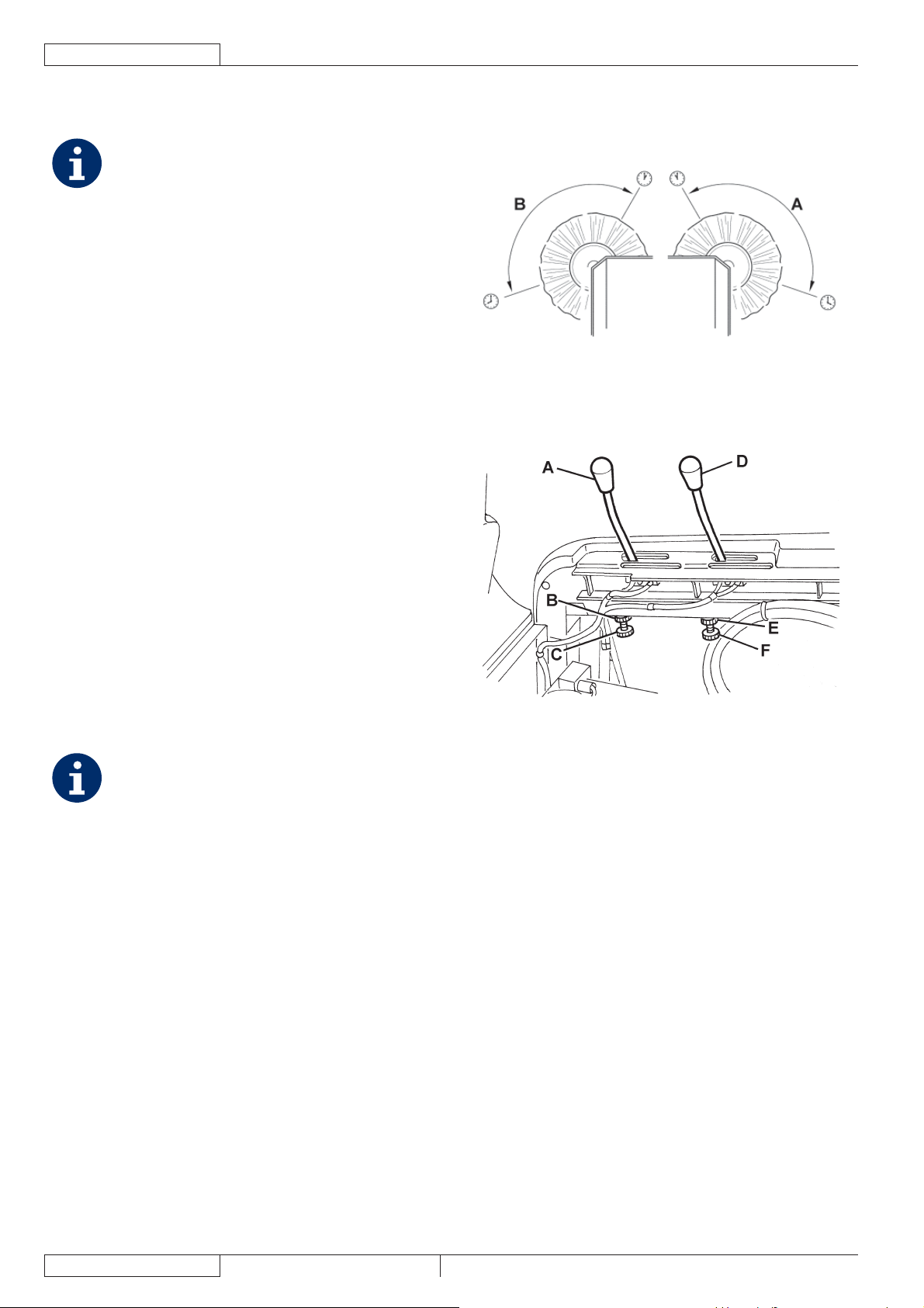
Bodenfreiheit der Seitenbesen wie folgt überprüfen:1.
Das Gerät auf ebenem Untergrund abstellen.•
Bei stehendem Gerät die Seitenbesen absenken und •
einige Sekunden drehen lassen.
Seitenbesen anhalten, anheben und Gerät zur Seite •
fahren.
Prüfen, ob die Seitenbesenspuren hinsichtlich •
Ausdehnung und Ausrichtung der Abbildung (A und B,
Abb. 9) entsprechen.
Weicht die Spur ab, die Höhe der Seitenbesen wie folgt
einstellen.
Feststellbremse mit dem Pedal (82) und dem Hebel (75) 2.
betätigen.
Zündschlüssel (69) in Stellung 0 drehen.3.
Haube (23) öffnen und mit der Stützstange (55) sichern.4.
Für den rechten Seitenbesen:5. Hebel (A, Abb. 10) durch
Lösen der Mutter (B) und Betätigen der Einstellvorrichtung
(C) bis zum Erhalt der richtigen (A, Abb. 9) Spur
verschieben. Einstellvorrichtung mit der Mutter (B, Abb. 10)
sichern.
Für den linken Seitenbesen: Hebel (D, Abb. 10) durch
Lösen der Mutter (E) und Betätigen der Einstellvorrichtung
(F) bis zum Erhalt der richtigen (A, Abb. 9) Spur
verschieben. Einstellvorrichtung mit der Mutter (E, Abb. 10)
sichern.
Nochmals die Arbeitsschritte unter Punkt 1 ausführen, 6.
um die korrekte Einstellung der Seitenbesenhöhe zu
überprüfen.
Ist die Einstellung wegen übermäßigen Verschleißes der 7.
Seitenbesen nicht mehr möglich, Seitenbesen wie im
nachstehenden Abschnitt erläutert austauschen.
HINWEIS
Falls erforderlich, kann auch die Neigung der
Seitenbesen eingestellt werden (siehe ServiceAnleitung).
P100222
Abbildung 9
P100223
Abbildung 10
22
1463388000(1)2008-05 A SR 1301 P
Page 25
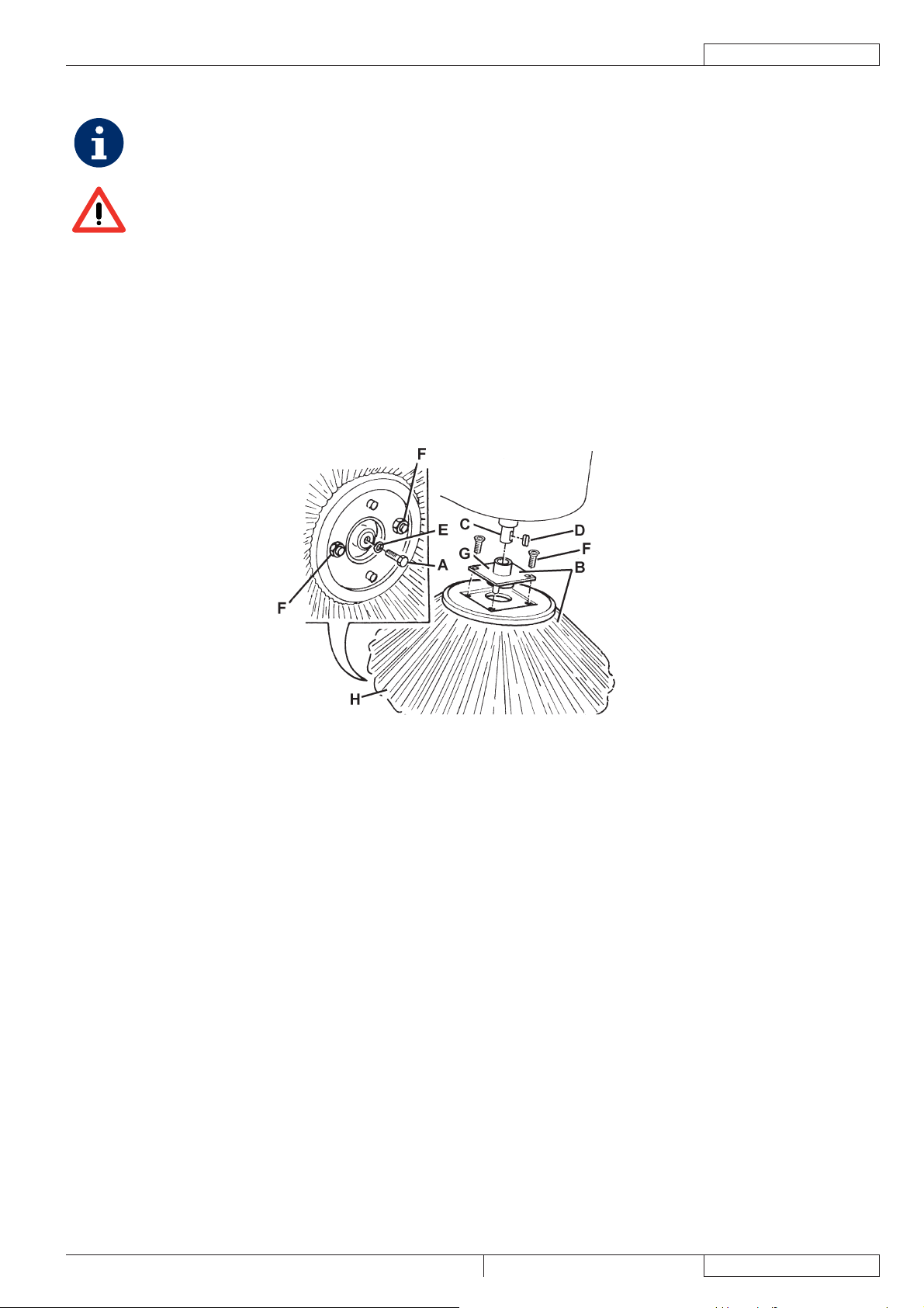
SEITENBESEN AUSWECHSELN
HINWEIS
Es werden Hauptkehrwalzen und Seitenbesen verschiedener Härtegrade geliefert. Diese Arbeitsschritte sind bei allen
Besen- und Walzentypen anzuwenden.
ACHTUNG!
Es wird empfohlen, beim Auswechseln der Seitenbesen Arbeitshandschuhe zu tragen, da Abfälle mit scharfen
Kanten zwischen den Borsten eingeklemmt sein könnten.
Das Gerät auf ebenem Untergrund abstellen und Feststellbremse mit dem Pedal (82) und dem Hebel (75) betätigen.1.
Zündschlüssel (69) in Stellung 0 drehen.2.
Betreffenden Seitenbesen mit dem Hebel (77) oder (78) anheben.3.
Schraube (A, Abb. 11) in der Mitte des Seitenbesens herausdrehen. Seitenbesen (B) von der Welle (C) lösen und zusammen 4.
mit der Nabe (B) abnehmen.
Keil (D) und Unterlegscheibe (E) zur Seite legen.
Die beiden Schrauben mit Muttern (F, Abb. 11) auf einer Werkbank entfernen und Nabe (G) vom Besen (H) abnehmen.5.
Den neuen Seitenbesen (H, Abb. 11) auf der Nabe (G) anbringen und die Schrauben mit Muttern (F) anziehen.6.
Keil (D) anbringen und den neuen Seitenbesen mit Nabe (B, Abb. 11) einbauen. Unterlegscheibe (E) anbringen und Schraube 7.
(A) eindrehen.
Seitenbesenhöhe wie im vorstehenden Abschnitt erläutert überprüfen und einstellen.8.
BETRIEBSANLEITUNG
DEUTSCH
Abbildung 11
P100224
SR 1301 P 1463388000(1)2008-05 A
23
Page 26
DEUTSCH
BETRIEBSANLEITUNG
FLACHFILTER (STAUBFILTER) REINIGEN UND AUF SCHÄDEN ÜBERPRÜFEN
HINWEIS
Neben den Standard-Papierfi ltern sind optional auch Polyesterfi lter erhältlich. Diese Arbeitsschritte sind bei allen
Filtertypen anzuwenden.
Das Gerät auf ebenem Untergrund abstellen und Feststellbremse mit dem Pedal (82) und dem Hebel (75) betätigen.1.
Zündschlüssel (69) in Stellung 0 drehen.2.
Haube (23) öffnen und mit der Stützstange (55) sichern.3.
Stecker des Ansauganlagenmotors (26) trennen.4.
Haltevorrichtungen (A, Abb. 12) ausrasten und Haube der Ansauganlage (B) abnehmen.5.
Stecker (A, Abb. 13) des Filterrüttlers trennen.6.
Knöpfe (B, Abb. 13) herausdrehen und Halterahmen (C) des Filters abnehmen.7.
Staubfi lter (D, Abb. 13) abnehmen.8.
Den Filter in geeigneter Umgebung unter freiem Himmel reinigen: Die der Gewebeseite (B, Abb. 14) gegenüberliegende Seite 9.
(A) auf eine ebene und saubere Oberfl äche klopfen.
Reinigung mit einem senkrechten Druckluftstrahl (C) mit maximal 6 bar abschließen: Druckluftstrahl im Abstand von
mindestens 30 cm ausschließlich auf die Gewebeseite (B) richten.
Filterkörper auf Risse prüfen.
Abhängig vom zu reinigenden Filtertyp ist Folgendes zu beachten:
Papierfi lter (Standard): Zur Vermeidung nicht reparabler Schäden nicht mit Wasser oder Reinigungsmittel säubern.•
Polyesterfi lter (optional): Der Filter kann zur gründlichen Reinigung mit Wasser und gegebenenfalls mit nicht •
schäumendem Reinigungsmittel gespült werden. Wird der Filter auf diese Weise gereinigt, verringert sich, selbst bei
hoher Filterqualität, die Lebensdauer des Filters, der folglich häufi ger ausgewechselt werden muss. Die Verwendung
ungeeigneter Reinigungsmittel beeinträchtigt die Funktionseigenschaften des Filters.
Falls erforderlich, die Gummidichtung (A, Abb. 15) im Filterfach vollständig reinigen und auf Schäden überprüfen. 10.
Gegebenenfalls austauschen.
Die Bauteile in umgekehrter Reiheinfolge einbauen und dabei insbesondere auf Folgendes achten:11.
Den Filter mit der Gewebeseite (B, Abb. 14) nach oben einbauen.•
A
AAB
P100225 P100226
Abbildung 12 Abbildung 13
24
P100227 P100228
Abbildung 14 Abbildung 15
1463388000(1)2008-05 A SR 1301 P
Page 27
TASCHENFILTER (STAUBFILTER) REINIGEN
UND AUF SCHÄDEN ÜBERPRÜFEN
HINWEIS
Die Taschenfi lter aus Polyesterfaser werden in der
Regel durch Betätigung des elektrischen Filterrüttlers
des Geräts sauber gehalten.
Falls als erforderlich erachtet, können die
ausgebauten Filter folgendermaßen gereinigt
werden.
Weisen die Filterfl ächen Schäden auf, ist der Filter
auszuwechseln.
Das Gerät auf ebenem Untergrund abstellen und 1.
Feststellbremse mit dem Pedal (82) und dem Hebel (75)
betätigen.
Zündschlüssel (69) in Stellung 0 drehen.2.
Haube (23) öffnen und mit der Stützstange (55) sichern.3.
Stecker des Ansauganlagenmotors (26) trennen.4.
Haltevorrichtungen (A, Abb. 12) ausrasten und Haube der 5.
Ansauganlage (B) abnehmen.
Knöpfe (A, Abb. 16) herausdrehen und Bügel (B) 6.
entfernen.
Stecker (A, Abb. 17) des Filterrüttlers trennen und 7.
Staubfi lter (A) entfernen.
Polyesterfi lterfl ächen in geeigneter Umgebung 8.
unter freiem Himmel wie folgt ausbauen. Die mit der
Reinigung beauftragte Person hat dabei eine geeignete
Schutzausrüstung (Handschuhe, Schutzmaske,
Schutzbrille) zu tragen.
Filterrüttlermotor (A, Abb. 18) durch Herausdrehen der 9.
beiden Befestigungsschrauben abnehmen.
Halterungseinheit des Filterrüttlermotors (B, Abb. 18) 10.
vollständig öffnen. Die Spannstangen (C) der Filtertaschen
werden gelöst.
Alle Spannstangen der Filtertaschen (D, Abb. 18) 11.
entfernen.
Zur Entfernung des oberen Rahmens (F, Abb. 18) obere 12.
Befestigungsschnur (E) lösen.
Abstandshalter (G, Abb. 18) der Filtertaschen abnehmen.13.
Die Polyesterfaserfl äche (H, Abb. 18) auf der schmutzigen 14.
Seite (mit einem Sauggerät) reinigen. Filter dabei ganz
ausbreiten oder jede Tasche einzeln reinigen. Gleichzeitig
beide Seiten des Taschenabstandshalters (G, Abb. 18)
absaugen und alle eventuell vorhandenen Ablagerungen
entfernen. Filteroberfl äche auf Risse überprüfen und
gegebenenfalls auswechseln. Zur Reinigung kann auch
ein Druckluftstrahl (maximal 6 bar) verwendet werden:
Druckluftstrahl auf die saubere Seite (in Richtung zur
schmutzigen Seite) richten.
ACHTUNG!
Es wird nicht empfohlen, den Filter mit Wasser
zu reinigen. Die Polyesterfaser könnte sich
zusammenziehen und unbrauchbar werden.
Falls erforderlich, die Gummidichtung (C, Abb. 17) 15.
vollständig reinigen und auf Schäden überprüfen.
Gegebenenfalls austauschen.
Die ausgebauten Bauteile in der umgekehrten Reihenfolge 16.
des Ausbaus wieder einbauen.
BETRIEBSANLEITUNG
Abbildung 16
Abbildung 17
F
D
B
DEUTSCH
P100229
P100230
E
G
H
C
A
Abbildung 18
SR 1301 P 1463388000(1)2008-05 A
P100231
25
Page 28
DEUTSCH
BETRIEBSANLEITUNG
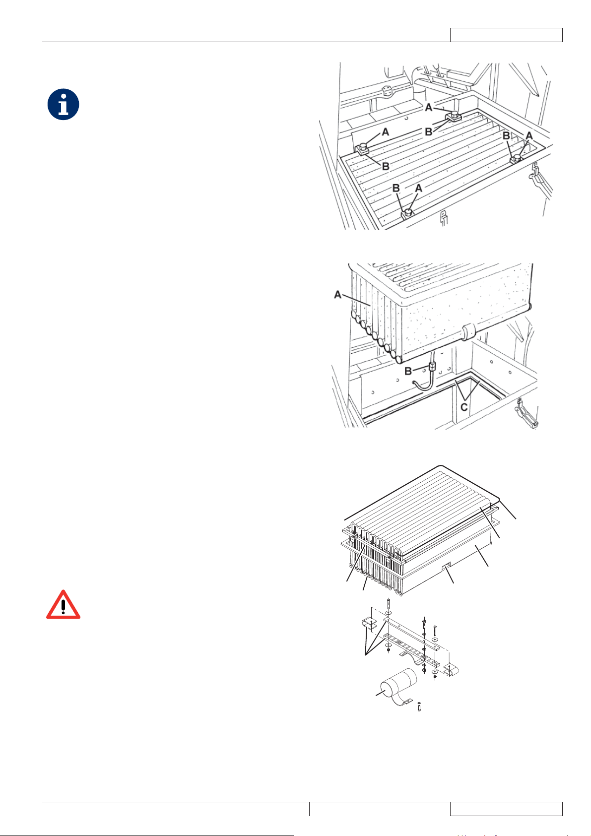
HÖHE UND FUNKTIONSFÄHIGKEIT DER SCHMUTZFANGKLAPPEN ÜBERPRÜFEN
Vorbereitung
Abfallbehälter (wie in der Betriebsanleitung erläutert) entleeren, um zu vermeinen, dass das Gewicht der Abfälle im Behälter 1.
die Überprüfung der Schmutzfangklappenhöhe beeinträchtigt.
Gerät auf einen ebenen Untergrund stellen, der als Bezugsfl äche für die Überprüfung der Schmutzfangklappenhöhe geeignet ist.2.
Feststellbremse mit dem Pedal (82) und dem Hebel (75) betätigen.3.
Zündschlüssel (69) in Stellung 0 drehen.4.
Seitliche Schmutzfangklappen überprüfen
Haltevorrichtungen (8) und (6) ausrasten und rechte (7) und linke (5) Klappe öffnen.5.
Seitliche Schmutzfangklappen (A, Abb. 19) auf Schäden überprüfen.6.
Weisen die Schmutzfangklappen Schnitte (A, Abb. 20) über 20 mm oder Brüche /Risse (B) über 10 mm auf,
Schmutzfangklappen auswechseln (für das Auswechseln der Schmutzfangklappen siehe Service-Anleitung).
Überprüfen, ob die Bodenfreiheit der seitlichen Schmutzfangklappen (A, Abb. 19) zwischen 0 und 3 mm beträgt (siehe Abb. 21).7.
Falls erforderlich, Schrauben (B, Abb. 19) lösen und Schmutzfangklappenstellung einstellen. Danach Schrauben (B) wieder
eindrehen.
Vordere und hintere Schmutzfangklappe überprüfen
Hauptkehrwalze wie im entsprechenden Abschnitt erläutert entfernen.8.
Vordere (A, Abb. 22) und hintere (B) Schmutzfangklappe auf Schäden überprüfen.9.
Weisen die Schmutzfangklappen Schnitte (A, Abb. 20) über 20 mm oder Brüche /Risse (B) über 10 mm auf,
Schmutzfangklappen auswechseln (für das Auswechseln der Schmutzfangklappen siehe Service-Anleitung).
Überprüfen, ob die vordere (A, Abb. 22) und die hintere (B) Schmutzfangklappe leicht auf dem Boden schleifen bzw. ob sie 10.
den Boden zumindest berühren (siehe Abb. 24).
Falls erforderlich, Schrauben (C, Abb. 22) lösen und Schmutzfangklappenstellung einstellen. Danach Schrauben (C) wieder
eindrehen.
Das Pedal für die vordere Schmutzfangklappe (81) ganz heruntertreten und überprüfen, ob sich die vordere 11.
Schmutzfangklappe um ca. 5 cm hebt.
Das Pedal loslassen und überprüfen, ob die Schmutzfangklappe in ihre Ausgangsstellung zurückkehrt und nicht in einer
Zwischenstellung stehenbleibt. Falls erforderlich, das Schmutzfangklappenkabel (A, Abb. 23) mit der Einstellvorrichtung (B)
vorne links auf der Schmutzfangklappe einstellen (für das Auswechseln des Steuerkabels der vorderen Schmutzfangklappe
siehe Service-Anleitung).
Montage
Die ausgebauten Bauteile in der umgekehrten Reihenfolge des Ausbaus wieder einbauen.12.
Abbildung 19 Abbildung 20 Abbildung 21
P100232 P100233 P100234
26
Abbildung 22 Abbildung 23 Abbildung 24
P100235 P100236 P100237
1463388000(1)2008-05 A SR 1301 P
Page 29
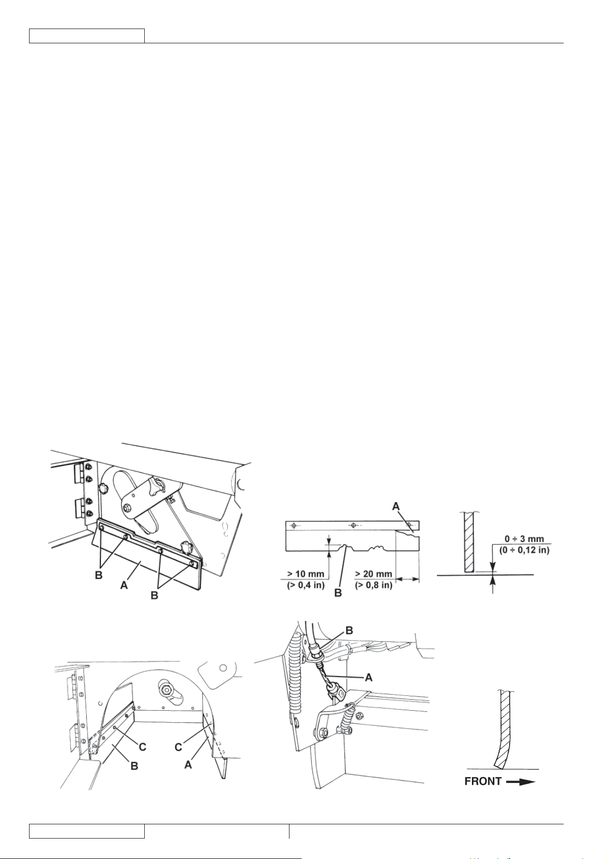
ÖLSTAND DER HYDRAULISCHEN HUBANLAGE
DES ABFALLBEHÄLTERS ÜBERPRÜFEN
ACHTUNG!
Die Überprüfung ist (wie auf der Abbildung)
bei vollständig abgesenktem Abfallbehälter (4)
durchzuführen.
Feststellbremse mit dem Pedal (82) und dem Hebel (75) 1.
betätigen.
Zündschlüssel (69) in Stellung 0 drehen.2.
Haube (23) öffnen und mit der Stützstange (55) sichern.3.
Überprüfen, ob der Ölstand im Tank (41) zwischen den 4.
Markierungen für Mindeststand (MIN) und Höchststand
(MAX) liegt (siehe Abb. 25).
Falls erforderlich, Ölstand durch die Einfüllöffnung (A, Abb. 5.
25) korrigieren. Das verwendete Öl muss die im Abschnitt
„Technische Daten“ angeführten Eigenschaften aufweisen.
Stützstange (55) abnehmen und Haube (23) schließen.6.
ÖLSTAND DER ANTRIEBSANLAGE
ÜBERPRÜFEN
Feststellbremse mit dem Pedal (82) und dem Hebel (75) 1.
betätigen.
Zündschlüssel (69) in Stellung 0 drehen.2.
Haube (23) öffnen und mit der Stützstange (55) sichern.3.
Überprüfen, ob der Ölstand im Tank (28) zwischen den 4.
Markierungen für Mindeststand (MIN) und Höchststand
(MAX) liegt (siehe Abb. 26).
Falls erforderlich, Ölstand mit Motoröl SAE 10W40 durch 5.
die Einfüllöffnung (A, Abb. 26) korrigieren.
Stützstange (55) abnehmen und Haube (23) schließen.6.
BETRIEBSANLEITUNG
Abbildung 25
MAX
MIN
DEUTSCH
P100238
A
Abbildung 26
P100239
SR 1301 P 1463388000(1)2008-05 A
27
Page 30
DEUTSCH
BETRIEBSANLEITUNG
MOTORÖLSTAND ÜBERPRÜFEN
Gerät auf ebenem Untergrund abstellen.1.
Feststellbremse mit dem Pedal (82) und dem Hebel (75) betätigen.2.
Zündschlüssel (69) in Stellung 0 drehen.3.
Haube (23) öffnen und mit der Stützstange (55) sichern.4.
Schrauben (45) herausdrehen, Haltevorrichtungen (46) ausrasten und Motorschutzabdeckung (44) abnehmen.5.
Deckel Motorölstand (34) abdrehen und mit einem sauberen Tuch reinigen. Deckel Motorölstand (34) bis zum Anschlag 6.
zudrehen und nach einigen Sekunden erneut abdrehen. Überprüfen, ob der Ölstand zwischen den Markierungen ADD
(Mindeststand) und FULL (Höchststand) (A, Abb. 27) liegt.
Liegt der Ölstand unter dem Mindeststand (ADD), Deckel des Motoröleinfüllstutzens (35) abnehmen und nachfüllen.
HINWEIS!
Mit demselben Öltyp nachfüllen, der sich auch im Motor befi ndet.
Deckel des Motoröleinfüllstutzens (35) anbringen und Ölstand wie vorstehend erläutert überprüfen.7.
Schritte 3 bis 5 in umgekehrte Reihenfolge durchführen.
MOTORÖLWECHSEL
HINWEIS!
Der Ölwechsel sollte bei noch warmem Motor durchgeführt werden, da das Öl dann leichter abfl ießt.
Gerät auf ebenem Untergrund abstellen.1.
Feststellbremse mit dem Pedal (82) und dem Hebel (75) betätigen.2.
Zündschlüssel (69) in Stellung 0 drehen.3.
Schrauben (48) herausdrehen, Haltevorrichtungen (49) ausrasten und linke Seitenschutzplatte (47) abnehmen.4.
Haube (23) öffnen und mit der Stützstange (55) sichern.5.
Schrauben (45) herausdrehen, Haltevorrichtungen (49) ausrasten und Motorschutzabdeckung (44) abnehmen.6.
Deckel des Motoröleinfüllstutzens (35) abnehmen.7.
Motorölablassschraube (38) vom Rohr (40) abnehmen und das gesamte Öl in einen geeigneten Behälter ablassen.8.
HINWEIS!
Das abgelassene Öl ist gemäß den gültigen Umwelthygienevorschriften entsorgen.
Motorölablassschraube (38) auf dem Rohr (40) anbringen.9.
Neues Öl durch die Öffnung des Einfüllstutzens (35) einfüllen.10.
HINWEIS
Für Motorölmenge und -typ siehe Kapitel „Technische Daten“ und Handbuch des Benzinmotors.
FULL
ADD
A
P100240
Abbildung 27
Deckel des Motoröleinfüllstutzens (35) anbringen.11.
Deckel Motorölstand (34) nach einigen Sekunden erneut abdrehen und überprüfen, ob der Ölstand zwischen den 12.
Markierungen ADD (Mindeststand) und FULL (Höchststand) (A, Abb. 27) liegt.
Falls erforderlich, nachfüllen. Deckel Motorölstand (34) zudrehen.
Schritte 4 bis 6 umgekehrte Reihenfolge durchführen.13.
28
1463388000(1)2008-05 A SR 1301 P
Page 31

BETRIEBSANLEITUNG
DEUTSCH
LUFTVORFILTER DES MOTORS REINIGEN UND EINSATZ DES MOTORLUFTFILTERS WARTEN
Gerät auf ebenem Untergrund abstellen.1.
Feststellbremse mit dem Pedal (82) und dem Hebel (75) betätigen.2.
Zündschlüssel (69) in Stellung 0 drehen.3.
Schrauben (48) herausdrehen, Haltevorrichtungen (49) ausrasten und linke Seitenschutzplatte (47) abnehmen.4.
Wie im Handbuch des Benzinmotors erläutert, Luftvorfi lter des Motors reinigen und/oder Einsatz des Motorluftfi lters warten (A, 5.
Abb. 28).
Linke Seitenschutzplatte (47) wieder montieren.6.
MOTORKÜHLSYSTEM REINIGEN
Gerät auf ebenem Untergrund abstellen.1.
Feststellbremse mit dem Pedal (82) und dem Hebel (75) betätigen.2.
Zündschlüssel (69) in Stellung 0 drehen.3.
Schrauben (48) herausdrehen, Haltevorrichtungen (49) ausrasten und linke Seitenschutzplatte (47) abnehmen.4.
Schrauben (B, Abb. 28) herausdrehen und Luftförderer (C) entfernen.5.
Motorkühlsystem (D) wie im Handbuch des Benzinmotors erläutert reinigen.6.
Linke Seitenschutzplatte (47) wieder montieren.7.
A
B
D
BC
P100241
Abbildung 28
SR 1301 P 1463388000(1)2008-05 A
29
Page 32

DEUTSCH
BETRIEBSANLEITUNG
FUNKENSCHUTZ REINIGEN
Gerät auf ebenem Untergrund abstellen.1.
Feststellbremse mit dem Pedal (82) und dem Hebel (75) betätigen.2.
Zündschlüssel (69) in Stellung 0 drehen.3.
Schrauben (48) herausdrehen, Haltevorrichtungen (49) ausrasten und linke Seitenschutzplatte (47) abnehmen.4.
Befestigungsschrauben herausdrehen und Abgasendrohr (53) abnehmen.5.
Funkenschutz wie im Handbuch des Benzinmotors erläutert reinigen.6.
Schritte 4 und 5 in umgekehrte Reihenfolge durchführen.7.
ZÜNDKERZE REINIGEN/AUSWECHSELN
Gerät auf ebenem Untergrund abstellen.1.
Feststellbremse mit dem Pedal (82) und dem Hebel (75) betätigen.2.
Zündschlüssel (69) in Stellung 0 drehen.3.
Haube (23) öffnen und mit der Stützstange (55) sichern.4.
Schrauben (45) herausdrehen, Haltevorrichtungen (46) ausrasten und Motorschutzabdeckung (44) abnehmen.5.
Zündkerze (51) wie im Handbuch des Benzinmotors erläutert reinigen/auswechseln.6.
Schritte 4 und 5 in umgekehrte Reihenfolge durchführen.7.
SICHERUNGEN ÜBERPRÜFEN/AUSTAUSCHEN/RÜCKSTELLEN
Gerät auf ebenem Untergrund abstellen und Feststellbremse mit dem Pedal (82) und dem Hebel (75) betätigen.1.
Zündschlüssel (69) in Stellung 0 drehen.2.
Haube (23) öffnen und mit der Stützstange (55) sichern.3.
Flachsicherungen überprüfen/austauschen
Abdeckung (A, Abb. 29) abnehmen und Position der auf dem Aufkleber angegebenen Sicherungen notieren.4.
Folgende Sicherungen (B) überprüfen/austauschen:5.
Sicherung F1 (30 A): Stromkreis Zündschlüssel•
Sicherung F2 (30 A): Filterrüttler•
Sicherung F3 (30 A): Ansauganlage•
Sicherung F4 (30 A): Hydraulikpumpe•
Sicherung F5 (10 A): Rundumkennleuchte (optional)•
Sicherung F6 (10 A): Arbeitsscheinwerfer (optional)•
Sicherung F7 (10 A): Stellantrieb Abfallbehälter•
Sicherung F8 (30 A): Reservesicherung•
Sicherung des Ladesystems überprüfen/austauschen
Sicherung des Ladesystems FD (70 A) (50) überprüfen/austauschen.6.
Selbstrückstellende Sicherungen überprüfen
Überprüfen, ob eine der folgenden Sicherungen möglicherweise ausgeschaltet ist und nach dem Abkühlen des 7.
entsprechenden Motors Sicherung rückstellen:
Sicherung FA (C, Abb. 29): Selbstrückstellende Sicherung Motor rechter Seitenbesen•
Sicherung FB (D): Selbstrückstellende Sicherung Motor linker Seitenbesen (optional)•
Sicherung FC (E): Selbstrückstellende Sicherung Hauptkehrwalzenmotor•
Einbau
Die ausgebauten Bauteile in der umgekehrten Reihenfolge des Ausbaus wieder einbauen.8.
A
E
C
D
B
30
P100249
Abbildung 29
1463388000(1)2008-05 A SR 1301 P
Page 33

BETRIEBSANLEITUNG
FEHLERSUCHE
Störung Mögliche Ursache Maßnahmen
Die Motorhaube (13) ist nicht richtig
geschlossen.
Der Motorölstand ist zu niedrig.
Der Motor springt trotz Verwendung des
Zündschlüssels nicht an.
Der Motor stoppt während des Kehrens.
Das Gerät nimmt nur geringe Mengen
Abfälle/Staub auf.
Trotz Betätigung des Fahrpedals fährt das
Gerät nicht oder nur langsam.
Der Abfallbehälter wird nicht angehoben.
Der Abfallbehälter wird nicht gekippt.
Der Abfallbehälter wird nicht abgesenkt.
Der Benzinmotor bleibt bei angehobener
Motorhaube (13) in Betrieb.
(*) Für die entsprechenden Anweisungen siehe Handbuch des Benzinmotors.
(**) Vom Nilfi sk-Kundendienst durchzuführen.
Der Kraftstoff ist verbraucht. Überprüfen, ob der Tank (30) Kraftstoff enthält.
Der Kraftstoff erreicht den Vergaser nicht.
Die Zündkerze erzeugt keinen Zündfunken.
Der Motorölstand ist zu niedrig.
Der Kraftstoff geht aus. Überprüfen, ob der Tank (30) Kraftstoff enthält.
Der Kraftstofffi lter ist verschmutzt. Kraftstofffi lter reinigen. (*)
Die Ansauganlage ist ausgeschaltet. Mit Schalter (56) Ansauganlage einschalten.
Der Staubfi lter ist verstopft. Staubfi lter reinigen.
Der Abfallbehälter ist voll. Abfallbehälter (4) entleeren.
Die Schmutzfangklappen sind beschädigt
oder falsch eingestellt.
Die Bodenfreiheit der Seitenbesen und/oder
Hauptkehrwalze ist nicht richtig eingestellt.
Die Feststellbremse ist betätigt.
Der Hydraulikölstand ist nicht korrekt. Hydraulikölstand im Tank (28) überprüfen.
Die Zentrifugalscheibe funktioniert nicht
richtig.
Das Fahrpedal ist falsch eingestellt. Fahrpedal einstellen. (**)
Der Hydraulikölstand ist nicht korrekt. Hydraulikölstand im Tank (41) überprüfen.
Die Sicherung F4 oder F7 ist unterbrochen. Sicherung ersetzen.
Die Sicherung F7 ist unterbrochen. Sicherung ersetzen.
Der Abfallbehälter ist nicht genügend
angehoben.
Der Abfallbehälter befi ndet sich nicht
vollständig in Horizontalstellung.
Nach bestimmten Wetterbedingungen läuft
das Öl der Hydraulikanlage verzögert durch
das Sicherheitsventil.
Sicherheitsmikroschalter der Motorhaube
funktioniert nicht.
DEUTSCH
Haube richtig schließen.
Überprüfen, ob der Motorölstand innerhalb der
Grenzwerte liegt (*).
Überprüfen, ob der Krafftstoff den Vergaser erreicht
und ob der Kraftstofffi lter sauber ist. (*)
Überprüfen, ob die Zündkerze einen Zündfunken
erzeugt. (*)
Überprüfen, ob der Motorölstand innerhalb der
Grenzwerte liegt (*).
Unversehrtheit und korrekte Einstellung der
Schmutzfangklappen (16, 17, 18, 19) überprüfen.
Höhe der Seitenbesen und/oder Hauptkehrwalze (10,
11, 12) einstellen.
Überprüfen, ob die Feststellbremse (84 mit 76) gelöst
ist.
Den korrekten Betrieb der Zentrifugalscheibe
(Kupplung Benzinmotor – Antriebsanlagenpumpe)
überprüfen. (**)
Abfallbehälter mehr als 300 mm anheben.
Abfallbehälter in Horizontalstellung bringen.
Kurz warten, bis das Hydrauliköl abfl ießt.
Mikroschalter reparieren. (**)
Für weitere Informationen setzen Sie sich bitte mit einem Nilfi sk-Kundendienst in Verbindung, bei dem die Service-Anleitung
erhältlich ist.
SR 1301 P 1463388000(1)2008-05 A
31
Page 34

DEUTSCH
BETRIEBSANLEITUNG
VERSCHROTTUNG
Die Geräteverschrottung hat bei einer autorisierten Verschrottungsstelle zu erfolgen.
Vor der Geräteverschrottung sind folgende Bauteile zu entfernen und zu trennen sowie gemäß Umwelthygienevorschriften
gesondert zu entsorgen:
Batterien –
Polyesterstaubfi lter –
Hauptkehrwalze und Seitenbesen –
Motoröl –
Hydrauliköl –
Ölfi lter Hydraulikanlage –
Kunststoffl eitungen und -teile –
Elektrische und elektronische Teile (*) –
(*) Wenden Sie sich insbesondere für die Verschrottung der elektrischen und elektronischen Teile an die örtliche Nilfi sk-
Niederlassung.
32
1463388000(1)2008-05 A SR 1301 P
Page 35

MANUEL D’UTILISATION
FRANÇAIS
TABLE DES MATIERES
INTRODUCTION .............................................................................................................................................................. 2
BUT ET CONTENU DU MANUEL ................................................................................................................................................... 2
DESTINATAIRES ............................................................................................................................................................................. 2
CONSERVATION DU MANUEL ....................................................................................................................................................... 2
DECLARATION DE CONFORMITE ................................................................................................................................................ 2
DONNEES D’IDENTIFICATION ...................................................................................................................................................... 2
AUTRES MANUELS DE REFERENCE ........................................................................................................................................... 2
PIECES DE RECHANGE ET ENTRETIEN ..................................................................................................................................... 2
MODIFICATIONS ET AMELIORATIONS ......................................................................................................................................... 3
CAPACITES OPERATIONNELLES ................................................................................................................................................. 3
CONVENTIONS .............................................................................................................................................................................. 3
DEBALLAGE / LIVRAISON ............................................................................................................................................. 3
SECURITE ....................................................................................................................................................................... 3
SYMBOLES UTILISES .................................................................................................................................................................... 3
INSTRUCTIONS GENERALES ....................................................................................................................................................... 4
DESCRIPTION DE LA MACHINE ................................................................................................................................... 6
STRUCTURE DE LA MACHINE ...................................................................................................................................................... 6
TABLEAU DE BORD ET COMMANDES ......................................................................................................................................... 8
ACCESSOIRES / OPTIONS ............................................................................................................................................................ 9
CARACTERISTIQUES TECHNIQUES ............................................................................................................................................ 9
SCHEMA ELECTRIQUE .................................................................................................................................................................11
SCHEMA HYDRAULIQUE DU SYSTEME DE SOULEVEMENT CONTENEUR DECHETS ........................................................ 13
SCHEMA HYDRAULIQUE DU SYSTEME DE TRACTION ........................................................................................................... 13
UTILISATION ................................................................................................................................................................. 14
AVANT LA MISE EN MARCHE DE LA MACHINE ......................................................................................................................... 14
MISE EN MARCHE ET ARRET DE LA MACHINE ........................................................................................................................ 14
MACHINE AU TRAVAIL ................................................................................................................................................................. 15
VIDANGE DU CONTENEUR DECHETS ...................................................................................................................................... 16
APRES L’UTILISATION DE LA MACHINE ....................................................................................................................................17
DEPLACEMENT PAR POUSSEE / REMORQUAGE DE LA MACHINE ....................................................................................... 17
REGLAGE DU FEU DE TRAVAIL (optionnel) ................................................................................................................................ 17
INACTIVITE PROLONGEE DE LA MACHINE .............................................................................................................................. 17
PREMIERE PERIODE D’UTILISATION ......................................................................................................................................... 17
ENTRETIEN ................................................................................................................................................................... 18
PLAN D’ENTRETIEN PROGRAMME ............................................................................................................................................ 18
CONTROLE ET REGLAGE DE LA HAUTEUR DU BALAI CENTRAL .......................................................................................... 20
REMPLACEMENT DU BALAI CENTRAL ...................................................................................................................................... 21
CONTROLE ET REGLAGE DE LA HAUTEUR DES BALAIS LATERAUX .................................................................................... 22
REMPLACEMENT DU BALAI LATERAL ....................................................................................................................................... 23
NETTOYAGE ET CONTROLE DE L’INTEGRITE DU FILTRE A POUSSIERE EN PANNEAU ..................................................... 24
NETTOYAGE ET CONTROLE DE L’INTEGRITE DU FILTRE A POCHES ................................................................................... 25
CONTROLE DE LA HAUTEUR ET DU FONCTIONNEMENT DES VOLETS ............................................................................... 26
CONTROLE DU NIVEAU D’HUILE DU SYSTEME HYDRAULIQUE DE SOULEVEMENT DU CONTENEUR DECHETS .......... 27
CONTROLE DU NIVEAU D’HUILE DU SYSTEME DE TRACTION .............................................................................................. 27
CONTROLE DU NIVEAU D’HUILE MOTEUR ............................................................................................................................... 28
REMPLACEMENT DE L’HUILE MOTEUR .................................................................................................................................... 28
NETTOYAGE DU PREFILTRE A AIR MOTEUR ET ENTRETIEN DE LA CARTOUCHE DU FILTRE A AIR MOTEUR ................ 29
NETTOYAGE DU CIRCUIT DE REFROIDISSEMENT DU MOTEUR ........................................................................................... 29
NETTOYAGE DU PARE-ETINCELLES ......................................................................................................................................... 30
NETTOYAGE / REMPLACEMENT DE LA BOUGIE D’ALLUMAGE .............................................................................................. 30
CONTROLE / REMPLACEMENT / RETABLISSEMENT DES FUSIBLES .................................................................................... 30
DEPISTAGE DES PANNES ........................................................................................................................................... 31
MISE A LA FERRAILLE ................................................................................................................................................. 32
SR 1301 P 1463388000(1)2008-05 A
1
Page 36

FRANÇAIS
MANUEL D’UTILISATION
INTRODUCTION
REMARQUE
Les nombres entre parenthèses se rapportent aux composants indiqués au chapitre Description de la machine.
BUT ET CONTENU DU MANUEL
Ce manuel se propose de fournir à l’opérateur toutes les informations nécessaires afi n qu’il puisse utiliser la machine correctement
et la gérer de la manière la plus autonome et sûre. Il comprend des informations relatives à l’aspect technique, la sécurité, le
fonctionnement, l’arrêt de la machine, l’entretien, les pièces de rechange et la mise à la ferraille.
Avant d’effectuer toute opération sur la machine, les opérateurs et les techniciens qualifi és doivent lire attentivement les instructions
contenues dans ce manuel. En cas de doutes sur la correcte interprétation des instructions, contacter Nilfi sk pour avoir plus de
renseignements.
DESTINATAIRES
Ce manuel s’adresse à l’opérateur aussi bien qu’aux techniciens préposés à l’entretien de la machine.
Les opérateurs ne doivent pas exécuter les opérations réservées aux techniciens qualifi és. Nilfi sk ne répond pas des dommages
dus à l’inobservance de cette interdiction.
CONSERVATION DU MANUEL
Le manuel d’utilisation doit être gardé près de la machine, dans une enveloppe spéciale et, surtout, loin de liquides et de tout ce qui
pourrait en compromettre l’état de lisibilité.
DECLARATION DE CONFORMITE
La Déclaration de Conformité est livrée avec la machine et en atteste la conformité aux lois en vigueur.
REMARQUE
La déclaration de conformité originelle est livrée en double exemplaire dans la documentation de la machine.
DONNEES D’IDENTIFICATION
Le numéro de série et le modèle de la machine sont indiqués sur la plaque (1).
L’année de fabrication de la machine est indiquée dans la Déclaration de Conformité, ainsi que par les deux premiers chiffres du
numéro de série de la machine.
Le numéro de série et le modèle du moteur à essence sont indiqués sur la plaque (33).
Ces informations sont nécessaires lors de la commande des pièces de rechange de la machine et du moteur à essence. Utiliser
l’espace suivant pour noter les données d’identifi cation de la machine et du moteur à essence.
Modèle de la MACHINE ....................................................................
Numéro de série de la MACHINE ......................................................
Modèle du MOTEUR .........................................................................
Numéro de série du MOTEUR ..........................................................
AUTRES MANUELS DE REFERENCE
Manuel du moteur à essence, livré avec la machine, qui constitue une partie intégrante de ce manuel. –
Les manuels suivants sont aussi disponibles : –
Catalogue de pièces de rechange (livré avec la machine)•
Manuel d’entretien (consultable auprès des Services après-vente Nilfi sk)•
PIECES DE RECHANGE ET ENTRETIEN
Pour toute nécessité concernant l’emploi, l’entretien et la réparation, s’adresser au personnel qualifi é ou directement aux Services
après-vente Nilfi sk. Utiliser toujours des pièces de rechange et des accessoires d’origine.
Pour l’assistance ou la commande de pièces de rechange et accessoires, contacter Nilfi sk en spécifi ant toujours le modèle et le
numéro de série de la machine.
2
1463388000(1)2008-05 A SR 1301 P
Page 37

MANUEL D’UTILISATION
FRANÇAIS
MODIFICATIONS ET AMELIORATIONS
Nilfi sk vise à un constant perfectionnement de ses produits et se réserve le droit d’effectuer des modifi cations et des améliorations
lorsqu’elle le considère nécessaire sans l’obligation de modifi er les machines précédemment vendues.
Il est entendu que toute modifi cation et / ou addition d’accessoires doit toujours être approuvée et réalisée par Nilfi sk.
CAPACITES OPERATIONNELLES
Cette balayeuse est conçue et fabriquée pour le nettoyage / balayage de sols lisses et solides et pour le ramassage de poussières
et déchets légers, en milieux civils et industriels, en condition de complète sécurité par un opérateur qualifi é.
CONVENTIONS
Toutes les références à en avant, en arrière, avant, arrière, droite ou gauche indiquées dans ce manuel doivent être considérées
comme référées à l’opérateur assis en position de conduite sur le siège (54).
DEBALLAGE / LIVRAISON
Pour déballer la machine, suivre attentivement les instructions sur l’emballage. –
Lors de la livraison de la machine, contrôler attentivement que l’emballage et la machine n’ont pas été endommagés pendant –
le transport. Si les dommages sont évidents, garder l’emballage de façon qu’il puisse être examiné par le transporteur qui l’a
livré. Contacter immédiatement le transporteur pour remplir une demande de dommages-intérêts.
Contrôler que le matériel livré avec la machine correspond à la liste suivante : –
Documentation technique :1.
Manuel d’utilisation de la balayeuse•
Manuel du moteur à essence•
Catalogue de pièces de rechange de la balayeuse•
N° 1 fusible de 10 A2.
N° 1 fusible de 70 A3.
SECURITE
On utilise la symbolique suivante pour signaler les conditions de danger potentielles. Lire attentivement ces informations et prendre
les précautions nécessaires pour protéger les personnes et les choses.
Pour éviter tout accident, la collaboration de l’opérateur est essentielle. Aucun programme de prévention des accidents du travail
ne peut résulter effi cace sans la totale collaboration de la personne directement responsable du fonctionnement de la machine. La
plupart des accidents qui peuvent survenir dans une entreprise, pendant le travail ou les déplacements, sont dus à l’inobservance
des plus simples règles de prudence. Un opérateur attentif et prudent est la meilleure garantie contre les accidents du travail et se
révèle indispensable pour compléter n’importe quel programme de prévention.
SYMBOLES UTILISES
DANGER !
Indique une situation dangereuse exposant l’opérateur au risque de blessures graves, voire mortelles.
ATTENTION !
Indique un risque potentiel d’accident pour les personnes ou de dommage matériel.
AVERTISSEMENT !
Indique un avertissement ou une remarque sur des fonctions clé ou utiles. Prêter la plus grande attention aux
segments de texte marqués par ce symbole.
REMARQUE
Indique une remarque sur des fonctions clé ou utiles.
CONSULTATION
Indique la nécessité de consulter le manuel d’utilisation avant d’effectuer toute opération.
SR 1301 P 1463388000(1)2008-05 A
3
Page 38
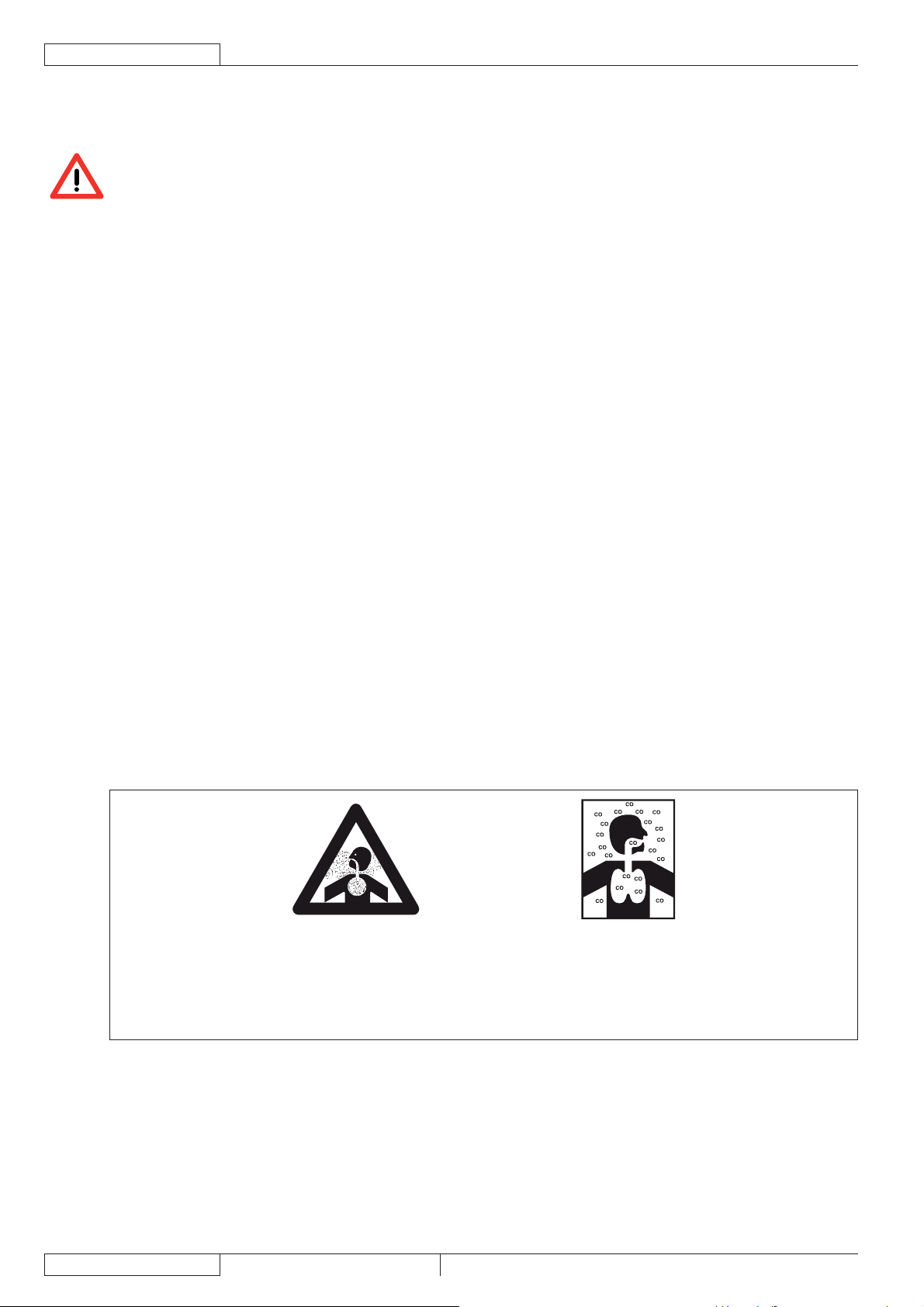
FRANÇAIS
MANUEL D’UTILISATION
INSTRUCTIONS GENERALES
Les avertissements et précautions spécifi ques suivants informent sur les potentiels risques de dommages à la machine ou aux
personnes.
DANGER !
Avant d’effectuer toute opération de nettoyage, d’entretien et de remplacement des composants, débrancher –
le connecteur de la batterie, enlever la clé de contact et actionner le frein de stationnement.
Cette machine doit être utilisée uniquement par le personnel adéquatement formé. L’utilisation de la machine –
est interdite aux enfants et aux personnes handicapées.
Ne pas porter de bijoux quand on travaille près des composants électriques. –
Tenir les étincelles, les fl ammes et les matériaux fumants et incandescents loin des batteries. Les batteries –
produisent des gaz potentiellement explosifs pendant l’utilisation ordinaire.
Ne pas travailler sous la machine soulevée, sans des supports fi xes de sécurité convenables. –
Chaque fois qu’on travaille sous le coffre ouvert, s’assurer que celui-ci ne peut pas se refermer –
accidentellement.
Ne pas opérer avec cette machine en présence de poudres, liquides ou vapeurs nuisibles, dangereux, –
infl ammables et / ou explosifs : la machine ne doit pas être utilisée pour ramasser des matériaux dangereux.
Attention : le carburant est extrêmement infl ammable. –
Ne pas fumer et ne pas utiliser des fl ammes libres près du lieu de ravitaillement ou de stockage du –
carburant.
Effectuer le ravitaillement de carburant à l’extérieur ou dans un endroit bien aéré et avec le moteur à l’arrêt. –
Arrêter le moteur et le laisser refroidir pendant quelques minutes avant de dévisser le bouchon du réservoir –
du carburant.
Afi n de permettre l’expansion du carburant, laisser une distance d’au moins 4 cm de l’ouverture de la –
goulotte de remplissage du réservoir.
Après avoir effectué le ravitaillement de carburant, contrôler que le bouchon du réservoir du carburant est
bien fermé.
Si, pendant le ravitaillement, du carburant est renversé, nettoyer soigneusement et permettre aux vapeurs de –
se dissiper avant de démarrer le moteur.
Eviter que le carburant entre en contacte avec la peau et d’en inhaler les vapeurs. Garder hors de la portée –
des enfants.
Ne pas incliner le moteur selon un angle excessif pour éviter toute sortie du carburant. –
Pendant le transport de la machine, le réservoir du carburant ne doit pas être plein et, dans tout cas, le –
robinet de carburant doit être fermé.
Ne pas poser d’objets sur le moteur. –
Arrêter le moteur avant d’effectuer toute opération. Pour éviter le démarrage accidentel du moteur, –
déconnecter le capuchon de la bougie d’allumage ou déconnecter la borne négative de la batterie.
Voir les NORMES DE SECURITE indiquées dans le manuel du moteur à essence, qui constitue une partie –
intégrante de ce manuel.
En cas d’installation à bord de batteries au plomb (WET), ne pas incliner la machine de plus de 30° depuis –
l’horizontale, car cela pourrait provoquer des pertes de liquide très corrosif. Au cas où il serait nécessaire
d’incliner la machine pour l’entretien, enlever les batteries.
ATTENTION !
Le monoxyde de carbone (CO) peut causer des dommages au cerveau et même la mort.
Le moteur à combustion interne de la machine émet du monoxyde de carbone.
Ne pas inhaler les gaz d’échappement.
Si l’on doit utiliser la machine dans un endroit fermé, s’assurer qu’il y ait une ventilation adéquate et des
assistants à vous aider.
4
1463388000(1)2008-05 A SR 1301 P
Page 39

MANUEL D’UTILISATION
ATTENTION !
Avant d’effectuer toute activité d’entretien / réparation, lire attentivement toutes les instructions qui –
concernent l’entretien / réparation.
Prendre les précautions convenables afi n que les cheveux, les bijoux, les parties non adhérentes des –
vêtements ne soient pas capturés par les parties en mouvement de la machine.
Pour éviter l’utilisation non autorisée de la machine, enlever la clé de contact. –
Avant de laisser la machine sans surveillance, veiller à ce que celle-ci ne puisse pas bouger de façon –
autonome.
Ne pas utiliser la machine sur des surfaces ayant une pente supérieure à la valeur indiquée sur la machine –
même.
Utilisez exclusivement les balais livrées avec la machine et spécifi ées dans le manuel d’utilisation. –
L’utilisation de balais différentes peut compromettre la sécurité.
Avant d’utiliser la machine, fermer tous les couvercles et / ou portillons. –
Ne pas utiliser la machine dans des endroits très poussiéreux. –
Ne pas laver la machine avec des jets d’eau directs ou sous pression ou avec des substances corrosives. –
Ne pas utiliser d’air comprimé pour le nettoyage général de la machine, sauf que pour les fi ltres (voir le –
paragraphe spécifi que).
Pendant l’utilisation de cette machine, faire attention à sauvegarder l’intégrité des autres personnes, en –
particulier des enfants.
Ne pas poser de conteneurs de liquides sur la machine. –
La température de stockage de la machine doit être comprise entre 0°C et +40°C. –
La température de travail de la machine doit être comprise entre 0°C et +40°C. –
L’humidité doit être comprise entre 30 % et 95 %. –
Protéger toujours la machine du soleil, de la pluie et d’autres intempéries, pendant le fonctionnement et en –
état d’arrêt. Garder la machine dans un endroit couvert et sec : elle a été conçue pour l’utilisation à sec, par
conséquent elle ne doit pas être utilisée ou gardée dehors, dans des conditions d’humidité.
Ne pas utiliser la machine comme moyen de transport ou de poussée / remorquage. –
La portée maximum de la machine, en plus du poids de l’opérateur, est de 110 kg (poids des déchets). –
Ne pas faire travailler les balais lorsque la machine est arrêtée pour ne pas endommager le sol. –
En cas d’incendie, il est préférable d’utiliser un extincteur à poudre, plutôt qu’un extincteur à eau. –
Ne pas heurter contre des étagères ou des échafaudages, en particulier en cas de danger de chute d’objets. –
Adapter la vitesse d’utilisation aux conditions d’adhérence. –
Ne pas utiliser la machine sur des rampes ou des inclinaisons ayant une pente supérieure aux valeurs –
spécifi ées.
La machine n’est pas approuvée pour l’utilisation sur les rues publiques. –
Ne pas altérer pour aucune raison les protections prévues pour la machine. –
Respecter scrupuleusement les instructions prévues pour l’entretien ordinaire. –
Ne pas enlever ou altérer les plaques installées sur la machine. –
S’assurer que les éventuelles anomalies de fonctionnement de la machine ne dépendent pas du manque –
d’entretien. Dans le cas contraire, demander l’intervention du personnel autorisé ou d’un Service après-vente
agréé.
En cas de remplacement de pièces, demander les pièces de rechange D’ORIGINE à un concessionnaire ou –
revendeur agréé.
Afi n de garantir la sécurité et le bon fonctionnement de la machine, faire effectuer l’entretien programmé –
prévu au chapitre spécifi que de ce manuel par du personnel autorisé ou par un Service après-vente agréé.
Lors de la mise à la ferraille, la machine ne doit pas être abandonnée par la présence de matériaux toxiques –
(batteries, huiles, matériaux plastiques, etc.), sujets à des lois qui prévoient l’élimination auprès de centres
spéciaux (voir le chapitre Mise à la ferraille).
Pendant le fonctionnement du moteur, le silencieux se chauffe ; ne pas toucher le silencieux lorsqu’il est –
chaud pour éviter des brûlures graves et des incendies.
Le fonctionnement du moteur avec une quantité d’huile insuffi sante peut endommager sérieusement le –
moteur même. Contrôler le niveau d’huile avec le moteur arrêté et la machine en position horizontale.
Ne pas faire fonctionner le moteur sans le fi ltre à l’air ; le moteur pourrait s’endommager. –
Les interventions d’assistance technique pour le moteur doivent être effectuées par un concessionnaire –
agréé.
Utiliser exclusivement des pièces de rechange d’origine ou des pièces équivalentes pour le moteur.
L’utilisation de pièces de rechange de qualité non équivalente peut sérieusement endommager le moteur.
Voir les NORMES DE SECURITE indiquées dans le manuel du moteur à essence, qui constitue une partie –
intégrante de ce manuel.
FRANÇAIS
SR 1301 P 1463388000(1)2008-05 A
5
Page 40

FRANÇAIS
MANUEL D’UTILISATION
DESCRIPTION DE LA MACHINE
STRUCTURE DE LA MACHINE
Plaque avec numéro de série / données techniques / 1.
marquage de conformité
Feu clignotant (toujours en fonction si la clé de contact est 2.
sur “I”) (optionnel)
Couvercle moteur système d’aspiration3.
Conteneur déchets (le vider lorsqu’il est plein)4.
Portillon gauche (ouvrir seulement pour les opérations 5.
d’entretien)
Dispositif de fermeture gauche avec vis de fi xation de 6.
sécurité
Portillon droit (pour enlever le balai central)7.
Dispositif de fermeture droit8.
Feu de travail (optionnel)9.
Balai latéral droit10.
Balai latéral gauche (optionnel)11.
Balai central12.
Coffre compartiment moteur13.
Roues arrière de traction sur essieu fi xe14.
Roue avant de direction15.
Volet latéral gauche16.
Volet latéral droit17.
Volet avant18.
Volet arrière19.
Conteneur fi ltre à poussière20.
Vis de réglage orientation feu de travail21.
Collecteur d’échappement moteur22.
Coffre compartiment moteur (ouvert)23.
Batterie24.
Boîte fusibles à lamelle25.
Connecteur moteur système d’aspiration26.
Pompe système de traction27.
Réservoir huile système de traction28.
Moteur à essence29.
Réservoir carburant30.
Bouchon de remplissage carburant31.
Filtre à air moteur32.
Modèle et numéro de série moteur à essence33.
Bouchon de niveau huile moteur34.
Bouchon goulotte de remplissage huile moteur35.
Dynamoteur36.
Vis de dégagement pompe hydraulique (pour le 37.
déplacement par poussée / remorquage de la machine si
le système de traction n’est pas disponible)
Bouchon de vidange huile moteur38.
Relais démarrage moteur39.
Tuyau de vidange huile moteur40.
Réservoir huile système hydraulique de soulèvement 41.
conteneur déchets
Relais d’activation pompe de soulèvement conteneur 42.
déchets
Moteurs système de traction43.
Protection moteur à essence44.
Vis de fi xation protection45.
Dispositifs de retenue protection46.
Panneau de protection latéral gauche
47.
Vis de fi xation panneau de protection48.
Dispositifs de retenue panneau de protection49.
Fusible système de chargement50.
Bougie d’allumage51.
Silencieux moteur52.
Terminal d’échappement moteur53.
Siège de conduite54.
Tige de support coffre55.
Diode56.
Schéma de branchement batteries57.
13254
10 9 15 11 18 6 16 5 14
21
3
20
9
1
4
19
14
12
17
8
7
P100206
6
1463388000(1)2008-05 A SR 1301 P
Page 41

STRUCTURE DE LA MACHINE (suite)
MANUEL D’UTILISATION
44
FRANÇAIS
39
56
50
27
37
31
43
45
41
30
33
26
42
22
46
25
28
35
52
53
43
57
24
12V
12V
36
55
34
51
29
38-40
48
47
49
32
23
P100207
SR 1301 P 1463388000(1)2008-05 A
7
Page 42

FRANÇAIS
MANUEL D’UTILISATION
TABLEAU DE BORD ET COMMANDES
Interrupteur de confi rmation soulèvement / abaissement et 61.
basculement conteneur déchets
Interrupteur avertisseur sonore62.
Emplacement pour interrupteur feu de travail (optionnel)63.
Poignée de réglage trace balai central64.
Tourner dans le sens contraire aux aiguilles d’une •
montre pour augmenter la trace du balai
Tourner dans le sens des aiguilles d’une montre pour •
réduire la trace du balai
Emplacement pour interrupteur optionnel65.
Interrupteur66.
(Appuyé sur la partie inférieure) activation système •
d’aspiration
(Appuyé sur la partie supérieure) activation secoueur•
Interrupteur de soulèvement / abaissement conteneur 67.
déchets
Interrupteur de basculement conteneur déchets68.
Clé de contact69.
Tournée en position “0”, elle arrête le moteur à essence •
et désactive toutes le fonctions de la machine.
Tournée en position “I”, elle active toutes le fonctions •
de la machine et le feu clignotant.
Tournée sur “Start” dans le sens des aiguilles d’une •
montre jusqu’à fi n de course, elle démarre le moteur à
essence ; dès que le moteur démarre, relâcher tout de
suite la clé, qui reviendra en position “I”.
Compteur horaire70.
Bouton-poussoir d’urgence. Il doit être appuyé en cas 71.
d’urgence pour arrêter toute fonction de la machine. Pour
le désactiver après l’utilisation, le tourner dans le sens de
la fl èche qui se trouve sur le bouton-poussoir même.
Volant72.
Poignée de réglage inclinaison volant73.
Dispositif de démarrage à froid moteur74.
Levier de blocage frein de stationnement. Elle bloque 75.
le frein de service (82) en le commutant en frein de
stationnement.
Pédale de marche avant / arrière76.
Levier de soulèvement / abaissement balai latéral droit77.
Levier de soulèvement / abaissement balai latéral gauche 78.
(optionnel)
Levier de réglage position longitudinale siège79.
Levier de soulèvement / abaissement balai central80.
Pédale volet avant81.
Pédale frein de service82.
82
81
73
72
74
75
64
76
80
79
69
70
61 62
77
71
63 65 66 67 68
78
P100208
8
1463388000(1)2008-05 A SR 1301 P
Page 43

MANUEL D’UTILISATION
FRANÇAIS
ACCESSOIRES / OPTIONS
Outre les composants présents dans le modèle standard, la machine peut être équipée des accessoires optionnels suivants, selon
l’emploi spécifi que de la machine :
Balai latéral gauche –
Balais central et latéraux avec poils plus ou moins durs par rapport au standard –
Filtre à poussière en polyester antistatique et en polyester BIA C –
Filtre à poches –
Feu clignotant –
Feu de travail –
Volet antitraces –
Roues antitraces –
Toit de protection –
Pour de plus amples informations relatives aux accessoires optionnels susmentionnés, s’adresser au revendeur agréé.
CARACTERISTIQUES TECHNIQUES
Caractéristiques générales Valeurs
Largeur de nettoyage (avec un balai latéral) 1.054 mm
Largeur de nettoyage (avec deux balais latéraux) 1.308 mm
Longueur machine 1.776 mm
Largeur machine (avec un balai latéral) 1.208 mm
Largeur machine (avec deux balais latéraux) 1.310 mm
Hauteur maximum machine (au volant) 1.350 mm
Hauteur minimum du sol (volets non compris) 60 mm
Hauteur maximum de soulèvement conteneur déchets 1.650 mm
Hauteur minimum / maximum de vidange déchets du sol 270 / 1.370 mm
Rayon de braquage minimum 1.685 mm
Dimensions balai central (diamètre x longueur) 300 x 800 mm
Diamètre balai latéral 500 mm
Vitesse maximum en marche avant 7 km/h
Vitesse maximum en marche arrière 3 km/h
Pente maximum franchissable 20%
Capacité conteneur déchets 130 Litres
Poids maximum soulevable par le conteneur déchets 110 kg
Poids essieu avant en ordre de marche 297 kg
Poids essieu arrière en ordre de marche 446 kg
Poids total machine en ordre de marche (avec opérateur à bord) 743 kg
Pression spécifi que au sol roues arrière 1,2 N/mm
Pression spécifi que au sol roues avant 1,1 N/mm
Roue avant de direction (diamètre x largeur) 305 x 92 mm
Roues arrière de traction (diamètre x largeur) 305 x 92 mm
Niveau pression acoustique à l’oreille de l’opérateur (ISO 11201, ISO 4871) (LpA) 80 dB(A) ± 3 dB(A)
Puissance acoustique émise par la machine (ISO 3744, ISO 4871) (LwA) 98 dB (A)
Niveau de vibrations au bras de l’opérateur (ISO 5349-1) (*) < 2,5 m/s
Niveau de vibrations transmises au corps de l’opérateur (ISO 2631-1) (*) < 0,5 m/s
(*) En conditions de travail normales, sur une surface horizontale d’asphalte.
2
2
2
2
Moteur à essence (*) Données
Marque Briggs & Stratton
Modèle Vanguard 9 HP
Puissance réglée (ISO 1585) 6,7 kW
Régime de travail 3.100 ± 50 tr/mn
Consommation moyenne 1,7 litres / heure
Capacité réservoir carburant 8,5 Litres
Type d’huile utilisée SAE 5 W 30 - SYNTHETIQUE API SJ
(*) Pour les autres données / valeurs du moteur à essence, voir le Manuel spécifi que.
SR 1301 P 1463388000(1)2008-05 A
9
Page 44

FRANÇAIS
MANUEL D’UTILISATION
Aspiration et fi ltrage poussières Valeurs
Filtre à poussière en papier de 15-20 m 3,6 m
2
Dépression logement balai central 10,9 mm/H2O
Système électrique Valeurs
Batteries 2 x 12 V – 70 Ah
Moteur système d’aspiration 310 W, 3.000 tr/mn
Moteur balai central 500 W, 550 tr/mn
Moteur secoueur 90 W, 5.700 tr/mn
Moteur secoueur pour fi ltre à poches (optionnel) 110 W, 3.000 tr/mn
Système hydraulique de traction Valeurs
Pompe système de traction SAUER HIDRO-GEAR BDP 10A
Cylindrée pompe système de traction 10,2 cm
Cylindrée pompe de remplissage 1,9 cm
3
3
Pression maximum de travail 70 Bars
Pression maximum de pointe 145 Bars
Capacité réservoir huile système hydraulique 0,8 Litres
Capacité totale circuit hydraulique 1,2 Litres
Type d’huile utilisée SAE 10 W 40
Système hydraulique de soulèvement conteneur déchets Valeurs
Pompe Parker 108 AE S32 – 24 V
Pression maximum 110 Bars
Capacité réservoir huile 0,75 Litres
Capacité totale circuit hydraulique 1,4 Litres
Huile système hydraulique (température ambiante supérieure à 10°C) AGIP Arnica 46 (*)
AVERTISSEMENT !
En cas d’emploi de la machine avec températures inférieures à +10°C, on conseille de remplacer l’huile avec
une huile équivalente à viscosité 32 cSt. En cas de températures inférieures à 0°C, utiliser une huile à viscosité
encore inférieure.
(*) Voir la table des caractéristiques de l’huile et la table des spécifi cations de référence ci-dessous.
CARACTERISTIQUES TECHNIQUES SPECIFICATIONS DE REFERENCE
AGIP ARNICA 46 32 ISO-L-HV
Viscosité à 40°C mm
Viscosité à 100°C mm
Coeffi cient de viscosité / 150 157 AISE 127
Point d’éclair COC °C 215 202 ATOS Tab. P 002-0/I
Point d’écoulement °C -36 -36 BS 4231 HSE
Masse volumique à 15°C kg/l 0,87 0,865 CETOP RP 91 H HV
2
/s 45 32 ISO 11158
2
/s 7,97 6,40 AFNOR NF E 48603 HV
COMMERCIAL HYDRAULICS
Danieli Standard 0.000.001 (AGIP ARNICA 22, 46, 68)
EATON VICKERS I-286-S3
EATON VICKERS M-2950
DIN 51524 t.3 HVLP
LAMB LANDIS-CINCINNATI P68, P69, P70
LINDE
PARKER HANNIFIN (DENISON) HF-0
REXROTH RE 90220-1/11.02
SAUER-DANFOSS 520L0463
10
1463388000(1)2008-05 A SR 1301 P
Page 45

SCHEMA ELECTRIQUE
Légende
BAT Batterie 24 V
BE1 Feu tournant (optionnel)
BLK Cadre moteur à essence
BZ1 Avertisseur sonore de marche arrière - Avertisseur sonore
C1 Condensateur avertisseur sonore de marche arrière
EBD Carte diode
ES0 Relais moteur en marche
ES1 Relais pompe soulèvement conteneur déchets
ES2 Relais pompe abaissement conteneur déchets
ES3 Relais secoueur
ES4 Relais système d’aspiration
ES5 Télérupteur mise en marche
ES6 Télérupteur balai central
FA Fusible restaurable balai latéral droit (10 A)
FB Fusible restaurable balai latéral gauche (10 A) (optionnel)
FC Fusible restaurable balai central (30 A)
FD Fusible système de chargement (70 A)
F1 Fusible clé (30 A)
F2 Fusible secoueur (30 A)
F3 Fusible système d’aspiration (30 A)
F4 Fusible pompe soulèvement conteneur déchets (30 A)
Fusible avertisseur sonore de marche arrière et feu tournant
F5
(10 A)
F6 Fusible feu de travail (10 A)
F7 Fusible actionneur basculement conteneur déchets (10 A)
HM Compteur horaire
K1 Clé de contact
L1 Feu de travail (optionnel)
M1 Pompe de soulèvement conteneur déchets
M2 Actionneur basculement conteneur déchets
M3 Moteur secoueur
M4 Moteur système d’aspiration
M5 Moteur balai latéral droit
M6 Moteur balai latéral gauche (optionnel)
M7 Moteur balai central
M8 Dynamo
P1 Interrupteur avertisseur sonore
SPK Bougie moteur à essence
SW1 Interrupteur système d’aspiration / secoueur
SW2 Microinterrupteur balai latéral droit
SW3 Interrupteur de soulèvement / abaissement conteneur déchets
SW4 Interrupteur de basculement conteneur déchets
SW5 Interrupteur de confi rmation mouvement conteneur déchets
SW6 Microinterrupteur conteneur déchets en position horizontale
SW7 Microinterrupteur fi n de course conteneur déchets fermé
SW8 Microinterrupteur conteneur déchets soulevé
SW9 Microinterrupteur fi n de course conteneur déchets ouvert
SW10 Microinterrupteur marche arrière
SW11 Microinterrupteur coffre ouvert
SW12 Interrupteur feu de travail (optionnel)
SW13 Microinterrupteur balai latéral gauche (optionnel)
SW14 Microinterrupteur balai central
SWS Bouton-poussoir d’urgence
MANUEL D’UTILISATION
Codes des couleurs
BK Noir
BU Bleu clair
BN Marron
GN Vert
GY Gris
OG Orange
PK Rose
RD Rouge
VT Violet
WH Blanc
YE Jaune
FRANÇAIS
SR 1301 P 1463388000(1)2008-05 A
11
Page 46

FRANÇAIS
MANUEL D’UTILISATION
SCHEMA ELECTRIQUE (suite)
12
P100209
1463388000(1)2008-05 A SR 1301 P
Page 47

MANUEL D’UTILISATION
SCHEMA HYDRAULIQUE DU SYSTEME DE SOULEVEMENT CONTENEUR DECHETS
Légende
Réservoir huile1.
Filtre à huile2.
Pompe3.
Moteur4.
Soupape d’arrêt cylindre de soulèvement5.
Cylindre de soulèvement conteneur déchets6.
6
5
FRANÇAIS
200 BAR
110 BAR
750cc / HYDRAULIC OIL 32 cSt
2
1
SCHEMA HYDRAULIQUE DU SYSTEME DE TRACTION
Légende
Réservoir huile1.
Filtre à huile2.
Pompe3.
Moteurs4.
200 BAR
3
70 BAR
4
P100210
4
3000
RPM
100
MICRON
10,2 CC/REV.
2
AB
88 CC/REV.
A
88 CC/REV.
3
A
B
4
B
1
SR 1301 P 1463388000(1)2008-05 A
P100211
13
Page 48

FRANÇAIS
UTILISATION
MANUEL D’UTILISATION
72
54
79
69
71
80
73
82
81
31
78
75
66
74
77
10 11
18
76
12
ATTENTION !
Des plaques adhésives appliquées sur certains points de la machine indiquent :
DANGER –
ATTENTION –
AVERTISSEMENT –
CONSULTATION –
Lors de la lecture de ce manuel, l’opérateur doit bien comprendre le sens des symboles illustrés sur les plaques.
Ne pas couvrir les plaques et les remplacer immédiatement en cas d’endommagement.
P100212
AVANT LA MISE EN MARCHE DE LA MACHINE
Si besoin est, dévisser le bouchon (31) et effectuer le ravitaillement de carburant.1.
ATTENTION !
Afi n de permettre l’expansion du carburant, laisser une distance d’au moins 4 cm de l’ouverture de la goulotte
de remplissage du réservoir.
Contrôler que la machine n’a pas de portillons / coffres ouverts et qu’elle se trouve dans des conditions normales d’utilisation.2.
Si la machine n’a pas encore été utilisée après le transport, vérifi er que tous les sabots et les moyens de blocage utilisés pour 3.
le transport ont été enlevés.
MISE EN MARCHE ET ARRET DE LA MACHINE
Mise en marche de la machine
S’asseoir en position de conduite sur le siège (54) et régler la position du siège selon son propre confort à l’aide du levier (79).1.
Tirer la poignée (73) pour la débloquer, puis régler l’inclinaison du volant (72) selon son propre confort. Après le réglage, 2.
relâcher la poignée (73) et bouger légèrement le volant pour faciliter l’engagement du dispositif de retenue intérieur.
Activer le frein de stationnement au moyen de la pédale (82) et du levier (75).3.
Soulever le balai central et les balais latéraux à l’aide des leviers correspondants (80), (77), (78).4.
Tirer le dispositif de démarrage à froid (74) du moteur.5.
REMARQUE
Ne pas utiliser le dispositif de démarrage à froid si le moteur est chaud et si la température de l’air est suffi samment
élevée.
Démarrer le moteur à essence au moyen de la clé de contact (69). Dès que le moteur démarre, relâcher tout de suite la clé de 6.
contact.
ATTENTION !
Pendant le démarrage du moteur au moyen de la clé de contact (69) ne pas appuyer sur la pédale de marche
(76).
14
1463388000(1)2008-05 A SR 1301 P
Page 49

MANUEL D’UTILISATION
Après le démarrage, laisser tourner le moteur pendant quelques secondes, puis relâcher le dispositif de démarrage à froid 7.
(74).
Laisser chauffer le moteur pendant quelques minutes.8.
Désactiver le frein de stationnement en appuyant sur la pédale (82) et en débloquant en même temps le levier (75).9.
Se porter sur le lieu de travail, démarrer la machine les mains sur le volant (72) et appuyer sur la partie avant de la pédale (76) 10.
pour la marche avant et sur la partie arrière pour la marche arrière.
La vitesse d’avance est réglable de zéro à la valeur maximum, selon la pression exercée sur la pédale.
Baisser le balai central à l’aide du levier (80), puis activer le système d’aspiration en appuyant sur la partie inférieure de 11.
l’interrupteur (66).
Baisser le balai latéral droit au moyen du levier (77).12.
Baisser le balai latéral gauche, si équipé, au moyen du levier (78).13.
REMARQUE
Tous les balais (10, 11, 12) peuvent être baissés et soulevés même avec la machine en mouvement.
Les balais ne tournent pas s’ils sont soulevés.
Commencer le travail de balayage en manœuvrant le volant (72) et en appuyant sur la pédale (76) pour faire avancer la 14.
machine.
FRANÇAIS
Arrêt de la machine
Pour arrêter la machine, relâcher la pédale (76).15.
Pour arrêter la machine rapidement, appuyer aussi sur la pédale du frein de service (82).
Pour arrêter la machine immédiatement en cas d’urgence, appuyer sur le bouton-poussoir d’urgence (71).
Pour désactiver le bouton-poussoir d’urgence (71) après son activation, le tourner dans le sens de la fl èche qui se trouve sur
le bouton-poussoir même.
Soulever le balai central et les balais latéraux à l’aide des leviers correspondants (80), (77), (78).16.
Désactiver le système d’aspiration au moyen de l’interrupteur (66).17.
Arrêter la machine en tournant la clé de contact (69) sur “0”, puis l’enlever.18.
Activer le frein de stationnement en appuyant sur la pédale (82) et en actionnant en même temps le levier de blocage (75) du 19.
frein.
MACHINE AU TRAVAIL
Ne pas s’arrêter pendant longtemps dans la même position avec les balais qui tournent : des traces non désirées pourraient 1.
rester sur le sol.
Pour collecter les déchets légers et volumineux, soulever le volet avant (18) en appuyant sur la pédale (81) ; considérer que 2.
pendant que le volet avant est soulevé, la capacité d’aspiration de la machine est réduite.
ATTENTION !
S’il est nécessaire d’opérer sur un sol mouillé, il faut désactiver le système d’aspiration au moyen de
l’interrupteur (66) pour protéger le fi ltre à poussière.
Pour un bon travail de balayage il faut que le fi ltre poussières soit le plus propre possible. Pour le nettoyer pendant le cycle 3.
de travail, activer le secoueur pour peu de temps en appuyant sur la partie supérieure de l’interrupteur (66), puis activer à
nouveau le système d’aspiration en appuyant sur la partie inférieure de l’interrupteur (66).
Répéter l’opération en moyenne toutes les 10 minutes pendant le travail (selon la quantité de poussière du milieu à nettoyer).
REMARQUE
Cette opération peut être effectuée même avec la machine en mouvement.
AVERTISSEMENT !
Lorsque le fi ltre à poussière est obstrué et / ou le conteneur déchets est plein, la machine n’arrive plus à
collecter ni de poussière ni de déchets.
Vider le conteneur déchets (4) chaque fois qu’il est plein ainsi qu’à la fi n du travail (voir la procédure au paragraphe suivant).4.
AVERTISSEMENT !
Le moteur à essence est équipé d’un système d’alarme afi n d’éviter tout dommage au moteur en cas de quantité
d’huile insuffi sante dans le carter. Le système d’alarme arrête automatiquement le moteur avant que le niveau
d’huile moteur dans le carter soit descendu au-dessous de la limite de sécurité.
SR 1301 P 1463388000(1)2008-05 A
15
Page 50

FRANÇAIS
MANUEL D’UTILISATION
VIDANGE DU CONTENEUR DECHETS
ATTENTION !
Vider toujours le conteneur déchets avec le moteur en marche.
Pour éviter que la batterie ne se décharge, ne pas vider le conteneur déchets avec le moteur à l’arrêt.
La hauteur maximum de déchargement du conteneur déchets est de 1.370 mm (voir Fig. 2).1.
Pour effectuer la vidange, se porter à proximité du bac de collecte des déchets et procéder comme suit :2.
Soulever les balais latéraux et central.•
Désactiver le système d’aspiration au moyen de l’interrupteur (66).•
Activer le secoueur en appuyant sur la partie supérieure de l’interrupteur (66).•
ATTENTION !
Opérer toujours sur un sol plat afi n d’éviter que la machine se déséquilibre.
68
82
81
4
75
61
67
66
P100213
ATTENTION !
Pendant le soulèvement et la vidange du conteneur déchets (4), maintenir le frein de stationnement activé à
l’aide de la pédale (82) et du levier (75).
Tenir les personnes à distance de la machine, en particulier de l’endroit du conteneur déchets (4).3.
Appuyer en même temps sur l’interrupteur de confi rmation (61) et sur l’interrupteur de soulèvement (67), en soulevant le 4.
conteneur déchets (A, Fig. 1) à la hauteur désirée.
Appuyer en même temps sur l’interrupteur de confi rmation (61) et sur l’interrupteur de basculement (68) du conteneur déchets 5.
(B, Fig. 2) et décharger les déchets dans le bac de collecte (A).
AVERTISSEMENT !
Le basculement du conteneur déchets (B, Fig. 2) n’est possible qu’après avoir soulevé le conteneur à une
hauteur minimum de 270 mm.
Appuyer en même temps sur l’interrupteur de confi rmation (61) et sur l’interrupteur de basculement (68) du conteneur déchets 6.
pour qu’il revienne à la position horizontale.
Appuyer en même temps sur l’interrupteur de confi rmation (61) et sur l’interrupteur d’abaissement (67) du conteneur déchets 7.
pour le baisser complètement.
AVERTISSEMENT !
Le conteneur déchets peut être baissé seulement s’il se trouve dans sa position horizontale.
La machine est prête pour reprendre le travail de balayage.8.
A
B
A
16
P max
110 Kg
(242,5 lb)
1370 mm (54 in)
P100214 P100215
Figure 1 Figure 2
1463388000(1)2008-05 A SR 1301 P
Page 51

MANUEL D’UTILISATION
FRANÇAIS
APRES L’UTILISATION DE LA MACHINE
Le travail effectué, avant de laisser la machine :
Activer le secoueur pour peu de temps en appuyant sur la partie supérieure de l’interrupteur (66). –
Vider le conteneur déchets (4) (voir la procédure au paragraphe précédent). –
Soulever le balai central à l’aide du levier (80). –
Soulever les balais latéraux au moyen des leviers (77) et (78). –
Arrêter la machine en tournant la clé de contact (69) sur “0”, puis l’enlever. –
Activer le frein de stationnement en appuyant sur la pédale (82) et en actionnant en même temps le levier de blocage (75) du –
frein.
DEPLACEMENT PAR POUSSEE / REMORQUAGE DE LA MACHINE
Pour déplacer aisément la machine arrêtée par poussée / remorquage, il est nécessaire de procéder comme suit :
Arrêter la machine en tournant la clé de contact (69) sur “0”. –
Ouvrir le coffre (23) et le bloquer au moyen de la tige de support (55). –
Enlever la vis (37). –
Enlever la tige de support (55) et fermer le coffre (23). –
Déplacer la machine par poussée / remorquage. –
Après avoir déplacé la machine par poussée / remorquage, installer la vis (37). –
REGLAGE DU FEU DE TRAVAIL (optionnel)
Pour le réglage éventuel de l’orientation du faisceau lumineux du feu de travail (9), agir sur les vis (21).
INACTIVITE PROLONGEE DE LA MACHINE
Si l’on prévoit de ne pas utiliser la machine pendant plus de 30 jours, il est convenable d’effectuer les opérations suivantes :
S’assurer de garder la machine dans un endroit sec et propre.1.
Débrancher le connecteur négatif (–) des batteries (24).2.
Utiliser le moteur à essence (29) comme décrit dans le manuel spécifi que.3.
PREMIERE PERIODE D’UTILISATION
Après la première période d’utilisation (les 5 premières heures), il faut :
Contrôler le serrage des dispositifs de fi xation et de connexion ; vérifi er que les parties visibles sont intactes et sans pertes.1.
Remplacer l’huile du moteur à essence (voir le chapitre Entretien).2.
SR 1301 P 1463388000(1)2008-05 A
17
Page 52

FRANÇAIS
MANUEL D’UTILISATION
ENTRETIEN
La durée de vie de la machine et sa sécurité de fonctionnement sont garanties par un entretien soigné et régulier.
Veuillez trouver ci-dessous le plan d’entretien programmé. Les périodicités indiquées peuvent subir des variations en fonction de
conditions de travail particulières, à défi nir par le responsable de l’entretien.
Toutes les opérations d’entretien programmé ou extraordinaire doivent être effectuées par du personnel qualifi é ou par un Service
après-vente agréé.
Après le plan d’entretien programmé, ce manuel contient seulement les opérations d’entretien les plus simples et les plus
récurrentes.
Pour les procédures des autres opérations d’entretien prévues par le plan d’entretien programmé et d’entretien extraordinaire, se
référer au manuel d’entretien consultable auprès des Services après-vente.
ATTENTION !
Les opérations d’entretien doivent être effectuées avec la machine arrêtée, la clé enlevée et, le cas échéant, avec
les batteries débranchées.
Lire attentivement toutes les instructions du chapitre Sécurité avant d’effectuer les opérations d’entretien.
PLAN D’ENTRETIEN PROGRAMME
Procédure
Contrôle du niveau d’huile moteur
Contrôle du niveau du liquide des
batteries
Contrôle de la hauteur des balais
latéraux et central
Nettoyage du préfi ltre à air du moteur (3)
Nettoyage et contrôle de l’intégrité du
fi ltre à poussière à cadre
Contrôle du niveau d’huile du système
hydraulique de soulèvement du
conteneur déchets
Contrôle du niveau d’huile du système
de traction
Contrôle de la hauteur et du
fonctionnement des volets
Nettoyage du fi ltre carburant
Contrôle et nettoyage du pareétincelles
Remplacement de l’huile moteur (2)
Contrôle du fonctionnement du
secoueur
Réglage des freins (1)
Contrôle de la tension et nettoyage
des chaînes de transmission des
roues motrices
Nettoyage et contrôle de l’intégrité du
fi ltre à poches
Contrôle du fonctionnement du
système d’aspiration
Contrôle visuel de la courroie de
transmission
Lors de la
livraison
(1) (1)
Après les 5
premières
heures
Toutes les
10 heures
et avant
l’utilisation
Toutes
les 25
heures
Toutes
les 50
heures
Toutes
les 100
heures
(1)
(1)
(1)
Toutes
les 200
heures
Tous les
ans
18
1463388000(1)2008-05 A SR 1301 P
Page 53

MANUEL D’UTILISATION
FRANÇAIS
Procédure
Contrôle / nettoyage de la bougie
d’allumage
Contrôle du serrage des écrous et
des vis
Contrôle de la tension et nettoyage de
la chaîne de direction
Contrôle du fonctionnement des
dispositifs de sécurité
Contrôle du régime moteur (1)
Entretien de la cartouche du fi ltre à
air moteur
Remplacement de la bougie
d’allumage
Nettoyage du circuit de
refroidissement du moteur
Remplacement de la courroie de
transmission
Contrôle de l’intégrité des joints du
conteneur déchets
Contrôle du réglage du
microinterrupteur du conteneur
déchets soulevé
Contrôle du réglage du
microinterrupteur du conteneur
déchets en position horizontale
Contrôle / réglage du jeu des
soupapes
Remplacement de l’huile du système
hydraulique de soulèvement du
conteneur déchets et du système de
traction
Lors de la
livraison
Après les 5
premières
heures
(1) (1)
Toutes les
10 heures
et avant
l’utilisation
Toutes
les 25
heures
Toutes
les 50
heures
Toutes
les 100
heures
(1)
(1)
(3)
(2)
(2)
Toutes
les 200
heures
(1) (5)
(1)
(1)
(1)
Tous les
ans
(4)
(1) (6)
(1) Pour la procédure relative, se référer au manuel d’entretien.
(2) Ou tous les ans.
(3) Ou plus fréquemment dans les zones poussiéreuses.
(4) Opérations d’entretien de compétence d’un concessionnaire agréé Briggs & Stratton.
(5) Si considéré nécessaire par le responsable de l’entretien.
(6) Remplacer l’huile du système hydraulique la première fois après 500 heures et, ensuite, toutes les 2.000 heures ou tous les
ans.
SR 1301 P 1463388000(1)2008-05 A
19
Page 54
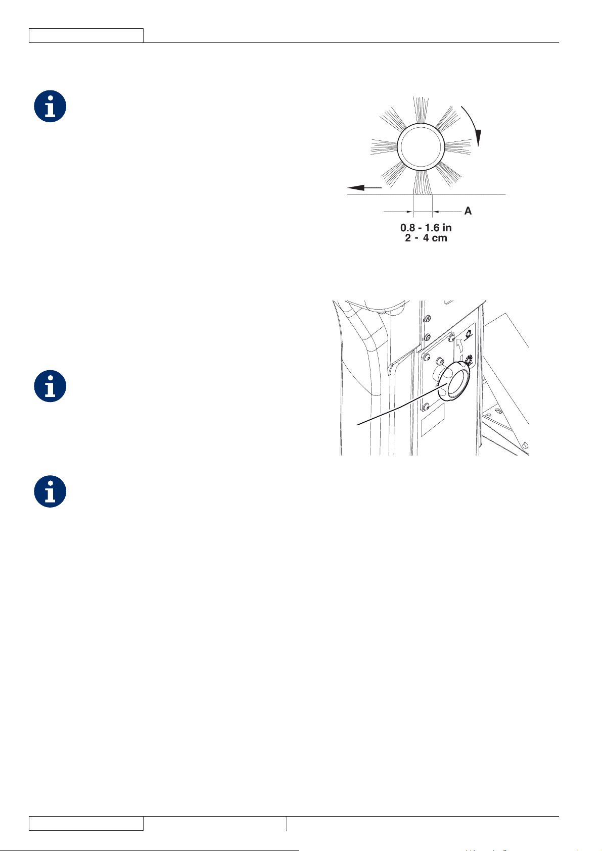
FRANÇAIS
MANUEL D’UTILISATION
CONTROLE ET REGLAGE DE LA HAUTEUR DU
BALAI CENTRAL
REMARQUE
La machine est livrée avec des balais de dureté
différente. La procédure ci-décrite est applicable à
tous les types de balais.
Contrôler la hauteur du sol du balai central, en procédant 1.
comme suit :
Amener la machine sur un sol plat.•
En gardant la machine en position d’arrêt, baisser •
le balai central et le faire tourner pendant quelques
secondes.
Arrêter et soulever le balai central, puis déplacer la •
machine et l’arrêter.
Contrôler que la largeur de la trace (A, Fig. 3) laissée •
par le balai central est comprise entre 2 et 4 cm dans
toute sa longueur.
Au cas où la trace (A) résulterait différente, procéder
au réglage de la hauteur du balai central, en procédant
comme suit.
Tourner la poignée (A, Fig. 4), en considérant que :2.
Pour augmenter la largeur de la trace, il faut tourner •
la poignée dans le sens contraire aux aiguilles d’une
montre.
Pour réduire la largeur de la trace, il faut soulever le •
balai au moyen du levier (80) et tourner la poignée
dans le sens des aiguilles d’une montre.
REMARQUE
Outre la fonction de réglage de la trace au sol, la
poignée a aussi la fonction de réglage du balai selon
l’usage des poils.
Exécuter à nouveau le point 1 pour vérifi er le réglage de la 3.
hauteur du sol du balai central.
Lorsque l’usure excessive du balai n’en permet plus 4.
le réglage, le remplacer comme prévu au paragraphe
suivant.
REMARQUE
Au cas où il ne serait pas possible de régler
correctement la trace (A, Fig. 3), car le balai
exerce une pression excessivement différente aux
extrémités de sa longueur, se référer au manuel
d’entretien pour la procédure de réglage.
P100216
Figure 3
A
P100217
Figure 4
20
1463388000(1)2008-05 A SR 1301 P
Page 55

REMPLACEMENT DU BALAI CENTRAL
REMARQUE
La machine est livrée avec des balais de dureté
différente. La procédure ci-décrite est applicable à
tous les types de balais.
ATTENTION !
L’utilisation de gants de travail est conseillée
pendant le remplacement du balai central à cause
de la présence éventuelle de débris tranchants
parmi les poils.
Amener la machine sur un sol plat et activer le frein de 1.
stationnement au moyen de la pédale (82) et du levier
(75).
Tourner la clé de contact (69) sur “0”, puis l’enlever.2.
Dégager le dispositif de retenue (8) et ouvrir le portillon 3.
droit (7).
Dévisser et enlever les pommeaux (A, Fig. 5).4.
Enlever le couvercle (A, Fig. 6) du logement du balai central.5.
Enlever le balai central (A, Fig. 7).6.
Contrôler que le moyeu entraîneur (A, Fig. 8) est propre et 7.
non obstrué par des objets (cordes, chiffons, etc.) enroulés
accidentellement.
Installer le nouveau balai central, en orientant les poils (B, 8.
Fig. 8) comme indiqué dans la fi gure.
Installer le nouveau balai central (C, Fig. 8) dans la 9.
machine et s’assurer que sa prise (D) s’insère dans le
relatif moyeu entraîneur (A).
Installer le couvercle (A, Fig. 6) du logement du balai 10.
central et visser les pommeaux (A, Fig. 5).
Fermer le portillon droit (7) et engager le dispositif de 11.
retenue (8).
Contrôler et régler la hauteur du balai central, comme 12.
indiqué au paragraphe précédent.
MANUEL D’UTILISATION
Figure 6
Figure 7
FRANÇAIS
P100219
P100220
Figure 5
P100218
Figure 8
SR 1301 P 1463388000(1)2008-05 A
P100221
21
Page 56
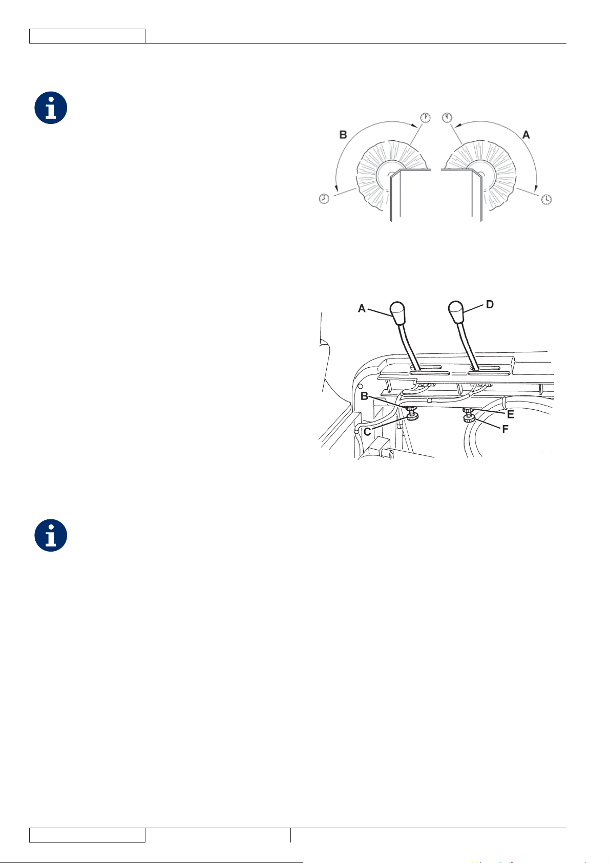
FRANÇAIS
MANUEL D’UTILISATION
CONTROLE ET REGLAGE DE LA HAUTEUR DES
BALAIS LATERAUX
REMARQUE
La machine est livrée avec des balais de dureté
différente. La procédure ci-décrite est applicable à
tous les types de balais.
Contrôler la hauteur du sol des brosses latérales, en 1.
procédant comme suit :
Amener la machine sur un sol plat.•
En gardant la machine en position d’arrêt, baisser les •
balais latéraux et les faire tourner pendant quelques
secondes.
Arrêter et soulever les balais latéraux, puis déplacer la •
machine.
Contrôler que les traces laissées par les balais latéraux •
sont, en extension et orientation, comme indiqué dans
la fi gure (A et B, Fig. 9).
Au cas où la trace résulterait différente, procéder au
réglage de la hauteur des balais latéraux, en procédant
comme suit.
Activer le frein de stationnement au moyen de la pédale 2.
(82) et du levier (75).
Tourner la clé de contact (69) sur “0”.3.
Ouvrir le coffre (23) et le bloquer au moyen de la tige de 4.
support (55).
Pour le balai latéral droit5. , agir sur le renvoi du levier (A,
Fig. 10) en dévissant l’embout (B) et en réglant le dispositif
de réglage (C) jusqu’à obtenir la trace correcte (A, Fig.
9). Enfi n, bloquer le dispositif de réglage au moyen de
l’embout (B, Fig. 10).
Pour le balai latéral gauche, agir sur le renvoi du levier
(D, Fig. 10) en dévissant l’embout (E) et en réglant le
dispositif de réglage (F) jusqu’à obtenir la trace (B, Fig.
9). Enfi n, bloquer le dispositif de réglage au moyen de
l’embout (E, Fig. 10).
Exécuter à nouveau le point 1 pour vérifi er le réglage de la 6.
hauteur du sol des brosses latérales.
Lorsque l’usure excessive du balai n’en permet plus 7.
le réglage, le remplacer comme prévu au paragraphe
suivant.
REMARQUE
Si besoin est, il est possible de régler aussi
l’inclinaison des balais latéraux (voir la procédure
dans le manuel d’entretien).
P100222
Figure 9
P100223
Figure 10
22
1463388000(1)2008-05 A SR 1301 P
Page 57
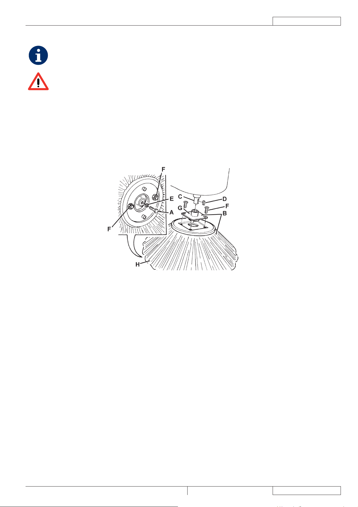
REMPLACEMENT DU BALAI LATERAL
REMARQUE
La machine est livrée avec des balais de dureté différente. La procédure ci-décrite est applicable à tous les types de
balais.
ATTENTION !
L’utilisation de gants de travail est conseillée pendant le remplacement du balai latéral à cause de la présence
éventuelle de débris tranchants parmi les poils.
Amener la machine sur un sol plat et activer le frein de stationnement au moyen de la pédale (82) et du levier (75).1.
Tourner la clé de contact (69) sur “0”.2.
Soulever le balai latéral concerné à l’aide du levier (77) ou (78).3.
A l’intérieur du balai latéral, enlever la vis (A, Fig. 11), puis enlever le balai latéral (B) avec le moyeu (B) en le dégageant de 4.
l’arbre (C).
Récupérer la clé (D) et la rondelle (E).
Sur banc, enlever les deux vis avec écrou (F, Fig. 11) et séparer le balai (H) du moyeu (G).5.
Installer le nouveau balai latéral (H, Fig. 11) sur le moyeu (G) et serrer les vis avec écrou (F).6.
Installer la clé (D), puis installer le nouveau balai latéral avec le moyeu (B, Fig. 11). Installer la rondelle (E) et serrer la vis (A).7.
Contrôler et régler la hauteur du balai latéral, comme indiqué au paragraphe précédent.8.
MANUEL D’UTILISATION
FRANÇAIS
Figure 11
P100224
SR 1301 P 1463388000(1)2008-05 A
23
Page 58

FRANÇAIS
MANUEL D’UTILISATION
NETTOYAGE ET CONTROLE DE L’INTEGRITE DU FILTRE A POUSSIERE EN PANNEAU
REMARQUE
Outre le fi ltre en papier standard, des fi ltres en polyester sont à disposition en tant qu’accessoires optionnels. La
procédure ci-décrite est applicable à chacun de ces types.
Amener la machine sur un sol plat et activer le frein de stationnement au moyen de la pédale (82) et du levier (75).1.
Tourner la clé de contact (69) sur “0”.2.
Ouvrir le coffre (23) et le bloquer au moyen de la tige de support (55).3.
Débrancher le connecteur (26) du moteur du système d’aspiration.4.
Dégager les dispositifs de retenue (A, Fig. 12) et enlever le coffre (B) du système d’aspiration.5.
Débrancher le connecteur (A, Fig. 13) du secoueur.6.
Dévisser les pommeaux (B, Fig. 13) et enlever le cadre de fi xation (C) du fi ltre.7.
Enlever le fi ltre à poussière (D, Fig. 13).8.
A l’extérieur, dans un endroit approprié, nettoyer le fi ltre en le secouant sur une surface horizontale et propre, en battant le 9.
côté (A, Fig. 14) opposé à celui du tamis (B).
Compléter le nettoyage à l’aide d’un jet perpendiculaire d’air comprimé (C) (6 bars maximum), en souffl ant uniquement du côté
protégé par le tamis (B) d’une distance minimum de 30 cm.
Contrôler que le corps du fi ltre n’a pas de déchirures.
Observer en outre les indications suivantes en fonction du fi ltre traité :
Filtre en papier (standard) : ne pas le nettoyer avec de l’eau ou du détergent pour ne pas risquer de l’endommager •
irrémédiablement.
Filtre en polyester (optionnel) : pour un nettoyage plus profond, il est possible de laver le fi ltre avec de l’eau et, •
éventuellement, avec des détergents non moussants. Ce type de lavage, même s’il est meilleur du point de vue qualitatif,
réduit la vie utile du fi ltre, lequel devra être remplacé plus souvent. L’utilisation de détergents pas adéquats peut
compromettre les caractéristiques fonctionnelles du fi ltre.
Si besoin est, nettoyer le long du périmètre du joint en caoutchouc (A, Fig. 15) du logement du fi ltre et contrôler que le joint est 10.
intact. Dans le cas contraire, en effectuer le remplacement.
Pour la repose, procéder dans l’ordre inverse de la dépose, en faisant attention aux indications suivantes :11.
Installer le fi ltre avec le tamis (B, Fig. 14) tourné vers le haut.•
A
AAB
Figure 12 Figure 13
P100225 P100226
24
P100227 P100228
Figure 14 Figure 15
1463388000(1)2008-05 A SR 1301 P
Page 59

NETTOYAGE ET CONTROLE DE L’INTEGRITE
DU FILTRE A POCHES
REMARQUE
Le nettoyage des fi ltres à poches en fi bre de
polyester s’effectue normalement par l’actionnement
du secoueur électrique livré avec la machine.
Si besoin est, ils peuvent être nettoyés à l’extérieur
en procédant comme suit.
Lorsque les conditions des surfaces fi ltrantes sont
compromises, il faut remplacer le fi ltre.
Amener la machine sur un sol plat et activer le frein de 1.
stationnement au moyen de la pédale (82) et du levier (75).
Tourner la clé de contact (69) sur “0”.2.
Ouvrir le coffre (23) et le bloquer au moyen de la tige de 3.
support (55).
Débrancher le connecteur (26) du moteur du système 4.
d’aspiration.
Dégager les dispositifs de retenue (A, Fig. 12) et enlever le 5.
coffre (B) du système d’aspiration.
Dévisser les pommeaux (A, Fig. 16) et enlever les étriers (B).6.
Débrancher le connecteur (B, Fig. 17) du secoueur et 7.
enlever le fi ltre à poussière (A).
A l’extérieur, dans un endroit approprié et avec l’opérateur 8.
préposé au nettoyage avec le vêtement de protection
(gants, masque, lunettes), procéder au démontage de la
surface fi ltrante en polyester, en procédant comme suit.
Enlever le moteur secoueur (A, Fig. 18) en dévissant les 9.
deux vis de fi xation correspondantes.
Ouvrir complètement le groupe support moteur secoueur 10.
(B, Fig. 18) en dégageant ainsi les tiges de tension (C) des
poches fi ltrantes.
Enlever toutes les tiges de tension des poches fi ltrantes 11.
(D, Fig. 18).
Dénouer la corde de fi xation supérieure (E, Fig. 18) 12.
du fi ltre à poches pour permettre la dépose du cadre
supérieur (F).
Enlever le séparateur intérieur poches (G, Fig. 18).13.
Nettoyer la surface en fi bre de polyester (H, Fig. 18) à 14.
partir du côté sale (en utilisant un aspirateur extérieur) en
l’étendant complètement ou en nettoyant chaque poche.
En même temps, aspirer les deux surfaces du séparateur
poches (G, Fig. 18), en enlevant tous les éventuels dépôts.
Contrôler que la surface fi ltrante n’a pas de déchirures ;
dans le cas contraire, la remplacer. Il est même possible
d’utiliser l’air comprimé (6 bars maximum) en dirigeant le
jet d’air du côté propre vers le côté sale.
ATTENTION !
Le nettoyage à l’eau du fi ltre n’est pas conseillé.
La fi bre en polyester pourrait se rétrécir et ne
plus être utilisable.
Si besoin est, nettoyer le long du périmètre du joint en 15.
caoutchouc (C, Fig. 17) et contrôler que le joint est intact.
Dans le cas contraire, en effectuer le remplacement.
Pour la repose, procéder dans l’ordre inverse de la 16.
dépose.
MANUEL D’UTILISATION
Figure 16
Figure 17
F
D
B
FRANÇAIS
P100229
P100230
E
G
H
C
A
Figure 18
SR 1301 P 1463388000(1)2008-05 A
P100231
25
Page 60

FRANÇAIS
MANUEL D’UTILISATION
CONTROLE DE LA HAUTEUR ET DU FONCTIONNEMENT DES VOLETS
Opérations préliminaires
Vider le conteneur déchets (en procédant comme prévu dans le manuel d’utilisation) pour éviter que le poids de déchets dans 1.
le conteneur infl uence le contrôle de la hauteur des volets.
Amener la machine sur un sol plat et adéquat en tant que plan de référence pour le contrôle de la hauteur des volets.2.
Activer le frein de stationnement au moyen de la pédale (82) et du levier (75).3.
Tourner la clé de contact (69) sur “0”.4.
Contrôle des volets latéraux
Dégager les dispositifs de retenue (8) et (6), puis ouvrir les portillons droit (7) et gauche (5).5.
Contrôler l’intégrité des volets latéraux (A, Fig. 19).6.
Remplacer les volets en présence de coupures (A, Fig. 20) supérieures à 20 mm ou de rupture / déchirures (B) supérieures à
10 mm (pour le remplacement des volets, se référer au manuel d’entretien).
Contrôler que la hauteur du sol des volets latéraux (A, Fig. 19) est comprise entre 0 et 3 mm (voir Fig. 21).7.
Si besoin est, desserrer les vis (B, Fig. 19) et régler la position des volets. Enfi n, serrer les vis (B).
Contrôle des volets avant et arrière
Enlever le balai central, en procédant comme indiqué au paragraphe spécifi que.8.
Contrôler l’intégrité des volets avant (A, Fig. 22) et arrière (B).9.
Remplacer les volets en présence de coupures (A, Fig. 20) supérieures à 20 mm ou de rupture / déchirures (B) supérieures à
10 mm (pour le remplacement des volets, se référer au manuel d’entretien).
Contrôler que les volets avant (A, Fig. 22) et arrière (B) touchent légèrement le sol et que, de toute façon, ils ne se détachent 10.
pas du sol (voir Fig. 24).
Si besoin est, desserrer les vis (C, Fig. 22) et régler la position des volets. Enfi n, serrer les vis (C).
Appuyer à fond sur la pédale du volet avant (81) et vérifi er que le volet avant se soulève d’environ 5 cm.11.
Relâcher la pédale et vérifi er que le volet revient à la position initiale et qu’il ne reste pas dans une position intermédiaire. Si
besoin est, régler le câble du volet (A, Fig. 23) au moyen du dispositif de réglage (B) qui se trouve sur le côté avant gauche du
volet (pour le remplacement du câble du volet avant, se référer au manuel d’entretien).
Repose
Pour la repose, procéder dans l’ordre inverse de la dépose.12.
Figure 19 Figure 20 Figure 21
P100232 P100233 P100234
26
Figure 22 Figure 23 Figure 24
P100235 P100236 P100237
1463388000(1)2008-05 A SR 1301 P
Page 61

CONTROLE DU NIVEAU D’HUILE DU SYSTEME
HYDRAULIQUE DE SOULEVEMENT DU
CONTENEUR DECHETS
ATTENTION !
Procédure à effectuer avec le conteneur déchets
(4) complètement rentré (comme indiqué dans la
fi gure).
Activer le frein de stationnement au moyen de la pédale 1.
(82) et du levier (75).
Tourner la clé de contact (69) sur “0”.2.
Ouvrir le coffre (23) et le bloquer au moyen de la tige de 3.
support (55).
Contrôler que le niveau d’huile dans le réservoir (41) est 4.
compris entre les repères de niveau minimum (MIN) et
maximum (MAX) indiqués dans la Fig. 25.
Si besoin est, faire l’appoint au moyen du bouchon (A, 5.
Fig. 25) en utilisant l’huile spécifi ée dans le paragraphe
Caractéristiques techniques.
Enlever la tige de support (55) et fermer le coffre (23).6.
CONTROLE DU NIVEAU D’HUILE DU SYSTEME
DE TRACTION
Activer le frein de stationnement au moyen de la pédale 1.
(82) et du levier (75).
Tourner la clé de contact (69) sur “0”.2.
Ouvrir le coffre (23) et le bloquer au moyen de la tige de 3.
support (55).
Contrôler que le niveau d’huile dans le réservoir (28) est 4.
compris entre les repères de niveau minimum (MIN) et
maximum (MAX) indiqués dans la Fig. 26.
Si besoin est, faire l’appoint au moyen du bouchon (A, Fig. 5.
26) avec l’huile moteur SAE 10W40.
Enlever la tige de support (55) et fermer le coffre (23).6.
MANUEL D’UTILISATION
Figure 25
MAX
MIN
FRANÇAIS
P100238
A
Figure 26
P100239
SR 1301 P 1463388000(1)2008-05 A
27
Page 62

FRANÇAIS
MANUEL D’UTILISATION
CONTROLE DU NIVEAU D’HUILE MOTEUR
Amener la machine sur un sol plat.1.
Activer le frein de stationnement au moyen de la pédale (82) et du levier (75).2.
Tourner la clé de contact (69) sur “0”.3.
Ouvrir le coffre (23) et le bloquer au moyen de la tige de support (55).4.
Enlever les vis (45), puis enlever la protection (44) du moteur en dégageant les dispositifs de retenue (46).5.
Dévisser le bouchon de niveau huile moteur (34) et le nettoyer avec un chiffon propre. Serrer complètement le bouchon de 6.
niveau (34) puis, après quelques secondes, le dévisser à nouveau et contrôler que le niveau d’huile est compris entre les
repères de niveau ADD (minimum) et FULL (maximum) (A, Fig. 27).
Si la quantité d’huile est inférieure au niveau minimum (ADD), enlever le bouchon de la goulotte de remplissage (35) et faire
l’appoint.
AVERTISSEMENT !
Remplir avec le même type d’huile présente dans le moteur.
Installer le bouchon de la goulotte de remplissage (35) et contrôler le niveau d’huile en procédant comme décrit 7.
précédemment.
Exécuter les étapes de 3 à 5 dans l’ordre inverse.
REMPLACEMENT DE L’HUILE MOTEUR
AVERTISSEMENT !
On conseille de remplacer l’huile lorsque le moteur est encore chaud, pour faciliter l’écoulement de l’huilemême.
Amener la machine sur un sol plat.1.
Activer le frein de stationnement au moyen de la pédale (82) et du levier (75).2.
Tourner la clé de contact (69) sur “0”.3.
Enlever les vis (48), puis enlever le panneau de protection latéral gauche (47) en dégageant les dispositifs de retenue (49).4.
Ouvrir le coffre (23) et le bloquer au moyen de la tige de support (55).5.
Enlever les vis (45), puis enlever la protection (44) du moteur en dégageant les dispositifs de retenue (49).6.
Enlever le bouchon (35) de la goulotte de remplissage de l’huile moteur.7.
Enlever le bouchon de vidange (38) de l’huile moteur du tuyau (40) et faire écouler toute l’huile moteur dans un bac de 8.
récupération adéquat.
AVERTISSEMENT !
L’huile moteur collectée doit être éliminée conformément aux normes d’hygiène de l’environnement en vigueur.
FULL
ADD
A
P100240
Figure 27
Installer le bouchon de vidange (38) de l’huile moteur au tuyau (40).9.
Verser l’huile nouvelle à travers l’ouverture de la goulotte de remplissage (35).10.
REMARQUE
Pour ce qui concerne le type et la quantité d’huile moteur, se référer au chapitre Caractéristiques techniques et au
manuel du moteur à essence.
Installer le bouchon (35) de la goulotte de remplissage.11.
Après quelques secondes, dévisser à nouveau le bouchon de niveau (34) puis contrôler que le niveau d’huile est compris 12.
entre les repères de niveau ADD (minimum) et FULL (maximum) (A, Fig. 27).
Si besoin est, faire l’appoint. Serrer le bouchon de niveau (34).
Exécuter les étapes de 4 à 6 dans l’ordre inverse.13.
28
1463388000(1)2008-05 A SR 1301 P
Page 63

MANUEL D’UTILISATION
FRANÇAIS
NETTOYAGE DU PREFILTRE A AIR MOTEUR ET ENTRETIEN DE LA CARTOUCHE DU FILTRE A AIR
MOTEUR
Amener la machine sur un sol plat.1.
Activer le frein de stationnement au moyen de la pédale (82) et du levier (75).2.
Tourner la clé de contact (69) sur “0”.3.
Enlever les vis (48), puis enlever le panneau de protection latéral gauche (47) en dégageant les dispositifs de retenue (49).4.
Nettoyer le préfi ltre à air moteur et / ou effectuer les opérations d’entretien de la cartouche (A, Fig. 28) du fi ltre à air, en 5.
procédant comme décrit dans le manuel du moteur à essence.
Installer à nouveau le panneau de protection latéral gauche (47).6.
NETTOYAGE DU CIRCUIT DE REFROIDISSEMENT DU MOTEUR
Amener la machine sur un sol plat.1.
Activer le frein de stationnement au moyen de la pédale (82) et du levier (75).2.
Tourner la clé de contact (69) sur “0”.3.
Enlever les vis (48), puis enlever le panneau de protection latéral gauche (47) en dégageant les dispositifs de retenue (49).4.
Enlever les vis (B, Fig. 28), puis enlever le convoyeur d’air (C).5.
Nettoyer le circuit de refroidissement (D) du moteur, en procédant comme indiqué dans le manuel du moteur à essence.6.
Installer à nouveau le panneau de protection latéral gauche (47).7.
A
B
D
BC
P100241
Figure 28
SR 1301 P 1463388000(1)2008-05 A
29
Page 64

FRANÇAIS
MANUEL D’UTILISATION
NETTOYAGE DU PARE-ETINCELLES
Amener la machine sur un sol plat.1.
Activer le frein de stationnement au moyen de la pédale (82) et du levier (75).2.
Tourner la clé de contact (69) sur “0”.3.
Enlever les vis (48), puis enlever le panneau de protection latéral gauche (47) en dégageant les dispositifs de retenue (49).4.
Enlever les vis de fi xation, puis enlever le terminal d’échappement (53) du moteur.5.
Nettoyer le pare-étincelles en procédant comme prévu dans le manuel du moteur à essence.6.
Exécuter les étapes 4 et 5 dans l’ordre inverse.7.
NETTOYAGE / REMPLACEMENT DE LA BOUGIE D’ALLUMAGE
Amener la machine sur un sol plat.1.
Activer le frein de stationnement au moyen de la pédale (82) et du levier (75).2.
Tourner la clé de contact (69) sur “0”.3.
Ouvrir le coffre (23) et le bloquer au moyen de la tige de support (55).4.
Enlever les vis (45), puis enlever la protection (44) du moteur en dégageant les dispositifs de retenue (46).5.
Nettoyer / remplacer la bougie d’allumage (51) en procédant comme prévu dans le manuel du moteur à essence.6.
Exécuter les étapes 4 et 5 dans l’ordre inverse.7.
CONTROLE / REMPLACEMENT / RETABLISSEMENT DES FUSIBLES
Amener la machine sur un sol plat et activer le frein de stationnement au moyen de la pédale (82) et du levier (75).1.
Tourner la clé de contact (69) sur “0”.2.
Ouvrir le coffre (23) et le bloquer au moyen de la tige de support (55).3.
Contrôle / remplacement des fusibles à lamelle
Enlever le couvercle (A, Fig. 29) et noter les positions des fusibles indiqués sur l’adhésif correspondant.4.
Contrôler / remplacer le fusible concerné parmi les suivants (B) :5.
Fusible F1 (30 A) : Circuit clé•
Fusible F2 (30 A) : Secoueur•
Fusible F3 (30 A) : Système d’aspiration•
Fusible F4 (30 A) : Pompe hydraulique•
Fusible F5 (10 A) : Feu clignotant (optionnel)•
Fusible F6 (10 A) : Feu de travail (optionnel)•
Fusible F7 (10 A) : Actionneur conteneur déchets•
Fusible F8 (30 A) : Fusible de réserve•
Contrôle / remplacement du fusible du système de chargement
Contrôler / remplacer le fusible FD (70 A) (50) du système de chargement6.
Contrôle des fusibles restaurables
Contrôler si un fusible parmi les suivants est débranché, puis attendre que le moteur correspondant refroidisse et le rétablir :7.
Fusible FA (C, Fig. 29) : Fusible restaurable moteur balai latéral droit•
Fusible FB (D) : Fusible restaurable moteur balai latéral gauche (optionnel)•
Fusible FC (E) : Fusible restaurable moteur balai central•
Repose
Pour la repose, procéder dans l’ordre inverse de la dépose.8.
A
E
C
D
B
30
P100249
Figure 29
1463388000(1)2008-05 A SR 1301 P
Page 65

MANUEL D’UTILISATION
DEPISTAGE DES PANNES
Problème Cause probable Remède
Le coffre (13) n’est pas correctement fermé. Fermer correctement le coffre.
Le niveau d’huile moteur est trop bas.
Le moteur ne démarre pas au moyen de
la clé de contact.
Le moteur s’arrête pendant le travail.
Les performances de collecte des déchets
/ poussières de la machine sont faibles.
En appuyant sur la pédale de marche,
la machine ne bouge pas ou bouge
lentement.
Le conteneur déchets ne se soulève pas.
Le conteneur déchets ne bascule pas.
Le conteneur déchets ne baisse pas.
Avec le coffre (13) du compartiment
moteur soulevé, le moteur à essence
reste en marche.
(*) Pour les instructions relatives, se référer au manuel du moteur à essence.
(**) Opération à effectuer auprès d’un Service après-vente Nilfi sk.
Le carburant est épuisé. Vérifi er que le réservoir (30) contient du carburant.
Le carburant n’arrive pas au carburateur.
La bougie ne produit aucune étincelle. Vérifi er que la bougie produit l’étincelle. (*)
Le niveau d’huile moteur est trop bas.
Le carburant est presque épuisé. Vérifi er que le réservoir (30) contient du carburant.
Le fi ltre carburant est sale. Nettoyer le fi ltre carburant. (*)
Le système d’aspiration est désactivé.
Le fi ltre à poussière est obstrué. Nettoyer le fi ltre à poussière.
Le conteneur déchets est plein. Vider le conteneur déchets (4).
Les volets ne sont plus intacts ni correctement
réglés.
La hauteur du sol des balais n’est pas
correctement réglée.
Le frein de stationnement est activé.
Le niveau d’huile du système hydraulique
n’est pas correct.
La poulie centrifuge ne fonctionne pas
correctement.
La pédale de marche n’est pas correctement
réglée.
Le niveau d’huile du système hydraulique
n’est pas correct.
Le fusible F4 ou F7 est interrompu. Remplacer le fusible.
Le fusible F7 est interrompu. Remplacer le fusible.
Le conteneur déchets n’est pas suffi samment
soulevé.
Le conteneur déchets n’a pas été
complètement ramené en position horizontale.
A cause de conditions climatiques
particulières, l’huile du système hydraulique
écoule très lentement à travers la soupape de
sécurité.
Le microinterrupteur de sécurité du coffre ne
fonctionne pas.
FRANÇAIS
Vérifi er que le niveau d’huile moteur est compris entre
les limites (*).
Vérifi er que le carburant arrive au carburateur et que
le fi ltre carburant est propre. (*)
Vérifi er que le niveau d’huile moteur est compris entre
les limites (*).
Activer le système d’aspiration au moyen de
l’interrupteur (56).
Contrôler l’intégrité et le réglage des volets (16, 17,
18, 19).
Régler la hauteur du sol des balais (10, 11, 12).
Contrôler que le frein de stationnement (84 et 76) est
désactivé.
Contrôler le niveau d’huile hydraulique dans le
réservoir (28).
Contrôler que la poulie centrifuge fonctionne
correctement (manchon d’accouplement moteur à
essence – pompe système de traction). (**)
Régler la pédale de marche. (**)
Contrôler le niveau d’huile hydraulique dans le
réservoir (41).
Soulever le conteneur déchets à plus de 300 mm.
Ramener le conteneur déchets en position
horizontale.
Attendre quelques minutes que l’huile du système
hydraulique écoule.
Réparer le microinterrupteur. (**)
Pour de plus amples informations, se référer au manuel d’entretien consultable auprès des Services après-vente Nilfi sk.
SR 1301 P 1463388000(1)2008-05 A
31
Page 66

FRANÇAIS
MANUEL D’UTILISATION
MISE A LA FERRAILLE
Effectuer la mise à la ferraille de la machine auprès d’un démolisseur autorisé.
Avant la mise à la ferraille, il est nécessaire de déposer et séparer les éléments suivants et les envoyer aux collectes sélectives,
conformément aux normes d’hygiène de l’environnement en vigueur :
Batteries –
Filtre à poussière en polyester –
Balais central et latéraux –
Huile moteur –
Huile système hydraulique –
Filtre à huile système hydraulique –
Tuyaux et pièces en matériel plastique –
Parties électriques et électroniques (*) –
(*) Pour la mise en décharge des parties électriques et électroniques, s’adresser auprès du centre Nilfi sk le plus proche.
32
1463388000(1)2008-05 A SR 1301 P
Page 67

USER MANUAL
ENGLISH
TABLE OF CONTENTS
INTRODUCTION .............................................................................................................................................................. 2
MANUAL PURPOSE AND CONTENTS .......................................................................................................................................... 2
TARGET ........................................................................................................................................................................................... 2
HOW TO KEEP THIS MANUAL ....................................................................................................................................................... 2
DECLARATION OF CONFORMITY ................................................................................................................................................ 2
IDENTIFICATION DATA ................................................................................................................................................................... 2
OTHER REFERENCE MANUALS ................................................................................................................................................... 2
SPARE PARTS AND MAINTENANCE ............................................................................................................................................. 2
CHANGES AND IMPROVEMENTS ................................................................................................................................................ 3
OPERATION CAPABILITIES ........................................................................................................................................................... 3
CONVENTIONS .............................................................................................................................................................................. 3
UNPACKING/DELIVERY ................................................................................................................................................. 3
SAFETY ........................................................................................................................................................................... 3
SYMBOLS ....................................................................................................................................................................................... 3
GENERAL INSTRUCTIONS ............................................................................................................................................................ 4
MACHINE DESCRIPTION ............................................................................................................................................... 6
MACHINE STRUCTURE ................................................................................................................................................................. 6
CONTROL PANEL ........................................................................................................................................................................... 8
ACCESSORIES/OPTIONS .............................................................................................................................................................. 9
TECHNICAL DATA ........................................................................................................................................................................... 9
WIRING DIAGRAM .........................................................................................................................................................................11
HOPPER LIFTING SYSTEM HYDRAULIC DIAGRAM ................................................................................................................. 13
DRIVE SYSTEM HYDRAULIC DIAGRAM .................................................................................................................................... 13
USE ................................................................................................................................................................................ 14
BEFORE STARTING THE MACHINE ........................................................................................................................................... 14
STARTING AND STOPPING THE MACHINE ............................................................................................................................... 14
MACHINE OPERATION ................................................................................................................................................................ 15
HOPPER EMPTYING .................................................................................................................................................................... 16
AFTER USING THE MACHINE ..................................................................................................................................................... 17
PUSHING/TOWING THE MACHINE ............................................................................................................................................. 17
WORKING LIGHT ADJUSTMENT ................................................................................................................................................. 17
MACHINE LONG INACTIVITY ...................................................................................................................................................... 17
FIRST PERIOD OF USE ............................................................................................................................................................... 17
MAINTENANCE ............................................................................................................................................................. 18
SCHEDULED MAINTENANCE TABLE ......................................................................................................................................... 18
MAIN BROOM HEIGHT CHECK AND ADJUSTMENT .................................................................................................................. 20
MAIN BROOM REPLACEMENT ................................................................................................................................................... 21
SIDE BROOM HEIGHT CHECK AND ADJUSTMENT .................................................................................................................. 22
SIDE BROOM REPLACEMENT .................................................................................................................................................... 23
PANEL DUST FILTER CLEANING AND INTEGRITY CHECK ...................................................................................................... 24
CLOSED POCKET FILTER CLEANING AND INTEGRITY CHECK .............................................................................................. 25
SKIRT HEIGHT AND OPERATION CHECK .................................................................................................................................. 26
HOPPER HYDRAULIC LIFTING SYSTEM OIL LEVEL CHECK ................................................................................................... 27
DRIVE SYSTEM OIL LEVEL CHECK ............................................................................................................................................ 27
ENGINE OIL LEVEL CHECK ......................................................................................................................................................... 28
ENGINE OIL CHANGE .................................................................................................................................................................. 28
ENGINE AIR PRE-FILTER CLEANING AND ENGINE AIR FILTER CARTRIDGE MAINTENANCE ............................................. 29
ENGINE COOLING SYSTEM CLEANING .................................................................................................................................... 29
SPARK SCREEN CLEANING........................................................................................................................................................ 30
SPARK PLUG CLEANING/REPLACEMENT ................................................................................................................................. 30
FUSE CHECK/REPLACEMENT/RESET ....................................................................................................................................... 30
TROUBLESHOOTING ................................................................................................................................................... 31
SCRAPPING .................................................................................................................................................................. 32
SR 1301 P 1463388000(1)2008-05 A
1
Page 68

ENGLISH
USER MANUAL
INTRODUCTION
NOTE
The numbers in brackets refer to the components shown in Machine Description chapter.
MANUAL PURPOSE AND CONTENTS
The purpose of this Manual is to provide the operator with all necessary information to use the machine properly in a safe and
autonomous way. It contains information about technical data, safety, operation, storage, maintenance, spare parts and disposal.
Before performing any procedure on the machine, the operators and qualifi ed technicians must read this Manual carefully. Contact
Nilfi sk in case of doubts regarding the interpretation of the instructions and for any further information.
TARGET
This Manual is intended for operators and technicians qualifi ed to perform the machine maintenance.
The operators must not perform procedures reserved for qualifi ed technicians. Nilfi sk will not be answerable for damages coming
from the non-observance of this prohibition.
HOW TO KEEP THIS MANUAL
The User Manual must be kept near the machine, inside an adequate case, away from liquids and other substances that can cause
damage to it.
DECLARATION OF CONFORMITY
The declaration of conformity, supplied with the machine, certifi es the machine conformity with the law in force.
NOTE
Two copies of the original declaration of conformity are provided together with the machine documentation.
IDENTIFICATION DATA
The machine model and serial number are marked on the plate (1).
The machine model year is written in the declaration of conformity and it is also indicated by the fi rst two fi gures of the machine
serial number.
The petrol engine model and serial number are marked on the plate (33).
This information is useful when ordering machine and engine spare parts. Use the following table to write down the machine and
engine identifi cation data for any further reference.
MACHINE model ...............................................................................
MACHINE serial number ...................................................................
ENGINE model ..................................................................................
ENGINE serial number ......................................................................
OTHER REFERENCE MANUALS
Petrol Engine Manual, supplied with the machine, to be considered an integral part of this Manual. –
Moreover, the following Manuals are available: –
Spare Parts List (supplied with the machine)•
Service Manual (that can be consulted at Nilfi sk Service Centers)•
SPARE PARTS AND MAINTENANCE
All necessary operating, maintenance and repair procedures must be performed by qualifi ed personnel or by Nilfi sk Service
Centers. Only original spare parts and accessories must be used.
Contact Nilfi sk for service or to order spare parts and accessories, specifying the machine model and serial number.
2
1463388000(1)2008-05 A SR 1301 P
Page 69

USER MANUAL
ENGLISH
CHANGES AND IMPROVEMENTS
Nilfi sk constantly improves its products and reserves the right to make changes and improvements at its discretion without being
obliged to apply such benefi ts to the machines that were previously sold.
Any change and/or addition of accessories must be approved and performed by Nilfi sk.
OPERATION CAPABILITIES
This sweeper has been designed and built to clean/sweep smooth and solid fl oors, and to collect dust and light debris, in civil and
industrial environments, under safe operation conditions by a qualifi ed operator.
CONVENTIONS
Forward, backward, front, rear, left or right are intended with reference to the operator’s position, that is to say on the driver’s seat
(54).
UNPACKING/DELIVERY
To unpack the machine carefully follow the instructions on the packing. –
Upon delivery check that the packing and the machine were not damaged during transportation. In case of visible damages, –
keep the packing and have it checked by the carrier that delivered it. Call the carrier immediately to fi ll in a damage claim.
Check that the machine is equipped with the following features: –
Technical documents:1.
Sweeper User Manual•
Petrol Engine Manual•
Sweeper Spare Parts List•
No. 1 10 A fuse2.
No. 1 70 A fuse3.
SAFETY
The following symbols indicate potentially dangerous situations. Always read this information carefully and take all necessary
precautions to safeguard people and property.
The operator’s cooperation is essential in order to prevent injury. No accident prevention program is effective without the total
cooperation of the person responsible for the machine operation. Most of the accidents that may occur in a factory, while working
or moving around, are caused by failure to comply with the simplest rules for exercising prudence. A careful and prudent operator is
the best guarantee against accidents and is essential for successful completion of any prevention program.
SYMBOLS
DANGER!
It indicates a dangerous situation with risk of death for the operator.
WARNING!
It indicates a potential risk of injury for people or damage to objects.
CAUTION!
It indicates a caution or a remark related to important or useful functions. Pay careful attention to the
paragraphs marked by this symbol.
NOTE
It indicates a remark related to important or useful functions.
CONSULTATION
It indicates the necessity to refer to the User Manual before performing any procedure.
SR 1301 P 1463388000(1)2008-05 A
3
Page 70

ENGLISH
USER MANUAL
GENERAL INSTRUCTIONS
Specifi c warnings and cautions to inform about potential damages to people and machine are shown below.
DANGER!
Before performing any maintenance, repair, cleaning or replacement procedure disconnect the battery –
connector, remove the ignition key and engage the parking brake.
This machine must be used by properly trained operators only. Children or disabled people cannot use this –
machine.
Do not wear jewels when working near electrical components. –
Keep the batteries away from sparks, fl ames and incandescent material. During the normal operation –
explosive gases are released.
Do not work under the lifted machine without supporting it with safety stands. –
When working under the open hood, ensure that it cannot be closed by accident. –
Do not operate the machine near toxic, dangerous, fl ammable and/or explosive powders, liquids or vapours. –
This machine is not suitable for collecting dangerous powders.
Be careful: fuel is highly fl ammable. –
Do not smoke or bring naked fl ames in the area where the machine is refuelled or where the fuel is stored. –
Refuel outdoors or in a well-ventilated area with the engine off. –
Turn off the engine and let it cool down for a few minutes, then remove the fuel tank plug. –
Leave at least a space of 4 cm in the fi ller to allow the fuel to expand. –
After refuelling, check that the fuel tank cap is fi rmly closed.
If any fuel is spilled while refuelling, clean the tank area and allow the vapours to evaporate before starting –
the engine.
Do not let fuel come into contact with the skin; do not breathe fuel vapours. Keep out of reach of children. –
Do not tilt the engine too much to avoid fuel spillage. –
When moving the machine, the fuel tank must not be full and the fuel tap must be closed. –
Do not lay any object on the engine. –
Stop the petrol engine before performing any procedure on it. To avoid any incidental start, disconnect the –
spark plug cap or disconnect the battery negative terminal.
Also see the GENERAL SAFETY RULES in the Petrol Engine Manual, which is to be considered an integral –
part of this Manual.
When lead batteries (WET) are installed on this machine, do not tilt the machine more than 30° from its –
horizontal position to not allow the highly corrosive acid to leak out of the batteries. When the machine is to
be tilted to perform maintenance procedures, remove the batteries.
WARNING!
Carbon monoxide (CO) can cause brain damage or death.
The internal combustion engine of this machine can emit carbon monoxide.
Do not inhale exhaust gas fumes.
Only use indoors when adequate ventilation is provided, and with the help of an assistant.
4
1463388000(1)2008-05 A SR 1301 P
Page 71

USER MANUAL
WARNING!
Carefully read all the instructions before performing any maintenance/repair procedure. –
Take all necessary precautions to prevent hair, jewels and loose clothes from being caught by the machine –
moving parts.
To avoid any unauthorized use of the machine, remove the ignition key. –
Do not leave the machine unattended without being sure that it cannot move independently. –
Do not use the machine on slopes with a gradient exceeding the specifi cations. –
Use only brooms supplied with the machine and those specifi ed in the User Manual. Using other brooms –
could reduce safety.
Before using the machine, close all doors and/or covers. –
Do not use the machine in excessively dusty areas. –
Do not wash the machine with direct or pressurised water jets, or with corrosive substances. –
Do not use compressed air to clean this type of machine, except for the fi lters (see the relevant paragraph). –
While using this machine, take care not to cause damage to other people, and children especially. –
Do not put any can containing fl uids on the machine. –
The machine storage temperature must be between 0°C and +40°C. –
The machine working temperature must be between 0°C and +40°C. –
The humidity must be between 30% and 95%. –
Always protect the machine against the sun, rain and bad weather, both under operation and inactivity –
condition. Store the machine indoors, in a dry place. This machine must be used in dry conditions, it must
not be used or kept outdoors in wet conditions.
Do not use the machine as a means of transport, or for pushing/towing. –
The machine maximum capacity, operator’s weight not included, is 110 kg (the weight of waste). –
Do not allow the brooms to operate while the machine is stationary to avoid damaging the fl oor. –
In case of fi re, possibly use a powder fi re extinguisher, not a water one. –
Do not bump into shelves or scaffoldings, especially where there is a risk of falling objects. –
Adjust the operation speed to suit the fl oor conditions. –
Do not use the machine on slopes with a gradient exceeding the specifi cations. –
This machine cannot be used on roads or public streets. –
Do not tamper with the machine safety guards. –
Follow the routine maintenance procedures scrupulously. –
Do not remove or modify the plates affi
In case of machine malfunctions, ensure that these are not due to lack of maintenance. Otherwise, request –
assistance from the authorised personnel or from an authorised Service Center.
If parts must be replaced, require ORIGINAL spare parts from an Authorised Dealer or Retailer. –
To ensure machine proper and safe operation, the scheduled maintenance shown in the relevant chapter of –
this Manual must be performed by the authorised personnel or by an authorised Service Center.
The machine must be disposed of properly, because of the presence of toxic-harmful materials (batteries, –
oils, plastics, etc.), which are subject to standards that require disposal in special centres (see the Scrapping
chapter).
While the engine is running, the silencer warms up; do not touch the silencer when it is hot to avoid burns or –
fi res.
Running the engine with an insuffi cient quantity of oil can seriously damage the engine. Check the oil level –
with the engine off and the machine on a level surface.
Never run the engine if the air fi lter is not installed, because the engine could be damaged. –
Technical service procedures on the engine must be performed by an authorised Dealer. –
Use only original spare parts or equivalent for the engine. Using spare parts of lower quality can seriously
damage the engine.
Also see the GENERAL SAFETY RULES in the Petrol Engine Manual, which is to be considered an integral –
part of this Manual.
xed to the machine. –
ENGLISH
SR 1301 P 1463388000(1)2008-05 A
5
Page 72
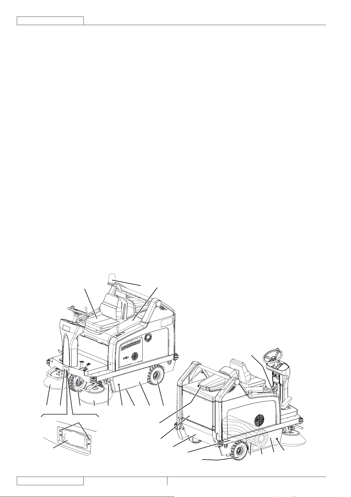
ENGLISH
USER MANUAL
MACHINE DESCRIPTION
MACHINE STRUCTURE
Serial number plate/technical data/conformity certifi cation1.
Flashing light (always on when the ignition key is turned to 2.
“I”) (optional)
Vacuum system motor cover3.
Hopper (empty it when it is full)4.
Left door (to be opened for performing maintenance 5.
procedures only)
Left closing fastener with safety mounting screw6.
Right door (for main broom removal)7.
Right fastener8.
Working light (optional)9.
Right side broom10.
Left side broom (optional)11.
Main broom12.
Engine compartment hood13.
Rear driving wheels on fi xed axle14.
Front steering wheel15.
Left side skirt16.
Right side skirt17.
Front skirt18.
Rear skirt19.
Dust fi lter container20.
Working light aiming adjusting screws21.
Engine exhaust manifold22.
Engine compartment hood (open)23.
Battery24.
Lamellar fuse box25.
Vacuum system motor connector26.
Drive system pump27.
Drive system oil tank28.
Petrol engine29.
Fuel tank30.
Fuel fi ller cap31.
Engine air fi lter32.
Petrol engine model and serial number33.
Engine oil level plug34.
Engine oil fi ller plug35.
Dynamotor36.
Hydraulic pump release screw (for machine pushing/37.
towing when the drive system is not available)
Engine oil drain plug38.
Engine start relay39.
Engine oil drain hose40.
Hopper hydraulic lifting system oil tank41.
Hopper lifting pump drive relay42.
Drive system motors43.
Petrol engine guard44.
Guard mounting screws
45.
Guard fasteners46.
Left side bulkhead47.
Bulkhead mounting screws48.
Bulkhead fasteners49.
Charging system fuse50.
Spark plug51.
Engine silencer52.
Engine exhaust end pipe53.
Driver’s seat54.
Hood support rod55.
Diode56.
Battery connection diagram57.
13254
10 9 15 11 18 6 16 5 14
21
3
20
9
1
4
19
14
12
17
8
7
P100206
6
1463388000(1)2008-05 A SR 1301 P
Page 73
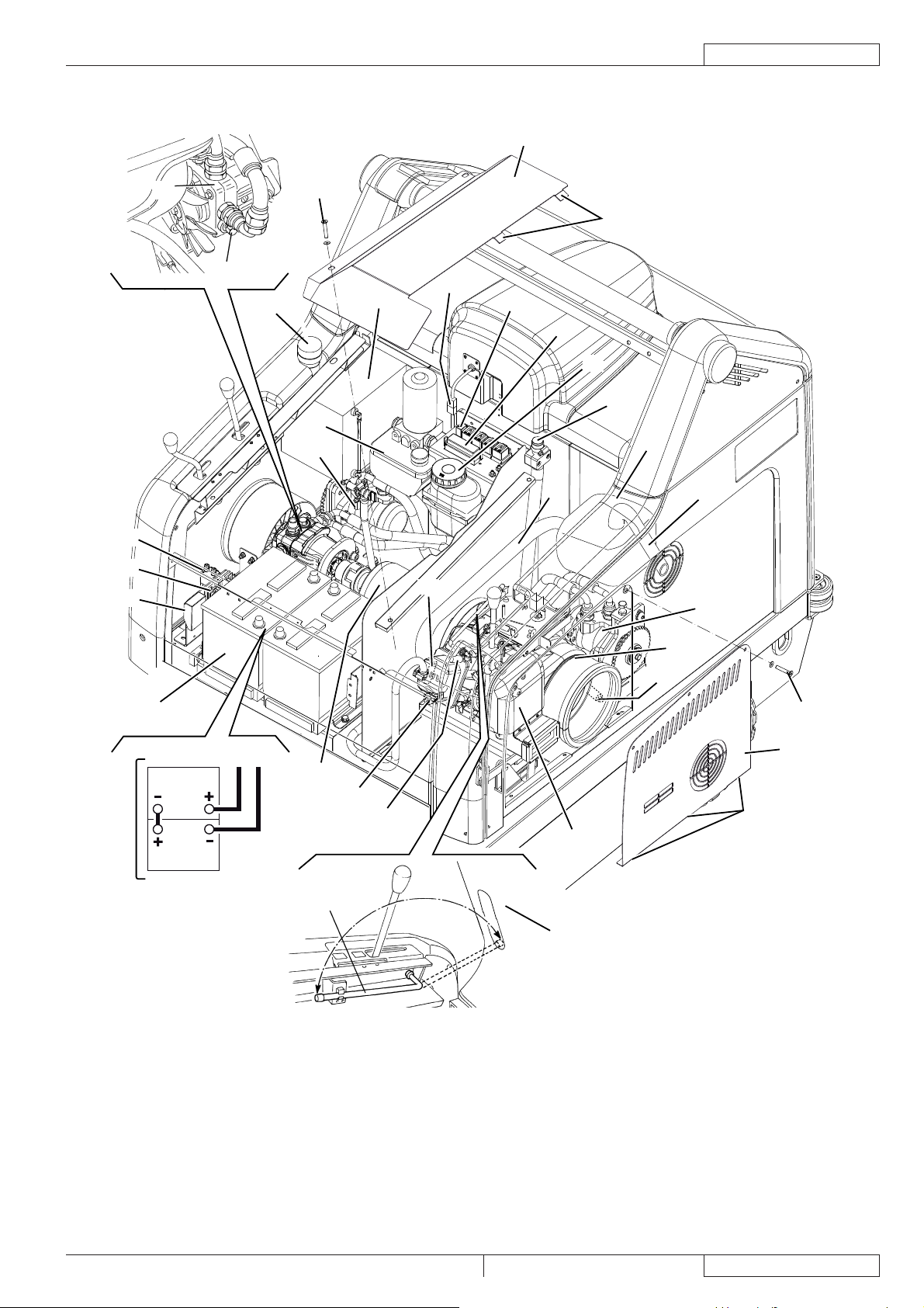
MACHINE STRUCTURE (Continues)
44
USER MANUAL
ENGLISH
39
56
50
27
37
31
43
45
41
30
33
26
42
22
46
25
28
35
52
53
43
57
24
12V
12V
36
55
34
51
29
38-40
48
47
49
32
23
P100207
SR 1301 P 1463388000(1)2008-05 A
7
Page 74

ENGLISH
CONTROL PANEL
Hopper lifting/lowering/dumping enabling switch61.
Horn switch62.
Position for working light switch (optional)63.
Main broom print adjusting knob64.
Turn it counter-clockwise to increase the broom print•
Turn it clockwise to decrease the broom print•
Position for optional switch65.
Switch66.
(Lower position) vacuum system activation•
(Upper position) fi lter shaker activation•
Hopper lifting/lowering switch67.
Hopper dumping switch68.
Ignition key69.
When turned to “0”, it turns the engine off and disables •
all functions.
When turned to “I”, it enables all machine functions; it •
also turns on the fl ashing light.
When completely turned clockwise (“Start” position), it •
starts the engine; when the engine is running release
the key, which returns to “I”.
USER MANUAL
Hour counter70.
Emergency push-button Press it in case of emergency 71.
to stop all the machine functions. To deactivate the
emergency push-button, turn it in the direction shown by
the arrow.
Steering wheel72.
Steering wheel tilting control knob73.
Choke lever74.
Parking brake lock control lever It locks the service brake 75.
(82) thus switching it to parking brake.
Forward/reverse gear pedal76.
Right side broom lifting/lowering lever77.
Left side broom lifting/lowering lever (optional)78.
Seat longitudinal position adjusting lever79.
Main broom lifting/lowering lever80.
Front skirt lifting pedal81.
Service brake pedal82.
82
81
73
72
74
75
64
76
80
79
69
70
61 62
77
71
63 65 66 67 68
78
P100208
8
1463388000(1)2008-05 A SR 1301 P
Page 75

USER MANUAL
ENGLISH
ACCESSORIES/OPTIONS
In addition to the standard components, the machine can be equipped with the following accessories/options, according to the
machine specifi c use:
Left side broom –
Main and side brooms with harder or softer bristles –
Antistatic polyester or polyester BIA C dust fi lter –
Closed pocket fi lter –
Flashing light –
Working light –
Non-marking skirts –
Non-marking wheels –
Protective roof –
For further information concerning the optional accessories, contact an authorised Retailer.
TECHNICAL DATA
General Values
Working width (with one side broom) 1,054 mm
Working width (with two side brooms) 1,308 mm
Machine length 1,776 mm
Machine width (with one side broom) 1,208 mm
Machine width (with two side brooms) 1,310 mm
Machine maximum height (at the steering wheel) 1,350 mm
Minimum distance from the fl oor (skirts not included) 60 mm
Hopper maximum lifting height 1,650 mm
Minimum/maximum dumping height 270/1,370 mm
Minimum turning radius 1,685 mm
Main broom size (diameter x length) 300 x 800 mm
Side broom diameter 500 mm
Maximum forward speed 7 km/h
Maximum reverse speed 3 km/h
Gradeability 20%
Hopper capacity 130 litres
Maximum weight liftable by the hopper 110 kg
Front axle weight in running conditions 297 kg
Rear axle weight in running conditions 446 kg
Machine kerb weight (with operator) 743 kg
Rear wheel specifi c pressure on the fl oor 1.2 N/mm
Front wheel specifi c pressure on the fl oor 1.1 N/mm
Front steering wheel (diameter x width) 305 x 92 mm
Rear driving wheel (diameter x width) 305 x 92 mm
Sound pressure level at workstation (ISO 11201, ISO 4871) (LpA) 80 dB(A) ±3 dB(A)
Machine output acoustic power (ISO 3744, ISO 4871) (LwA) 98 dB(A)
Vibration level at the operator’s arms (ISO 5349-1) (*) < 2.5 m/s
Vibration level at the operator’s body (ISO 2631-1) (*) < 0.5 m/s
(*) Under normal working conditions, on a level asphalt surface.
2
2
2
2
Petrol engine (*) Data
Make Briggs & Stratton
Model Vanguard 9 HP
Regulated power (ISO 1585) 6.7 kW
Working speed 3,100 ±50 rpm
Average consumption 1.7 litres/hour
Fuel tank capacity 8.5 litres
Oil type SAE 5 W 30 - SYNTHETIC API SJ
(*) For other petrol engine data/values, see the relevant Manual.
SR 1301 P 1463388000(1)2008-05 A
9
Page 76

ENGLISH
USER MANUAL
Dust vacuuming and fi ltering Values
Paper dust fi lter 15-20 m 3.6 m
2
Main broom compartment vacuum 10.9 mm/H2O
Electrical system Values
Batteries 2 x 12 V – 70 Ah
Vacuum system motor 310 W, 3000 rpm
Main broom motor 500 W, 550 rpm
Filter shaker motor 90 W, 5700 rpm
Closed pocket fi lter shaker motor (optional) 110 W, 3000 rpm
Drive system Values
Drive system pump SAUER HIDRO-GEAR BDP 10A
Drive system pump displacement 10.2 cm
Filling pump displacement 1.9 cm
3
3
Maximum working pressure 70 Bar
Maximum peak pressure 145 Bar
Hydraulic system oil tank capacity 0.8 litres
Hydraulic circuit total capacity 1.2 litres
Oil type SAE 10 W 40
Hopper hydraulic lifting system Values
Pump Parker 108 AE S32 – 24 V
Maximum pressure 110 Bar
Oil tank capacity 0.75 litres
Hydraulic circuit total capacity 1.4 litres
Hydraulic system oil (at ambient temperature above 10°C) AGIP Arnica 46 (*)
CAUTION!
If the machine is to be used at ambient temperatures below +10°C, the oil should be changed with equivalent oil
having a viscosity of 32 cSt. For temperatures below 0°C, use an oil with lower viscosity.
(*) See the oil technical data and reference data tables below.
TECHNICAL DATA REFERENCE DATA
AGIP ARNICA 46 32 ISO-L-HV
Viscosity at 40°C mm
Viscosity at 100°C mm
Viscosity index / 150 157 AISE 127
Flash point COC °C 215 202 ATOS Tab. P 002-0/I
Pour point °C -36 -36 BS 4231 HSE
Density at 15°C kg/l 0.87 0.865 CETOP RP 91 H HV
2
/s 45 32 ISO 11158
2
/s 7.97 6.40 AFNOR NF E 48603 HV
COMMERCIAL HYDRAULICS
Danieli Standard 0.000.001 (AGIP ARNICA 22, 46, 68)
EATON VICKERS I-286-S3
EATON VICKERS M-2950
DIN 51524 t.3 HVLP
LAMB LANDIS-CINCINNATI P68, P69, P70
LINDE
PARKER HANNIFIN (DENISON) HF-0
REXROTH RE 90220-1/11.02
SAUER-DANFOSS 520L0463
10
1463388000(1)2008-05 A SR 1301 P
Page 77

WIRING DIAGRAM
Key
BAT 24V battery
BE1 Pivoting light (optional)
BLK Engine frame
BZ1 Reverse gear buzzer - Horn
C1 Reverse gear buzzer capacitor
EBD Diode board
ES0 Engine ON relay
ES1 Hopper lifting pump relay
ES2 Hopper lowering pump relay
ES3 Filter shaker relay
ES4 Vacuum system relay
ES5 Start-up electromagnetic switch
ES6 Main broom electromagnetic switch
FA Right side broom circuit breaker (10A)
FB Left side broom circuit breaker (10 A) (optional)
FC Main broom circuit breaker (30 A)
FD Charging system fuse (70 A)
F1 Key fuse (30 A)
F2 Filter shaker fuse (30 A)
F3 Vacuum system fuse (30 A)
F4 Hopper lifting pump fuse (30 A)
F5 Reverse gear warning buzzer and pivoting light fuse (10 A)
F6 Working light fuse (10 A)
F7 Hopper dumping actuator fuse (10 A)
HM Hour counter
K1 Ignition key
L1 Working light (optional)
M1 Hopper lifting pump
M2 Hopper dumping actuator
M3 Filter shaker motor
M4 Vacuum system motor
M5 Right side broom motor
M6 Left side broom motor (optional)
M7 Main broom motor
M8 Dynamo
P1 Horn switch
SPK Engine spark plug
SW1 Vacuum system/fi lter shaker switch
SW2 Right side broom microswitch
SW3 Hopper lifting/lowering switch
SW4 Hopper dumping switch
SW5 Hopper movement enabling switch
SW6 Horizontal hopper microswitch
SW7 Closed hopper end-of-stroke microswitch
SW8 Lifted hopper microswitch
SW9 Opened hopper end-of-stroke microswitch
SW10 Reverse gear microswitch
SW11 Opened hood microswitch
SW12 Working light switch (optional)
SW13 Left side broom microswitch (optional)
SW14 Main broom microswitch
SWS Emergency push-button
Colour code
BK Black
BU Blue
BN Brown
GN Green
GY Grey
OG Orange
PK Pink
RD Red
VT Violet
WH White
YE Yellow
USER MANUAL
ENGLISH
SR 1301 P 1463388000(1)2008-05 A
11
Page 78

ENGLISH
USER MANUAL
WIRING DIAGRAM (Continues)
12
P100209
1463388000(1)2008-05 A SR 1301 P
Page 79

HOPPER LIFTING SYSTEM HYDRAULIC DIAGRAM
Key
Oil tank1.
Oil fi lter2.
Pump3.
Motor4.
Lifting cylinder safety valve5.
Hopper lifting cylinder6.
6
5
USER MANUAL
ENGLISH
200 BAR
110 BAR
750cc / HYDRAULIC OIL 32 cSt
1
DRIVE SYSTEM HYDRAULIC DIAGRAM
Key
Oil tank1.
Oil fi lter2.
Pump3.
Motors4.
200 BAR
3
70 BAR
4
2
P100210
4
3000
RPM
100
MICRON
10,2 CC/REV.
2
AB
88 CC/REV.
A
88 CC/REV.
3
A
B
4
B
1
SR 1301 P 1463388000(1)2008-05 A
P100211
13
Page 80
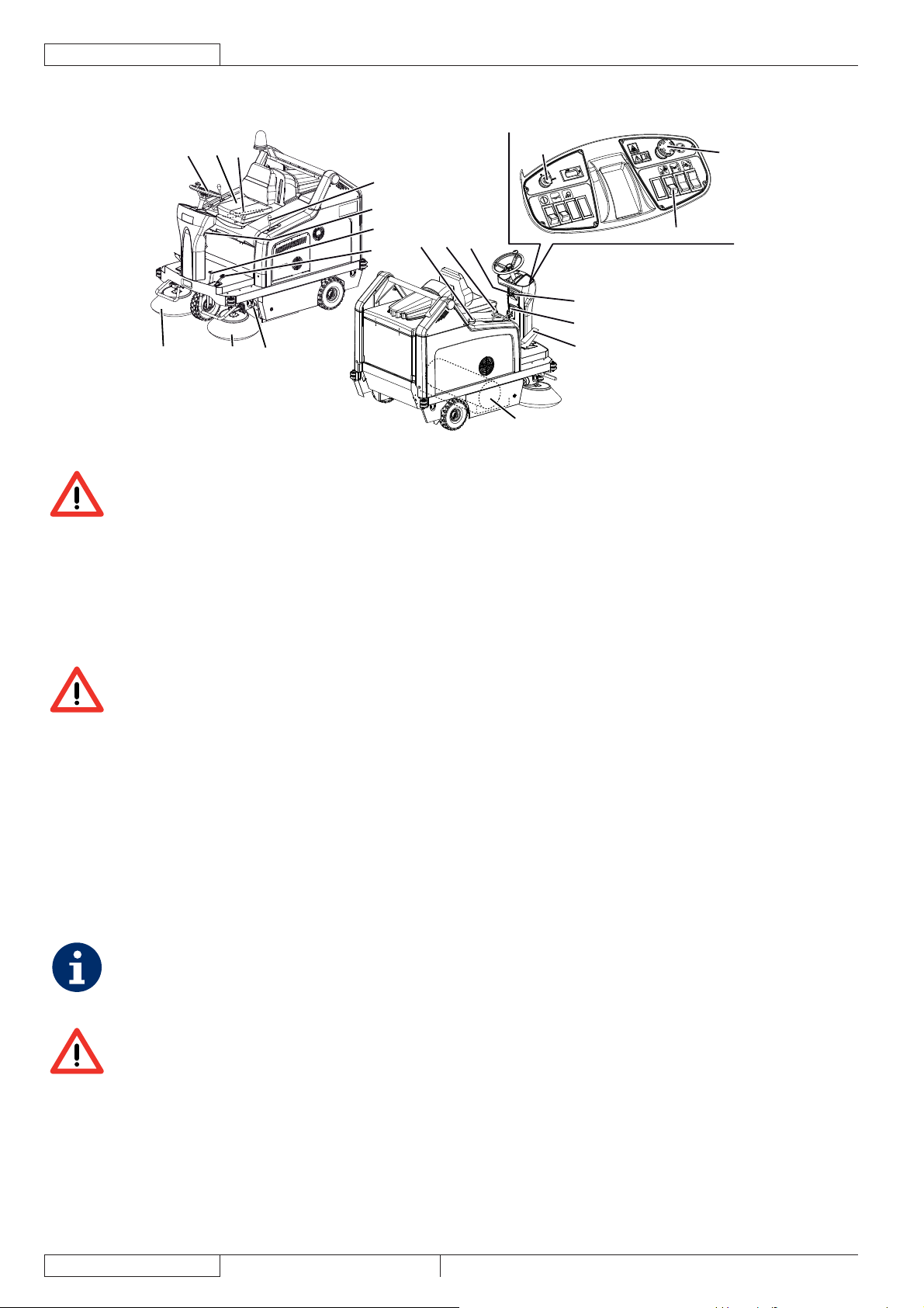
USE
ENGLISH
USER MANUAL
72
54
79
69
80
73
82
81
31
78
75
74
77
10 11
18
76
12
WARNING!
On some points of the machine there are some adhesive plates indicating:
DANGER –
WARNING –
CAUTION –
CONSULTATION –
While reading this Manual, the operator must pay careful attention to the symbols shown on the plates.
Do not cover these plates for any reason and immediately replace them if they are damaged.
71
66
P100212
BEFORE STARTING THE MACHINE
If it is necessary, unscrew the plug (31) and refuel the machine.1.
WARNING!
Leave at least a space of 4 cm in the fi ller to allow the fuel to expand.
Make sure that there are no open doors/hoods and that the machine is in normal operating conditions.2.
If the machine has not been used after being transported, check that all the blocks used for the transportation have been 3.
removed.
STARTING AND STOPPING THE MACHINE
Starting the machine
Sit on the driver’s seat (54), then adjust the seat in order to reach a comfortable position by using the lever (79).1.
Unlock the knob (73) by pulling it, then tilt the steering wheel (72) in order to reach a comfortable position. After the adjustment, 2.
release the knob (73) and slightly move the steering wheel to lock it.
Engage the parking brake with the pedal (82) and the lever (75).3.
Lift the main and side brooms with the levers (80), (77), (78).4.
Pull the engine choke lever (74).5.
NOTE
Do not use the choke lever if the engine is hot and if the air temperature is suffi ciently high.
Start the engine with the ignition key (69). When the engine starts, release the ignition key immediately.6.
WARNING!
When starting the engine with the ignition key (69) do not press the drive pedal (76).
14
1463388000(1)2008-05 A SR 1301 P
Page 81

USER MANUAL
After the ignition, let the engine run for a few seconds, then release the choke lever (74).7.
Let the engine warm up for a few minutes.8.
Disengage the parking brake by pressing the pedal (82) and by disengaging the lever (75).9.
Drive the machine to the working area, by keeping the hands on the steering wheel (72) and pressing the pedal (76) on the 10.
front side to move forward and on the rear side to move backward.
The drive speed can be adjusted from zero to maximum speed by increasing the pressure on the pedal.
Lower the main broom with the lever (80), then turn on the vacuum system by pressing the lower part of the switch (66).11.
Lower the right side broom with the lever (77).12.
If equipped, lower the left side broom with the lever (78).13.
NOTE
The brooms (10, 11, 12) can be lowered and lifted even when the machine is moving.
The brooms do not turn when they are lifted.
Start sweeping by turning the steering wheel (72) and moving the machine forward by pressing the pedal (76).14.
Stopping the machine
To stop the machine, release the pedal (76).15.
To stop the machine quickly, also press the service brake pedal (82).
In case of emergency, press the emergency push-button (71) to immediately stop the machine.
To deactivate the emergency push-button (71), turn it in the direction shown by the arrow.
Lift the main and side brooms with the levers (80), (77), (78).16.
Turn off the vacuum system with the switch (66).17.
Turn off the machine by turning the ignition key (69) to “0”, then remove it.18.
Engage the parking brake by pressing the pedal (82), then engage the brake lock control lever (75).19.
MACHINE OPERATION
Avoid stopping for a long time with the machine in the same position and the brooms turning: this could create unwanted 1.
marks on the fl oor.
To collect light and bulky waste materials, lift the front skirt (18) by pressing the pedal (81); take into consideration that the 2.
machine vacuum capability is reduced when the front skirt is lifted.
WARNING!
When operating on wet fl oors, it is essential to turn off the vacuum system by pressing the switch (66) to
prevent the dust fi lter from being damaged.
ENGLISH
For machine proper operation, the dust fi lter must be as clean as possible. To clean the dust fi lter while sweeping, turn on the 3.
fi lter shaker for a short interval by pressing the upper part of the switch (66), then turn on the vacuum system by pressing the
lower part of the switch (66).
While working, repeat the procedure every 10 minutes on average (depending on the dustiness of the area to be cleaned).
NOTE
This procedure can also be performed when the machine is moving.
CAUTION!
When the dust fi lter is clogged and/or the hopper is full, the machine cannot collect dust and debris anymore.
The hopper (4) should be dumped after each working period and whenever it is full (see the procedure in the next paragraph).4.
CAUTION!
The engine is equipped with a warning system to prevent damages to the engine itself in case the oil quantity in
the carter is insuffi cient. Before the oil level goes below the safety limit, the warning system automatically stops
the engine.
SR 1301 P 1463388000(1)2008-05 A
15
Page 82
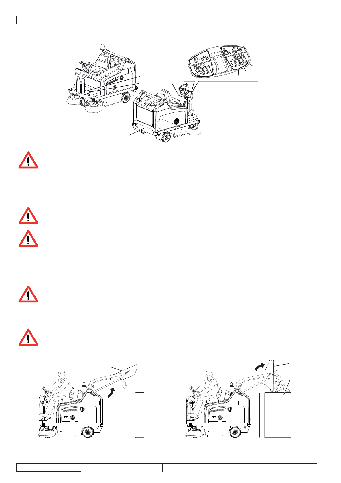
ENGLISH
HOPPER EMPTYING
WARNING!
Always empty the hopper when the engine is running.
Do not dump the hopper with the engine turned off, otherwise the battery discharges.
The hopper maximum dumping height is 1,370 mm (see Fig. 2).1.
To empty it, move the machine close to the dustbin and proceed as follows:2.
Lift the side and main brooms.•
Turn off the vacuum system with the switch (66).•
Turn on the fi lter shaker by pressing the upper part of the switch (66).•
WARNING!
Always perform this procedure on a level fl oor to avoid machine unbalance.
USER MANUAL
68
82
81
4
75
61
67
66
P100213
WARNING!
When lifting and emptying the hopper (4), engage the parking brake with the pedal (82) and the lever (75).
Keep people away from the machine and from the hopper (4) especially.3.
Press the enabling switch (61) while pressing the hopper lifting switch (67) to lift the hopper (A, Fig. 1) up to the desired 4.
position.
Press the enabling switch (61) and the dumping switch (68) of the hopper (B, Fig. 2) at the same time, and discharge all the 5.
debris in the dustbin (A).
CAUTION!
The hopper (B, Fig. 2) can be dumped only when lifted at a minimum height of 270 mm.
Press the enabling switch (61) and the hopper dumping switch (68) at the same time to bring the hopper back to horizontal 6.
position.
To lower the hopper, press the hopper enabling switch (61) while pressing the hopper lowering switch (67).7.
CAUTION!
The hopper cannot be lowered if it is not brought to horizontal position fi rst.
The machine is ready to start sweeping again.8.
A
P max
110 Kg
(242,5 lb)
B
A
16
1370 mm (54 in)
P100214 P100215
Figure 1 Figure 2
1463388000(1)2008-05 A SR 1301 P
Page 83

AFTER USING THE MACHINE
After working, before leaving the machine:
Turn on the fi lter shaker shortly, by pressing the upper part of the switch (66). –
Empty the hopper (4) (see the procedure in the previous paragraph). –
Lift the main broom with the lever (80). –
Lift the side brooms with the levers (77) and (78). –
Turn off the machine by turning the ignition key (69) to “0”, then remove it. –
Engage the parking brake by pressing the pedal (82), then engage the brake lock control lever (75). –
PUSHING/TOWING THE MACHINE
To easily push/tow the machine when it is off, proceed as follows:
Turn off the machine by turning the ignition key (69) to “0”. –
Open the hood (23) and fasten it with the support rod (55). –
Remove the screw (37). –
Remove the support rod (55) and close the hood (23). –
Push or tow the machine. –
After pushing/towing the machine, install the screw (37). –
WORKING LIGHT ADJUSTMENT
If necessary, adjust the working light beam aiming (9) with the screws (21).
MACHINE LONG INACTIVITY
If the machine is not going to be used for more than 30 days, proceed as follows:
Check that the machine storage area is dry and clean.1.
Disconnect the negative connector (-) of the batteries (24).2.
Handle the petrol engine (29) as shown in the relevant Manual.3.
USER MANUAL
ENGLISH
FIRST PERIOD OF USE
After the fi rst 5 hours perform the following procedures:
Check the fastening and connecting parts for proper tightening; check the visible parts for integrity and leakages.1.
Change the engine oil (see the procedure in Maintenance chapter).2.
SR 1301 P 1463388000(1)2008-05 A
17
Page 84

ENGLISH
USER MANUAL
MAINTENANCE
The lifespan of the machine and its maximum operating safety are ensured by correct and regular maintenance.
The following table provides the scheduled maintenance. The intervals shown may vary according to particular working conditions,
which are to be defi ned by the person in charge of the maintenance.
All scheduled or extraordinary maintenance procedures must be performed by qualifi ed personnel, or by an authorised Service
Center.
This Manual describes only the easiest and most common maintenance procedures.
For other maintenance procedures shown in the Scheduled Maintenance Table, refer to the Service Manual that can be consulted
at any Service Center.
WARNING!
To perform maintenance procedures, the machine must be off, the ignition key removed, and, if necessary, the
batteries must be disconnected.
Before performing any maintenance procedure, carefully read the instructions shown in Safety chapter.
SCHEDULED MAINTENANCE TABLE
Procedure
Engine oil level check
Battery fl uid level check
Side and main broom height check
Engine air pre-fi lter cleaning (3)
Frame dust fi lter cleaning and integrity
check
Hopper hydraulic lifting system oil
level check
Drive system oil level check
Skirt height and operation check
Fuel fi lter cleaning
Spark screen check and cleaning
Engine oil change (2)
Filter shaker operation check (1)
Brake adjustment (1)
Driving wheel chain cleaning and
tension check
Closed pocket fi lter cleaning and
integrity check
Vacuum system effi ciency check (1)
Driving belt visual inspection (1) (1)
Upon
delivery
After the fi rst
5 hours
Every 10
hours or
before use
Every 25
hours
Every 50
hours
Every
100
hours
(1)
Every
200
hours
Every
year
18
1463388000(1)2008-05 A SR 1301 P
Page 85

USER MANUAL
ENGLISH
Procedure
Spark plug check/cleaning
Nut and screw tightening check (1) (1)
Steering chain cleaning and tension
check
Safety system operation check (1)
Engine speed check (1)
Engine air fi lter element maintenance (3)
Spark plug replacement (2)
Engine cooling system cleaning (2)
Driving belt replacement (1) (5)
Hopper gasket integrity check (1)
Lifted hopper control microswitch
adjustment check
Horizontal hopper control microswitch
adjustment check
Valve clearance check/adjustment (4)
Hopper hydraulic lifting system and
drive system oil change
Upon
delivery
After the fi rst
5 hours
Every 10
hours or
before use
Every 25
hours
Every 50
hours
Every
100
hours
(1)
Every
200
hours
(1)
(1)
Every
(1) (6)
(1) For the relevant procedure, see the Service Manual.
(2) Or every year.
(3) Or more often in dusty areas.
(4) Maintenance procedures to be performed by an authorised Briggs & Stratton dealer.
(5) If the person in charge for the maintenance considers it necessary.
(6) Change the hydraulic system oil for the fi rst time after 500 hours, then every 2,000 hours or every year.
year
SR 1301 P 1463388000(1)2008-05 A
19
Page 86
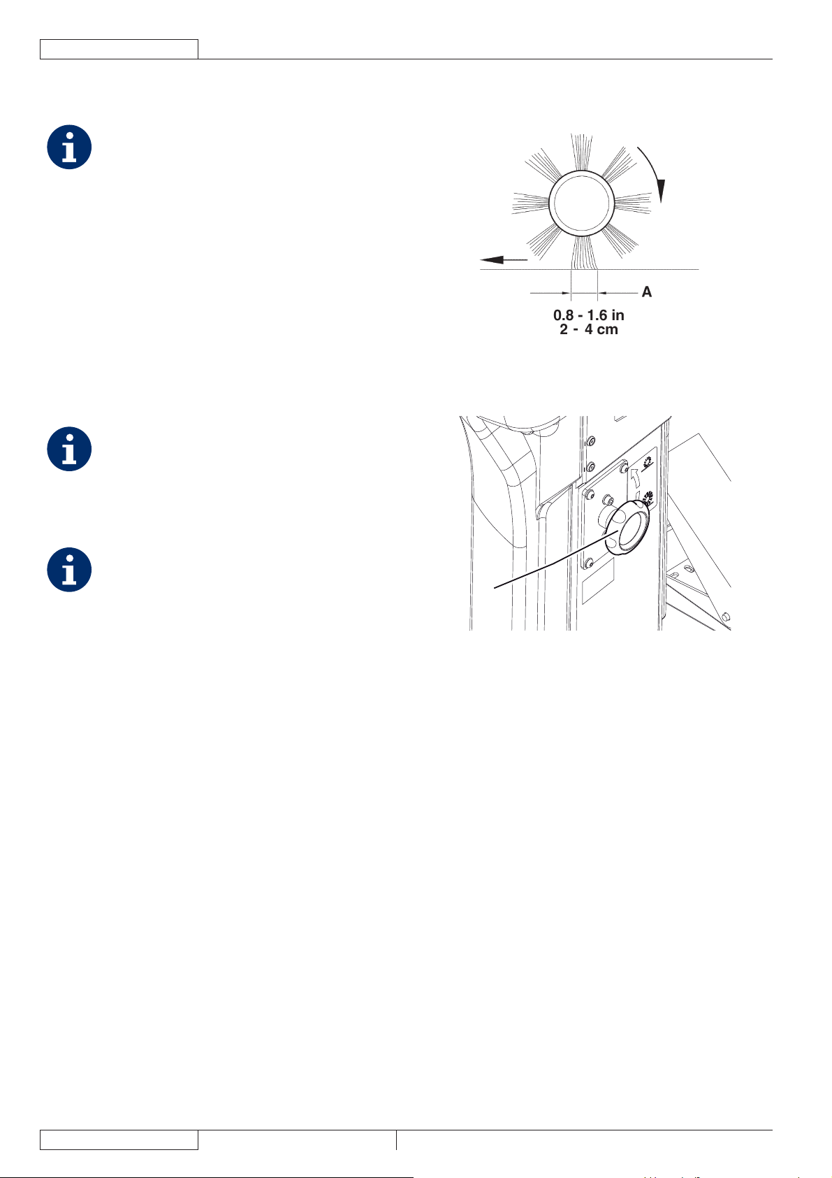
ENGLISH
USER MANUAL
MAIN BROOM HEIGHT CHECK AND
ADJUSTMENT
NOTE
Brooms with harder or softer bristles are available.
This procedure is applicable to all types of brooms.
Check the main broom distance from the fl oor as shown 1.
below:
Drive the machine on a level fl oor.•
Keep the machine stationary, lower the main broom •
and turn it on for a few seconds.
Stop and lift the main broom, then move the machine •
and switch it off.
Check that the main broom print (A, Fig. 3), along its •
length, is 2 to 4 cm wide.
If the print (A) is not within specifi cations, adjust the main
broom height according to the following procedure.
Turn the knob (A, Fig. 4) as shown below:2.
To increase the print width, turn the knob counter-•
clockwise
To decrease the print width, lift the broom with the lever •
(80) and turn the knob clockwise
NOTE
The knob can be used both to adjust the print and to
adjust the broom according to the bristle wear.
P100216
Figure 3
Perform step 1 again to check the proper adjustment of the 3.
main broom height.
When the broom is too worn to be adjusted, replace it as 4.
shown in the next paragraph.
NOTE
If it is not possible to adjust the print (A, Fig. 3)
properly, because the pressure on the fl oor at the
ends of the broom is different, refer to the Service
Manual.
A
P100217
Figure 4
20
1463388000(1)2008-05 A SR 1301 P
Page 87
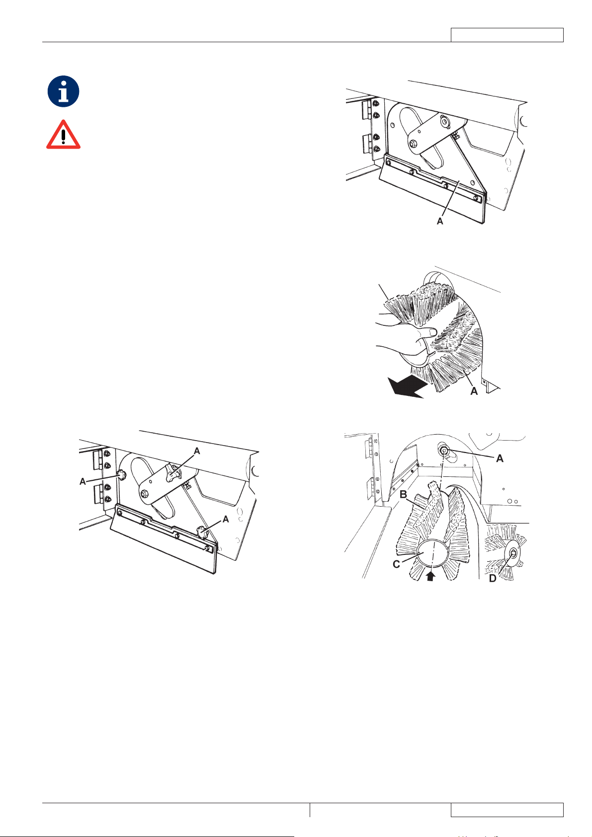
MAIN BROOM REPLACEMENT
NOTE
Brooms with harder or softer bristles are available.
This procedure is applicable to all types of brooms.
WARNING!
It is advisable to wear protective gloves when
replacing the main broom because there can be
sharp debris between the bristles.
Drive the machine on a level fl oor and engage the parking 1.
brake with the pedal (82) and the lever (75).
Turn the ignition key (69) to “0” and remove it.2.
Release the fastener (8) and open the right door (7).3.
Unscrew and remove the knobs (A, Fig. 5).4.
Remove the main broom compartment cover (A, Fig. 6).5.
Remove the main broom (A, Fig. 7).6.
Check that the drive hub (A, Fig. 8) is free from dirt or 7.
foreign materials (ropes, rags, etc.) accidentally rolled up.
The new main broom must be installed with the bristles 8.
rows (B, Fig. 8) bent as shown in the fi gure.
Install the new main broom (C, Fig. 8) and ensure that the 9.
mesh (D) correctly fi ts into the relevant drive hub (A).
Install the main broom compartment cover (A, Fig. 6) and 10.
tighten the knobs (A, Fig. 5).
Close the right door (7) and engage the fastener (8).11.
Check and adjust the main broom height as shown in the 12.
previous paragraph.
USER MANUAL
Figure 6
ENGLISH
P100219
Figure 5
P100218
P100220
Figure 7
P100221
Figure 8
SR 1301 P 1463388000(1)2008-05 A
21
Page 88
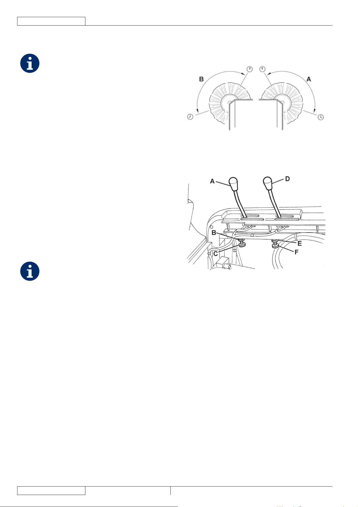
ENGLISH
USER MANUAL
SIDE BROOM HEIGHT CHECK AND
ADJUSTMENT
NOTE
Brooms with harder or softer bristles are available.
This procedure is applicable to all types of brooms.
Check the side broom distance from the fl oor, according to 1.
the following procedure:
Drive the machine on a level fl oor.•
Keep the machine stationary, lower the side brooms •
and turn them on for a few seconds.
Stop and lift the side brooms, then move the machine.•
Check that the side broom prints are as shown in the •
fi gure (A and B, Fig. 9).
If the print is not within specifi cations, adjust the side
broom height according to the following procedure.
Engage the parking brake with the pedal (82) and the lever 2.
(75).
Turn the ignition key (69) to “0”.3.
Open the hood (23) and fasten it with the support rod (55).4.
For the right side broom5. , operate on the idle gear of
the lever (A, Fig. 10), by loosening the ring nut (B) and by
adjusting the adjuster (C) until the correct print (A, Fig. 9)
is achieved. Then fasten the adjuster with the ring nut (B,
Fig. 10).
For the left side broom, operate on the idle gear of the
lever (D, Fig. 10), by loosening the ring nut (E) and by
adjusting the adjuster (F) until the correct print (B, Fig. 9)
is achieved. Then fasten the adjuster with the ring nut (E,
Fig. 10).
Perform step 1 again to check the proper adjustment of the 6.
side broom height.
When the broom is too worn to be adjusted, replace it as 7.
shown in the next paragraph.
NOTE
If necessary, the side broom tilting can be adjusted
too (see the procedure in the Service Manual).
P100222
Figure 9
P100223
Figure 10
22
1463388000(1)2008-05 A SR 1301 P
Page 89

SIDE BROOM REPLACEMENT
NOTE
Brooms with harder or softer bristles are available. This procedure is applicable to all types of brooms.
WARNING!
It is advisable to wear protective gloves when replacing the side broom because there can be sharp debris
between the bristles.
Drive the machine on a level fl oor and engage the parking brake with the pedal (82) and the lever (75).1.
Turn the ignition key (69) to “0”.2.
Lift the side broom which has to be removed, with the lever (77) or (78).3.
Remove the screw (A, Fig. 11) inside the side broom, then remove the side broom (B) with the hub (B) by disengaging it from 4.
the shaft (C).
Recover the key (D) and the washer (E).
At the workbench, remove the two screws (F, Fig. 11) and separate the broom (H) from the hub (G).5.
Install the new side broom (H, Fig. 11) onto the hub (G), and tighten the screws (F).6.
Install the key (D), then install the new side broom with the hub (B, Fig. 11). Install the washer (E) and tighten the screw (A).7.
Check and adjust the side broom height as shown in the previous paragraph.8.
USER MANUAL
ENGLISH
Figure 11
P100224
SR 1301 P 1463388000(1)2008-05 A
23
Page 90

ENGLISH
USER MANUAL
PANEL DUST FILTER CLEANING AND INTEGRITY CHECK
NOTE
Besides the standard paper fi lter, polyester fi lters are also available. The following procedure is applicable to each type of
fi lter.
Drive the machine on a level fl oor and engage the parking brake with the pedal (82) and the lever (75).1.
Turn the ignition key (69) to “0”.2.
Open the hood (23) and fasten it with the support rod (55).3.
Disconnect the vacuum system motor connector (26).4.
Release the fasteners (A, Fig. 12) and remove the vacuum system cover (B).5.
Disconnect the connector (A, Fig. 13) from the fi lter shaker.6.
Unscrew the knobs (B, Fig. 13) and remove the fi lter mounting frame (C).7.
Remove the dust fi lter (D, Fig. 13).8.
In an outdoor area, clean the fi lter by shaking it on a level and clean surface, tapping the side (A, Fig. 14) opposite to the wire 9.
gauze (B).
Complete the cleaning procedure by using compressed air (C) at maximum 6 Bar, blowing only from the side protected by the
wire gauze (B), at a minimum distance of 30 cm.
Check the fi lter body for tears.
According to the fi lter type, observe the following cautions:
Paper fi lter (standard): Do not use water or detergents to clean it, otherwise it can be damaged.•
Polyester fi lter (optional): For a better cleaning, it is allowed to wash the fi lter with water and non-lathering detergents. This •
provides better quality cleaning but reduces the life of the fi lter, which will have to be replaced more frequently. The use of
inadequate detergents can damage the fi lter.
If necessary, clean the fi lter compartment rubber gasket (A, Fig. 15) along its perimeter and check it for integrity. If necessary, 10.
replace it.
Assemble the components in the reverse order of disassembly, and note the following:11.
Install the fi lter with the wire gauze (B, Fig. 14) facing upwards.•
A
AAB
Figure 12 Figure 13
P100225 P100226
24
P100227 P100228
Figure 14 Figure 15
1463388000(1)2008-05 A SR 1301 P
Page 91

CLOSED POCKET FILTER CLEANING AND
INTEGRITY CHECK
NOTE
The polyester closed pocket fi lters are normally kept
clean by using the fi lter shaker supplied with the
machine.
If necessary, they can be cleaned externally
according to the following procedure.
When the fi ltering surfaces are worn, the fi lter must
be replaced.
Drive the machine on a level fl oor and engage the parking 1.
brake with the pedal (82) and the lever (75).
Turn the ignition key (69) to “0”.2.
Open the hood (23) and fasten it with the support rod (55).3.
Disconnect the vacuum system motor connector (26).4.
Release the fasteners (A, Fig. 12) and remove the vacuum 5.
system cover (B).
Unscrew the knobs (A, Fig. 16) and remove the brackets 6.
(B).
Disconnect the fi lter shaker connector (B, Fig. 17) and 7.
remove the dust fi lter (A).
In an outdoor area, and with the operator wearing suitable 8.
equipment (gloves, mask, glasses), remove the polyester
fi ltering surface, according to the following procedure.
Remove the fi lter shaker motor (A, Fig. 18) by unscrewing 9.
the two mounting screws.
Open the fi lter shaker motor support unit (B, Fig. 18) 10.
completely, and release the fi ltering pocket tension rods
(C).
Remove all the fi ltering pocket tension rods (D, Fig. 18).11.
Open the upper retaining cord (E, Fig. 18) of the closed 12.
pocket fi lter to remove it from the upper frame (F).
Remove the inner pocket separator (G, Fig. 18).13.
Clean the polyester fi bber surface (H, Fig. 18) from the 14.
dirty side (by using an external vacuum cleaner), spreading
it out completely or cleaning pocket by pocket. At the same
time, clean both surfaces of the pocket separator (G, Fig.
18), thus removing anything deposited on them. Check
the fi ltering surface for tears and replace it if necessary. It
is also possible to use compressed air (maximum 6 Bar),
blowing the air from the clean side towards the dirty side.
WARNING!
Do not wash the fi lter with water. The polyester
fi bber can shrink and become unusable.
If necessary, clean the fi lter compartment rubber gasket 15.
(C, Fig. 17) along its perimeter and check it for integrity. If
necessary, replace it.
Assemble the components in the reverse order of 16.
disassembly.
USER MANUAL
Figure 16
Figure 17
ENGLISH
P100229
P100230
E
G
H
F
D
C
B
A
Figure 18
SR 1301 P 1463388000(1)2008-05 A
P100231
25
Page 92

ENGLISH
USER MANUAL
SKIRT HEIGHT AND OPERATION CHECK
Preliminary procedure
Empty the hopper (as shown in the User Manual), because the weight of the waste inside the hopper can affect the skirt height 1.
check.
Drive the machine on a level fl oor that is suitable for checking the skirt height.2.
Engage the parking brake with the pedal (82) and the lever (75).3.
Turn the ignition key (69) to “0”.4.
Side skirt check
Release the fasteners (8 and 6), then open the right and left door (7 and 5).5.
Check the side skirts (A, Fig. 19) for integrity.6.
Replace the skirts when they have cuts (A, Fig. 20) larger than 20 mm or cracks/tears (B) larger than 10 mm (for skirt
replacement, refer to the Service Manual).
Check that the distance from the fl oor of the side skirts (A, Fig. 19) is within 0 - 3 mm (see Fig. 21).7.
If necessary, loosen the screws (B, Fig. 19) and adjust the skirt position. Then tighten the screws (B).
Front and rear skirt check
Remove the main broom as shown in the relevant paragraph.8.
Check the front (A, Fig. 22) and rear skirts (B) for integrity.9.
Replace the skirts when they have cuts (A, Fig. 20) larger than 20 mm or cracks/tears (B) larger than 10 mm (for skirt
replacement, refer to the Service Manual).
Check that the front (A, Fig. 22) and rear skirts (B) slightly rub on the fl oor (see Fig. 24).10.
If necessary, loosen the screws (C, Fig. 22) and adjust the skirt position. Then tighten the screws (C).
Press the front skirt lifting pedal (81) completely, and check that the front skirt lifts 5 cm approximately.11.
Release the pedal and check that the skirt does not remain in an intermediate position but returns to its initial position. If
necessary, adjust the skirt lifting cable (A, Fig. 23) with the adjuster (B) on the left front side of the skirt (for the front skirt
control cable replacement, see the Service Manual).
Reset
Assemble the components in the reverse order of disassembly.12.
P100232 P100233 P100234
Figure 19 Figure 20 Figure 21
26
Figure 22 Figure 23 Figure 24
P100235 P100236 P100237
1463388000(1)2008-05 A SR 1301 P
Page 93

HOPPER HYDRAULIC LIFTING SYSTEM OIL
LEVEL CHECK
WARNING!
This procedure must be performed with the
hopper (4) fully retracted (as shown in the fi gure).
Engage the parking brake with the pedal (82) and the lever 1.
(75).
Turn the ignition key (69) to “0”.2.
Open the hood (23) and fasten it with the support rod (55).3.
Check that the oil level in the tank (41) is between the 4.
minimum (MIN) and maximum (MAX) marks shown in Fig.
25.
If necessary, add oil through the plug (A, Fig. 25), using 5.
the oil specifi ed in Technical Data paragraph.
Remove the support rod (55) and close the hood (23).6.
DRIVE SYSTEM OIL LEVEL CHECK
Engage the parking brake with the pedal (82) and the lever 1.
(75).
Turn the ignition key (69) to “0”.2.
Open the hood (23) and fasten it with the support rod (55).3.
Check that the oil level in the tank (28) is between the 4.
minimum (MIN) and maximum (MAX) marks shown in Fig.
26.
If necessary, add engine oil SAE 10 W 40 through the plug 5.
(A, Fig. 26).
Remove the support rod (55) and close the hood (23).6.
USER MANUAL
Figure 25
MAX
ENGLISH
P100238
A
MIN
Figure 26
P100239
SR 1301 P 1463388000(1)2008-05 A
27
Page 94

ENGLISH
USER MANUAL
ENGINE OIL LEVEL CHECK
Drive the machine on a level fl oor.1.
Engage the parking brake with the pedal (82) and the lever (75).2.
Turn the ignition key (69) to “0”.3.
Open the hood (23) and fasten it with the support rod (55).4.
Remove the screws (45), then disengage the fasteners (46) to remove the engine guard (44).5.
Unscrew the engine oil level plug (34) and clean it with a clean cloth. Fully screw down the oil level plug (34) then unscrew it 6.
again after a few seconds, and check that the oil level is between the ADD (minimum level) and FULL (maximum level) marks
(A, Fig. 27).
If the oil level is lower than the minimum mark (ADD), remove the fi ller plug (35) and top up.
CAUTION!
Top up using the same type of oil as that in the engine.
Install the fi ller plug (35) and check the oil level as shown in the previous steps.7.
Perform steps 3 to 5 in the reverse order.
ENGINE OIL CHANGE
CAUTION!
It is advisable to change the oil when the engine is still hot, to make the oil downfl ow easier.
Drive the machine on a level fl oor.1.
Engage the parking brake with the pedal (82) and the lever (75).2.
Turn the ignition key (69) to “0”.3.
Remove the screws (48), then disengage the fasteners (49) to remove the left side bulkhead (47).4.
Open the hood (23) and fasten it with the support rod (55).5.
Remove the screws (45), then disengage the fasteners (49) to remove the engine guard (44).6.
Remove the engine oil fi ller plug (35).7.
Remove the engine oil drain plug (38) from the hose (40) and drain the oil into a suitable container.8.
CAUTION!
The discharged engine oil must be disposed of properly according to the Law in force.
Install the engine oil drain plug (38) to the hose (40).9.
Top up with new oil through the fi ller (35).10.
NOTE
As for engine oil type and quantity, see the Technical Data chapter and the Petrol Engine Manual.
FULL
ADD
A
P100240
Figure 27
Install the fi ller plug (35).11.
After a few seconds, unscrew the engine oil level plug (34) again and check that the oil level is between the ADD (minimum 12.
level) and FULL (maximum level) marks (A, Fig. 27).
If necessary top up. Screw down the oil level plug (34).
Perform steps 4 to 6 in the reverse order.13.
28
1463388000(1)2008-05 A SR 1301 P
Page 95

USER MANUAL
ENGLISH
ENGINE AIR PRE-FILTER CLEANING AND ENGINE AIR FILTER CARTRIDGE MAINTENANCE
Drive the machine on a level fl oor.1.
Engage the parking brake with the pedal (82) and the lever (75).2.
Turn the ignition key (69) to “0”.3.
Remove the screws (48), then disengage the fasteners (49) to remove the left side bulkhead (47).4.
Clean the engine air pre-fi lter and/or service the air fi lter element (A, Fig. 28), as shown in the Petrol Engine Manual.5.
Install the left side bulkhead (47).6.
ENGINE COOLING SYSTEM CLEANING
Drive the machine on a level fl oor.1.
Engage the parking brake with the pedal (82) and the lever (75).2.
Turn the ignition key (69) to “0”.3.
Remove the screws (48), then disengage the fasteners (49) to remove the left side bulkhead (47).4.
Remove the screws (B, Fig. 28), then remove the air defl ector (C).5.
Clean the engine cooling system (D), as shown in the Petrol Engine Manual.6.
Install the left side bulkhead (47).7.
A
B
D
BC
P100241
Figure 28
SR 1301 P 1463388000(1)2008-05 A
29
Page 96
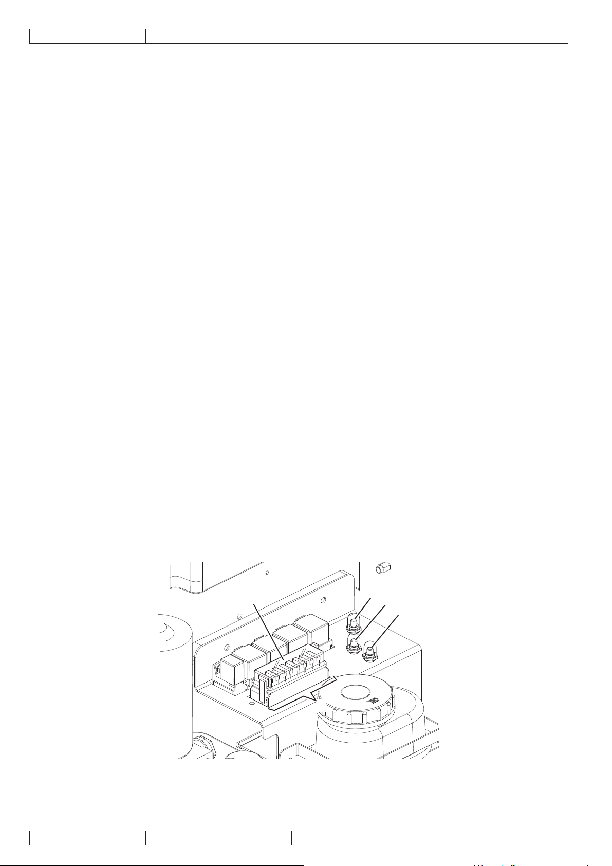
ENGLISH
USER MANUAL
SPARK SCREEN CLEANING
Drive the machine on a level fl oor.1.
Engage the parking brake with the pedal (82) and the lever (75).2.
Turn the ignition key (69) to “0”.3.
Remove the screws (48), then disengage the fasteners (49) to remove the left side bulkhead (47).4.
Remove the mounting screws, then remove the engine exhaust end pipe (53).5.
Clean the spark screen as shown in the Petrol Engine Manual.6.
Perform steps 4 and 5 in the reverse order.7.
SPARK PLUG CLEANING/REPLACEMENT
Drive the machine on a level fl oor.1.
Engage the parking brake with the pedal (82) and the lever (75).2.
Turn the ignition key (69) to “0”.3.
Open the hood (23) and fasten it with the support rod (55).4.
Remove the screws (45), then disengage the fasteners (46) to remove the engine guard (44).5.
Clean/replace the spark plug (51), as shown in the Petrol Engine Manual.6.
Perform steps 4 and 5 in the reverse order.7.
FUSE CHECK/REPLACEMENT/RESET
Drive the machine on a level fl oor and engage the parking brake with the pedal (82) and the lever (75).1.
Turn the ignition key (69) to “0”.2.
Open the hood (23) and fasten it with the support rod (55).3.
Lamellar fuse check/replacement
Remove the cover (A, Fig. 29) and mark the positions of the fuses shown on the adhesive.4.
Check/replace the relevant fuse among the following (B):5.
F1 fuse (30 A): Key circuit•
F2 fuse (30 A): Filter shaker•
F3 fuse (30 A): Vacuum system•
F4 fuse (30 A): Hydraulic pump•
F5 fuse (10 A): Flashing light (optional)•
F6 fuse (10 A): Working light (optional)•
F7 fuse (10 A): Hopper actuator•
F8 fuse (30 A): Spare fuse•
Charging system fuse check/replacement
Check/replace the FD (70 A) charging system fuse (50).6.
Circuit breaker check
Check for deactivation of one of the following fuses, then reset it after the relevant motor has cooled down:7.
FA fuse (C, Fig. 29): Right side broom motor circuit breaker•
FB fuse (D): Left side broom motor circuit breaker (optional)•
FC fuse (E): Main broom motor circuit breaker•
Assembly
Assemble the components in the reverse order of disassembly.8.
A
E
C
D
B
30
P100249
Figure 29
1463388000(1)2008-05 A SR 1301 P
Page 97

TROUBLESHOOTING
Trouble Possible cause Remedy
The hood (13) is not properly closed. Close the hood properly.
The engine oil level is too low. Check that the engine oil level is within the limits (*).
The engine does not start with the ignition
key.
The engine stops during operation.
The machine collects little debris/dust.
When pressing the drive pedal, the
machine does not move, or it moves
slowly.
The hopper does not lift.
The hopper does not dump.
The hopper does not lower.
When the engine compartment hood (13)
is open, the engine keeps running.
(*) For the relevant procedure, see the Petrol Engine Manual.
(**) Procedure to be performed by Nilfi sk Service Center.
The machine has run out of fuel. Check that there is fuel in the tank (30).
The fuel does not reach the carburettor.
The spark plug does not produce a spark. Check that the spark plug produces a spark. (*)
The engine oil level is too low. Check that the engine oil level is within the limits (*).
The machine is running out of fuel. Check that there is fuel in the tank (30).
The fuel fi lter is dirty. Clean the fuel fi lter. (*)
The vacuum system is turned off. Turn on the vacuum system with the switch (56).
The dust fi lter is clogged. Clean the dust fi lter.
The hopper is full. Empty the hopper (4).
The skirts are not integral or not properly
adjusted.
The broom height is not properly adjusted. Adjust the height of the brooms (10, 11, 12).
The parking brake is engaged.
The hydraulic system oil level is incorrect. Check the hydraulic system oil level in the tank (28).
The centrifugal pulley does not operate
properly.
The drive pedal is not properly adjusted. Adjust the drive pedal. (**)
The hydraulic system oil level is incorrect. Check the hydraulic system oil level in the tank (41).
The F4 or F7 fuse is open. Replace the fuse.
The F7 fuse is open. Replace the fuse.
The hopper is not lifted enough. Lift the hopper over 300 mm.
The hopper has not returned to horizontal
position.
In case of particular weather conditions, the
hydraulic system oil is slow in fl owing through
the safety valve.
The hood safety microswitch does not work. Repair the microswitch. (**)
USER MANUAL
Check that the fuel reaches the carburettor and that
the fuel fi lter is clean. (*)
Check the skirts (16, 17, 18, 19) for integrity and
proper adjustment.
Check that the parking brake (84 and 76) has been
released.
Check that the centrifugal pulley (petrol engine-drive
pump coupling joint) operates properly. (**)
Turn the hopper to horizontal position.
Wait a few moments to let the hydraulic system oil
fl ow.
ENGLISH
For further information, refer to the Service Manual, available at any Nilfi sk Service Center.
SR 1301 P 1463388000(1)2008-05 A
31
Page 98

ENGLISH
USER MANUAL
SCRAPPING
Have the machine scrapped by a qualifi ed scrapper.
Before scrapping the machine, remove and separate the following materials, which must be disposed of properly according to the
Law in force:
Batteries –
Polyester dust fi lter –
Main and side brooms –
Engine oil –
Hydraulic system oil –
Hydraulic system oil fi lter –
Plastic hoses and components –
Electrical and electronic components (*) –
(*) Refer to the nearest Nilfi sk Center especially when scrapping electrical and electronic components.
32
1463388000(1)2008-05 A SR 1301 P
Page 99

GEBRUIKSAANWIJZING
NEDERLANDS
INHOUDSOPGAVE
INLEIDING ....................................................................................................................................................................... 2
DOEL EN INHOUD VAN DEZE HANDLEIDING .............................................................................................................................. 2
BETREFFENDE PERSONEN ......................................................................................................................................................... 2
OPBERGEN VAN DE HANDLEIDING ............................................................................................................................................. 2
CONFORMITEITSVERKLARING .................................................................................................................................................... 2
IDENTIFICATIEGEGEVENS ........................................................................................................................................................... 2
ANDERE GEBRUIKERSHANDLEIDINGEN .................................................................................................................................... 2
VERVANGINGSONDERDELEN EN ONDERHOUD ....................................................................................................................... 2
MODIFICATIES EN VERBETERINGEN .......................................................................................................................................... 3
BEDRIJFSCAPACITEIT ................................................................................................................................................................... 3
ALGEMENE OPMERKINGEN ......................................................................................................................................................... 3
VERPAKKING VERWIJDEREN/AFLEVERING .............................................................................................................. 3
VEILIGHEID ..................................................................................................................................................................... 3
GEBRUIKTE SYMBOLEN ............................................................................................................................................................... 3
ALGEMENE INSTRUCTIES ............................................................................................................................................................ 4
BESCHRIJVING VAN DE MACHINE .............................................................................................................................. 6
BOUW VAN DE MACHINE .............................................................................................................................................................. 6
BEDIENINGSPANEEL EN KNOPPEN ............................................................................................................................................ 8
ACCESSOIRES / OPTIES ............................................................................................................................................................... 9
TECHNISCHE EIGENSCHAPPEN ................................................................................................................................................. 9
ELEKTRISCH SCHEMA .................................................................................................................................................................11
HYDRAULISCH SCHEMA VAN HET HEFSYSTEEM VOOR DE AFVALCONTAINER ................................................................. 13
HYDRAULISCH SCHEMA VAN DE AANDRIJVING ...................................................................................................................... 13
GEBRUIK ....................................................................................................................................................................... 14
VOOR HET STARTEN VAN DE MACHINE ................................................................................................................................... 14
DE MACHINE STARTEN EN STOPPEN ....................................................................................................................................... 14
MACHINE IN BEDRIJF .................................................................................................................................................................. 15
DE AFVALCONTAINER LEGEN .................................................................................................................................................... 16
NA GEBRUIK VAN DE MACHINE .................................................................................................................................................17
DUW-/TREKBEWEGING VAN DE MACHINE ............................................................................................................................... 17
DE BEDRIJFSVERLICHTING AFSTELLEN (optioneel) ................................................................................................................ 17
LANGE PERIODE VAN STILSTAND ............................................................................................................................................. 17
EERSTE GEBRUIKSPERIODE ..................................................................................................................................................... 17
ONDERHOUD ................................................................................................................................................................ 18
ONDERHOUDSSCHEMA ..............................................................................................................................................................18
DE HOOGTE VAN DE HOOFDBORSTEL CONTROLEREN EN AFSTELLEN ............................................................................ 20
DE HOOFDBORSTELVERVANGEN ............................................................................................................................................. 21
DE HOOGTE VAN DE ZIJBORSTELS CONTROLEREN EN AFSTELLEN .................................................................................. 22
DE ZIJBORSTEL VERVANGEN .................................................................................................................................................... 23
REINIGING EN CONTROLE OP BESCHADIGING VAN HET STOFPANEELFILTER .................................................................24
REINIGING EN CONTROLE OP BESCHADIGING VAN HET ZAKFILTER .................................................................................. 25
CONTROLE VAN DE HOOGTE EN WERKING VAN DE FLAPS ................................................................................................. 26
CONTROLE VAN HET PEIL VAN DE OLIE VOOR HET HYDRAULISCH SYSTEEM VOOR HET HEFFEN VAN DE
AFVALCONTAINER ....................................................................................................................................................................... 27
CONTROLE VAN HET OLIEPEIL IN HET AANDRIJFSYSTEEM ................................................................................................. 27
CONTROLE VAN HET MOTOROLIEPEIL .................................................................................................................................... 28
VERVERSING VAN DE MOTOROLIE ........................................................................................................................................... 28
REINIGING VAN HET LUCHTVOORFILTER VAN DE MOTOR EN ONDERHOUD VAN DE LUCHTFILTERHOUDER VAN DE
MOTOR .......................................................................................................................................................................................... 29
REINIGING VAN HET KOELSYSTEEM VAN DE MOTOR............................................................................................................ 29
REINIGING VAN DE VONKENVANGER ....................................................................................................................................... 30
REINIGING/VERVANGING VAN DE BOUGIE ............................................................................................................................. 30
CONTROLE / VERVANGING / RESETTEN VAN DE ZEKERINGEN ........................................................................................... 30
STORINGEN LOKALISEREN ....................................................................................................................................... 31
VERWIJDERING ............................................................................................................................................................ 32
SR 1301 P 1463388000(1)2008-05 A
1
Page 100

NEDERLANDS
GEBRUIKSAANWIJZING
INLEIDING
OPMERKING
De nummers tussen haakjes verwijzen naar de onderdelen die worden weergegeven in het hoofdstuk Beschrijving van
de machine.
DOEL EN INHOUD VAN DEZE HANDLEIDING
Deze handleiding heeft tot doel de bediener te voorzien van alle informatie die nodig is om deze machine op de juiste en veiligste
manier te gebruiken. Er staat informatie in over technische aspecten, de veiligheid, de werking, het stoppen, het onderhoud, de
vervangingsonderdelen en het verwijderen van de machine.
De bedieners en bevoegde monteurs die met deze machine werken, moeten de instructies in deze handleiding zorgvuldig lezen,
voordat ze met de machine aan het werk gaan. Neem bij twijfel over de juiste interpretatie van de instructies contact op met Nilfi sk
voor meer uitleg.
BETREFFENDE PERSONEN
Deze handleiding is bestemd voor de bediener van de machine en de technici die verantwoordelijk zijn voor het onderhoud van de
machine.
De bedieners mogen geen handelingen uitvoeren die alleen door bevoegde monteurs uitgevoerd mogen worden. Nilfi sk is niet
verantwoordelijk voor schade die is ontstaan uit het negeren van dit verbod.
OPBERGEN VAN DE HANDLEIDING
De instructiehandleiding moet in de juiste houder bij de machine worden opgeborgen. Er mogen geen vloeistoffen of andere
materialen bij komen zodat de handleiding goed leesbaar blijft.
CONFORMITEITSVERKLARING
De conformiteitsverklaring die bij de machine wordt geleverd is een verklaring dat de machine voldoet aan de geldende wetgeving.
OPMERKING
Twee kopieën van de oorspronkelijke verklaring van overeenstemming zijn verstrekt samen met de
machinedocumentatie.
IDENTIFICATIEGEGEVENS
Het serienummer en model van de machine staan op het plaatje (1).
Het productiejaar van de machine wordt in de conformiteitsverklaring aangegeven. Het productiejaar kan ook worden afgeleid uit de
eerste twee cijfers van het serienummer van de machine.
Het serienummer en het model van de benzinemotor staan op het plaatje (33).
Deze informatie heeft u nodig om vervangingsonderdelen voor de machine en de benzinemotor te bestellen. Gebruik de
onderstaande ruimte om de identifi catiegegevens van de machine en de benzinemotor te noteren.
Model MACHINE ...............................................................................
Serienummer MACHINE ...................................................................
Model MOTOR ..................................................................................
Serienummer MOTOR .......................................................................
ANDERE GEBRUIKERSHANDLEIDINGEN
Handleiding van de benzinemotor, bij de uitrusting van de machine, vormt een integraal deel van deze handleiding. –
Daarnaast zijn de volgende handleidingen leverbaar: –
Catalogus met vervangingsonderdelen (behoort tot de uitrusting van de machine)•
Werkplaatshandleiding (te raadplegen bij de servicecentra van Nilfi sk)•
VERVANGINGSONDERDELEN EN ONDERHOUD
Als er onderhouds- of reparatiewerkzaamheden aan de machine nodig zijn, moet u deze door bevoegd personeel of bij de
servicecentra van Nilfi sk laten uitvoeren. Er mogen alleen originele vervangingsonderdelen en accessoires worden gebruikt.
Als u hulp nodig heeft of vervangingsonderdelen en accessoires wilt bestellen bij Nilfi sk, zorg dan dat u het model en het
serienummer altijd bij de hand heeft.
2
1463388000(1)2008-05 A SR 1301 P
 Loading...