

Page 1

AMERICAN-LINCOLN
TECHNOLOGY
Operator's Manual
Beginning with Serial No. 690060
READ THIS BOOK
This book has important information for the use and safe operation of this machine. Failure
to read this book prior to operating or attempting any service or maintenance procedure to
your machine could result in injury to you or to other personnel; damage to the machine or to
other property could occur as well. you must have training in the operation of this machine
before using it. If you or your operator (s) cannot read English, have this manual explained
fully before attempting to operate this machine.
Si Ud. o sis operadores no pueden leer el Inglés, se hagen explicar este manual completamente
antes de tratar el manejo o servicio de esta máquina.
All directions given in this book are as seen from the operator's position at the rear of the machine.
For new books, write to:
Alto U.S., Inc., 1100 Haskins Road, Bowling Green, Ohio 43402
SMART 2000
Sweeper/scrubber
Part No. 2-86-00254 2001 Printed in the
American-Lincoln Technology® USA
Page 2

TABLE OF CONTENTS
SPECIFICA TIONS .................................................................................................................................. 1-4
MACHINE DIMENSIONS ........................................................................................................................1-6
ST ANDARD HARDWARE & TORQUE V ALUES...................................................................................... 1-7
HYDRAULIC TORQUE REQUIREMENTS ............................................................................................... 1-8
DECIMAL - METRIC CONVERSION T ABLE ...........................................................................................1-9
MACHINE PREP ARA TION ...................................................................................................................... 1-10
PREP ARING THE MACHINE FOR OPERA TION...............................................................................1-10
BA TTERY POWERED MACHINE PREP ARA TION............................................................................1-11
SAFETY INSTRUCTIONS .................................................................................................................1-12
OPERA TION OF CONTROLS AND GAUGES .........................................................................................1-15
LIGHT SWITCH................................................................................................................................. 1-15
HORN BUTTON ................................................................................................................................ 1-15
KEY SWITCH ................................................................................................................................... 1-15
HOUR METER.................................................................................................................................. 1-15
BA TTERY CONDITION METER ........................................................................................................1-16
BA TTERY CONDITION LIGHT...........................................................................................................1-16
SEA T POSITION ADJUSTMENT .......................................................................................................1-16
FIL TER SHAKER SWITCH ............................................................................................................... 1-17
DUST CONTROL SWITCH................................................................................................................1-17
MAIN BROOM AND SIDE BROOM SWITCH .................................................................................... 1-17
SIDE BROOM ADJUSTMENT...........................................................................................................1-17
MAIN BROOM ADJUSTMENT ..........................................................................................................1-17
SCRUB DECK SWITCH ...................................................................................................................1-18
SQUEEGEE SWITCH ......................................................................................................................1-18
SOLUTION CONTROL KNOB ........................................................................................................... 1-18
LOW SOLUTION LIGHT (WARNING LIGHT) ..................................................................................... 1-19
RECOVERY HIGH LIGHT (WARNING LIGHT)................................................................................... 1-19
P ARKING BRAKE ............................................................................................................................ 1-19
TURN SIGNAL (4-W AY) OPTION...................................................................................................... 1-19
HYDRAULIC RESERVOIR LEVEL SIGHT GAUGE...........................................................................1-19
ACCELERA TOR and DIRECTIONAL CONTROL PEDAL ................................................................... 1-20
BACK-UP ALARM SWITCH ..............................................................................................................1-20
FIL TER P ANEL KNOB ......................................................................................................................1-20
MAIN BROOM COMP ARTMENT DOOR ........................................................................................... 1-21
HOPPER LIFT SWITCH....................................................................................................................1-21
ESP SYSTEM OPERA TING INSTRUCTIONS .........................................................................................1-22
THE SCRUBBING SYSTEM - HOW IT WORKS ............................................................................... 1-22
THE NON-RECYCLING OR ST ANDARD SCRUBBING SYSTEM - HOW IT WORKS........................1-22
RECOVERY OR ESP SYSTEM - HOW IT WORKS .........................................................................1-22
OPERA TING INSTRUCTIONS ................................................................................................................. 1-23
BEFORE ST ARTING THE ENGINE...................................................................................................1-23
PRE-ST ART CHECKLIST.................................................................................................................. 1-23
ST ARTING BA TTERY MACHINES ....................................................................................................1-23
POST-OPERA TION CHECKLIST.......................................................................................................1-23
SERVICE CHART ................................................................................................................................... 1-24
HELPFUL HINTS FOR CLEANING OPERA TION ..................................................................................... 1-26
SERVICE PRECAUTIONS ...................................................................................................................... 1-27
SERVICE INSTRUCTIONS ...................................................................................................................... 1-28
MAIN BROOM .................................................................................................................................. 1-28
CHECKING THE MAIN BROOM SWEEP P A TTERN......................................................................... 1-28
ADJUSTING THE MAIN BROOM HEIGHT ........................................................................................ 1-28
REPLACING THE MAIN BROOM ..................................................................................................... 1-28
MAIN BROOM LEVEL ADJUSTMENT ..............................................................................................1-28
SIDE BROOM .................................................................................................................................. 1-29
CHECKING THE SIDE BROOM SWEEP P A TTERN .........................................................................1-29
AMERICAN-LINCOLN TECHNOLOGY 1 - 1
SMART 2000
Page 3

TABLE OF CONTENTS
REPLACING THE SIDE BROOM......................................................................................................1-29
HOPPER .......................................................................................................................................... 1-30
CLEANING THE HOPPER................................................................................................................1-30
ADJUSTING THE HOPPER SWITCH................................................................................................1-30
DUST CONTROL FIL TER..................................................................................................................1-30
CHECKING THE DUST CONTROL FIL TER ....................................................................................... 1-30
CLEANING THE DUST CONTROL FIL TER........................................................................................1-30
REPLACING THE DUST CONTROL FIL TER .....................................................................................1-31
DUST FLAPS ...................................................................................................................................1-31
CHECKING THE DUST FLAPS ........................................................................................................ 1-31
ADJUSTING THE DUST FLAPS ....................................................................................................... 1-31
BRAKES .......................................................................................................................................... 1-32
ADJUSTING THE BRAKE PEDAL ....................................................................................................1-32
ADJUSTING THE BRAKES ..............................................................................................................1-32
ADJUSTING THE FOOT THROTTLE SWITCH...................................................................................1-32
GENERAL MACHINE MAINTENANCE.................................................................................................... 1-33
FILLING THE HYDRAULIC RESERVOIR ..........................................................................................1-33
CLEANING THE HYDRAULIC SYSTEM ...........................................................................................1-33
REPLACING THE RETURN FIL TER ELEMENT ................................................................................ 1-33
REPLACING THE SCRUB BRUSH ................................................................................................... 1-34
ADJUSTING THE SCRUD DECK ......................................................................................................1-34
COVERS AND LATCHES ................................................................................................................. 1-34
SOLUTION LOW WARNING LIGHT ..................................................................................................1-34
RECOVERY HIGH WARNING LIGHT ...............................................................................................1-34
SOLUTION CONTROL ...................................................................................................................... 1-34
RECYCLING PUMP ESP SYSTEM..................................................................................................1-35
RECYCLING PUMP STORAGE........................................................................................................1-35
REAR SQUEEGEE .......................................................................................................................... 1-35
ADJUSTING THE REAR SQUEEGEE LIFT....................................................................................... 1-35
SQUEEGEE CASTER WHEELS......................................................................................................1- 35
ADJUSTING CASTERS ....................................................................................................................1-35
EMPTYING THE RECOVERY T ANK ................................................................................................1-36
P ARTS LIST LEGEND............................................................................................................................ 1-37
HARDWARE LEGEND ............................................................................................................................ 1-38
ORDERING P ARTS ................................................................................................................................ 1-44
ELECTRICAL SCHEMA TIC (BA TTERY) ..................................................................................................1-45
CONNECTION - HARNESS ROUTING (BA TTERY) ................................................................................. 1-46
HYDRAULIC SCHEMA TIC (BATTER Y) ................................................................................................... 1-47
CHAPTER 2 (P ARTS LIST) .....................................................................................................................2-1
MAIN BROOM .................................................................................................................................. 2-2
MAIN BROOM BAFFLE AND FLAPS ............................................................................................... 2- 6
SIDE BROOM (12V & 36V) ..............................................................................................................2-8
HOPPER ASSEMBLY (12V & 36V BA TTER Y) ................................................................................. 2-10
SCRUB DECK ACTUA TOR...............................................................................................................2-12
SCRUB DECK ASSEMBL Y (40”) ...................................................................................................... 2-14
SCRUB DECK ASSEMBL Y (46”) ...................................................................................................... 2-17
SIDE SQUEEGEE (40”)....................................................................................................................2-19
SIDE SQUEEGEE (46”)....................................................................................................................2-20
REAR SQUEEGEE (40”) ..................................................................................................................2-22
REAR SQUEEGEE (46”) ..................................................................................................................2-24
REAR SQUEEGEE LIFT SYSTEM (12V AND 36V) .......................................................................... 2-26
SWING SQUEEGEE SUPPORT ......................................................................................................2- 28
SOLUTION TANK ............................................................................................................................. 2-30
SOLUTION CONTROL ...................................................................................................................... 2-32
RECOVERY TANK ........................................................................................................................... 2-34
1 - 2 AMERICAN-LINCOLN TECHNOLOGY
SMART 2000
Page 4

TABLE OF CONTENTS
FORWARD AND REVERSE CONTROL (BA TTER Y).........................................................................2-36
BRAKE ASSEMBL Y......................................................................................................................... 2-38
FRONT WHEEL ASSEMBL Y............................................................................................................ 2-40
REAR WHEEL ASSEMBLY.............................................................................................................. 2-42
FRONT COVER AND LA TCH ASSEMBL Y ........................................................................................2-44
SEA T ASSEMBL Y............................................................................................................................2-46
ACCESS PANELS ........................................................................................................................... 2-47
ROLL OUT BA TTER Y ....................................................................................................................... 2-48
DUST CONTROL (BA TTER Y) ........................................................................................................... 2-50
VACUUM MANIFOLD SYSTEM ....................................................................................................... 2-54
HYDRAULIC MOTOR AND PUMP ASSEMBL Y ................................................................................2-56
MOTOR AND PUMP MOUNTING ASSEMBL Y................................................................................. 2-58
HYDRAULIC RESERVOIR ASSEMBLY............................................................................................2-59
HYDRAULIC FILTER AND SOLENOID ASSEMBLY ..........................................................................2-60
HYDRAULIC CONNECTION DIAGRAM ............................................................................................ 2-62
POWER PANEL (36V) .....................................................................................................................2-64
POWER STEERING.........................................................................................................................2-66
ELECTRICAL POWER PANEL (36V) ...............................................................................................2-68
INSTRUMENT PANEL ...................................................................................................................... 2-70
DECALS...........................................................................................................................................2-74
CHAPTER 3 (OPTIONS) ......................................................................................................................... 3-1
BACK-UP ALARM (12V & 36V) ........................................................................................................ 3-2
BA TTERY ST AND.............................................................................................................................3-3
ESP (12V & 36V) .............................................................................................................................3-4
FIRE EXTINGUISHER .......................................................................................................................3-7
LIGHT PACKAGE ............................................................................................................................. 3-8
OVER HE AD GUARD (OHG)............................................................................................................ 3-9
STROBE LIGHT WITHOUT OHG (12 & 36 VDC)...............................................................................3-10
STROBE LIGHT WITH OHG (12 & 36 VDC)......................................................................................3-12
SEA T BELT ASSEMBLY...................................................................................................................3-14
SQUEEGEE WAND .........................................................................................................................3-15
PAD DRIVER (20”)............................................................................................................................ 3-16
SPRA Y & VAC WAND (12V & 36V) ................................................................................................. 3-17
HYDRAULIC KIT ...............................................................................................................................3-21
INDEX.....................................................................................................................................................3-22
WARRANTY ........................................................................................................................................... 3-25
AMERICAN-LINCOLN TECHNOLOGY 1 - 3
SMART 2000
Page 5

SPECIFICATIONS
CLEANING PA TH
Scrubbing - 40 in. (101 cm)
- 46 in. (1 17 cm)
Sweeping - 46in. (1 17 cm)
Edge Cleaning - 6 in.(15 cm) Right Side 46in. 117 cm) only
TRAVEL SPEED - 0-4 MPH (0 - 6.4kph)
STEERING - Rack & Pinion 90°-90° Hyd. Power Steering
- Adjustable S teering Column
TURNING RADIUS
Left - 59 in. (150 cm)
Right - 59 in. (150 cm)
Aisle “U” Turn - 87 in. (221 cm)
DIMENSIONS
Length - 87 in. (221 cm)
Width - 46 in. (1 16.8 cm)
Height - 52 in. (132 cm)
Height w/Overhead Guard - 79 in. (200.6 cm)
Wheel Base - 37.6 in. (95.5 cm)
WEIGHT
St andard Machine (Battery) - 1700 lbs. (765 kg.) without battery
TIRES
Front (Battery) Solid Urethane - T wo (2)16 in (41cm) x 3.75 in (8.26 cm)
Rear (Battery) Solid Rubber - One (1)16 in (41 cm) x 4.00 in (10.16cm)
RAMP CLIMBING
Transporting - 8° (battery)
MAIN BROOM
One piece plastic core disposable type. Broom position can be set to “restricted down” or
“free floating”.
Length - 36 in (91.4 cm)
Diameter - 10 inches (25.4 cm)
Optional Bristle T ype - Nylon (High density)
SIDE BROOM
Side Broom Size - 16 inches (40.6 cm) Diameter
- 510 Ah battery 1800 lbs. (810 kg)
- 720 Ah battery 1990 lbs. (896 kg)
- Proex
- Nylon Eight (8) Row
1 - 4 AMERICAN-LINCOLN TECHNOLOGY
SMART 2000
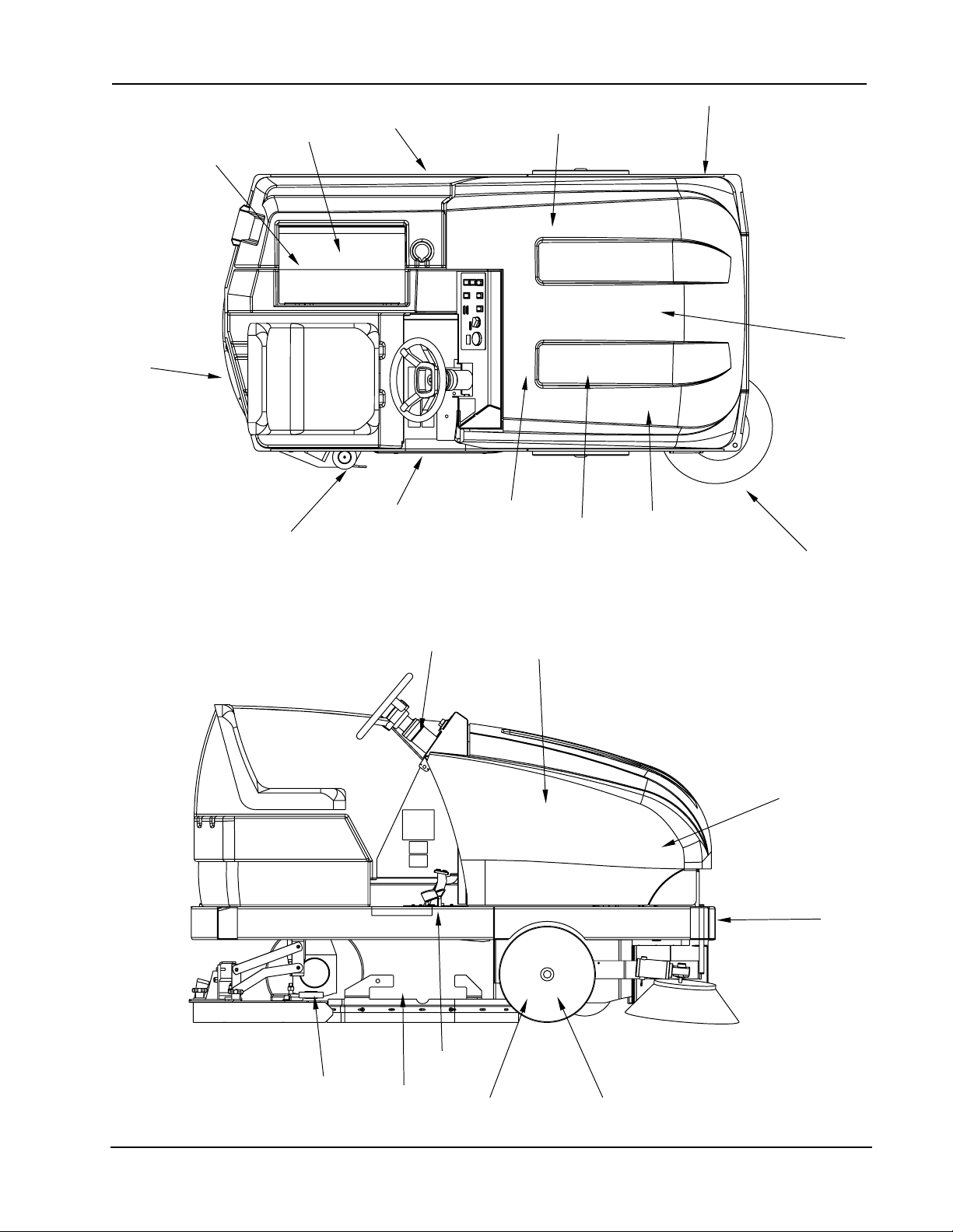
Page 6

INSTRUMENTS AND CONTROLS
Main/Side Broom Switch Key Switch
(activates immediately when lowered) Rectangular Hour Meter
Headlight/T aillight Switch (option) Battery Rollout
Squeegee Switch Recovery High Light
3 Position Scrub Deck Switch Dust Control Switch(with certain models)
Horn Button Solution Low Light
Solution Control Coolant T emperature Light
Hopper Up/Down Filter Shaker Switch
SCRUBBING SYSTEM
Brush Size-46” (116.84 cm) - Three (3) 16” (40.6cm) Diameter
Brush Size-40” (101.4 cm) - T wo (2) 20” (51cm) Diameter
Brush Drive Lift - Electric Actuator
Scrub Load
40” scrub p ath )(116.84 cm) - From 90 lbs. to 140 lbs. per brush (Battery)
46” scrub path)(101.4 cm) - From 90 lbs. to 140 lbs. per brush (Battery)
SQUEEGEE
Rear - Accu-Trac™ 46 in(1 16.8 cm) Swing, break away ,
Side - 26 in (66 cm) Easy Change
SPECIFICATIONS
w/no tool squeegee replacement
T ANKS
Solution T ank - 55 Gallons (208 liter)Polyethylene
Recovery T ank - 55 Gallons (208liter)Polyethylene
Solution Metering - V ariable to 3.0 GPM (1 1.4 lpm)
Drain Hose - 48 in (122 cm) No Plug required
Clean Out Port - 5.7 in (14.5 cm) heavy debris
HOPPER
Capacity - 2.5 cu.ft.(71liter)
DUMP AND LIFT
Dump Height - 14 in (35.6 cm.)
SYSTEM FLUID CAP ACITIES
Hydraulic System (Battery) - 4.7 Gallons (17.79 Liters)
OPTIONAL EQUIPMENT
Back-Up Alarm Headlight/T aillights
Push Pull Light Switch (Work Light) Strobe Light (Red or Amber)
ESP System w/o Detergent Provisions Overhead Guard
Pad Drivers Arm Rest
Spray and Vac Wand Option Fire Extinguisher
Linatex Squeegee Squeegee Wand
720 Amp Hour Battery 510 Amp Hour Battery
AMERICAN-LINCOLN TECHNOLOGY 1 - 5
SMART 2000
Page 7
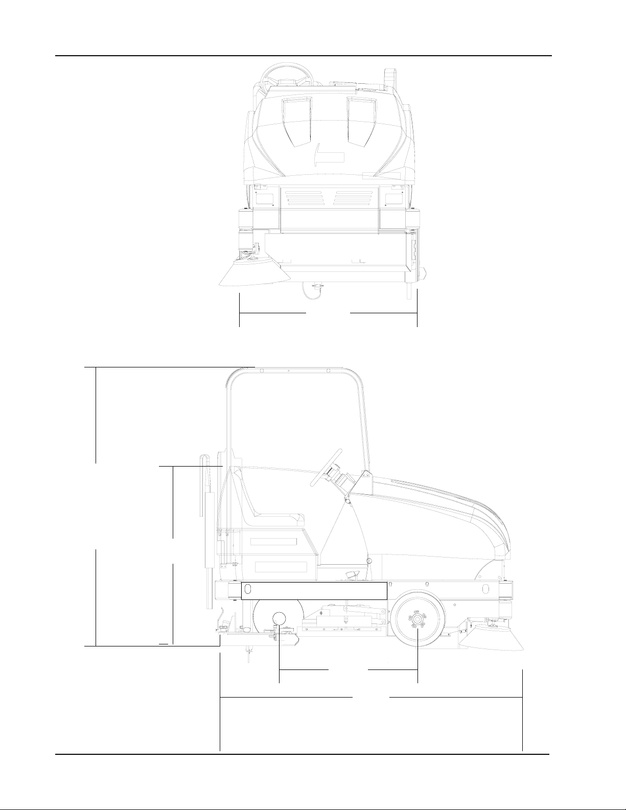
MACHINE DIMENSIONS
46"
(116.8 cm)
79”
(200.6 cm)
52"
(132 cm)
37.6"
c1961/0002
(95.5 cm)
87”
(221 cm)
1 - 6 AMERICAN-LINCOLN TECHNOLOGY
SMART 2000
Page 8
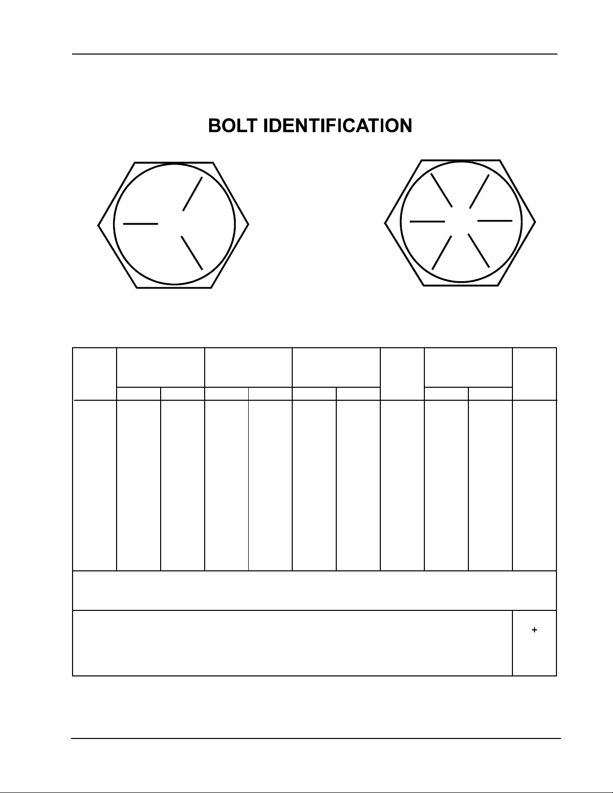
STANDARD HARDWARE & TORQUE VALUES
SAE - Grade 5
C
14
27
39
86
15
28
44
68
98
135
239
387
579
Grade
5
Plated
Grade
8
Plated
FFF
15
28
43
108
17
31
49
76
110
153
267
-
-
C
-
-
-
130
22
40
63
95
138
191
338
545
818
-
-
-
151
24
44
70
108
155
216
378
-
-
410H
Stainless
C
18
33
47
114
19
34
55
85
-
-
-
-
-
20
35
54
132
22
39
62
95
-
-
-
-
-
Screw
Size
*6
*8
*10
*1/4
5/16
3/8
7/16
1/2
9/16
5/8
3/4
7/8
1
C = Coarse Thread
F = Fine Thread
* = Torque values for #6 through 1/4 are lb./in. All others are lb./ft.
Brass
5
9
13
32
6
10
16
-
-
-
-
-
-
SAE - Grade 8
Type
F&T
&BT
C
20
37
49
120
-
-
-
-
-
-
-
-
-
F
23
41
64
156
-
-
-
-
-
-
-
-
-
Type
B, AB
21
34
49
120
-
-
-
-
-
-
-
-
-
NOTE
Decrease the torque by 20% when using thread lubricant
The torque tolerance is ± on torque values.
C2000/9905
AMERICAN-LINCOLN TECHNOLOGY 1 - 7
SMART 2000
Page 9

HYDRAULIC TORQUE REQUIREMENTS
HYDRAULIC TORQUE REQUIREMENTS
Refer to the following chart for torque values on all hydraulic hoses and fittings.
Nominal O-Ring Face Seal End SAE O-Ring Boss End
SAE Thread Swivel Thread Str. Fitting
Dash Size Nut Size or Locknut
Size Inch Torque Inch Torque
LB-FT LB-FT
-3 * * 3/8-24 8-10
-4 9/16-18 10-12 7-16-20 14-16
-5 * * 1/2-20 18-20
-6 11/16-16 18-20 9/16-18 24-25
-8 13/16-16 32-35 3/4-16 50-60
-10 1-14 46-50 7/8-14 72-80
-12 1 3/16-12 65-70 1 1/16-12 125-135
-14 1 3/16-12 65-70 1 3/16-12 160-180
-16 1 7-16-12 92-100 1 5/16-12 200-220
-20 1 11/16-12 125-140 1 5/8-12 210-280
-24 2-12 150-165 1 7/8-12 270-360
* O-Ring face seal type end not defined for this tube size.
NOTE
Parts must be lightly oiled with hydraulic fluid.
C-2002
1 - 8 AMERICAN-LINCOLN TECHNOLOGY
SMART 2000
Page 10
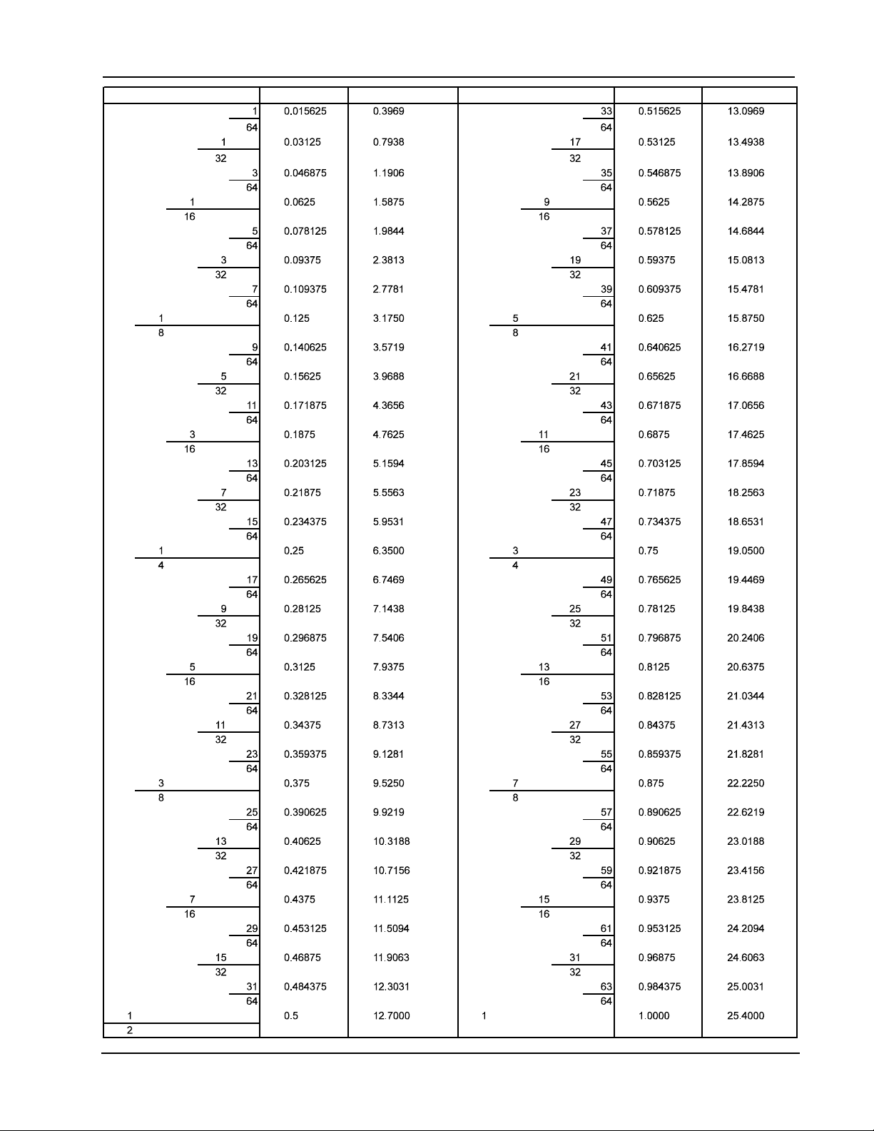
DECIMAL - METRIC CONVERSION TABLE
FRACTION FRACTION
DECIMAL DECIMAL
MILLIMETER MILLIMETER
C-2001/9907
AMERICAN-LINCOLN TECHNOLOGY 1 - 9
SMART 2000
Page 11
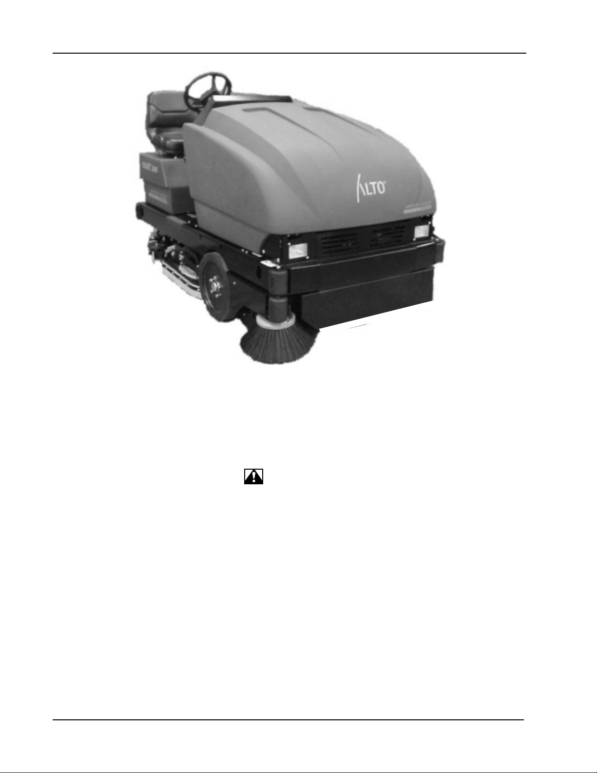
MACHINE PREPARATION
Figure 1
YOUR SMART 2000 MACHINE HAS BEEN SHIPPED COMPLETE, BUT DO NOT A TTEMPT TO OPERA TE
WITHOUT FOLLOWING THESE INSTRUCTIONS.
PREP ARING THE MACHINE FOR OPERA TION (IC Engine Powered)
1. Connect and tighten battery cables.
2. Fill the tank with REGULAR GRADE gasoline. (Diesel fuel if equipped with diesel engine.)
WARNING
Never fill the tank while the engine is running. Always be sure the gasoline container and sweeper are electrically
connected before pouring gasoline. This can easily be done by providing an insulated wire (permanently attached
to container) with a battery clip on the other end.
3. Check engine crankcase oil level. Although properly lubricated at the factory, check before starting the
engine. No special break in oil is used and recommended number of operating hours before the initial oil
change is the same as normal. See Maintenance.
4. Check radiator coolant level. Permanent type antifreeze is added at the factory to provide protection to approximately -35°F (37°C). To retain this protection level, always add ½ part water to ½part
antifreeze.
5. Check oil level in the hydraulic reservoir located at the drivers side of the machine beside the engine. The
oil fill level should be halfway on sight glass. If oil is needed, add Standard, 30 weight, non-detergent motor
oil. Af ter the first 50 operating hours, service must be performed on your engine to ensure future high
performance and trouble free operation. See Maintenance.
1 - 10 AMERICAN-LINCOLN TECHNOLOGY
SMART 2000
Page 12

MACHINE PREPARATION - BATTERY
NOTE
After the first 35 operating hours, service must be performed on your engine to ensure future high performance
and trouble free operation. See Maintenance.
BA TTERY POWERED MACHINES
*Uncrate the machine and carefully remove from skid to prevent damage.
*The SMART 2000 machines that are shipped without batteries have the (+) positive drive motor lead
disconnected.
*Open the battery compartment and connect the (+) positive motor lead to the top terminal post
(the wire “P” is also attached to it). Tighten the terminal nut.
*Install the scrub brushes.
*Check the oil level in the hydraulic reservoir
*Install batteries as follows (if not included):
1. Turn the key to the “OFF” position.
2. Raise the Front Cover to the open position.
3. Use a battery lifting device with a 2500 lbs. (1 150 Kg) cap acity hoist to lift the battery. Set up the battery
tray in the center position. Make sure the size of the battery fits into the tray prior to installation
(20.25W x 38.50 x 31.00 L).
4. Using the lifting device, lower the 36 volt battery into the battery tray directly in front of the
driver’s compartment. Orient the cables & plug them in as required.
5. Plug the polarized connector from the battery into the 36 volt plug provided.
WARNING
Hydrogen gas is formed during the charging operation and is explosive! Only charge batteries in a well ventilated
area with the lid open. Avoid any open flame or electrical sparks. Pulling out the charger plug with the timer on
will cause an arc and must be avoided.
AMERICAN-LINCOLN TECHNOLOGY 1 - 11
SMART 2000
Page 13

SAFETY INSTRUCTIONS
THE FOLLOWING ST A TEMENTS ARE USED THROUGHOUT THIS MANUAL AS INDICA TED IN THEIR
DESCRIPTIONS:
DANGER
To warn of immediate hazards which will result in severe personal injury or death.
WARNING
To warn of hazards or unsafe practices which could result in severe personal injury or death.
CAUTION
T o warn of hazards or unsafe practices which could result in minor personal injury .
A TTENTION
T o warn of unsafe practices which could result in extensive equipment damage.
NOTE
To give import ant information or to warn of unsafe practices which could result in equipment damage.
WARNING
THE FOLLOWING INFORMATION SIGNALS POTENTIALL Y DANGEROUS CONDITIONS T O THE OPERATOR OR EQUIPMENT . READ THIS MANUAL CAREFULL Y . KNOW WHEN THESE CONDITIONS CAN EXIST . THEN, T AKE NECESSARY
STEPS TO TRAIN MACHINE OPERA TING PERSONNEL. FOR THE SAFE OPERATION OF THIS MACHINE, READ AND
UNDERST AND ALL WARNINGS, CAUTIONS AND NOTES.
WARNING
Machines can ignite flammable materials and vapors. Do not use with or near flammables such as gasoline, grain
dust, solvents, and thinners.
WARNING
Improper use of heavy machinery can cause personal injury .
WARNING
Operate only when lids, doors, and access panels are securely closed.
WARNING
Use care when reversing machine in confined area.
WARNING
When servicing the machine, disconnect the batteries first to prevent possible injury.
WARNING
When working on the machine, empty hopper, remove batteries, clear area of people and obstructions, use
additional people and proper procedures when lifting the machine.
WARNING
Always empty the hopper and disconnect the battery before doing maintenance.
WARNING
You must have training in the operation of this machine before using it. READ THE INSTRUCTION BOOK.
WARNING
Do not operate this machine unless it is completely assembled.
WARNING
Do not use this machine as a step or furniture.
WARNING
Stop and leave this machine on a level surface. When you stop the machine, put the power switch in the “OFF”
position and engage the Wheel Lock.
1 - 12 AMERICAN-LINCOLN TECHNOLOGY
SMART 2000
Page 14

SAFETY INSTRUCTIONS
WARNING
T o prevent injury and damage to the machine, do not lift the machine or move it to an edge of a st air or loading
dock.
WARNING
Lead acid batteries generate gases which can cause an explosion. Keep sparks and flames away from batteries.
NO SMOKING . Charge batteries only in areas with good ventilation.
WARNING
Always wear eye protection and protective clothing when working near batteries. Remove all jewelry . Do not put
tools or other metal objects across the battery terminals or across the tops of batteries.
WARNING
Maintenance and repairs must be done by authorized personnel only . Tighten all fasteners. Maint ain adjustment s
according to the specifications given in the service manual for the machine. Keep the electrical parts of the
machine dry. For storage, keep the machine in a building.
WARNING
Make sure all labels, decals, warnings, cautions and instructions are fastened to the machine. Purchase new
labels and decals from American-Lincoln T echnology .
WARNING
The operator must exhibit extreme caution when negotiating, turning, and traveling across grades or ramps. Start,
stop, change direction, travel and brake smoothly . Slow down when turning.
WARNING
Avoid uneven surfaces and loose materials. Watch for obstructions, especially overhead.
WARNING
Operate only from the designated operator’s position. Stay inside the body of the machine. Keep hands and feet
on the designated controls. Always operate in well lighted areas.
WARNING
Do not carry passengers on the machine. Set the Wheel Lock when leaving the machine. Chock (block) the
wheels if the machine is parked on a grade (ramp), or is being prepared for Maintenance.
WARNING
Never leave the operator’s compartment when the is engine running.
WARNING
Report damage or faulty operation immediately . Do not operate the machine until repairs have been completed.
Maintenance and repairs must be done by authorized
personnel only .
WARNING
To maint ain the stability of this machine in normal operation, the overhead guard, counterweight s, roller bumper
guards, or any similar equipment installed by the manufacturer as original equipment should never be removed. If
it becomes necessary to remove such equipment for repair or maintenance, this equipment must be reinstalled
before the machine is placed back into operation.
WARNING
Electrical hazard. Shocks can cause serious personal injury. Unplug the battery before cleaning or servicing. To
avoid possible injury or property damage, read the Operator’s Manual before servicing the machine. Maintenance
and repair must be done by authorized personnel.
WARNING
Disconnecting the battery connector with the key switch in the “I” position will cause sparks that could ignite
explosive hydrogen gas generated by the batteries. T o prevent serious injury or possible property damage, turn
Key Switch to “O” position before disconnecting the battery cable from the machine for charging or service.
AMERICAN-LINCOLN TECHNOLOGY 1 - 13
SMART 2000
Page 15

SAFETY INSTRUCTIONS
FOR SAFETY , OBSERVE THE FOLLOWING W ARNINGS. FAILURE TO COMPL Y MA Y CREA TE A SERIOUS RISK OF INJURY
TO YOURSELF AND OTHERS. THIS MACHINE SHOULD NOT BE USED IN HAZARDOUS LOCA TIONS INCLUDING AREAS
OF VOLA TILE DUST OR VAPOR CONCENTRA TIONS.
Operators must be trained and qualified to operate this machine. They must also understand the operator’s
manual before starting.
Use caution when mounting or dismounting the machine particularly on wet slippery
surfaces. Do not dump the hopper over an open pit or dock. Do not dump the hopper when positioned on a grade
(ramp). The machine must be level (horizontal).
1 - 14 AMERICAN-LINCOLN TECHNOLOGY
SMART 2000
Page 16
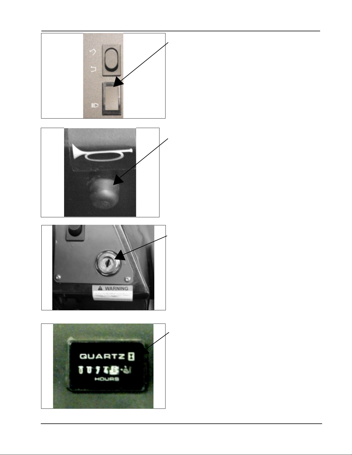
Figure 2
OPERA TION OF CONTROLS AND GAUGES
LIGHT SWITCH (See Figure 2)
The light switch is located above the horn button to the left
of the steering wheel. By pressing on the lower part of the
switch, it will work various light options that are available for
this machine, such as:
Headlights
Taillights
HORN BUTTON (See Figure 3)
The horn button is located to the left of the steering column
below the instrument panel. The horn button is always
active.
Figure 3
Figure 4
KEY SWITCH (See Figure 4)
The keyed ignition switch is located on the instrument panel
to the right of the broom lever.
The “OFF” position (O position) will shut off the engine. The
IGN/ON position (I position) provides power to all machine
systems and accessories. The “ST ART” position (one
position clockwise of I position) is momentary and provides
power to the starter motor.
NOTE
To reengage, the key must be returned to the “OFF” position.
HOUR METER (See Figure 5)
The hour meter is located on the instrument panel below the
fuel gauge (gas version), below the battery condition meter
(battery version). The meter is activated when the key
switch is placed in the ignition position. The meter
indicates the actual “run” time of the machine. The meter
can be used to determine when maintenance should be
done on the machine.
Figure 5
AMERICAN-LINCOLN TECHNOLOGY 1 - 15
SMART 2000
Page 17
OPERA TION OF CONTROLS AND GAUGES - Cont.
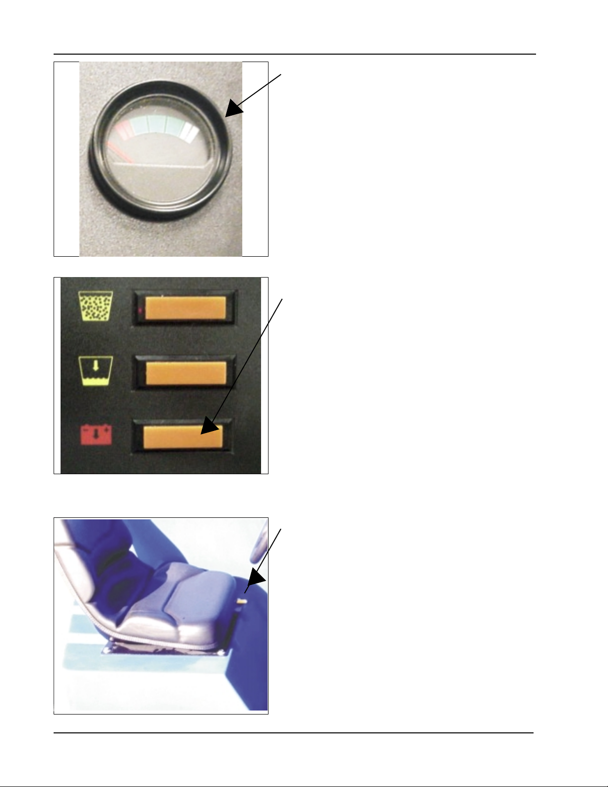
BA TTERY CONDITION METER (See Figure 6)
The battery condition meter is located on the right side of
the instrument panel. The condition meter indicates the
level of charge in the batteries (inspect underload). The
batteries are sufficiently charged when the needle stays in
the green area on the gauge while the machine is being
operated.
Charge the batteries when the needle drops into the red
zone while operating the machine. Do not operate the
machine if the needle stays in the red area.
Figure 6
BA TTERY CONDITION LIGHT (See Figure 7)
The meter shows the condition of the battery , while the
machine is running, under load. When the battery voltage
falls below 31-32 volts for longer than 2-3 seconds the low
voltage light will come on and the Brush/Water solenoids
will be shut off automatically. This is a permanent lockout
until the power is turned off to module. The low voltage
lock out can be reset almost immediately by turning off all
power to the module for 3-5 seconds. In a permanent low
battery condition, the machine can be functional only for
one minute periods an then only by turning the ignition off
and on.
Figure 7
SEA T POSITION ADJUSTMENT (See Figure 8)
The seat position adjustment lever is located on the front
of the seat to the left. The lever is spring loaded to the
“LOCK” position.
T o adjust the seat, push the lever to the “RIGHT” and
move the seat to the desired position. Then release the
lever to “LOCK” the seat into place.
Figure 8
1 - 16 AMERICAN-LINCOLN TECHNOLOGY
SMART 2000
Page 18
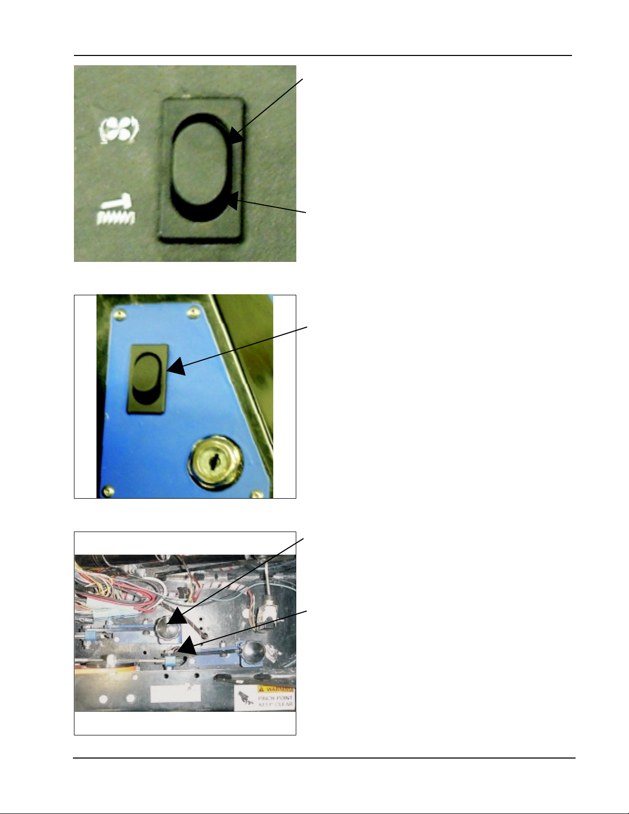
Figure 9
OPERA TION OF CONTROLS AND GAUGES - Cont.
FIL TER SHAKER SWITCH (See Figure 9)
The filter shaker switch is located on the top left corner of
the instrument panel . By pressing and holding in the
lower part of the switch, it will activate the filter shaker
motors for 20 to 30 seconds. Upon releasing the switch,
it will return to the off (middle) position.
The Impeller fan will stop when the filter shaker has been
activated. The filter shaker will only operate with the
hopper in the “DOWN” position.
DUST CONTROL SWITCH (See Figure 9)
The Dust Control Switch located on the top left corner of
the instrument panel. To turn on the dust control system
for “NORMAL” sweeping, press in the upper portion of the
switch. To turn off the dust control system for sweeping in
wet conditions, return the switch to the middle position
(wet sweep bypass). This will prevent the filter from being
damaged by water pickup while sweeping.
SIDE BROOM and MAIN BROOM SWITCH (See
Figure 10)
The Side and Main Broom Switch is located to the right of
the steering column. By pressing in the upper portion of
the switch, the side and main broom are raised and
turned off. To lower and turn on both brooms, press the
lower portion of the switch.
Figure 10
MAIN BROOM ADJUSTMENT (See Figure 1 1)
The main broom adjustment knob for changing the sweep
height to compensate for broom wear, is located in front
of the machine to the right of the filter. Turning the knob to
the left (counterclockwise) will lower the main broom.
SIDE BROOM ADJUSTMENT (See figure 1 1)
The side broom adjustment knob for changing the sweep
height to compensate for broom wear, is located in front
of the machine to the right of the filter. Turning the knob to
the left (counterclockwise) will lower the side broom.
Figure 1 1
AMERICAN-LINCOLN TECHNOLOGY 1 - 17
SMART 2000
Page 19
OPERATION OF CONTROLS AND GAUGES - Cont.
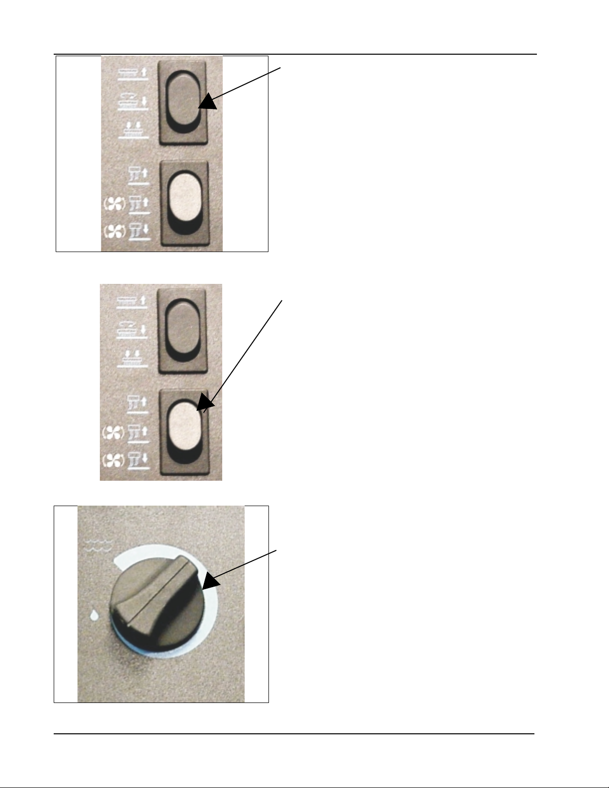
SCRUB DECK SWITCH (See Figure 12)
The scrub deck switch is located on the instrument panel
to the left of the solution control knob. Pressing in the
upperportion of th switch raises the scrub deck and turns
the brush. In the middle position, the scrub deck lowers
to the normal down position. Pressing the lower portion of
the switch lowers the scrub deck to the heavy down
position.
In the third position, Scrub Deck Heavy , additional
downward pressure is applied. This will help for extremely
dirty surfaces.
Lowering the scrub deck does not turn on the brushes. The
brushes turn on automatically when the machine moves in
Figure 12
SQUEEGEE SWITCH (See Figure 13)
The squeegee blade switch is located on the console to
the left of the steering wheel.Pressing the lower portion of
the switch will lower the squeegee and activate the
squeegee vacuum. Pressing the upper portion of the
switch will turn off the squeegee vacuum and raise the
squeegee.
NOTE
the forward or reverse direction.
Figure 13
Figure 14
In the middle position the switch will raise the squeegee.
In this position the vacuum remains on to allow vacuuming
the water that is left in the squeegee recovery hose. This
prevents water from dripping on the floor with the
squeegee “UP .”
If the squeegee is lowered and the direction of the
machine is reverse (activated by the FWD/REV pedal) the
squeegee will automatically raise.
Upon moving in the forward position, the squeegee wil
automatically return to the lowered position.
SOLUTIONS CONTROL KNOB (See Figure 14)
The solution control knob is located to the left hand side of
the steering wheel. Turning the knob counterclockwise will
increase the flow of solution and water. The farther the
solution control knob is turned the heavier the flow of water
and solution will be. Turning the knob counterclockwise
will decrease the flow of the water and solution. To turn
the water and solution off turn the knob all the way
counterclockwise.
NOTE
For best results, discontinue application of solution
10 feet before stopping or making a 90° or 180° turn.
1 - 18 AMERICAN-LINCOLN TECHNOLOGY
SMART 2000
Page 20
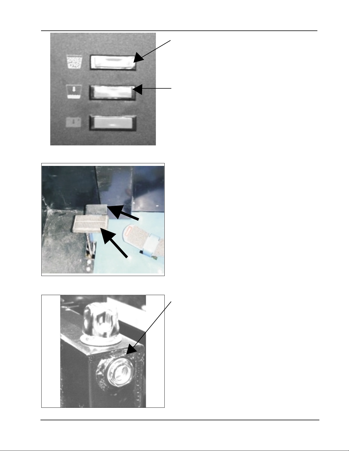
Figure 15
OPERA TION OF CONTROLS AND GAUGES - Cont.
RECOVERY HIGH LIGHT (See Figure 15)
The recovery high warning light will illuminate
approximately 5 minutes before the recovery tank is full,
giving ample time to complete the scrubbing cycle, before
the mechanical float shuts off the vacuum to the recovery
tank.
LOW SOLUTION LIGHT (See Figure 15)
The Low Solution Warning Light is located on the
console. The Solution Warning Light will illuminate when
the solution tank is empty , marking the end of the
scrubbing cycle.
P ARKING BRAKE (See Figure 16)
Never leave operator’s seat without engaging the parking
brake. The parking brake is located on the floor of the
machine left of the directional control pedal. To set the
parking brake, press down on the foot pedal (Item A) and
the press down the lock (Item B). To unlock the parking
B
brake, push down on the upper portion of the foor pedal
and release.
Figure 16
A
TURN SIGNAL - 4-Way (Option)
The turn signal option is located on the steering column
and works as automotive turn signals work, forward on
the lever for right and back on the lever for left. The 4-way
flasher will activate when the turn signal lever is pulled
out.
HYDRAULIC RESERVOIR LEVEL SIGHT GAUGE (See
Figure 17)
The sight gauge is located on the left side of the machine
under the front cover. The sight gauge is used to indicate
the level of fluid in the reservoir. The fluid level must be
visible in the sight gauge when the hopper is in the down
position.
Figure 17
AMERICAN-LINCOLN TECHNOLOGY 1 - 19
SMART 2000
Page 21
OPERA TION OF CONTROLS AND GAUGES - Cont.
ACCELERA TOR and DIRECTIONAL CONTROL PEDAL
- (See Figure 18)
The Accelerator and Directional Control Pedal is located
on the floor of the operator’s area. This pedal controls the
machine direction and travel speed.
1. Put foot pressure on the right side of the pedal. The
machine will move forward.
2. Increase the foot pressure on the right side of the
pedal to increase the forward speed.
3. Put foot pressure on the left side of the pedal. The
machine will move in reverse.
4. Increase the foot pressure on the left side of the pedal
to increase the reverse speed.
5. T o stop the machine, allow directional control pedal to
return to neutral (center position). Pedal will automatically return to neutral when foot pedal is released, or
put light foot pressure on the opposite end of the accelerator and directional control pedal. If the ma chine is moving forward, put light foot pressure on the
left side of the pedal. If the machine is moving in
reverse, put light foot pressure on the
Figure 18
right side of the pedal.
BACK-UP ALARM SWITCH (Option)
The back-up alarm is operated by a switch that is located
under the accelerator and directional control pedal
mounting plate. The alarm makes a loud audible noise
when the machine is being driven in reverse.
FIL TER P ANEL KNOB (See Figure 19)
The filter panel knob is used to hold the dust control filter
down. It is located in the hopper filter compartment and
will need to be removed periodically for cleaning or
replacement. Removal of the filter panel requires no
tools. The hopper cover must be opened to gain access
to the filter compartment. The panel filter is held in place
by a hinged frame and knob.
T o remove the panel filter , turn the knob counterclockwise
and lift the hinged frame. The panel filter can now be lifted
out and cleaned or replaced.
T o inst all the replacement panel filter , place a new filter in
the machine, lower the frame and twist the knob
clockwise to lock the filter in place.
Figure 19
1 - 20 AMERICAN-LINCOLN TECHNOLOGY
SMART 2000
Page 22
OPERATION OF CONTROLS AND GAUGES - Cont.
Figure 20
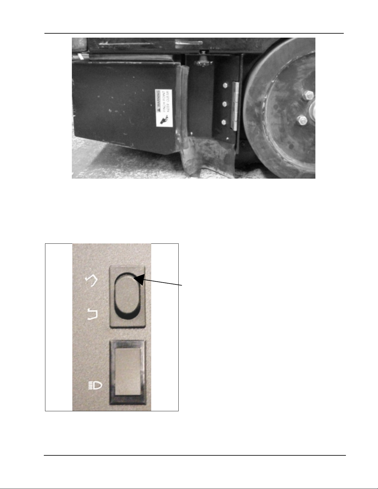
MAIN BROOM COMP ARTMENT DOOR (See Figure 20)
The main broom compartment door is located in front of the left side tire of the machine. The door provide
access to the main broom for service or inspection. The hopper must be raised to access.
Figure 21
WARNING
Engage hopper safety arm while accessing the main
broom.
HOPPER LIFT SWITCH (See Figure 21)
The hopper lift switch is located on the operator’s
compartment console. The switch controls the operation
of the hopper lift system.
T o raise the hopper for dumping, press and hold the
upper portion of the switch until the hopper reaches the
desired height or a ratcheting sound is heard, then
release.
NOTE
While the hopper is open a chime will ring letting the
operator know it is open. The chime will stop when the
hopper is completely closed.
T o close the hopper press in and hold the lower portion of
the switch until the hopper closes completely (chime wil
turn off) then release.
AMERICAN-LINCOLN TECHNOLOGY 1 - 21
SMART 2000
Page 23
ESP SYSTEM OPERATING INSTRUCTIONS
THE SCRUBBING SYSTEM - HOW IT WORKS
There are two scrubbing systems available for the SMART 2000 machine, the non-recycling or standard
scrubbing system and the recycling or ESP scrubbing system.
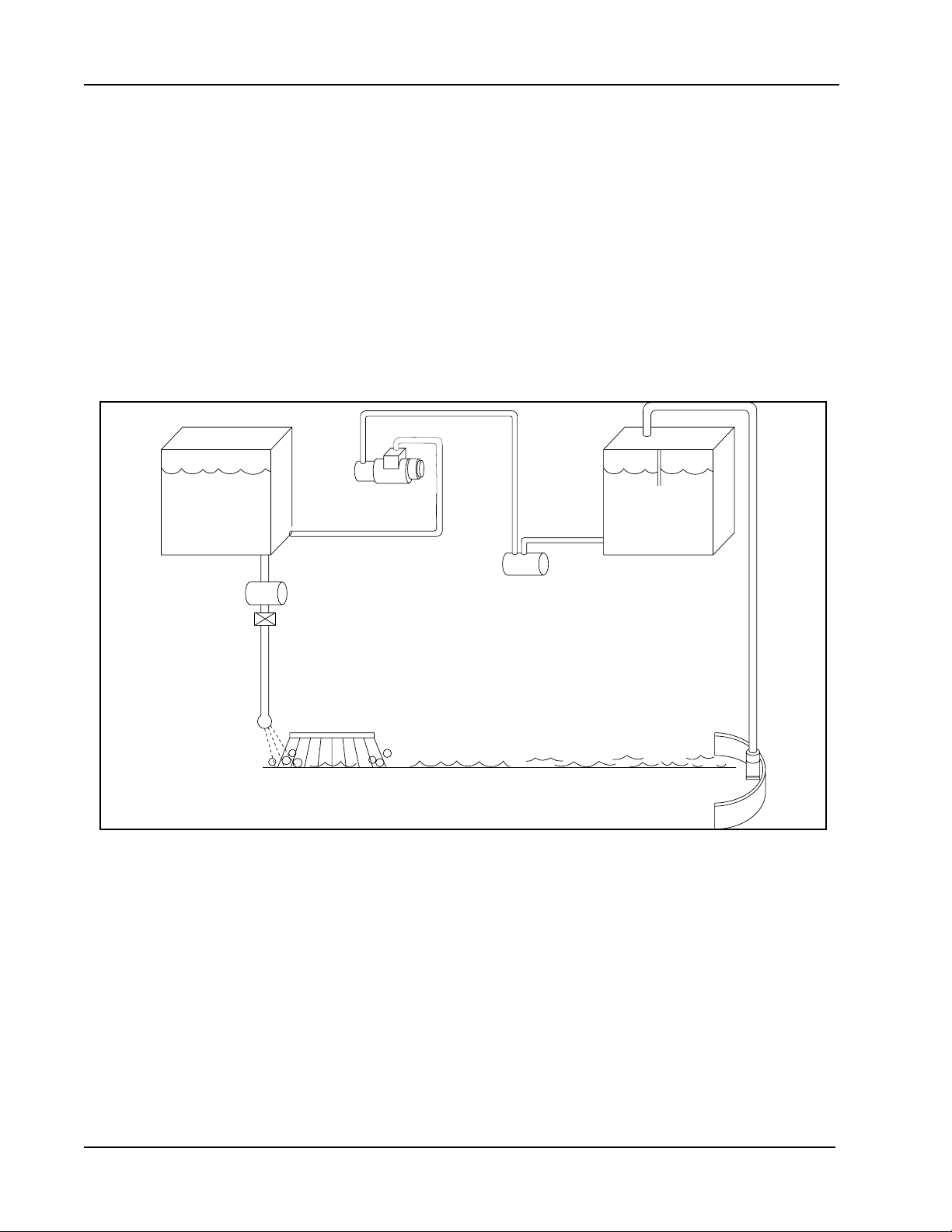
THE NON-RECYCLING OR ST ANDARD SCRUBBING SYSTEM - HOW IT WORKS
During the scrubbing process, detergent solution water from the solution tank is fed to the solution line.
There it is fed to the floor where three disc scrubbing brushes work to dislodge soil. Af ter scrubbing, the
dirty solution is vacuumed from the floor and discharged into the containment chamber in the forward
portion of the recovery tank, where a system of baffles helps to clarify the solution.
Sensors in each tank will indicate, by lights on the control panel, when the water in the solution tank is too
low or when the water in the recovery tank is too high.
THE ESP RECYCLING SYSTEM ON/OFF SWITCH (Option)
This switch turns the ESP recycling system on and off.
SOLUTION
TANK
P4796/0001
FILTER
SOLUTION
PUMP
FILTER
RECOVERY
TANK
FLOW VALVE
SEPARATOR
SCRUB
BRUSH
SQUEEGEE
FLOOR CONTACT
Figure 22
NOTE
The solution control lever must be on “FULL” for ESP operation.
THE RECOVERY OR ESP SYSTEM - HOW IT WORKS
During the scrubbing process, filtered water from the solution tank is fed to the solution line, where it combines
with detergent . This mixture is then fed to the floor where three disc scrubbing brushes work to dislodge soil.
After scrubbing, the dirty solution is vacuumed from the floor and discharged into the recovery tank. At intervals,
a float switch activates the recycling pump, which sends filtered solution from the recovery tank to the solution
tank.
1 - 22 AMERICAN-LINCOLN TECHNOLOGY
SMART 2000
Page 24

OPERATING INSTRUCTIONS
BEFORE ST ARTING THE MACHINE
1. Set parking brake.
2. Make sure all controls are in the “OFF” position.
3. Be sure the directional control pedal is in neutral.
4. Ensure the batteries have been fully charged and serviced (see battery service instructions).
NOTE
Before starting the engine, perform the pre-start checklist.
PRE-ST ART CHECKLIST
1 Clean engine air filter element.
2 Check hydraulic fluid level.
3 Check all systems for leaks.
4 Check brakes and controls for proper operation.
5 Check broom patterns.
6 Check to ensure that all covers, panels and access doors are securely closed.
NOTE
To prevent possible fire, never fill fuel t ank while the engine is running. Always be sure gasoline container and
machine are grounded before dispensing gas. This can be done by permanently attaching an insulated wire with a
battery clip on the end to the gasoline container .
ST ARTING BATTER Y MACHINES
St arting the battery powered models is accomplished by turning the key switch to the “I” (on) position. It is
important to note that the batteries should be fully charged and serviced prior to using the machine.
After turning off the machine, perform these post-operation checks.
POST-OPERA TION CHECKLIST
1. Clean the debris hopper.
2. Check sweeping brooms for wear or damage.
3. Check all flaps for wear, damage and adjustment.
4. Check all systems for leaks.
5. Charge and service motive power batteries.
6. Check squeegees for damage.
NOTE
AMERICAN-LINCOLN TECHNOLOGY 1 - 23
SMART 2000
Page 25

SERVICE CHART
SERVICE CHART
Check items for proper operation. If service is required, please contact an authorized American-Lincoln
T echnology distributor . For best performance, replace worn parts with genuine American-Lincoln Technology
parts.
EVERY eight (8) HOURS or DAILY check and clean/adjust if necessary:
1 Inspect panel filters for damage and clean them.
2 Inspect and clean hopper.
3 Inspect and clean recovery tank screens and filters.
4 Check hydraulic fluid level.
5 Check all flaps for wear or damage.
6 Check brooms for wear or damage, adjust as required.
7 Check brake pedal and parking brake.
8 Check hydraulic oil filter.
9 Check battery electrolyte level.
1 0 Check all fluid system components for leaks.
50 HOUR (WEEKL Y) MAINTENANCE CHECKLIST
11 Check solution tank (recycling or ESP system).
1 2 Check solution filter screen (recycling or ESP system).
13 Check recovery tank.
1 4 Check recovery tank screens and filters.
15 Inspect scrub brushes for wear or damage.
16 Inspect rear and side squeegees for wear or damage.
17 Check battery electrolyte level.
1 8 Check all hydraulic hoses for wear or cuts.
19 Rotate main brush (end over end).
20 Clean or replace panel filters.
21 Lubricate squeegee casters.
22 Clean throttle rod springs
100 HOUR MAINTENANCE CHECKLIST
23 Lubricate drive wheel, swivel wheel bearings, and steering rack guide (engine side above rear wheel).
24 Lubricate front wheel bearings.
25 Lubricate all moving joints.
2 6 Check brake shoes for wear and adjust accordingly .
2 7 Lubricate all bushings with anti-seize lubricant. The bushings are located on the steering,
scrub deck lift, and squeegee lift
250 HOUR MAINTENANCE CHECKLIST
28 Lubricate squeegee casters.
2 9 Clean solution tank and filter screen.
30 Replace hydraulic filter element.
31 Clean hydraulic reservoir.
1 - 24 AMERICAN-LINCOLN TECHNOLOGY
SMART 2000
Page 26
1,20
2
3,13,14
4,31
5,16
5,16
5,16
6
6,19
8,18
30,
9,17
10
11,12,29
21,28
21,28
23
27
27
26
24
25
C1960/0102
22
SERVICE CHART DIAGRAM
Figure 23
AMERICAN-LINCOLN TECHNOLOGY 1 - 25
SMART 2000
Page 27
HELPFUL HINTS FOR CLEANING OPERATION
SIDE AISLES
MAIN AISLE
P4134/0001
Do not turn the steering wheel sharply when the machine is in motion. The machine is very responsive to
movement of the steering wheel. Do not make sudden turns. Scrub in straight paths. Do not bump posts. Do
not scrape the sides of the machine.
1. Plan your sweeping and scrubbing in advance. Try to arrange long runs with minimum stopping and
starting. Sweep debris from narrow aisles out into main aisles ahead of time. Do an entire floor or
section at one time.
2. Pick up oversize debris before sweeping.
3. Allow a few inches of overlap of sweep and scrub paths. This will eliminate leaving dirty patches.
4. Do not turn steering wheel too sharply when the machine is in motion. The machine is very responsive
to movement of the steering wheel, so avoid sudden turns.
5. Try to follow as straight a path as possible. Avoid bumping into posts or scraping the sides of the
machine.
6. Always allow the machine to warm up before operating in cold temperatures.
7. Periodically turn the sweeping broom end-over-end to prevent the bristles from “setting” in one direction.
Replace the sweeping broom when the bristles are worn to 3 inch (8 cm) length. Replace disc brushes when
bristles are reduced to ½ inch (1.3 cm) in length. Replace squeegee rubbers when all usable edges have
become rounded with wear, impairing the wiping action.
SIDE AISLES
Figure 24
WARNING
NOTE
1 - 26 AMERICAN-LINCOLN TECHNOLOGY
SMART 2000
Page 28

SERVICE PRECAUTIONS
For safety , read and follow the service precautions below. Know the hazards associated with the equip
ment you are working on to prevent personal injury or damage to equipment.
For service assistance, consult you nearest American Lincoln T echnology Dealer . For best performance
replace worn parts with genuine American Lincoln Technology parts.
Refer all Maintenance and Service requirements to Qualified Maintenance Personnel.
WARNING
DO NOT attempt to service this machine until you have read and understand all Safety Warnings associated with
the equipment you are working on.
WARNING
Electrical repairs must be done by authorized personnel only . Consult your American-Lincoln Authorized Service
Person to do service procedures. Use only genuine American-Lincoln parts.
WARNING
Unexpected movement could cause injury. Always p ark on a level surface, turn key off, and engage p arking brake
before working on the machine.
WARNING
Maintenance and repairs must be done by authorized personnel only . Always empty the hopper and disconnect
the batteries before doing any maintenance. Keep all fasteners tight. Keep adjustments according to the specifi-
cations as shown in the Service Manual for this machine.
WARNING
Always wear eye protection and protective clothing when working near batteries. Do not put tools or other metal
objects across the tops of the batteries. NO SMOKING.
WARNING
The hopper could fall and cause serious injury. Always engage the hopper safety arm before working under the
hopper.
WARNING
Moving the fan and belt may cause injury . Stay clear of moving p art s.
WARNING
Pinch points may cause injury . St ay clear of moving p arts.
WARNING
T o maintain the stability of this machine in normal operation, the overhead guard, or any similar equipment
installed by the manufacturer as original equipment should not be removed. If it becomes necessary to remove
such equipment for repair or maintenance, this equipment must be reinstalled before the machine is placed back
in operation.
WARNING
T o prevent injury or engine damage, do not remove the radiator cap under any conditions while the engine is
running or when it is hot. To prevent burns from steam or scalding hot coolant being expelled from the radiator ,
use extreme care when removing the radiator cap. Wait until the engine has cooled.
AMERICAN-LINCOLN TECHNOLOGY 1 - 27
SMART 2000
Page 29
SERVICE INSTRUCTIONS
SWEEPING SYSTEM SERVICE
Figure 25
MAIN BROOM
T o prevent the broom from “setting” in one direction and to
provide the maximum life of the broom it is recommended
that the broom be turned end over end periodically .
ADJUSTING THE MAIN BROOM HEIGHT
When changing the sweep height adjustment it is
recommended that the knob be adjusted 1 turn at a time.
After adjustment, recheck the sweep pattern to determine if
further adjustment is necessary .
Turn the adjustment knob counterclockwise to IN-
CREASE the sweep pattern width.
Turn the adjustment knob clockwise to DECREASE the
sweep pattern width.
Figure 26
REPLACING THE MAIN BROOM
The Main Broom should be replaced when the bristles become
worn to less than 3". The main broom is held in place by the
right side broom door. This feature provides for easy removal
and installation of the main broom without the need for special
tools or equipment. Follow the instructions below for main broom
removal & replacement.
1. Park sweeper on a smooth level surface, engage park ing
brake, turn key switch to “O”, place the main/side broom
switch in the “SWEEP” position.
2. Open the main broom door.
3. Swing the broom drive idler hub out to clear the main
broom.
4. Remove the broom from the broom compartment.
5. Install the replacement broom. Pay special attention to
the slots on the broom, it may be necessary to rotate the
broom so the tabs on the drive hub align with the slots on
the broom.
6. Swing the idler hub to engage the main broom and close
the access door. Check the door latch for proper engage
ment when closed.
7. Check the Main Broom sweep pattern and adjust as
necessary .
1 - 28 AMERICAN-LINCOLN TECHNOLOGY
SMART 2000
Page 30
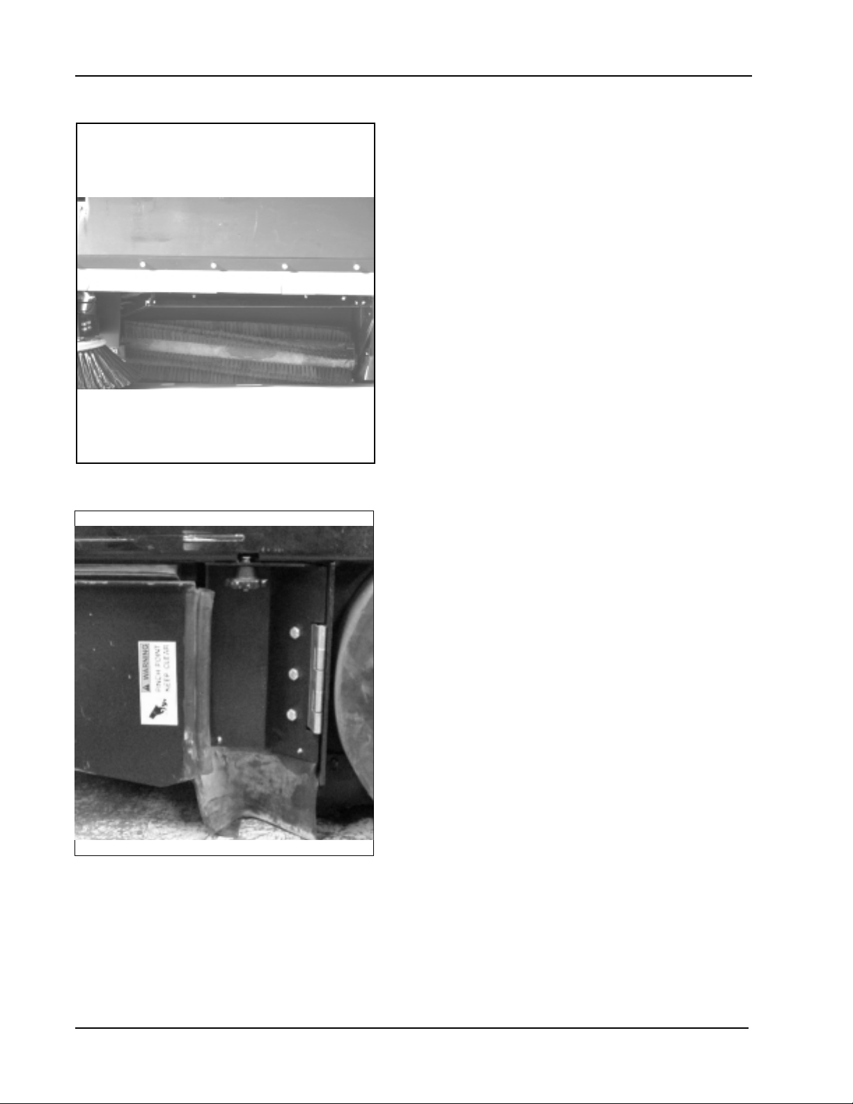
SIDE BROOMS SERVICE
Figure 27
SERVICE INSTRUCTIONS (Cont.)
SIDE BROOM
The Side Broom sweeping angle is not adjustable however
the height of the side brooms can be adjusted to
compensate for wear as the broom becomes worn from
use. Always check and adjust the sweep p attern after
changing the side broom.
ADJUSTING THE SIDE BROOM HEIGHT
Turn the side broom adjustment knob to change the side
broom sweep height. Recheck for proper sweep pattern
after adjustment.
Turn the adjustment knob counterclockwise to IN-
CREASE the sweep pattern width.
Turn the adjustment knob clockwise to DECREASE the
sweep pattern width.
Figure 28
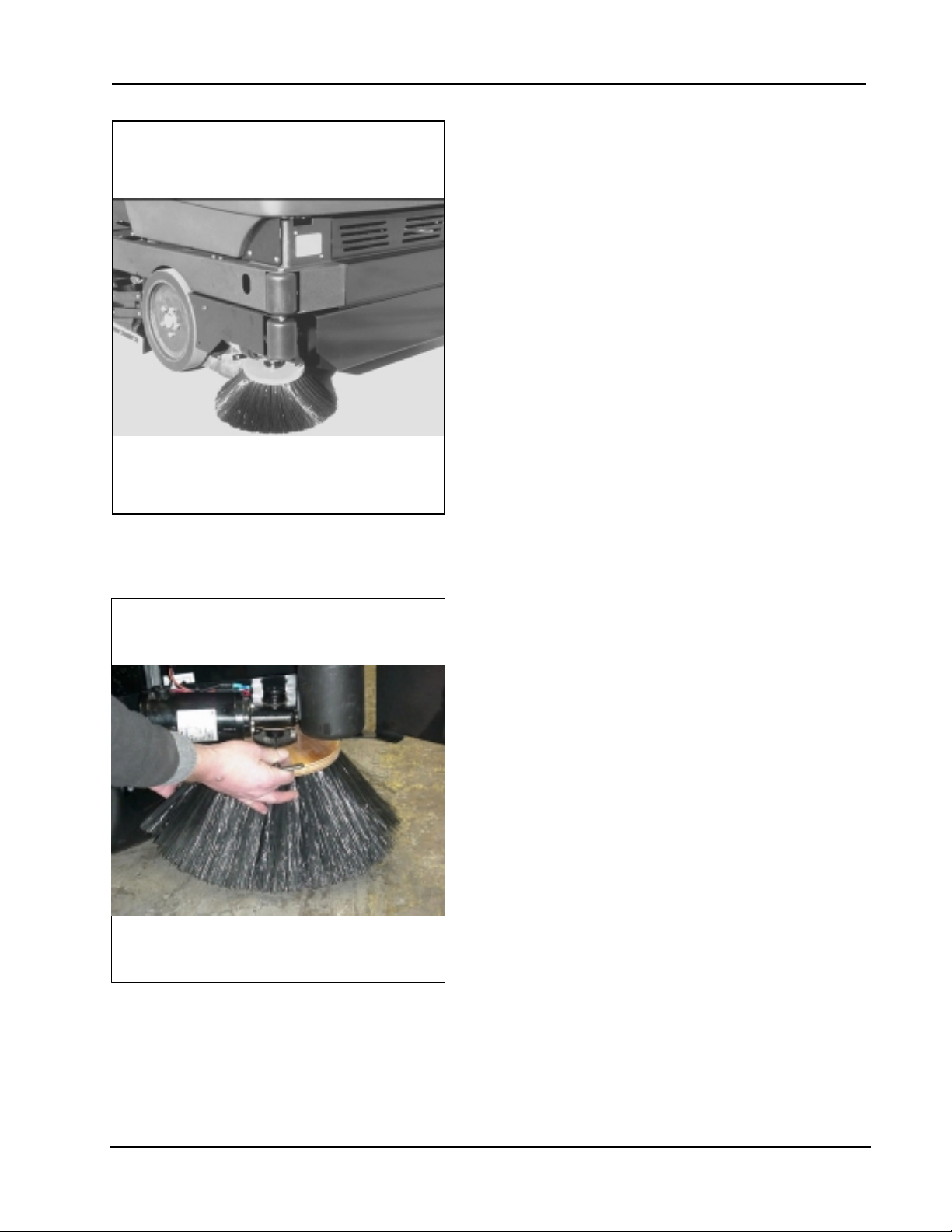
REPLACING THE SIDE BROOM
Change the side brooms when the bristles become worn to
less than 3 inches length.
1. Park the machine on a smooth level surface, turn key
switch to “O” Position and engage parking brake.
2. Place the side brooms switch in the “UP” position.
3. Remove the lock pin that holds the broom flange to the
motor shaft.
4. Disassemble the flange from the broom by removing the
screws that hold the flange to the broom.
5. Assemble the flange to the replacement broom and
fasten using the hardware removed.
6. Install the replacement broom on the shaft and insert
the lock pin.
AMERICAN-LINCOLN TECHNOLOGY 1 - 29
SMART 2000
Page 31

SERVICE INSTRUCTIONS (Cont.)
HOPPER SERVICE
REF
H34
Figure 29
HOPPER
The hopper houses the debris compartment, the dust control filter and the removable dust baffle. For
maximum performance and service life, keep the hopper clean and inspect the seals and flaps daily . Clean
the hopper prior to parking the sweeper at the end of the day . A clean hopper will make inspecting the flaps
and seals much easier and will prevent premature deterioration of hopper components. Do not leave the hopper
full of debris while in storage or when parked for extended periods of time
Figure 30
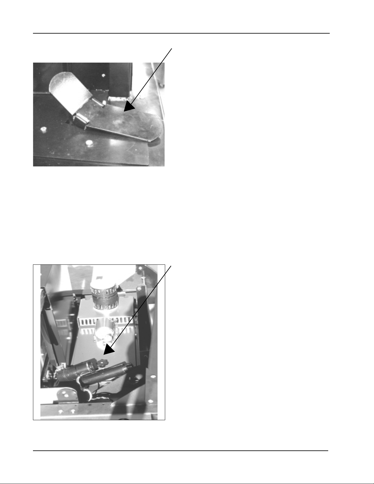
CLEANING THE HOPPER
Once the hopper has been emptied the insides of the hopper should be rinsed out with water.
AJDUSTING THE HOPPER SWITCH
With hopper fully closed and seated and bolt loose, rotate the bracket clockwise until the switch clicks.
Retighten bolt. (See Figure 30).
DUST CONTROL FIL TER
The dust control filter should be checked daily for damage and cleaned if necessary . A damaged filter must be
replaced to prevent damage to other dust control system components. Inspect the filter for tears in the filter
media or excessive dirt lodged in the pleats. A tear in the filter media will allow dirt to pass through the filter
and can be easily seen as a dirty patch on the top side on the filter . Cleaning of the filter is necessary when
the filter shaker fails to adequately clean the pleats.
CHECKING THE DUST CONTROL FIL TER
1. Park the machine on a smooth level surface, turn the key switch to the “O” position and engage the
parking brake.
2. Raise the hopper lid for access to the filter compartment.
3. Turn the filter latch, lift the filter frame and remove the filter .
4. Inspect the panel filter for tears and clean or replace if necessary .
5. Reinstall the filter , lower the filter frame and engage the filter latch.
6. Close the hopper cover.
CLEANING THE DUST CONTROL FIL TER
Clean the dust control filter when the shaker fails to adequately clear the filter. The filter can be cleaned with
compressed air not to exceed 100 PSI.
To clean the filter with compressed air, apply the compressed air to the top side of the panel to back flush the
lodged dirt from the filter pleats. Be careful to not damage the filter media while cleaning. The filter can be
cleaned with a solution of soap and water. If this cleaning method is used do not use the filter until it has
completely dried.
1 - 30 AMERICAN-LINCOLN TECHNOLOGY
SMART 2000
Page 32

HOPPER SERVICE - Cont.
SERVICE INSTRUCTIONS (Cont.)
Figure 31
REPLACING THE DUST CONTROL FIL TER
Change the filter panel when damage is evident.
1. Park the machine on a smooth level surface, turn the key switch to the “O” position and engage the parking
brake.
2. Open the hopper compartment cover to gain access to the filter compartment.
3. Turn the latch on the hinged frame counterclockwise and lift the frame .
4. Remove the filter panel.
5. Install replacement filter , lower the hinged frame and engage the latch.
6. Lower the filter compartment cover.
DUST FLAPS
The dust flaps are very important to sweeping and dust control and are susceptible to damage and should be
inspected daily and maintained in good condition.
CHECKING THE DUST FLAPS
The dust flaps are used on the wheel well, broom chamber and broom door . Inspect the flaps daily and replace
any flap that shows signs of wear or deterioration. All flap s should be replaced when worn or damaged to the
point that they can no longer perform their normal function. The adjustable flaps have slotted mounting holes to
facilitate adjustment.
ADJUSTING THE DUST FLAPS
Adjust the flaps so there is a 1/8" to 1/16" gap between the floor and the bottom edge of the flaps. The rear
flapadjustment is 1/16" (16 cm.) above the floor .
1. Park the machine on a smooth level surface and engage the parking brake.
2. Loosen the flap retaining screws and adjust the flap to clear the floor and leave a 1/16" to 1/8" gap.
3. Tighten flap retaining screws while holding flap in position.
4. Drive the machine on a smooth surface and recheck the flaps for proper floor clearance.
AMERICAN-LINCOLN TECHNOLOGY 1 - 31
SMART 2000
Page 33

SERVICE INSTRUCTIONS (Cont.)
P ARKING BRAKE SERVICE
C1539/0002
.10
Figure 32
Figure 33
P ARKING BRAKES
The parking brakes are located on the front wheels. They are operated by the brake pedal and the lock lever .
Check the parking brakes daily for proper operation and inspect the brake pads for wear every 100 hours of
operation.
ADJUSTING THE BRAKE PEDAL
Perform this adjustment to ensure proper pedal height and linkage operation. The brakes are properly adjusted
when the brakes hold the sweeper on an 8 degree ramp. The brakes need adjusted if the Pedal travels closer
than 1 inch to the floor of the operator’s compartment when the brakes are fully engaged.
WARNING
The hopper could fall and cause serious injury . Always engage the hopper safety arm before working under the
hopper.
WARNING
Always park on a level surface, chock tires and observe safety procedures when adjusting the brakes.
ADJUSTING THE P ARKING BRAKES
When adjusting the brake clevis, follow these steps.
1. Open cover.
2. Roll out battery on service cart
3. Remove Pin from clevis (U-Joint)
4. Adjust clevis clockwise to tighten brakes for maximum engagement.
5. With parking brake “off” rotate wheel with minimum drag (not completely free)
ADJUSTING THE FOOT THROTTLE SWITCH
With the foward/reverse pedal in the neutral position, the switches can be adjusted to .100” of face on the
forward/reverse pedal.
1 - 32 AMERICAN-LINCOLN TECHNOLOGY
SMART 2000
Page 34

GENERAL MACHINE MAINTENANCE
FILLING THE HYDRAULIC RESERVOIR (Figure 29)
1. Access to the hydraulic reservoir is located in the engine
compartment.
2. Open the hydraulic reservoir breather filter cap.
3. Remove any debris that is in the breather filter cap
screen.
4. Fill the reservoir until the fluid is at the “FULL” line
on the hydraulic fluid sight gauge. The sight gauge
is located on the center side of the hydraulic res
ervoir.
5. Close the hydraulic reservoir breather filter cap.
6. Close the engine compartment cover .
Figure 34
CLEANING THE HYDRAULIC SYSTEM
1. Put a drop cloth on the floor.
2. Drive the machine onto the drop cloth.
3. Set the parking brake.
4. Open the engine covers.
5. Put a container under the reservoir drain to catch the reservoir fluid. Pivot the reservoir out.
6. Remove the drain plug. The reservoir fluid will drain. Do not use the drained fluid to refill the
hydraulic reservoir. Dispose of the used fluid.
7. Flush the interior of the hydraulic reservoir with clean fluid.
8. Put the reservoir plug, removed in step six, back in the hydraulic tank drain and tighten it. A pipe
thread sealer is required on the plug.
9. Open the breather filter cap.
10. Fill the reservoir with new SAE 30W non detergent automotive transmission fluid. The capacity of the tank is
4.7 gal (17.79 liters). Fill to the “FULL” line on the hydraulic fluid sight gauge.
1 1. Close the breather filter cap. Rotate the reservoir into the engine compartment.
12. Replace the engine covers.
REPLACING THE RETURN FIL TER ELEMENT
1. Replace the return filter element after 250 hours of
machine run time.
2. Unscrew the fasteners from the filter assembly
cover and retain.
3. Remove the cover and the compression spring
and retain.
4. Discard the old filter element.
5. Position the new filter element inside the filter body .
6. Put the compression spring in position. Wipe the
cover magnet free of any metal filings or debris.
7. Place O-ring (moisten with clean hydraulic fluid)
and cover into position.
8. Reattach fasteners to the filter cover .
9. Clean any hydraulic reservoir fluid spills. The fluid
Figure 35
can damage painted surfaces of the machine.
AMERICAN-LINCOLN TECHNOLOGY 1 - 33
SMART 2000
Page 35

GENERAL MACHINE MAINTENANCE (Cont.)
REF ROD END
REF FRAME-
BRUSH DRIVE
Figure 36
REPLACING THE SCRUB BRUSH
1. Raise the scrub brush deck by pressing the “Scrub Brush” switch on the instrument panel.
2. Press the brush latches in to release the scrub brush.
3. Remove the old scrub brush.
4. Snap the new brush into place.
Figure 37
3.5"
ADJUSTING THE SCRUB DECK (See Figure 37)
Adjust the center of the rod end to 3.5” from the frame.
COVERS AND LATCHES
The covers have been designed to allow access, either by hinge or removal, to all areas of the machine. No
maintenance is required.
SOLUTION LOW WARNING LIGHT
The solution low warning light will illuminate when the solution tank is low. This part of the level control system
requires no maintenance. If the system fails to operate, consult the Electrical Troubleshooting Guide.
RECOVERY HIGH W ARNING LIGHT
The recovery high warning will illuminate approximately 5 minutes before loss of vacuum to the recovery tank.
This part of the level control system requires no maintenance, except for daily cleaning of the tank level switch.
If the system fails to operate, consult the Electrical Troubleshooting Guide.
SOLUTION CONTROL (Non-Recycling or Standard)
The solution control knob controls the amount of solution applied to the scrubbing brushes.
The solution control should shut off completely with the knob in the “off” position. If complete shut off does not
occur, the control valve should be adjusted.
SOLUTION CONTROL (Recycling or ESP System)
In the recycling mode, the solution control lever is also used to activate the detergent pump. If the detergent
pump fails to operate (engine running) when the solution control lever is moved into the low to high range, first
check the circuit by manually activating the switch. If the detergent pump does not operate at this time, a
further electrical or mechanical check is required (see Electrical Troubleshooting Guide or Detergent Pump
Troubleshooting).
1 - 34 AMERICAN-LINCOLN TECHNOLOGY
SMART 2000
Page 36

GENERAL MACHINE MAINTENANCE (Cont.)
RECYCLING PUMP ESP SYSTEM
The recycling pump is located under the seat. The pump is electric and except for daily cleaning of the pump
intake screens, it requires no regular maintenance.
RECYCLING PUMP STORAGE
Always drain pump for extended storage, especially when freezing temperatures may be encountered.
REAR SQUEEGEE
The squeegee will require service when the inner edges of the blades become round with wear, imp airing the
wiping action or water pickup. T o service the rear squeegee use the following step s:
1. Loosen the four aluminum knobs
2. Remove the squeegee tool and turn upside down to service the blades or caster wheels. The
squeegee blades are designed to flip over and use another unworn edge.
ADJUSTING THE REAR SQUEEGEE LIFT
1. Loosen nut (2-00-00641).
2. Turn screw (2-00-00087) either counterclockwise (to raise)
or clockwise (to lower) to adjust the position of the
squeegee lift. (The gap between the frame and the
squeegee lift should be .75”).
NOTE
Raising squeegee lift too far will cause the squeegee lift to hit the
EF SCREW
2-00-00087)
REF NUT
(2-00-00641)
C1980
frame and may cause damage.
Figure 38
To service the blades
1. Loosen the clamp bolts which clamp items 8 & 9 together .
2. Loosen far enough to slip the end clamp brackets off the squeegee tool. This will allow flipping the blades or
installing new blades.
3. Install blades so that the outer blade is 3/16” longer than the inner blades. This is achieved by assembling
the top edge of the blade against the squeegee tool weldment.
4. Reinstall the squeegee clamp band and tighten the clamp bolt.
SQUEEGEE CASTER WHEELS
There are 2 grease fittings on each caster wheel. The casters
should be greased each time the blades are serviced.
ADJUSTING CASTERS
Lower the squeegee on a flat surface, making sure the rear
squeegee blade is perpendicular to the surface. Adjust the
caster 3/16” above the flat surface. Lock the jam nuts.
Figure 39
AMERICAN-LINCOLN TECHNOLOGY 1 - 35
SMART 2000
Page 37

GENERAL MACHINE MAINTENANCE (Cont.)
Figure 40
EMPTYING THE RECOVERY T ANK (Figure 36)
Simply lower the drain hose, telescope out to a drain and let the recovery tank drain. The farther you telescope
the hose the faster the water will drain.
When finished draining recovery tank loosen both knobs on the recovery clean out door . The door will pivot on
the left knob, allowing room to let any debris to be sprayed out of the recovery tank with a water hose or
pressure washer.
1 - 36 AMERICAN-LINCOLN TECHNOLOGY
SMART 2000
Page 38

ABBREVIATIONS - SCREWS
PARTS LIST LEGEND
ADJ
ADJ.SP
BHM
BHS
CAPT.SL
CAPT.WG
FHM
FIL.HM
HHC
HHM
HIHD
HSHC
HSFHC
KNH
MHHC
PHM
RHD
RHM
RHW
SHC
SHTB
SQ
TB
THM
WELD
WG
= Adjusting Screw
= Adjusting Plunger Screw
= Binding Head Machine Screw
= Button Head Socket Screw
= Captivated Slotted Screw
= Captivated Wing Screw
= Flat Head Machine Screw
= Filister Head Machine Screw
= Hexagon Head Cap Screw
= Hexagon Head Machine Screw
= 1/2 High Head Screw
= Hexagonal Socket Head Cap Screw
= Hexagonal Socket Flat Head Cap Screw
= Knurled Head Screw
= Metric Hexagon Head Cap Screw
= Pan Head Machine Screw
= Round Head Drive Screw
= Round Head Machine Screw
= Round Head Wood Screw
= Shiny Crown Cap Screw
= Shoulder Thumb Screw
= Square Head Screw
= Thumb Screw
= Truss Head Machine Screw
= Weld Stud
= Wing Screw
ABBREVIATIONS - SETSCREWS
HS
S
SH
-KCP
-CP
-OP
-FDP
-HDP
-FP
-COP
C-2004
AMERICAN-LINCOLN TECHNOLOGY 1 - 37
SMART 2000
= Hexagonal Socket Setscrew
= Slotted Setscrew
= Square Head Setscrew
= Knurled Cup Point Setscrew
= Cup Point Setscrew
= Oval Point Setscrew
= Full Dog Point Setscrew
= Half Dog Point Setscrew
= Flat Point Setscrew
= Cone Point Setscrew
Figure 36
Page 39

HARDWARE LEGEND
Key No. Part Number Description
H1 2-00-05060 Screw, #6-32 x 1.250 RHM
H2 2-00-00455 Flat Washer, .375 x .156 x .047
H3 2-00-01499 Lock Washer, #6 Med. Helical Spring
H4 2-00-00624 Nut, #6-32 Hex
H5 2-00-00645 Nut, Hex Fiber Insert #6-32
H6 2-00-00049 Scr ew, # 10-24 x .500 RHM
H7 2-00-00056 Scr ew, # 10-24 x .750 RHM
H8 2-00-00039 Screw, 10-24 x 1.000 RHM
H9 2-00-00426 Flat Washer, .500 x .219 x .063
H10 2-00-00519 Lock Washer, # 10 Med HS
H11 2-00-00605 Nut, Hex MS # 10-24 x .375 x .125
H12 2-00-01246 Nut, Hex Fiber Insert #10-24
H13 2-00-00054 Screw, 1/4-20 x .500 RHM
H14 2-00-00219 Screw, 1/4-20 x .500 HHC
H15 2-00-00221 Screw, 1/4-20 x .750 HHC
H16 2-00-03051 Screw, 1/4-20 x .750 HSHC
H17 2-00-00205 Screw, 1/4-20 x 1.000 HHC
H18 2-00-00060 Screw, 1/4-20 x 1.250 RHM
H19 2-00-02587 Screw, 1/4-20 x 1.250 HHC
H20 2-00-00203 Screw, 1/4-20 x 1.500 HHC
H21 2-00-01769 Screw, 1/4-20 x 1.750 HHC
H22 2-00-02589 Screw, 1/4-20 x 2.000 HHC
H23 2-00-01980 Screw, 1/4-20 x 2.500 HHC
H24 2-00-00220 Screw, 1/4-20 x .625 HHC
H25 2-00-00594 Nut, Hex 1/4-20 x .437 x .218
H26 2-00-00641 Nut, 1/4-20 Insert Fiber
H27 2-00-03702 Washer, .625 x .281 x .063
H28 2-00-04685 Screw, 1/4-20 x .750 HHC
H29 2-00-04966 Screw, 1/4-20 x 1.500 HHM
H30 2-00-04687 Lock Washer, Helical Spring 1/4 Med.
H31 2-00-04695 Screw, # 10-32 x .630 RHM
H32 2-00-04688 Nut, 1/4-20 Hex.
H33 2-00-00224 Screw, 5/16-18 x .500 HHC
H34 2-00-00208 Screw, 5/16-18 x .750 HHC
H35 2-00-02708 Screw, 5/16-18 x 1.000 HHM
H36 2-00-00196 Carriage Bolt, 5/16-18 x 1.000
H37 2-00-00207 Screw, 5/16-18 x 1.250 HHC
H38 2-00-00225 Screw, 5/16-18 x 1.500 HHC
H39 2-00-00218 Screw, 5/16-18 x 2.000 HHC
H40 2-00-01770 Screw, 5/16-18 x 2.750 HHC
H41 2-00-02597 Screw, 5/16-18 x 3.250 HHC
H42 2-00-02655 Screw, 5/16-18 x 4.500 HHC
H43 2-00-00409 Flat Washer, .687 x .344 x .062
H44 2-00-00530 Lock Washer, 5/16 HS Med.
H45 2-00-00585 Nut, Hex. 5/16-18 x .500 x .265
H46 2-00-00644 Nut, 5/16-18, Insert Fiber
H47 2-00-00232 Screw, 3/8-16 x .750 HHC
H48 2-00-00233 Screw, 3/8-16 x 1.000 HHC
H49 2-00-00209 Screw, 3/8-16 x 1.250 HHC
H50 2-00-00234 Screw, 3/8-16 x 1.500 HHC
H51 2-00-00216 Screw, 3/8-16 x 2.000 HHC
H52 2-00-00402 Flat Washer, .750 x .390 x .094
H53 2-00-02310 Lock Washer, Helical Spring 3/8 Med.
H54 2-00-02360 Nut, 3/8-16 Hex.
H55 2-00-00643 Nut, 3/8-16 Stop
H56 2-00-00239 Screw, 1/2-13 x 1.000 HHC
H57 2-00-00240 Screw, 1/2-13 x 1.250 HHC
H58 2-00-00241 Screw, 1/2-13 x 1.750 HHC
H59 2-00-00242 Screw, 1/2-13 x 2.250 HHC
1 - 38 AMERICAN-LINCOLN TECHNOLOGY
SMART 2000
Page 40

HARDWARE LEGEND
Key No. Part Number Description
H60 2-00-02682 Screw, 1/2-13 x 2.750 HHC
H61 2-00-02616 Screw, 1/2-13 x 3.000 HHC
H62 2-00-00405 Flat Washer, 1.063 x .531 x .094
H63 2-00-02312 Lock Washer, 1/2 HS Med.
H64 2-00-00596 Nut, Hex. 1/2-13 x .750 x .437
H65 2-00-04936 Nut, 1/2-13 Fiber Lock
H66 2-00-02689 Screw, 1/2-20 x 1.000 HHC
H67 2-00-00614 Nut, Hex 1/2-20
H68 2-00-00640 Nut, Hex Fiber Insert 1/2-20
H69 2-00-01255 Screw, 5/16-18 x .875 HHC
H70 2-00-05254 Screw, 3/4-10 x 2.250 HHC
H71 2-00-05255 Nut, 3/4-10 Nylon Lock
H72 2-00-00518 Lock Washer, Helical Spring
H73 2-00-00247 Screw, 1/2-13 x 2.500 HHC
H74 2-00-03170 Flat Washer, 1.500 x .750 x .125
H75 2-00-00618 Nut, Hex Jam 3/8-16
H76 2-00-00632 Nut, Fiber Insert 3/8-24 Steel
H77 2-00-00484 Flat Washer, .625 x .375 x .046
H78 2-00-05187 Carriage Bolt, 3/8-16 x 1.250
H79 2-00-01676 Flat Washer, 1.062 x .265 x .062'
H80 2-00-02196 Carriage Bolt, 1/4-20 x 1.000 RHM
H81 2-00-05276 Screw, 3/8-16 x 5.500
H82 2-00-00505 Lock Washer, 3/8 Int. Tooth
H83 2-00-04877 Screw, 1/4-20 x 1.000 BHS
H84 2-00-00228 Screw, 5/16-18 x 2.250 HHC
H85 2-00-00650 Nut, Cap 3/8-16 Low Crown
H86 2-00-03575 Carriage Bolt, 1/4-20 x .750
H87 2-00-00263 Set Screw, 1/4-20 x .250 HSKCP
H88 2-00-05258 Screw, #8-325 x .750 BHS
H89 2-00-01372 Nut, Fiber Insert #8-32 Steel
H90 2-00-03569 Carriage Bolt, 5/16-18 x .750
H91 2-00-05279 Screw, M6 x 1.0 x 20 mm MHHC
H92 2-00-04801 Flat Washer, .875 x .375 x .125
H93 2-00-00222 Screw, 1/4-20 x 1.250 HHM
H94 2-00-00410 Flat Washer, .875 x .375 x .060
H95 2-00-03382 Spring Washer, .875 x .500 x .015
H96 2-00-02605 Screw, 3/8-16 x 4.500 HHC, Cadium Plated
H97 2-00-04677 Screw, 1/4-20 x .750 HSC
H98 2-00-05277 Screw, 1/2-13 x .750 HSHC
H99 2-00-02810 Screw. 1/4-20 x 1.000 FHM
H100 2-00-03062 Screw, #10-24 x .625 THM
H101 2-00-04897 Screw, #10-24 x 1.250 THM
H102 2-00-04795 Screw, #10-24 x .750 BHS
H103 2-00-00089 Screw, 10-24 x 1.500 RHM
H104 2-00-03541 Screw, 1/4-20 x 1.500 FHSCH
H105 2-00-05260 Nut, Jam #8-32
H106 2-00-04886 Screw, 3/8-16 x .500 HSHC
H107 2-00-04887 Screw, Main Broom Control
H108 2-00-04888 Washer, Main Broom Control
H109 2-00-00522 Lock Washer, 3/4 Helical Spring
H110 2-00-03039 Screw, 1/4-20 x .625 HSHC
H111 2-00-03296 Screw, 3/8-16 x 4.000 HHC
H112 2-00-02603 Screw, 3/8-16 x 3.500 HHC
H113 2-00-03333 Screw, 3/8-16 x 3.750 HHC
H114 2-00-00633 Nut, Fiber 1/4-28
H115 2-00-03063 Screw, #10-24 x .750 THM
H116 2-00-01951 Carriage Bolt, 1/4-20 x 1.250
H117 2-00-05067 Flat Washer, 1.750 x .531 x .100
H118 2-00-02618 Screw, 1/2-13 x 3.500 HHC
H119 2-00-05005 Screw, M10 x 1.500 30 mm MHHC
AMERICAN-LINCOLN TECHNOLOGY 1 - 39
SMART 2000
Page 41

HARDWARE LEGEND
Key No. Part Number Description
H120 2-00-03829 Lock Washer, 3/8 Bolt
H121 2-00-00090 Screw, #8-32 x 1.500 RHM
H122 2-00-05216 Screw, 1/4-20 x 5.000 HHC
H123 2-00-00204 Screw, 1/4-20 x 1.500 HHC
H124 2-00-02296 Lock Washer, #10 Ext. Shakeproof
H125 2-00-00418 Flat Washer, .984 x .627 x .063
H126 2-00-03466 Screw, #10-16 x .500
H127 2-00-03522 Washer, 5/16 x 1.250 x .050
H128 2-00-04681 Carriage Bolt, 5/16-18 x 1.250
H129 2-00-02311 Lock Washer, 4.38 Split
H130 2-00-03334 Screw, .44-20 x 1.000 HHC
H131 2-00-03855 Carriage Bolt, 3/8-16 x 1.000
H132 2-00-00503 Lock Washer, 1/4 Ext.
H133 2-00-00006 Screw, #10-24 x .675 FHM
H134 2-00-03032 Screw, 3/8-16 x .750 FHS
H135 2-00-05298 Flat Washer, .344 x 2.000 x .062
H136 2-00-03940 Screw, #10-24 x .500 T/C HH
H137 2-00-05299 Screw, #10-24 x 1.250 HSHC
H138 2-00-00504 Lock Washer, Int.
H139 2-00-00611 Nut, Hex Jam, 3/8-24
H140 2-00-00447 Flat Washer, 1.250 x .280 x .090
H141 2-00-00501 Lock Washer, Int.
H142 2-00-05244 Carriage Bolt, 1/2-13 x 2.000
H143 2-00-00432 Flat Washer, 1.13 x .770 x .063
H144 2-00-02303 Lock Washer, Int.
H145 2-00-04180 Setscrew, 1/4-20 x .500
H146 2-00-00420 Flat Washer, 1.000 x .516 x .063
H147 2-00-00642 Nut, Fiber Insert 5/18-18
H148 2-00-01778 Screw, 1/2-13 x 2.000 HHC
H149 2-00-01803 Washer, 1.063 x .031 x .063
H150 2-00-00211 Screw, 5/16-18 x 1.750 HHC
H151 2-00-00213 Screw, 5/16-18 x .625 HHC
H152 2-00-01562 Carriage Bolt, 5/16-18 x 2.250
H153 2-00-03266 Washer
H154 2-00-04363 Screw, M8-1.250 x .750
H155 2-00-05044 Lock Washer, M14 Split
H156 2-00-05079 Screw, M14 x 1.500 x 25 mm HHC
H157 2-00-00217 Screw, 5/16-18 x 2.000 HHC
H158 2-00-05306 Screw, M14 x 35 mm HHC
H159 2-00-00512 Lock Washer
H160 2-00-00441 Flat Washer, .438 x .200 x .036
H161 2-00-00153 Screw, #8-24 x .875 OHM
H162 2-00-03961 Screw, 5/16-24 x 1.000 HHC
H163 2-00-03570 Carriage Bolt, 3/8-16 x .750
H164 2-00-00107 Screw, 10-24 x 4.50 RD. HD.
H165 2-00-00589 Nut, Hex Jam, .25-20
H166 2-00-00066 Screw, 6-32 x .50 RHM
H167 2-00-04312 Screw, 10-24 x .625 T/C Hex HD.
H168 2-00-05261 Insert, 1/4-20
H169 2-00-02637 Screw, 1/4-20 x 2.750 HHC
H170 2-00-03061 Screw, # 10-24 x .500 THM
H171 2-00-02371 Nut, Hex Jam .50-13 STL.
H172 2-00-04986 Screw, 1/4-20 x 4.500
H173 2-00-02709 Screw, 5/16-18 x 1.500
H174 2-00-00183 Screw, 1/4-20 x .750 THM
H175 2-00-01252 Screw, 10-24 x 2.750 RDH
H176 2-00-05337 Screw, #8-32 x .750 BHS SS
H177 2-00-05324 Threaded Insert, #8-32
H178 2-00-00206 Screw, 5/16-18 x 1.000 HHC
1 - 40 AMERICAN-LINCOLN TECHNOLOGY
SMART 2000
Page 42

HARDWARE LEGEND
Key No. Part Number Description
H179 2-00-04948 Screw, 25mm - M8 x 1.250
H180 2-00-04378 Clip, Water Line
H181 2-00-05078 Screw, M6 x 1.000 x 10mm HHC
H182 2-00-00236 Screw, 5/8-16 x 2.500 HHC
H183 2-00-05042 Lock Washer, M10
H184 2-00-04366 Screw, M10 x 1.500 x 25mm
H185 2-00-02588 Screw 1/4-20 x 1.125 HHC Cad. Pl.
H186 2-00-03041 Screw, 1/4 x 1.250 HSC-SS
H187 2-00-00071 Screw, #10-24 x 1.250 RHM
H188 2-00-01987 Flat Washer, .438 x .200 x .036 sst
H189 2-00-00460 Flat Washer, .437 x .192 x .031-s
H190 2-00-00529 Lock Washer - helical sps, 8 MDM
H191 2-00-00602 Nut, MSCR - Hex, 8-32
H192 2-00-04841 Nut 3/4 - 16 Slotted Hex head
H193 2-00-03412 Lock Nut, .375 - 24, sps 21 FK
H194 2-00-03537 Screw - 1/4 - 20 x2.000
H195 2-00-04210 Clamp
H196 2-00-05350 Screw 1/4 - 28 x .63 HHC
H197 2-00-03979 Washer 1.00 x .391 x .06
H198 2-00-03808 Washer 1.50 x .750 x .06
H199 2-00-04603 Clamp
H200 2-00-00626 Nut, Hex MS #10 - 32 x .375 x .125
H201 2-00-02011 Plastic Plug, .440 Dia (Diesel)
H202 2-00-04514 Plastic Plug, .562 Dia ( LP & Gas)
H203 2-00-04794 Screw, #10 - 24 x .625 BHS
H204 2-00-04873 Clamp
H205 2-00-04721 Grommet, 1.750 x 1.125 x .500 x.125
H206 2-00-00407 Washer, Flat .562 x.265
H207 2-00-02227 Key, .125 x .750 SQ
H208 2-00-00772 Cotterpin .093 x 1.000
H209 2-00-00586 Nut Hex Jam 5/16 - 18x .500 x .187
H210 2-00-00776 Cotterpin .125x1.500
H211 2-00-02728 Screw 10 - 32 x .375 BHM
H212 2-00-00566 Fitting-Grease
H213 2-00-01254 Screw - 1/2 - 13 x 1.500 HHCS
H214 2-00-00462 Flat Washer, .562 x .250 x .031
H215 2-00-02558 Grease Zerk
H216 2-00-04378 Harness Clamp
H217 2-00-00511 Internal Washer, #6
H218 2-00-05345 Screw, Hex Head Cap
H219 2-00-05359 Nut, Serrated Flange 5/16-18
H220 2-00-02617 Screw, 50-13 x 3.25 HHC
H221 2-00-03335 Screw, Hex SOC Cap, .312 - 18 x .50
H222 2-00-02848 Screw, 10-32 x .50 Cad PL, STL RHM
H223 2-00-00631 Nut, .31 - 24 Fiber Insert
H224 2-00-04686 Lock Washer - helical #10 Scr. Med. SST
H225 2-00-04851 Washer, Engine Mount
H226 2-00-04689 Washer, 11/16 OD x .260 ID x .050
H227 2-00-04596 Screw, Hex Head 1/4 - 20 x 3.5
H228 2-00-02606 Screw, .375 - 24 x 1.00 Cad. PL, STL HHC
H229 2-00-01490 Screw, .25 - 20 x .875 HHC STL
H230 2-00-00466 Flat Washer, .625 x .203 x .031
H231 2-00-02933 Screw, Mach 10 - 24 x 3.50
H232 2-00-04909 Yoke, Pin Assy.
H233 2-00-02638 Screw, HHC .25-20 x 3.00
H234 2-00-00064 Screw- RHM #10-24 x .88
H235 2-00-00197 Carriage Bolt, .38-16 x 2.75
H236 2-00-02369 Nut, Hex Jam, .38-16
H237 2-00-05356 Screw, 5/16 - 18 X 1.25 Grade 8
AMERICAN-LINCOLN TECHNOLOGY 1 - 41
SMART 2000
Page 43

HARDWARE LEGEND
Key No. Part Number Description
H238 2-00-03750 Carriage Bolt, .38-16 x 1.50
H239 2-00-02814 Screw-FHM .25-20x1.75
H240 2-00-05398 Screw, HSHC 3/8-16 x .50
H241 2-00-05395 Screw, RHM .25-20 x 4.00 Zinc
H242 2-00-05370 Screw, M12 - 16 x 1.75 x 40mm HHC
H243 2-00-00591 Nut, Hex-Jam .50-20
H244 2-00-05297 Nut, Insert Fiber, .38-16 Heavy Nut
H245 2-00-05401 Shoulder Screw, 1/2-3/4
H246 2-00-05122 Screw-HHC, .25-20 x 2.00
H247 2-00-04590 Washer
H248 2-00-05236 Flat Washer, 2.000 x .281 x .063
H249 2-00-00004 Screw, FHM #10-24 x 1.25
H250 2-00-04968 Screw, T/FRH #14-10 x 1.00 Type A
H251 2-00-02602 Screw 3/8-16 x 2.750 HHC Cad. Pl
H252 2-00-00600 Nut, Hex Heavy 3/8-16
H253 2-00-05120 Nut, .75-Hex Nyloc Jam
H254 2-00-04625 Screw-HHM .375-24 x .75
H255 2-00-00227 Screw-HHC .313-18 x 2.25
H256 2-00-02354 Nut-Hex-Jam .50-20
H257 2-00-00093 Screw-RHM 6-32 x .75
H258 2-00-04062 Screw-T/FFH #6-20 x .50
H259 2-00-05343 Bolt Carriage , .38-16 x 3.50 sstl
H260 2-00-00615 Nut, Hex Fin .63 - 22
H261 2-00-05344 Screw - HHM .313 - 18 x 1.75 Stl
H262 2-00-00617 Nut, Hex, Finish .75-16
H263 2-00-02313 Lock Washer, Helical Spring .63 Scr. Med.
H264 2-00-02622 Screw, 5/16 - 18 x 1.000 HHM
H265 2-00-00506 Lock Washer, Int Tooth #8 Dia Screw
H266 2-00-05371 Screw-RHM #8-32 x 2.38
H267 2-00-00068 Screw-RHM #8-32 x .63
H268 2-00-00051 Screw-RH, .25 - 20 x .75
H269 2-00-00118 Screw - RHM #10 - 24 x .625
H270 2-00-05341 Screw-HHC .75-10 x 2.00
H271 2-00-03293 Nut-Hex-Fin .75-10
H272 2-00-04563 Screw, Shoulder #10-24
H273 2-00-03214 Screw, .31-18 x .75 Zinc PL HSHC
H274 2-00-02676 Screw, .50 - 13 x .75 HHM
H275 2-00-00237 Screw, HHC .375 - 16 x 3.00
H276 2-00-00223 Screw, HHC .25-20 x 1.25 nickel
H277 2-00-05164 Screw, HHM 5/16 - 18 x 3.50
H278 2-00-03044 Screw, .38 -16 .75 HSHC
H279 2-00-04914 Screw, .50 - 13 x 4.50 HHC
H280 2-00-00187 Bolt Carriage, .38 - 16 x 2.50
H281 2-00-00415 Flat Washer, .9375 x .468 x .0625 STL
H282 2-00-02562 Fitting
H283 2-00-03842 Roll Pin, 1/4 x 1.00
H284 2-00-04845 Screw, 3/8-16 x 1.00 FHSC
H285 2-00-05153 Screw, 1/4 x 20 1.50 HHC
H286 2-00-05383 Washer, Special
H287 2-00-00264 Set Screw, 1/4-20 x .313 HSKCP
H288 2-00-00668 Wing Nut, 5/16-18
H289 2-00-00532 Snap Ring
H290 2-00-02049 Bearing - Double Seal
H291 2-00-02243 Square Key, .188 - .187 x 1.250
H292 2-00-02293 Lockwasher, 5/8 Int.
H293 2-00-03151 Spacer, 1/2 ID 3/4 .625 Lg.
H294 2-00-03158 Spacer, 1/2 ID 3/4 .3/8 Lg.
H295 2-00-03306 Bearing
H296 2-00-03413 Flat Washer, 1.125 x .765 x .062
H297 2-00-04345 Ty e - Wrap
1 - 42 AMERICAN-LINCOLN TECHNOLOGY
SMART 2000
Page 44

HARDWARE LEGEND
Key No. Part Number Description
H298 2-00-04708 Terminal
H299 2-00-05183 Terminal, 1/4 x .03 12-10
H300 2-00-00767 Cotter Pin, .063 x.500
H301 2-00-04159 Flat Washer, 1.375 x .563 x .109 STL
H302 2-00-00490 Washer, Spring, Shakeproof
H303 2-00-05103 Flat Washer, .750 x .343 x .050 SS
H304 2-00-00246 Screw, .25 - 20 x 2.25 HHC
H305 2-00-00809 Screw, HSHC .31 - 18 x 1.00
H306 2-00-05405 Nut, 3/8 - 32 NEF 2A
H307 2-00-02963 Screw, RHM #10-32 1/4 PL. (Steel)
H308 2-00-05388 Sealing Washer 46/53 ESP OPT
H309 2-00-01081 Screw - T/C RH #8-32x.50type 2
H310 2-00-02393 non-existent
H311 2-00-05024 Washer Flat, 2 x 1.06
H312 2-00-05227 Screw, HHC M14 x 1.50 x 45mm gr10
H313 2-00-04652 Screw, HHC .438 - 20 x 1.50
H314 2-00-03836 Bolt Carriage, .31 - 18 x 1.75
H315 2-00-00593 Nut, .38 - 16 Hex Heavy Jam
H316 2-00-00044 Screw, RHM #8 - 32 x .50
H317 2-00-00252 Screw, .313 - 18 x 4.00 HHC
H318 2-00-04750 Screw, BTN HD SKT
H319 2-00-02352 Nut, Hex Hvy. .50-13 stl-zn
H320 2-00-05424 Screw, Shoulder 1/2 - 1/2
H321 2-00-04699 Screw, HHC, .375-16 x 2.75
H322 2-00-03993 Screw, HHM 3/4-16 x 3.000
H323 2-00-00244 Screw, HHC .25-20 x 1.000
H324 2-00-05329 Screw, HHc M10 x 1.50 x 40mm S/S
H325 2-00-00092 Screw Ph.RHM #8-32 x 1.75 Zn.
AMERICAN-LINCOLN TECHNOLOGY 1 - 43
SMART 2000
Page 45

ORDERING PARTS
Parts may be ordered from American-Lincoln authorized distributors. Inspect the Alto U.S. serial plate
to avoid delays in filling you orders:
MODEL NO. SERIAL NO.
Manufactured By
American Lincoln Technology
Bowling Green, Ohio
®
1. Use the model number, catalog number, and serial number when ordering.
2. Give the part number, description, and quantity of parts needed.
3. Give shipping instructions for either freight, UPS, or parcel post.
Parts and supplies listed in this manual can be ordered from the following address:
Alto U.S., Inc.
American Lincoln Technologies
Alto U.S., Inc.
Distributor
1100 Haskins Road
Bowling Green, Ohio 43402
(800) 331-7692
MACHINE CATALOG NUMBER
505-310 SMART 2000 40" Sweeper/Scrubber
505-311
505-318
505-319
SMART 2000 46" Sweeper/Scrubber
SMART 2000 40" Sweeper/Scrubber w/ Dust Control
SMART 2000 46" Sweeper/Scrubber w/ Dust Control
1 - 44 AMERICAN-LINCOLN TECHNOLOGY
SMART 2000
Page 46

ELECTRICAL SCHEMATIC (BATTERY)
36VBATTERY BANK
77A,77H,77J7,
77K,77L,77M,
77P,77Q,77U,
77V
D,77A,77F,77G
SECONDARY MTR. 5-6HP.
B
26
1A
A
FU1
120 AMP.
CB-2
1,C,E,K
C1535/0301
7G,7H
SCRUB DECK
ACTUATOR
32
32A
15 AMP.
F
14A
45
YEL
45,45A
45A
14A
7G
15A
46
RED
MTR.
15A
32,32A
7G
Continued on 71365 SHT 1B
31A
46,46A
46A
FU2
31A
CB-3
F
77H
B-
SQUEEGEE CONTROLLER
B+
MTR.
VAC MTR.
25 AMP.
H
3A
G
25A
CB-4
E,F
VAC MTR.
50A
77P
HORN
MTR.
31
HORN
SWITCH
30
CB-5
F
LT.
L
CB-6
15A
77K
77J
RT.
BRUSH
MTRS.
M
45A
J
J
8A
C
CB-7
45A
77L
(46 inch)
3RD
N
CB-8
45A
J
77M,77N
UP LIMIT SWITCH
51
85
12A
86
85
13A
RAISE
25
25
86
25
RAISE
28C
28,28A
CB-9
SWITCH
SQUEEGEE
3C
77N
DWN. LIMIT SWITCH
50
LOWER
85
12B
86
49
30
27
M9
27
28
15A
7E
Y
5
HIGH RECOVERY
12A
87A
M9
27
LOWER
7H
23
28B
27A
27A
OPTION
7D,7E
77Q,77R
7-60-05013
MTR.
24
ESP-SW
23,5
6
SOL. LOW
3A
3A
27B
27B
Y
28A
7B,7C
7,7A,7B,7F
HOUR METER
29
CONDITION METER
4A,9
Continued on 71365 SHT 1B
28D
MAIN
BROOM
CM
2ND MOTOR SOLENOID
7H
SOL.
1A
39
9
77W
101
BRM. MTR.
SIDE
UP(OFF)
SEAT SWITCH
BATT.
77G
10A
101
BRM.
77X
MAIN BRM. SOL.
4A
10B
10
SW.
9A
M9X
CB-10
2
1
OPTION
77W
77U
77F
SOL.
MAIN
BROOM
10A
10
42C
15A
42C
11D 11 D
3
M9X
42D
15A
85
86
11B
11A
CB-11
3
ON(DOWN)
4A
7H
85
BACK UP ALARM
M9
42D
42
REV.
11,
11C
3A
KEY SW.
7H
M10
86
12A
85
7H
86
42,42A
7H
44
42A
14A
M12
29
7H
14B
40
14A
85
86
FWD.
77S,77T
15A
UP
12A
12
41
11A,
11B
WATER
SOLENOIDS
37
37
8A
38
87A
M10
87A
SPD2
40A
NORMAL
13
14
11
SCRUB DECK
30
37B
37A
30
40,40A
HEAVY
14A
SWITCH
7H
TD-2
M12
7H
7C,7D
LOW VOLTAGE LIGHT
Y
8
8
29D
29C,29D
87
29C
30
11C
7A
SHUT DOWN
LOW VOLTAGE
TD-2
HOPPER
SW.
15
15A
26
HOPPER ACT.
RED
16
UP
CB-12
HOPPER SW.
YEL
MTR.
17
7A
NC HELD OPEN
7F
CHIME
RESISTOR
5.1K ,1 WATT
DOWN
21B
NO
NC
9A
21A
IS CLOSED
WHEN HOPPER
OPTION
77C,77D
77D,77E
HEAD LIGHTS
RT.
LT.
22,22A
22A
22
LIGHT
SWITCH
15A
CB-13
3B,3C
77R
TAIL LIGHTS
22B
21
21,
21A
7H
85
86
19A
BEACON LIGHT
18B
M11
19A
7H
7A
19
CB-14
7H
2
TD-1
7A
DUST
18
18,18B
3A,3B
7H
85
86
SHAKER
43B
M11
43
43A
6
7
1
3
20
18A
FAN
20
OFF
18A
15A
OPTION
77B
M1
87A
30
DUST
7A
CB-15
FAN
34
33
25A
MOTOR
SHAKER
36
87
M1
30
35
35
K
AMERICAN LINCOLN TECHNOLOGY
SMART 2000
1-45
Page 47

ELECTRICAL SCHEMATIC (BATTERY) CONT
OPEN = RAISE
7H
4.7K OHM
28D
SPD2
30
12A
87
7H
85
86
100
SPD
30
87A
12A
8 PIN INPUT PORT
PIN 1 - SPEED POTENTIOMETER (+)
CURTIS 1303-303 CONTROLLER
101
T1
30
SPD
102A
T2
180 OHM
180 OHM
102
87A
PIN 3 - SPEED POTENTIOMETER INPUT
87
T3
4.7K OHM
30
102B
103
SPD
T4
180 OHM
PIN 3 - SPEED POTENTIOMETER (-)
104
30
PIN4&5 -ROTATION INPUT
}
105
12B
87
PIN 6 - KEYSWITCH
28E
31A
TERMINAL B+
7G
TERMINAL B-
47
TERMINAL M1
TERMINAL M2
48
C1535A/0301
AMERICAN LINCOLN TECHNOLOGY
SMART 2000
28
13A
87A
30
100A
28D
-
TD3
+
100B
30
87
13A
RESISTOR ASSY. C-1
TD3
1-45A
Page 48

CONNECTION - (BATTERY)HARNESS ROUTING
SQUEEGEE
MOTOR
48
47
77R
22B
77N
77M
51
18B
SEE 71354
FOR
WIRE TIE
LOCATION
(+)
NC
C
UP
SW
STROBE
LIGHT
(-)
2
NC
DOWN
SW
C
77N
50
77R
77Q
SEAT SW.
ROUTE H&77H
UNDER SPACER
24
77V
77H
H
9
39
77U
77S
NEG.
POST
77Q
77P
77M
HORN
77L
77K
77H
5
77J
31
77P
77A
UP
45
46
RED
NORMAL
HEAVY
OVERIDE
YEL
BRUSH
ACTUATOR
NOTE:
ITEM
QTY.
PART NO.
1
1
2
3
4
SIDE BROOM
77G
B
10A
MOTOR
5
6
0795-130
12
2-00-04345
0775-188
3
1
7-90-07462
1
8-06-05004
2-00-04564
1
DESCRIPTION
HARN.-MACH.
TYE-RAP
DIODE ASSY.
WIRE (77A)
ISOLATOR
CABLE CLAMP
REV.
42
11B
P
11A
11B
FWD.
N
41
Connect to (-) terminal
on power panel
along with D wire
YEL
SOL.
SW.
6
77A
28A
28B
23
RT.
HEAD
77D
22
YEL
RED
LIGHT
16
17
(NO)
9A
21B
(NC)
21A
(C)
D
77G
77F
77E
22A
HOPPER
SWITCH
6
HOPPER
ACTUATOR
BROOM
VALVE
77X
2
12
44
Q
13
14
40
14A
14B
40A
14A
40A
R
S
T
4
REC.
SW.
RED
101
77W
10A
77F
10B
BROOM
SOLENOIDS
UP
DOWN
77D
77C
22A
LT.
HEAD
LIGHT
C1536/0102
1
AMERICAN LINCOLN TECHNOLOGY
SMART 2000
2
BOTTOM VIEW
1-46
3
POWER
PANEL
Page 49

HYDRAULIC SCHEMATIC (BATTERY)
R
REAR WHEEL DRIVE MOTOR
22.8 CIR
P
FRONT
2.3 GPM
(REF 0885-094)
PORT B
PORT A
STEERING CYLINDER
1.5 DIA. BORE W/ .75 ROD
6.25 STROKE
(REF 7-17-05010-1)
3-WAY SOL. VALVE
36V
(REF 7-88-00081)
13
2-2
2-4
2-1
PB
L
1000
PSI
T
S2 ENERGIZED
STEERING CONTROL UNIT
FOR DOWN POSITION
(REF 7-88-00080)
SEQUENCE VALVE
(REF 7-12-02037)
MAIN BROOM MOTOR
1.93 CIR
2
3
300
PSI
2
3
S2
2.3 GPM
(REF 0885-078)
REAR
MAIN BROOM CYLINDER
1.5" BORE W/ .625" ROD
1.75" STROKE
(REF 7-17-05022)
S1 ENERGIZED
4
1
FOR UP POSITION
S1
4-WAY SOL. VALVE (36V)
(REF 7-12-02036)
HYDRAULIC RESERVOIR
4.0 GAL
(REF 7-83-04183)
AMERICAN LINCOLN TECHNOLOGY
SMART 2000
RETURN FILTER
10 MICRON
(REF 7-24-04013)
C1537/0102
1-47
Page 50

NOTES
AMERICAN-LINCOLN TECHNOLOGY 1 - 45
SMART 2000
Page 51

CHAPTER 2 TABLE OF CONTENTS
Main Broom ..................................................................................................................................2-2
Main Broom Baffle and Flaps .......................................................................................................2-6
Side Broom (12V & 36V) ..............................................................................................................2-8
Hopper Assembly (12V & 36V Battery).........................................................................................2-10
Scrub Deck Actuator ....................................................................................................................2-12
Scrub Deck Assembly (40”).........................................................................................................2-14
Scrub Deck Assembly (46”).........................................................................................................2-17
Side Squeegee (40”) ....................................................................................................................2-19
Side Squeegee (46”) ....................................................................................................................2-20
Rear Squeegee (40”) ...................................................................................................................2-22
Rear Squeegee (46”) ...................................................................................................................2-24
Rear Squeegee Lift System (12V and 36V)..................................................................................2-26
Swing Squeegee Support.............................................................................................................2-28
Solution Tank ................................................................................................................................2-30
Solution Control............................................................................................................................2-32
Recovery Tank..............................................................................................................................2-34
Forward and Reverse Control (Battery) .......................................................................................2-36
Brake Assembly ...........................................................................................................................2-38
Front Wheel Assembly .................................................................................................................2-40
Rear Wheel Assembly..................................................................................................................2-42
Front Cover and Latch Assembly.................................................................................................2-44
Seat Assembly .............................................................................................................................2-46
Access Panels .............................................................................................................................2-47
Roll Out Battery............................................................................................................................2-48
Dust Control (Battery) ..................................................................................................................2-50
Vacuum Manifold System .............................................................................................................2-54
Hydraulic Motor and Pump Assembly...........................................................................................2-56
Motor and Pump Mounting Assembly ..........................................................................................2-58
Hydraulic Reservoir Assembly .....................................................................................................2-59
Hydraulic Filter and Solenoid Assembly .......................................................................................2-60
Hydraulic Connection Diagram ....................................................................................................2-62
Power Panel (36V) .......................................................................................................................2-64
Power Panel (36V) Cont...............................................................................................................2-66
Power Panel (36V) Cont...............................................................................................................2-68
Power Steering.............................................................................................................................2-70
Electrical Power Panel (36V) .......................................................................................................2-72
Instrument Panel ..........................................................................................................................2-74
Instrument Panel (12V).................................................................................................................2-76
Decals..........................................................................................................................................2-78
Notes............................................................................................................................................2-80
AMERICAN-LINCOLN TECHNOLOGY 2-1
SMART 2000
Page 52

MAIN BROOM ASSEMBLY - PARTS LIST
Key No. Part Number Description Qty .
1 7-08-01012 Bracket - Main/Side Broom Adjustment 1
2 7-03-04207 Arm - Main/Side Broom Adjustment 1
3 7-60-00160 Pulley - Cable 1
4 7-13-07130 Clip - Cable Ret. 1
5 7-03-04191 Arm Assembly - Main Broom 1
6 7-23-03056 Nut 2
7 7-39-00032 Knob - 5/16 x 2 1
8 2-95-04182 Nut - 3/8-16 Elastic Stop Nut 5
9 7-14-01021 Clevis - Broom Cylinder 1
10 7-17-05022 Cylinder - Broom 1
1 1 7-14-01022 Clevis - Broom 1
12 7-10-00041 Cable - Main Broom 1
13 2-00-04892 Fitting - 90º Elbow (O-ring) Ref.
14 7-55-08168 Pin - Pivot 1
HARDWARE USED:
H15 2-00-00221 Screw, 1/4-20 x .750 HHC 2
H17 2-00-00205 Screw, ¼-20 x 1.000 HCC 1
H26 2-00-00641 Nut, 1/4-20 Insert Fiber 1
H27 2-00-03702 Washer, .625 x .281 x .063 1
H36 2-00-00196 Carriage Bolt, 5/16-18 x 1.000 1
H39 2-00-00218 Screw, 5/16-18 x 2.000 HHC 1
H43 2-00-00409 Flat Washer, .687 x .344 x .062 5
H46 2-00-00644 Nut, 5/16-18, Insert Fiber 6
H49 2-00-00209 Screw, 3/8-16 x 1.250 HHC 5
H237 2-00-05356 Screw , 5/16-18 x 1.25 Grade 8 2
H358 2-00-03016 Screw - ¼-28 x ¼ set 1
H359 2-00-05473 Screw - 3/8 x 1 Sc. HD Cap 1
H360 2-00-05455 5/16-18 x ½ Shldr . Screw S tl 1
C1904/0102
2-2 AMERICAN-LINCOLN TECHNOLOGY
SMART 2000
Page 53

MAIN BROOM ASSEMBLY- EXPLODED VIEW
H49
H49
H46
H43
2
H360
7
H36
1
H15
8
4
3
H358
H17
H27
12
H26
H359
9
10
13
14
11
5
H237
H43
6
H46
H46
H39
H26
8
C1904/0102
AMERICAN-LINCOLN TECHNOLOGY 2-3
SMART 2000
Page 54

MAIN BROOM ASSEMBLY (cont.) - PARTS LIST
Key No. Part Number Description Qty.
1 7-03-04190 Arm Main Broom 1
2 8-30-05112 Guard 1
3 2-00-03306 Bearing - Ball 2
4 8-75-01147 Spacer - Idler Main Broom 1
5 2-00-03158 Spacer 1
6 8-33-09059 Idler Hub 1
7 7-08-00938 Bracket, Main Broom 1
8 8-30-05116 Guard - Thread 1
9 8-33-05086 Housing - Main Broom Motor Weldment 1
10 0885-078 Hydraulic Motor - (Broom Drive) Ref.
1 1 8-08-03137 Broom - Main Ref.
12 2-00-05435 Fitting - 90 Orfs to Ors Boss 06 x 06 Ref.
13 2-00-05442 Fitting - Orfs M to Orfs M Boss 06 x 06 Ref.
14 25201A Knob 2
15 8-33-09062 Weldment - Hub, Main Broom 1
HARDWARE USED:
H15 2-00-00221 Screw, 1/4-20 x .750 HHC 4
H26 2-00-00641 Nut, 1/4-20 Insert Fiber 2
H46 2-00-00644 Nut, 5/16-18, Insert Fiber 1
H61 2-00-02616 Screw, 1/2-13 x 3.000 HHC 1
H63 2-00-02312 Lock Washer, 1/2 HS Med. 1
H64 2-00-00596 Nut, Hex. 1/2-13 x .750 x .437 1
H72 2-00-00518 Lock Washer, Helical S pring 5
H87 2-00-00263 Set Screw, ¼-20 x .250 HSKCP 2
H150 2-00-00211 Screw, 5/16-18 x 1.750 HCC 1
H318 2-00-04750 Screw BTN HD SKT 3
C1937/0102
2-4 AMERICAN-LINCOLN TECHNOLOGY
SMART 2000
Page 55

MAIN BROOM ASSEMBLY (cont.) - EXPLODED VIEW
9
8
7
H72
H150
H15
10
12
13
ITEM #7-08-00938 MUST ROTATE
FREELY FOR MAIN BROOM ASSEMBLY
C1937/0102
11
2
4
5
6
15
H318
H72
COLLAR TO BE FLUSH
WITH END OF BROOM
MOTOR SHAFT
H46
H61
14
H26
H63
H64
H87
REF MAIN BROOM
H15
1
3
LOCTITE
609
AMERICAN-LINCOLN TECHNOLOGY 2-5
SMART 2000
Page 56

MAIN BROOM BAFFLE AND FLAPS - PARTS LIST
Key No. Part Number Description Qty.
1 7-27-07196 Main Frame Weldment 1
2 7-66-05011-1 Roller-Bumper 5
3 7-32-00042 Hinge - Main Broom Baffle 1
4 7-05-01003 Baffle - Main Broom 1
5 7-13-07203 Clamp - Main Broom Chamber Rear Flap 3
6 7-25-08088 Flap - Main Broom Right Side 1
7 7-13-07207 Clamp - Flap (Left) 1
8 7-13-07206 Clamp - Flap (Right Hand Front) 1
9 7-25-08089 Flap - Main Broom Left Side 1
10 7-13-07204 Clamp - Flap (Left) 1
1 1 7-16-07418 Cover Dust Cover 1
12 7-70-05175 Pin - Roller Bumper 3
13 2-00-00540 Ring - Ret. Est. #5100 - 75 for 3/4 D. 8
14 7-70-05188 Pin - Roller Bumper , Side Broom 1
15 7-32-00039 Hinge - Hopper 1
16 7-52-00172 Panel - Broom Door 1
17 25201A Knob 1
18 7-25-08090 Flap - Main Broom Door Panel 1
19 7-13-07205 Clamp - Flap (Panel) 1
20 7-29-00256 Gasket - Main Broom Chamber (Middle) 1
21 7-29-00257 Gasket - Main Broom Chamber (RH) 1
22 7-25-08091 Flap - Main Broom Rear 1
23 7-29-00263 Gasket - Dust Control 1
24 7-29-00258 Gasket - Main Broom Chamber (LH) 1
HARDWARE USED:
H15 2-00-00221 Screw, 1/4 - 20 x .750 HHC 5
H26 2-00-00641 Nut, 1/4 - 20 Insert Fiber 1 3
H27 2-00-03702 Washer, .625 x .281 x .063 3
H34 2-00-00208 Screw, 5/16 - 18 x .750 HHC 7
H36 2-00-00196 Carriage Bolt, 5/16 - 18 x 1.000 1
H43 2-00-00409 Flat Washer, .687 x .344 x .062 7
H44 2-00-00530 Lock washer, 5/16 HS Med. 4
H46 2-00-00644 Nut, 5/16 -18 Insert Fiber 4
H79 2-00-01676 Flat Washer, 1.062 x .265 x .062 1
H86 2-00-03575 Bolt Carriage, .25-20 x .75 GR 5 ZN 8
H136 2-00-03940 Screw , #10 - 24 x .500 T/C HH 1 6
H238 2-00-03750 Carriage Bolt, .38-16 x 1.50 1
C1900/0102
2-6 AMERICAN-LINCOLN TECHNOLOGY
SMART 2000
Page 57

H15
4
5
H136
H86
22
H26
5
H26
3
5
H36
H43
1
H46
SET UP IN THIS
POSITION
C1900/0102
12
13
2
6
8
21
11
14
23
17
18
19
16
20
15
H136
EDGING
21.0 lg, QTY (1)
EDGING FOR DRIVE
WHEEL HOSES
5.5 lg, QTY (2)
3.25 lg, QTY (1)
EDGING FOR HARNESS ACCESS
2.25 lg, QTY (1)
4.0 lg, QTY (1)
E 600
GLUE
H34
H44
NOTE:
EDGING MATERIAL RAW #3-73-00024
H26
H27
H43
H79
H136
10
9
H86
EDGING
3.75 lg, QTY (2)
1.75 lg, QTY (2)
E 600
GLUE
H238
H46
H43
24
H136
7
EDGING
1.5 lg, QTY (1)
2.5 lg, QTY (1)
MAIN BROOM BAFFLE AND FLAPS - EXPLODED VIEW
AMERICAN-LINCOLN TECHNOLOGY 2-7
SMART 2000
Page 58

SIDE BROOM (12 & 36V)- PARTS LIST
Key No. Part Number Description Qty .
1 7-03-04189 Arm - Side Broom 1
2 0885-082 Motor Gear Unit - Side Broom (36V) 1
3 7-25-06035 Flange - Broom Mount 1
4 8-08-03215 Side Broom 1
5 2-00-00263 Motor - Electric (1/2 H.P., 36V) 2
6 2-00-04578 T erminal (.156 Male) 1
7 2-00-04626 T erminal (.156 Female) 1
8 7-66-056011-1 Roller - Bumper Ref.
9 7-16-07413 Cover - Side Broom 1
10 2-00-05330 Threaded Insert - 5/16-18 1
1 1 7-75-01194 Spacer - Side Broom Cover 1
12 7-70-05188 Pin - Roller Bumper , Side Broom Ref.
13 2-00-00540 Ring - Rt. Ext. #5100-75 for 3/4 D. Ref.
14 2-00-01915 Grommet 1
15 7-08-01012 Bracket - Main/Side Broom Adjustment 1
16 7-03-04207 Arm - Main/Side Broom Adjustment 1
17 7-39-00032 Knob - Broom Adjustment 1
18 7-60-00160 Pulley - Cable 1
19 7-13-07130 Clip - Cable Ret. 1
20 2-95-04182 Nut - 3/8-16 Elastic Stop Nut 1
21 7-10-00042 Cable - Side Broom 1
HARDWARE USED:
H15 2-00-00221 Screw, 1/4-20 x .750 HHC 6
H17 2-00-00205 Screw, ½-20 x 1.000 HHC 1
H22 2-00-02589 Screw, 1/4-20 x 2.000 HHC 3
H26 2-00-00641 Nut, 1/4-20 Insert Fiber 6
H27 2-00-03702 Washer, .625 x .281 x .063 4
H36 2-00-00196 Carriage Bolt, 5/16-18 x 1.000 1
H38 2-00-00225 Screw, 5/16-18 x 1.500 HHC 1
H43 2-00-00409 Flat Washer, .687 x .344 x .062 3
H44 2-00-00530 Lock Washer, 5/16 HS Med. 1
H46 2-00-00644 Nut, 5/16-18, Insert Fiber 4
H49 2-00-00209 Screw, 3/8-16 x 1.250 HHC 1
H57 2-00-00240 Screw, 1/2-13 x 1.250 HHC 1
H65 2-00-04936 Nut, 1/2-13 Fibre Lock 1
H72 2-00-00518 Lock Washer, Helical S pring 4
H360 2-00-05455 5/16-18 x ½ Shldr . Screw S tl 1
C1928/0102
2-8 AMERICAN-LINCOLN TECHNOLOGY
SMART 2000
Page 59

SIDE BROOM (12 & 36V) - EXPLODED VIEW
14
H26
12
USE WASHER (#0409)
NOT TO HAVE A DOOR
INTERFERED W/ A MOTOR
NEVERSEIZE
20
19
18
H49
H46
H43
16
H360
17
H36
15
H15
1
H65
H46
H38
7
6
H26
H27
4
5
3
H22
2
NEVERSEIZE
ON THE SHAFT
21
H72
H15
13
H44
8
H43
10
11
H57 H26
9
H27
H17
INSERT EDGING
RAW #3-73-00024
TIGHTEN BOLT SO THAT
CABLE END MOVES FREELY
ASSEMBLE 'ARM SIDE BROOM'
ROTATES FREELY
C1928/0102
AMERICAN-LINCOLN TECHNOLOGY 2-9
SMART 2000
Page 60

HOPPER ASSEMBLY (12V &36V BATTERY) - PARTS LIST
Key No. Part Number Description Qty.
^1 0782-090-1 12 Volt - Dump Door Actuator 1
*2 0782-130 36 Volt - Dump Door Actuator 1
3 7-03-04209 Arm - Hopper Safety 1
4 7-08-00974 Bracket - Hopper Switch Mnt. 1
5 7-13-07201 Clamp - Hopper 1
6 7-25-08092 Flap - Hopper 1
7 7-29-00259 Gasket - Hopper 2
8 7-32-06026 Hopper - Power Dump (Weldment) 1
9 2-95-04182 Nut, 3/8-16 Elastic S top Nut 2
10 2-00-05320 Pin - Hairpin Cotter 1
1 1 7-55-08167 Pin - Hopper Shear 1
12 7-76-00121 Spring - Hopper Safety 1
13 8-82-00058 Switch 1
^0782-090-1 used for I.C. machines only
*0782-130 used for Battery machines only
HARDWARE USED:
H14 2-00-00219 Screw, 1/4-20 x .500 HHC 1
H15 2-00-00221 Screw, ¼-20 x .750 HHC 6
H26 2-00-00641 Nut, ¼-20 Insert Fiber 6
H27 2-00-03702 Washer, .625 x .281 x .063 1
H33 2-00-00224 Screw, 5/16-18 x .500 HHC 1
H34 2-00-00208 Screw, 5/16-18 x .750 HHC 1
H43 2-00-00409 Flat Washer, .687 x .344 x .062 2
H46 2-00-00644 Nut, 5/16-18, Insert Fiber 1
H62 2-00-00405 Flat Washer, 1.063 x .531 x .094 3
H65 2-00-04936 Nut, ½-13 Fiber Lock 1
H73 2-00-00247 Screw, 1/2-13 x 2.500 HHC 1
H89 2-00-01372 Nut, Fiber Insert #8-32 Steel 2
H121 2-00-00090 Screw , #8-3 x 1.500 RHM 2
H159 2-00-00512 Lock Washer 2
H320 2-00-05424 Screw , Shoulder 1/2-1/2 2
C1918/0007
2-10 AMERICAN-LINCOLN TECHNOLOGY
SMART 2000
Page 61

HOPPER ASSEMBLY (12V & 36V BATTERY)- EXPLODED VIEW
10
9
8
H14
H27
12
3
H33
H62
ADD WATER
AS NEEDED
H89
4
H34
H159
13
H43
H121
7
11
H320
*
2
*
1
NOTE: SEE SWITCH
SETTING BELOW
H62
H65
H46
H73
GLUE #6000
2-PLACES
H26
5
6
H15
SCALE 0.200
AMERICAN-LINCOLN TECHNOLOGY 2-11
SMART 2000
C1918/0007
Page 62

SCRUB DECK ACTUATOR ASSEMBLY - PARTS LIST
Key No. Part Number Description Qty.
1 7-81-00234 Support - Actuator 1
2 7-75-01207 Spacer - Act Arm 2
3 7-03-04213 Arm - Scrub Deck Lift 1
4 7-57-05055 Pivot - Brush Lift Lever 1
5 0782-106 Actuator - Squeegee Lift (36V) 1
6 7-55-08165 Pin - Actuator Pivot 1
7 8-15-01016 Collar 4
8 8-76-00051 Spring - T ransmission Centering 2
9 8-15-01002 Collar - Setscrew 2
10 8-33-09008 Horn 1
1 1 7-08-02022 Bracket - Sliding 1
12 7-82-00045 Switch - Proximity (Normally Open) 2
13 7-82-00046 Switch - Proximity (Normally Closed) 2
14 2-00-05466 Pin - Clevis 1
15 2-00-00775 Cotter Pin (1/8 Dia. x 1 Lg.) 1
16 2-00-00767 Cotter Pin 1
17 7-42-05168 Link - Lift Assembly, 40” Ref.
18 8-06-05004 T erminal Block 1
Hardware Used:
H8 2-00-00039 Screw, 10-24 x 1.000 RHM 1
H12 2-00-01246 Nut, Hex Fiber Insert #10-24 1
H35 2-00-02708 Screw, 5/16-18 x 1.000 HHM 2
H44 2-00-00530 Lock Washer, 5/16 Med. 6
H45 2-00-00585 Nut, Hex. 5/16-18 x .500 x .265 6
H55 2-00-00643 Nut, 3/8-16 Stop 3
H59 2-00-00242 Screw, 1/2-13 x 2.250 HHC 1
H62 2-00-00405 Flatwasher, 1.063 x .531 x .094 3
H65 2-00-04936 Nut, 1/2 - 13 Fiber Lock 1
H150 2-00-00211 Screw , 5/16-18 x 1.750 HCC 2
H226 2-00-04689 Washer , 11/16 OD x .260 ID x .050 2
H371 2-00-05487 3/8-16 x 0.75 Carriage Bolt 3
C1956/0102
2-12 AMERICAN-LINCOLN TECHNOLOGY
SMART 2000
Page 63

11
16
SCRUB DECK ACTUATOR ASSEMBLY- EXPLODED VIEW
H370
H226
7
8
H150
H45
H44
H59
15
14
13
9
17
12
H55
1
4
6
5
H62
H65
2
3
H62
c1956/0102
12
H8
H12
H44
H45
11
H35
AMERICAN-LINCOLN TECHNOLOGY 2-13
SMART 2000
Page 64

SCRUB DECK ASSEMBLY (40”) - PARTS LIST
Key No. Part Number Description Qty.
1 7-27-07202 Frame - Brush Drive (40”) 1
2 0760-542 Mtr & Reducer Assembly 2
3 2-00-03761 Key, ¼ sq. x 1.75 Steel 2
4 7-33-09042 Hub - Brush Drive 2
5 7-03-04123 Arm, Brush Drive 2
6 7-41-00027 Latch, Brush Driver 2
7 7-88-00073 V alve - Solution (36VDC) 2
8 2-00-04564 Clamp - Cable 1
9 2-00-05447 T ee - Plastic (3/4”) 1
10 7-55-08151 Pin - Lock Up 2
11 2-00-05253 Clamp 1
12 8-66-00144 Rod End 1
13 7-42-05168 Lik - Lift Assembly, 40” 1
HARDWARE USED:
H15 2-00-00221 Screw, 1/4-20 x .750 HHC 8
H26 2-00-00641 Nut, 1/4-20 Insert Fiber 8
H27 2-00-03702 Washer, .625 x .281 x .063 2
H39 2-00-00218 Screw, 5/16-18 x 2.000 HHC 2
H49 2-00-00209 Screw, 3/8-16 x 1.250 HHC 6
H52 2-00-00402 Flat Washer, .750 x .390 x .094 6
H53 2-00-02310 Lock Washer, Helical S pring 3/8 Med. 6
H64 2-00-00596 Nut, Hex ½-13 x .750 x .437 6
H68 2-00-00640 Nut, Hex Fiber Insert 1/2-20 1
H225 2-00-04851 Washer , Engine Mount 4
H243 2-00-00591 Nut, Hex-Jam .50-20 2
H372 2-00-02691 3/8-16 x 0.75 Carriage Bolt 1
C1922/0102
2-14 AMERICAN-LINCOLN TECHNOLOGY
SMART 2000
Page 65

SCRUB DECK ASSEMBLY (40”)- EXPLODED VIEW
2
H15
H27
8
9
12
13
H64
ADD NEVERSEIZE
TO SHAFTS
7
10
11
H26
H15
H68
H27
H15
H26
H372
H52
H53
H49
1H243
3
4
H26
6
5
H15
H225
C1922/0102
AMERICAN-LINCOLN TECHNOLOGY 2-15
SMART 2000
H39
Page 66

SCRUB DECK ASSEMBLY (40”)
4
1
2
H48
3
6
7
REF MAIN
FRAME
REF C1922
4
H48
H54
4
6
FRONT OF
MACHINE
C1976/0102
H357
FROM SCRUB DECK TO
SOLUTION CONTROL
8
9
TOP VIEW
Key No. Part Number Description Qty.
1 7-57-05057 Pivot - Scrub Deck (R.H.) 1
2 7-42-05163 Link Bar (40”) 4
3 7-57-05058 Pivot - Scrub Deck (L.H.) 1
4 2-95-04182 Nut - 3/8-16 Elastic S top Nut 12
5 2-00-02220 Hose Clamp 7
6 7-33-02424 Hose - Solution Feed 2
7
8 7-33-02430 Hose - Heater (¾ ID x 15.5 Lg.) 1
9 7-33-02398 Hose - Heater (¾ ID x 14.75 Lg.) 1
10 7-33-02440 Hose - Heater (¾ ID x 17.00 Lg.) 1
HARDWARE USED:
H48 2-00-00233 Screw, 3/8-16 x 1.000 HHC 8
H54 2-00-02360 Nut, 3/8-16 Hex 8
H357 2-00-05385 Screw - HHM .375-16 x 1.75 4
C1976/0101
2-16 AMERICAN-LINCOLN TECHNOLOGY
SMART 2000
Page 67

SCRUB DECK ASSEMBLY (46”)
9
1
6
2
7
4
5
5
3
5
C1959/0102
8
Key No. Part Number Description Qty.
1 7-33-02445 Heater Hose (¾ x 5.5 lg) 1
2 7-33-02421 Heater Hose (5/8 x 21 lg) 1
3 7-33-02422 Heater Hose (5/8 x 1 1.5 lg) 1
4 7-33-02423 Heater Hose (5/8 x 6.5 lg) 1
5 7-33-02434 Heater Hose (¾ x 2 lg) 5
6 2-00-05380 Fitting - 90º Elbow 5
7 2-00-02220 Hose Clamps 2 0
8 7-33-02424 Hose - Heater Hose 2
9 7-25-02012 Hose Fitting - S traight Ref.
C1959/0102
AMERICAN-LINCOLN TECHNOLOGY 2-17
SMART 2000
Page 68

SCRUB DECK ASSEMBLY (46”)- PARTS LIST
Key No. Part Number Description Qty .
1 7-27-07200 Brush Frame (46”) 1
2 0760-542 Mtr & Reducer Assembly 3
3 2-00-03761 Key - 1/4 Sq. x 1.75 Steel 3
4 7-33-09042 Hub - Brush Drive 3
5 7-03-04123 Arm - Brush Drive (Weldment) 3
6 7-41-00027 Latch - Brush Driver 3
7 7-88-00073 Valve - Solution (36VDC) 1
8 7-88-00082 Valve - Solution (36 VDC) 1
9 7-48-00038 Water Weldment 1
10 7-88-00073 Valve - Solution (36VDC) 1
1 1 7-57-05058 Pivot - Scrub Deck (LH) 1
12 7-57-05057 Pivot - Scrub Deck (RH) 1
13 7-42-05160 Link - Brush Frame - 46” (RH) 1
14 7-55-08151 Pin-Lock up 2
15 7-42-05161 Link - Brush Frame - 46” (LH) 1
16 2-95-04182 Nut - 3/8-16 Elastic Stop Nut 6
17 7-09-01143 Bushing-Brush Lift 2
18 8-66-00144 Rod End 1
19 7-42-05168 Link - Lift Assembly, 46” 1
HARDWARE USED:
H15 2-00-00221 Screw, 1/4-20 x .750 HHC 1 1
H26 2-00-00641 Nut, 1/4-20 Insert Nut 11
H38 2-00-00225 Screw, 5/16-18 x 1.500 HHC 2
H39 2-00-00218 Screw, 5/16-18 x 2.000 HHC 3
H46 2-00-00644 Nut, 5/16-18, Insert Fiber 2
H48 2-00-00233 Screw, 3/8-16 x 1.000 HHC 6
H49 2-00-00209 Screw, 3/8-16 x 1.250 HHC 9
H52 2-00-00402 Flat Washer, .750 x .390 x .094 9
H53 2-00-02310 Lock Washer, Helical S pring 3/8 Med. 9
H64 2-00-00596 Nut, Hex. 1/2-13 x .750 x .437 9
H68 2-00-00460 Nut, Hex Fiber Insert 1/2-20 1
H225 2-00-04851 Washer , Engine Mount 6
H243 2-00-00591 Nut, Hex-Jam .50-20 2
H350 2-00-00451 Flatwasher .750 x .312 x .065 S tl. Zn. 2
H365 2-00-04182 Bushing 2
H372 2-00-02691 3/8-16 x 0.75 Carriage Bolt 1
C1958/00102
2-18 AMERICAN-LINCOLN TECHNOLOGY
SMART 2000
Page 69

SCRUB DECK ASSEMBLY (46”) - EXPLODED VIEW
16
13
11
9
H64
7
17
H365
H48
14
H38
H350
H52
H53
H49
H372
H15
1
4
H26
8
H243
6
H39
H225
H15
5
3
H46
19
2
12
15
18
H68
10
H26
C1958/0102
AMERICAN-LINCOLN TECHNOLOGY 2-19
SMART 2000
Page 70

SIDE SQUEEGEE (40”)
H26
H27
H19
2
6
5
NOTE LOCATION OF SLITS TO
BE FORMED AROUND RADIUS
SECTION OF WELDMENT
3
4
1
C1916/0007
Key No. Part Number Description Qty.
1 7-13-07209 Clamp, Side Squeegee 2
2 7-55-08151 Pin, Lock Up 2
3 7-77-00140 Rubber , Side Squeegee (inner) 2
4 7-77-00141 Rubber, Side Squeegee (outer) 2
5 7-86-08063 T ool, Side Squeegee (LH) 1
6 7-86-08062 T ool, Side Squeegee (RH) 1
HARDWARE USED:
H19 2-00-02587 Screw, 1/4-20 x 1.250 HHC 16
H26 2-00-00641 Nut, 1/4-20 Insert Fiber 16
H27 2-00-03702 Washer, .625 x .281 x .063 1 6
C1916/0007
2-20 AMERICAN-LINCOLN TECHNOLOGY
SMART 2000
Page 71

SIDE SQUEEGEE (46”)
NUT SUPPLIED
WITH CASTER
H27
H19
H26
APPLY NEVER-SEIZE
TO THREADS
6
1
APPLY GREASE
TO CASTER
5
3
NOTE LOCATION OF SLITS TO BE
FORMED AROUND RADIUS SECTION
OF WELDMENT
42
C1967/0006
Key No. Part Number Description Qty.
1 7-89-08073 Caster 2
2 7-13-07210 Clamp - R.H. Side Squeegee (46”) 2
3 7-77-00142 Rubber - Side SQG (Inner) 2
4 7-77-00143 Rubber - Side SQG . (Outer) 2
5 7-86-08066 T ool - Side Squeegee (LH) 1
6 7-86-08065 T ool - Side Squeegee (RH) 1
HARDWARE USED:
H19 2-00-02587 Screw, 1/4-20 x 1.250 HHC 14
H26 2-00-00641 Nut, Hex Fiber Insert 1/2-20 14
H27 2-00-03702 Washer, .625 x .281 x .063 14
C1967/0006
AMERICAN-LINCOLN TECHNOLOGY 2-21
SMART 2000
Page 72

REAR SQUEEGEE (40”) - PARTS LIST
Key No. Part Number Description Qty.
1 7-75-01164 Bushing, S pacer 2
2 7-89-08073 Caster 2
3 7-13-07188 Clamp, LH Squeegee End 1
4 7-13-07156 Clamp, Nut 2
5 7-13-07187 Clamp, RH Squeegee End 1
6 7-20-06010 Duct - Squeegee Inlet 1
7 7-39-00026 Knob, Squeegee 4
8 2-00-04962 O-Ring, Seal 2
9 7-77-00110 Squeegee, Rubber Inner 1
10 7-75-01188 Spacer - Squeegee 2
1 1 7-77-00109 Squeegee, Rubber Outer 1
12 7-86-08064 Squeegee Weldment (40 In) 1
13 7-79-00101 Strap, Squeegee Clamp 1
14 2-14-00184 Wheel 2
HARDWARE USED:
H51 2-00-00216 Screw, 3/8-16 x 2.000 HHC 2
H52 2-00-00402 Flat Washer, .750 x .390 x .094 4
H54 2-00-02360 Nut, 3/8-16 Hex. 2
H259 2-00-05343 Bolt Carriage , .38-16 x 3.50 SST 2
H261 2-00-05344 Screw - HHM .313 - 18 x 1.75 STL 2
H283 2-00-03842 Roll Pin, 1/4 x 1.00 2
C1915/0007
2-22 AMERICAN-LINCOLN TECHNOLOGY
SMART 2000
Page 73

REAR SQUEEGEE (40”) - EXPLODED VIEW
3
H261
H283
H51
H52
14
H54
HAND TIGHTENED ONLY
8
NUT SUPPLIED
WITH CASTER
APPLY GREASE
TO CASTER
NOTE: KNOBS TO BE
7
5
12
APPLY NEVER-SEIZE
TO THREADS
2
9
10
1
6
H259
4
13
11
C1915/0007
AMERICAN-LINCOLN TECHNOLOGY 2-23
SMART 2000
Page 74

REAR SQUEEGEE (46”) - PARTS LIST
Key No. Part Number Description Qty.
1 7-75-01164 Bushing - S pacer 2
2 7-89-08073 Caster 2
3 7-13-07157 Clamp - End Squeegee 2
4 7-13-07156 Clamp - Nut 2
5 7-20-06010 Duct - Squeegee Inlet 1
6 7-39-00026 Knob - Squeegee 4
7 2-00-04962 O-Ring 2
8 7-77-00110 Rubber - Squeegee, Inner 1
9 7-75-01169 Spacer - Squeegee 2
10 7-77-00109 Squeegee - Rubber - Outer 1
1 1 7-86-08038 Squeegee Weldment 1
12 7-79-00088 Strap - Squeegee Clamp 1
13 2-14-00184 Wheel 2
HARDWARE USED:
H51 2-00-00216 Screw, 3/8-16 x 2.000 HHC 2
H52 2-00-00402 Flat Washer, .750 x .390 x .094 4
H54 2-00-02360 Nut, 3/8-16 Hex. 2
H259 2-00-05343 Bolt Carriage, .38-16 x 3.50 sstl. 2
H261 2-00-05344 Screw - HHM .313-18 x 1.75 S tl. 2
C1963/0007
2-24 AMERICAN-LINCOLN TECHNOLOGY
SMART 2000
Page 75

9
10
H261
3
4
H259
12
5
1
11
2
8
APPLY NEVER-SEIZE
TO THREADS
7
H52
13
H54
APPLY GREASE
TO CASTER
NUT SUPPLIED
WITH CASTER
6
C1963/0007
H51
NOTE: KNOB TO BE
HAND TIGHTENED ONLY
REAR SQUEEGEE (46”) - EXPLODED VIEW
AMERICAN-LINCOLN TECHNOLOGY 2-25
SMART 2000
Page 76

REAR SQUEEGEE LIFT SYSTEM (12V & 36V) - PARTS LIST
Key No. Part Number Description Qty.
1 7-27-07203 Frame - Winch Mtg. 1
2 7-30-08021 Guide - Squeegee Lift Cable 1
3 0785-090 Worm Gear Assembly 1
4 0782-147 Motor - Electric (1/2 H.P ., 36 VDC) 1
5 7-58-05300 Plate - Winch Side 1
6 7-16-05036 Coupling - Squeegee Lift 1
7 2-00-02241 Key - .188/.187 Sq. X 1 3/8 lG. 1
8 7-13-05449 Bearing - 5/8” Flanged 1
9 7-20-03003 Drum - Squeegee Winch 1
10 2-95-04182 Nut - 3/8-16 Elastic Stop Nut 2
1 1 8-10-00043 Cable - Side Broom (LH) 1
12 7-13-05076 Chain - Squeegee Lift 2
13 7-29-05044 Gear - Pinion 1
14 2-00-02240 Key - .188/.187 Sq. x .75 Lg. 1
15 7-08-01007 Bracket - Lift Adjustment 1
16 7-08-01011 Bracket - Switch Mtg. 1
17 2-00-05470 Nut - Barrel 1
18 7-70-05195 Shaft 1
19 2-00-03932 Ring - External Retaining for 3/8 Dia. 2
20 2-00-05469 Bearing - 3/8” Flanged 1
21 7-29-05045 Gear - Driven 1
22 7-82-00008 Switch 2
23 7-16-07434 Cover - Squeegee Lift 1
24 7-76-00122 Spring 1
25 2-00-01477 Roll Pin 1
26 2-00-05488 Setscrew - #10-32 x 5/16 lg, Flat Point 1
HARDWARE USED:
H1 2-00-05060 Screw, #6-32 x 1.250 RHM 4
H3 2-00-01499 Lock Washer, #6 Med. Helical S pring 4
H15 2-00-00221 Screw, 1/4-20 x .750 HHC 1 1
H26 2-00-00641 Nut, 1/4-20 Insert Fiber 3
H27 2-00-03702 Washer, .625 x .281 x .063 2
H38 2-00-00225 Screw, 5/16-18 x 1.500 HHC 2
H43 2-00-00409 Flat Washer, .687 x .344 x .062 4
H45 2-00-00585 Nut, Hex. 5/16-18 x .500 x .265 2
H46 2-00-00644 Nut, 5/16-18, Insert Fiber 3
H52 2-00-00402 Flat Washer, .750 x .390 x .094 2
H72 2-00-00518 Lock Washer, Helical S pring 1 1
H86 2-00-03575 Bolt Carr., .25-20 x .75 GR 5 ZN 2
H131 2-00-03855 Carriage Bolt, 3/8-16 x 1.000 2
H237 2-00-05356 Screw , 5/16-18 x 1.25 Grade 8 1
H331 2-00-03042 Screw -HSHC, .25-20 x 1.50 1
H368 2-00-05029 Flatwasher 2.000 x .281 x .080 1
H369 2-00-00087 Screw - RHM ¼-20 x 2¼ 1
C1903/0103
2-26 AMERICAN-LINCOLN TECHNOLOGY
SMART 2000
Page 77

REAR SQUEEGEE LIFT SYSTEM (12V & 36V)- EXPLODED VIEW
17
16
22
18
21
19
15
25
20
19
24
7
26
6
4
13
14
3
SETSCREWS SUPPLIED
WITH COUPLING
23
2
1
5
8
9
11
H1
H3
H26
H369
H86
H72
H15
H368
H15
H72
H15
H72
H26
H27
H331
H15
H72
H46
H52
15
H38
H43
H45
H46
7
REF SQUEEGEE SUPPORT
H43
H237
REF MAIN FRAME
H131
C1903/0103
AMERICAN-LINCOLN TECHNOLOGY 2-27
SMART 2000
Page 78

SWING SQUEEGEE SUPPORT- PARTS LIST
Key No. Part Number Description Qty .
1 7-03-04211 Arm - Scrub Brush Frame 2
2 7-03-04210 Arm - Squeegee 2
3 7-08-00839 Bracket - Angle 2
4 7-09-01057 Bushing - Brush Lift 8
5 7-89-08073 Caster 1
6 8-15-01002 Collar - Setscrew 6
7 2-00-02216 Hose Clamp 1
8 2-95-04182 Nut - 3/8-16 Elastic Stop Nut 1 2
9 7-70-05194 Shaft 2
10 7-86-08067 Squeegee Support (Weldment) 1
1 1 7-81-00232 Support - Squeegee 2
12 7-55-08144 Weldment - Rear Pin Assy 2
13 7-08-00994 Weldment - Bracket Assy L.H. 1
14 7-08-00993 Weldment - Bracket Assy R.H. 1
HARDWARE USED:
H46 2-00-00644 Nut, 5/16-18, Insert Fiber 8
H49 2-00-00209 Screw, 3/8-16 x 1.250 HHC 4
H50 2-00-00234 Screw, 3/8-16 x 1.500 HHC 8
H61 2-00-02616 Screw, 1/2-13 x 3.000 HHC 2
H68 2-00-00640 Nut, Hex Fiber Insert 1/2-20 4
H237 2-00-05356 Screw , 5/16-18 x 1.25 Grade 8 8
C1938/0007
2-28 AMERICAN-LINCOLN TECHNOLOGY
SMART 2000
Page 79

11
SWING SQUEEGEE SUPPORT - EXPLODED VIEW
14
8
9
13
6
1
H237
H46
2
8
3
H50
7
NUT SUPPLIED
WITH CASTER
4
12
H49
5
H61
H171
APPLY NEVER-SEIZA
TO THREADS
APPLY GREASE
TO CASTER
10
H65
C1938/0007
AMERICAN-LINCOLN TECHNOLOGY 2-29
SMART 2000
Page 80

SOLUTION TANK- PARTS LIST
Key No. Part Number Description Qty.
1 7-83-04190 T ank - Solution 1
2 7-24-04053 Filter , Solution 1
3 7-09-01122 Bushing 1
4 0775-217 Switch, Float Altered (NC) 1
5 7-87-02191 Tube, Float Switch 1
6 7-16-07420 Cover , T ank (Weldment) 1
7 7-29-00264 Gasket, Lid (Solution Tank) 1
8 7-56-05027 Fitting - Adapter (1”NPT x SLIP) 1
9 2-00-04620 Seal - O-Ring 1
10 7-33-02409 Hose, Drain 1
1 1 839401 V alve, Drain 1
12 833901 Handle, Drain Valve 1
13 7-29-00186 Gasket - Drain V alve 1
14 52206A Chain, Cover Autoscrubber 1
15 962987 SCR 10 - 24 x 3/8 PN *ST Typ23 2
16 7-08-00986 Bracket - T ank Cover (Hinge) R T 1
17 7-08-00987 Bracket - T ank Cover (Hinge)L T 1
18 7-08-00981 Bracket, Solution Drain Hose 1
19 2-95-04689 Washer - Axle 4
20 7-31-06079 Handle - Cover 1
21 7-68-05022 Seal - Tank Lid 1
22 7-33-02440 Hose - solution Feed 1
HARDWARE USED:
H8 2-00-00039 Screw, 10-24 x 1.000 RHM 4
H9 2-00-00426 Flat Washer , .500 x .219 x .063 4
H12 2-00-01246 Nut, Hex Fiber Insert #10-24 4
H15 2-00-00221 Screw, 1/4-20 x .750 HHC 2
H26 2-00-00641 Nut, 1/4-20 Insert Fiber 2
H47 2-00-00232 Screw, 3/8-16 x .750 HHC 4
H53 2-00-02310 Lock Washer, Helical S pring 3/8 Med. 4
H344 2-00-04578 Terminal Insulated Bullet Plu 2
H352 2-00-03404 Clamp - Witteck - C24P 2
C1920/0106
2-30 AMERICAN-LINCOLN TECHNOLOGY
SMART 2000
Page 81

SOLUTION TANK - EXPLODED VIEW
H8
20
6
17
7
21
4
5
3
H344,
TERMINAL
2
TFE SEAL
19
H53
H47
H26
18
H15
8
10
H352
11
13
15
14
12
.13
ANOTHER CORNER
OF SEAL ALIGNED
WITH A TOP OF
BRACKET
9
1
H12
H9
16
C1920/0106
22
AMERICAN-LINCOLN TECHNOLOGY 2-31
SMART 2000
Page 82

SOLUTION CONTROL- PARTS LIST
Key No. Part Number Description Qty.
1 7-88-00073 V alve - Solution (36VDC) 2
2 2-95-04182 Nut - 3/8-16 Elastic Stop Nut 1
3 2-00-04564 Clamp - Cable 1
4 7-08-00991 Brkt-Elbow 1
5 7-88-00079 V alve 1
6 7-41-05116 Lever-valve 1
7 7-57-05018 Wire Swivel 1
8 2-00-02000 Roll Pin 1
9 7-25-02053 90º Elbow (¾ NPT to ¾ Barb)
10 7-25-02012 Fitting - 3/4 I.D. Hose Str. Barb 1
11 2-00-04250 Clamp 1
12 7-10-00034 Cable-Solution control 1
13 2-00-05253 Clamp 1
14 7-25-02012 Fitting - 3/4 I.D. Hose Str. Barb 1
HARDWARE USED:
H7 2-00-00056 Screw, #10-24 x .750 RHM 1
H12 2-00-01246 Nut, Hex Fiber Insert #10-24 1
H17 2-00-00205 Screw, ¼-20 x 1.000 HHC 2
H25 2-00-00594 Nut, Hex ¼-20 x.437x.218 1
H26 2-00-00641 Nut, ¼-20 Insert Fiber 3
H27 2-00-03702 Washer, .625x.218x.063 2
H189 2-00-00460 Flatwasher , .437 x .192 x .031-s 1
H345 2-00-00249 Screw - HHM 8-32 x .375 Brass/Chr 1
C1917/0012
2-32 AMERICAN-LINCOLN TECHNOLOGY
SMART 2000
Page 83

SOLUTION CONTROL - EXPLODED VIEW
7
12
H345
H26
H25
8
H7
11
H17
REF MAIN FRAME
H189
H12
4
10
6
9
H27
5
H26
USE WITH 46"
10
SCRUBDECK
REF
4
REF
7
15.0º REF
REF
6
REF
9
REF
8
C1917/0012
REF
4.51 MAX
REF
23
REF
1
AMERICAN-LINCOLN TECHNOLOGY 2-33
SMART 2000
Page 84

RECOVERY TANK- PARTS LIST
Key No. Part Number Description Qty.
1 7-83-04178-1 Tank, Recovery 1
2 7-58-05299 Plate, V ac Inlet (welded) 1
3 7-26-04012 Float, Recovery 1
4 7-10-04008 Float Cage 1
5 7-33-02427 Hose, Recovery Tank Inlet 1
6 2-00-02216 Hose Clamp 5
7 7-33-02397 Hose, Squeegee 1
8 7-87-02203 Tube - V acuum Hose 1
9 7-33-02420 Hose - Lower Squeegee 1
10 0775-164 Float Switch (gray) 1
1 1 7-09-01 122 Bushing 1
12 7-31-07027 Hanger , Drain Hose 1
13 7-80-05086 Stud, Clean out Door 2
14 7-29-00250 Gasket, Recovery T ank Drain 1
15 7-19-08063 Door , Recovery T ank Drain 1
16 25201A Knob 2
17 7-33-02396 Hose, Drain 1
18 7-87-02201 Tube, Drain 1
19 7-33-02405 Hose, Drain 1
20 7-29-00265 Gasket, V ac Recovery 1
21 2-95-04689 Washer - Axle 3
22 2-14-03197 Washer - Neoprene, 1 x .19 x 1/8 4
HARDWARE USED:
H24 2-00-00220 Screw, 1/4-20 x .625 HHC 2
H29 2-00-04966 Screw, 1/4-20 x 1.500 HHM 2
H30 2-00-04687 Lock Washer, Helical S pring 1/4 Med. 2
H32 2-00-04688 Nut, 1/4-20 Hex. 2
H47 2-00-00232 Screw, 3/8-16 x .750 HHC 3
H53 2-00-02310 Lock Washer, Helical S pring 3/8 Med. 3
H72 2-00-00518 Lock Washer, Helical S pring 2
H94 2-00-00410 Flatwasher, .875 x .375 x .060 2
H126 2-00-03466 Screw , #10-16 x .500 8
H136 2-00-03940 Screw , #10-24 x .500 T/C HH 4
H230 2-00-00466 Flat W asher, .625 x .203 x .031 4
H346 2-00-05237 Washer - Flat .063 x .265 x .063 4
C1919/0106
2-34 AMERICAN-LINCOLN TECHNOLOGY
SMART 2000
Page 85

RECOVERY TANK - EXPLODED VIEW
5
11
10
TFE SEAL
H32
H30
H346
22
H29
20
12
H72
H24
6
SILICONE SEAL
TO TANK
H126
2
3
4
H230
H136
7
8
9
18
19
1
17
6
#242 LOCTITE
IN TANK INSERT
21
H53
H47
13
14
H94
15
16
C1919/0102
AMERICAN-LINCOLN TECHNOLOGY 2-35
SMART 2000
Page 86

FWD/REV CONTROLS - PARTS LIST
Key No. Part Number Description Qty.
1 7-30-05108 Guard - Upper Belt 1
2 7-03-04201 Arm - Weldment - Pump Control 1
3 2-00-00729 Key 1/8 x 5/8 (#5) Woodreff 1
4 8-16-00063 Centering Control 1
5 7-25-02050 Rod End, S pherco 2
6 8-66-00162 Rod - Brake Pull 1
7 2-95-01999 Nut, 1/4-28 Hex Jam 3
8 2-00-05261 Threaded Insert - 1/4-20 3
9 7-58-05303 Weldment - Foot Plate 1
10 7-55-00030 Pedal, FWD/REV 1
1 1 7-66-00197 ¼-20 Male Rod End 1
12 7-66-00194 Rod-Hydro Back 1
13 7-09-00148 Bushing - Flanged P/M Bushing 2
14 7-09-00149 Bushing 2
15 7-76-00123 S pring 2
16 7-82-00045 Switch - Proximity (Normally Open) 2
HARDWARE USED:
H15 2-00-00221 Screw, 1/4-20 x .750 HHC 3
H24 2-00-00220 Screw, 1/4-20 x .625 HHC 2
H26 2-00-00641 Nut, 1/4-20 Insert Fiber 1
H72 2-00-00518 Lock Washer, Helical S pring 3
H114 2-00-00633 Nut, Fiber ¼-28 2
H233 2-00-02638 Screw , HHC .25-20 x 3.00 1
H319 2-00-02352 Nut, Hex Hvy . .50-13 stl-zn 1
C1923/0102
2-36 AMERICAN-LINCOLN TECHNOLOGY
SMART 2000
Page 87

H26
10
H233
13
14
FWD/REV CONTROLS - EXPLODED VIEW
7
H319
12
5
2
REF MAIN
FRAME
15
11
6
4
7
H114
H15
3
H72
8
H24
H72
REF HYDRAULIC PUMP AND
1
PUMP MOUNTING BRACKET
9
AMERICAN-LINCOLN TECHNOLOGY 2-37
SMART 2000
Page 88

BRAKE ASSEMBLY - PARTS LIST
Key No. Part Number Description Qty.
1 7-55-00029 Brake Pedal Weldment 1
2 7-55-00019-1 Arm - Parking Brake Pedal 1
3 8-09-01069 Bushing - Brake Pedal Lock 1
4 7-76-00013 Spring - Squeegee Release Pedal 1
5 2-00-03635 Pin - Roll 1
6 7-50-05145 Pad - Brake Pedal 1
7 8-13-07067 Clip - Parking Brake 1
8 7-08-02008 Brake Caliper Weldment 2
9 8-14-01006 Clevis 4
10 7-66-00192 Rod - Brake Link 2
1 1 2-00-04909 Yoke Pin Assembly 4
12 2-00-05249 Hair Pin (Cotter) 4
13 7-76-00051 Spring 2
14 2-95-01999 Nut - 1/4-28 Hex Jam 2
HARDWARE USED:
H17 2-00-00205 Screw, ¼-20 x 1.000 HHC 4
H20 2-00-00203 Screw, ¼-20 x 1.500 HHC 1
H26 2-00-00641 Nut, ¼-20 Insert Fiber 5
H27 2-00-03702 Washer, .625 x .281 x .063 5
H45 2-00-00585 Nut, Hex. 5/16-18 x .500 x .265 2
H46 2-00-00644 Nut, 5/16-18, Insert Stop 4
H69 2-00-01255 Screw, 5/16-18 x .875 HHC Stl 4
H190 2-00-00529 Lock Washer - helical sps, 8 MDM 2
C1930/0007
2-38 AMERICAN-LINCOLN TECHNOLOGY
SMART 2000
Page 89

BRAKE ASSEMBLY - EXPLODED VIEW
6
H26
H27
4
3
5
H20
2
7
H27
H45
H17
H26
13
11
H43
H26
13
H190
12
10
14
1
H17
H69
9
8
C1930/0007
AMERICAN-LINCOLN TECHNOLOGY 2-39
SMART 2000
Page 90

FRONT WHEEL ASSEMBLY - PARTS LIST
Key No. Part Number Description Qty.
1 2-00-03797 Axle S pacer W asher 2
2 7-03-09014 Axle - Front Wheels 1
3 7-08-02007 Brake Disc 2
4 2-00-04621 BRG - Outer Race (Cup Only) 4
5 2-00-00776 Cotter Pin (1/8 DIA. x 1-1/2 LG) 2
6 7-89-08044 Front Wheel (Molded) 16 in. dia. 4
7 8-11-00030 Dust Cap 2
8 7-33-09027 Hub - Front Wheel 2
9 8-23-03056 Nut - S pecial 2
10 8-23-03065 Nut - Wheel 1 0
1 1 2-00-02079 Roller Bearing 4
12 8-79-00030 Static Strap 1
13 8-80-05036 Stud 10
14 8-75-01136 Washer - Thrust 2
HARDWARE USED:
H16 2-00-03051 Screw, ¼-20 x .750 HSHC 10
H46 2-00-00644 Nut, 5/16-18, Insert Fiber 2
H84 2-00-00228 Screw, 5/16-18 x 2.250 HHC 2
H120 2-00-03829 Lock Washer, 3/8 Bolt 2
H149 2-00-01803 Washer , 1.063 x .031 x .063 3
C1902/0008
2-40 AMERICAN-LINCOLN TECHNOLOGY
SMART 2000
Page 91

NOTE: USE LOCTITE 262
THEN TIGHTEN USING A
3/8" AIR IMPACT WRENCH
6
14
9
H16
11
FRONT WHEEL ASSEMBLY - EXPLODED VIEW
H120H46
H84
2
3
8
H149
1
11
4
4
NOTE: USE LOCTITE 262 THEN
13
RUN THE STUDS INTO THE HUB
UNTIL THEY ARE FLUSH WITH
THE BACK FACE OF THE HUB.
5
STATIC STRAP IS ONLY
12
USED ON THE RIGHT SIDE
OF THE MACHINE
AS SHOWN
7
NOTE: USE LOCTITE 242 THEN
10
TORQUE TO 75-85 FT-LBS
NOTE: TYPICAL ASSEMBLY OF BOTH SIDES
C1902/0008
AMERICAN-LINCOLN TECHNOLOGY 2-41
SMART 2000
Page 92

REAR WHEEL ASSEMBLY - PARTS LIST
Key No. Part Number Description Qty.
1 7-30-08015 Guide - Rack 1
2 8-75-01163 Spacer 3
3 7-17-05010-1 Cylinder - Power S teering 1
4 7-62-00006 Rack 1
5 2-00-02079 Roller Bearing 2
6 2-00-04621 BRG - Outer Race (Cup Only) 2
7 7-81-00212 Support - Wheel 1
8 8-75-01136 Washer - Thrust 2
9 2-00-05024 Washer - Flat 1
10 2-00-05026 Nut (Slotted Head) 1
1 1 8-55-08131 Pin - Pivot (Rear Wheel) 1
12 7-13-07176 Clamp - Pivot Pin 1
13 2-00-02436 Pin - Cotter (Ø.18) 1
14 2-00-02557 Grease Fitting - 1/8 PTF x 90° 1
15 7-75-01182 Spacer Motor 2
*16 0885-094 Hydraulic Motor Ref.
17 7-33-09028 Hub - Rear Wheel 1
18 0797-049 Wheel Assy - Wet T raction (4.0 Wide) 1
19 7-23-03101 Nut - Lug 5
*20 2-00-00566 Grease Zerk 1
*21 2-00-04892 Fitting - 90º Elbow (O-Ring) Ref.
*22 2-00-04974 Fitting - #8 ORS to #10 SAE Connector Ref.
23 2-00-00776 Cotter Pin (1/8 Dia. x 1-1/2 Lg.) 1
*Items are part of Hyd Kit #0760-546
HARDWARE USED:
H34 2-00-00208 Screw, 5/16 - 18 x .750 HHC 2
H35 2-00-02708 Screw, 5/16 - 18 x 1.000 HHM 3
H44 2-00-00530 Lock Washer, 5/16 HS Med. 5
H61 2-00-02616 Screw, 1/2-13 x 3.000 HHC 4
H65 2-00-04936 Nut, 1/2-13 Fibre Lock 4
H70 2-00-05354 Screw, 3/4-10 x 2.250 HHC 1
H109 2-00-00522 Lock Washer, 3/4 Helical Spring 1
H221 2-00-03335 Screw , Hex SOC Cap, .312 - 18 x .50 2
H243 2-00-00591 Nut, Hex-Jam .50-20 1
H312 2-00-05227 Screw , HHC M14 x 1.50 x 45mm gr10 5
C1901/0008
2-42 AMERICAN-LINCOLN TECHNOLOGY
SMART 2000
Page 93

REAR WHEEL ASSEMBLY - EXPLODED VIEW
REF MAIN FRAME
LOCKTITE 242
TORQUE
19
75-85 FT-LBS
1
14
H44
H35
13
H44
12
H70
H109
H243
4
11
H34
LOCKTITE 609
TORQUE TO
5 FT-LBS
H221
3
2
NOTE: TORQUE TO 50 FT-LBS
10
LOOSEN AND RESET
TORQUE TO 50 FT-LBS
9
8
21
6
5
23
GREASE
22
PORT A
PORT B
GREASE
5
6
20
H65
18
17
7
APPLY
LOCKTITE 262
H61 16
C1901/0008
H312
15
APPLY NEVERSEIZE
AMERICAN-LINCOLN TECHNOLOGY 2-43
SMART 2000
Page 94

FRONT COVER AND LATCH ASSEMBLY - PARTS LIST
Key No. Part Number Description Qty.
1 7-09-01057 Bushing - Brush Lift 2
2 7-16-07400-1 Cover - Hopper/Battery 1
3 7-18-08003 Detent - Cover Pivot 2
4 7-31-06078 Handle - Cover Latch 1
5 7-41-00044 Latch - Hood 1
6 2-00-03635 Pin - Roll 1
7 7-57-05060 Pivot - Cover (LH) 1
8 7-57-05059 Pivot - Cover (RH) 1
9 7-58-05293 Plate - Light Plate 2
10 7-75-01205 Spacer - Latch 2
1 1 7-76-00120 Spring - Compression 2
HARDWARE USED:
H10 2-00-00519 Lockwasher, #10 Med HS 2
H26 2-00-00641 Nut, 1/4-20 Insert Fiber 4
H34 2-00-00208 Screw, 5/16-18 x .750 HHC 8
H43 2-00-00409 Flat Washer, .687 x .344 x .062 10
H44 2-00-00530 Lock Washer, 5/16 HS Med. 8
H46 2-00-00644 Nut, 5/16-18, Insert Fiber 4
H54 2-00-02360 Nut, 3/8-16 Hex. 4
H268 2-00-00051 Screw - RH, .25-20 x .75 4
H342 2-00-05444 #10-24 BHCS 1.00 Black Oxide 2
H343 2-00-03994 Carriage Bolt .31-18 x 1.50 4
C1954/0012
2-44 AMERICAN-LINCOLN TECHNOLOGY
SMART 2000
Page 95

FRONT COVER AND LATCH ASSEMBLY - EXPLODED VIEW
SELASTIC SPRING
IN BLOCK
5
11
6
10
H343
H54
H46
H43
H44
4
H342
H10
H34
2
8
H43
H44
H34
3
7
H343
H46
H43
H268
1
H26
9
C1954/0106
AMERICAN-LINCOLN TECHNOLOGY 2-45
SMART 2000
Page 96

SEAT ASSEMBLY
VIEW A FOR THE
SEAT SWITCH ASS’Y
4
7
3
VIEW A
H47
9
5
6
H53
H52
H46
8
2
1
H52
C1910/0005
H53
H361
Key No. Part Number Description Qty.
1 2-00-04873 Cable Clamp 1
2 7-58-05297 Plate, Seat MTG. 1
3 7-72-05005 Seat Adjuster Kit 1
4 7-69-00006 Seat 1
5 0875-126 Wire, Harness 1
6 2-00-04578 Terminal (.156) 2
7 8-82-00064 Switch, Seat 1
8 2-00-00491 Grommet 1
9 2-00-04345 Tye Rap 1
HARDWARE USED:
H46 2-00-00644 Nut, 5/16 - 18 Insert Fiber 4
H47 2-00-00232 Screw, 3/8 - 16 x .750 HHC 4
H52 2-00-00402 Flat Washer, .750 x .390 x .094 5
H53 2-00-02310 Lock Washer, Helical S pring 3/8 Med. 5
H361 2-00-00231 Screw - HHC - .375-16 x .63 1
C1910/0006
2-46 AMERICAN-LINCOLN TECHNOLOGY
SMART 2000
Page 97

REF MAIN FRAME
ACCESS PANELS
H366
2
C1927/0007
3
APPLY E6000
GLUE
H366
Key No. Part Number Description Qty.
1 7-16-07421 Cover - S teering Access 1
2 7-16-07433 Cover - Harness Access 1
3 7-21-04044 Edging - Access Panel 1
HARDWARE USED:
H366 2-00-00011 Screw, #10-24 x .500 FHM, Zn. 6
1
C1927/0007
AMERICAN-LINCOLN TECHNOLOGY 2-47
SMART 2000
Page 98

ROLLOUT BATTERY - PARTS LIST
Key No. Part Number Description Qty.
1 7-05-07179 Bar - Battery 1
2 2-00-03306 Bearing - Ball 1 6
3 7-08-00980 Brkt - Filter MTG Ref.
4 7-08-00978 Brkt - Front Mtr Mtg Ref.
5 7-08-00977 Brkt - Rear Mtr Mtg Ref.
6 2-95-04182 Nut - 3/8-16 Elastic S top Nut 4
7 7-51-05017 Pan - Battery 1
8 7-57-05063 Pivot - Battery Bar 1
9 7-75-01199 Spacer - Battery Stop (510 A.H.) 1
10 7-78-05029 Stop - Battery (720 A.H.) 1
1 1 7-81-00224 Support - Battery Ref.
HARDWARE USED:
H35 2-00-02708 Screw, 5/16-18 x 1.000 HHM 2
H46 2-00-00644 Nut, 5/16-18, Insert Fiber 2
H48 2-00-00233 Screw, 3/8-16 x 1.000 HHC 4
H58 2-00-00241 Screw, 1/2-13 x 1.750 HHC 3
H62 2-00-00405 Flat Washer, 1.063 x .531 x .094 9
H65 2-00-04936 Nut, ½-13 Fiber Lock 5
H148 2-00-01778 Screw , 1/2-13 x 2.000 HHC 1
H213 2-00-01254 Screw , ½-13 x 1.500 HHCS 1
C1929/0012
2-48 AMERICAN-LINCOLN TECHNOLOGY
SMART 2000
Page 99

F
R
O
N
T
O
F
M
A
C
H
I
N
E
B
B
E
E
B
A
A
D
C
C
C
B
A
BATTERY COMPARTMENT
(TOP VIEW)
E
H58
2
H62
H64
4
2
H64
H62H58
3
DETAIL E
DETAIL D
NOTE: ARROW IN BATTERY COMPARTMENT
VIEW INDICATES DIRECTION
OF SCREW AS ASSEMBLED.
DETAIL A
DETAIL B
DETAIL C
H64
2
H148
H64
H62
2
H213
2
H62
5
H58
H62
H65
C1929/0012
H48
H46
8
6
1
H35
ALIGN DRAIN
HOLES AS SHOWN
7
9
REF MAIN
FRAME
10
6
H48
11
ROLLOUT BATTERY - EXPLODED VIEW
AMERICAN-LINCOLN TECHNOLOGY 2-49
SMART 2000
Page 100

DUST CONTROL - PARTS LIST
Key No. Part Number Description Qty.
1 8-48-00019 Weldment - Manifold, Impeller 1
2 8-08-00796 Bracket - Impeller Motor and Guard 1
3 0882-062 Motor - Impeller 1
4 8-23-00013 Impeller 1
5 2-00-00263 Set-Screw, HS Knurled Cup PT. #10-24 x 3/8 2
6 8-55-08114 Pin - Shaker Pivot 1
7 8-15-01016 Collar 4
8 7-58-05278 Plate - Shaker Motor 1
9 7-03-04135 Arm - Shaker 1
10 8-16-07406 Cover - Shaker Motor 1
1 1 0860-624 Motor - Filter Shaker (36V) 1
12 8-89-04019 Weight - Filter Shaker 1
13 2-00-00264 Set-Screw, HS Knurled Cup Pt. 1/4 - 20 x 5.16 1
14 8-29-00228 Gasket 2
15 8-29-00229 Gasket 2
16 7-81-00219 Support, Pivot IMP. Manifold 8
HARDWARE USED:
H15 2-00-00221 Screw, ¼-20 x .750 HHC 4
H26 2-00-00641 Nut, ¼-20 Insert Fiber 6
H27 2-00-03702 Washer, .625 x .281 x .063 2
H35 2-00-02708 Screw, 5/16-18 x 1.000 HHM 2
H43 2-00-00409 Flat Washer, .687 x .344 x .062 2
H46 2-00-00644 Nut, 5/16-18, Insert Fiber 4
H72 2-00-00518 Lock Washer, Helical S pring 4
H86 2-00-03575 Carriage Bolt, 1/4-20 x .750 6
H151 2-00-00213 Screw , 5/16-18 x .625 HHC 4
C1935/0006
2-50 AMERICAN-LINCOLN TECHNOLOGY
SMART 2000
 Loading...