

Nikon SB800 Repair manual
FSA03501-R.3613.A
INC
作成承認印 配布許可印
FSA03501
REPAIR MANUAL
Printed in Japan DEC 2003
Copyrighc2003 by Nikon Corporation.
All Rights Reserved.
無断転載を禁ず
!!

FSA03501-R.3613.A
INC
CONTENTS
SPECIFICATIONS / OTHERS
Specications …………………………………………………… M1-M3
Custom functions ……………………………………………… M4-M5
DISASSEMBLY
Side-rubber / Cover (E) unit ……………………………………… D1
Fiber
Separation into each unit ………………………………………… D3
Head unit ………………………………………………………… D4
Cover (D) unit / Cover (C) unit ………………………………… D5-D6
Motor unit ……………………………………………………… D7
Xe-tube / Fiber
ASSEMBLY
Reector / Reector side plate ………………………………… A1
Trigger coil / Xe-holder unit …………………………………… A2
Xe-tube ………………………………………………………… A3
Motor unit ……………………………………………………… A4
………………………………………………………… D2
①
……………………………………………… D8
②
H-PCB ………………………………………………………… A5
Fiber ① ……………………………………………………… A6
Cover (A) unit …………………………………………………… A7
Head unit / Cover (C) unit ……………………………………… A8-A9
Main C …………………………………………………………… A10
F-PCB …………………………………………………………… A11
Cover (D) unit …………………………………………………… A12
Cover (B) unit …………………………………………………… A13

FSA03501-R.3613.A
INC
A-PCB+LCD unit / B-PCB+Battery chamber unit ……………… A14
Cover (E) unit …………………………………………………… A15
Connectors ……………………………………………………… A16-A17
Fiber② ………………………………………………………… A18
Battery lid / Side rubber ………………………………………… A19
ADJUSTMENT
Necessary equipment / Adjustment items ………………………… A20
Points to notice for Inspection & Adjustment of Flash …………… A21
How to connect PC and SB-800 when adjustments are made …… A22-A24
Adjustment software (J18355) …………………………………… A25
Inspection & Adjustment of Focusing ligh ………………………… A26-A27
MECHANISM - ELECTRICAL
Block diagram …………………………………………………… E1
Circuitry ………………………………………………………… E2-E5
Circuit diagram …………………………………………………… E6
Wiring diagram …………………………………………………… E7
A-PCB …………………………………………………………… E8-E9
B-PCB …………………………………………………………… E10-E11
C / D / E / F-PCB ………………………………………………… E12
G / H / K / Terminal PCB ………………………………………… E13
EEPROM DATA ………………………………………………… E14
TOOLS
Tools ……………………………………………………………… T1
Others ……………………………………………………………… T2

Electronic
construction
Automatic Insulated Gate Bipolar Transistor (IGBT)
and series circuitry
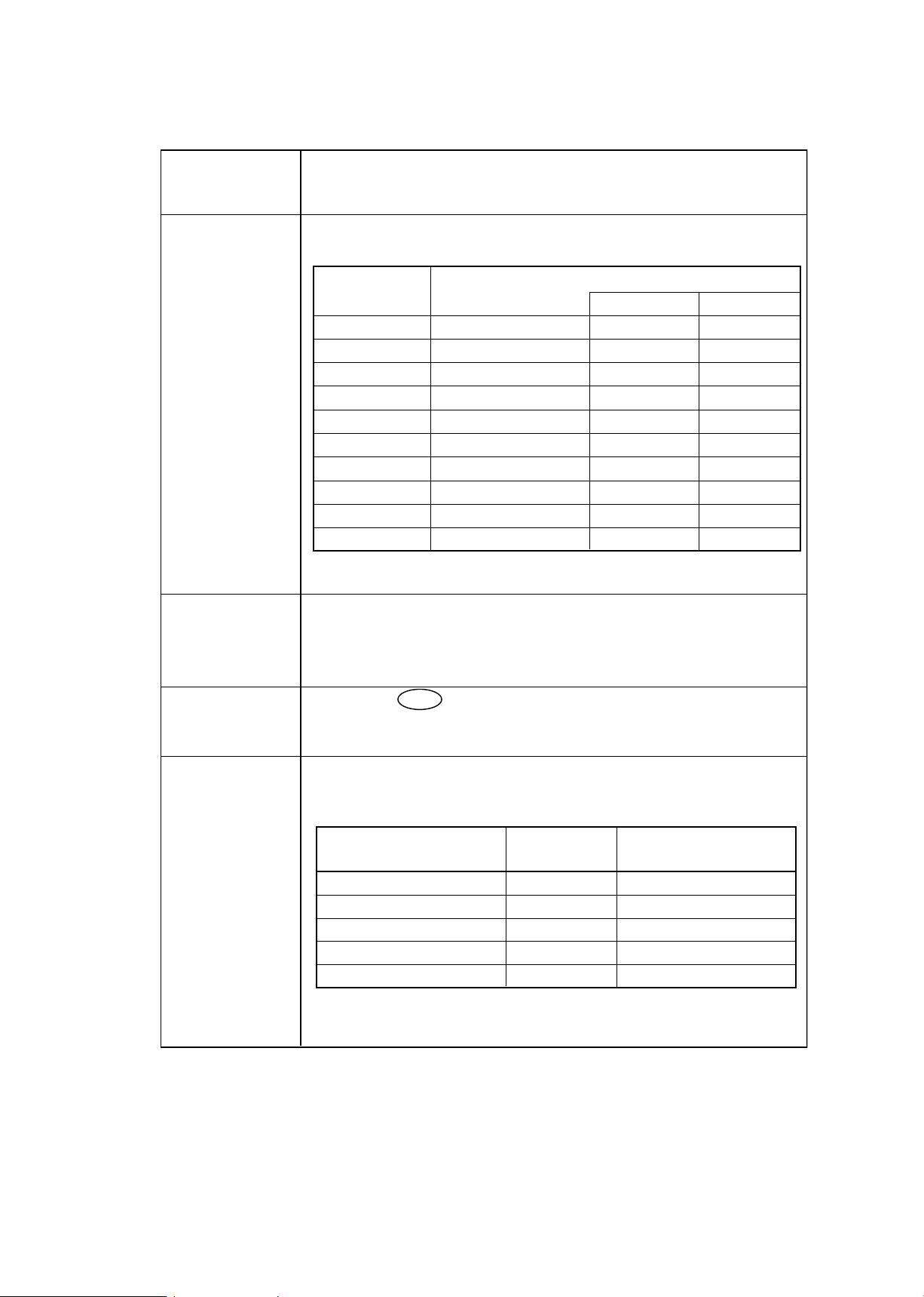
Guide number (at 35mm
zoom-head position,
20 C/68 F)
38/125 (ISO 100, m/ft), 53/174 (ISO 200, m/ft)
Flash shooting distance
range (TTL auto flash/
Auto Aperture flash/
Non-TTL auto flash)
0.6m to 20m (2 to 66 ft.) (varies depending on the
ISO sensitivity, zoom-head position, and lens aperture
in use)
Flash exposure control
Indicator Available flash mode
i-TTL mode Cameras compatible with CLS
No limitation
No limitation
No limitation
Digital SLRs not compatible with CLS
Cameras in Groups I to VI (film based cameras)
Cameras compatible with CLS, digital SLRs not
compatible with CLS, cameras in Groups I to IV
(No o appears with cameras in Groups III to IV)
Cameras compatible with CLS, digital SLRs not
compatible with CLS, cameras in Groups I to II
D-TTL mode
TTL (film based) mode
Balanced Fill-Flash
Auto Aperture flash
Non-TTL auto flash
Distance-priority
manual flash
Repeating flash
No limitation
Manual flash
Usable camera
Available multiple flash Usable camera
Advanced Wireless Lighting Cameras compatible with CLS
SU-4 type wireless multiple flash No limitation
Multiple flash shooting using cords No limitation
Other available functions Test firing, Monitor Preflashes, AF-assist
illuminator, and Modeling illuminator
A variety of flash operations are available with camera’s
compatible with CLS: i-TTL mode, Advanced Wireless
Lighting, FV Lock flash, Flash color information
communication, Auto FP High-Speed sync, and Wide-area
AF-Assist Illuminator
Creative
Lighting
System
Multiple flash
operation
SPECIFICATION
INC
* CLS = Creative Lighting System
FSA03501-R.3613.A
Group Camera
CLS compatible D2H
CLS not compatible D1series・D100
A F5・F100・F90series・F80series・F75・F70
B F4・F65・F801series・PRONEA 600i
C F601・F601M
D F60・F50・F401X
E F501・F401S・F401・F301
F FM3A・FA・FE2・FG・NIKONOS V・F3(AS-17)
G NewFM2・FM10・FE10・F3・F55
- M1・SB-800 -
FSA03501-R.3613.A
Bounce
capability
Flash head tilts down to
–7 or up to 90 with click-stops at –7 ,
0 , 45
, 60 , 75 , 90 ; flash head rotates horizontally 180 to
the left or 90
to the right with click-stops at 0 , 30 , 60 ,
90
, 120 , 150 , 180
Press the button for approx. 0.3 sec. to turn the
SB-800 on or off.
ON/OFF
button
Standby function can be set.
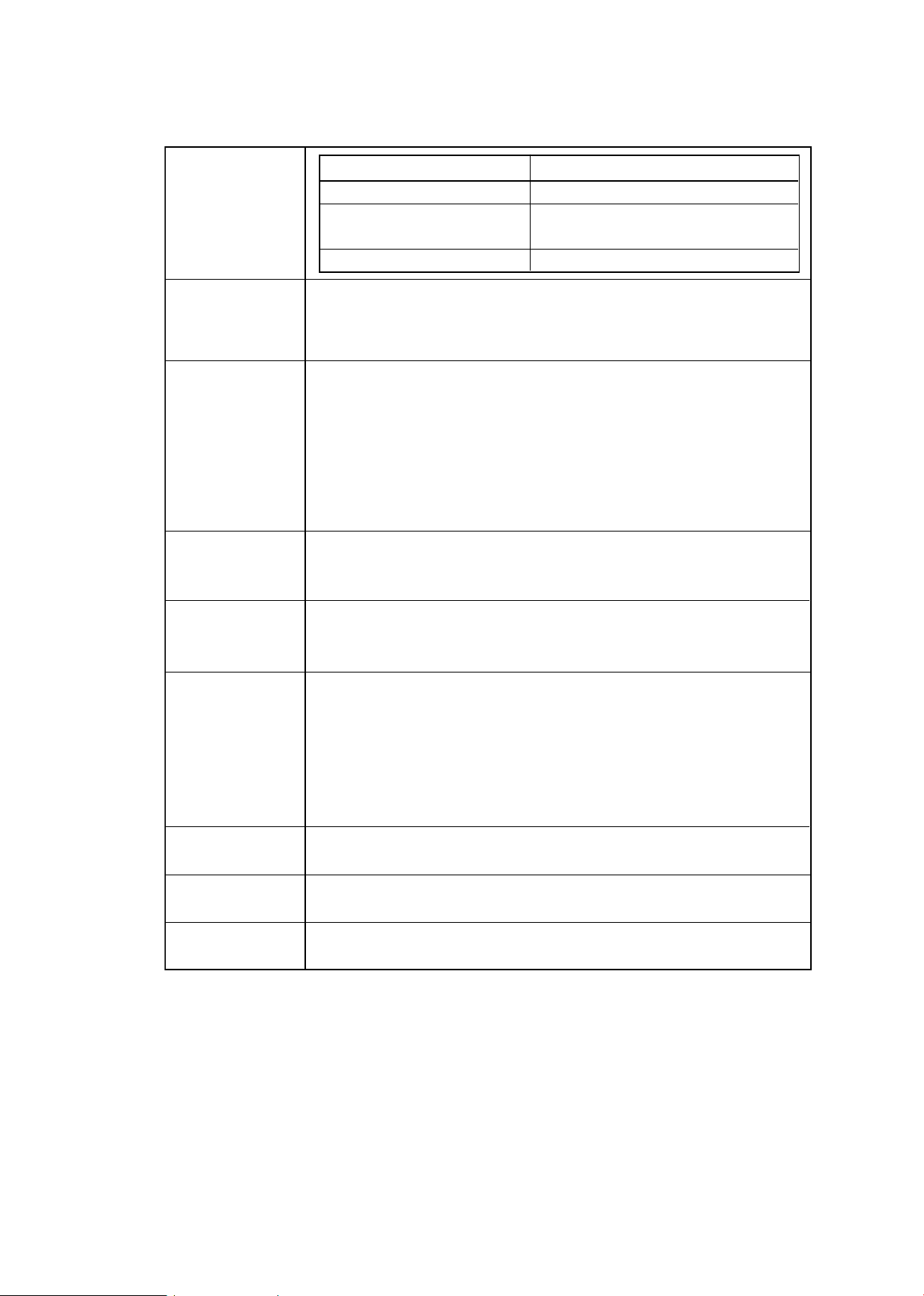
Power source/
min. recycling
time/no. of
flashes
(at M1/1 output)
Four AA-type penlight batteries (1.5V or lower) of any of these
types: Alkaline-manganese (1.5V), Lithium (1.5V), Nickel (1.5V),
NiCd (rechargeable, 1.2V), or Ni-MH (rechargeable, 1.2V)
*
With fresh batteries.
n M1/1 output without use of AF-assist illuminator, zoom operation,
and LCD panel illuminator.
Battery type Min. recycling
time (approx.)*
Min. number of flashes/
recycling time (approx.)*
Alkaline-manganese 6.0 sec. 130/6–30 sec.
Lithium 7.5 sec. 170/7.5–30 sec.
Nickel 6.0 sec. 140/6–30 sec.
NiCd (1000mAh) (rechargeable)
4.0 sec. 90/4–30 sec.
Ni-MH
(2000mA) (rechargeable)
4.0 sec. 150/4–30 sec.
Slow-sync, Red-eye reduction, Red-eye reduction in
slow-sync, Rear-curtain sync flash, Auto FP High-Speed
sync, FV Lock flash
Flash exposure
control set on
the camera
Angle of
coverage
Variable in 7 steps, plus three steps with wide-flash adapter
and Nikon Diffusion Dome
*
1
With the Nikon Diffusion Dome attached
*
2
With the built-in wide-flash adapter set
Zoom-head
position
Angle of coverage
Vertical Horizontal
14mm 14mm 110 120
14mm 14mm 110 120
17mm 17mm 100 110
24mm 24mm 60 78
28mm 28mm 53 70
35mm 35mm 45 60
50mm 50mm 34 46
70mm 70mm 26 36
85mm 85mm 23 31
105mm 105mm 20 27
*
1
*
2
*
2
INC
ON/OFF
- M2・SB-800 -
FSA03501-R.3613.A
Other
functions
Recalling the underexposure value in the TTL auto flash mode,
Resetting the settings, Button lock
Built-in wide- Allows SB-800 to be used with 14mm or 17mm lens
flash adapter
Dimensions Approx. 70.5 x 129.5 x 93.0mm (2.8 x 5.1 x 3.7 in.)
(W x H x D)
Mounting foot
Provides secure attachment of SB-800 to camera’s accessory
shoe using locking plate and mount pin to prevent accidental
detachment.
lock lever
Flash output
level
compensation
–3.0 to +3.0 EV in increments of 1/3 steps in the TTL auto
flash, Auto Aperture flash modes and Distance-priority
manual flash
Custom
settings
By pressing the g and ef, c or d buttons, the following
custom settings are possible: ISO sensitivity, Wireless flash
auto, Sound monitor in the wireless flash mode, Non-TTL auto
flash, Standby function, Selecting the distance unit (m, ft.),
Canceling power zoom function, Power zoom function using
the built-in wide-flash adapter/Nikon Diffusion Dome, LCD
panel illuminator, Brightness of the LCD panel, AF-assist
illuminator, and canceling flash firing.
External power
sources
(optional)
Ready-light
Lights up when the SB-800 is recycled and ready to fire.
Blinks for 3 sec. when flash fires at its maximum output, indicating
light may have been insufficient (in TTL Auto Flash, Auto Aperture
B Flash and Non-TTL Auto Flash A operations)
Flash 1/1050 sec. at M 1/1 (full) output
duration 1/1100 sec. at M 1/2 output
(approx.) 1/2700 sec. at M 1/4 output
1/5900 sec. at M 1/8 output
1/10900 sec. at M 1/16 output
1/17800 sec. at M 1/32 output
1/32300 sec. at M 1/64 output
1/41600 sec. at M 1/128 output
External power source Battery type
DC Unit SD-7 Six C-type alkaline-manganese
High-Performance Battery Six AA-type alkaline-manganese
Pack SD-8A
Power Bracket Unit SK-6 Four AA-type alkaline-manganese
INC
- M3・SB-800 -
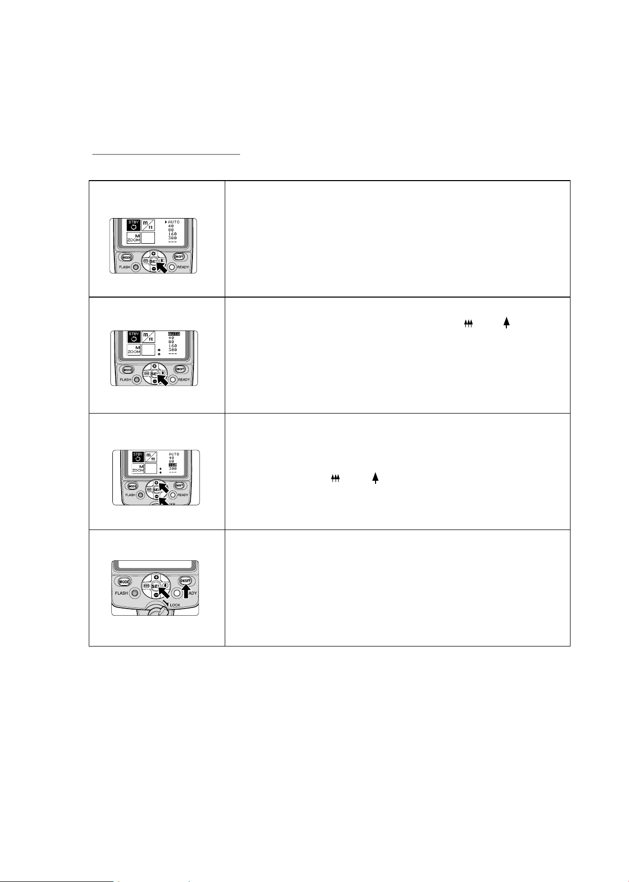
Setting Custom functions
INC
FSA03501-R.3613.A
Custom settings
1. Press the [ SEL ] button for approx. 2 sec.
to display the Custom settings mode.
2. Press the [ + or - ] button and [ or ]
button on the Multi Selector to choose
the desired custom functions to be set,
then press the [ SEL ] button.
3. Press the [ + or - ] button to highlight the
preferred setting.
Press the [ or ] button to adjust
the “LCD panel brightness”
4. Press the [ SEL ] button for approx. 2 sec. or
press the [ ON/OFF] button to return to
the normal setting mode.
- M4・SB-800 -
INC
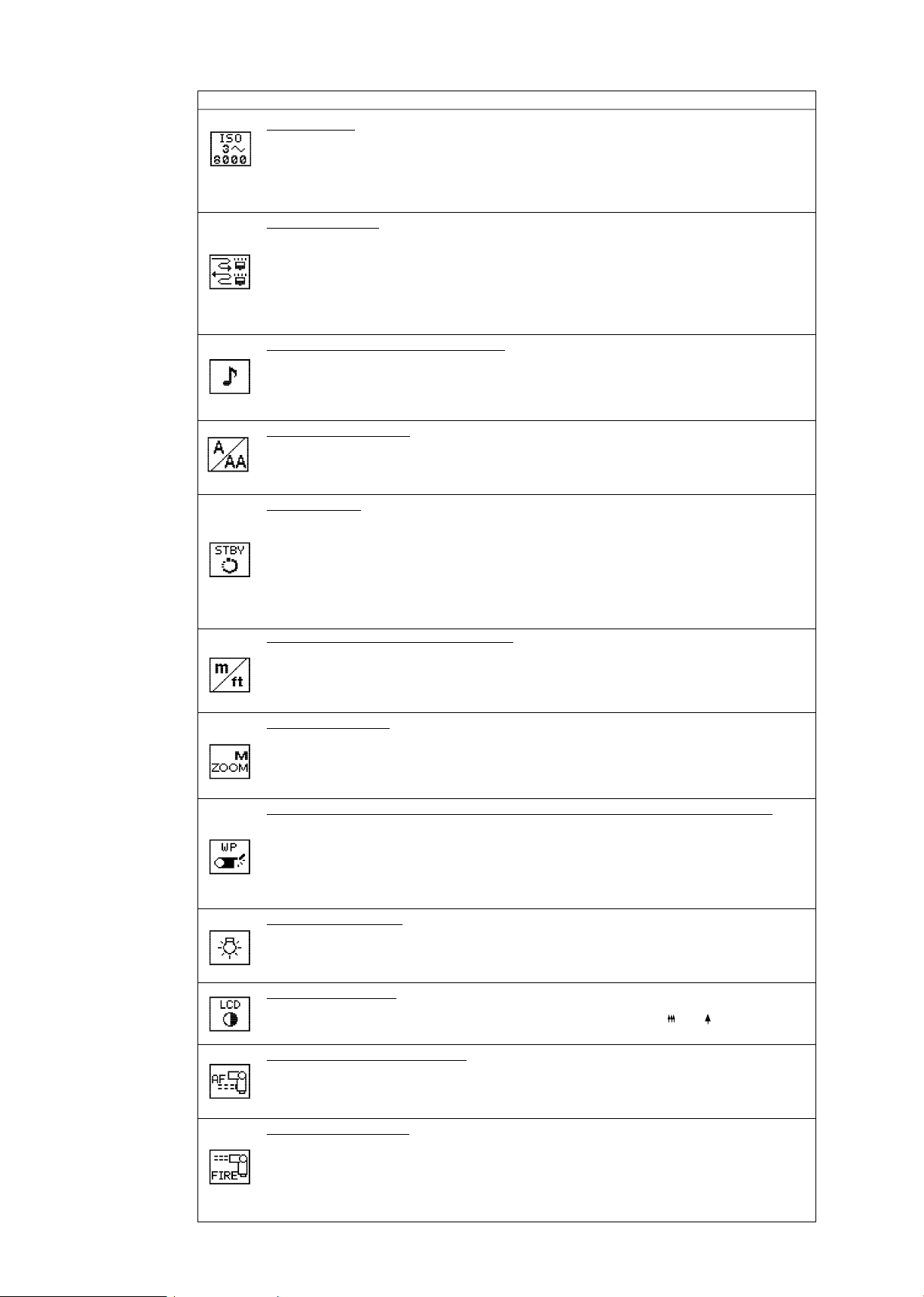
Details on Custom settings (RED = default setting)
ISO sensitivity
The available ISO sensitivity range is ISO 3 to 8000. Pressing the [ + / - ] button
increases or decrease the value
in increments of 1/3 step. Pressing the [ + / - ] button continuously increases or
decreases the value quickly.
• 100
Wireless flash mode
Setting the flash mode in wireless multiple flash photography.
• OFF : Canceled
• MASTER : Master flash unit in the Advanced Wireless Lighting mode
• MASTER (RPT) : Master flash unit in the Advanced Wireless Lighting mode
(in Repeating flash)
• REMOTE : Remote flash unit in the Advanced Wireless Lighting mode
• SU-4 : SU-4 type wireless flash mode
Sound monitor in the wireless flash mode
When the SB-800 is used as a wireless remote flash unit, you can activate
or cancel the sound monitor function.
• ON : Sound on
• OFF : Sound off
Non-TTL auto flash mode
Setting the Non-TTL auto flash mode.
• AA : Auto Aperture flash
• A : Non-TTL auto flash
Standby function
Adjusting the time before the standby function is activated.
• AUTO : With a camera body that is compatible with TTL auto flash ,
the SB-800 turns off when the camera’s exposure meter turns off.
• 40 : 40 sec.
• 80 : 80 sec.
• 160 : 160 sec.
• 300 : 300 sec.
• - - - : Standby function canceled
Selecting the distance unit of measure
Setting the distance unit of measure on the LCD panel to either
meters “m” or feet “ft”.
• m : meters
• ft : feet
Power zoom function
Setting to activate or cancel the power zoom function, which adjusts the zoom-head
position automatically.
• OFF : Activated
• ON : Canceled
Power zoom function using the built-in wide-flash adapter/Nikon Diffusion Dome
Setting to activate or cancel the power zoom function using the built-in wide-flash
adapter/Nikon Diffusion Dome. The same is true when using the built-in wide-flash
adapter.
When set to ON, the zoom-head position display is framed.
• OFF : Canceled
• ON : Activated
LCD panel illuminator
Setting the LCD panel illuminator to turn on or off.
• ON : Turn on
• OFF : Turn off
LCD panel brightness
Adjusting the brightness of the LCD panel. Available brightness levels are
graphically displayed in 9 steps on the LCD panel. Press the or button to
adjust the brightness.
Wide-Area AF-Assist Illuminator
Setting to activate or cancel the Wide-Area AF-Assist Illuminator.
• ON : Activated (AF-ILL appears on the LCD panel)
• OFF : Canceled (NO AF-ILL appears on the LCD panel)
Canceling flash firing
Setting to activate or cancel flash firing of the SB-800.
When it is set to OFF, the SB-800 does not fire but the Wide-Area AF-Assist
Illuminator still comes on.
• ON : Firingactivated
• OFF : Firing canceled (AF-ILL ONLY appears on the LCD panel)
FSA03501-R.3613.A
- M5・SB-800 -
Disassembly
INC
FSA03501-R.3613.A
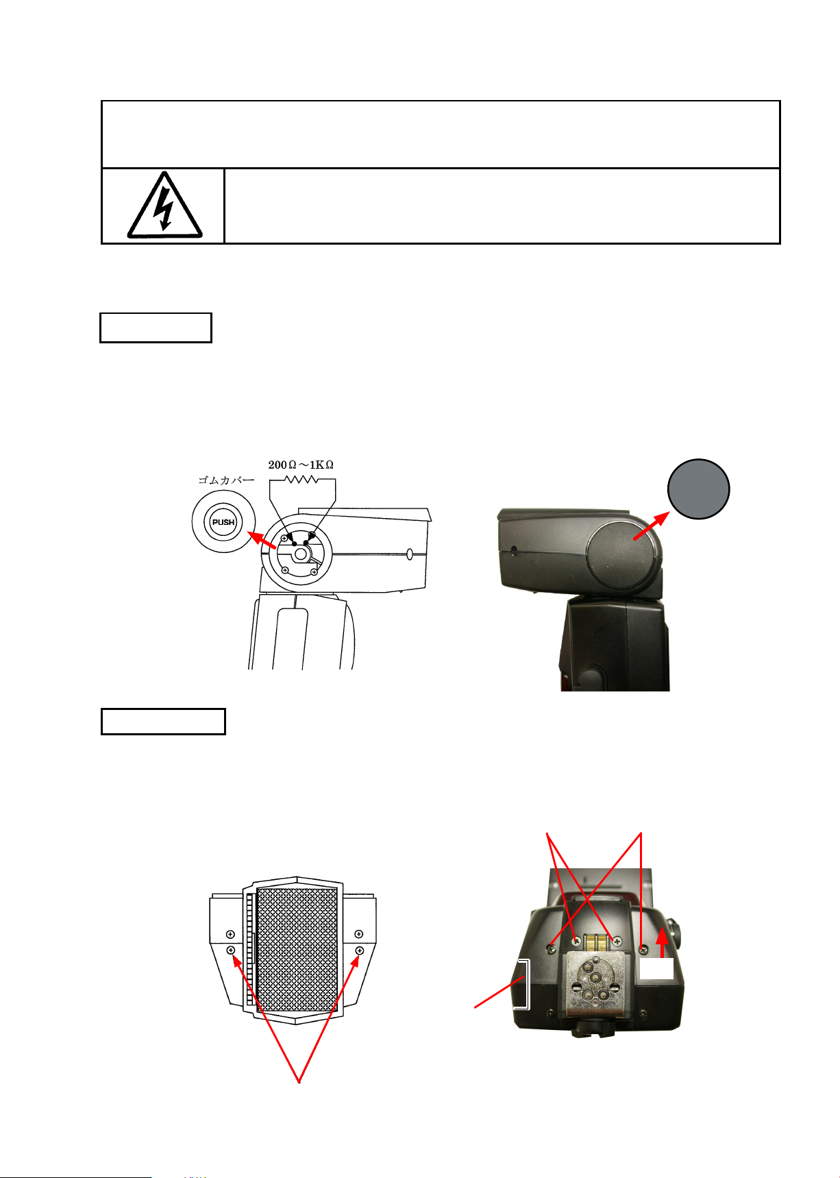
WARNING
●
Due to an internal high voltage area, be
removing covers according to the instructions of the repair manuals.
*Note:For dissembling/(re)assembling this product, lead-free solder is used except both ends of
Xe-tube on Page D8/A3.
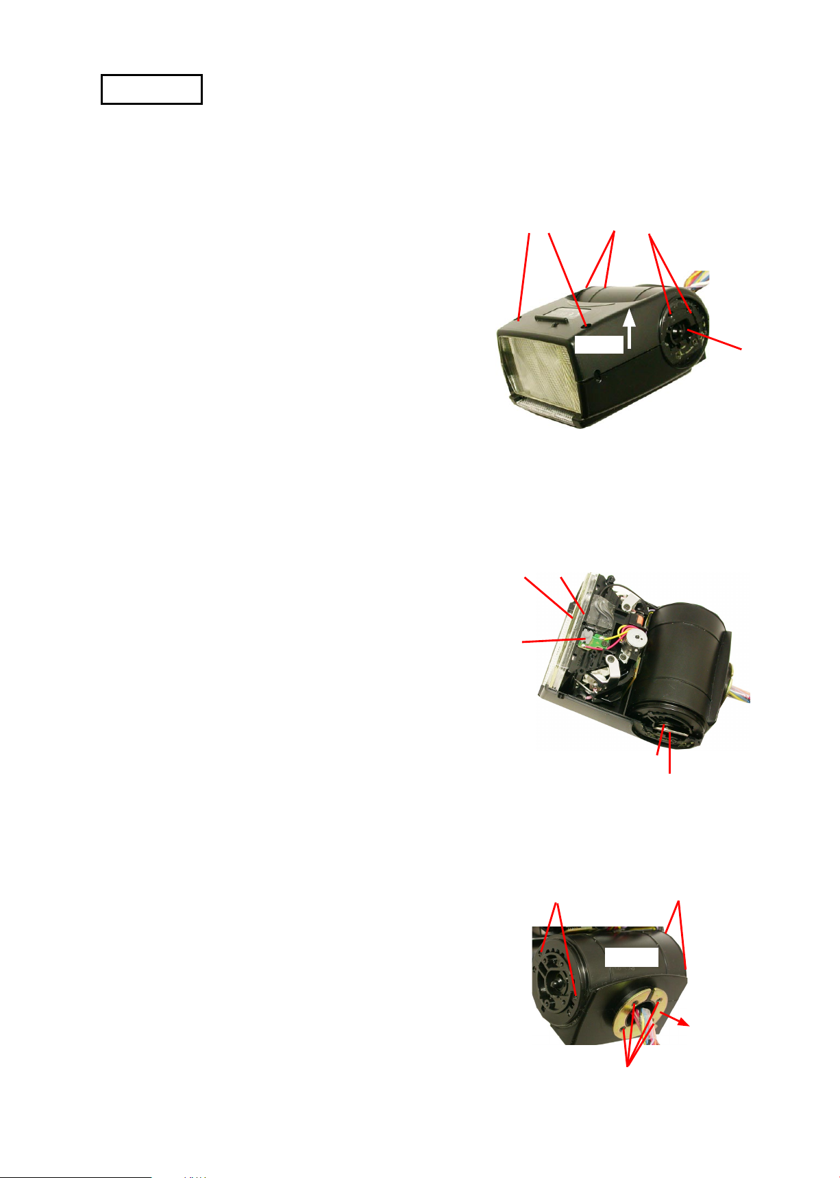
Side Rubber
・ Remove right-and-left side rubbers.
・Discharge the main condenser at 2 holes under the side rubbers (#143) by using
discharging tool.
#143
警告
sure to discharge the main condenser before
#144
Cover (E) unit
・Take out each screw, and lift the cover (E) unit (#118) up slowly
in the direction indicated by the arrow.
* Note: Be careful not to cut off the inside wires.
・The battery lid comes off.
Battery lid
#103×2
#161×2
#136×2
#118
- D1・SB-800 -
INC
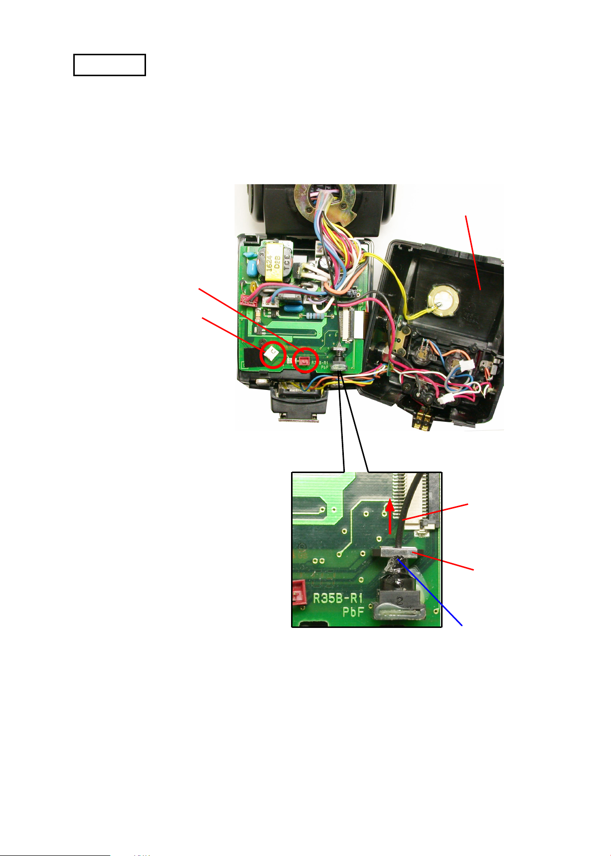
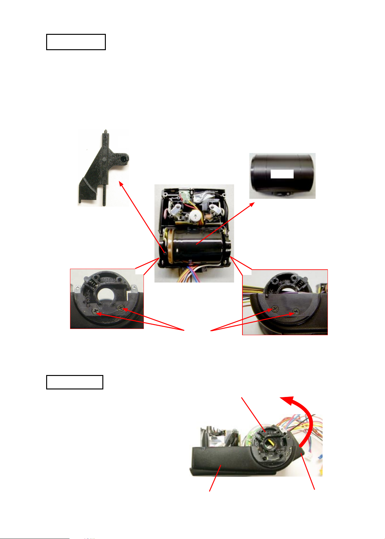
Fiber ①
・Detach the connectors
(CN16 and CN8) from
the cover (E) unit.
FSA03501-R.3613.A
Cover (E) unit
CN 16
CN 8
Fiber retainer
・Detach the fiber retainer.
・Pull the fiber in the direction indicated by the arrow.
* Note: Be careful NOT to bend the fiber when disassembling and (re)assembling.
Fiber
Attached with glue
- D2・SB-800 -
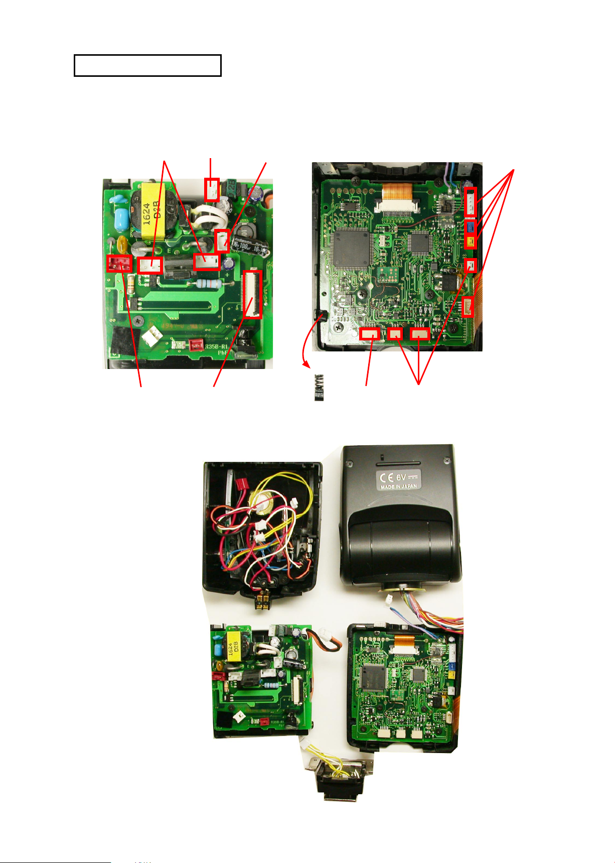
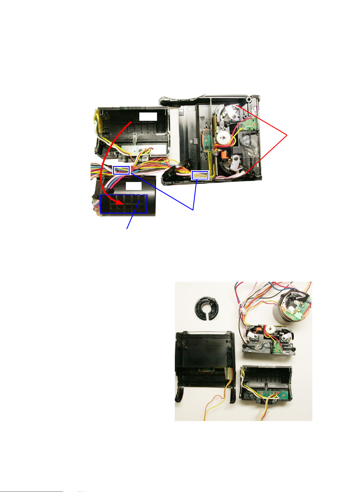
Separation into each unit
INC
・By disconnecting each connectors, separate into each unit.
* Note: Be careful NOT to lose the click post and spring.
FSA03501-R.3613.A
Head unit
Cover (E) unit
A-PCB
A-PCB
Battery chamber
Click post
・Spring
Leg unit
Head unit
Cover (E) unit
Cover (E) unit
B-PCB+Battery chamber
Head unit
A-PCB +LCD unit
Leg unit
- D3・SB-800 -
INC
Head unit
・Take out 6 screws and detach the cover (B) in the direction
indicated by the arrow.
* Note: Be careful of jump out of U/D stopper metals (#45)
and the U/D bounce spring (#45) of the A unit.
# 16×2
FSA03501-R.3613.A
# 36×4
Cover (B)
A unit
・Remove the U/D stopper metal (#45) and U/D bounce
spring (#44).
・Remove the acrylic panel (#43) and fresnel lens (#42).
・Remove the detection SW (#22).
・Take out 4 screws (#31) of the cover (D) unit.
#22
#43
#42
#31×2
#44
#45
#31×2
・Take out 4 screws (#41) and remove the turning plate (#40).
Cover (D)
#40
#41
- D4・SB-800 -
INC
Cover (D) unit
・Detach the cover (D) unit.
・Detach L/R lock knob (#25).
・Take out 4 screws (#36).
# 25
FSA03501-R.3613.A
Cover D
Cover (C) unit
・Detach the cover (C) from the head unit by turn-
ing it in the direction indicated by the arrow.
・The bounce shaft A comes off.
- D5・SB-800 -
#36×4
Bounce shaft A
Head unit
Cover (C)
・Detach the main condensor (#169) from the cover (C) by pulling it.
INC
(Both-sided adhesive tape (#37) is attached.)
・Take out 2 screws (#16).
Body C
#169
FSA03501-R.3613.A
# 16×2
#37
・Remove the tapes that attach the wires at the
above 2 parts, then each unit comes off as
shown in the right.
Tape to arrange wires
- D6・SB-800 -
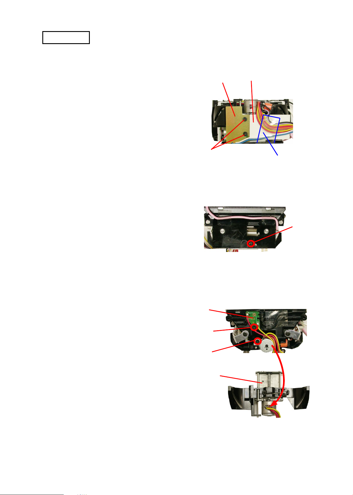
Motor unit
INC
FSA03501-R.3613.A
・Remove the tape to release wires that are arranged
by the both-sided adhesive tape on the tetrone
sheet.
・Take out 2 screws (#65) to detach the H-PCB.
・Take out the screw (#31).
H-PCB
#65×2
Tetrone sheet
Tape
#31
・Take out the screw (#183) to detach the K-PCB.
・Take out the screw (#78) to detach the motor unit.
- D7・SB-800 -
K-PCB
#183
#78
Motor unit
FSA03501-R.3613.A
INC
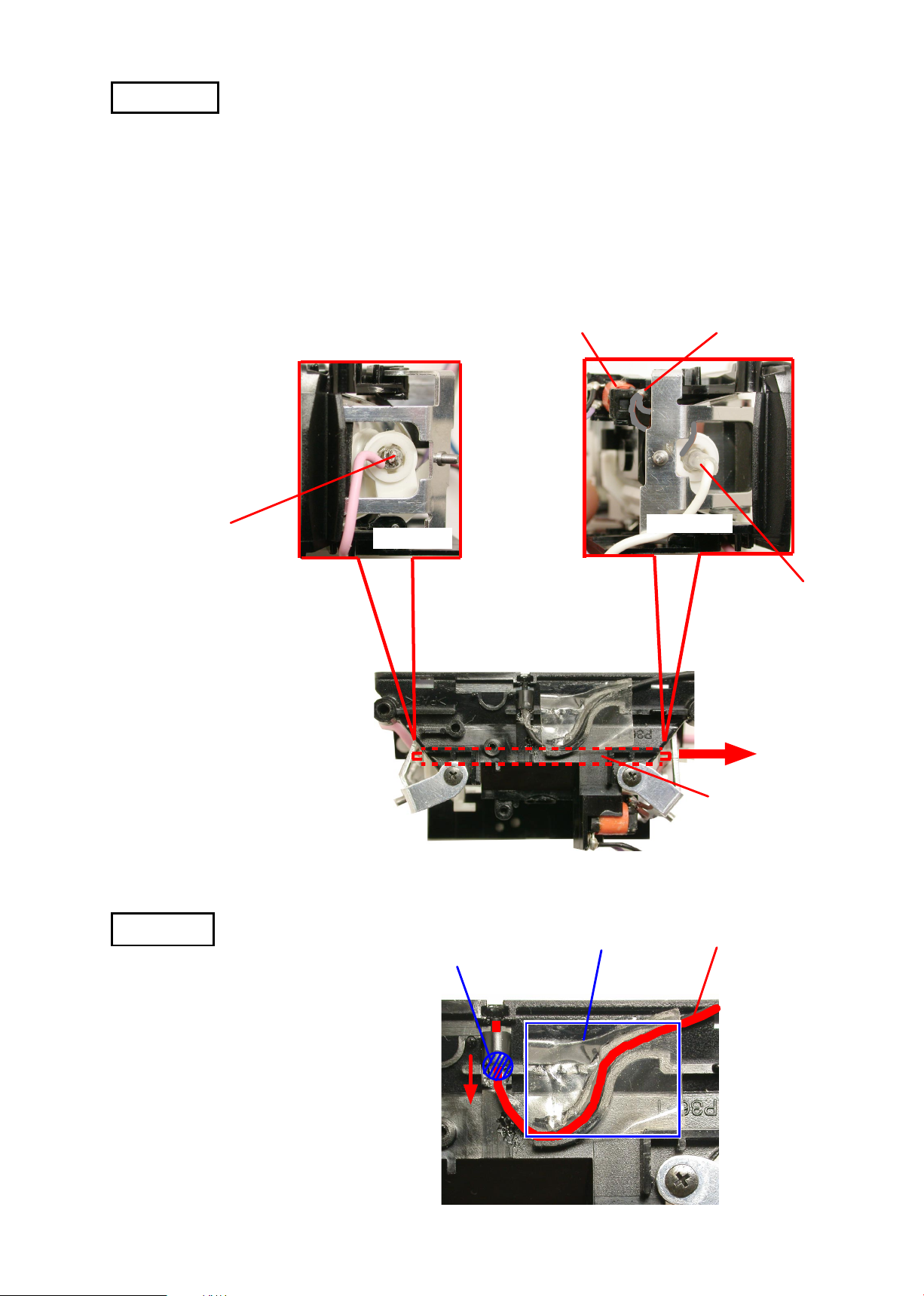
Xe-tube
・Cut out the heat contraction tube on the + side of Xe-tube with nipper, etc, and remove the solder of the pink
wire.
・On the trigger coil side, remove the solder of the trigger lead wire (Gray) that connects the - side of Xe-tube.
・Detach the Xe-tube in the direction indicated by the arrow.
・Cut out the heat contraction tube on the -side of Xe tube with nipper, etc, and remove the solder of the white
wire.
Gray: Trigger lead wire
Pink
lead solder
Xe tube + side
Trigger coil
lead-free solder
Xe tube - side
White
lead solder
Fiber ②
・Remove the tape.
・Detach the fiber in the direction indicated
by the arrow.
Attached with glue
Tape
Xe-tube
Fiber
- D8・SB-800 -
FSA03501-R.3613.A
INC
Assembly
* Note: For dissembling/(re)assembling this product, lead-free solder is used except for both ends of Xe-tube.
・For assembling work for both ends of Xe-tube on Page A3, use lead solder. For the other all works,
use lead-free solder.
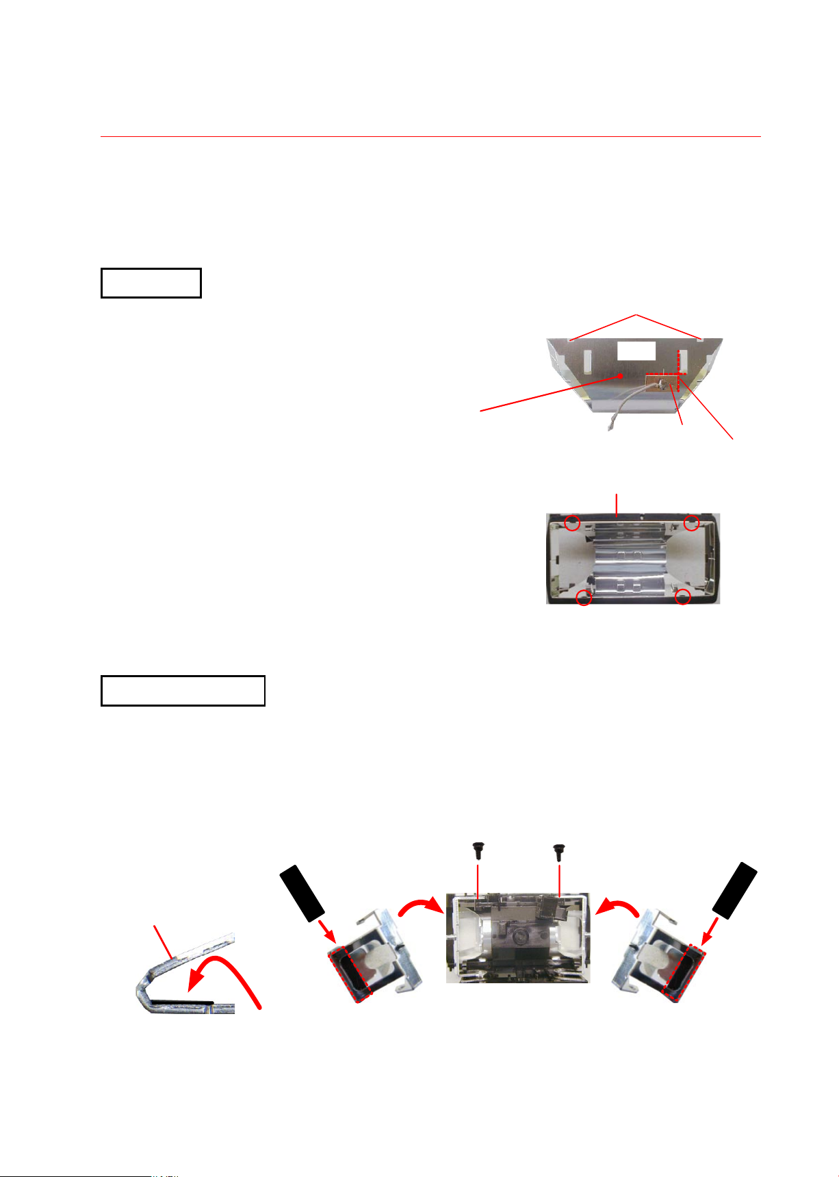
Reflector
・Attach the conductive tape (#82) on the reflector (#77).
・Solder the trigger lead wire (#184).
Notch
# 77
Surface with wider spacing
between notches
・Attach the reflector to the reflector case (#75).
* Note: Hook the notches of the reflector to 4 parts of
the reflector case.
Reflector side plate
・Attach 2 shade sheets (#185) inside the reflector side plates (#79, #80).
・Attach the reflector side plate to the reflector case.
・Attach 2 screws (#81).
Gray:#184
#75
#82
Attaching
position
Mirror surface side
Attach #185 inside.
#185
#80
- A1・SB-800 -
#81×2
#185
#79
INC
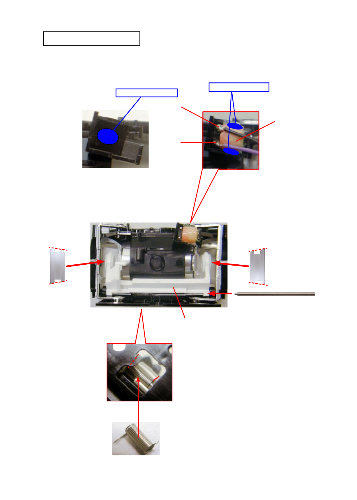
Trigger coil / Xe-holder unit
・Attach the trigger coil (#75) with glue and solder black and purple wires.
Adhesive: Cemedine 575
Adhesive: Cemedine 575
Black
CN-3
Purple
CN-3
FSA03501-R.3613.A
#75
#72
#72
#73: Direction of insertion
#71
・
Attach 2 Xe-rubber bushes (#72) to the Xe-holder (#71)
and assemble it into the reflector case.
#74: Spring hook
#74
- A2・SB-800 -
 Loading...