

Page 1

Instruction Manual
En
SB-27
SB-27
Autofocus SpeedlightAutofocus SpeedlightAutofocus Speedlight
Page 2
2
Foreword
Thank you for purchasing the Nikon Autofocus
Speedlight SB-27, an easy-to-use flash unit offering you
the most convenient system for automatic flash
photography in combination with Nikon cameras. The
SB-27’s extensive capabilities range from Non-TTL Auto
Flash to 3D Multi-Sensor Balanced Fill-Flash, today’s
most advanced flash technology.
For optimum results, be sure to read this manual
thoroughly before use.
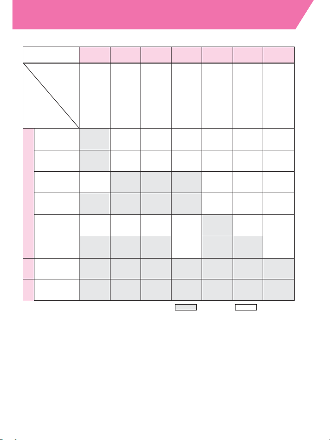
Please check which group your camera belongs to.
In this manual, we have divided Nikon SLR cameras into seven
groups (from I to VII) unless otherwise noted. You will find all the
information you need to learn about using the SB-27 with your
camera in the section corresponding to your camera group.
Please refer to the camera group table on the following page.
Ⅰ Ⅱ Ⅲ Ⅳ Ⅴ Ⅵ Ⅶ
Group
Cam
era
nam
e
Flash
operation
F
5
0
1
/
N
2
0
2
0
*
8
F
4
0
1
s/
N
4
0
0
4
s
*
1
F
4
0
1
/
N
4
0
0
4
*
1
F
3
0
1
/
N
2
0
0
0
*
8
F
5
F
1
0
0
F90X/N90
*
1
s
F90-Series/
N90
*
1
F80-Series/
N
8
0
S
e
r
i
e
s
*
1
,
*
3
F70-Series/
N70
*
1
F
4
S
e
r
i
e
s
F65-Series/
N65-Series
*
1
F
-
8
0
1
s/
N
8
0
0
8
s
*
1
F
-
8
0
1
/
N
8
0
0
8
*
1
Pro
n
e
a6
0
0
i/
6i
*
1
,
*
3
F
6
0
1
/
N
6
0
0
6
*
1
F
6
0
1
M
/
N
6
0
0
0
*
1
F
6
0
Series/
N
6
0
*
1
F
5
0
Series/
N
5
0
*
1
F
4
0
1
x/
N
5
0
0
5
*
1
F
A
F
M
3
A
F
E
2
F
G
Nikonos
V
*
5
F3-Series
*
6
N
e
w
F
M
2
F55-Series/
N55-Series
*
1
F
M
1
0
F
E
1
0
3
D
M
u
lt
i
-S
e
n
s
o
r
B
a
la
n
c
e
d
F
ill-
F
la
s
h
*
2
M
u
lti-
S
e
n
s
o
r
B
a
la
n
c
e
d
F
ill-
F
la
s
h
*
2
M
a
t
r
ix
B
a
la
n
c
e
d
F
ill-
F
la
s
h
C
e
n
t
e
r
We
ig
h
te
d
F
ill-
F
la
s
h
/
S
p
o
t
F
ill-
F
la
s
h
S
ta
n
d
a
r
d
T
T
L
F
la
s
h
P
r
o
g
r
a
m
m
e
d
T
T
L
A
u
t
o
F
la
s
h
N
o
n
T
T
L
A
u
to
F
la
s
h
*
7
M
a
n
u
a
l F
la
s
h
T
T
L
M
A
**
4
: Available : Not available
Page 3
3
Camera groups
*1 Sold exclusively in the USA.
*2 3D Multi-Sensor Balanced Fill-Flash and Multi-Sensor
Balanced Fill-Flash are generally referred to as Automatic
Balanced Fill-Flash with TTL Multi Sensor.
*3
Center-Weighted Fill-Flash/Spot Fill-Flash is not possible.
*4
Some flash functions are controlled on camera.
*5
An optional sync cord for land use is required.
*6 Optional flash Unit coupler AS-4 or AS-7 is required. With AS-17, Standard TTL flash
is possible, but not Repeating flash.
*7 See page 69 for cameras in groups I through VI, and page 38 for cameras in
group VII.
*8
Sold exclusively in the USA and Canada.
*For cameras such as the Nikon F or Nikon F2, refer to Group VII.
NOTE: For details on the SB-27's available TTL Auto Flash
operations, see the separate Quick Reference sheet and the
Glossary of terms on pages 83 to 88.
1
*
1
F-601/
N6006
F-601M/
N6000
4
F60-
1
N60
*
F50-
1
N50
*
F-401x/
N5005
F-501/
Series/
1
N2020
*
F-401s/
Series/
1
N4004s
*
F-401/
1
N4004
*
F-301/
N2000
: Available : Not available
FM3
8
*
FA
FE2
1
*
FG
1
Nikonos
*
8
*
A
5
V
*
F3-Series
F55-Series/
N55-Series
New FM2
FM10
FE10
Group
Camera
name
Flash
operation
3D Multi-Sensor
Balanced
Fill-Flash
*
Multi-Sensor
Balanced
Fill-Flash
*
Matrix
Balanced
T
Fill-Flash
T
Center-Weighted
L
Fill-Flash/Spot
Fill-Flash
Programmed
TTL AutoFlash
Standard
TTL Flash
Non-TTL
A
Auto Flash
Manual Flash
M
Ⅰ Ⅱ Ⅲ Ⅳ Ⅴ Ⅵ Ⅶ
F4-Series
F65-Series/
1
N65-Series
s
*
F-801s/
1
N8008s
1
3
,
*
F-801/
N8008
Pronea 600
1
3
,
6i
*
*
*
1
*
i/
*
*
1
*
2
2
*
7
F5
F100
F90X/N90
F90-Series/
N90
F80-Series/
N80-Series
F70-Series/
N70
**
6
*
1
*
Page 4
About this manual
The instruction materials comprise the main manual and a
separate Quick Reference sheet.
• In the main manual, we begin with instructions on preparing the
Speedlight for shooting and move on to a variety of basic and
advanced flash photographic techniques covering all available
functions.
• In the separate Quick Reference sheet, we explain some basic
flash photographic procedures.
• Nikkor lenses have been roughly divided into two types as
shown below unless otherwise noted.
* Except AF Nikkor lenses for F3AF
** IX Nikkor lenses are designed for use with the Nikon Advanced Photo System (IX240)
format SLR camera body only and cannot be used with 35mm SLR cameras.
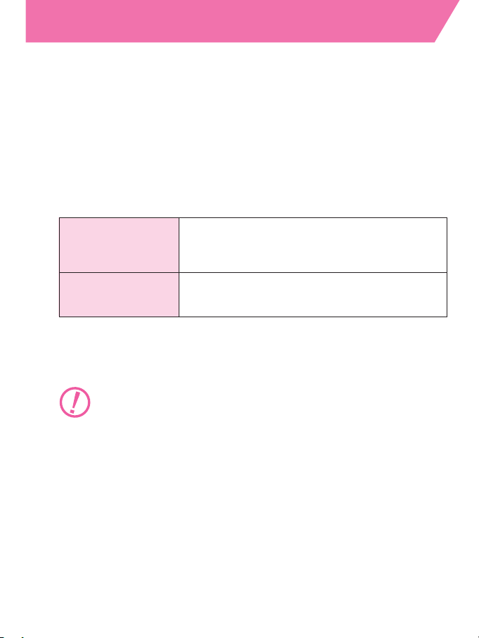
Notices used in this manual
Denotes important points where caution or mandatory action is
required.
NOTE Denotes a useful point that should be remembered for future
reference.
Nikkor lenses • D- or G-type Nikkor lenses
with built-in CPU • IX Nikkor lenses**
• Non-D/G-type AF Nikkor lenses*
AI-P-type Nikkor lenses
Nikkor lenses • AI-S-type or AI-type Nikkor lenses
without built-in CPU • Nikon Series E lenses
• AI-modified Nikkor lenses and others
Page 5
Tips on using the Speedlight
5
■Take some trial shots.
Before taking important flash photographs, take a few trial shots
first to make sure the Speedlight is working properly.
■Use only Nikon-approved equipment.
Your Speedlight has been designed for use in combination with
Nikon cameras, lenses and accessories.
—Using cameras or accessories other than those specified by Nikon
may damage your Speedlight.
—Nikon cannot be held responsible for malfunctions caused by using
the SB-27 in ways not specified in this manual, or using the SB-27 with
a camera made by another manufacturer.
■For further details on camera operation, read the
instruction manual provided with each camera
before use.
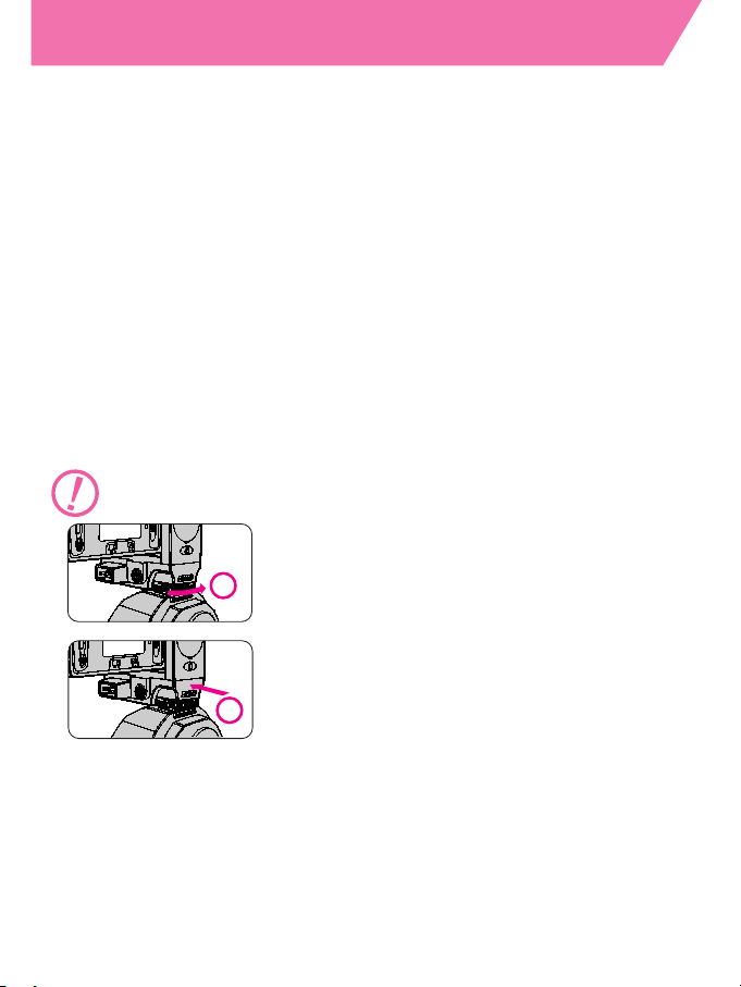
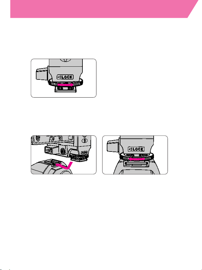
Take special care when detaching the SB-27 from your camera.
1
For cameras with a safety lock system: loosen
the mounting foot locking wheel all the way in
the direction of arrow ➀, and slowly detach the
SB-27.
2
If the mounting foot locking wheel doesn’t
loosen easily, do not force it. Push the foot
forward gently once in the direction of arrow ➁
and try loosening the wheel again.
Page 6

Contents
6
Foreword
.......................................
2
Camera groups
.....................................
3
About this manual
...................................
4
Tips on using the Speedlight
...........................
5
Contents
.........................................
6-7
Speedlight parts
....................................
8
LCD panel indications
................................
9
Preparations for taking flash photographs
......
10
Installing batteries
..................................
11
Standby function
.................................
12-13
Attaching the SB-27 to the camera
......................
14
Adjusting the flash head
..............................
15
Selecting a measurement system (meters/feet)
.............
16
The ready-light
.....................................
17
Test firing with the open-flash button
.....................
18
Setting ISO film speed
...............................
19
Setting zoom-head position
.........................
20-21
Basic flash operation
...........................
22
Selecting a flash mode
...............................
23
Flash operation in AUTO mode (Cameras in Group I:
F5, F100, F90X/N90s, F90-Series/N90, F80-Series/N80-Series,
F70-Series/N70)
.................................
24-25
Flash operation in AUTO mode (Cameras in Group II:
F4-Series, F65-Series/N65-Series, F-801s/N8008s,
F-801/N8008, Pronea 600i/6i)
........................
26-27
Flash operation in AUTO mode (Cameras in Group III:
F-601/N6006, F-601M/N6000)
........................
28-29
Flash operation in AUTO mode (Cameras in Group IV:
F60-Series/N60, F50-Series/N50, F-401x/N5005)
.........
30-31
Flash operation in AUTO mode (Cameras in Group V:
F-501/N2020, F-301/N2000)
.........................
32-33
Flash operation in AUTO mode (Cameras in Group V:
F-401s/N4004s, F-401/N4004)
.......................
34-35
Flash operation in AUTO mode (Cameras in Group VI:
FM3A, FA, FE2, FG, Nikonos V)
......................
36-37
Flash operation in AUTO mode (Cameras in Group VII:
F3-Series, F55-Series/N55-Series, New FM2, FM10, FE10) ..38-39
If the ready-light blinks after shooting
....................
40
Advanced flash operation
......................
41
Flash operation in Manual (M) mode
(For cameras in all groups)
.........................
42-45
Page 7

7
Guide numbers for determining correct aperture
............
46
Autofocus flash operation in dim light
(For AF SLR cameras only)
..........................
47-48
Bounce flash operation (For cameras in all Groups)
.......
49-53
Procedures for bounce flash operation
..............
51-52
Highlight your subject’s eyes with bounced flash
.........
53
Close-up flash operation in AUTO mode
(Cameras in Groups I thru VI)
.......................
54-59
Procedures
....................................
54
Close-up flash operation using an TTL Remote Cord
......
59
Exposure compensation for flash photography
(Cameras in Groups I thru III)
........................
60-62
Cameras in Groups I and II
.........................
61
Setting exposure compensation on the SB-27
...........
61
Canceling exposure compensation
...................
62
Cameras in Group III
.............................
62
Multiple flash operation—using more than one Speedlight
(Applicable to all camera groups)
....................
63-68
TTL multiple flash operation procedures
...............
64
System chart for TTL multiple flash
.................
66-67
Manual multiple flash operation procedures
............
68
Setting Forced TTL and Forced A modes
(Applicable to all camera groups)
....................
69-70
Setting and canceling Forced TTL and Forced A modes
...
69
Forced TTL mode
................................
69
Forced A mode
..................................
70
Canceling Forced TTL and Forced A modes
............
70
Red-eye reduction control
(For cameras in Group I [except F5] and Pronea 600i/6i)
......
71
Other information
..............................
72
Using an external power source
........................
73
Connecting the SB-27 to a camera with a sync cord
.........
74
Warning indications on the camera
......................
75
Troubleshooting
....................................
76
Optional accessories
..............................
77-78
Tips on Speedlight care
............................
79-80
Notes on batteries
................................
81-82
About NiCd batteries
.............................
82
Using the SB-27 in low temperatures
..................
82
Glossary of terms
................................
83-88
Specifications
...................................
89-91
Page 8
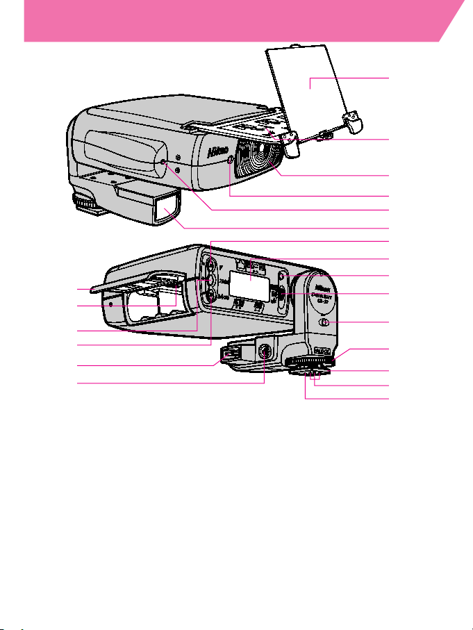
Speedlight parts
8
1
2
3
4
5
6
7
8
9
10
11
12
21
20
19
18
17
16
13
14
15
1 Built-in diffuser card (See page 53.)
2 Built-in bounce flash adapter (See page 52.)
3 Flash head (See page 15.)
4 Red-eye reduction lamp
5 Light sensor for Non-TTL Auto Flash
operation
6 AF assist illuminator LED (See page 47.)
7 “F” button (See pages 16, 25, 27, 29, 31,
33, 35, 37, 39 and 61.)
8 LCD panel (See page 9.)
9 Ready-light (See page 17.)
10 Flash mode selector (OFF / M / AUTO)
(See page 18.)
11 Open-flash button (See page 18.)
12 Mounting foot locking wheel (See page 14.)
13 Mounting foot (See page 14.)
14 Hot-shoe contacts (See page 14.)
15 Mount pin (See page 14.)
16 Battery chamber lid (See page 11.)
17 Camera setting switch (See pages 12, 69)
18 “ZOOM” button (See page 20.)
19 “M” (M/ISO) button (See pages 20, 23, 24,
26, 43 and 61./See page 19.)
20 External power source terminal
(See page 73.)
21 Sync terminal (See page 74.)
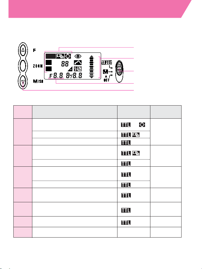
Page 9
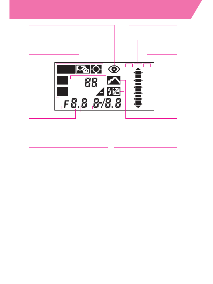
LCD panel indications
9
1 Red-eye reduction control indicator
2 Zoom-head position indicator
3 Flash mode indicator
Ø Automatic Balanced Fill-Flash
with TTL Multi Sensor
ø Matrix Balanced Fill-Flash
t Standard TTL Flash
˙ Non-TTL Auto Flash
ƒ Manual Flash
4 Aperture indicator
5 Underexposure indicator
6 Film speed indicator
7 Flash shooting distance scale (ft.)
8 Indicator bars (flash shooting distance
indicator bars)
9 Flash shooting distance scale (m)
10 Bounce flash indicator
11 Exposure compensation indicator
12 Light output /exposure compensation
value indicator
• LCDs are temperature sensitive, and may turn black at high
temperatures [approx. 40°C (104°F) or above] and become hard to
read.
• In cold temperatures [approx. 5°C (41°F) or below], the LCD's
response time slows down.
These reactions are typical of LCDs and not cause for concern. In both
cases, LCDs will function perfectly again once the temperature returns
to normal [20°C (68°F)].
TTL
A
M
M
ZOOM
ISO
mm
ft m
60
30
15
7
4
2
18
9
4
2
1
0.6
1
2
3
5
4
6
12
9
8
7
11
10
Page 10

10
Preparations for
taking flash photographs
Page 11
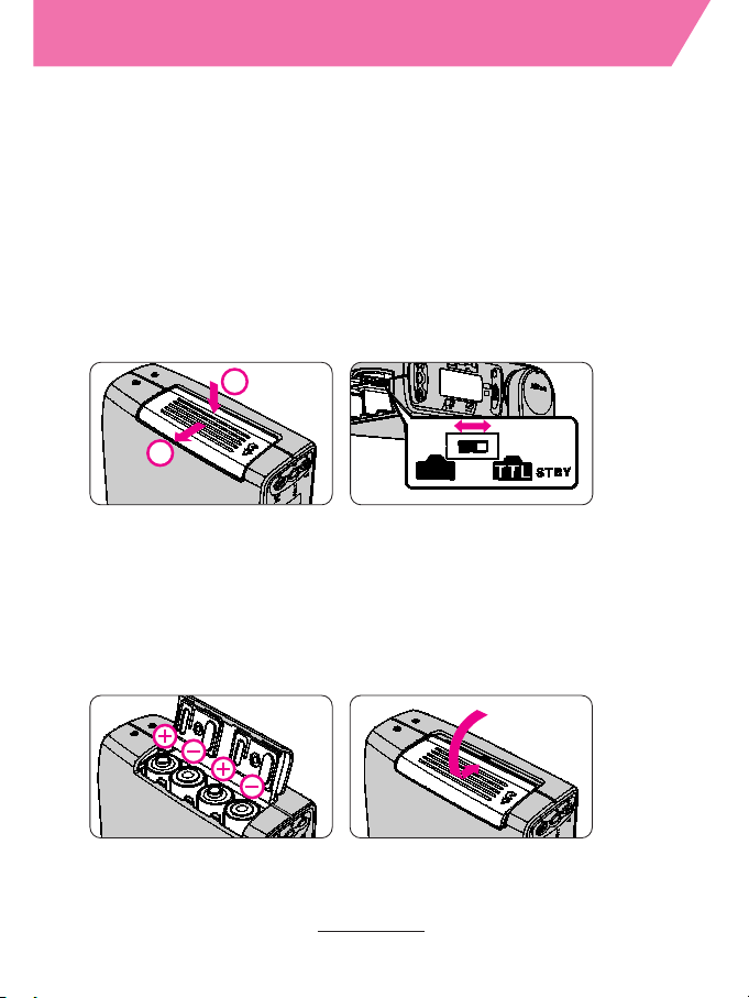
Installing batteries
11
Four penlight batteries (1.5V or lower) of any of the following
types may be used:
• AA-type alkaline-manganese (1.5V)
• AA-type lithium (1.5V)
• AA-type NiCd (rechargeable) (1.2V)
• AA-type Ni-MH (Nickel Metal Hydride) (rechargeable) (1.2V)
Note: High powered manganese batteries are not recommended
for use with this Speedlight.
See page 81 for “Notes on batteries.”
1
Open the battery chamber lid, and set the camera setting switch.
2
1
2
Install four penlight batteries and close the battery
chamber lid.
Do not mix battery brands or types, or new and old batteries.
With cameras in Groups I thru VI, be sure to set the camera
setting switch to K, and set it to ˚ for cameras in Group
VII.
See pages 12, 69 on camera setting switch.
NOTE
Replace the batteries within 30 seconds after turning OFF the
power of the SB-27 to preserve data settings.
Page 12
Standby function
(Applicable to all camera groups)
12
When both the SB-27 and the camera are not in use, the
SB-27’s power automatically shuts OFF after approx. 80
seconds in order to conserve battery power. (Standby
function)
Setting the standby function
■ Cameras in Groups I thru VI (featuring TTL Auto Flash)
Set the camera setting switch (inside the SB-27's battery
chamber) to K.
—If it is set to ˚, the standby function will not work.
To turn the SB-27’s power ON again
Lightly press the shutter release button to turn the power ON.
—Pressing the open-flash button also turns the SB-27’s power ON. In this
case, the flash does not fire. (See page 18.)
Standby function will not work when:
• Shutter speed is set at M250 or B (Bulb) (for FA and FE2)
• Shutter speed is set at M90 or B (Bulb) (for FG and Nikonos V).
• Shutter speed is set at B (bulb) (for FM3
A).
When your SB-27 is not in use or if you carry it in a bag, we
recommend setting the flash mode selector to OFF to avoid
turning the power ON accidentally.
Page 13

13
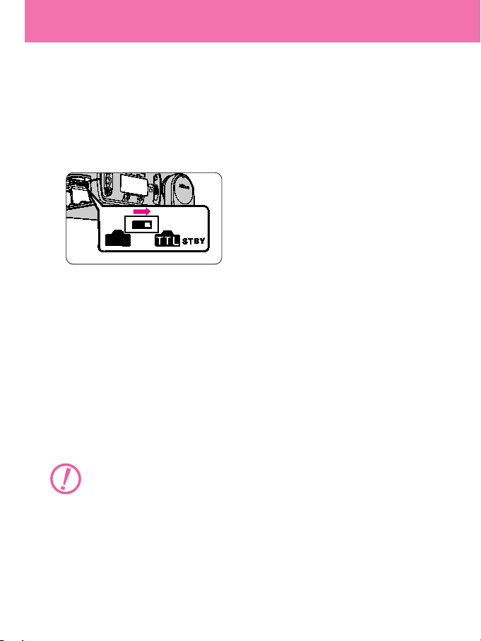
■ Cameras in Group VII (without TTL Auto Flash)
As the standby function is not available, be sure to set the camera
setting switch (inside the SB-27's battery chamber) to ˚.
NOTE
If you use the SB-27 with two cameras (one featuring TTL Auto Flash
and the other without TTL Auto Flash), we recommend setting the
camera setting switch to ˚ so that the flash mode automatically
switches to
t mode with the camera featuring TTL Auto Flash, and
to
˙ mode with the camera without TTL Auto Flash capability.
—Be sure to turn the SB-27's power OFF when the camera setting switch is
set to ˚ as the standby function will not work.
For F50-Series/N50, F-601/N6006, and F-601M
/N6000
If camera power shuts OFF with the camera setting switch (inside the
SB-27's battery chamber) set to ˚, the
t indicator in the LCD
panel changes to
˙. This is no cause for concern.
If the SB-27's flash mode selector is set to "AUTO", the
˙ indicator in
the LCD panel changes to
t enabling TTL Auto Flash operation.
Page 14
Attaching the SB-27 to the camera
14
When attaching the SB-27, make sure both the Speedlight
and the camera are turned OFF to avoid accidental firing.
1
Loosen the SB-27's mounting foot locking wheel.
2
Attach the SB-27 to the camera accessory shoe and
tighten the locking wheel.
NOTE
Loosen the mounting foot locking wheel all the way to detach
the SB-27.
With cameras equipped with a safety lock system, the mount pin is
automatically inserted into the locking hole in the camera's
accessory shoe to secure the SB-27. To detach the SB-27, loosen
the mounting foot locking wheel all the way. (See page 9.)
—A squeaky sound can be heard when loosening the mounting foot
locking wheel. This is no cause for concern.
Page 15
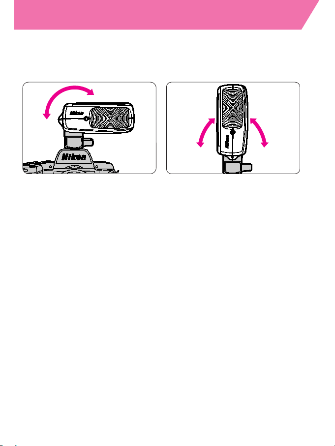
Adjusting the flash head
15
The flash head rotates from the horizontal to the vertical
position along a 180° arc. From the horizontal position,
simply tilt the flash head up 90° until it clicks into position.
Keep the flash head in the horizontal position for normal flash
shooting.
• When the flash head is set to the left as viewed by the
photographer, a shadow falls to the right of the subject, and if
the flash head is set to the right, the shadow falls to the left.
• When the flash head is set in the vertical position, the shadow
appears under the subject's chin or just behind the subject, as
the flash illuminates the subject from the top.
—This flash-head adjustment capability makes multi-directional bounce
flash operation possible. (See page 49.)
Page 16
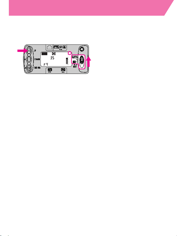
Selecting a measurement system (meters/feet)
16
Set the flash shooting distance measurement system in the
LCD panel to either meters (m) or feet (ft).
—The system is preset to meters (m) when shipped from the factory.
TTL
A
M
M
ZOOM
ISO
mm
ft m
60
30
15
7
4
2
18
9
4
2
1
0.6
Set the flash mode selector from “OFF” to “M” or “AUTO” while
holding down the “F” button and select the desired indication (m or ft).
—If you replace the batteries with the SB-27's power ON, the measurement
system returns to the default meters (m) system, even if feet (ft) had been
previously set.
Page 17
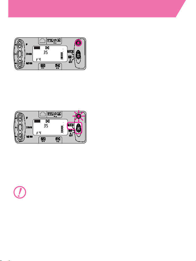
The ready-light
17
The ready-light comes ON when charging is completed.
When the SB-27 is fully charged and ready to fire, the ready-light
comes ON. Be sure to check that the ready-light is ON when
releasing the shutter.
TTL
A
M
M
ZOOM
ISO
mm
ft m
60
30
15
7
4
2
18
9
4
2
1
0.6
The ready-light blinks when flash fires at its maximum output.
In AUTO mode, if the ready-light blinks for approx. 3 seconds after
shooting, it means that the flash has fired at its maximum output
but the light may have been insufficient. (See page 40.)
—In that case, reconfirm the flash shooting distance range, aperture and
flash-to-subject distance, and if necessary, use a wider aperture or move
closer to the subject and then reshoot.
Replace batteries with a fresh set.
• Replace alkaline-manganese batteries (or lithium
batteries) if the ready-light takes more than 30 seconds
to light up.
• Recharge NiCd batteries if the ready-light takes more than
10 seconds to light up.
TTL
A
M
M
ZOOM
ISO
mm
ft m
60
30
15
7
4
2
18
9
4
2
1
0.6
Page 18

Test firing with the open-flash button
18
1
Set the flash mode selector to “M” or “AUTO”.
TTL
A
M
M
ZOOM
ISO
mm
ft m
60
30
15
7
4
2
18
9
4
2
1
0.6
The ready-light comes ON when the SB-27 is ready to fire.
2
Check if the ready-light is ON and press the open-flash
button to ensure that the SB-27 is firing properly.
TTL
A
M
M
ZOOM
ISO
mm
ft m
60
30
15
7
4
2
18
9
4
2
1
0.6
When battery power becomes weak, the ready-light takes
longer to come ON or the power may automatically shut OFF .
NOTE
Pressing the open-flash button also turns ON the SB-27 after it
has been turned OFF by the standby function. (See page 12.)
—In this case, the flash will not fire. Press the open-flash button once
more to resume normal test firing.
Page 19
Setting ISO film speed
19
The following ISO film speeds can be used in AUTO mode:
•ISO 25 to ISO 1000 for cameras in Groups I thru IV, and
F-501/N2020, F-301/N2000 cameras.
•ISO 25 to ISO 400 for cameras in Groups VI and VII, and
F-401s/N4004s and F-401/N4004 cameras.
With cameras in Groups I and II
ISO film speed is set automatically, but does not appear in the
LCD panel.
—Manual ISO film speed setting is not possible.
With cameras in Groups III thru VII
Set the ISO film speed manually as follows:
1
Press the “M” button to see the film speed indicator in
the LCD panel.
TTL
A
M
M
ZOOM
ISO
mm
ft m
60
30
15
7
4
2
18
9
4
2
1
0.6
2
Set the ISO film speed of the film loaded.
TTL
A
M
M
ZOOM
ISO
mm
ft m
60
30
15
7
4
2
18
9
4
2
1
0.6
Press the “M” button to advance the film speed setting. To
speed up the advance, keep pressing the button.
—Stop when the ISO speed of the film in use is displayed in the LCD
panel.
Page 20
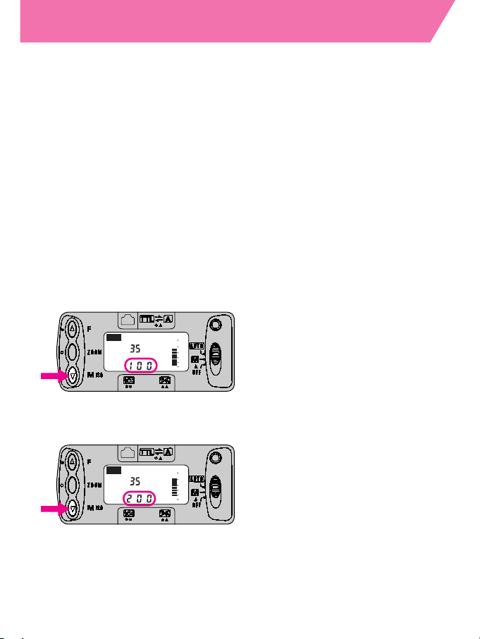
Setting zoom-head position
20
In the horizontal position, the SB-27 has four zoom-head
position settings: 24mm, 28mm, 35mm and 50mm.
Three zoom-head position settings are available in the
vertical position: 35mm, 50mm and 70mm.
—All the above stops are indicated in the LCD panel.
—Zoom-head positioning differs depending on the camera/lens
combination.
Cameras in Groups I and II with Nikkor lenses with built-in CPU
The SB-27 automatically adjusts the zoom-head position to provide
an angle of coverage that matches the focal length of the lens in
use. (Automatic zoom-head positioning)
TTL
A
M
M
ZOOM
ISO
mm
ft m
60
30
15
7
4
2
18
9
4
2
1
0.6
TTL
A
M
M
ZOOM
ISO
mm
ft m
60
30
15
7
4
2
18
9
4
2
1
0.6
—When using a Nikkor lens with built-in CPU whose focal length is below
or above the SB-27's available range, the zoom-head automatically
adjusts to the closest focal length setting.
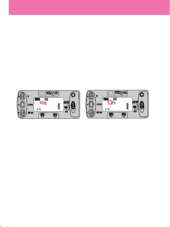
Note: Automatic zoom-head positioning is not possible if a small M
appears above the ZOOM. Press the “ZOOM” button several times
until the M disappears ➀.
NOTE
To cancel automatic zoom-head positioning and set the
position manually:
(1) Press the “ZOOM” and “M” buttons simultaneously for approx. 2
sec. until the small M above the ZOOM starts to blink ➁.
Automatic zoom-head positioning is canceled.
(2) When the small M has stopped blinking, press the “ZOOM”
button and set the desired zoom-head position manually.
When set in this way, the zoom-head position setting remains
unchanged even if the power is turned ON or OFF, or the lens is changed.
• To resume automatic zoom-head positioning, perform procedure (1)
above to make the small M above the ZOOM disappear. If the small M
is still visible, continue to press the “ZOOM”
button.
➀
Automatic zoom-head positioning is activated.
➁
Automatic zoom-head positioning is canceled.
Page 21
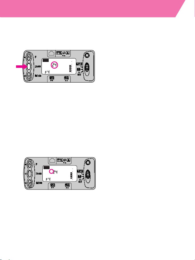
21
Other camera/lens combinations
Adjust the zoom-head position manually to provide an angle of
coverage that matches the focal length of the lens in use.
TTL
A
M
M
ZOOM
ISO
mm
ft m
60
30
15
7
4
2
18
9
4
2
1
0.6
TTL
A
M
M
ZOOM
ISO
mm
ft m
60
30
15
7
4
2
18
9
4
2
1
0.6
1
Press the “ZOOM” button to adjust the zoom-head
position.
—The indicator changes every time you press the “ZOOM” button.
When using a Zoom-Nikkor lens, set the lens at its shortest length in
order to cover the full zoom length range: (e.g., select the 28mm
setting when using a Zoom-Nikkor 28–85mm lens.)
2
Confirm that the small M above the ZOOM is displayed in
the LCD panel.
Page 22

22
Basic flash operation
This section describes which SB-27 flash
operations are available in AUTO mode for
each camera group.
See page 42 for Manual (M) flash operation.
See page 69 for non-TTL Auto Flash
with cameras in Groups I thru VI.
Automatic Balanced Fill-Flash
with TTL Multi Sensor
For details on each flash operation, refer to
the Glossary of terms on pages 83 to 88.
Page 23
Selecting a flash mode
23
For available flash operations in each camera group, consult the
table below.
Camera
Available flash operation
Flash smode Reference
group
indicator page.
・ Automatic Balanced Fill-Flash with
TTL Multi Sensor****
P. 24
I
*/**
・ Center-Weighted/ Spot Fill-Flash
・ Standard TTL Flash
・ Matrix Balanced Fill-Flash
II
*/**
・ Center-Weighted/ Spot Fill-Flash P. 26
・ Standard TTL Flash
・ Matrix Balanced Fill-Flash
III ・ Center-Weighted/ Spot Fill-Flash P. 28
・ Standard TTL Flash
IV
・ Matrix Balanced Fill-Flash
P. 30
・ Center-Weighted Fill-Flash
V
・ Programmed TTL Auto Flash
P. 32
・ Standard TTL Flash
VI
・ Standard TTL Flash P. 36
VII
***
・ Non-TTL Auto Flash R P. 38
TTL
A
M
M
ZOOM
ISO
mm
ft m
60
30
15
7
4
2
18
9
4
2
1
0.6
Flash mode indicator
Flash shooting distance
scale
Flash mode selector
Aperture indicator
“M” (M/ISO) button
*The SB-27's flash mode indicator changes every time the “M” button is pressed.
** Center-Weighted Fill-Flash/Spot Fill-Flash is not possible with F80-Series/N80-Series
and Pronea 600i/6i cameras.
***Only possible when the camera setting switch is set to ˚. (See page 13.)
Set the flash mode selector to “AUTO” and flash modes for
each camera group automatically become available.
****Automatic Balanced Fill-Flash with TTL Multi Sensor is a general term for both
3D Multi-Sensor Balanced Fill-Flash and Multi-Sensor Balanced Fill-Flash.
Page 24
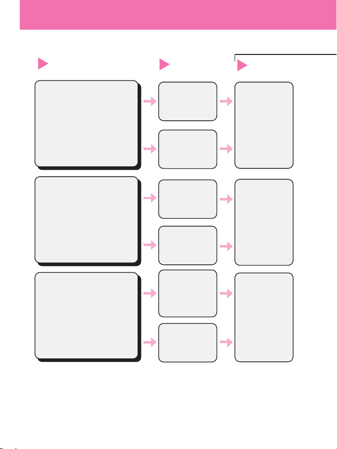
Flash operation in AUTO mode
(Cameras in
24
• Nikkor lenses with
built-in CPU
except D/G-type and AF
Nikkor lenses for the F3AF
camera
• AI-P-type Nikkor lenses
Nikkor lenses
*
5
without built-in CPU
Metering system*
2
Available flash
operation*
1
Lens in use
Camera settings
3D Multi-Sensor
*
3
Balanced Fill-Flash
tØ*
4
Multi-Sensor
*
3
Balanced Fill-Flash
tØ*
4
Standard
TTL Flash
t
Center-Weighted/
Spot Fill-Flash
tø
(except F80-Series/
N80-Series cameras)
Standard
TTL Flash
t
Desired
metering
system
CenterWeighted/Spot
Metering
1
2
3
Procedures
D- or G-type Nikkor lenses
•
With a G-type Nikkor lens attached
to F90X/N90s, F90-Series/N90 or
F70-Series/N70 cameras, the A and
M exposure modes cannot be used.
Standard TTL
Flash
t
*1 Press the “M” button to change the SB-27’s flash mode indicator.
*2 If the F5, F100, or F80-Series/N80-Series is set to Spot Metering, flash operation is
automatically set to Standard TTL Flash.
*3 3D Multi-Sensor Balanced Fill-Flash and Multi-Sensor Balanced Fill-Flash are generally
referred to as Automatic Balanced Fill-Flash with TTL Multi Sensor.
*4 When Ø appears on the LCD panel, Monitor Preflash is possible.
*5 With a non-CPU lens attached to the F80-Series/N80-Series camera, set the exposure
mode to Manual only. The camera's exposure meter cannot be used. Set and confirm the
aperture using the lens aperture ring.
Desired
metering
system
Page 25
25
Group I: F5, F100, F90X/N90s, F90-Series/N90, F80-Series/N80-Series, F70-Series/N70)
P, S*
7
A, M*
7
A, M*
7
1) Set the lens to its minimum aperture (highest f-number)
(except G-type Nikkor lenses)
1) While looking at the indicator bars, press the “F” button
to change the aperture and bring the subject within flash
shooting distance range. Next, read the aperture value.
Press the shutter release button halfway. Check the
indicator bars and the subject's distance as you rotate the
camera's command dial or lens aperture ring to determine
the aperture value.
2) Set the corresponding aperture value on the lens
aperture ring.
2) Press the shutter release button halfway and check the
flash shooting distance range in the LCD panel.
If readylight is
ON,
release
shutter.
Setting aperture and confirming flash shooting
distance range*
6
Shooting
Exposure
mode
456
*
6
With the F5’s exposure mode set to S or M, when shutter speed is set to 1/300
sec. using a custom function setting, 1/300 TTL High-Speed Sync Flash can
be selected. (For checking flash shooting distance range, see page 40.)
*
7 S: Shutter-priority auto, P: Programmed auto,
A: Aperture-priority auto, M: Manual
TTL
A
M
M
ZOOM
ISO
mm
ft m
60
30
15
7
4
2
18
9
4
2
1
0.6
TTL
A
M
M
ZOOM
ISO
mm
ft m
60
30
15
7
4
2
18
9
4
2
1
0.6
TTL
A
M
M
ZOOM
ISO
mm
ft m
60
30
15
7
4
2
18
9
4
2
1
0.6
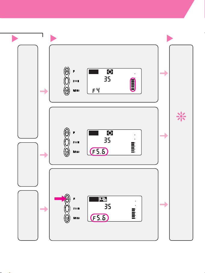
Page 26
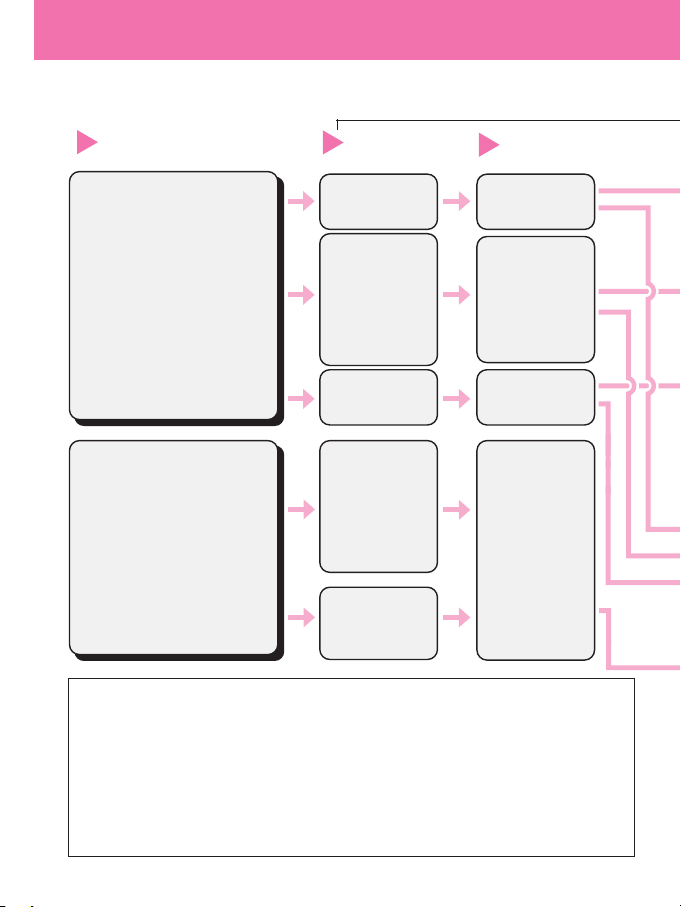
Flash operation in AUTO mode
(Cameras in
26
Nikkor lenses
with built-in CPU
With a G-type Nikkor lens
attached to F4-Series, F-801s/
N8008s, F-801/N8008 cameras,
the A and M exposure modes
cannot be used.
Nikkor lenses
without built-in CPU*
4
Matrix Metering
Matrix Balanced
Fill-Flash
tø
CenterWeighted/Spot
Metering
Desired
metering
system
CenterWeighted/Spot
Fill-Flash
tø
(except Pronea
600i/6i cameras)
Standard
TTL Flash
t
CenterWeighted/Spot
Metering
CenterWeighted/Spot
Fill-Flash
tø
(except Pronea
600i/6i cameras)
Standard
TTL Flash
t
Metering system *
2
Available flash
operation*
1
Lens in
use
Camera settings
1
2
3
Procedures
*1 Press the “M” button to change the SB-27's flash mode indicator.
*2 With an F4-Series camera set to Spot Metering, flash operation is automatically
set to Standard TTL Flash mode.
*3 S: Shutter-priority auto, P: Programmed auto, A: Aperture-priority auto, M: Manual
*4 Matrix Balanced Fill-Flash operation is only possible with F4-Series camera even
when AI-S or AI-type Nikkor lenses, Nikon Series E lenses, and lenses for the
F3AF are mounted. With a non-CPU lens attached to Pronea 600i/6i cameras, set
the exposure mode to Manual only. The camera's exposure meter cannot be
used. Set and confirm the aperture using the lens aperture ring.
*5 Center-Weighted Fill-Flash/Spot Fill-Flash is not possible with Pronea 600i/6i
cameras. Only Standard TTL Flash can be performed when the camera’s
exposure mode is set to Manual (M).
Page 27
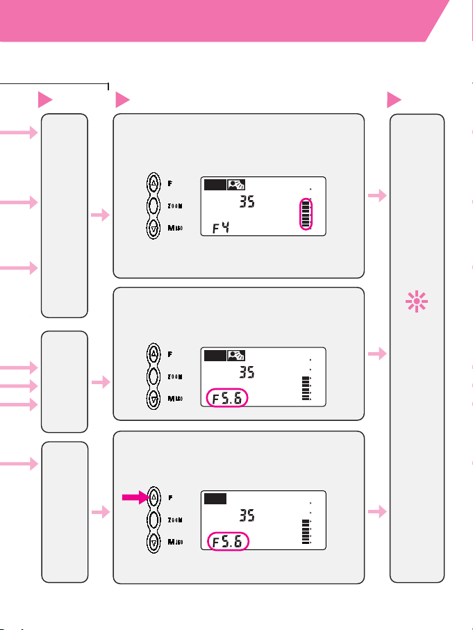
27
Group II: F4-Series, F65-Series/N65-Series, F-801s/N8008s, F-801/N8008, Pronea 600i/6i)
P, S *
3
A, M*
3
A, M*
3
Exposure
mode*
5
4
1) Set the lens to its minimum aperture (highest f-number)
(except G-type Nikkor lenses)
1) While looking at the indicator bars, press the “F”
button to change the aperture and bring the subject
within flash shooting distance range. Next, read the
aperture value.
Press the shutter release button halfway. Check the
indicator bars and the subject's distance as you rotate the
camera's command dial or lens aperture ring to determine
the aperture value.
2) Set the corresponding aperture value on the lens
aperture ring.
2) Press the shutter release button halfway and check the
shooting distance range in the LCD panel.
If readylight is
ON,
release
shutter.
Setting aperture and confirming flash shooting
distance range
Shooting
5
6
TTL
A
M
M
ZOOM
ISO
mm
ft m
60
30
15
7
4
2
18
9
4
2
1
0.6
TTL
A
M
M
ZOOM
ISO
mm
ft m
60
30
15
7
4
2
18
9
4
2
1
0.6
TTL
A
M
M
ZOOM
ISO
mm
ft m
60
30
15
7
4
2
18
9
4
2
1
0.6
*6 For Pronea 600i/6i.
Page 28
28
Flash operation in AUTO mode (Cameras in
Procedures
Nikkor lenses*
1
with built-in CPU
Nikkor lenses
without built-in
CPU
Matrix Balanced
Fill-Flash
t
Desired
metering
system
CenterWeighted/Spot
Fill-Flash
t
Standard TTL
Flash
t
tø
t
CenterWeighted/
Spot
Metering
*
2
CenterWeighted/Spot
Fill-Flash
t
CenterWeighted/
Spot
Metering
*
2
Standard TTL
Flash
t
Flash mode and metering
system
Available flash
operation
Lens in use
Camera settings
1
2
3
tø
Matrix
Metering
tø
t
CenterWeighted/
Spot Metering
*
1
G-type Nikkor lenses cannot be used with an
F-601/N6006 camera.
*
2
Spot Metering is only available with F-601/N6006.
Page 29

29
Group III: F-601/N6006, F-601M/N6000)
P, S *
A, M *
1) Set the lens to its minimum aperture (highest
f-number)(except G-type Nikkor lenses).
2) Press the shutter release button halfway and read the
controlled aperture in the camera's viewfinder.
3) Press the “F” button to set the corresponding
aperture in the LCD panel, then confirm the flash
shooting distance range.
1) While looking at the indicator bars, press the "F"
button to change the aperture and bring the subject
within flash shooting distance range. Next, read the
aperture value.
2) Set the corresponding aperture value on the lens
aperture ring.
If readylight is ON,
release
shutter.
Setting aperture and confirming flash
shooting distance range
Shooting
Exposure
mode
4
5
6
* S: Shutter-priority auto, P: Programmed auto,
A: Aperture-priority auto, M: Manual
TTL
A
M
M
ZOOM
ISO
mm
ft m
60
30
15
7
4
2
18
9
4
2
1
0.6
TTL
A
M
M
ZOOM
ISO
mm
ft m
60
30
15
7
4
2
18
9
4
2
1
0.6
Page 30

Flash operation in AUTO mode (Cameras in
30
Procedures
Nikkor lenses
with built-in CPU
Nikkor lenses
without built-in CPU
Matrix
Balanced
Fill-Flash
t
Manual (M)
CenterWeighted
Fill-Flash
t
Manual (M)
CenterWeighted
Fill-Flash
t
Camera's
exposure mode
Available flash
operation
Lens in use
1
2
3
• Programmed
auto (P)
•
Shutter-priority
auto (S)
Aperturepriority auto
(A)
Page 31

31
Group IV: F60-Series/N60, F50-Series/N50, F-401x/N5005)
1)
Set the lens to its minimum aperture (highest f-number) (except G-type Nikkor lenses).
2) While looking at the indicator bars, press the “F” button to change the
aperture and bring the subject within flash shooting distance range.
Next, read the aperture value
3) Set the corresponding aperture in the F60-Series/N60 or F50-Series/N50's
LCD panel (for F-401x/N5005, rotate the aperture dial).
1) While looking at the indicator bars, press the “F” button to change the
aperture and bring the subject within flash shooting distance range.
Next, read the aperture value.
2) Set the corresponding aperture on the camera.
2)
With an F60-Series/N60 or F50-Series/N50 camera in the ADVANCED mode, set
the aperture appearing in the camera’s viewfinder on the SB-27’s LCD panel by
pressing the SB-27’s “F” button. Then confirm the flash shooting distance range.
If readylight is
ON,
release
shutter.
Setting aperture and confirming flash shooting
distance range
Shooting
4
5
1) Set the lens to its minimum aperture (highest f-number) (except G-type
Nikkor lenses).
F50-
Flash shooting conditions Sunny
Cloudy day or
Indoors
Series
(ISO 100) day
in shadows
/N50
Aperture setting on SB-27 *
f/8 f/5.6 f/4
Flashshootingconditions
Backlitby
Sunny Cloudyday Indoors
(ISO100)
thesun day
or
inshadows
F-401X/
AperturesettingonSB-27
f/16 f/8 f/5.6 f/5.6
N5005
Usableshutterspeedin
1/125sec 1/30sec
shutter-priorityautomode**
**Aperture is automatically selected by the camera.
*
With an F50-Series/N50 camera in the SIMPLE mode, select the aperture from
the table above and set the same aperture on the SB-27’s LCD panel by pressing
the SB-27’s “F” button. Then confirm the flash shooting distance range.
TTL
A
M
M
ZOOM
ISO
mm
ft m
60
30
15
7
4
2
18
9
4
2
1
0.6
Page 32

Flash operation in AUTO mode (Cameras in
32
Procedures
• Aperture-priority
auto (A)
• Manual (M)
Standard TTL
Flash
t
Camera's
exposure mode
Available flash
operation
Lens
in use
1
2
3
• Nikkor lenses with
built-in CPU*
• Nikkor lenses for F3AF
• AI-S-type Nikkor lenses
• AI-type Nikkor lenses
• Nikon Series E lenses
Programmed
TTL Auto Flash
t
Standard TTL
Flash
t
• Aperture-priority
auto (A)
• Manual (M)
Programmed
auto (P)
Other Nikkor lenses
*G-type Nikkor lenses
cannot be used.
Page 33

33
Group V: F-501/N2020, F-301/N2000)
1) Set the lens to its minimum aperture (highest f-number).
1) While looking at the indicator bars, press the “F” button to change
the aperture and bring the subject within flash shooting distance
range. Next, read the aperture value.
2) Set the corresponding aperture value on the lens aperture ring.
2) Read the suggested aperture for the film in use in the table below,
press the "F" button to set the corresponding aperture in the LCD
panel, then confirm the flash shooting distance range.
If readylight is
ON,
release
shutter.
Setting aperture and confirming flash shooting
distance range
Shooting
4
5
ISO film speed 25 50 100 200 400 800
Aperture f/2.8 f/4 f/5.6 f/8 f/11 f/16
TTL
A
M
M
ZOOM
ISO
mm
ft m
60
30
15
7
4
2
18
9
4
2
1
0.6
TTL
A
M
M
ZOOM
ISO
mm
ft m
60
30
15
7
4
2
18
9
4
2
1
0.6
Page 34

Flash operation in AUTO mode (Cameras in
34
Procedures
Nikkor lenses
with built-in CPU
Nikkor lenses
without built-in CPU
Programmed
TTL Auto
Flash
t
Standard TTL
Flash
t
Manual (M)
Standard TTL
Flash
t
Camera's
exposure mode
Available flash
operation
Lens in use
1
2
3
• Programmed
auto (P)
• Shutter-priority
auto (S)
• Aperturepriority
auto (A)
• Manual (M)
Page 35

35
Group V: F-401s/N4004s, F-401/N4004)
Flashshooting
Backlitbythesun
Sunny
Cloudydayor
Indoors
conditions day inshadows
Aperture(ISO100)
f/16 f/8 f/5.6 f/5.6
Usableshutterspeed
1/125sec 1/30sec
1)
Set the lens to its minimum aperture (highest f-number) (except G-type Nikkor lenses).
1) Set the lens to its minimum aperture (highest f-number) (except G-type
Nikkor lenses).
2) While looking at the indicator bars, press the “F” button to change the
aperture and bring the subject within flash shooting distance range.
Next, read the aperture value.
1) While looking at the indicator bars, press the “F” button to change the
aperture and bring the subject within flash shooting distance range.
Next, read the aperture value.
2) Set the corresponding aperture value on the lens aperture ring.
2) Read the aperture in the table below, and press the “F” button to set the
corresponding aperture in the LCD panel, then confirm the flash
shooting distance range.
If readylight is
ON,
release
shutter.
Setting aperture and confirming flash shooting
distance range
Shooting
4
5
*In shutter-priority auto (S) mode, aperture is automatically
selected by the camera.
3) Set the corresponding aperture value on the camera aperture dial.
TTL
A
M
M
ZOOM
ISO
mm
ft m
60
30
15
7
4
2
18
9
4
2
1
0.6
Page 36

Flash operation in AUTO mode (Cameras in
36
Procedures
Nikkor lenses with built-in CPU*
Nikkor lenses without built-in CPU
Standard TTL
Flash
t
Available flash
operation
Lens in use
1
2
Do not use the SB-27 for underwater photography.
*G-type Nikkor lenses cannot be used.
Page 37

37
Group VI: FM3A,FA, FE2, FG, Nikonos V)
1) While looking at the indicator bars,
press the “F” button to change the
aperture and bring the subject within
flash shooting distance range. Next,
read the aperture value.
2) Set the corresponding aperture value
on the lens aperture ring.
If readylight is
ON,
release
shutter.
Setting aperture and confirming
flash shooting distance range
Shooting
Camera's
exposure mode
3
4
5
Aperture-priority
auto (A) *
1
Manual (M)*
2
*1 In this exposure mode, shutter speed is automatically set to 1/250
sec. (for FM3
A, FA, FE2), and 1/90 sec. (for FG, Nikonos V).
*2
Standard TTL Flash is not possible if the shutter speed is set to
M250 or B (bulb) (for FA, FE2), and M90 or B (Bulb) (for FG, Nikonos V).
TTL
A
M
M
ZOOM
ISO
mm
ft m
60
30
15
7
4
2
18
9
4
2
1
0.6
Page 38

38
With cameras in Group VII, be sure to set the camera setting
switch (inside the SB-27's battery chamber) to ˚, and
choose “AUTO” (in the flash mode selector); the flash mode
is automatically set to Non-TTL Auto Flash.
—In non-TTL Auto Flash mode, flash mode indicator ˙ appears in the
SB-27's LCD panel.
Procedures
Nikkor lenses with built-in CPU*
Nikkor lenses without built-in CPU
Non-TTL Auto
Flash
˙
Available flash
operation
Lens in use
1
2
Flash operation in AUTO mode (Cameras in Group VII:
NOTE
•
Set the lens to the same aperture value as in the SB-27 to obtain
a correct exposure.
•
A usable aperture value appears in the SB-27's LCD panel
whenever you press the “F” button.
*G-type Nikkor lenses cannot be used.
Page 39

39
1) While looking at the indicator bars, press
the “F” button to change the aperture and
bring the subject within flash shooting
distance range. Next, read the aperture
value.
2) Set the corresponding aperture value on
the lens aperture ring.
If readylight is
ON,
release
shutter.
Setting aperture and confirming
flash shooting distance range
Shooting
Camera's
exposure mode
3
4
5
• Aperture-priority
auto (A)
• Manual (M)
F3-Series, F55-Series/N55-Series, New FM2, FM10, FE10)
TTL
A
M
M
ZOOM
ISO
mm
ft m
60
30
15
7
4
2
18
9
4
2
1
0.6
Page 40

If the ready-light blinks after shooting
40
The ready-lights in the SB-27
and the camera blink for approx.
3 seconds after shooting to
signal that the flash has fired at
full output but the light may have
been insufficient.
—When using the SB-27 with cameras in
Group I, the underexposure indicator ÷ blinks in the SB-27's LCD panel
and the amount of underexposure is indicated.
TTL
A
M
M
ZOOM
ISO
mm
ft m
60
30
15
7
4
2
18
9
4
2
1
0.6
Reshooting
• Reconfirm flash-to-subject distance and flash shooting distance
range when shooting in programmed auto (P) or shutter-priority auto
(S) exposure mode, or choose aperture-priority auto (A) or manual
(M) exposure mode. Select an aperture that will allow you to bring
the subject within flash shooting distance range.
Flash shooting distance range in 1/300 TTL High-Speed Sync
Flash operation (F5 only)
Flash shooting distance range (far side) cannot be read from the
indicator bars on the SB-27 in AUTO flash mode.
In such a case, use the following “Guide number” table and equation
for calculating the shooting distance according to each zoom-head
position.
Guide number (at ISO 100 for m/ft)
Zoom head position 24mm 28mm 35mm 50mm
Guide number 11/36 12/39 14/46 16/52
Guide number
D (flash shooting distance) =
f/stop (aperture)
For example, when shooting with ISO 100 film, at a 35mm zoom-head
position and an aperture of f/5.6:
D=14/5.6 = 2.5 (far side) [measured in meters]
You can read a shooting distance (near side) of 0.6m from the SB-27’s
indicator bars. Therefore, the flash shooting distance ranges from
0.6m to 2.5m.
For films other than ISO 100, multiply the figures in the table above by
the factors shown below.
ISO film speed 25 50 200 400 800
Factor x0.5 x0.71 x1.4 x2 x2.8
Page 41

41
Advanced flash
operation
This section describes
advanced flash shooting applications
with the SB-27 Speedlight.
Bounce flash
Multiple flash
Page 42

Flash operation in Manual (M) mode (For
42
With the SB-27's flash mode selector set to “M,” light output
can be manually controlled.
—Indicator bar “¡” in the LCD panel shows the approximate flash shooting
distance range. To determine the correct aperture value, see page 46 on
“Guide numbers for determining the correct aperture.”
1
Set the camera's exposure mode to aperture-priority
auto (A) or manual (M).
ISO
SLOW
REAR
S
2
Set the SB-27's flash mode selector to “M”.
TTL
A
M
M
ZOOM
ISO
mm
ft m
60
30
15
7
4
2
18
9
4
2
1
0.6
In Manual (M) mode, confirm that the ƒ indicator appears in
the LCD panel.
F90X/N90s LCD panel shown
Page 43

43
cameras in all groups)
3
Press the “M” button to choose the desired light output.
TTL
A
M
M
ZOOM
ISO
mm
ft m
60
30
15
7
4
2
18
9
4
2
1
0.6
You can select light output settings ranging from full power (1/1)
to one-sixteenth (1/16). LCD indicators change as follows:
1/1 → 1/2 → 1/4 → 1/8 → 1/16.
4
Setting the aperture on both the SB-27 and the camera
Rotate the camera's command dial or lens aperture dial; the
indicator bar “¡” in the LCD panel changes. Before shooting,
make sure your subject is within flash shooting distance
range.
• Aperture value can be set by rotating the sub-command dial
(F5 only).
Cameras in Groups I and II with Nikkor lenses with built-in CPU
TTL
A
M
M
ZOOM
ISO
mm
ft m
60
30
15
7
4
2
18
9
4
2
1
0.6
Page 44

Flash operation in Manual (M) mode (For cameras
44
5
Confirm that the ready-light is ON, then fully depress the
shutter release button to fire the flash.
TTL
A
M
M
ZOOM
ISO
mm
ft m
60
30
15
7
4
2
18
9
4
2
1
0.6
NOTE
Manual light output control and aperture selection:
• To extend the flash shooting distance range, select the 1/1 light
output setting or set the lens to a larger aperture (lower f-number).
To reduce the flash shooting distance range, select the 1/16 light
output setting or set the lens to a smaller aperture (higher fnumber).
• To ensure sharpness in both background and foreground, set the
lens to a smaller aperture (higher f-number), and select a larger
light output setting (closer to 1/1).
• To shorten flash recycling time, select a much smaller light output
setting (closer to 1/16) and set a larger aperture (lower f-number).
Other camera/lens combinations
1) While looking at the indicator bar “¡”, press the “F” button to
change the aperture and bring the subject within flash shooting
distance range. Next, read the aperture value.
2) Set the corresponding value on the lens aperture ring or on the
camera.
TTL
A
M
M
ZOOM
ISO
mm
ft m
60
30
15
7
4
2
18
9
4
2
1
0.6
Page 45

45
in all groups)
Synchronization in continuous shooting
The SB-27 is able to recycle fast enough to synchronize with a
motor-driven camera firing continuously up to 15 flashes per
second. It is possible to take up to four full flash pictures in rapid
succession at a light output ranging from 1/8 to 1/16 (using the
SB-27’s internal batteries) in Manual (M) Flash mode.
Number of continuous flash (frames) in Manual (M) Flash mode
Light output
Power source
1/8 1/16
AA-type alkaline-manganese
48
(four sets) inside the SB-27
Optional external power source
SD-7 + AA-type alkaline-manganese 6 10
(four sets) inside the SB-27
Optional external power source
SD-8/8A + AA-type alkaline-manganese
510
(four sets) inside the SB-27
SB-27's light output Max. number of flashes
AUTO and Manual (M) mode at 1/1 or 1/2
15
light output
Manual (M) mode at 1/4, 1/8 or 1/16 light output 40
Note: The maximum number of flashes may vary with the type of battery
and the ambient temperature.
Allow the Speedlight to cool off for at least 10 minutes after
continuous firing (see the table below). Overuse generates
heat that could shorten the life of the Speedlight.
Safety range in continuous firing
We recommend letting the flash unit cool off after any level of intensive use.
Page 46

Guide numbers for determining correct aperture
46
The “guide number” represents the amount of light
generated by the flash. With the SB-27 in Manual (M) Flash
mode, you can calculate a correct aperture (f/stop) value by
using the following equation and the “Guide number” table.
—For Guide numbers in 1/300 TTL High-Speed Sync Flash
operation with the F5 camera, see page 40.
To calculate a correct aperture:
f/stop (aperture)=
guide number
flash-to-subject distance (m)
To calculate the shooting distance:
flash-to-subject distance (m)=
guide number
f/stop (aperture)
Guide number (at ISO 100: for m/ft) (at 20˚C/68˚F)
Zoom-head position
Light
24mm
28mm
35mm 50mm
Output
(normal)
1/1 (full) 25/82 27/89 30/98 34/112
1/2 17.7/58 19/62 21.2/69 24/79
1/4 12.5/41 13.5/44 15/49 17/56
1/8 8.8/29 9.5/31 10.5/34 12/39
1/16 6.2/20 6.7/22 7.4/24 8.5/28
The guide number varies with the film speed. For films other than ISO 100,
multiply the above figures by the factors shown in the table below.
Adjustment factors for other ISO film speeds
ISO film speed 25 50 200 400 800 1600
Factor × 0.5 × 0.71 × 1.4 × 2 × 2.8 × 4
For example, when shooting a subject under the following conditions,
—Light output: 1/1 (full),
—Flash mode: Manual (M) ,
—Film speed: ISO 400,
—Zoom-head position: 35mm,
you will obtain a guide number of 60 (30 × 2) using the above table.
Page 47

47
Autofocus flash operation in dim light
(For AF SLR cameras only)
Nikon AF SLR cameras using AF Nikkor lenses can
autofocus in light as dim as a single candle. When ambient
light is insufficient for autofocus operation, the
SB-27's AF assist illuminator LED automatically turns ON to
give contrast to dark subjects, enabling the camera's
autofocus system to function when the shutter release
button is pressed halfway.
Take care not to block the AF assist illuminator LED.
—The AF assist illuminator LED goes out as soon as the subject has been
correctly focused.
• No AF assist illuminator LED lights up if the F5’s, F100’s, F80-Series/
N80-Series’ or F65-Series/N65-Series’ central focus area is not selected.
Be sure to select the central focus area.
Page 48

Autofocus flash operation in dim light
(For AF SLR camera only)
48
Conditions for autofocus flash operation with the
AF assist illuminator LED
1) The subject must be sufficiently dark to activate the autofocus
assist illuminator LED.
Please note that AF assisted autofocus range extends from
1m (3.3 ft.) to 5m (16.4 ft.) at 20˚C (68˚F).
2) AF Nikkor lenses must be used.
Using AF Nikkor lenses, SB-27's focal length coverage ranges
from 24mm (35mm for F-501/N2020) to 105 mm.
Other AF Nikkor lenses may also be used depending on shooting
conditions. Be sure to take a few trial shots first.
3) The camera's autofocus mode should normally be set to Single
Servo AF (S).
4) Focus lock is not in use.
5) The ready-light is ON.
If the ready-light becomes dim or blinks after the AF assist
illuminator LED lights up, replace the SB-27's batteries with a
fresh set.
*If the AF assist illuminator LED comes ON but no in-focus indicator
appears in the camera's viewfinder with the shutter release button pressed
halfway, the subject is beyond autofocus distance range. Set the focus
mode to "Manual" and focus manually on the clear matte field.
Page 49

Bounce flash operation
(For cameras in all groups)
49
Direct flash causes harsh, unattractive shadows to appear
on the faces of subjects in front of a wall. By bouncing the
light off the ceiling or walls, you can soften the shadows and
produce more natural portraits.
The flash head rotates from the horizontal to the vertical position
along a 180° arc.
Normal flash shooting using
direct flash
Bounce flash shooting using
diffused light
Vertically bounced light
The SB-27 comes with a built-in diffuser card, useful for
highlighting a subject's eyes during bounce flash operation.
(See page 53.)
Built-in diffuser card
Page 50

50
Bounce flash operation (Applicable to all camera groups)
Notes on taking pictures with vertical bounce flash
The settings of the built-in bounce flash adapter and the diffuser
card vary depending on the focal length of the lens in use.
Nikkor lenses 35mm and longer
Set the built-in bounce flash adapter as shown.
—When set as above, you cannot use Nikkor lenses wider than 35mm.
(See the illustration [center] on the seal affixed to the bounce flash
adapter.)
Also set the diffuser card when you want to create a "catchlight" to
highlight the subject's eyes. (See page 53.)
Nikkor lenses 24mm and longer
Set both the built-in bounce flash adapter and diffuser card as shown.
—Even when set as above, you cannot use Nikkor lenses wider than
24mm. (See the illustration [bottom] on the seal affixed to the bounce
flash adapter.)
Always set the diffuser card whether you wish to create a
"catchlight" or not. (See page 53.)
Notes on taking pictures with flash in vertical position
• With the built-in bounce flash adapter mounted, use Nikkor
lenses 50mm or longer.
• With both the built-in bounce flash adapter and the diffuser card
mounted, use Nikkor lenses 35mm or longer.
Page 51

51
1
Set the camera's exposure mode to aperture-priority
auto (A) or manual (M).
With bounce flash operation, there is 2 to 3 f/stops less light
available than in normal flash operation. We recommend that
you select wider aperture (lowest possible f-number) and
bracket to ensure correct exposure.
2
Set the SB-27's flash mode selector to "AUTO".
TTL
A
M
M
ZOOM
ISO
mm
ft m
60
30
15
7
4
2
18
9
4
2
1
0.6
3
Check the reflective surface and adjust flash head direction.
NOTE
Choose a reflective surface with a high reflection factor such
as a white wall for bouncing the light off.
In color photography, only use bounce against white reflective
surfaces. Otherwise, color photographs will come out with an
unnatural color cast similar to that of the reflective surface.
Make sure you set the camera setting switch to K with
cameras in Groups I thru VI, and to ˚ with cameras in Group
VII. (Do not select the K setting with cameras in Group VII.)
Procedures for bounce flash operation
Page 52

52
Bounce flash operation (Applicable to all camera groups)
4
Set up the built-in bounce flash adapter.
2
1
Pull out the bounce flash adapter ➀, then raise it approx. 45° ➁.
(The bounce flash indicator appears in the LCD panel.)
—Do not force the bounce flash adapter.
5
Confirm that the ready-light is ON, then release the
shutter to fire the flash.
TTL
A
M
ISO
ft m
60
30
15
7
4
2
18
9
4
2
1
0.6
If the ready-light blinks for 3 seconds after shooting, reconfirm
the flash shooting distance range or select a wider aperture,
and then reshoot.
—In bounce flash operation, no indicator bars appear in the LCD
panel. (The SB-27 no longer indicates the correct relationship
between aperture and flash shooting distance range.)
Page 53

53
To set up the diffuser card:
1
Set the built-in bounce flash adapter.
2
Unfold the built-in diffuser card.
Highlight your subject’s eyes using bounced flash
The SB-27 comes with a built-in bounce flash adapter for bouncing
diffused light off the ceiling. The diffuser card brightens shadows
caused by top-lighting or bouncing flash, making your subject’s
eyes appear more vibrant.
Page 54

54
Close-up flash operation in AUTO mode
(Cameras in Groups I thru VI)
The SB-27 incorporates a built-in diffuser card which
diffuses light, enabling you to take close-up flash pictures
from 0.3m (1 ft.), softening harsh shadows and producing
natural-looking results with the SB-27 mounted on the
camera.
Two methods are possible:
(1) Mounting the SB-27 on the camera (See page 56.)
(2) Connecting the SB-27 to the camera using an optional TTL
Remote Cord (See page 59.)
—With a very light or dark-toned subject, you may not get a correct
exposure due to the subject's reflection factor. See page 60 on
"Exposure compensation for flash photography" and page 69 on
"Setting Forced TTL and Forced A modes" to ensure correct exposure.
Page 55

55
Notes on close-up flash operation
Take note of the following points when shooting close-ups with the
SB-27 mounted on the camera.
Usable lenses are limited.
Avoid using any Nikkor lens whose actual length is shorter than
that of the built-in bounce flash adapter ( line in the illustration).
If the lens is too short, the incident light falling on the lens reflects
on the built-in bounce flash adapter causing a flare effect on the
film. (See the illustration [top] on the seal affixed to the bounce
flash adapter.
Other notes
In close-up flash operation, we recommend taking trial shots first
because pictures may be slightly dim or a shadow may appear
around the edge of the frame depending on the lens in use or the
flash-to-subject distance.
Page 56

56
3
Pull out the built-in bounce flash adapter.
Pull out the bounce flash adapter all the way and tilt it
downward approx. 45°. (The bounce flash indicator appears
in the LCD panel.)
—Do not force the bounce flash adapter.
Close-up flash operation in AUTO mode (Cameras in Groups I
NOTE
If the bounce flash adapter comes off and you cannot set the
zoom-head position corresponding to the lens in use.
Simultaneously press the "ZOOM" and "F" buttons for approx. 4 seconds.
The zoom-head position indicator then blinks, and you can proceed with
automatic or manual zoom-head setting. Four stops (24mm, 28mm, 35mm
and 50mm) are available with the flash-head in the horizontal position, and
3 stops (35mm, 50mm and 70mm) with the flash-head in the vertical
position, depending on the camera/lens combination. (See page 20.)
1
Set the camera's exposure mode to aperture-priority
auto (A) or manual (M).
—For cameras in Group I to VI, in addition to selecting Aperture
Priority or Manual, the Close Up Program within the Vari-Programs
can also be used.
Procedures (with the SB-27 mounted on the camera)
TTL
A
M
M
ZOOM
ISO
mm
ft m
60
30
15
7
4
2
18
9
4
2
1
0.6
2
Set the SB-27's flash mode selector to “AUTO”.
Page 57

57
4
Set up the diffuser card as shown.
The SB-27's built-in diffuser card is effective for close-up flash
operation from 0.3m (1 ft).
—Avoid using the built-in diffuser card for close-up flash operation in non-TTL Auto
Flash mode. (You cannot obtain a correct exposure if the diffuser card is set.)
thru VI)
6
Confirm that the ready-light is ON, then release the shutter to fire the flash.
TTL
A
M
ISO
ft m
60
30
15
7
4
2
18
9
4
2
1
0.6
If the ready-light blinks for 3 seconds after shooting, see page 40.
f/stop≧
1
=2*
0.5
For example, with a subject located 0.5m (1.6 ft) away using ISO 100 film
and a bounce flash adapter, this is how you would calculate the aperture:
* An aperture of f/2 is suggested. We recommend using the smallest possible aperture ( f/2.8 or f/4).
5
Set the camera’s aperture based on the following equation and table.
f/stop ≧
coefficient
flash-to-subjectdistance(m)
ISO film speed and coefficient
ISO film speed 100 or lower 125–400 500 or higher
Coefficient* 1 (3.3) 2 (6.6) 2.8 (9.2)
*Numbers in parentheses ( ) represent coefficient for foot measurement.
Page 58

Close-up flash operation in AUTO mode (Cameras in
58
When you want to ensure sufficient illumination, or illuminate
your subject from the side or the back, detach the SB-27
from the camera and use an optional TTL Remote Cord.
Close-up flash operation using a TTL Remote Cord
1
Connect the SB-27 to the camera using a TTL
Remote Cord.
—Use optional TTL Remote Cord SC-24 when connecting the SB-27 to
an F4-Series camera fitted with a High-Magnification Finder (DW-20
or DW-21).
—Use optional TTL Remote Cord SC-17 when connecting the SB-27 to
other cameras with an ISO type hot shoe.
2
After first setting the camera’s exposure mode to A or M,
set the SB-27’s flash mode selector to “AUTO.”
3
Position the SB-27 properly and adjust the angle.
—Be sure to position the SB-27 and adjust the angle so as to
sufficiently illuminate the subject.
Page 59

59
Groups I thru VI)
5
Confirm that the ready-light is ON, then release the
shutter to fire the flash.
In 3D Multi-Sensor Balanced Fill-Flash operation with cameras in Group I,
press the "M" button to change the flash mode indicator from tØ to
t in order to cancel Monitor Preflash*. This will avoid exposure errors
when removing the SB-27 from the camera. (See page 63.)
*See page 86 on Monitor Preflash.
f/stop≧
4
=8*
0.5
For example, with a subject located 0.5m (1.6 ft) away using ISO 100
film, this is how you would calculate the aperture:
* An aperture of f/8 is suggested. We recommend using the smallest
possible aperture ( f/11 or f/16).
With a very light or dark-toned subject, you may not obtain a
correct exposure due to the subject's reflection factor. Use
exposure compensation to ensure correct exposure.
(See pages 60, 69.)
f/stop ≧
coefficient
flash-to-subjectdistance(m)
ISO film speed and coefficient
ISO film speed 100 or lower 125–400 500 or higher
Coefficient* 4 (14) 8 (26) 11 (36)
*Numbers in parentheses ( ) represent coefficient for foot measurement.
4
Set the camera’s aperture based on the following equation and table.
Page 60

Exposure compensation for flash photography
60
"Plus" compensation "Minus" compensation
In AUTO (TTL Auto Flash) mode, difficult scenes, such as
bright objects in the background, or a main subject at the
edge of the frame, may cause overexposure or
underexposure. You can manually adjust the exposure
(compensate the Speedlight's light output level in TTL Auto
Flash mode) to make the picture lighter or darker.
When the background is extremely bright, use “+”
compensation and when the background is very dark, use
“–” compensation.
—In Automatic Balanced Fill-Flash with TTL Multi Sensor operation using
cameras in Group I, the camera automatically compensates exposure
according to the shooting conditions. Flash light output level
compensation is not necessary inside the normal flash shooting distance
range.
—Make sure that the flash shooting distance range shifts when the
exposure is compensated. Check that the subject is within flash shooting
distance range after compensation.
Page 61

61
(Cameras in Groups I thru III)
Setting exposure compensation for flash
The setting method varies depending on the camera.
Cameras in Groups I and II
Cameras with EV compensation control capability allow you to
compensate flash exposure on either the SB-27 or the camera (or
both.) If you use both controls, exposure is modified by the sum
total of both exposure compensation values.
For example, with a compensation of +1EV on the SB-27 and +1EV
on the camera, the background will be +1EV and the flash output
will be +2EV. Keep in mind that the SB-27's exposure compensation value indicator will not display the sum total of both
compensation values. Only the compensation value set on the
SB-27 is displayed.
Setting exposure compensation on the SB-27
TTL
A
M
M
ZOOM
ISO
mm
ft m
60
30
15
7
4
2
18
9
4
2
1
0.6
1) Simultaneously press the “F” and “M” buttons .
2) Confirm the exposure compensation value indicator in the LCD
panel appears after blinking for approx. 4 sec.
3) To set the desired exposure compensation, press the “F” button
to increase the compensation value and press the “M” button to
decrease the compensation value.
4) The exposure compensation indicators ¿ and exposure
compensation value come on.
Exposure compensation is possible in 1/3 EV steps. (“–” side:
from –0.3 to –3.0 EV, and “+” side: from +0.3 to +1.0 EV) .
Page 62

62
Exposure compensation for flash photography
(Cameras in Groups I thru III)
TTL
A
M
M
ZOOM
ISO
mm
ft m
60
30
15
7
4
2
18
9
4
2
1
0.6
Canceling exposure compensation
Flash exposure compensation cannot be canceled by turning the
power OFF. To cancel, reset the exposure compensation amount
to 0.0 following the same steps outlined on page 61.
Cameras in Group III
Use the camera's EV compensation control function to make
exposure compensation.
—For further details, refer to the camera's Instruction Manual.
With Group III cameras, the SB-27's LCD panel does not show the
correct flash shooting distance range or the correct compensation
amount. Use the following chart as a guide for obtaining the
correct flash shooting distance range.
25 50 100 200 400 800 1600
+ー
32 40 64 80
125 160 250 320 500 640 1000 1250
For example, with ISO 100 film, if you want to compensate by +1EV
on the camera, set the ISO film speed to 50 on the SB-27’s LCD
panel; if you want to compensate by –2EV, set the ISO film speed
to 400.
NOTE
With exposure compensation set on the camera, the SB-27’s light
output is automatically controlled for correct background
illumination.
Page 63

63
When you wish to eliminate harsh shadows produced by a
single flash unit or if you want to extend light up into the
background, use more than one flash unit.
For multiple flash operation with the SB-27, both TTL Auto
and Manual (M) Flash modes are available.
—Multiple flash operation in TTL Auto Flash mode is possible with cameras
in Groups I thru VI and F3-Series cameras. Multiple flash operation in
Manual (M) Flash mode is possible with cameras in all groups.
—In multiple flash operation in either TTL or manual mode, first decide
which will be the main (Master) unit and which the secondary (Slave)
unit(s). For example, to eliminate shadows, adjust the lighting ratio so
that master unit illumination is greater than secondary unit illumination.
Flash shooting with one flash unit Flash shooting with more than one unit
Multiple flash operation—using more than one Speedlight
(Applicable to all camera groups)
NOTE
Cameras in Group I
With the SB-27 as the master flash set to 3D Multi-Sensor Balanced FillFlash, you may not be able to obtain correct exposure because of a
change in lighting conditions between initial Monitor Preflash* and actual
flash firings. First cancel Monitor Preflash using one of the following
methods:
• Set the built-in wide flash adapter to the upper or left direction.
• Set the SB-27's flash operation to Standard TTL Flash (not Matrix
Balanced Fill-Flash.)
• Mount a Nikkor lens without built-in CPU.
• Set the camera's metering system to Spot (except F90X/N90s, F90-
Series/N90, F70-Series/N70 cameras).
*See page 86 on Monitor Preflash.
Page 64

64
1
Mount the SB-27 as a master flash unit on the camera.
2
Connect the master flash unit to the slave flash unit(s).
—Turn OFF all flash units when connecting.
3
Set the flash mode selector of all the flash units to TTL.
—Do not set the power switch to the STBY position.
4
Setting up a master flash unit and slave unit(s)
Set the zoom-head position and the flash-to-subject distance on
the master flash unit. Set up the slave unit(s) in the same way.
5
Follow the same procedures as in normal TTL Auto Flash
mode.
Multiple flash operation— (Cameras in Groups I thru
TTL multiple flash operation procedures
See page 66 on usable flash units and accessories for multiple
flash operation.
NOTE
Using the SB-27 as a slave flash unit (for cameras in
Groups I thru VI)
When using the SB-27 as a slave unit, set the camera setting
switch to ˚ in order to activate the Forced TTL function (see
page 69). Forced TTL simply disables the standby function. If
the camera setting switch is set to K, the standby function
will work and the slave flash will not fire.
Page 65

65
VI and F3-Series cameras)
NOTE
Cameras in Groups I thru IV
• In multiple flash operation, if the electric current in the synchro
circuit exceeds a certain level, you may not be able to take a
second shot after the first. In this case, turn each of the flash
units OFF once or disconnect the master flash unit from the
camera. This resets the circuits so you can resume shooting.
• In multiple flash operation, take care that the combined total of
the coefficient (numbers shown in parentheses below) for all
flash units used at any one time does not exceed 20 at 20°C
(68°F), or 13 at 40°C (104°F).
Speedlight coefficients
SB-80DX (1), SB-50DX (1), SB-30 (1), SB-29s/29 (1), SB-28/28DX (1),
SB-27 (1), SB-26 (1), SB-25 (1), SB-24 (1), SB-23 (4), SB-22s (1),
SB-22 (6), SB-21 (4), SB-20 (9), SB-17 (4), SB-16 (4), SB-15 (4),
SB-14 (1), SB-11 (1), SB-140 (1)
Coefficient numbers in parentheses above are in units of 70µA.
TTL multiple flash operation using the Wireless Slave Flash
Controller SU-4 (optional)
• TTL multiple flash operation is possible by using the camera’s
built-in Speedlight or a Speedlight mounted on the camera’s
hot shoe as the master flash unit, and one or more
Speedlights mounted on the Wireless Slave Flash Controller
SU-4s as slave flash units. The SU-4’s built-in light sensor not
only detects when the master flash unit fires to trigger the
slave flash unit, but also controls the flash duration of the
slave flash unit in sync with the master flash unit.
Manual multiple flash operation is also possible by setting the
flash mode selector to manual (M).
• These Nikon Speedlights are usable:
SB-29s/29, SB-28/28DX, SB-27,
SB-26, SB-25, SB-24, SB-23, SB-22s,
SB-22, SB-20, SB-18, SB-16B, SB-15
• For more information, refer to the
instruction manual provided with
the SU-4.
SU-4
Page 66

66
System chart for TTL multiple flash
• SB-11, SB-14, SB-140, and SB-21B Speedlights cannot be used with the
F-401/N4004 or F-401s/N4004s either as a master or a slave unit.
Multiple flash operation—(Cameras in Groups I thru VI
Masterflashunit
V-type Syns
Cord
F5 (with DA-30/DP-30)
F100
F90X/N90s
F90-Series/N90
F80-Series/N80-Series
F70-Series/N70
Group I
F5 (with DW-30/DW-31)
Group II
F4-Series
(with DW-20/DW-21)
F4-Series (with DA-20/DP-20)
F65-Series/N65-Series
F-801s/N8008s
F-801/N8008
Pronea 600i/6i
Group III
F-601/N6006, F-601M/N6000
Group IV
F60-Series/N60
F50-Series/N50, F-401x/N5005
Group V
F-501/N2020, F-401s/
N4004s, F-401/N4004
F-301/N2000
Group VI
FM3A
FA
FE2
FG
Nikonos V
Group VII
F3-Series
Items marked A on page 66 are
connected to item A on page 67.
SC-24
AS-17
SC-17
SC-23
SB-21B
SB-15
SB-16B
SB-16A SB-17
SC-14
SB-14
SB-140
SB-11
SB-28/28DX
SB-27
SB-29/29s
SB-22 SB-22sSB-20 SB-23 SB-30 SB-50DX
SB-25 SB-26SB-24
SB-21A
SB-80DX
Page 67

67
and F3-Series cameras)
Slaveflashunit
SC-18
(1.5m/4.9 ft.)
SC-19
(3m/9.8 ft.)
UsingSC-18orSC-19,
uptofiveflashunitscan
beusedformultiple
flashphotography,ata
totalcablelengthof
10m(33ft.).
SB-16B
AS-10
SB-15
AS-10
SC-23
SB-16A
AS-11
SB-25 SB-26 SB-28/28DX
SB-24
AS-10
SB-11
SB-21B
SB-16B
SB-24
SB-17
AS-11
SB-14
SB-140
SB-22SB-20
SB-25 SB-26
SB-21A
SB-22s
AS-11
SB-27
SB-28/28DX
SB-29/29s
SB-30
SB-80DX
SC-18
SC-19
SB-29/29s
SB-80DX
SC-18
SC-19
Page 68

68
Multiple flash operation—(Applicable to all camera groups)
1
Use the sync terminal for connecting the SB-27 with
other Speedlight slave units via optional sync cords.
2
Set Manual (M) Flash mode on each Speedlight.
3
Setting up a master flash unit and slave unit(s)
Set the zoom-head position and the flash-to-subject shooting distance
on the master flash unit. Set the slave unit(s) in the same way.
4
Follow the same procedures as in Manual (M) Flash mode.
For guide numbers for each light output in Manual (M) mode,
see page 46.
Manual multiple flash operation procedures
(Applicable to all cameras)
Speedlights which can serve as a slave flash unit
SB-80DX, SB-30, SB-29s/29, SB-28/28DX, SB-27, SB-26, SB-25,
SB-24, SB-22s, SB-22, SB-20, SB-17, SB-16, SB-15, SB-14, SB-11,
SB-140
Usable remote cords (optional) (See page 77.)
Sync Cord SC-11/SC-15
TTL Remote Cord SC-17
TTL Multi-Flash Sync Cord SC-18/SC-19
Page 69

69
Setting Forced TTL and Forced A modes
(Applicable to all camera groups)
• Select Forced TTL mode when using the SB-27 as a slave
unit(s) in multiple flash operation. (See page 63.)
Please refer to “NOTE: Using the SB-27 as a slave flash
unit” on page 64.
• Select Forced A (non-TTL Auto Flash) mode when you
intentionally want easy exposure compensation with
cameras in Groups I thru VI.
Setting and canceling Forced TTL mode/Forced A mode
■Forced TTL mode
1
Set the camera setting switch (inside the SB-27's battery
chamber) to ˚.
2
Switch the flash mode selector from OFF to AUTO while
holding down the "ZOOM" button.
TTL
A
M
M
ZOOM
ISO
mm
ft m
60
30
15
7
4
2
18
9
4
2
1
0.6
—The t indictor in the LCD panel blinks to indicate that the SB-27 is
in Forced TTL mode.
Page 70

70
Setting Forced TTL and Forced A modes
(Applicable to all camera groups)
3
Switch the flash mode selector from OFF to AUTO while
holding down the "ZOOM" button.
TTL
A
M
M
ZOOM
ISO
mm
ft m
60
30
15
7
4
2
18
9
4
2
1
0.6
The ˙ (non-TTL Auto Flash) indictor in
the LCD panel blinks to indicate that
the SB-27 is in Forced A mode.
■Forced A mode
NOTE
• In non-TTL Auto Flash mode, choose aperture-priority auto (A) or
manual (M) exposure mode, and when the same aperture is set
on both the SB-27 and the camera, correct exposure is achieved.
• The subject will be overexposed if you set a larger (lower
f-number) aperture on the camera than on the SB-27. Conversely,
the subject will be underexposed if you set a smaller (higher
f-number) aperture on the camera than on the SB-27.
■Canceling Forced TTL and Forced A modes
4
Switch the flash mode selector from OFF to AUTO while
holding down the "ZOOM" button.
TTL
A
M
M
ZOOM
ISO
mm
ft m
60
30
15
7
4
2
18
9
4
2
1
0.6
The ˙ indicator in the LCD stops
blinking and flash operation returns
to normal TTL Auto Flash mode
(for cameras in Groups I thru VI),
and to non-TTL Auto Flash mode
(for cameras in Group VII.)
Page 71

71
When photographing people in dim light using a flash, the
subject's eye may appear red in color pictures or white in
B/W pictures, a phenomenon known as "red-eye" effect.
Light from the camera's flash reflects off the retina of the eye
through the pupil and back into the camera's lens.
With cameras in Group I (except F5), F65-Series/N65-Series and
Pronea 600i/6i, the SB-27's red-eye reduction lamp lights up for
approx. 1 sec. before the flash fires and the picture is taken.
TTL
A
M
M
ZOOM
ISO
mm
ft m
60
30
15
7
4
2
18
9
4
2
1
0.6
—When red-eye reduction or red-eye reduction in slow-sync is set on-
camera, the red-eye reduction control indicator ¤ appears in the
SB-27's LCD panel.
—You cannot set the red-eye reduction function from the SB-27. Refer to
your camera's Instruction Manual for details on setting the red-eye
reduction function.
Red-eye reduction control
(Cameras in Group I [except F5], F65-Series/N65-Series and Pronea 600i/6i)
Page 72

72
Other information
This section covers troubleshooting procedures,
optional accessories, tips on Speedlight care,
and contains a glossary of terms.
Page 73

73
Using an external power source
Nikon DC Unit SD-7 or SD-8/8A can be used as an optional
external power source supplying long and stable power,
increasing the number of flash firings, and providing faster
recycling time. To use a DC Unit, connect its power cord to
the SB-27's external power source terminal.
—Even when powered with a DC Unit, the SB-27 still requires batteries
inside the flash unit. Do not remove the batteries.
Available external power source (optional) See page 78.
Batteries
Min. recycling No. of flash/ recycling
time* (approx.) time (approx.)
External power C-type alkaline-
2.5 sec.
500 times/2.5–30 sec.
source SD-7 manganese (x 6)
External power AA-type alkaline-
2.5 sec.
350 times/2.5–30 sec.
source manganese (x 6)
SD-8/8A**
AA-type NiCd
1.8 sec.
150 times/1.8–30 sec.
(x 6)
*Data measured with fresh batteries.
**Install the same type of batteries in the SB-27 and SD-8/SD-8A.
Use only Nikon-approved external power source units.
Using external power sources other than those specified by
Nikon may cause unexpected damage to the Speedlight.
Page 74

74
Connecting the SB-27 to a camera with a sync cord
To connect the SB-27 to a camera with a sync cord, connect
the sync cord to the SB-27's sync terminal.
Usable sync cords SC-11, SC-15 (optional) See page 77.
To connect the SB-27 to a camera without a sync terminal, use Sync
Terminal Adapter AS-15 (optional).
When connected by a sync cord, the SB-27's normal
functions are inoperative, except for flash firing. The SB-27
provides neither automatic sync speed setting nor readylight viewfinder indication.
—Use optional TTL Remote Cord SC-17 or SC-24 when using the
SB-27 off the camera in order to maintain all functions. (See
page 77.)
Page 75

75
Warning indications on the camera
The flash ready-light in the camera's viewfinder blinks in the
following cases. (No indication appears in the SB-27's LCD
panel.)
■F-501/N2020, F-401s/N4004s, F-401/N4004, F-301/N2000, FA,
FE2, FG, and Nikonos V
In TTL mode, the flash ready-light blinks to indicate that the ISO
film speed of the film in use is higher than the ISO setting in the
SB-27's LCD panel, (or lower also in the case of the FA camera).
■FA, FE2, FG, and Nikonos V
In TTL mode, the flash ready-light blinks when the shutter speed
is set to either M90, M250, or B setting.
■FM3
A, New FM2
The flash ready-light blinks when the shutter speed set is faster
than the flash sync speed.
■Any camera having an accessory shoe capable of TTL Auto
Flash operation
The flash ready-light blinks when the shutter release button is
pressed halfway, indicating that the SB-27 has not been securely
mounted on the camera.
■F90X/N90s, F90-Series/N90, F70-Series/N70, F65-Series/
N65-Series, F60-Series/N60, F50-Series/N50, F-601/N6006,
F-601
M/N6000, F-401x/N5005, F-401s/N4004s, and
F-401/N4004
The flash ready-light (or flash recommended/ready light) blinks
or lights up (in some camera models) to recommend the use of
flash.
F90X/N90s viewfinder display shown
0
S
Page 76

76
Troubleshooting
Cause
・ Batteries are not
correctly installed.
・ Battery power is weak.
・
Battery contacts inside
the battery chamber are
contaminated.
・Battery power is
exhausted.
・Camera setting switch
is set to K for
cameras in Group VII.
・ Built-in bounce flash
adapter is used for
bounce flash operation
or not correctly set into
place.
・ Auto zoom-head
positioning is
canceled.
・ A lens other than a
Nikkor lens with builtin CPU is mounted.
・ Flash mode is set to
Standard TTL Flash.
・ Flash has fired at full
output but the light
may have been
insufficient.
・ Lens aperture is not
set to its minimum
(highest f-number).
Action to be taken
・ Re-install batteries
with correct "+" and "–"
directions.
・ Install new batteries.
・ Clean the battery
contacts.
・ Replace the batteries
with fresh ones.
・ Set the camera setting
switch to ˚.
・ Fold the diffuser card
back into the unit.
・ Resume auto zoom-
head positioning.
・ Mount a Nikkor lens
with built-in CPU.
・ Press the "M" button
until the flash mode
indicator
Ø appears.
・ Reconfirm the flash
shooting distance
range, move closer to
the subject, or select
a wider aperture, and
then reshoot.
・ Set the lens aperture
to its minimum, or set
the exposure mode to
A or M.
Ref.
page
P. 11
P. 11, 18
P. 13
P. 52
P. 20
P. 24
P. 24
P. 40
N/A
Warning
indicator
No J
indicator
appears.
Power turns
OFF.
No indicator
bars appear.
M above the
ZOOM blinks.
(for cameras in
Group I and II)
No Øindicator
lights up
(for cameras in
Group I)
÷ indicator
blinks and exposure compensation value lights
up (for cameras
in Group I).
f
blinks
Page 77

77
Optional accessories
Sync Cord SC-11 and SC-15
Use Sync Cord SC-11 or SC-15 when using the SB-27 off-camera
or mounting the SB-27 on a camera without an accessory shoe, or
performing Multiple Flash operation in manual (M) mode with the
SB-27. The SC-11 is approx. 25 cm (9.8 in.) long; the SC-15 is
approx. 1m (3.2 ft.) long.
TTL Remote Cord SC-17 and SC-24
Use Remote Cord SC-17 for TTL Auto Flash operation when using
the SB-27 off-camera. The SC-17 comes with one tripod socket
and two TTL multiple flash terminals. The SC-17 is approx. 1.5 m
(4.9 ft.) long. Use the SC-24 when the DW-20 or DW-21 is mounted
on the F4-Series camera.
TTL Multi-Flash Sync Cord SC-18 and SC-19
Use Multi-Flash Sync Cord SC-18 or SC-19 to connect the flash
unit to the multiple flash terminal of the SC-17 or AS-10 for TTL
multiple flash operation. The SC-18 is approx. 1.5 m (4.9 ft.) long,
and the SC-19 is approx. 3 m (9.8 ft.) long.
TTL Multi-Flash Adapter AS-10
Use multi-flash adapter AS-10 when using more than three flash
units for TTL multiple flash operation, or if the slave flash units are
not equipped with multiple flash terminals. The AS-10 comes with
one tripod socket and three TTL multiple flash terminals.
Sync Terminal Adapter AS-15
Use Sync Terminal Adapter AS-15 to connect the SB-27 with
cameras with no sync terminal provided.
Wireless Slave Flash Controller SU-4
Useful for multiple flash photography, the SU-4 features a built-in,
movable light sensor and an accessory shoe for attachment of a
slave Speedlight. The SU-4’s light sensor not only triggers the
slave unit to fire in unison with the master flash, but controls the
flash duration of the slave unit in sync with the master unit to
provide TTL, non-TTL, or Manual operation.
Page 78

78
TTL Flash Unit Coupler AS-17 for F3-Series cameras
Dedicated adapter for F3-Series cameras providing TTL flash
operation with Nikon Speedlights such as SB-27 and SB-28
featuring ISO-type mounting foot (not designed for F3).
DC Unit SD-7
An external power source that increases the number of flash
firings, and provides faster recycling time. The SD-7 uses six
C-type alkaline-manganese batteries or six C-type NiCd batteries.
DC Unit SD-8/8A
A compact and lightweight external power source that increases
the number of flash firings and provides faster recycling time.
The SD-8/8A uses six AA-type alkaline-manganese batteries or six
AA-type NiCd batteries.
Modulate Remote Control Set ML-2
The ML-2 consists of a receiver and transmitter set that enables
automatic remote control using modulated light for multiple flash
operation with more than two flash units.
Optional accessories
Page 79

79
Tips on Speedlight care
■Avoid physical shocks
Do not drop or hit the SB-27 against a hard surface.
—This may damage the precision mechanism.
■Never disassemble
Never disassemble or repair the SB-27 when it is damaged or
malfunctioning.
—The SB-27 houses high-voltage circuitry which is highly dangerous.
■Keep the SB-27 away from water
Do not expose the SB-27 to rain or water as it is not waterproof.
—If water gets inside the SB-27, the internal parts may corrode, resulting
in high repair costs if repair is at all possible.
Page 80

80
Tips on Speedlight care
■Notes on cleaning
Use a blower brush to remove dirt and dust from the SB-27 and
clean lightly with a soft, clean cloth .
—Do not use commercial cleaners containing active agents such as paint
thinner or benzene.
■Maintenance
When not using the SB-27 for prolonged period of time (more than
two weeks), be sure to remove the batteries before storage. Take
the SB-27 out about once a month, insert the batteries and fire the
unit several times to prevent the condenser from deteriorating.
Finally make sure the ready-light is on, before turning the power
off and removing the batteries.
■Storage
Store the SB-27 in a cool, dry place to prevent mold. Also keep it
away from chemicals such as camphor or naphthalene. Avoid
exposing the SB-27 to magnetic waves (TV or radio) and high
temperatures (e.g. car interiors or heaters.)
Page 81

81
Battery power tends to weaken as the temperature drops; it
also drains off slowly when not in use for a long period of
time, and recovers after a short break following intensive
use. Be sure to replace the batteries with a fresh set if you
notice any delays in recycling.
• Do not mix battery brands or types, as battery performance
differs with each brand.
• When installing the battery, turn the SB-27's power OFF and
make sure that the battery terminals +≠ are correctly oriented.
• When replacing batteries, be sure to replace all the batteries at
the same time. Always use fresh batteries of the same brand and
type.
—Wrong battery usage may shorten battery life or cause malfunction.
• Do not disassemble, short-circuit or heat batteries. Do not
dispose of batteries by burning, as explosions may result.
• If the SB-27 is not in use for more than two weeks, remove the
batteries from the flash unit and keep them in a cool, dry place
below 20°C (68°F).
Notes on batteries
Warning:
• Batteries shall not be exposed to excessive heat such as
sunshine, fire or the like.
• Dry batteries shall not be subjected to charging.
Page 82

82
Notes on batteries
About NiCd batteries
Please note the following points when using NiCd batteries.
• NiCd batteries feature a faster recycling time and greater
efficiency at low temperatures than alkaline-manganese
batteries.
—Other performance data differs depending on battery conditions, and
whether or not batteries are fresh or fully charged.
• When charging NiCd batteries, be sure to use the battery
charger specified by the battery maker and read the instruction
manual thoroughly.
• Charging should be made in an ambient temperature ranging
from 10°C to 30°C (50°F to 86°F).
• Do not recharge NiCd batteries with the reverse terminals
connected or before the batteries have cooled off.
• Overcharging and excessive use may shorten battery life. Do not
overcharge and be sure to turn the power OFF when not using
your Speedlight.
• If NiCd batteries do not last as long as they should after being
properly charged, they are approaching the end of their life.
Replace them with new ones.
Using the SB-27 in low temperatures
As the temperature drops, battery performance becomes
degraded. When taking photographs in low temperatures, use
fresh batteries, and keep a set of spares in a warm place (e.g. a
coat pocket), or use fully-charged NiCd batteries. The SB-27 will
not fire if weak batteries are used in low temperatures.
—Battery power will recover when the temperature goes back to normal.
Avoid warming or cooling the batteries too quickly as this may cause
battery voltage to become unstable.
Page 83

83
Glossary of terms
1/300 TTL High-Speed Sync Flash
............
84
3D Multi-Sensor Balanced Fill-Flash
..........
84
Autofocus assist illumination
................
84
Automatic Balanced Fill-Flash with TTL Multi Sensor
...
84
Bounce flash operation
....................
85
Catchlight
.............................
85
Center-Weighted/Spot Fill-Flash
.............
85
Flash exposure compensation
...............
85
Flash shooting distance range
..............
85
Front-curtain sync flash
....................
86
Guide Number
..........................
86
Matrix Balanced Fill-Flash
..................
86
Monitor Preflash
.........................
86
Multi-Sensor Balanced Fill-Flash
.............
87
Multiple flash operation
....................
87
Non-TTL auto flash
.......................
87
Programmed TTL Auto Flash
................
87
Rear-curtain sync flash
....................
87
Red-eye reduction
.......................
88
Standard TTL Flash
.......................
88
Sync shutter speed
.......................
88
Page 84

Glossary of terms
84
1/300 TTL High-Speed Sync Flash
The F5’s sync shutter speed can be set to 1/300 sec. using a custom function
setting. This is available with the SB-27 set to AUTO (TTL) and the camera’s
exposure mode set to S or M. In this case the SB-27’s guide number is approx.
14 (at the 35mm zoom-head position, ISO 100: for m).
In P or A mode, 1/300 TTL High-Speed Sync Flash does not work and shutter
speed is automatically set to 1/250 sec.
(Applicable to F5)
3D Multi-Sensor Balanced Fill-Flash
This mode automatically controls flash output so as to keep both subject and
background perfectly exposed.
The SB-27 fires a series of nearly invisible preflashes or
Monitor Preflash. These preflashes are detected by the TTL multi-sensor (5segment sensor) in Group I cameras and the data is then integrated with
distance information from D-type Nikkor lenses and other exposure data to
determine the optimal flash shooting distance range and light output level for
balanced fill-flash exposure. This is especially effective with scenes that
include: (1) a mirror, white wall or other highly reflective surface, (2) unwanted
obstacle(s) in front of the subject.
(Applicable to F5, F100, F90X/N90s, F90-Series/N90, F80-Series/N80-Series,
F70-Series/N70)
Autofocus assist illumination
Allows you to autofocus in dim light or in the dark with Nikon AF cameras.
When you press the shutter release button halfway, the AF illuminator
automatically turns ON to give contrast to a dark subject, thus enabling the
camera’s autofocus system to function.
(Applicable to all Nikon AF cameras)
Automatic Balanced Fill-Flash with TTL Multi Sensor (3D multisensor balanced fill-flash and multi-sensor balanced fill-flash)
With D-type AF Nikkor lenses, 3D multi-sensor balanced fill-flash is performed,
whereby the SB-27 fires a series of weak preflashes (Monitor Preflash) that are
detected by the camera’s TTL Multi Sensor, then analyzed for brightness and
contrast along with Distance Information from the D-type AF Nikkor lens. The
flash output level is automatically compensated so that both flash output and
ambient light are perfectly balanced.
With non-D-type AF Nikkor lenses, Multi-Sensor balanced Fill-Flash, which offers
the same output control system minus Distance Information, is performed.
These flash modes are effective in scenes with highly reflective objects such
as a mirror or a white wall, and scenes with very dark backgrounds.
(Applicable to F5, F100, F90X/N90s, F90-Series/N90, F80-Series/N80-Series,
F70-Series/N70)
Page 85

85
Bounce flash operation
Bounce the light off the ceiling or walls to illuminate the subject
indirectly, softening shadows and producing more natural portraits.
The SB-27 comes with a built-in wide flash adapter for this purpose.
(Applicable to all camera groups)
Catchlight
By using the SB-27’s built-in diffuser and bouncing the light off the
ceiling, you can create a “catchlight” which softens harsh shadows
caused by bounced light, resulting in more natural portraits.
(Applicable to all camera groups)
Center-Weighted/Spot Fill-Flash
This mode operates with Center-Weighted or Spot metering. These
metering systems measure the background brightness and control
the flash, providing less light than with Matrix Balanced Fill-Flash.
Recommended with non-AF Nikkor lenses in place of Matrix
Balance Fill-Flash, which cannot be used.
(Applicable to F5, F4-Series, F100, F90X/N90s, F90-Series/N90,
F70-Series/N70, F60-Series/N60, F50-Series/N50, F-801s/N8008s,
F-801/N8008, F-601/N6006, F-601M/ N6000, F-401x/ N5005)
Flash exposure compensation
In combination with on-camera exposure compensation, you can
manually adjust the amount of flash output when using a Speedlight
in AUTO flash mode. To achieve correct exposure with a large
white background, a small subject in the center of the viewfinder, or
a subject close to the edge of the frame, underexpose; overexpose
if your subject is positioned against an “infinity” background.
(Applicable to all camera groups except group VII)
Flash shooting distance range
Your subject must be within acceptable flash shooting distance
range in order to receive sufficient illumination from the flash. This
range varies depending on the aperture and ISO film speed. In
flash operation, make sure that the subject is within flash shooting
distance range.
(Applicable to all camera groups)
Page 86

86
Glossary of terms
Front-curtain sync flash
In normal flash synchronization, the Speedlight fires at the
beginning of the exposure. The flash therefore fires just after the
front-curtain opens. Rear-curtain sync flash is also possible with
cameras featuring a rear-curtain flash sync mode set on the camera.
(Applicable to all camera groups)
Guide Number
This number refers to the maximum light output in units of GN [ISO
100 . m(ft)]. A guide number is given to help determine the correct
aperture or f/stop value, or flash shooting distance using the
following equation.
f/stop (aperture) =
guide number
flash-to-subject distance (m)
flash-to-subject distance (m)=
guide number
f/stop (aperture)
(Applicable to all camera groups)
Matrix Balanced Fill Flash
This mode automatically controls flash output so as to keep both
subject and background perfectly exposed.
The camera's Matrix Metering System determines the correct
exposure based on ambient light. Flash illumination brightens the
main foreground subject but does not overpower the background.
(Applicable to F4-Series, F-801s/N8008s, F-801/N8008, Pronea 600i/6i,
F-601/N6006, F-601M/N6000, F65-Series/N65-Series, F60-Series/N60,
F50-Series/N50, and F-401X/N5005)
Monitor Preflash
In Automatic Balanced Fill-Flash with TTL Multi Sensor mode,
immediately after you depress the shutter release button and
before the shutter is activated, the SB-27 fires a brief series of
nearly invisible preflashes known as Monitor Preflash. These
preflashes are detected by the camera's TTL Multi Sensor, then
analyzed for brightness and contrast ensuring optimal exposure.
(Applicable to F5, F100, F90X/N90s, F90-Series/N90, F80-Series/N80-Series,
F70-Series/N70)
Page 87

87
Multi-Sensor Balanced Fill-flash
This mode automatically controls flash output so as to keep both
subject and background perfectly exposed.
The SB-27 fires a series of nearly invisible preflashes or Monitor
Preflash, which are detected by the TTL multi-sensor (5-segment
sensor) in Group I cameras to help determine the best exposure
for both subject and background. This method is most effective in
scenes that include: (1) a mirror, white wall or other highly
reflective surface, and (2) a subject positioned against an “infinity”
background (empty sky, clouds, etc.) With non-D-type AF Nikkor
lenses, Multi-Sensor Balanced Fill-Flash will operate.
(Applicable to F5, F100, F90X/N90s, F90-Series/N90, F80-Series/N80-Series,
F70-Series/N70)
Multiple flash operation
Flash operation using more than one speedlight to eliminate harsh
shadows or to illuminate a distant background.
(Applicable to all camera groups)
Non-TTL auto flash
The light output is automatically controlled to match the flash-tosubject distance measured by the Speedlight’s light sensor.
(Applicable to all camera groups)
Programmed TTL Auto Flash
Simply set the lens to its minimum aperture (highest f-number),
and the camera automatically controls the aperture according to
the ISO film speed.
(Applicable to F-501/N2020, F-401s/N4004s, F-401/N4004, F-301/N2000)
Rear-curtain sync flash
In this case, the flash fires at a later stage of the exposure, just
before the rear shutter curtain starts to close. This is effective for
highlighting subject movement at a slow shutter speed. This
method turns available light into a stream of light that follows the
flash-illuminated moving subject. In front-curtain sync flash,
available light turns into a stream of unnatural light that appears
before the flash-illuminated moving subject.
(Applicable to F5, F100, F90X/N90s, F90-Series/N90, F80-Series/N80-Series,
F70-Series/N70, F65-Series/N65-Series, F-601/N6006, F-601M/ N6000,
Pronea 600i/6i)
Page 88

88
Red-eye reduction
The SB-27's red-eye reduction lamp lights up for approx. 1 sec.
before the flash fires. This prevents eyes from appearing red in
color pictures or white in B/W pictures, a phenomenon known as
“red-eye” effect.
(Applicable to F100, F90X/N90s, F90-Series/N90, F80-Series/N80-Series,
F70-Series/N70, F65-Series/N65-Series, Pronea 600i/6i cameras)
Standard TTL Flash
You can manually select a flash output level so that the main
subject is correctly exposed regardless of the background
brightness. Otherwise the main subject may appear unduly
emphasized against the background.
(Applicable to F5, F4-Series, F100, F90X/N90s, F90-Series/N90,
F80-Series/N80-Series, F70-Series/N70, F-801s/N8008s, F-801/N8008,
F-601/N6006, F-601M/N6000, F-501/N2020, F-401s/N4004s, F-401/N4004,
F-301/ N2000, Pronea 600i/6i, FM3A, FA, FE2, FG, and Nikonos V)
Sync shutter speed
This refers to the highest available shutter speed for flash
synchronization; although slower speeds can be used, higher
speeds cannot.
(Applicable to all camera groups)
Glossary of terms
Page 89

89
Electronic construction
Automatic Insulated Gate Bipolar Transistor (IGBT)
and series circuitry.
Angle of coverage Horizontal position
Vertical position
Guide number (at 20˚C/68˚F)
(at ISO 100: for m/ft)
For Guide numbers for 1/300 TTL High-Speed Sync
Flash in AUTO flash mode (F5 camera only), see page 40.
Flash head The flash head rotates from the horizontal to the
vertical position along a 180° arc.
Flash mode selector OFF / M / AUTO
• Power turns ON when set to "M" or "AUTO" position.
• Standby function works when set to "M" or "AUTO"
position (set camera setting switch to K); power
automatically turns OFF after approx. 80 seconds
when both SB-27 and camera are not in use.
Angle of coverage
Vertical Horizontal
Covering the picture angle of 24mm lens
60° 78°
Covering the picture angle of 28mm lens
53° 70°
Covering the picture angle of 35mm lens
46° 60°
Covering the picture angle of 50mm lens
36° 46°
Specifications
Angle of coverage
Vertical Horizontal
Covering the picture angle of 35mm lens
78° 60°
Covering the picture angle of 50mm lens
60° 46°
Covering the picture angle of 70mm lens
46° 36°
Zoom-head position
Light
24mm
28mm
35mm 50mm
Output
(normal)
1/1 (full) 25/82 27/89 30/98 34/112
1/2 17.7/58 19/62 21.2/69 24/79
1/4 12.5/41 13.5/44 15/49 17/56
1/8 8.8/29 9.5/31 10.5/34 12/39
1/16 6.2/20 6.7/22 7.4/24 8.5/28
Page 90

90
Specifications
Flash mode selector • AUTO mode: TTL Auto Flash operation possible with
cameras in Groups I thru VI (Monitor Preflash is
available exclusively with cameras in Group I using a
Nikkor lens with built-in CPU). Non-TTL Auto Flash
operation possible with cameras in Groups I thru VII
when camera setting switch is set to ˚ (usable
apertures f/2.8, f/4, f/5.6, and f/8 at ISO 100.)
• M mode: Manual flash operation possible with
cameras in all groups. Light output amount variable
from 1/1(full), 1/2, 1/4, 1/8 to 1/16 output.
Power source Four AA-type alkaline-manganese (1.5V), lithium
(1.5V), NiCd (rechargeable) (1.2V), or Ni-MH
(rechargeable) (1.2V) penlight batteries
External power source DC Unit SD-7: C-type alkaline-manganese (x 6)
(optional) DC Unit SD-8/8A: AA-type alkaline-manganese (x 6)
or AA-type NiCd batteries (x 6)
Number of flashes Batteries installed in the SB-27
and recycling time
Manual full output without use of AF assist illuminator
LED, and zoom operation.
Above data may vary according to battery brands or
performance.
Red-eye reduction A red-eye reduction lamp lights up for approx. 1 sec.
before the flash fires. (Setting is only possible on the
cameras in Group I (except F5) and Pronea 600i/6i)
Rear-curtain sync flash
Possible with cameras featuring rear-curtain flash
sync mode set on the camera.
AF assist Automatically lights up to emit LED beam toward
illumination subject when performing autofocus in dim light or in
the dark with Nikon AF cameras.
Batteries Min. recycling
No. of flash/recycling
time (approx.)
time (approx.)
AA-type alkaline
5 sec. (using 140 times/5–30 sec.
manganese fresh battery)
AA-type NiCd 3.5 sec. (using 60 times/3.5–30
fresh battery) sec.
Page 91

91
Ready-light • Lights up when recharging is completed.
• AUTO mode: Blinks for approx. 3 seconds when
flash fires at its maximum output but the light may
have been insufficient.
Open-flash button • Performs test firing.
• Turns the SB-27 ON again after it has been turned
OFF by the standby function.
Built-in diffuser card Used in bounce flash operation to create catchlight
in subject’s eyes.
Safety lock system Automatically inserts the mount pin into the locking
hole in the camera's accessory shoe to prevent the
SB-27 from detaching. (Not provided with all
cameras).
Measurement system Interchangeable meters (m) or feet (ft) measurement
in LCD panel system by pressing the "F" button and flash mode
selector simultaneously.
Flash duration (approx.)
1/1000 sec. at 1/1 (full) output
1/1100 sec. at 1/2 output
1/2500 sec. at 1/4 output
1/4200 sec. at 1/8 output
1/6700 sec. at 1/16 output
Other features
External power source terminal / sync terminal provided
Dimensions (WxHxD) Approx. 107 x 70 x 97mm (4.2 x 2.8 x 3.8 in.)
(horizontal position)
Weight (without Approx. 340g (12 oz)
batteries)
Accessories provided Soft case SS-27
All performance data are for normal-temperature operation (20°C/68°F).
Specifications and design are subject to change wihout notice.
Page 92

Printed in Japan T2I00101301 (S938) 11
FUJI BLDG., 2-3, MARUNOUCHI 3-CHOME,
CHIYODA-KU, TOKYO 100-8331, JAPAN
No reproduction in any form of this manual, in whole
or in part (except for brief quotation in critical
articles or reviews), may be made without written
authorization from NIKON CORPORATION.
 Loading...