Flash Unit Couplers: AS-8 (for F3-series cameras) and AS-9 (standard ISO-type)
Usable Shooting Modes:
Manual:
TTL (automatic)
MD (motor drive)
A (non-TTL automatic)
M (manual operation)
Flash Synchronization Speed: 1/250 sec (depends on the camera)
Zoom settings:
T: 85mm and over
S: 50mm and over
N: 35mm and over
W: 28mm and over
Wide-Flash Adapter SW-7: 24mm and over
Maximum Guide Number:
T: 119 (800 ISO)
S: 107 (800 ISO)
N: 90 (800 ISO)
W: 76 (800 ISO)
Range of Operative Aperture: f/2 to f/22
Secondary Flash Head: Yes shadow fill and catchlight.
Ready-Light Indicator: Yes
Power Source:
4 x 1.5V AA-type alkaline-manganese cells
1.2V rechargeable NiCd batteries
Time for Recycling: Continuous shooting requires fast recycling.
TTL Flash Auto-stop Signal Contact
Sync/Multiple Flash Terminal: Built-in for use off the camera.
Dimensions: not mentioned in the manual
Weight: not mentioned in the manual
Frequently Asked Questions
Q: What kind of cameras are compatible with the Nikon Speedlight SB-16?
A: Depending on the mounting coupler, Nikon speedlight SB-16 can be used with a variety of cameras such as F3 series, FA, FE2, F-501/ N2020, F-301/ N2000, FG, and others.
Q: What batteries can I use with the SB-16?
A: Four 1.5V alkaline-manganese batteries or 1.2V rechargeable batteries are compulsory for the SB-16. It is not advisable to use the manganese batteries.
Q: Is the SB-16 equipped for bounce flash photography?
A: Certainly, the SB-16 comes with a tilt and rotate flash head which supports a secondary head. This makes it easy to use for the creative bounce flash photography.
Q: Does the SB-16 have a way to manage the output power in the TTL mode?
A: The SB-16 works in such a way that the power management becomes automatic during the TTL mode since the unit estimates the distance and calculates the required power output.
Q: Under what conditions will the flash be ready?
A: Once the flash is used and Tobias this light will be turned on helping the adjusting part with the ready light being on.
Q: Can I carry out multiple flash setups with the SB-16?
A: Certainly the SB-16 will be equipped with the multiple flash terminal meant for the setting up of flash units.
Q: If I do not have access to a 1.2 volts battery, can I use other batteries?
A: Yes, 1.2 volts batteries are rechargeable, with a ballpark in mind for example, they can be useful in supporting a greater number of people during events and occasions.
User Manual
Page 1
Nikon Speedlight
INSTRUCTION
MANUAL
Page 2
-NOMENCLATURE------------
Wide-Flash Adapter SW-7
Main flash head
® Main flash unit
(J)
Light sensor
®
nn.nn/~ln,oo'"
knob
2
Page 3
Zoom scale
@Shooling mode indicator
@TTL
multiple flash terminal
LEO
s
3
Page 4
CONTENTS-------------
NOMENCLATURE
ATTENTION!. ...
FOREWORD ...... .
BASIC
OPERATION .....................
CONTROLS
Flash Unit Couplers AS-8 and AS-9 ...........
Synchronization Speed
Zoom Head
Shooting
TTL (through-the -lens automatic operation) .
A (non-TTL automatic operation) ...............
M (manual operation) ... . . .
MD (synchronization with motor drive) ... . . .
Exposure
Set the film speed . ........
Set the zoom setting knob
Determine the exposure ....
Exposure compensation
Ready-light
Warning functions .
Open-Flash
Tilting/Rotating
Secondary Flash Head
Wide-Flash
TTL
Multiple
Sync/Multiple Flash Terminal . . .... .
. . . .
..
..
. .
..
. . . . . . . . . . . . . .
.........
...........
...........
IN
DETAIL .... .. ..
.......................
Mode Selector
Calculator
......
Button
Flash Head . .
Adapter
Flash Terminal .....
............ ...........
..................
....................
Dial. . ...............
............ ......
...............
................
....... .........
. .. . ..
.......
.................
..
. .....................
..........
SW-7
.......
.............
................
...
...............
. .. . .
. .
. . .
...........
..........
. .. .
.........
.......
. .
..........
.......
..
2rv 3
...
..
7rv19
20rv47
.....
23
rv
...
....
. .
.......
24rv
..
. . . .... 25 TTL Remote Cord SC-14 .
25rv
..
33rv35
36rv41
.
37~41
42rv43
.....
.. ..
. . 46
...
PHOTOGRAPHIC
. 5
6
20
21
. 22
24
23
23
23
24
35
24
32
. 44
45
. 47
47
Synchro-Sunlight Fill-In Flash
Photography
In
the manual mode . .
In
the TTL-automatic mode
In
the non-TTL automatic mode .
Synchronization with slow shutter speeds ......
Diffusing
Bo
Using a diffuser
Multiple
TTL multiple flash photography ...... . .
Manual multiple flash
the
unce flash photography ... . . .
light
Flash Photography .
ACCESSORIES ..................
Sync Cords SC-10,
TTL Remote Cord SC-17
TTL Multi-Flash Sync Cords
SC-18
TTL Multi-Flash
Flash Tripod
Flash Unit Couplers AS-1,
Soft
"RED
TIPS
OPTIMUM
SPECIFICATIONS
and SC-19
Flash Unit Case
EyE" ......
ON
SPEEDlIGHT
BATTERY
Adaptor
....... ..
......................... ..
TECHNIQUES
..........................
............. .
. .. .
...
..........
photography
11,
..........................
Adaptor
CARE
...........
......
.......
and
15 ... .
..........
AS-10 ........
AS-11 ..................
4,
...
5,
.........
SS-16 ..................
......
PERFORMANCE .............. 68
.. .
........
. . . . . . . ....
............
.. ..
. ......
............
.......
.....
. . .... .
. .
.....
......
...............
...
........
..........
........
6, and 7 . ......
...
........... 63
.....
...
.......
............
48rv62
48rv53
. . .
...
.
..
...
52rv53
54rv57
54rv56
...
.
58rv62
59rv61
. 62
63rv65
..
....
. . 64
66rv67
69rv
50
51
51
57
63
63
64
64
64
65
65
70
4
Page 5
ATTENTIONI--------------
The Nikon Speedlight S8-16 consists of two parts : the
main flash unit and the flash unit coupler having the
mounting foot. Depending
flash unit
The
is
identified
S8-
16A
's Flash Unit Coupler
mounting foot for the accessory shoe of Nikon
camera, while the S8-168's Flash Unit Coupler AS-9 features a standard ISO-type mounting foot.
Flash
unit
·
F3
-series
FA
58-16A
(with
AS-S)
58
-168
(wlthAS-9)
•
The
Nlkon N2020 and N2000 are sold exclusively in
"Motor
drive is not available for the Nikonos-V camera.
'''The
SB-16B
Magnification Finder
····The SB-
Hot.: For more detailed information about shooting modes, refer to page 23.
, FE2, F-501/N2020', F-
FG, FM
F2-8eries Via AS-5
Nikonos-V
F3-series
(except
FA, FE2, F-
FG
FM2, FG-20, EM , FE, FM
F2-se
ries·
Nlkonos-V Via
cannot
be
cannot
be
OW-4
16B
on
as
which type
the Speedlight S8-
Camera Mounting
2,
FG-20, EM, FE, FM
F3AF)'"
501/N2020'
H
•
used with the Nikon F3AF
attached.
mounted on the Nikon F2-series cameras with the Action Finder OA-l, Waist-Level Finder
301/N2000'
, F-301/N2000·.
is
attached , the
16A
or S8-168.
AS-B·
has a special
F3
series
Direct
,
Via AS-6
Via V:rype Sync Cord and AS-6
Via AS-4 or AS-7
Direct
Direct
ViaAS-
1
V-Type
Sync Cord
U.S.A.
and Canadian markets.
or
other F3-series cameras with the AF Finder
As
shown
in
mounted
the table, the S8-16A and S8-168 can be
on
any type of Nikon camera either directly
or with the use of another Nikon Flash Unit Coupler.
Usable shooting modes, however, are limited according
to the combination of the flash unit and camera. Please
reconfirm that the flash unit you purchased
your camera, referring
TTL
to
the following table.
Usable shooting mode
A M
(automatic) (manual)
• • •
-
-
-
-
• • •
• • •
• •
•
is
suitable for
MD
•
.
..
• •
• • • •
-
-
• •
• • •
• • •
OX-I
, Action Finder OA-2, Waist-Level Finder OW-3
OW-lor
6X
Focusing Finder OW-2 attached.
•
.
..
or
6X
5
Page 6
FOREWORD--------------------------
The Nikon Speedlight
tronic flash unit, providing automatic through-the-Iens
(TTL) control of the flash exposure when used with Nikon
cameras havi
an
interchangeable mounting foot, the SBtached to the special acce ssory shoe of all Nikon
series camera
of the Nikon
camera, or the V-type Sync
light
is
assured of just the
accessory attachments
Programmed
by
using the
F-301/N2000 via the
photography, the proper aperture
correct exposure according to the film speed
necessary to change the lens setting from the minimum
aperture used for non-flash programmed shooti
Thanks to the incorporation of a front-mounted light
sensor, the
camer
output control.
a choice of two apertures. With a silicon-controlled rect
fier and series circuitry, the
energy when shooting subjects at close range ; thus
cycling times are shorter and the number of flashes per
battery set
ng
s,
FA,
measured through the picture-taking lens,
TIL
SB-16
as
for automatic, but not through-the-Iens, flash
In
is
greater.
SB-16
is
a direct -mounting elec-
TTL flash capability. Through the use of
16
can
be
as
well as the standard
FE2
, F-501/N2020, F-301/N2000
Cord
for the
right
exposure
auto flash photography can be performed
SB-16
with the Nikon F-501/N2020 or
AS
-g.
is
also compatible with all other Nikon
the non -TTL automatic mode,
with a variety of
at
any aperture from
In
programmed
is
SB-16
ISO
-type shoe
and
Nikonos-V.
Because
you
lenses
f/2
TIL
auto flash
automatically
in
use. It
ng.
you
is
able to conserve
to f/22.
set
is
have
at-
F3
FG
are
and
for
not
re
For truly creat
Speedlight SB-16 h
combinati
zooming capability and a sma
w
hi
ch faces straight ahead
eye
-
i-
-
sockets a
Moreover, a speci
synchroni
fram
es
E
ve
n though the SB-16
should
presented
mation,
graphic Techniqu
wi
ll payoff
ex
periences.
To insure proper service, make sure the Nikon Warra
Ca
rd
is enclos
ive
bounce
on
of tilting and rotating
nd provi
al
ze
with a motor-driven camera firing at 4
per second for shooting 8 pictures in series.
fa
miliarize you
in
the first section. For more detailed infor-
please refer
es.
later in years of rewarding photographic
ed
in the speedlight bo
flash photography, the Nikon
as
two separate fl
de a sma
MD setting allows the
is
extremely easy
rse
lf
with its "Basic Operation"
to
"Controls
" A few minutes wisely invested now
ash
main flash head with
ll
er secondary flas
to fill
in
the shadows
ll catchl
in
Detail" a
x.
igh
heads-a
t for t
he
SB-
to
use, you
nd "Photo-
h head
in
the
eyes.
16 to
as
nt
y
6
Page 7
BASIC
1
Set
the
• ®
on
the
to
the
OPEN
OPERATION------------
openl
closed
flash
position.
unit
knob
coupler
2
Attach
.
coupler
Position the flash unit and flash unit
coupler,
head
sor
(J)
the same direction. Insert the positioning claw
flash unit.
the
flash
to
the
flash
so
that the secondary flash
®
on
the flash unit and the sen-
on
the flash unit coupler face
® into the slot ®
unit
unit.
on
Then, while applying pressure to the
open/closed knob, push the fl
unit coupler into the flash unit until
clicks into place.
Note: If batteries have already been installed
the battery chamber. make su
the
switch ®
dental firing.
is
at the "off" position
re
the ON/O
to
ash
FF
avoid acci-
it
in
7
Page 8
-BASIC
OPERATION-confinued----------
3 lock
.
Turn
"closed" position (indicated
dot)
make sure the flash unit and flash
unit coupler fit tightly together.
8
the
flash
unit
coupler.
the open/clos
to
lock the flash unit coupler;
ed
knob
to
the
by
Note:
To
remove the flash unit coupler. set the
knob to the OPEN position. and while applying
a
press
ur
e to the kn
ob.
gently pull the coupler
4
Remove
.
Holder
Open
sliding
off
.
and
remove the battery holder.
Note:
You
moving
however. can be ignored.
the
Battery
MS·5 @.
the battery chamber lid @
it
in
the direction of the arrow
may feel slight tension when re-
or
replacing the holder.
This
tension.
by
Page 9
5
Load
the
batteries
.
the
holder.
Load four 1.5V AA-type penlight
alkaline-manganese cells or 1.
rechargeable NiCd batteries into the
holder, making sure that the positive
and negative
match the diagram s
Notes :
1)
Use
of
mended because their power is insufficient
for operating the S8-
2)
Do not mix brands or types
avoid mixing new and old batteries since
proper performance will not be obtained.
(+
and
manganese batteries
16
into
-)
terminals
on
the holder.
is
not recom-
at full capacity.
of
batteries. Also,
2V
6.
Replace
First, make sure the power switch
@ of the flash unit
positi
on
into the chamber, so that the slots at
both sides of the holder are aligned
with the guide rails inside the battery
chamber.
the
holder.
is
at the "off"
; then put the holder back
7.
Close
the
lid.
While applying pressure to the
battery holder with your finger, slide
as
far
as
it
the lid
into place.
will go until
it
clicks
9
Page 10
-BASIC
OPERATION-confinued----------
8
Attach
.
the
the
flash
camera's
unit
to
accessory
shoe.
Notes:
1)
If you are using an F3-series camera, make
sure that the ASAIISO film speed
set on the camera before attaching the flash
unit,
as the camera's ASAIISO dial cannot
be
changed
after
accessory shoe.
2) For the Nikonos-V camera, an optional
Sync Cord is required. For details about flash
unit attachment to the Nikonos-V, refer to the
Sync Cord's instruction manual.
10
the flash is attached to the
is already
V-
Type
With the 5B·
ring
@ around the mounting foot @
counterclockwise until
foot
is
the
mounting foot onto
accessory shoe
(fig. 2). Finally, tighten
ring
to prevent
dentally slipping off (fig.
With the 5B·
nut
@)
on
terclockwise until
limit (fig.
foot forward into the shoe
wil
l go (fig. 2). Finally, tighten
locking nut to prevent the unit from
accidentally slipping off (fig.
16A
, turn the locking
uncovered (fig. 1).
as
the
16B
the mounting foot ® coun-
1). Then
the
Then
the
camera's
far
as
it will
the
unit from acci-
3)
.
, turn the locking
it
reaches its upper
slide the mounting
as
far
3)
AS-8
slide
go
locking
as
the
.
's
it
Page 11
11
Page 12
-BASIC
9
Tilt
.
the
OPERATION-confinued----------
the
flash
head ® to
normal
shooting
position.
Tilt the flash head 90°, so that
faces straight ahead,
12
10.
Set
ASAIISO
Turn
the ASA/ISO film speed
setting ring
calculator dial
it
index
film loaded
firm that the film speed
set
on
Note: For
FE2,
FG
speed range is from
exposure compensation). With F-5011N2020 and
F-3011N2ooo, the usable film speed range for
TTL
operation is ASAIISO 25 to 1000,
@ around the exposure
@,
@
is
opposite the speed of the
in
your camera. Also con-
the camera.
TTL
operation with the F3-series, FA,
or
Nikonos-V cameras, the usable film
film
until the ASAIISO
is
ASA
IISO 25 to 400 (with no
speed.
properly
11
.
Set
the
zoom
head
(j])
•
Pu
ll
out or push
head until the number indicated with
an
orange background matches the
focal length of the lens
era, For lenses longer than 85mm,
use
the 85mm sett
lens, attach the Wide-Flash Adapter
CD
with the zoom head set
prevent light falloff at the edges of
the picture,
than 24mm,
zoom head
letter
Note: When the subiect is closer than 1 meter,
is
recommended that you use a
it
which
(e
,g. use the
do
not use lenses wider
In
is
set at
N,
is
one step less than the lens toea I length
35mm
setting with a
In
the zoom
on
your cam-
ing
, For a 24mm
at
Wl ,
To
the example, the
35
opposite the
loom
setting
50mm
lens),
Page 13
12.
calculator
Turn
center
ting index
letter
Note:
the wide· flash adapter
unit with the zoom head set at
the
Se
k
t b
no
on
zooh m setting
t e
dial.
the
zoom
setting knob
on
the
dial until
@
is
opposite
as
you
selected
The
W,
setting on the dial is used when
is
attached to
exposure
at
the
zoom set-
the
same
in
step 11.
the
Wi
.
13.
Set
the
@
shutter
the camera.
The
proper shutter s
flash synchronization
the
era
is
listed
on
page 21.
For
example, set
dial of F3-se
to
A or set
selector
flash
Note: For
camera, the camera's backup mechanical
release lever cannot be used with the shutter
speed dial set at T (time).
FE2, FG
speed
TTL
of
TTL
or Nikonos-
!i.e.,
M250, M90 or B) cannot be used for
operation.
the
rie
s cameras or
the
shutter speed/mode
the
FG
to P or
operation with a Nikon F3·series
V,
a mechanical shutter
speed
peed
setting for
of
each cam-
shutter speed
the FE2
A.
With
the Nikon FA,
Steps
14
through
ed
into three sections according to the shooting mode
selected. Section A is for TTL
automatic operation (with
F3-series,
F-301/N2000,
on
camera), section B is for non.:rTL
FA,
FE2,
FG,
automatic operation, and section
C is for progammed TTL auto
operation (with the F-501/N2020
or
F-301/N2000 camera set at a
programmed exposure mede).
For manual operation and synchronization with motor drive,
see pages
23
and
17
are divid-
F-501/N2020,
or
Nikonos-V
24.
an
13
Page 14
-BASIC
OPERATION-continued----------
-
A-14
Slide the mode selector to the right
as
on
mark for automatic through-the-Iens
(TTL) flash exposure control.
With the F-501/N2020 or F-301/N2000
camera
posure/shooting mode selector to A or
a manual setting.
14
Set
.
selector
far
as
it will go,
the selector
, set
the
S8·16's
(45)
so
is
opposite the square
the
mode
to
TTL
that the index
camera's
ex-
A-15.
Choose
from
calculator
Depending
is
subject
se
ture
al. You'll
di
(from
coded
tance scale
from the camera, you must
lect
an
by
referring to the calculator
112
lin
e @ above the white dis-
an
flstop
the
exposure
dial.
on
how far away your
appropriate working aper-
notice that each IIstop
to f/22) has its own color-
@ indicat
in
g the range
of distances
For
example, if
SO 100
I
at N (35mm) and want
jects
can select
the automatic shooting range indicates
between 1
26
ft.) away
at
which
you
you
are us
film with the zoom head s
up
to 4 meters
118, 114, 112.8
you
can shoot any subject
.4
and 8.0 meters
(13
to
ft.) away,
or
can shoot.
ing
ASA
shoot sub-
you
112
.
At
f/4
(46
and
/
et
,
Page 15
A-16
.
priate
must s
lens to
fI
If
you decide
et
f/4 .
Set
the
lens
aperture
ring
to
the
appro·
stop.
to
shoot at f/4, then you
the aperture ring
on
8-14.
calculator
For non-TTL automatic operation,
the
the exposure calculator dial provides
a choice of two f/stops. The blue and
orange lines
dial show the usable f/stop
example, with ASAIISO
can choose
shooting ranges with the zoom setting
Choose
from
an
the
exposure
dial.
@ at the bottom of the
f/8 or f/4. The auto
f/stop
100
film, you
at N (tor a
meters
meters
s.
Note:
For
TTL
automatic operation
regardless
select. With the zoom head set at
the closest distance
35mm
lens
),
are 0.6
(20
to
31
ft.) and 0.6 to 8
(20
to 26
ft)
, respectively.
The
closest shooting distance for non -
01
the film speed and aperture
is
is
o.8m
always 0.
12
.6
It
.!.
to
6m 12.0 It.!
you
T.
however,
15
4
Page 16
-BASIC
B
-15
orange
OPERATION-continued----------
Set
the
mode
• @
to
the
blue
dot
for
automatic
operation.
If you select
selector to the orange dot, corres ponding to f/4
lator dial.
1/4
, you must set the
on
the exposure calcu-
selector
or
B-16
priate
In the example,
Set
.
ring
f/stop.
the
to
1/4
lens
the
is
set
aperture
appro·
on
the len
C-14
F·501/N2020
s.
PHI,
mode
F·301/N2000
Fo
photography,
only.
Set
the
exposure
.
mode
selector
of
the
to P DUAL, P or
or
set
the
shooting
selector
r programmed TTL auto flash
of
the
to P or
use AI·S type lenses
PHI.
16
Page 17
C-15.
S~t
,lens
to the
minimum aperture
(largest f·number),
C-16.
to TTL.
Set the 58·16'5
mode selector
I
• r I
(I
2 MD M
....
~
l
fffIl
I
For TTL operation
• •
I , , ) ( I {
Al
A2
MD
.o.
I I
For automatic
operation (A2)
Turn
on
17.
unit.
Slide the S8-16's ON/OFF switch to
right.
the
up (green
red
operation).
Note: The LED may blink for a sh
the flash unit is turned
a malfunction.
Immediately,
A1
or A2 LED for automatic
the flash
LED
an LED will
for TTL operation, or
on.
This
does not indicate
ort
light
while aft
er
17
Page 18
-BASIC
OPERATION-continued----------
18.
Wait
for
the
ready· light
@tocomeon.
As
soon
as
the flash ready-light built
into the back of the flash unit comes
on
, the 88the excepti
if your camera has
light inside the viewfinder, make sure
that
16
is
Ni
kon FA, FE2, F-501/N2020, F-30
N2000,
must first tu
iv
act
18
16
is
ready to fire. Wi
on
of the Nikon F2-serie
it
is l
it
up, indicating that the
an LED
ready-
88-
ready to fire. Note that with the
FG,
FG-20 or Nikonos-V, you
rn
on
the expo
sure
meter to
ate the finder ready-light.
Notes:
1)
With the 58-
If both ready·fights blink, make sure that:
a.
The fl
The
b.
th
s,
11
within the usable range when the flash unit
is
With the
F-301IN2000, FG or Nikonos-V
If the camera's ready·light blinks, check to
see if:
a. A mechanical setting
T
b.
The
within the usable range when the flash unit
is
F
or
ready-light warning, refer to page
2)
If the ready·light does not come on, first make
sure the batteries are properly installed. If
they are, replace them with a fresh set.
16A
and F3·series cameras
ash unit
is
in
the T
-168 and
securely locked
TL
mode.
FA
, FE2, F-5011N2020,
TL
mode.
film speed setting on the camera
used
58
TL
mode.
film speed setting
used in the T
more detailed information about the
is
not used
on
the camera
in place.
37
.
19
Take
the
picture.
• When the shutter is tripped,
both the main a
is
fire as the picture
in
the
is
nd seconda
is
taken.
ry flashes
Page 19
After
you
take the shot, watch the
ready-light inside the camera's view-
on
finder or the one
a short while,
tell you the flash unit
ready to fire for the
Note: If the flash unit fired at its maximum
th
e ready-light blinks
output,
medialely following the shot
be
still may
the combination of shooting distance and
aperture setected. and use a wider aperture
move closer
warning
Nikon cameras having
(except F2-series cameras).
underexposure.
to
is also provided
the 88-16. After
it
will light up again to
is
recycled and
ne
xt shot.
as
a warning
to
indicate there
In
this case. check
the subject If necessary.
in
the viewfinder of all
a built-
in
ready-light
im
Thi
20.
Turn
off
the
flash
To
conserve battery power
between shooting sessions, slide the
power switch to the left.
-
or
s
unit.
19
Page 20
-CONTROLS
AS-8
Flash
Unit
Couplers
IN
DETAIL------------
AS·S @ and
AS·9
The detachable lower part of the SB-16, called the Flash
Unit Coupler AS-8 or AS-9, houses the mounting foot, the
shooting mode selector with shooting mode indication
LEDs, the ready -lightlopen-flash button, the light sensor,
the sync/multiple flash terminal
minal
@ for TTL multiple
The only difference
AS
-9
is
foot
the type of mounting foot. The AS-8's mounting
is
specially designed for use with Nikon F3-series
camera, while the
ing
foot.
fla
in
appearance between the AS-8
AS
-9
has a standard ISO-type mount-
The flash unit with the AS-8 attached
Speedlight
as
the Speedlight SB-16B. The SB-16A and SB-16B can
SB
-16A, whereas the flash unit with the AS-9
sh.
@,
and the special ter-
is
identified as the
be mounted on almost any type of Nikon camera * either
directly or with the use of another Nikon Flash Unit
20
®
Coupl
er. The TTL automatic shooting mod
ailabl
e only when the SB-16A is used with a Nikon F3-
av
series camera or when the SB-16B is
Ni
kon FA,
FE2
, F-501/N2020, F-301/N2000,
V (via
V.:rype
Sync Cord). For more detailed informatin about
flash unit/camera combination
and
*Even with use
be used with
OA-2,
Note: 8e careful not to soif
or
the contacts ® on the main
tion and possible malfunction.
of
the Flash Unit Coupler AS-4
F3
-series cameras with the
Waist-Level Finder OW-3
e,
however , is
used with either the
FG
or Nikonos-
s,
refer to t
or
6X
Magnification Finder OW-4.
or
damage the contact pins
fla
sh unit as this may cause poor connec-
he
table on page 5.
or
AS-7, the S8-168 cannot
AF
Finder OX-I, Action Finder
@on
the coupler
Page 21
Synchronization Speed
In
flash photography, the shutter speed with which elec-
tronic
fl
ash will synchronize depends on the camera in
use.
Th
variou s cameras. As shown
e table shows the usable shutter speeds with
· 7
sec
sec
cord)
SynchronlzaUon
1160
1
'/250
1
.
1/
.
1/200
1 1125
111
1190
1/90
1/90
sp
•• d (a.c
or
s
lower
1250
or
slower
or
slower
/12Sorslower
250
or
slower
or
slowe
or slow
25
or
slower
or
sl
or slower
or
s
lower
Is
ower
higher
Hlko"
cam.r.
F3-ssrles
(via
AS
·4
or
AS
co
upler)
FA
FE.
FE·'
FM2 (wilh
1/250
sync speed)
" ·
FM2
(w i
th
1/200
sync
speed)
' •
F·
50"N2020
F-301
fN200Q
FG
FG-20
Nlk
onos
-V
(via V-l'fpe
Sync
-Au
tomatic sync speed setting only occurs
- •
When
the shutter speed dial setting
.)
r
er
when
than
in
the table, automatic
A"
1120oo
- I, ,
259
e
S8C
.,
X,
P,
S
and A modes
/500
1
sec
.
and 8 In
"4000
- 1
/500
sec
.
and
B
, B
1
sec"
L,
P, PHI"
/2000
-
11250
sec, and
I,
p"
/2000 1/25
sec
.
1/
1000
1
- 1
sec
.
and
B
1~
.111000
-1/125sec
1
sec
.,
M90
1I1000-1/125sec
sec
and
B
Is
mounted
sync
speed,
8C'
Band
settings
sec
.
In M mode
p.
S, A
sec
B
, B
sec"
B
0
sec
and
B
/125
and
.
In
the
the camera
1/80
All shutler speed
In
114000 - 1
11250
M
250
A,
1
/250-B
M250
AUlO"
1/125-8
1
/250-
11125-1, X200
P
DUA
A , 1
11125-1
PH
A, 1
11125-1
A,
P,
1
/60
MOO
A.
1
/60-
A.
1
/60 -1/30
MOO
the $8-16
flash
T
'
In M mode
and M mod
,"
"
sec
..
"
B
.
camera's
except M250
"
hOi
's
ready·llght blinks
es
shoe
sync speed setting
FE
V cameras.
Actual
sp
and
B
and turned
on
; It
as
a warning.
is
available with Nikon F3-series, FA, FE2,
, F-501/N2020, F-301/N2000, FG,
••
as
1
1/250
as
1
as
as
1/ 1
1/
as set
111
1/125
as
as
as
as set
does
d (
1/80
1/80
/250
/250
1/90
1/90
1/90
1/90
shutt.r
set
sel
set
set
25
125
25
set
set
set
••
c .)
not occur
80
Mao
LCD
LCD
LCD
LCD
No
125
125
LED lor
lIash
t
25
12
5
LED lor
Hash
lWo
LEO lor manually
No i
LED
LEO
No
when
the
shows manual
sh
ows
250
s
how
s
M2
50
shows manuall
ind
ication
lights up
ligh
ts
up
and
manually-set shulter
shutter
speed
lights up
lights
up
and
manually-sel shuller
shutter speed
LEOs
representing
ndicaU
on
or
proper
non-flash shutler speed
tor
proper
non-llash
indicatio
n
S8-16
is
turned of( or
Viewfinder
shutt.r
-set shutter speed; no
v-set
shutter
LEO
lor
proper
speed lights up,
blinks; no
indication
LED lor
proper
speed lights up.
blinks; no
indication
1
/90
se
shutter
c.
speed
-set shutter
when
FG-20, EM
ap
•• d Indlcallon
indication
speed
non-llash
shuller
81
non-flash
shutler
8t B
light
up
lights up
blink
speed
bUnks
sync
cord
Is
and Nikonos-
at B
or
speed
blink
and
LEO
lo r proper
B
speed
blink
and
LEO lor
prop
s
used
for off-camefa operation.
(
sec)
T
s
non
-
s
er
non-
21
Page 22
-CONTROLS
IN
DETAll-continued-------
--
ZoomHead @
The 88·16's
various angles of coverage as shown
The
number with
you can use a lens with the same or a longer focal length
at
that setting. However, please remember that the lower
the numbered setting, the smaller the guide number and
the narrower the automatic shooting range
number and automatic shooting range for each zoom
setting
the zoom head, simply pull
desired number appears with
behind
Notes:
1)
With
a setting with a one·stop smaller number than the focal length
lens in use to reduce the amount
2)
With
22
zoom head has four settings which provide
in
the table.
an
orange background indicates that
is.
(The guide
is
shown
in
the table
on
pages
it
out or push
an
31
and 32.).
it
in
until your
To
set
orange background
it.
subjects closer than 1 meter, it is recommended that you select
of
light
at
the wide· flash adapter attached, you can
such close distances.
usea
24mm lens.
of
the
Zoom head sett ing
T········85
$·
· .. ··50
..
··35
N
W,·28
W, (with wide· flash
adapter)
Usable lens
85mm or longer 23°
50
mm
or longer 34° 46°
35mm or longer 45° 60°
28mm or longer 53°
24
mm
or
long
Angle of coverage
Ve
rtical
er
60°
Horizontal
31°
70°
78°
Page 23
Shooting
The
shooting mode selector
five click-stop settings. Directly above the selector (reading
from left to right), there are the blue and orange dots
for non-TTL automatic operation, two white dots
middle indicating
operation respectively, and a white square at the far right
which
As
soon
LEOs
selector lights
Usable shoot
the type of the flash unit and camera are
page
TTL (through-the-Iens automatic operation)
This mode provides automatic through-the-Iens (TTL)
Mode
Selector
on
MD
(Motor Drive) and M (Manual)
is
for TTL operation.
as
the
SB-16
is
tu
(green for TTL and red for
up
to indicate the setting selected.
ing
modes depending
5.
rned on, one of the appropriate
@l
the back of the
all
the rest) above the
on
the combination of
SB-16
in
as listed
has
the
on
control of the flash exposure
at
any aperture from
fl2
to
fl22 to match the camera-to-subject distance: the farther
away the subject, the more light emitted
unit; the closer the subject, the less light given off.
is
Because the exposure
exposure compensation
bounce-flash operation or even with a teleconverter or
filter attached to the lens.
is
This setting
tion with F-501/N2020 and F-301/N2000.
A (non-TTL automatic operation)
In
the non-TTL automatic (A) mode, the light output of the
flash varies automatically to match the
distance, but instead of the light being measured through
the lens,
SB-16.
two working apertures indicated
orange
exposure calculator dial.
M (manual operation)
At
the
light output regardless of the flash-to-subject distance.
When
when the brightne
ngl
stro
exposure should be determined with the exposure calcu
lator dial or with the guide number equation found
page 30.
also used for programmed TTL auto opera-
it
is
read
At
any film speed setting, you have a choice of
A2
aperture indicator lines
manua~
~M)
it
is difficult to obtain correct exposure
y, u
se
the SB-
measured through the len
is
required
by
the light sensor
se
tting, the
ss
of the background affects exposure
16
on
manual.
in
by
on
SB-16
In
by
the flash
off-camera and/or
fla
sh-to-subject
on
the front of the
the blue A 1 and
the bottom of the
fires
at
its maximum
on
auto, I.e ,
the manual mode,
s,
no
on
23
Page 24
-CONTROLS
MD (synchronization with motor drive)
At
the motor drive (MD) setting, the S8
recycle fast enough
camera firing continuously
It
is
possible
succession
flash head fires
sixteenth that of the flash unit's maxi
the M setting,
therefore, the exposure should
using the exposure calculator dial or guide number
equation shown
Note: As sufficient power
with
a motor drive, use the newest and freshest batteries whenever
possible. For the same reason, avoid tripping the shutter immediately
aft
er
the ready-light comes on. but wait for at least 30 seconds before
set the ASAIISO film speed, turn the ASA/I
speed setting ring until the number corresponding to the
speed of your film
index. Dots between the numbers
represent intermediate settings.
Calculator
you
select the aperture
on the camera-to-subjectlflash-to-subject
To
use the dial, follow these steps:
the
film
speed
Dial
@
on
the back of the S8-
you
is
opposite the ASA/I
on
must set
SO
the film speed scale
on
the
len
SO film
film speed
16
s
24
Page 25
2)
Set
the
zoom
setting
Turn
the zoom setting knob at the center
the zoom setting index is opposite the same letter
selected
set the zoom head at T for a 85mm lens, the zoom setting knob must also
Note: The W, setting on the dial
attached to the flash unit with the zoom head set at
in
setting the zoom head. For example,
be
knob
on
set at
T.
is
used when the wide-flash adapter
WI.
the dial until
as
you
if
you
3)
Determine
Depending
read off the usable f/stop(s) from the dial. In either the
TTL
or non-TTL automatic mode, more than one f/stop
usable. When choosing
subject
color-coded lines.
is
the f-number)
shooting distance, whereas the sma
larger the f-number), the less the maximum shooting
distance . If the subject distance remains the same, the
larger the aperture you select, the less depth of field
the final photograph; however, the recycling time
shorter.
greater the depth of field, but the recycl
Therefore,
be
taken into consideration.
the
exposure
on
which shooting mode you '
an
aperture, make sure that your
is
within the auto shooting range indicated by the
On
in
The
you
the other hand, the smaller the aperture, the
choosing
larger the aperture (the smaller
select, the greater the maximum
an
flstop, all these factors should
ve
ll
er the aperture (the
ing
time
selected,
in
is
longer.
25
is
is
Page 26
-CONTROLS
IN
DETAIL-continued---------
For through·the·lens (TTL) operation
On
the dial there are eight
f/22 . Each
in
which you can obtain the correct automatic exposure.
These ranges are indicated by a series of color-coded
lines above the distance scale.
For
programmed
the lens aperture. Once the lens is set to its minimum aperture, the camera automat ica
according to the lens
selected and automatic shooting range, see page 27.
26
II
stop determines the usable distance range
TIL
operation,
in
use.
lis
tops ranging from f/2 to
it
is
not necessary to select
lly se
lects the proper aperture
For
information
on
the aperture
Example 1
If you are using ASAIISO 100 film (with the zoom head
set at N for a 3
ing range
take pictures of subjects located between 1.4 and 8.
(approx. 4.6 and 26 ft.) from the camera.
Example 2
If you are using ASAIISO 400
set
atT
ing
range indicated by the orange line
21
m (approx.
5mm
lens) and select f/4 , the auto shoot-
is
indicated by an orange line. Thus, you can
fi
for
an
85mm
lens) and select f/4, the auto shoot-
12
to 69 ft.).
lm (with the zoom head
thi
s time is 3.8
0m
to
Page 27
Example 3
ou
are us
ing
If y
se
t at N for a 35 mm lens) and the subject is 2 m away,
you can
se
a shorter recyc
depth of
field
ASA/ISO
lect either 1/2.8, 1/4, 1
lin
g time
is d
esi
red, u
100
film (wi
is
preferable, u
se
1/16.
th the zoom he
/56,
1/8, f/
se
11
or f/16.
1/2.8. If greater
The auto shooting ranges for TTL photography are shown
in
the loll
owing table.
TIL
auto shooting range
ad
If
Film speed
1000' 800 ' 400
2.8 2
2.8+113
4 2.8 2
4+113
5.
6+1/3
5.6 4 2.8 2
8+1/3
8 5.6
0.
11+113
16+1/3
-
11
16
22
0
~
--
- -
-
--
• For Nikon F-
• ' W
is used when the wide-
2
zoom he
the
c=:J
= Progr
(A5AJISO
)
100
200
-
- - -
- - -
4 2.8 2
4 2.8 2
8 5.6
11
8
56
16
11
8 5.6
11
22 16
16
22
-
22
-
501
1N2020 and F-3011N2000 only_
ad set
at
amm
ed
TTL
T S
50 25
7.6-30 6.8-30
(26-98)
5.3-29
(17·95)
8-21
3.
-
-
(12-69)
2.7-
-
(8.9-46) (7.9-43)
1.9-10
(6.2-33) (5.8-31)
14·74
4
28
(46-24)
1.0-5.2
4
(33-17) (3.0-15)
0.8-3.7
5.6
8
(2.6-12)
0.8-2.6
11
8
(2.6-8.5)
0.
8-1
16
11
(2.6-5.9)
ff
ash adapter is attached to the ffash unit with
W,
auto ffash in formation.
(22·98)
4.8-26 4.0-22
(18-85) (13-72)
3.4-9 3.0-16
(11-62)
2.4-13 20-11
14
1.7-9.5 1.4-8.0
12-67
(3.9-22) (3 .3-18)
0.9-4.7 0.7-4.0
0.6-3.3
(2.
0.8-2.3
(2.0-7.
0.6-1.6
.8
(2.0-5.2)
Zoom heed setti ng
N
6.0-30
(20-98) (16-85)
(9.8-52) (7.9-43)
(6.8-36)
(4
.8-26) (3.9-22)
'0-56
13)
(2.3-
08-2
(2.0-9.2) (2.0-7.5)
0-11)
0.6-2.0
(2.0-6.6)
5)
6-14
0.
(2.0-4.6) (2.0-3.6)
.8
Uni
t:
m (f t)
WI
··
W,
3 4·
.5
.7
0-11)
6-1
.6 08-1.1
6-1.1
19
(11-62)
.4
·13
(7.9-43)
1.7-95
(5.8-32)
12~,
09-47
(3.0-15)
06-33
(20-11)
6-23
(20-7
06-16
(2.0-5.2)
(20-3
0.6-0.8
(2.0-2.6)
4.8-26
3.4·19 2
(11-62)
2.4-13
1.6-9
(5.2-31) (3.9-22)
1.2-6
0.9-4.7
(3.0-15)
0.8-3.3 0.
(2.
0.6-2.3
0.
(2.0-5.2)
0.
7
.5)
.6)
27
Page 28
-CONTROLS
For
non-TTL
For non-TTL automatic operation,
two flstops , indicated by the blue and orange aperture
indicator lines at the bottom of the calculator dial. After
determining the aperture, set the shooting mode selector
corresponding to the aperture
automatic
IN
DETAIL-continued---------
(A)
operation
you
can select one of
you
selected .
Example 1
If
you are using ASA/ISO
set at N for a 35mm lens), the usable aperture
the blue
automatic shooting range
(2
For a subject more than
is
or f/4. If a shorter recycling time
greater depth of field
A1
setting and f/4 at the orange
.0 to
13
ft.) at A 1 and 0.
f/4. With a subject 3m away,
100
film (with the zoom head
in
this case
6m
to 8.
4m
away, 'the only usable flstop
you
is
is
desired , use f/8 .
A2
setting.
is
0m (1.0 to
can sele
preferable, use f/4.
0.6 to 4.0m
26
ct either f/8
ft.)
is
f/8
at
The
at A2.
If
28
Page 29
Example 2 Auto shooting range
If
you are using ASAIISO 400 film, the usable aperture
now f/16 at A 1 and
1/8
at
A2.
is
Zoom head setting
T
The auto shooting range varies according to the zoom
as
shown
in
head setting
head setting, the range
the table.
is
the same regardless
speed and the corresponding
As
you can see
is
always 0.6m
in
the table, the closest subject distance
(20
It.) except at the T setting of the
zoom head.
Note
: Regardless
speed can be used for non·
of
the settings on the exposure calculator dial. any film
TTL
automatic operation.
Iistop
At
the same zoom
01
the film
available at A 1 or A2.
S
N
W,
W
,'
• W2 is used when the wide-flash adapter is attached to the flash unit
with the zoom head set at
Unit:
Shooting mode Shooting range
A1
A2
A1
A2
A1
A1
A1
W,
.
0.8-5.2 (2.6-17)
0.8-10
(26
0.6-4.7 (2.0-15)
0.6-9.5 (2.0-31)
0.6-4.0 (2.0-13)
0.6-8.0 (2.0-26) A2
0.6-3
.3
(2.0-11)
0.6-6.7 (2.0-22) A2
0.6-2.3 (2.0-7.5)
0.6-4.7 (2.0-15) A2
m(tt)
-33)
29
Page 30
-CONTROLS
IN
DETAll-continued---------
For manual (M) operation
After setting the ASA/ISO film speed and zoom setting
on
knob
ject; then look at
tance to determine exactly how far away the subject
actually
directly above the flash-to-subject distance and read off
the f-number next to this line. Then, set this aperture
your lens.
30
the exposure calculator dial, focus
the
lens and read off the focused dis-
is
. Now, find the end of the color-coded line
on
the sub-
on
Example
When using ASAIISO
for a 35mm lens) and the subject
away, the correct aperture
3m
(10
ft.) away, the aperture
Without referring
also determine the
flstop =
With ASAIISO
at
set
32. If
fiB.
Wi
N for a
if
the subject
f/2.B.
flash-to-subject distance
N for a 35mm lens), the S8-16's guide number
the subject
th
ASAIISO
35
mm lens), the guide number
is
100
(with the zoom head set at N
is
located 1.5m (5.0 ft.)
is
approx. f/22 . With a subject
is
approx. fl11.
to
the exposure calculator dial, you can
flstop
by
using the following equation:
guide number
100
film and meters (and the zoom head
is
4 m away, divide
25 film and feet (and zoom head set at
20
ft
. away, divide
52
by
32
by
4 to get
is
52. Therefore,
20
to get approx.
is
Page 31
The
guide number at various film speeds and zoom head
is
shown
in
settings
Guide numbers
Zoom head
setting
T
S
W,
W
* W,
with the zoom head set
119(390)
107 (351) 76 (250)
N
'76 (250)
,'
is
used when the wide-flash adapter
the following table:
in
the manual mode
800
90 (295)
54
400
84
(276) 59 (194)
64
(210) 45 (148) 32 (105)
54
(177)
(177l
38
(125)
at
W
ASAIISO film speed
200
42
54
(177)
38
38
(125)
27
27(89)
,.
19(62)
is
attached to the flash unit
100
50
(138)
30(98)
(125)
27
(89)
22
(72)
(89) 19 (62)
13 (43)
Unit'
21
19 (62)
16
13
9.5
m(tt)
25
(69)
(52)
(43)
(31)
For
motor
drive
(MD) operation
After setting the ASA/ISO film speed and zoom setting
knob
on the exposure calculator dial, focus
ject; then look at the lens and read off the focu
tance
to
determine exact
ly
how far away the subject
on
the sub-
sed di
s-
actually is.
31
Page 32
-CONTROLS
Now,
you are ready to read the usable f/stop from the
IN
DETAIL-continued----------
dial. Each color-coded line indicating the auto shooting
range for each
f/stop has a notch
on
it.
Find the notch
directly above the flash-to-subject distance and read
the f-number at the end of the line.
Example
100,
With ASAIISO
a subject 2m
With a subject 4m
zoom head set at N for 35mm lens,
(6
.6 ft.} away, the aperture
(13
ft.) away, the aperture
is
approx. f
is
f
12.
Without referring to the exposure calculator dial, you can
also determine the f/stop
equation found
on
page
by
using the guide number • W2
30.
The
guide number at various film speeds
settings
is
shown
in
the following table:
Guide numbers in the MD mode
Zoom head
setting
T
/4.
5
N
W,
W
is
with the zoom head set
30(98)
27
22(72)
19
12 (39) 8.4 (28) 5.
2'
used when the wide· flash adapter
400 2
8
00
21
(89) 19 (62)
16 (52)
(62)
13
at W,.
ASAIISO film speed
00
(69)
14
(46) 10 (33)
13
(43) 9.5 (31)
11
(36)
(43) 9.5 (31)
9(19)
is
and
zoom head
Unit
·
100 50
7
6.7 (22)
(26)
5.6 (18) 4
8
6.7 (22) 4.8 (16) 3.
4.2 (14)
3
attached to the flash unit
25
(23) 5 (16)
4.7
3(11)
(98)
2.1 (6.9)
m(tt)
(15)
(13)
32
Page 33
Exposure
In
TTL or non-TTL automatic operation with a dark sub-
ject (one with low reflectivity) or one light
compensation
in
tone (having
high-reflectivity), over- or underexposure may occur.
prevent this,
Note:
shooting directly into a mirror or metallic surface. underexposure
certain to
exposure compensation is required.
If
you photograph a subiect
occur. In
this case. take the picture on manual.
of
very high reflectivity. such as when
To
is
TTL exposure compensation
When shooti
ng
TTL auto
fla
sh pictures, you can use the
camera's exposure compensation dial (or the exposure
compensation button also available when using the
FG)
in
Nikon
the normal way to make exposure compensation according to the shooting situation or to make
in
tentionally over- or underexposed photographs.
Turn
the dial
and turn
sure (refer to the camera
information). T
in
the + direction to give more exposure
it
in
the oPPosite
(-)
direction to give less
's instruction manual for more
he
TTL auto shooting range changes
according to the amount of exposure compensation.
expo-
33
Page 34
-CONTROLS
IN
DETAIL-continued---------
For example, if
ex
posure compensation dial
you
can read
c
al
culator d
correct T
you
are using ASAIISO 1
25
from t
ial
of the S8-16 to
TL auto shooti
he
ng
range to
set
at
+ 2 (overexposure),
table. Reset
ASA/ISO 25,
match the c
00
the
and
film with
exposure
then the
om
the
pen sated amount will be shown on the exposure calculator
dial.
34
ASAJISO
film
speed
to
set
for
TTL
exposure
compensation
~n
Film speed In use
• For Nikon F-5011N2020 and F-301IN2000 only
~
= Not possible; make the necessary compensation in the non-
automatic mode (see the following)
25
50
100
200
400
800'
1000'
value
+1
+2
.-/
/
25
/
25
50
50 100
200
1
00
200
400
250
500
or
shoot on manual.
0
25
50
100
200
400
800
1000
- 1
50
1
00
200
400
800'
/
7 7
.-/
/
- 2
100
200
400
800'
TTL
Page 35
Non-TTL
In
compensation can
opening
aperture. When a subject
aperture.
automatic
the non-TTL automatic exposure mode, exposure
up
the lens. With a dark subject, use a smaller
exposure
be
performed
compensation
by
is
light
in
stopping down or
tone, use a larger
35
Page 36
-CONTROLS
IN
DETAll-continued---------
F3-series
FA
FE2
Ready·
After the ON/OFF switch
the back
is recycled and ready to fire. At the same tim
ig
l
in
F-301/N2000,
Thus, without removing your
tell when the flash unit
Light @
is turn
of
the 8B-16 lights up to indicate that the 8B -
ht inside the viewf inder of all Nikon F3-series camera
addition to the FA,
FG, FG-
20,
is
ready for the next shot.
ed on, the ready-light at
e,
the ready-
FE2
, FM2, FE, F-501/N2020,
EM
and Nikonos-V also lights up.
eye
from the eyepiece,
36
FE
you
16
can
FM2
Notes:
I)
Wi
th the Nikon F
Nikon
os-V,
release button ha
s,
2) The
full capacity. Therefore, it
when shooting subjects located at the far limit of the auto shooti
range.
3)
With
30sec. to light up, you should replace the batteries with a fresh s
4)
The
almost exhausted, increasing the recycling time.
stop using them immediately and recharge them
damaged.
the meter must first be turned on by depressing the shutter
ready-light will light up when the S8-16
alkaline-manganese batteries, if the ready-light takes more than
voltage
of NiCd
F-501/N2020,
F-30
1/N
2000
FG FG
A, FE2, F
lf
-SO
IIN2020, F-301IN2000,
way
to
ac
tivate the ready-light function.
is
a good idea to wait for a few more seconds
batteries decreases rapidly when their power
is
recycled to approx . 80 %
FG,
When
or
they may be
·20
FG-20
et.
this occur
or
ng
is
s,
Page 37
Warning
In
the TTL or non-TTL automatic mode, both the readylights
blink for 3 seconds after the flash unit fired at its maximum output, indicating that the light might have been
in
sufficient for correct exposure.
subject distance and if
range, use a wider aperture
the subject. Becau
with u
The
ambient light and the reflectivity of the subject. Note that,
becau
indicate that the light output was insufficient for correct
exposure, even if the subject is within the auto shooting
rang
functions
on
the flash unit and
se,
the guide number might al
flash output of the 88-16 depends
se
of the
e.
se
se factor
in
the camera's viewfinder
In
this case, check the
it
is out of the automatic shooting
if poss
ibl
the voltage of batteries decreases
s,
the ready-light may blink
e or mo
so
be
ve
closer to
reduced slightly.
on
the available
to
Other warnings shown
according
(For more detailed information, refer to the tables
following pages
to
the type of flash unit and the camera
.)
by
the ready-light's blinking vary
in use.
on
the
37
Page 38
-CONTROLS
With the SB·16A
As
soon
as
the flash unit
in
the following cases:
blink
1)
When the AS-8 's mounting foot is not securely locked.
2)
When using the TTL mode with the Nikon F3-series
camera and the camera's film speed setting
beyond the usable range of ASAIISO
exposure compensation.
3) When
Note that when the shutter speed setting
or FM2
the camera's meter is
the camera's ready-light blinks
one
indicate when the flash
the shooting mode sele
any camera other than the Nikon F3-series.
is
improper for correct flash synchronization and
on
the flash unit does not blink but simply lights
IN
DETAIL-continued---------
is
turned on, both ready·lights
25"'400
ctor
is
set
on
on
(only
in
the case of the
as
a warning, while the
is
ready to fire.
is
set well
, without
at
TTL with
the Nikon
FE),
up
FE
just
to
38
Page 39
C.mer.
F
3·
••
rle
.
FA 'II. AS·'
F
E2
'II. AS·'
FE
'II. AS·'
FM2 (with
1/2
50 • •
ayno
apead)
FM2 (with 11200
a
ync
.peed) 'I
F
·501
/N2020
F·301/N2OOQ
FO 'II. AS·'
FO·20
Nlkono.
'II.
Y'1'1pa
Cord
and AS·.
'It
blinks when the film speed setting on the camera is beyond the usable range for the
"It
blinks when the mounting foot
"'It
blinks irregularly.
c::::::J
Note:
With
c.
via AS·
'
••
0.
I. AS·'
'II. AS·',
'II. AS·
'
'II. AS·.
·Y
Syn
c
= Proper flash synchronization is impossible due to improper setting
a mechanical shutter speed set on the camera. the camera's exposure meter remains
As soon as the flash unit
the flash unit lights up when the flash is ready to fire,
while the ready-light
the following cases:
SB-16B
is
turned on, the ready-light on
in
the camera 's viewfinder blinks
in
1)
When the shooting mode selector is set at
camera other than the Nikon
F-301/N2000,
2)
When using the
automatic flash photography with the camera's shutter
speed dial set at a mechanical setting (M250, M90 or
The B setting on the F-501/N2020 and F-301lN2000
camera
ting on the camera's shooting mode selector.
3)
When using the
or Nikonos-V to perform
with a camera film speed setting over the usable range,
without exposure compensation (or when using DX-coded
film with film speed higher than
F-501/N2020 and
within the usable range for
25 to 400 with the
to 1000 with the
With the
speed setting on the camera
without exposure compensation
4)
When the shutter speed setting on the FM2 or
proper for flash synchronization and the camera's meter
is
on (only
FG
, or Nikons-V.
FA,
FE2, FG
is
not a mechanical setting;
FA,
FE2,
TIL
F-301/N2000)
FA,
FE2, FG
F-501/N2020 and
FA,
the ready-light also blinks when the film
in
the case of the
FA,
or Nikonos-V to perform
F-501/N2020, F-301/N2000,
automatic flash photography
. Make sure to use film
TIL
flash photography (ISO
or Nikonos-V, or
F-301/N2000)
is
near
in
the + direction.
FE)
.
TIL
FE2
, F-
501/N2020,
you
can use any set-
ISO
1000 for the
ISO
12,
with any
ISO
.
with or
FE
is
TIL
8).
FG
25
im-
40
Page 41
Came
F3-••
v
ia AS·4
FA
FE2
FE
FM2
• yn c .
FM2 (wllh
.
yne .ptled
F
·501/N20
F·
30lIN2000
FQ
FQ·20
Nlkono.
vi a V.TYpe
Sync
·'t
blmks when the film speed settmg on the camera
• • It blinks irregularly.
[==:::J
Note: Wi
ra
rle
.
o r 7
(wUh 1125
0 s. c •
p.ed
)
1
/200
••
e.
)
20 ,
·V
Cord
= Proper flash synchronization
th
a mechanical shutter speed set on the camera, the camera's exposure meter remains
All
A1I
(In
M250
(In
A1I
M250
AUTO
1/250
t/250
1/500
t 1
11250
All
All
MOO, B
All
MOO
All
MOO
Shutt.r
.ptled
Setting (.e
settings
settings
p.
S, A
, B
p.
S, A
selllngs
, B
, t 1125
or
or
or
200 ()(
or
setting
s81ll
sellings
, B
settIngs
. B
is
impossible due to improper setting
e.)
except
M250
and M modes
and M modes)
except
rsster
slower
taater
200) or
rsater
s
ngs
except
except
except
and
)
M250
and
or
slower
slower
M90
and
B
MOO
and
B
MOO
and
8
is
beyond the usable range for the
B
B
Shooting
TTL
Al,A2
, M ,
TTL
At, A2
, M ,
TTL
At, A2
, M ,
TTL
At, A2
, M ,
TTL
Al,A2
, M ,
TTL
At, A2,
M,
TTL
Al,A2,
M,
TTL
Al,A2
, M ,
TTL
Al,A2,
M,
TTL
Al, A2
, M ,
TTL
Al,A2,
M,
TTL
Al, A2
, M ,
TTL
AI, A2
, M ,
TTL
Al,A2
, M ,
TTL
At, A2, M,
TTL
At,A2
, M ,
TTL
Al, A2.
M,
TTL
Al,
A2,
M,
of
shutter speed
mod.
MD
MD
MD
MD
MD
MD
MO
MO
MO
MO
MD
MD
MD
MD
MD
MD
MD
MO
TTL
S8·188
'.
r.ady·llght
LI
ht.
u
Lights up
Li
ghts
up
Ughts up
Lihgt.
up
Ughts
up
Ughts
up
Lights
up
Light.
u
Ughts
up
LI
hts
~p_
Lights
up
Lights
up
Light.
up
Light.
up
Lights
up
Lights
up
Ught.
up
Ught.
up
Lights
up
Lights
up
LI
ht.
up
Lights
up
Lights
up
Lights
up
Lights
up
Light.
~p
__
Lights
up
Lights
up
Lights
up
Lights
up
Lights
up
Lights
up
Lights
up
Lights
up
Lights
up
mode .
or
shooting mode.
off
even if you depress the shutter release button.
Camera
'.
Me
••
rON
SUnks
Lights
up
Lights
up"
LIghts
up
Lights
up·
Ligh
ts
up
Blinks
Lights
up
BUnke--
Slinks
Blinks Blinks
Ughts
up
Bllnks-BUnks
Blink.
Ughts
up
SUnk ...
•
Blink. Blink.
Lights
up·
Lights
up
Lights
up·
Lights
up
Blinks
Lights
up
Lights
up·
Lights
up
ready· light
BUnks
Lights
Does
Does
Slink.
Lights
Does
Does
Slink.
Lights
Slinks
Lights
Slink.
Lights
Lights
Bllnka-SUnk.
B"nkO
Lights
Bllnk.·-
Does
Does
Does
Does
Slink.
Lights
Does
Does
Blink.
Lights
Does
Does
BUnk.
Lights
Me'.rOFF
up
not
not
up
not
not
up
up
up
up
up
not
not
not
not
up
no'!
not
up
not
not
up
tight
tI
light
light
light
light
light
light
light
light
light
light
up
ht
up
up
UP
up
up
up
up
up
up
up
up
41
Page 42
-CONTROLS
Open-
Flash
Button
The
ready-light
flash button
to
trip the camera's shutter.
create multiple-exposure "stroboscopic" effects or paint
the scene with light by firing the flash unit repeatedly with
the camera set
flash unit
on
to
fire the flash unit manually without having
is
not connected
IN
DETAIL-continued---------
@
the SB-
at
16
can
be
used
as
In
this manner, you can
B. In this case, make sure that the
to
the camera.
an
open-
The
open-flash button
SB-16
to
determine whether the illumination from the
flash was sufficient for proper exposure
automatic mode. With the shooting mode selector set
one of the color-coded dots (A 1 or
button; if
light might have been insufficient for the subject.
case, reset the
closer to the subject. This test-firing
when the flash head
flash.
it
starts blinking, then you know the amount of
se
is
also useful for test-firing the
in
A2),
push
lector
to
A 1
if it
was set
is
tilted and/or rotated for bounce
at A2, or move
is
especially useful
the non-TTL
the"
FLASH"
In
at
this
42
Page 43
In
the TTL mode, test-firing must
ping the shutter. Note that, without film loaded
be
performed
by
in
trip-
the
camera , the ready-light will blink even if the correct
exposure
film, you can use a strip of cut film (provided
is
obtainable.
As
a substitute for loaded roll
it
is
not too
old) or a piece of gray paper.
43
Page 44
-CONTROLS
IN
DETAIL-continued---------
Tilting/Rotating
For
truly crea tive bounce flash photography, the 88-16
ha
s two flash head
The ma
in head tilts back 90° with click-stops
45° , 60°, 75°
an
arc or 270°, 90° clockwis
nd
60° a
click-stops at 30°, 60°, 90° , 120°, 150°
tions.
as
Notes:
1)
2)
44
90° position
To
rotate it, push the flash head locking lever ®
you
move the flash head until it clicks into place.
In the MD mode, only the main head fires.
A special red LED
light output.
button before the S8
not a malfunction.
If you release the camera
Flash
s.
and
90° position
s,
is
built into one end
-16
is
Head
®
s.
It also
e wi
and
180° counterclockwise with
rotates
th
click stops
and
of
the f/ashtube to ensure stable
's
shutter
or
fully recycled, the LED might light
push the open-flash
at the 30°,
through
at
30°,
180° posi-
up
up-this
Page 45
Secondary
The
smaller secondary head is built into the front of
fla
sh unit and faces straight ahead. Its purpo
in the shadows
light for the eyes when doing bounce flash . The secondary head has a guide number of 8.
Flash
Head
®
se
is to fill
in the eye sockets and provide a catch-
the
45
Page 46
-CONTROLS
IN
DETAIL-continued---------
Wide-Flash
The
Wide-Flash Adapter attached
main flash head with the zoom head set
2
8mm
70° horizontal and 53° vertical to 78° and 60° respectively, allowing the
angle len
zoom head knob
46
Adapter SW-7
len
s) increases the angle of coverage from the
s,
With the SW-7 attached, remember
SB-16
on
the exposure calculator dial
to
be used
CD
in
front of the SB-16's
at
with a 24mm wide-
WI (for a
to set
the
at W2.
Because the SW-7 diffus
SB-16
, the guide number is reduced to
and meters (refer to pages
shooting ranges are less (refer to page
auto shooting ranges and page
shooting ranges).
es
the light emitted from the ·
19
31
and 32), and the auto
29
for the non-TTL auto
at
ASA/ISO
27
for the TTL
100
Page 47
TTL
Multiple
The
TTL multiple flash terminal
Flash
Terminal
is
provided for TTL multi-
@
ple flash photography. (For more information, refer to
pages
58-61.)
Sync/Multiple
Located at the side of the
Flash
Terminal
AS-8
or
@
AS-9
is
a threaded
terminal which serves two purposes: it can be used
attach a sync cord
or you can attach a second electronic
to
the 88-16 for off-camera operation
flaSh
in
series for
manual multiple lighting setups. (For more detailed information about manual multiple flash, refer
to
pages 58
and 62.)
Notes:
I) When the S8-16
tion inside the camera's viewfinder and automatic sync speed setting are
not
available, and
2)
When
attached to an all-metallic accessory shoe, such
the Nikkormat FTN camera, the S8-16 does not fire even
nected to the camera body with
flash contact with vinyl tape
as
SC-ID
is
used off-camera via a sync
TTL
auto flash operation cannot be performed.
required.
cord
, ready-light indica-
a sync
cord
or
use the optional accessory sy
. In this case, isolate the
as
the one on
if
it is con-
nc
cord,
to
47
Page 48
TECHNIQUES---------
Synchro-Sunlight
A backlit subject, such
to
the s
back
come out almost
correctly exposed.
pensation is made
backlit subject, the background may
fill
in
the shadows and balance the illumination levels of
the
subject and background,
fla
sh unit even
One important fact to remember
sure for both subject and background is thi
a flash unit
with
un
Fill-In
or indoors
as
a silhouette
On
the other hand, if exposure com-
to
give the correct exposure for a
in
daytime.
is
determined only
Flash
Photography
as
a person outside with hislher
in
front of a window, may
if
the background
be
washed out.
you
can use
in
an
electronic
balancing the expo-
s:
Exposure
by
the aperture
selected, whereas exposure for ambient daylight
determined by a combination
of
shutter speed and
aperture.
is
To
is
Without flash or exposure compensation:
the
backlit subject
comes out too dark.
Without flash,
the
exposure compen-
sation dial set
+2:
the
is
correctly exposed,
the
but
too
bright.
but
with
at
subject's face
background is
48
Page 49
With fill-in flash: both
the
subject and the background come out properly exposed.
49
Page 50
TECHNIQUES-confinued
--
----
Synchro-sunlight fill-in flash photography
the S8-16's shooting mode selector set
matic, non-TTL automatic, or manual mode.
Operation
sults
dure first.
In
the
1)
Set the shutter speed
the camera manua
speed for electronic flash or a slower one.
2)
Take a meter reading of the background. Frame the
background
lit subject
meter to determine the proper f/stop for the shutter speed
you have set.
3)
Determine the flash-to-subject distance. Using the
equation below, calculate the flash-to-subject distance
using
page
flash-to-subJect distance f
4)
Position the
flash-to-subject distance
move
camera's viewfinder.
use a wideangle-to-telephoto zoom lens. As
50
in
the manual mode assures you of good
in
virtually
manual
the guide number for the film
31)
in
all
cases,
so
we will describe this proce-
mode
on
ll
y to the highest synchronization
in
the camera's viewfinder, so that the back-
is
not included.
and the f/stop set on the l
..
58·16
and out until the subject appears sharp
the camera manually. Set
Turn
on
the camera's exposure
guide number
Istop
at the correct distance.
on
the lens distance scale; then
To
vary the composition,
ens:
in
to
use
is
possible with
the TTL-auto-
(as
shown
Set
you
an
alternate
in
re-
on
the
the
can
method, remove the fl
separate sync cord and position
then you can shoot from any position.
5)Take the picture.
turn it
on
and wait until it
the shot.
This procedure balances the exposure for the subject
with that of the background. However,
fill-in flash photography,
from the flash unit
flash illumination
harsh shadows caused
are two ways of decreasing flash illumination.
use
an
aperture that's one or two flstops smaller than
that determined
speed that should
the background a correct exposure ; the other
a flash-to-subject distance
that determined through the equation.
more natural-looking results with either method.
al
so
combine the two methods. Some photographers
prefer
to
overexpose the background
to
create
an
intentionally backlit effect
speed that's slower
ash
unit from the camera using a
it
at the correct distance;
Set
the S8
-16
for manual operation,
is
fully recycled before taking
it
is
as
a secondary light
by
approx. one or two stops
in
step
be
by
a good idea
by
the ambient daylight. There
2)
in
combination with a shutter
slower
by
one or two steps
1.4
or two times longer than
a further one step.
in
synchro-sunlight
to
use the light
by
decreasing the
to
eliminate
One
is
You
will obtain
You
by
one stop
by
in
using a shutter
is
to
give
to use
can
order
to
Page 51
In
the
TTL-automatic
!~
Same as Steps
3)
Take the picture. With the S8-16
turned
on,
just take the picture.
Notes:
1)
With
a strongly backlit subject (such
the desired exposure balance may not be obtained.
the
8B-
16
2)
set the camera 's shutter speed dial and exposure compensation dial
accordingly. For example, use
ground overexposed and turn the exposure compensation dial
direction
on manual.
To
give different exposures to the subject and background, you can re-
to
1)
make the subject underexposed.
mode
and 2)
in
the manual mode.
se
t at
as
a scene containing the sun),
a slower shutter speed to make the back-
In
this case, use
TTL
in
and
the -
In
the
non-TTL
1)
Set a shooting aperture
automatic
on
mode
the lens.
Read
off the
two usable apertures from the exposure calculator dial
and
set one of them
2)
Take a meter reading of the background. Frame the
background
on
the lens.
in
the camera's viewfinder and turn
on
the
camera's meter to determine the proper shutter speed
for the aperture you have set. Note that the shutter speed
should
be
camera
3)
Take the picture. With the S8-16 set at A 1 or A2 and
turned
tion speed
Notes:
1)
Exposure
in
2)
Because the usable apertures are limited
mode, a proper shutter speed
be
within the flash synchronization range for the
you
are using.
on
, take the picture only if a proper synchroniza-
is
available.
is
more easily affected by the brightness
the non-
TTL
automatic mode than it
available.
is
to
match the shooting aperture may not
in
the
in
the non-
TTL
of
-automatic mode.
the background
TTL
automatic
51
Page 52
TECHNIQUES-continued------
Synchronization with
If you are us
dim light, the background may come out too dark.
avoid thi
synchronization with slow shutter speeds
that described before; however, you should mount the
camera
1/30sec . and below. Also,
make the background somewhat underexposed.
ing
the 88·
s,
use a slower shutter speed.
on
a tripod
slow
shutter
16
at a high shutter speed under Note: When using color film, especially transparency film, unnatural color
to
avoid camera shake at speeds of
it
is recommended that
speeds
The
procedure for
is
the same
To
as
you
casts may
occur
when the ratio
of
flash illumination to
ambientlightis
low.
52
Page 53
Fast synchronization speed:
is
too dark.
the
background
Slow synchronization speed: now detaifs
in
the background can
be
seen.
53
Page 54
TECHNIQUES-continued
--
---------:
Diffusing
Light
pointed directly at the subject a
the
Light
is
what gives form
to solid objects . If
nd loca
ted near the len
the
flash
is
s,
the subject will look flat because of the lack of shadows.
However,
appear
on
the side opposite the light
off-axis, shadows start
sou
rce,
thu
to
s giving
if the
fla
sh
is
moved
the impression of roundness. But because the light sti
comes directly from the flash. the shadows are harsh
and unattrac
tiv
e.
By
diffusing the light,
you
can eliminate
the harsh shadows, making snapshots and portraits
much more attrac
Th
ere are two ways
bounce the light off a broad reflective surface , such
the ceiling or walls, or u
and
subject.
tive.
to
diffu
se
light: you can either
se
a diffuser between flash
as
Bounce flash photography
With the 8B-16's
rotated, the light travels directly
then bounces back to the subject. Acting
flector, the ceili
light rays, making the lighting diffused and much more
natural looking. Because the 8B-16
head faces straight ahead,
direct illumination to fill
the eyes and creates a catchlight for the eyes.
main flash head tilted back and/or
to
the ceiling or wall
as
ng
or wall scrambles the direction of the
's
it
provides a small amount of
in
unflattering shadows around
a broad re-
secondary flash
and
ll
91t
'i.'"
/~'ll
//I:~I
//'/1
1/1"
I/</~I/
/'
/ I
/,'
/ I
I,/
/',/
/,'
"
/ I I /
I
I I I I I
I'
/ / / / "
I I I I I
I I I I I
I I I I I
I I I I I
I I I I
/ I I I "
/'
/'
/ " /
/ I I I I
I / I I I
" / / / /
I I f I I
I I I I I
/ / /
I I
/ / / / /
:'
54
Page 55
Combination bounce
in
the eyes.
and
direct flash: soft, natural-looking lighting with a pleasing catchlight
55
Page 56
TECHNIQUES-confinued------
The
procedure for bounce flash
1) Choose the bounce surface.
Select the ceiling or wall
of; then tilt and/or rotate the main flash head
pOints
in
that direction.
The
bounce angle, and the setting of the zoom head should
be
determined after considering the size and shape of
the subject and the effect desired. With a subject having
great depth, some light should reach the point furthest
away from the camera
effect. For portraits, consider how much brightness
want for the background.
2) Set the zoom head.
In
bounce flash photography, a large amount of light
required, because the light has
than
in
direct flash photography, and also the bounce
surface absorbs a certain amount of light. Therefore,
recommended that the zoom head
of diffused illumination (from the bounce surface)
direct illumination (from the secondary flash head)
an
important consideration. If the bounce surface
far away or is not very reflective, the level of the diffused
illumination may
be alm
ost the same
nation, thus effectively cancelling the diffused lighting
effect.
In
this case, adjust the angle of the main flash
head or shorten the bounce distance
more difference
in
illumination level
is
as
follows:
you
want
to
bounce the flash off
so
position of the flash unit, the
to
create a three-dimensional
to
travel a longer distance
be
set at
T.
The
as
the direct illumi-
so
that there
s.
that
is
is
you
it
ratio
to
also
too
is
is
is
3) Choose an aperture.
Te
st firing the flash
bounce flash photography depends
tions, such
it
bounce distance. Note that,
as
distance cannot
is
necessary, becau
on
se
exposure
so
many condi-
reflectivity of the bounce surface and the
in
be
read with the exposure calculator dial.
bounce flash, shooting
4) Bracket your exposures_
It
is
recommended that
the camera's exposure compensation dial
you
take additional shot
set in
direction for TTL automatic shooting or with the lens
opened
up
one or two f/stops
in
the
regular (non-TTL)
automatic mode.
Notes:
1)
In
general, there is a two
of
the absorption of light by the reflective surface.
2)
Unle
ss
the surface
white or silver, your color photographs will come out with
color cast similar to that
3)
When
the
fla
fla
sh head may
illumination.
sh head
To
from the
of
or more.
4)
In
bounce flash, the angle
flection.
or
three flstop loss
of
the reflector you are bouncing the light
of
the reflecting surface.
is
tilted back 45° or less, some amount
rea
ch the subject directly, causing uneveness
avoid
this,
make sure the head is tilted back
of
incidence
in
illumination because
is
equal to the angle
an
s,
with
the +
off
of
unnatural
of
light
60°
of
re-
in
is
56
Page 57
Using
It
lucent materi
paper,
more pronounced diffusion
between the diffuser
diffuser around the flash head. Experimentati
a diffuser
is
also possible
al
between the flash
to
diffuse the light by placing a trans-
, such
as
one or more sheets of tracing
and
subject.
by
placing a certain distance
and
flash than by wrapping the
You
can create
on
with
different flash-to-diffuser distances and/or with more
than
one
diffuser
is
recommended.
Notes:
1)
In
non-
TTL
automatic shooting, make sure that the diffuser does not
S8
come between the
2)
Some
diffusion materials may cause a slight reddish tint
graphs by decreasing the color temperature
3)
When
a diffuser
exposure calculator dial.
-16's sensor and the subject.
is
used, shooting distance cannot
of
in
the light from the
be
read with the
color photo-
fla
sh.
57
Page 58
TECHNIQUES-continued------
Multiple
If you have another flash unit, you can use it as a secondary light source for multiple flash photography. When you
use only one flash unit
ows may be produced or light may not reach the background . But by using more than one flash unit, you can
solve these problems.
With the
F-301/N2000,
TIL
both cases,
produced by using more than one flash unit depends on the
lighting ratio or balance of illumination between flash units.
80
deciding which flash will
secondary.
To
posure to the subject and background by adjusting the
(3m) to connect the flash units together via the
the
S8-11, S8-14
and/or
TIL
Remote Cord
S8-140
SC-23
in
TTL multiple flash
is
use
(15m)
required.
the
and/or
59
Page 60
TECHNIQUES-continued------
SYSTEM
FLASH
CHART
OPERATION
ffiOfJ
Nikon
F3
@~
~
60
FOR
TTL
MULTIPLE
@
~
l1Jl9JJ
Nlkon
F-5011
~L.-
Nlkon
N2000
O
-Q
F-3011
L-
____
,Ikonos-v
-0
V-Type Sync Cord
~
~
~
Nlkon
FE2
:r
-
~
-"-
-f-:-@)II
Nikon
FG
__
@ indicates the
"TTL
multiple flash photography is possible onty with an F3-series ,
FA,
FE2, F-501IN2020, F-301IN2000,
@)
IJ~!5
@~
5B"
-----+-!=~~
SC-17
I~II
-!
"master
" flash unit.
FG
or Nlkonos-V camera.
@~
@)~SB-18
Page 61
F~s."
~----
SB-16B
~
~
~~S~=
-Ej
AS-11
-
2=3=--
IlIL
ail
., ,jl
SB-11 I SB-14/
--=
O
o
~____.
SE?
SB-140
SC-18
SC-19
SC-18
SC-19
lJIlll-
~-El
~
AS-11
SB-141
SB-140
~SB-18
61
Page 62
TECHNIQUES-confinued-----
Manual
If the secondary flash unit
S8-11,
the
cord
flash terminal. With the S8-7E or S8-10,
(approx. 15cm),
m).
1
multiple
flash
photography
is
either a Nikon Speedlight
S8-12, S8-14, S8-15, S8-16 or S8-17, use either
SC-11
(approx. 25cm) or
to
connect the flash units together via sync/multiple
SC-7
(approx. 25cm) or
All
these sync cords are available
SC-15
(approx. 1
use
SC-6
as
optional ac-
m)
the
(approx.
sync
SC-5
cessories.
Note:
In
manual multiple flash operation, make sure to use both flash
units on manual.
correct exposure cannot be obtained. because light from each speedlight
affects the measurement.
62
In
the
TTL
or
non·
TTL
automatic shooting mode. the
Caution:
prevent electrical shock and damage to the hot·shoe contact.
recommend mixing Nikon Speedlights with flash units
multiple flash photography, unless you use slave units for remote trigger·
ing. Otherwise. incorrect operation and/or damage to the unit may result.
The
S8·
16
employs a speciallow·voltage triggering circuit to
of
other makers for
We
do not
Page 63
ACCESSORIES-------------
Sync
Cords 10, 11,
For use with cameras not provided with a hot shoe or for
off-camera or multiple-flash lighting setup
25cm
while the 8C -
F2
- or F3-series cameras, use of the Nikon Flash Unit
Coupler (A8-1 for the
15
F2
and
is
and
15
one meter.
A8-4/7
SC-IO
-II
SC
SC-IS
s.
To
use the
for the F3)
The 8C-
8C-1O
is
required .
TTL
11
The 8C-14 enables the 8B
is
meter off a Nikon
flash operation.
with
TTL
T
he
be used up to one and half mete
F-501/N2020, F-301/N2000, or
flash operation. Even with t
setti
ed just
came
flash photography can be used to connect up to two slave
flash units when the
tripod soc ket
Remote
Remote
coiled cord
ng
and ready-light indication in the viewfinder are provid-
as
ra
. The
Cord
SC-14
-16
F3
-series
Cord
SC-17
8C-17
enables the
if the flash unit were mounted directly on the
SC-17
which has
8B-16B
is
provided.
A to be used up to one
he
is
two
used
camera
FG
8C-17
for TTL automatic
8B-15, 8B-16B
rs
off a Nikon FA, FE2,
camera for
, automatic sync speed
terminals
as
TIL
for TIL multiple
a master flash unit.
or
automatic
8B-18
to
A
63
Page 64
TTL
Multi·Flash
The
SC-18
and/or
un
its together for TTL multiple flash
18
is 1.5m
TTL
When
with more than three flash units or to
S8-18
one
can
mounted
A tripod socket
mounted
form TTL flash photography wi
168
with three units using the S8-168
mounted
needed. Without the
tacts
and
output control.
long, while the
Multi·Flash
you
plan to perform TTL multiple flash operation
as
a slave flash unit, the
AS-10
having three TTL multiple fl
use
up
on
it.
on
as
a slave flash unit or to perform TTL photography
on
on the
can
be
the cause of incorrect
Sync
Cords
SC-19
are used to connect the flash
SC-19
Adaptor
to three slave flash units including
at
the bottom enables the S8-168
the AS-
10
to
be fix
the
SC-1?, use
AS-10
, however, the electrical con-
flash unit are uncovered
SC·18
ope
is 3m.
AS·10
use
AS-10
ash
ed
to a tripod.
th
two units using the S8-
as
of the
a master flash unit
AS-10
and
SC·19
ration.
The
the S8-15
is
required. With
terminals,
To
is
not always
Flash
Tripod
The ASunit, to
SC-
16A
see
and
at
Flash
or
The
Nikon
accessory shoe, allowing direct attachment of the S8-
you
168.
one
and?
the
the flash unit.
per-
The
mou
F
camera. To mount the S8the
11
be
ready-light from blinking for
when the flash
whether or not the flash fired
its maximum output.
Unit
AS-1, AS-4,
F2
The
are for the F3-series camera. A special feature of
AS
-? is that
AS-6,
nt the S8
E,
F-501/N2020,
AS
-5
Adaptor AS·
enables the S8-16A. used
attached
to
a tripod. Also,
is
ready to fi
Couplers
or
AS-?
- or F3-series camera to the standard
AS-1
is
for the F2-series camera
it
lets
you
on
the other hand,
-16A
directly on the Nikon FA,
F-301/N2000,
is
required.
11
it
no
reason
re
AS·1,
4,
5,
6,
convert the accessory shoe of a
change film without removing
is
used
when
FG,
FG-20, EM
16A on
an
F2-series camera,
as
a slave flash
pre
ven
ts the S8-
and
and
7
ISO
and
the AS-4
you
FE2,
lets
you
-type
want to
FM2
or FM
,
64
Page 65
Soft
Flash
The
SS-16
and both Flash Unit Couplers AS-8 and
Unit
Case
55·16
accommodates the main flash unit of the S8-16
AS
-9,
one
attached to the main flash unit, and one stored separately
inside the pocket , with the Wide-Flash Adapter
attached to the flash head.
in
coupler
the pocket , then you can put the SW-7 inside
the pocket instead of attaching
pocket can also
Note:
In
storing the coupler
together
or
the mounting foot
be damaged.
be
used to store spare batteries.
anything else with
of
the coupler
If
you do not store a flash unit
it
to the flash head.
or
adapter inside the pocket, never put them
it.
If
you
do so, the electrical contacts
or
the glass surface of the adapter may
SW-7
The
on
"RED
"
Red
the center portions of the subject's eyes appear
red
pictures). This
EYE"------
eye"
is
a phenomenon
orbs
in
color photographs (or white
is
a result of the light from the flash illumi-
in
flash photography where
as
in
black and white
bright
nating the retina directly. If the subject looks straight into
is
the lens and there
wide open, making the retina clearly visible
To
avoid
"re
d eye," you can take any or all of the follow-
ing
precautions:
little or no ambient light, the pupil
in
the picture.
1. Ask the subject not to look directly into the lens when
is
the picture
2.
Remove the flash unit from the camera and hold
far away
taken.
as
possible from the camera
by
using a sync
it
as
cord.
3. Increase the room's overall illumination to reduce the
opening of the subject's pupils.
is
65
Page 66
TIPS
-
ON
To
remove dirt or fingerprints, wipe
with a dry soft or silicon-treated
cloth. Never use thinner, benzine or
alcohol, since they might damage
the plastic parts.
Flash Adapter, wash
and water. Never use a brush,
this may damage
SPEEDLIGHT
To
clean the Wide-
it
with soap
it.
CARE---------
-If
you do not plan to use the unit for
more than two weeks, remove the
batteries to avoid possible damage
by
to the circuitry
If leakage should inadvertently
occur, take the flash unit to your
as
nearest Nikon authorized service
facility.
battery leakage.
To
prevent damage to the flash
unit's electronic circuitry, keep the
camera away from places where
the temperature is likely to go higher
50°C, such
than
of a car
do
damp
the range of
in
not store the unit
pl
aces. U
as inside the trunk
the hot summer
in
exceptionally
se the 88-16 within
-1Q°Crv+50°C.
sun
; also
66
Page 67
-If
your 88-16 has not been used for
a long time, its recycling time may
be
longer,
condenser
by
enabling you to use the 88-16 for
To
maintain the built-in
in
peak condition, there-
many years, fire the flash unit a few
times every month, After firing, wait
until the ready-light light
s,
then turn
off the power switch, remove the
batteries, and store the 88-16
a suitable location,
Thi
s will prevent the condenser from deteriorating,
- Keep the flash unit away from salt - Never attempt to disassemble or
water and out of the rain, repair the flash yourself. These deli-
cate procedures should
an
authorized service facility,
in
be
left to
67
Page 68
OPTIMUM
BATTERY
PERFORMANCE-------
New batteries. Between manufacturing and first use,
batteries exhibit some drain. Therefore, care should
taken
to
purchase the newest (and freshest) ones possi-
ble.
To
help you do this, some manufacturers stamp the
date of manufacture
your camera dealer for assistance
codes.
Temperature. Battery life ratings are based
at
around 25°C
life
is
shortened. Spare batteries should therefore
kept available
pated.
Continuous use. Batteries are drained much more
quickly
by
continuous use than by intermittent use.
Storage. When not
moved
drain during the period of disuse, store the batteries
cool, dry place below 20°C (68°F),
to
prevent damage from leakage.
(7r
if
operation
in
on
the bottom of each battery. Ask
F),
At
other temperatures, battery
in
low temperatures
use, the batteries should
in
interpreting the
on
To
all
be
operation
be
is
antici-
be
re-
minimize
in
Battery brands.
batteries with different model numbers. Also, avoid mixing
new
no
Disposal.
for safety 's sake, never disassemble batteries .
Polarity. When installing batteries, observe the voltage
polarities carefully. Reversal of the positive
ative
occur, take the
NiCd batteries.
NiCd
efficiency at low temperatures. However, note that the
recycling time and the number of flashes per battery set
are dependent
charge they
a
and
be
obtained and battery leakage may occur.
(-)
terminals will result
batteries provide faster recycling time and better
Do
not mix brands of batteries, nor use
old batteries since proper performance will
Do
not dispose of batteries
in
leakage. If leakage should
SB-16
to
your dealer.
In
comparison with regular batteries,
on
the age of the batteries, how much
have
, and their capacities.
by
burning. Also,
(+) and neg-
68
Page 69
SPECIFICATIONS-------------
(The SB-
16
comb
Unit Coupler AS-8
or AS-9)
main flash unit has the following specifications when
ined
with the
Fla
sh
Electronic construction Automatic silicon· controlled
rectifier and series circuitry
Guide number at ASA/ISO
100 and meters (or at
ASAIISO 25 and feet)
At full output:
zoom head set at N;
with the zoom head set at
32
(52) with the
19
(33)
and Wide· Flash Adapter SW-7
attached
Angle of coverage
60° horizontal and 45° vertical
with the zoom head set at N;
78° horizontal and 60° vertical
with the zoom head set at WI
and Wide· Flash Adapter
attached
Flash heads
Two flash heads provided; main
head tilts back 90° with click ·
stops at the 30°, 45°, 60°,
75° and 90° positions and also
rotates through
an
arc of 270°,
90° clockwise with click stops
at 30°, 60° and 90° positions,
and 180° counterclockwise with
click·stops at 30°, 60°, 90°, 120°,
150° and 180° positions; the
smaller secondary head faces
straight ahead to provide a catchlight for the eyes
Zooming capability
Pos
sible with four settings (T, S,
N and WI for
35mm and
85mm
28mm
, 50mm,
lens
WI
Batteries Four 1.5V AA·type alkaline·
Number of flashes and recycling time
(on manual at 25°C)
Battery type Number of
Alkaline·manganese approx.
NiCd" approx.
'At
possible
..
This
TTL auto exposure
Non-TTL auto exposure
full output; of cour
in
the
data depends
TIL, non·TIL
se,
more flashes
automatic, or
on
brand of battery
se
mangane
or four 1
penlight batteries
.2
V AA-type NiCd
batteries recommended
flashes'
10
0 times approx.
40
times approx. 8
Recycling time '
11
and
shorter recycling
MD
mode
and
amount of recharging
sec
. minimum
sec.
minimum
tim
Through-the-Iens automatic
posure control when the S8-16A
is
combined with the Nikon
F3
-series camera or when the
is
S8-168
Nikon
F-301/N2000,
film speeds from
400 with the
combined with the
FA
, FE2, F-501/N2020,
FG
or Nikonos-V;
ASAJISO
FA,
FE2, FG
25 to
or
Nikonos-V, or ASA/ISO 25 to
with F-501/N2020 or
F-3011
N2000; usable aperture range
from f/2 to
1122
Automatic exposure control via
the front·mounted light sensor;
two working apertures depend·
ing
on
film speed
(118
and
114
at ASAIISO 100) are usable and
identified as A 1 and
A2
es
ex-
1000
are
69
Page 70
Manual exposure control
Synchronization with
motor
driven
camera
x H x
Dimensions (W
D)
SB·16A
SB·16B
Full output at M setting
Possible at MD setting with
1/16th of full output; guide
number
is
meters (or
and feet) with the zoom head
set at N; only main flash fires
approx.
approx. 82 mm x
8 at ASA/ISO
13
at ASA/I
82mmx166.5mm
00mm
1
100mm
144
SO
mm x
100
25
x
aM
Weight
SB·16A
SB·16B
Accessories
Specifications and designs shown herein are subject to change without
notice.


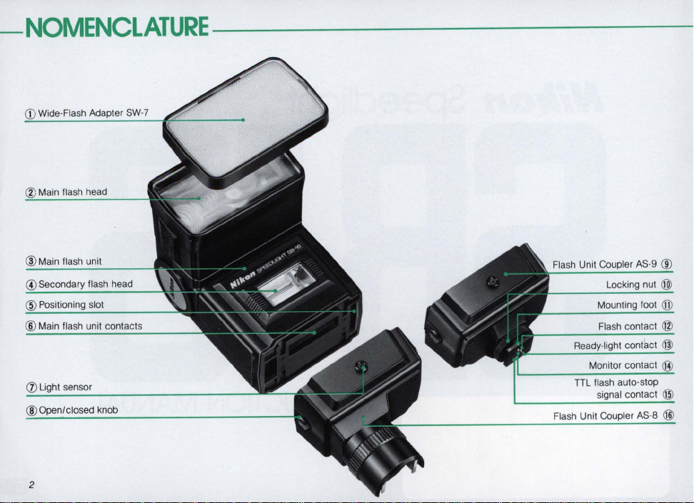
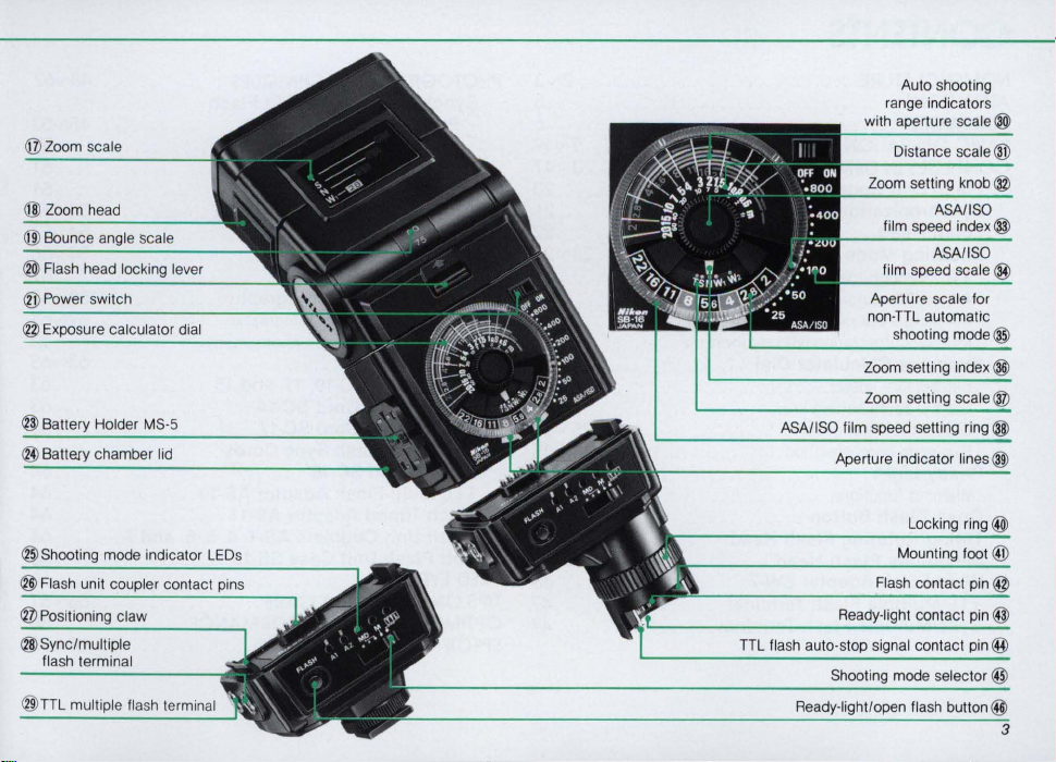
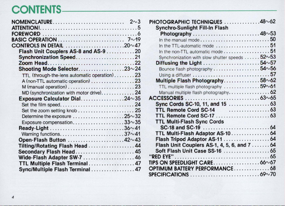
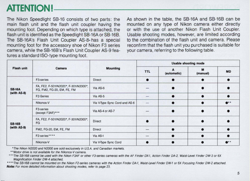
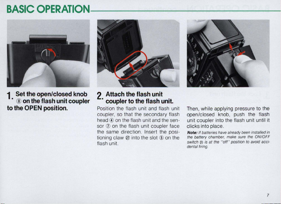
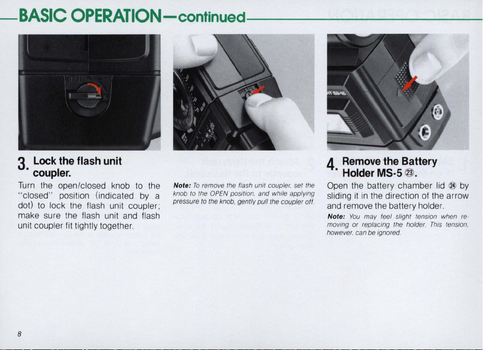
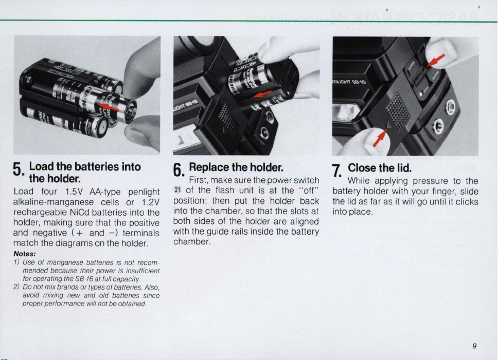
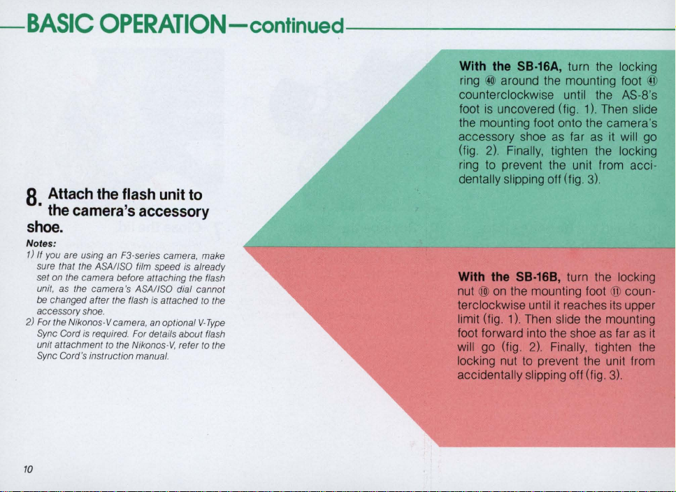
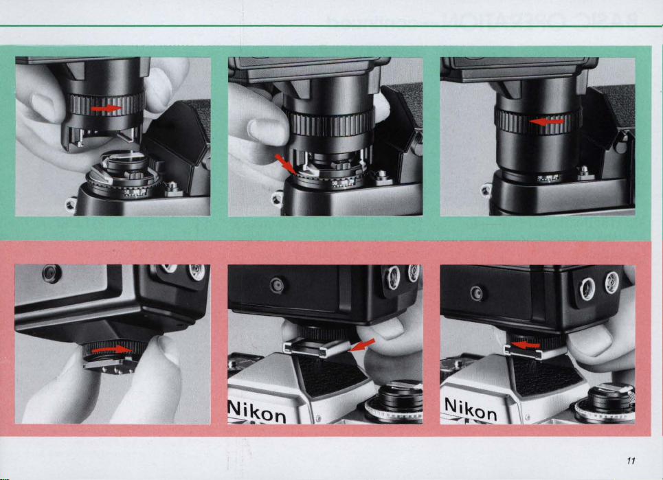
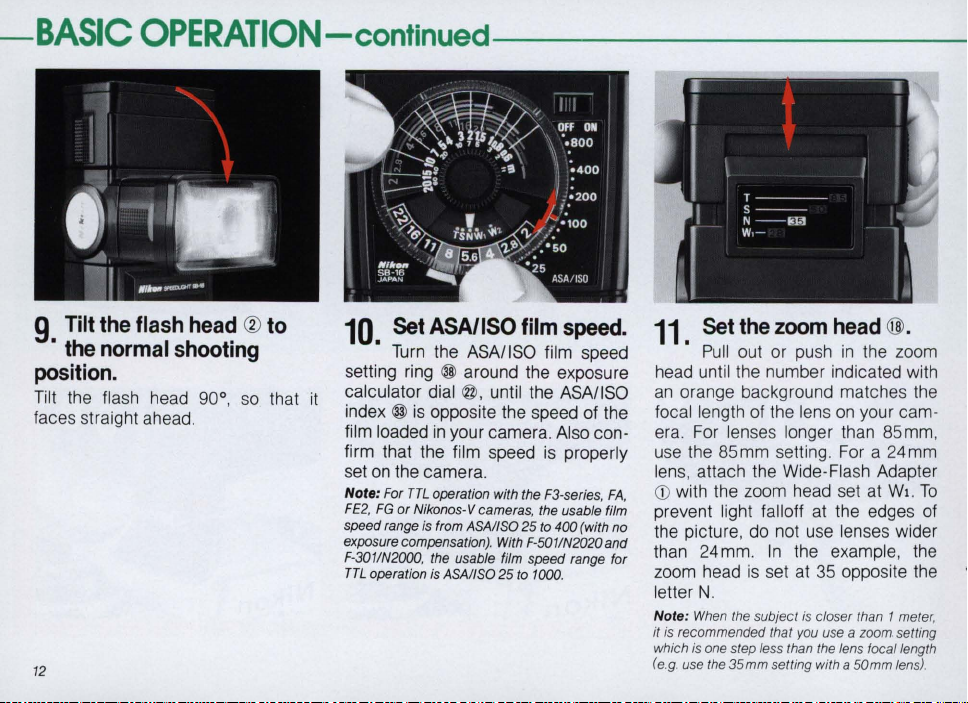
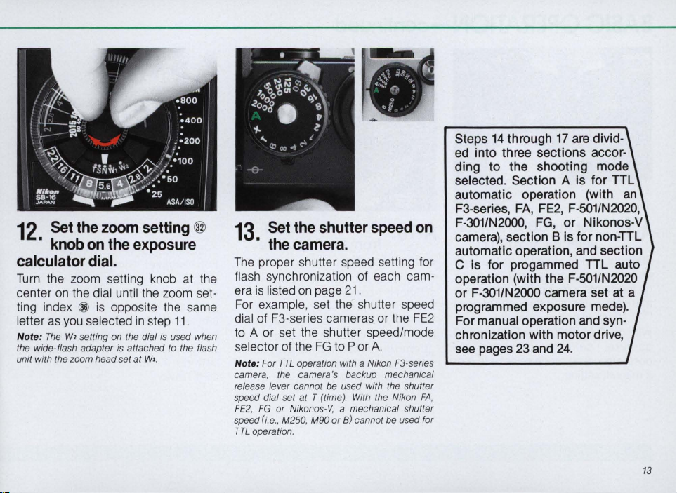
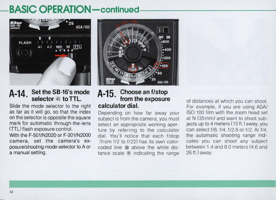
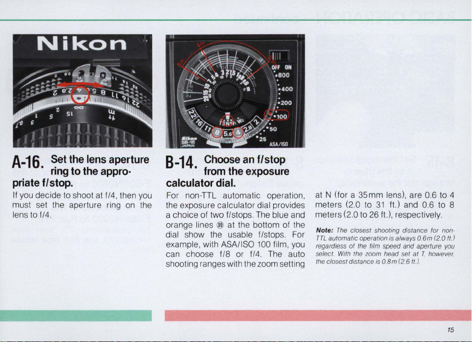
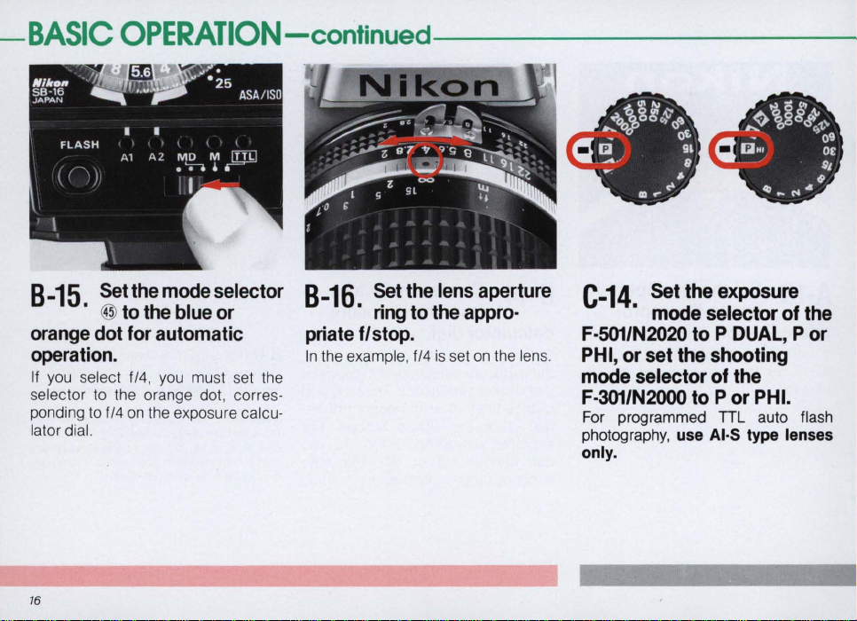
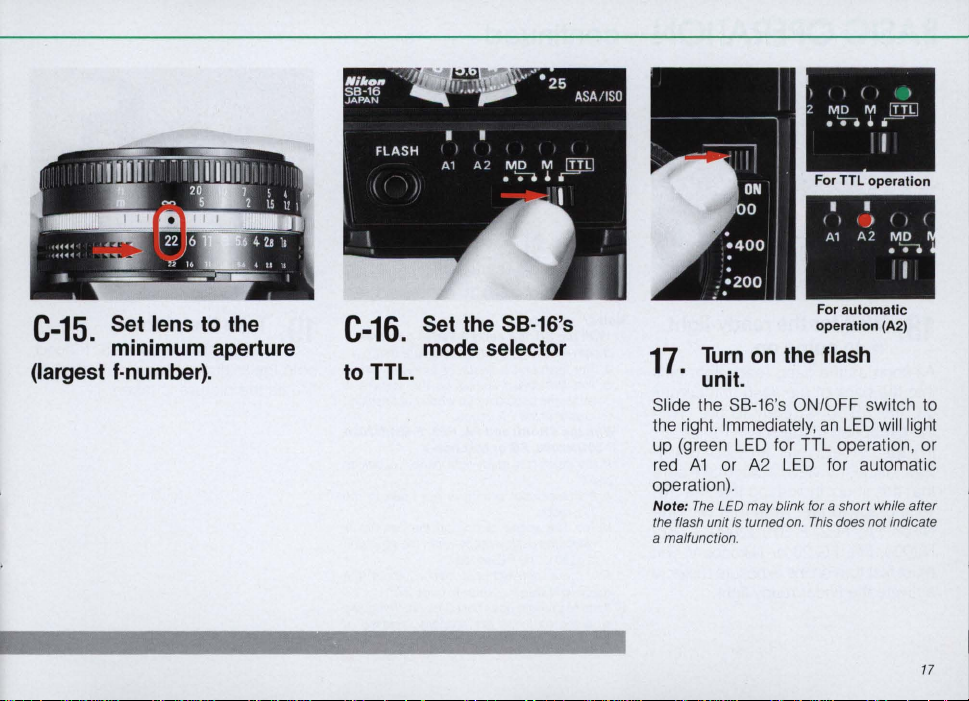
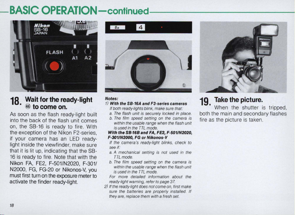
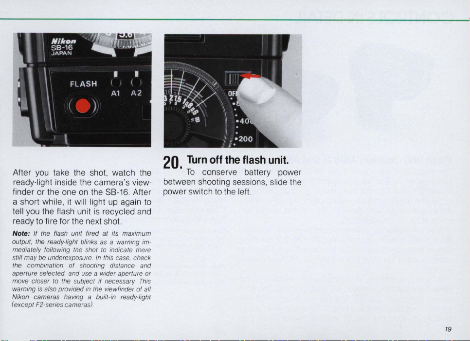
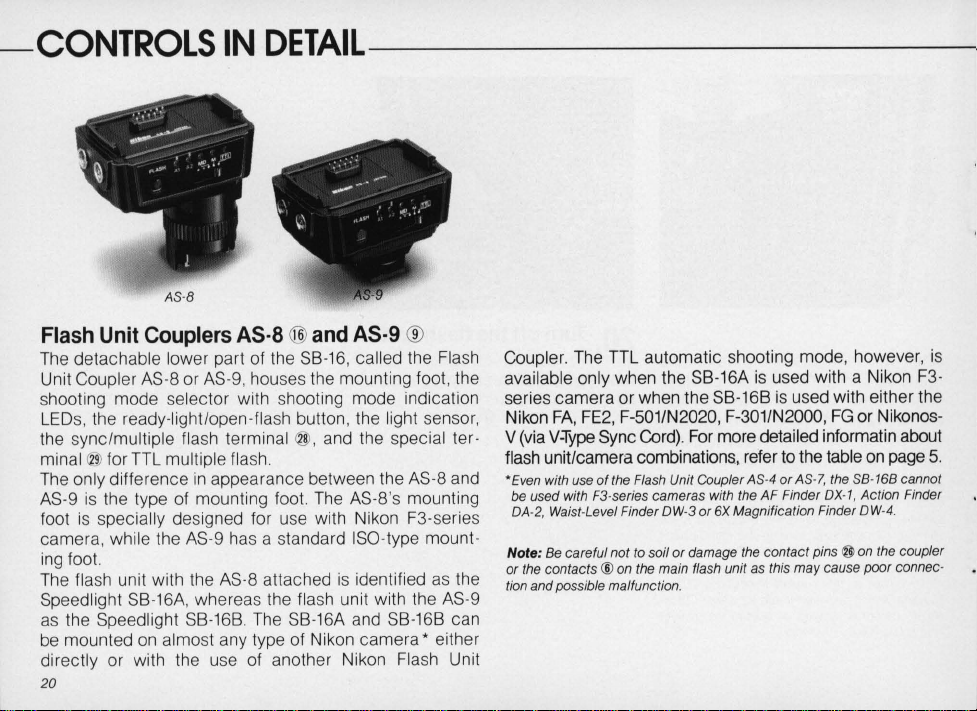
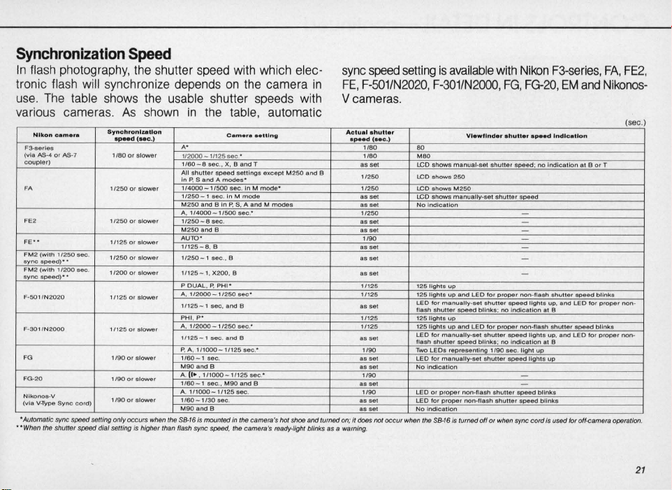
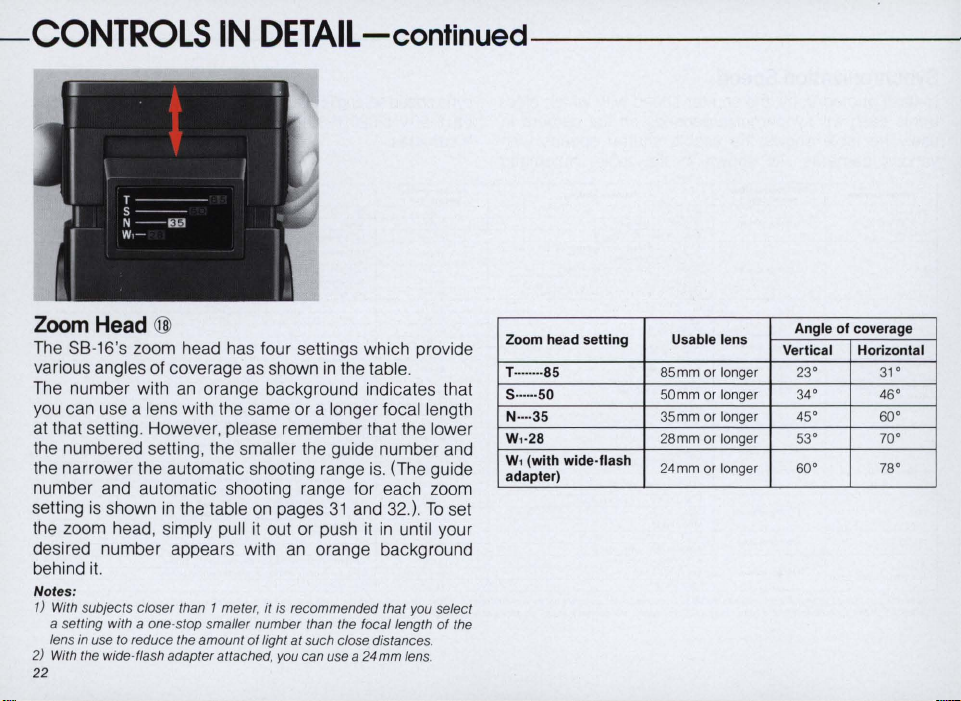


 Loading...