

Page 1
Nikon
Speedlight
INSTRUCTION MANUAL
Page 2
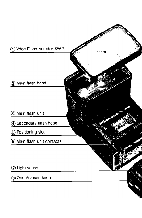
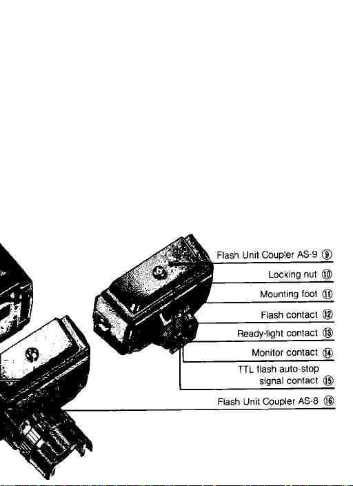
NOMENCLATURE
Page 3
Page 4
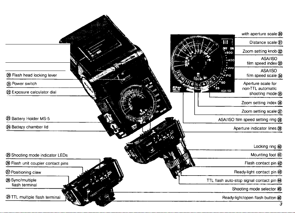
) Zoom scale
(3) Zoom head
®) Bounce angle scale
Auto shooting
range indicators
Page 5

CONTENTS-----------------------------
NOMENCLATURE........................................................... 2~3
ATTENTION!.........................................................................5
FOREWORD
BASIC OPERATION...................................................... 7~19
CONTROLS IN DETAIL................................................20~47
Flash Unit Couplers AS-8 and AS-9
Synchronization Speed...............................................21
Zoom Head....................................................................22
Shooting Mode Selector
Exposure Calculator Dial
Ready-Light...........................................................36''^ 41
Warning functions...............................................37~41
Open-Flash Button.................................................42~43
Tilting/Rotating Fiash Head.........................................44
Secondary Fiash Head.................................................45
Wide-Flash Adapter SW-7............................................46
TTL Multiple Flash Terminal........................................47
Sync/Multiple Flash Terminal
.........................................................................
...........................
.......................................
TTL (through-the-lens automatic operation)
A (non-TTL automatic operation).............................23
M (manual operation)
MD (synchronization with motor drive)
Set the film speed
Set the zoom setting knob........................................25
Determine the exposure
Exposure compensation.....................................33~35
................................................
...................
..................................
......................................................
.....................................
.....................................
23'^24
..........
24^^^35
25~32
20
23
23
24
24
47
6
Page 6

PHOTOGRAPHIC TECHNIQUES
.............................
48'^62
Synchro-Sunlight Fill-In Flash
Photography......................................................48~53
In the manual mode
In the TTL-automatIc mode
In the non-TTL automatic mode
Synchronization with slow shutter speeds
.................................................
.....................................
........... ...................
...........
50
51
51
52~53
Diffusing the Light................................................54~57
Bounce flash photography
Using a diffuser
..........................................................
Multiple Flash Photography
TTL multiple flash photography
Manual multiple flash photography
...................................
................................
...........................
............................
54~56
57
58^62
59~61
62
ACCESSORIES...........................................................63~65
Sync Cords SC-10,11, and 15
....................................
63
TTL Remote Cord SC-14 63
TTL Remote Cord SC-17
............................................
63
TTL Multi-Flash Sync Cords
SC-18 and SC-19
TTL Multi-Flash Adaptor AS-10
Flash Tripod Adaptor AS-11
Flash Unit Couplers AS-1, 4, 5, 6, and 7
....................................................
.................................
......................................
...................
64
64
64
64
Soft Flash Unit Case SS-16........................................65
“RED EYE”........................................................................65
TIPS ON SPEEDLIGHT CARE
...................................
66~67
OPTIMUM BATTERY PERFORMANCE...........................68
SPECIFICATIONS.......................................................69~70
Page 7

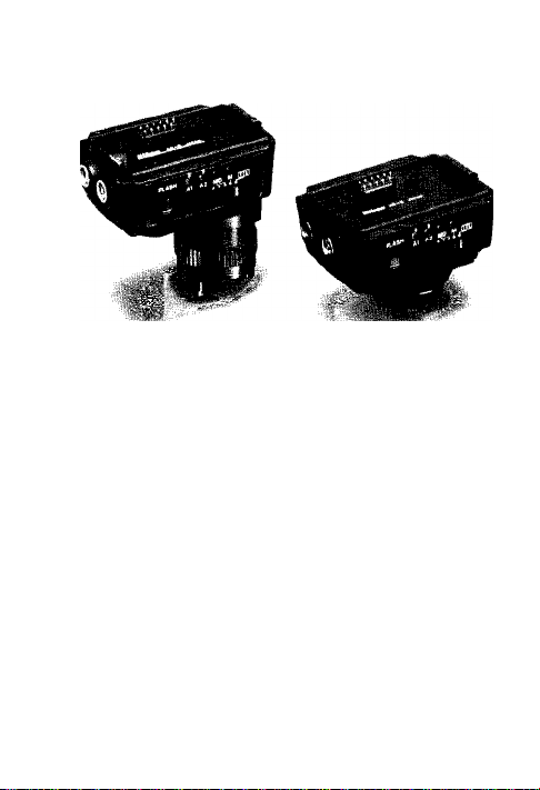
ATTENTION!
The Nikon Speedlight SB-16 consists of two parts: the
main fiash unit and the fiash unit coupier having the
mounting foot. Depending on which type is attached, the
fiash unit is identified as the Speediight SB-16Aor SB-16B.
The SB-16A’s Fiash Unit Coupier AS-8- has a speciai
mounting foot for the accessory shoe of Nikon F3 series
camera, whiie the SB-16B’s Fiash Unit Coupier AS-9 fea
As shown in the tabie, the SB-16A and SB-16B can be
mounted on any type of Nikon camera either directly
or with the use of another Nikon Fiash Unit Coupier.
Usabie shooting modes, however, are iimited according
to the combination of the fiash unit and camera. Piease
reconfirm that the fiash unit you purchased is suitable for
your camera, referring to the foiiowing table.
tures a standard ISO-type mounting foot.
Flash unit
F3-series
SB-16A
(with AS-8)
SB-16B
(with AS-9)
*The Nikon N2020 and N2000 are sold exclusively in US.A. and Canadian markets.
* * Motor drive is not available for the Nikonos-V camera.
***The SB-16B cannot be used with the Nikon F3AF or other F3-series cameras with the AF Finder DX-1, Action Finder DA-2, Waist-Level Finder DW-3 or 6X
Magnification Finder DW-4 attached.
****The SB-16B cannot be mounted on the Nikon F2-series cameras with the Action Finder DA-1, Waist-Level Finder DW-1 or 6X Focusing Finder DW-2 attached.
Note: For more detailed information about shooting modes, refer to page 23.
FA, FE2, F-501/N2020*. F-301/N2000*.
FG. FM2, FG-20, EM, FE, FM
F2-Series Via AS-5
Nikonos-V
F3-series
(except F3AF)***
FA. FE2, F-501/N2020*, F-301/N2000*.
FG
FM2, FG-20, EM, FE, FM Direct
F2-series****
Nikonos-V
Cam era Mounting
Direct
Via AS-6
Via V-Type Sync Cord and AS-6
ViaAS-4orAS-7
Direct
Via AS-1
Via V-Type Sync Cord
TTL
• • •
-
-
-
-
• • • •
-
—
• •
Usa ble shooting mode
A
(automatic)
•
•
• •
•
• • •
• • •
M
(ma nual)
• •
• •
•
•
MD
•
•
Page 8

FOREWORD
The Nikon Speedlight SB-16 is a direct-mounting eiec-
tronic fiash unit, providing automatic through-the-iens
(TTL) controi of the fiash exposure when used with Nikon
cameras having TTL flash capabiiity. Through the use of
an interchangeable mounting foot, the SB-16 can be at
tached to the speciai accessory shoe of ali Nikon F3series cameras, as weli as the standard ISO-type shoe
of the Nikon FA, FE2, F-501/N2020, F-301/N2000 and FG
camera, or the V-type Sync Cord for the Nikonos-V. Because
light is measured through the picture-taking lens, you are
assured of just the right exposure with a variety of lenses and
accessory attachments at any aperture from f/2 to f/22.
Programmed TTL auto flash photography can be performed
by using the SB-16 with the Nikon F-501/N2020 or
F-301/N2000 via the AS-9. In programmed TTL auto flash
photography, the proper aperture is automatically set for
correct exposure according to the film speed in use. It is not
necessary to change the lens setting from the minimum
aperture used for non-flash programmed shooting.
Thanks to the incorporation of a front-mounted light
sensor, the SB-16 is also compatible with all other Nikon
cameras for automatic, but not through-the-iens, flash
output control. In the non-TTL automatic mode, you have
a choice of two apertures. With a silicon-controlled recti
fier and series circuitry, the SB-16 is able to conserve
energy when shooting subjects at close range; thus re
cycling times are shorter and the number of flashes per
battery set is greater.
Page 9

For truly creative bounce flash photography, the Nikon
Speedlight SB-16 has two separate flash heads—a
combination of tilting and rotating main flash head with
zooming capability and a smaller secondary flash head
which faces straight ahead to fill in the shadows in the
eye sockets and provide a small catchlight for the eyes.
Moreover, a special MD setting allows the SB-16 to
synchronize with a motor-driven camera firing at 4
frames per second for shooting 8 pictures in series.
Even though the SB-16 is extremely easy to use, you
should familiarize yourself with its "Basic Operation” as
presented in the first section. For more detailed infor
mation, please refer to "Controls in Detail" and "Photo
graphic Techniques." A few minutes wisely invested now
will pay off later in years of rewarding photographic
experiences.
To insure proper service, make sure the Nikon Warranty
Card is enclosed in the speedlight box.
Page 10
BASIC OPERATION
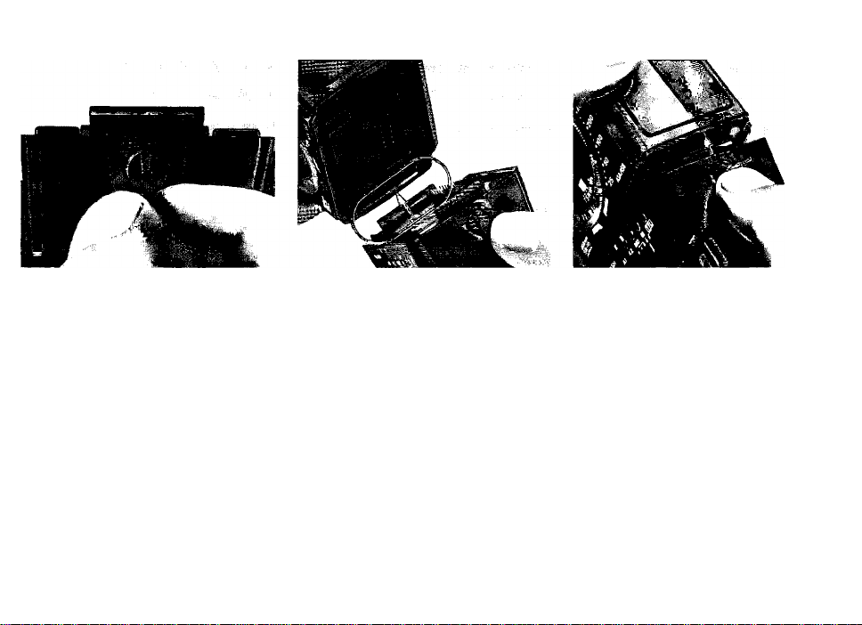
“I Set the open/closed knob
' ® on the flash unit coupler
to the OPEN position.
2 Attach the flash unit
' coupler to the flash unit.
Position the flash unit and flash unit
coupler, so that the secondary flash
head ® on the flash unit and the sen
sor ® on the flash unit coupler face
the same direction. Insert the posi
tioning claw @ into the slot (D on the
flash unit.
Then, while applying pressure to the
open/closed knob, push the flash
unit coupler into the flash unit until it
clicks into place.
Note: It batteries have already been installed in
the battery chamber, make sure the ON/OFF
switch ® is at the "otf" position to avoid acci
dental firing.
Page 11
BASIC OPERATION —continued-
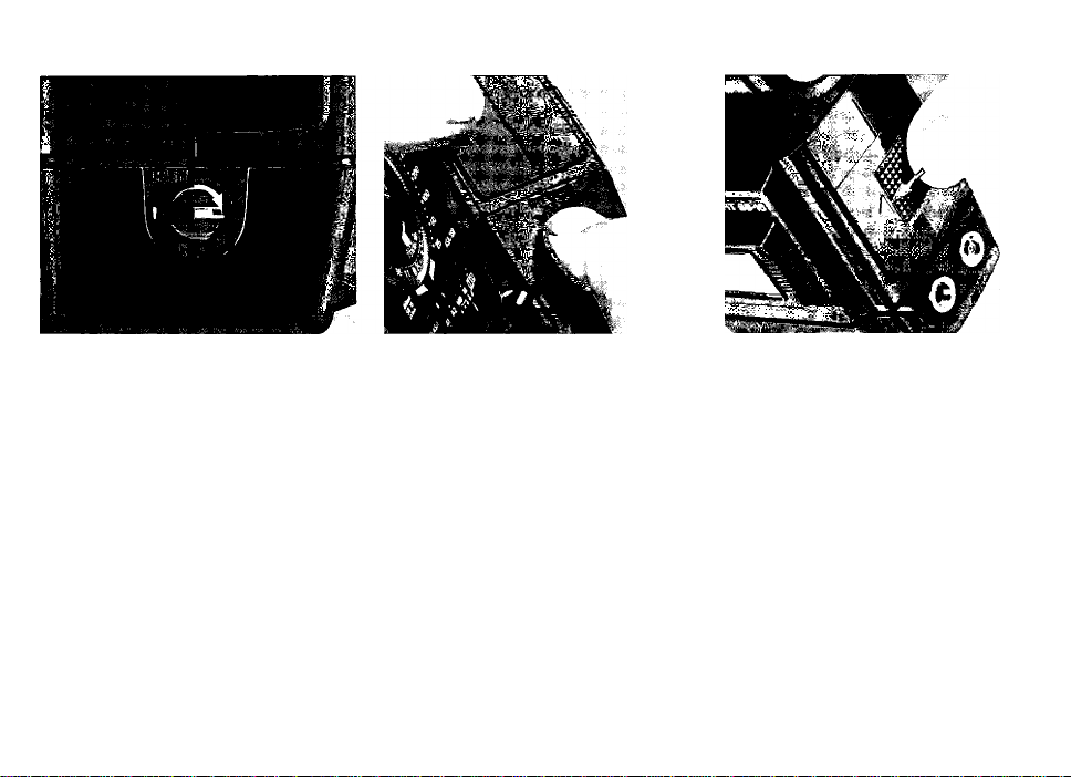
2 Lock the flash unit
' coupler.
Turn the open/closed knob to the
“closed" position (indicated by a
dot) to lock tne flash unit coupler;
make sure the flash unit and flash
unit coupler fit tightly together.
Note: To remove the flash unit coupler, set the
knob to the OPEN position, and while applying
pressure to the knob, gently pull the coupler off.
A Remove the Battery
Holder MS-5 ®.
Open the battery chamber lid (|$ by
sliding it in the direction of the arrow
and remove the battery holder.
Note: You may feel slight tension when re
moving or replacing the holder. This tension,
however, can be ignored.
Page 12
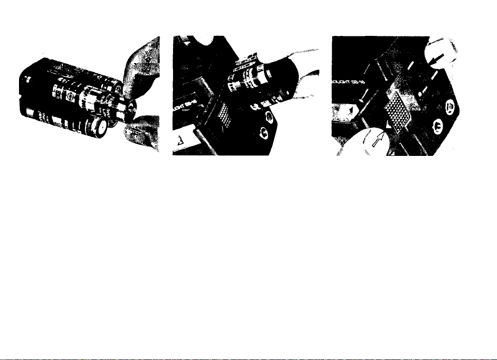
5 Load the batteries into
' the holder.
Load four 1.5V AA-type penlight
alkaline-manganese cells or 1.2V
rechargeable NiCd batteries into the
holder, making sure that the positive
and negative ( + and -) terminals
match the diagrams on the holder.
Notes:
1) Use of manganese batteries is not recom
mended because their power is insufficient
for operating the SB-16 at full capacity.
2) Do not mix brands or types of batteries. Also,
avoid mixing new and old batteries since
proper performance will not be obtained.
0 Replace the holder.
' First, make sure the power switch
@ of the flash unit is at the “off”
position; then put the holder back
into the chamber, so that the slots at
both sides of the holder are aligned
with the guide rails inside the battery
chamber.
y Close the lid.
' While applying pressure to the
battery holder with your finger, slide
the lid as far as it will go until it clicks
into place.
Page 13

BASIC OPERATION —continued-
g Attach the flash unit to
' the camera’s accessory
shoe.
Notes:
1) If you are using an F3-series camera, make
sure that the ASA/ISO film speed is already
set on the camera before attaching the fiash
unit, as the camera's ASA/ISO dial cannot
be changed after the flash is attached to the
accessory shoe.
2) For the NIkonos-Vcamera, an optional V-Type
Sync Cord is required. For details about flash
unit attachment to the Nikonos-V, refer to the
Sync Cord's instruction manual.
10
Page 14

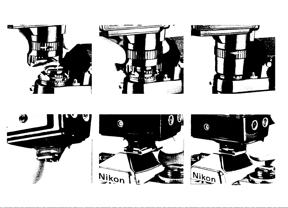
With the SB-16A, turn the locking
ring @ around the mounting foot @
counterclockwise until the AS-8's
foot is uncovered (fig. 1). Then slide
the mounting foot onto the camera's
accessory shoe as far as it will go
(fig. 2). Finally, tighten the locking
ring to prevent the unit from acci
dentally slipping off (fig. 3).
With the SB-16B, turn the locking
nut ® on the mounting foot (0 coun
terclockwise until it reaches its upper
limit (fig. 1). Then slide the mounting
foot forward into the shoe as far as it
will go (fig. 2). Finally, tighten the
locking nut to prevent the unit from
accidentally slipping off (fig. 3).
Page 15
Page 16
BASIC OPERATION —continued
Q Tilt the flash head ® to
' the normal shooting
position.
Tilt the flash head 90°, so that it
faces straight ahead.
12
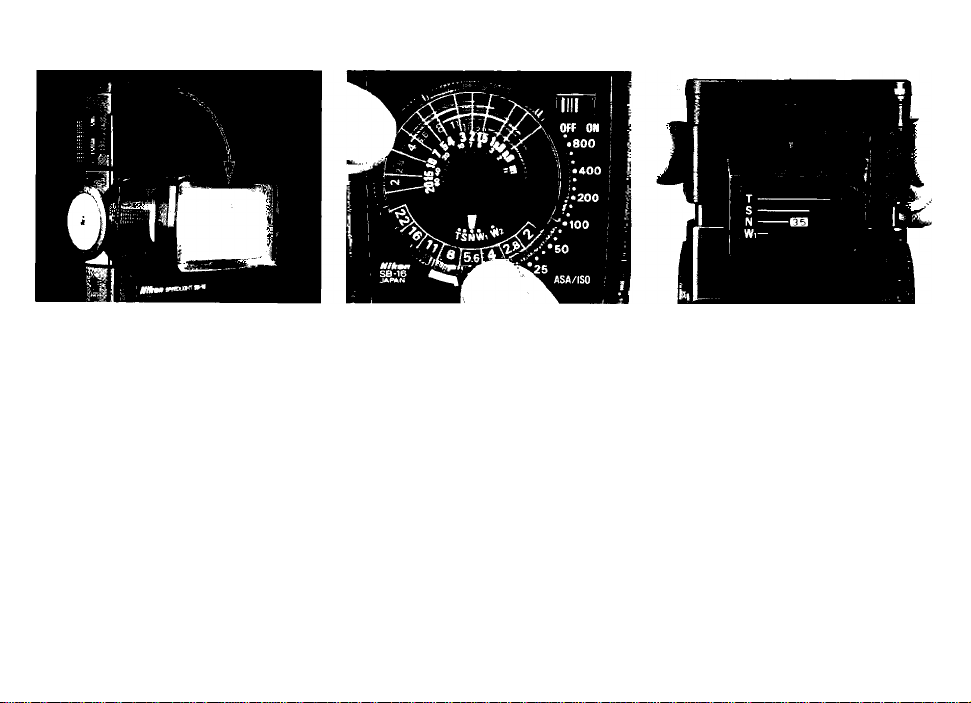
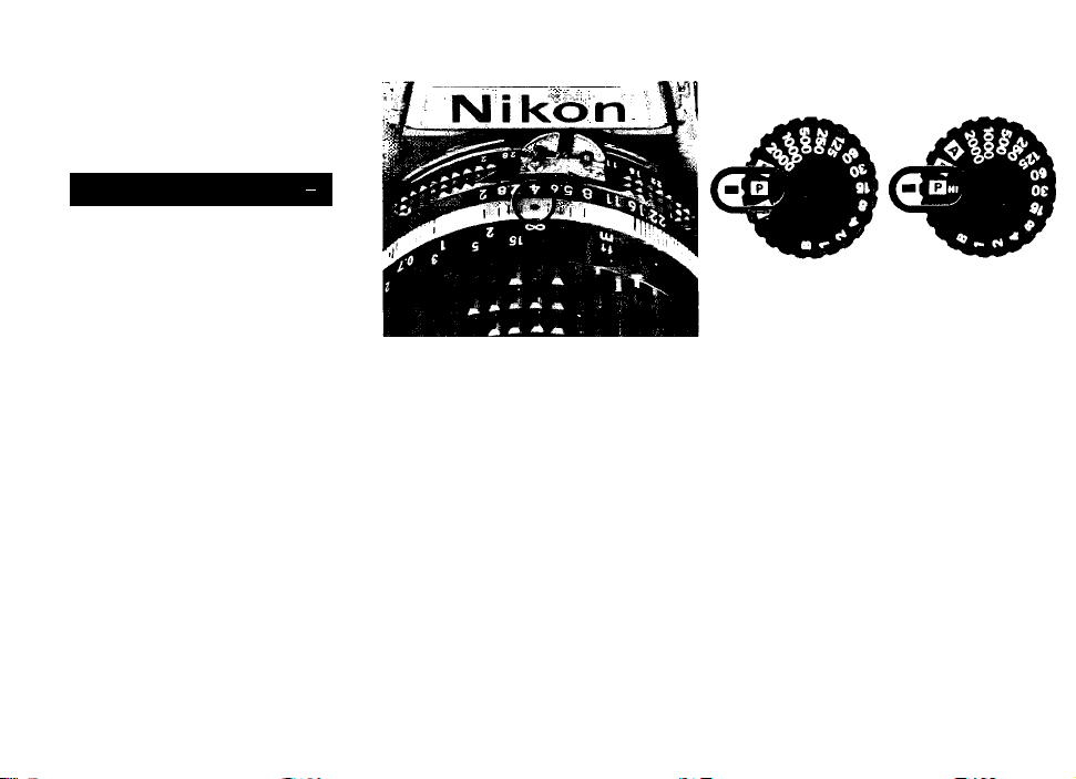
'IQ Set ASA/ISO film speed.
' Turn the ASA/ISO film speed
setting ring ® around the exposure
calculator dial until the ASA/ISO
index ® is opposite the speed of the
film loaded in your camera. Also con
firm that the film speed is properly
set on the camera.
Note: For TTL operation with the F3-series, FA,
FE2, FG or Nikonos-V cameras, the usable film
speed range is from ASA/ISO 25 to 400 (with no
exposure compensation). With F-501/N2020 and
F-301/N2000, the usabte fiim speed range for
TTL operation is ASA/ISO 25 to 1000.
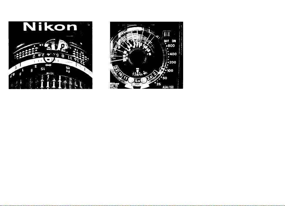
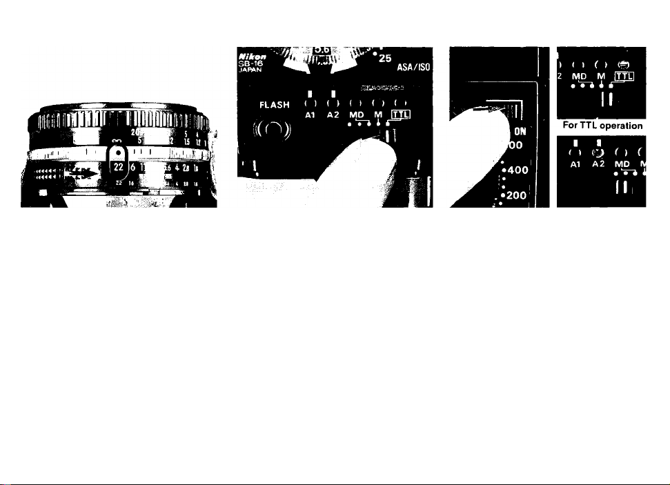
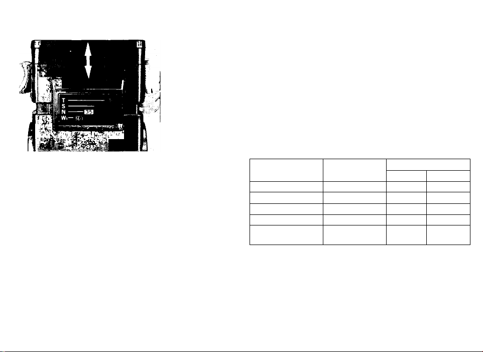
-|“( Set the zoom head d3).
' Pull out or push in the zoom
head until the number indicated with
an orange background matches the
focal length of the lens on your cam
era. For lenses longer than 85mm,
use the 85mm setting. For a 24mm
lens, attach the Wide-Flash Adapter
® with the zoom head set at Wi. To
prevent light falloff at the edges of
the picture, do not use lenses wider
than 24mm. In the example, the
zoom head is set at 35 opposite the
letter N.
Note: When the subject is closer than 1 meter,
it is recommended that you use a zoom, setting
which is one slep less than the lens local length
(e.g. use the 35mm setting with a 50mm lens).
Page 17
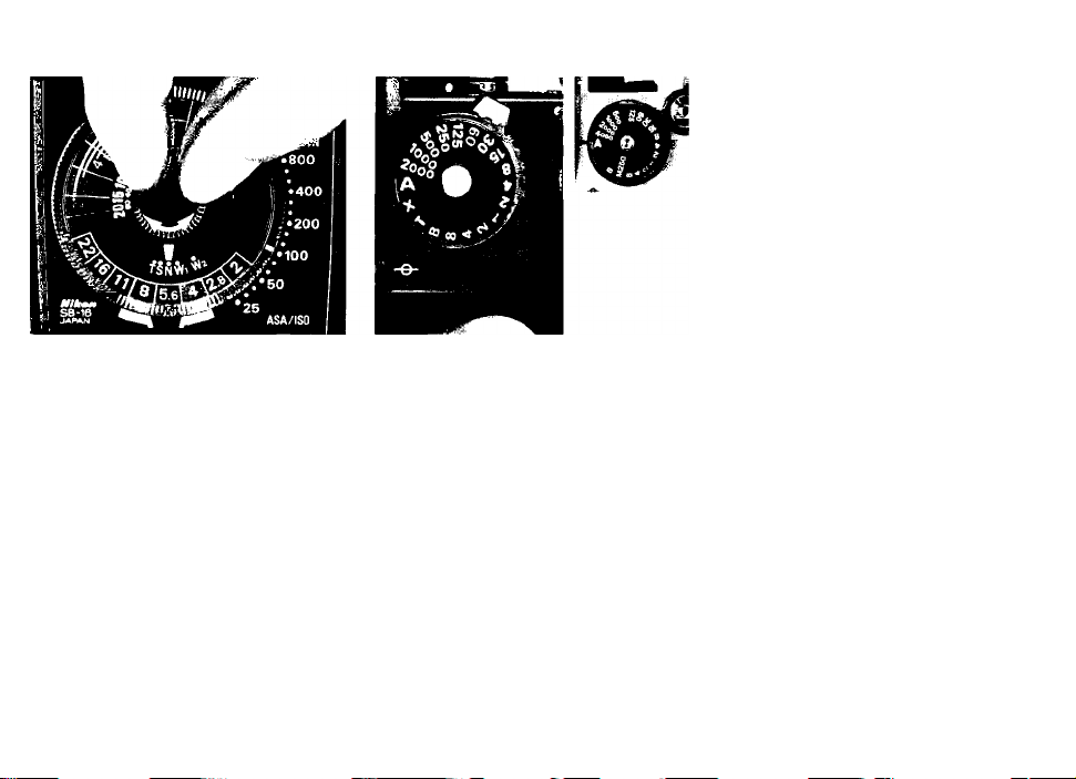
12. Set the zoom setting ®
' knob on the exposure
calculator dial.
Turn the zoom setting knob at the
center on the dial until the zoom set
ting index @) is opposite the same
letter as you selected in step 11.
Note: The Wi setting on the dial is used when
the wide-flash adapter is attached to the flash
unit with the zoom head set at Wi.
13. Set the shutter speed on
' the camera.
The proper shutter speed setting for
flash synchronization of each cam
era is listed on page 21.
For example, set the shutter speed
dial of F3-series cameras or the FE2
to A or set the shutter speed/mode
selector of the FG to P or A.
Note: For TTL operation with a Nikon F3-series
camera, the camera's backup mechanical
release lever cannot be used with the shutter
speed dial set at T (time). With the Nikon FA.
FE2. FG or Nikonos-V, a mechanical shutter
speed (i.e., M250. M90 or B) cannot be used for
TTL operation.
Steps 14 through 17 are divid-'
ed into three sections accor-'
ding to the shooting mode ’
seiected. Section A is for TTL\
automatic operation (with anf
F3-series, FA, FE2, F-501/N2020,
F-301/N2000, FG, or Nikonos-V)
camera), section B is for non-TTL
automatic operation, and section
C is for progammed TTL auto
operation (with the F-501/N2020
or F-301/N2000 camera set at a
programmed exposure mede).
For manuai operation and syn
chronization with motor drive,
see pages 23 and 24.
13
Page 18
BASIC OPERATION —continued
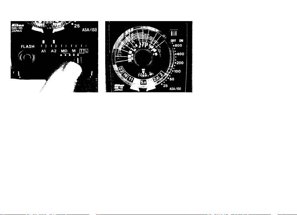
/\_14 Set the SB-16’s mode
■ selector® to TTL
Slide the mode selector to the right
as far as it will go, so that the index
on the selector is opposite the square
mark for automatic through-the-iens
(TTL) flash exposure control.
With the F-501/N2020 or F-301/N2000
camera, set the camera's exposure/shooting mode selector to A or
a manual setting.
14
A-15. Choose an f/stop
■ from the exposure
calculator dial.
Depending on how far away your
subject is from the camera, you must
select an appropriate working aper
ture by referring to the calculator
dial. You'll notice that each f/stop
(from f/2 to f/22) has its own color-
coded line ® above the white dis
tance scale ® indicating the range
of distances at which you can shoot.
For example, if you are using ASA/
ISO
too
film with the zoom head set
at N (35mm) and want to shoot sub
jects up to 4 meters (13 ft.) away, you
can select f/8, f/4, f/2.8 or f/2. At f/4,
the automatic shooting range indi
cates you can shoot any subject
between 1.4 and 8.0 meters (4.6 and
26 ft.) away.
Page 19
A-16. Set the lens aperture
' ring to the appro
priate f/stop.
If you decide to shoot at f/4, then you
must set the aperture ring on the
lens to f/4.
B-14. Choose an f/stop
' from the exposure
calculator dial.
For non-TTL automatic operation,
the exposure calculator dial provides
a choice of two f/stops. The blue and
orange lines (§> at the bottom of the
dial show the usable f/stops. For
example, with ASA/ISO 100 film, you
can choose f/8 or t/4. The auto
shooting ranges with the zoom setting
at N (for a 35mm lens), are 0.6 to 4
meters (2.0 to 31 ft.) and 0.6 to 8
meters(2.0 to 26 ft.), respectively.
Note: The closest shooting distance lor non-
TTL automatic operation is always 0.6m (2.0 ft.)
regardless ol the film speed ahd aperture you
select. With the zoom head set at T however,
the closest distance is 0.8m (2.6 ft.).
15
Page 20
—BASIC OPERATION—continued
FLASH I > I » I I ( > I '
A1 A2 MD M ITTLJ
B -15 mode selector
■ ® to the blue or
orange dot for automatic
operation.
If you select f/4, you must set the
selector to the orange dot, corres
ponding to f/4 on the exposure calcu
lator dial.
76
B-16. Set the iens aperture
' ring to the appro
priate f/stop.
In the example, t/4 is set on the lens.
C-14. Set the exposure
' mode selector of the
F-501/N2020 to P DUAL, P or
PHI, or set the shooting
mode selector of the
F-301/N2000 to P or PHI.
For programmed TTL auto flash
photography, use Al-S type lenses
only.
Page 21
C-15. Set lens to the
' minimum aperture
(largest f-number).
Q_'|0 Set the SB-16’s
' mode selector
to TTL.
For automatic
operation (A2)
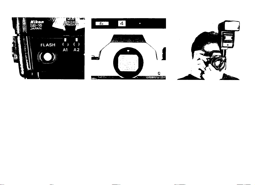
17. Turn on the flash
' unit.
Slide the SB-16’s ON/OFF switch to
the right. Immediately, an LED will light
up (green LED for TTL operation, or
red At or A2 LED for automatic
operation).
Note: The LED may blink for a short while after
the flash unit is turned on. This does not indicate
a malfunction.
17
Page 22
BASIC OPERATION-continued
18. Wait for the ready-light
■ (@) to come on.
As soon as the flash ready-light built
into the back of the flash unit comes
on, the SB-16 is ready to fire. With
the exception of the Nikon F2-series,
if your camera has an LED readylight inside the viewfinder, make sure
that it is lit up, indicating that the SB-
16 is ready to fire. Note that with the
Nikon FA, FE2, F-501/N2020, F-301/
N2000, FG, FG-20 or Nikonos-V, you
must first turn on the exposure meter to
activate the finder ready-light.
18
Notes:
1) With the SB-16A and F3-series cameras
If both ready-lights blink, make sure that:
a. The flash unit is securely locked in place.
b. The film speed setting on the camera is
within the usable range when the flash unit
is used in theTTL mode.
With the SB-16B and FA, FE2, F S01/N2020,
F-301/N2000, FG or Nikonos-V
If the camera's ready-light blinks, check to
see If:
a. A mechanical setting is not used in the
TTL mode.
b. The film speed setting on the camera is
within the usable range when the flash unit
is used in theTTL mode.
For more detailed information about the
ready-light warning, refer to page 37.
2) If the ready-light does not come on, first make
sure the batteries are properly installed. If
they are, replace them with a fresh set.
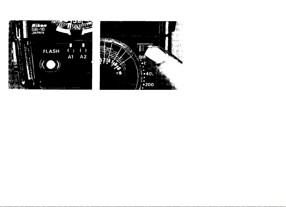
19. Take the picture.
' When the shutter is tripped,
both the main and secondary flashes
fire as the picture is taken.
Page 23
After you take the shot, watch the
ready-light inside the camera’s view
finder or the one on the SB-16. After
a short while, it will light up again to
tell you the flash unit is recycled and
ready to fire for the next shot.
Note; If the flash unit fired at its maximum
output, the ready-light blinks as a warning im
mediately following the shot to indicate there
still may be underexposure. In this case, check
the combination of shooting distance and
aperture selected, and use a wider aperture or
move closer to the subject if necessary. This
warning is also provided in the viewfinder of all
Nikon cameras having a built-in ready-light
(except F2-series cameras).
20. Turn off the flash unit.
' To conserve battery power
between shooting sessions, slide the
power switch to the left.
19
Page 24
CONTROLS IN DETAIL
AS-8
Flash Unit Couplers AS-8 ® and AS-9 (D
The detachable lower part of the SB-16, called the Flash
Unit Coupler AS-8 or AS-9, houses the mounting foot, the
shooting mode selector with shooting mode indication
LEDs, the ready-iight/open-flash button, the iight sensor,
the sync/muitipie fiash terminal ®, and the special ter
minal ® forTTL multiple flash.
The only difference in appearance between the AS-8 and
AS-9 is the type of mounting foot. The AS-8’s mounting
foot is specially designed for use with Nikon F3-series
camera, while the AS-9 has a standard ISO-type mount
ing foot.
The flash unit with the AS-8 attached is identified as the
Speedlight SB-16A, whereas the flash unit with the AS-9
as the Speedlight SB-16B. The SB-16A and SB-16B can
be mounted on almost any type of Nikon camera* either
directly or with the use of another Nikon Flash Unit
20
Page 25

Coupler. The TTL automatic shooting mode, however, is
available only when the SB-16A is used with a Nikon F3series camera or when the SB-16B is used with either the
Nikon FA, FE2, F-501/N2020, F-301/N2000, FG or Nikonos-
V (via V-Type Sync Cord). For more detailed informatin about
flash unit/camera combinations, refer to the table on page 5.
*Even with use of the Flash Unit Coupler AS-4 orAS-7, the SB-/68 cannot
be used with F3-series cameras with the AF Finder DX-1, Action Finder
DA-2, Waist-Level Finder DW-3 or 6X Magnification Finder DW-4.
Note: Be careful not to soil or damage the contact pins ® on the coupler
or the contacts d) on the m ain flash unit as this may cause poor connec
tion and possible malfunction.
Page 26

Synchronization Speed
In flash photography, the shutter speed with which elec
tronic flash will synchronize depends on the camera in
use. The table shows the usable shutter speeds with
various cameras. As shown in the table, automatic
Nikon cantor«
F3-eeries
(via AS-4 or AS-7
coupler)
FA
FE2 1 /250 or slower
FE** 1/125 or slower
FM2(with 1/250 sec.
sync speed)**
FM2 (with 1/200 sec.
sync speed)**
F-501/N2020 1/125 or slower
F-301/N2000 1 /125 or slower
FG
FQ-20
NIkonos-V
(via V-iype Sync cord)
‘Automatic sync speed setting only occurs when the SB-16 Is mounted in the camera's hot shoe and turned
“When the shutter speed dial setting Is higher than flash sync speed, the camera's ready-light blinks as a
Synchronization
speed (sec.)
1/60 or slower
1/250 or slower
1/250 or slower
1 /200 or slower
1/90 or slower
1/90 or slower
1 /90 or slower
A*
1/2000-1/125 sec.*
1 /60 — 8 sec., X, В and T
All shutter speed settings except M250 and В
in P. S and A modes*
1 /4000 -1 /500 sec. In M mode* 1/250 LCD shows M250
1/250 — 1 sec. In M mode
M250 and В In P. S. A and M modes as set No Indication
A, 1 /4000 - 1 /500 sec *
1/250-8 sec.
M250 and В
AUTO*
1/125-8. В
1/250-1 sec., В
1/125-1. X200, В as set
P DUAL, P, PHI*
A, 1/2000-1/250 sec*
1/125 — 1 sec. and В as set
PHI, P*
A, 1/2000-1/250 sec *
1/125-1 sec. and В
P, A, 1 /1000 -1 /125 sec.*
1/60-1 sec.
M90 and В
A. ((► . 1 /1000 -1 /125 sec *
1/60- 1 sec., M90 and В
A. 1/1000-1/125 sec. 1/90
1/60-1 /30 sec
M90 and 8
Camera setting
sync speed setting is available with Nikon F3-series, FA, FE2,
FE, F-501/N2020, F-301/N2000, FG, FG-20, EM and Nikonos-
V cameras.
Actual shutter
apaed (aae.)
1/80 80
1/80
as set LCD shows manual-set shutter speed; no indication at B or T
1/250 LCD shows 250
as set LCD shows manually-set shutter speed
1/250
as set
as set
1/90
as set
as set
1/125
1/125 125 lights up and LED tor proper non-flash shutter speed blinks
1/125 125 lights up
1/125 125 lights up and LED for proper non-flash shutter speed blinks
as sel
1/90
as set
as set No indication
1/90
as set
as set
as set No Indication
on; It does not occur when the SB-16 is turned off or when sync cord is used for off-camera operation,
warning.
M80
125 tights up
LED for manuaily-set shutter speed lights up. and LED tor proper non
flash shutter speed blinks; no indication at B
LED for manually-set shutter speed lights up. and LED for proper non
flash shutter speed blinks: no indication at B
Two LEDs representing 1/90 sec. light up
LED for manually-set shutter speed lights up
LED or proper non-flash shutter speed blinks
LED for proper norvflash shutter speed blinks
Vlawdnder shutter speed Indication
—
—
—
—
—
-
-
—
—
(sec.)
21
Page 27
CONTROLS IN DETAIL —continued
Zoom Head ®
The SB-16's zoom head has four settings which provide
various angles of coverage as shown in fhe fable.
The number with an orange background indicates that
you can use a lens with the same or a longer focal length
at that setting. However, please remember that the lower
the numbered setting, the smaller the guide number and
the narrower the automatic shooting range is. (The guide
number and automatic shooting range for each zoom
setfing is shown in the table on pages 31 and 32.). To set
the zoom head, simply pull it out or push it in until your
desired number appears with an orange background
behind it.
Notes:
1) With subjects ctoser than 1 meter, it is recommended that you setect
a setting with a one-stop smatler number than the focal length of the
tens in use to reduce the amount ol light at such close distances.
2) With the wide-flash adapter attached, you can use a 24mm tens.
22
Zoom head setting Usable lens
T.........85 85 mm or longer
S--50 50 mm or longer 34° 46°
N--35
Wi-28 28mm or longer
Wi (with wide-flash
adapter)
35 mm or longer
24 mm or longer
Angle of coverage
Verfical
23° 31°
45°
53°
60° 78°
Horizontal
60°
70°
Page 28
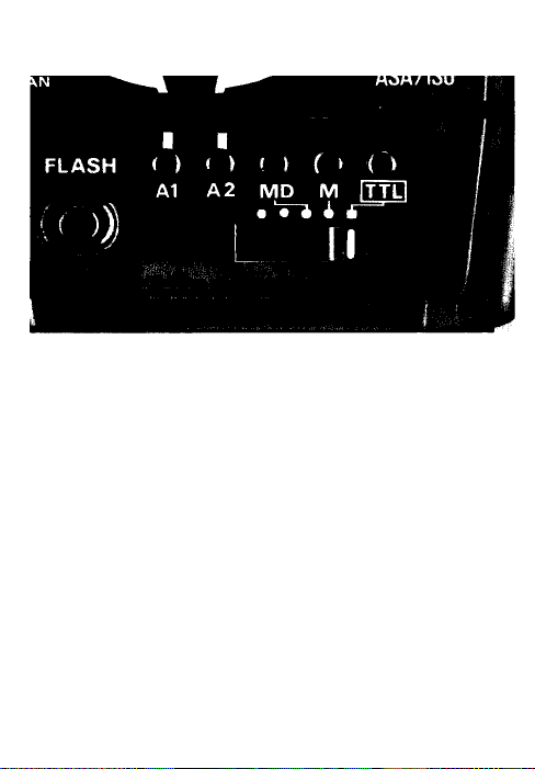
Shooting Mode Selector ®
The shooting mode selector on the back of the SB-16 has
five click-stop settings. Directly above the selector (read
ing from left to right), there are the blue and orange dots
for non-TTL automatic operation, two white dots in the
middle Indicating MD (Motor Drive) and M (Manual)
operation respectively, and a white square at the far righf
which is for TTL operation.
As soon as the SB-16 is turned on, one of the appropriate
LEDs (green for TTL and red for all the rest) above the
selector lights up to indicate the setting selected.
Usable shooting modes depending on the combination of
the type of fhe flash unit and camera are as listed on
page 5.
TTL (through-the-lens automatic operation)
This mode provides automatic through-the-lens (TTL)
Page 29

control of the flash exposure at any aperture from f/2 to
f/22 to match the camera-to-subject distance: the farther
away the subject, the more light emitted by the flash
unit; the closer the subject, the less light given off.
Because the exposure is measured through the lens, no
exposure compensation is required in off-camera and/or
bounce-flash operation or even with a teleconverter or
filter attached to the lens.
This setting is also used for programmed TTL auto opera
tion with F-501/N2020 and F-301/N2000.
A (non-TTL automatic operation)
In the non-TTL automatic (A) mode, the light output of the
flash varies automatically to match the flash-to-subject
distance, but instead of the light being measured through
the lens, it is read by the light sensor on the front of the
SB-16. At any film speed setting, you have a choice of
two working apertures indicated by the blue A1 and
orange A2 aperture indicator lines on the bottom of the
exposure calculator dial.
M (manual operation)
At the manual'('M) setting, the SB-16 fires at its maximum
light output regardless of the flash-to-subject distance.
When it is difficult to obtain correct exposure on auto, i.e.,
when the brightness of the background affects exposure
strongly, use the SB-16 on manual. In the manual mode,
exposure should be determined with the exposure cal
culator dial or with the guide number equation found on
page 30.
23
Page 30
-CONTROLS IN DETAIL —continued
MD (synchronization with motor drive)
At the motor drive (MD) setting, the SB-16 is able to
recycle fast enough to synchronize with a motor-driven
camera firing continuously up to four frames per second.
It is possible to take up to eight flash pictures in rapid
succession in this way. At the MD setting, only the main
flash head fires and the light output is approx, onesixteenth that of the flash unit's maximum power. Like
the M setting, this setting is also for manual operation;
therefore, the exposure should be calculated manually
using the exposure calculator dial or guide number
equation shown on page 30.
Note: As sufficient power is required for the flash unit to synchronize
with a motor drive, use the newest and freshest batteries whenever
possible. For the same reason, avoid tripping the shutter imm ediately
after the ready-light comes on. but wait for at least 30 seconds before
beginning the motor drive sequence.
1000
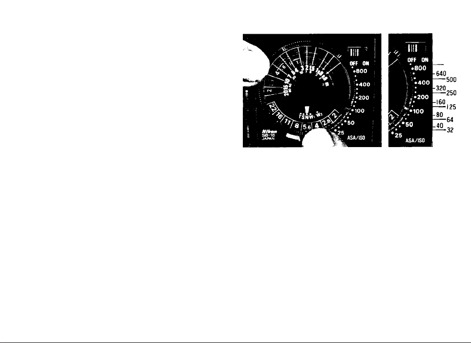
Exposure Calculator Dial ®
The exposure calculator dial on the back of the SB-16
helps you select the aperture you must set on the lens
depending on the camera-to-subject/flash-to-subject
distance. To use the dial, follow these steps:
1)Set the film speed
To set the ASA/ISO film speed, turn the ASA/ISO film
speed setting ring until the number corresponding to the
speed of your film is opposite the ASA/ISO film speed
index. Dots between the numbers on the film speed scale
represent intermediate settings.
24
Page 31

2) Set the zoom setting knob
Turn the zoom setting knob at the center on the dial until
the zoom setting index is opposite the same letter as you
selected in setting the zoom head. For example, if you
set the zoom head at T for a 85mm lens, the zoom set
ting knob must also be set at T.
Note: The setting on the dial is used when the wide-flash adapter Is
attached to the flash unit with the zoom head set at kVi.
Page 32

3) Determine the exposure
Depending on which shooting mode you've selected,
read off the usable f/stop(s) from the dial. In either the
TTL or non-TTL automatic mode, more than one f/stop is
usable. When choosing an aperture, make sure that your
subject is within the auto shooting range indicated by the
color-coded lines. The larger the aperture (the smaller
the f-number) you select, the greater the maximum
shooting distance, whereas the smaller the aperture (the
larger the f-number), the less the maximum shooting
distance. If the subject distance remains the same, the
larger the aperture you select, the less depth of field in
the final photograph; however, the recycling time is
shorter. On the other hand, the smaller the aperture, the
greater the depth of field, but the recycling time is longer.
Therefore, in choosing an f/stop, all these factors should
be taken into consideration.
25
Page 33

-CONTROLS IN DETAIL —continued
For through-the-lens (TTL) operation
On the dial there are eight f/stops ranging from f/2 to
f/22. Each f/stop determines the usable distance range
in which you can obtain the correct automatic exposure.
These ranges are indicated by a series of color-coded
lines above the distance scale.
For programmed TTL operation, it is not necessary to select
the lens aperture. Once the lens is set to its minimum aper
ture, the camera automatically selects the proper aperture
according to the lens in use. For information on the aperture
selected and automatic shooting range, see page 27.
26
Example 1
If you are using ASA/ISO 100 film (with the zoom head
set at N for a 35mm lens) and select f/4, the auto shoot
ing range is indicated by an orange line. Thus, you can
take pictures of subjects located between 1.4 and 8.0m
(approx. 4.6 and 26 ft.) from the camera.
Example 2
If you are using ASA/ISO 400 film (with the zoom head
set atT for an 85mm lens) and select f/4, the auto shoot
ing range indicated by the orange line this time is 3.8 to
21 m (approx. 12 to 69 ft.).
Page 34

Example 3
If you are using ASA/ISO 100 film (with the zoom head
set at N for a 35 mm lens) and the subject is 2 m away,
you can select either f/2.8, f/4, f/5.6, f/8, f/11 or f/16. If
a shorter recycling time is preferable, use f/2.8. If greater
depth of field is desired, use f/16.
Page 35

The auto shooting ranges for TTL photography are shown
in the following table.
TTL auto shooting range
Film spee d
(A SA/ISO)
20 010 050
2. 8
4
4 + 1/3
8+ 1/38
16
22
-
- -
- - -
- -
40 0
2
2. 82
4 2.82
5. 6
8 5.6
118 '5.6
16
2216
-
10 00*80 0*
2. 8+ 1/3
5. 6+ 1/35. 6
0.
11 + 1/311
0
16 +ti
•For Nikon F-501/N2020 and F-301/N2000 only.
* * W2 is used when the wide-flash adapter is attached to the flash unit with
the zoom head set at W,
I . I = Programmed TTL auto flash information.
- - - -
- - -
- -
4 2.82
4 2. 8 2
42. 8
1185.6
118 5.6
118
16
22
221 611
-
25 T
7. 5-30
(2 5-98)
5. 3-29
(1 7-95)
3. 8-21
(1 2-69)
2. 7-14
-
(8 .9-46)
1. 9-10
(6 .2-33)
1. 4-7.4
(4 .6-24)
1. 0-5.2
4
(3 .3-17)
0. 8-3.7
(2 .6-12)
0. 8-2.6
(2 .&«.5)
0. 8-1.8
(2 .6-59)
Zo om head s etting
W,
N
S
6. 8-30
(2 2-98)
4. 8-26
(1 6-85)
3.4.9
(1 1-62)
2. 4-13
(7 .9-43)
1. 7-9.5
(5 .6-31)
12 -6.7
(3 .9-22)
0. 9-4.7
(3 .0-15)
0. 6-3.3
(2 .0-11)
0. 6-2.3
(2 .0-7.5)
0. 6-1.6
(2 .0-5.2)
3. 0-16
2. 0-11
4. 8-26
6. 0-30
(1 6-85)
(2 0-98)
3. 4-19
4. 0-22
(7 .9-43)
(1 1-62)
(1 3-72)
2. 4-13
(5 .6-32)
(7 .9-43)
(9 .8-52)
(3 .9-22)
(5 .2-31)
(6 .6-36)
1. 4-8.0
(3 .0-15)
(3 .9-22)
(4 .6-26)
0. 9-4.7
, 0.6-3.3
1. 0-5.6
(2 .0-11)
(3 .0-15)
(3 .3-18)
0. 6-3.3
0. 7-4.0
(2 .0-7.5)
(2 .0-11)
(2 .3-13)
0. 6-2.3
0. 6-2.8
(2 .0-5.2)
(2 .0-75)
(2 .0-9.2)
0. 6-1.6
0. 6-20
(2 .0-3.6)
(2 .0-5.2)
(2 .0-6.6)
0. 6-1.4
0. 6-1.1
(2 .0-2.6)
(2 .0-3.6)
(2 .0-4.6)
Unit: m (ft)
Wi**
3. 4-19
(1 1-62)
2. 4-13
1. 7-9.5
1. 2-6.7
1. 6-9.5
1. 2-6.7
0. 9-4.7
0. 6-2.3
0. 6-1.6
0. 6-11
0. 6-0.8
27
Page 36

CONTROLS IN DETAIL —continued
For non-TTL automatic (A) operation
For non-TTL automatic operation, you can select one of
two f/stops, indicated by the blue and orange aperture
indicator lines at the bottom of fhe calculator dial. After
determining the aperture, set the shooting mode selector
corresponding to the aperture you selected.
28
Example 1
If you are using ASA/ISO 100 film (with the zoom head
set at N for a 35mm lens), fhe usable aperture is f/8 at
the blue At setting and f/4 at the orange A2 setting. The
automatic shooting range in this case is 0.6 to 4.0m
(2.0 to 13 ft.) at A1 and 0.6m to 8.0m (1.0 to 26 ft.) at A2.
For a subject more than 4m away, the only usable f/stop
is f/4. With a subject 3m away, you can select either f/8
or f/4. If a shorter recycling time is preferable, use f/4. If
greafer depfh of field is desired, use f/8.
Page 37

Example 2
If you are using ASA/ISO 400 film, the usable aperture is
now f/16 at At and f/8 at A2.
The auto shooting range varies according to the zoom
head setting as shown in the table. At the same zoom
head setting, the range is the same regardless of the film
speed and the corresponding f/stop available at At or A2.
As you can see in the table, the closest subject distance
is always 0.6m (2.0 ft.) except at the T setting of the
zoom head.
Note: Regardless of the settings on the exposure calculator dial, any film
speed can be used for non-TTL automatic operation.
Page 38

Auto shooting range
Zoom head setting Shooting mode Shooting range
T
s
N
Wi
W2*
* Wi is used when the wide-flash adapter is attached to the flash unit
with the zoom head set at VJt.
At 0.8-5.2 (2.6-17)
A2 0.8-10 (2.6-33)
At 0.6-4.7(2.0-15)
A2 0.6-9.5(2.0-31)
At 0.6-4.0 (2.0-13)
A2 0.6-8.0 (2.0-26)
At
0.6-3.3 (2.0-11)
A2 0.6-6.7(2.0-22)
A1
0.6-2.3(2.0-7.5)
A2 0.6-4.7(2.0-15)
Unit; m (ft)
29
Page 39

CONTROLS IN DETAIL —continued
For manual (M) operation
After setting the ASA/ISO film speed and zoom setting
knob on the exposure calculator dial, focus on the sub
ject: then look at the lens and read off the focused dis
tance to determine exactly how tar away the subject
actually is. Now, find the end of the color-coded line
directly above the flash-to-subject distance and read off
the f-number next to this line. Then, set this aperture on
your lens.
30
Example
When using ASA/ISO 100 (with the zoom head set at N
for a 35mm lens) and the subject Is located 1.5m (5.0 ft.)
away, the correct aperture is approx, f/22. With a subject
3m (10 ft.) away, the aperture is approx, f/11.
Without referring to the exposure calculator dial, you can
also determine the f/stop by using the following equation:
f/stop =
With ASA/ISO 100 film and meters (and the zoom head
set at N for a 35mm lens), the SB-16’s guide number Is
32. It the subject Is 4 m away, divide 32 by 4 to get
f/8. With ASA/ISO 25 film and feet (and zoom head set at
N for a 35mm lens), the guide number is 52. Therefore,
if the subject is 20 ft. away, divide 52 by 20 to get approx.
f/2.8.
guide number
flash-to-subject distance
Page 40

The guide number at various film speeds and zoom head
settings is shown in the following table:
Guide numbers in the manual mode
Zoom head
setting
T
800 400 200 100 50 25
119(390) 84 (276) 59(194)
s 107(351)
N
Wi
Wi* 54(177) 38(125) 27 (89) 19(62) 13 (43) 9.5 (31)
* W? is used when the wide-flash adapter is attached to the flash unit
with the zoom head set at Wi.
90 (295) 64(210) 45 (148) 32(105) 22(72) 16 (52)
76 (250)
ASA/ISO film speed
42(138) 30 (98)
54(177)
76 (250)
54(177)
38(125) 27 (89) 19 (62)
38(125) 27 (89) 19(62) 13 (43)
Un i t : m ( f t )
21 (69)
Page 41

For motor drive (MD) operation
After setting the ASA/ISO film speed and zoom setting
knob on the exposure calculator dial, focus on the sub
ject; then look at the lens and read off the focused dis
tance to determine exactly how far away the subject
actually is.
31
Page 42

CONTROLS IN DETAIL —continued
Now, you are ready to read the usable f/stop from the
dial. Each color-coded line indicating the auto shooting
range for each f/stop has a notch on it. Find the notch
directly above the flash-to-subject distance and read
the f-number at the end of the line.
Example
With ASA/ISO 100, zoom head set at N for 35 mm lens,
a subject 2m (6.6 ft.) away, the aperture is approx, f/4.
With a subject 4m (13 ft.) away, the aperture is f/2.
Without referring to the exposure calculator dial, you can
also determine the f/stop by using the guide number
equation found on page 30.
32
The guide number at various film speeds and zoom head
settings is shown in the following table:
Guide numbers in the MD mode
Zoom head
setting
T
800 400 200 100 50 25
30 (98) 21 (69) 14 (46) 10 (33) 7 (23) 5 (16)
ASA/ISO film speed
s 27 (89) 19 (62) 13 (43) 9.5 (31)
N 22 (72) 16 (52) 11 (36) 8 (26)
Wi 19(62)
* IV2 is used when the wide-flash adapter is attached to the flash unit
with the zoom head set at Wt.
13 (43) 9.5 (31)
12(39) 8.4 (28) 5.9(19)
6.7 (22) 4.8(16)
4.2(14)
Un i t : m ( f t )
6.7 (22)
5.6(18)
3 (9.8) 2.1 (6.9)
4.7(15)
4 (13)
3.3(11)
Page 43

Exposure compensation
In TTL or non-TTL automatic operation with a dark sub
ject (one with low reflectivity) or one light in tone (having
high-reflectivity), over- or underexposure may occur. To
prevent this, exposure compensation is required.
Note: If you photograph a subject of very high reflectivity, such as when
shooting directly into a mirror or metallic surface, underexposure is
certain to occur. In this case, take the picture on manual.
Page 44

TTL exposure compensation
When shooting TTL auto flash pictures, you can use the
camera’s exposure compensation dial (or the exposure
compensation button also available when using the
Nikon FG) in the normal way to make exposure compen
sation according to the shooting situation or to make
intentionally over- or underexposed photographs.
Turn the dial in the -i- direction to give more exposure
and turn it in the opposite (-) direction to give less expo
sure (refer to the camera’s instruction manual for more
information). The TTL auto shooting range changes
according to the amount of exposure compensation.
33
Page 45

CONTROLS IN DETAIL —continued
For example, if you are using ASA/ISO 100 film with the
exposure compensation dial set at +2 (overexposure),
you can read 25 from the table. Reset the exposure
calculator dial of the SB-16 to ASA/ISO 25, and then the
correct TTL auto shooting range to match the compen
sated amount will be shown on the exposure calculator
dial.
34
ASA/ISO film speed to set for TTL exposure
compensation
^ „„Exposure compensation
Film speed in use ^
*For Nikon F-501/N2020 and F-301/N2000 only
......—................
\„---^\ = Not possible: make the necessary compensation in the non-TTL
automatic mode (see the following) or shoot oh mahual.
value
25
50
100
200
400
800* 200
1000* 250
+2
100 200
0
■H
25 50
25 50 100 200
25 50 100 200
50 100 200 400
400 800*
400 800
500 1000
-1 -2
100
400
800*
Page 46

Non-TTL automatic exposure compensation
In the non-TTL automatic exposure mode, exposure
compensation can be performed by stopping down or
opening up the lens. With a dark subject, use a smaller
aperture. When a subject is light in tone, use a larger
aperture.
35
Page 47

-CONTROLS IN DETAIL —continued
Ready-Light <§)
After the ON/OFF switch is turned on, the ready-light at
the back of the SB-16 lights up to indicate that the SB-16
is recycled and ready to fire. At the same time, the readylight inside the viewfinder of all Nikon F3-serles cameras,
in addition to the FA, FE2, FM2, FE, F-501/N2020,
F-301/N2000, FG, FG-20, EM and Nikonos-V also lights up.
Thus, without removing your eye from the eyepiece, you can
tell when the flash unit is ready for the next shot.
36
Notes:
1) With the Nikon FA, FE2, F-501/N2020, F-301/N2000, FG, FG-20 or
2) The ready-light will light up when the SB-16 is recycled to approx. 80%
3) With alkaline-manganese batteries, if the ready-light takes m ore than
4) The voltage of NiCd batteries decreases rapidly when their power Is
Nikonos-V, the meter must first be turned on by depressing the shutter
reiease button haifway to activate the ready-light function.
full capacity. Therefore, it is a good idea to wait for a few more seconds
when shooting subjects located at the far limit of the auto shooting
range.
30sec. to light up, you should replace the batteries with a fresh set.
almost exhausted, increasing the recycling time. When this occurs,
stop using them immediately and recharge them or they may be
damaged.
Page 48

Warning functions
In the TTL or non-TTL automatic mode, both the readylights on the flash unit and in the camera’s viewfinder
blink for 3 seconds after the flash unit fired at its maxi
mum output, indicating that the light might have been
insufficient for correct exposure. In this case, check the
subject distance and if it is out of the automatic shooting
range, use a wider aperture if possible or move closer to
the subject. Because the voltage of batteries decreases
with use, the guide number might also be reduced slightly.
The flash output of the SB-16 depends on the available
ambient light and the reflectivity of the subject. Note that,
because of these factors, the ready-light may blink to
indicate that the light output was insufficient for correct
exposure, even if the subject is within the auto shooting
range.
Page 49

Other warnings shown by the ready-light's blinking vary
according to the type of flash unit and the camera in use.
(For more detailed information, refer to the tables on the
following pages.)
37
Page 50

CONTROLS IN DETAIL —continued
With theSB-16A
As soon as the flash unit is turned on, both ready-lights
blink in the following cases:
1) When the AS-8's mounting foot is not securely locked.
2) When using the TTL mode with the Nikon F3-series
camera and the camera’s film speed setting is set well
beyond the usable range of ASA/ISO 25~400, without
exposure compensation.
3) When the shooting mode selector is set at TTL with
any camera other than the Nikon F3-series.
Note that when the shutter speed setting on the Nikon FE
or FM2 is improper for correct flash synchronization and
the camera’s meter is on (only in the case of the FE), just
the camera’s ready-light blinks as a warning, while the
one on the flash unit does not blink but simply lights up to
indicate when the flash is ready to fire.
38
Page 51

Camera
F3
FM2 (with 1/2S0 aae.
ayne apaad) via AS-в
FM2 (with 1/200 aac.
aync apaad) via AS-O
F-501/N2020 via AS-6.
F-301/N2000 via AS-0
Nlkonoa-V
Cord and AS-0
* It blinks when the film speed setting on the camera is beyond the usable range for the TTL mode or when the mounting foot is not securely locked.
* * It blinks when the mounting foot is not securely locked.
*** It blinks irregularly.
I I = Proper flash synchronization is impossible due to improper setting of shutter speed or shooting mode.
Note: With a mechanical shutter speed set on the camera, the camera's exposure meter remains off even if you depress the shutter release button.
Shutter spaed
Setting (sec.)
All settings
All settings except M250 and 6
(in R S, A and M modes)
M250. 8
(in P, S, A and M modes)
All settings except M2S0 and B
M2S0, B
AUTO. 1/125 or slower
1/250 or slower
1 /200 (X 200) or slower
All settings
All settings except M90 and B
All settings except M90 and B
M90. B
All settings except M90 and B
M90. B
Shooting mode
TTL Lights up* Lights up*
A1. A2, M, MD Lights up** Lights up**
TTL Blinks
A1, A2, M, MD Lights up** Lights up* *
TTL Blinks
A1, A2, M, MD Lights up**
TTL Blinks Blinks
A1, A2, M. MD Lights up** Lights up* *
TTL ,
A1, A2, M. MD Lights up**
TTL
At, A2, M. MD Lights up**
TTL Blinks Blinks*** Blinks
A1. A2. M, MD Ughts up* *
TTL Blinks
A1, A2. M, MD Lights up* * Lights up**
TTL Blinks
A1, A2. M, MD U^ts up**
TTL
A1. A2. M. MD Lights up**
TTL Blinks
A1. A2, M, MD
TTL Blinks Blinks
A1. A2, M, MD Lights up** Lights up
TTL
A1. A2. M. MO Lights up** Lights up** Does r>ot light up
TTL Blinks
A1, A2, M, MO Lights up**
TTL Blinks Blinks
A1, A2, M, MD Lights up** Lights up**
TTL
At, A2. M. MD Lights up**
TTL Blinks
A1, A2, M, MD Lights up**
TTL
At. A2. M, MD
SB>i6A'e
ready*llght
Bl)r«s Blinks
6Ulnks Blinks
Blinks Blinks
Us^teup**
Blinks Blinks Does not light up
Blinks
Blinks
Lights up**
Mater ON Meter OFF
Blinlts
. '
--------
--------
__________________
_____________
Lights up** Lights up**
Blinks
Blinks Blinks
Blinks*** Blinks*** •
Blinks Blinks
Lights up** Lights up**
Blinks* * * Blinks***
Blinks Blinks
.. '■**
_______________
-------
—
_______________
Blinks Does not light up
Lights up* * Does not light up
—---------—’
___________________
Camera’s ready-light
-
_
“
Lights up*
Lights up* *
Does not light up
Does not light up
Blinks
Lights up**
Does not light up
Does not light up
Lights up**
Blinks
Ughta up* *
Lights up**
Blinks
Does not light up .
Does not light up
Blinks
Lights up* *
Does not light up
Does not light up
Blinks
Lights up**
Blinks
Lights up* *
39
Page 52

CONTROLS IN DETAIL —continued-
With theSB-16B
As soon as the flash unit is turned on, the ready-light on
the flash unit lights up when the flash is ready to fire,
while the ready-light in the camera’s viewfinder blinks in
the following cases:
1) When the shooting mode selector is set at TTL with any
2) When using the FA, FE2, FG or Nikonos-V to perform TTL
3) When using the FA, FE2, F-501/N2020, F-301/N2000, FG
4) When the shutter speed setting on the FM2 or FE is im
camera other than the Nikon FA, FE2, F-501/N2020,
F-301/N2000, FG, or Nikons-V.
automatic flash photography with the camera’s shutter
speed dial set at a mechanical setting (M250, M90 or B).
The B setting on the F-501/N2020 and F-301/N2000
camera is not a mechanical setting; you can use any set
ting on the camera’s shooting mode selector.
or Nikonos-V to perform TTL automatic flash photography
with a camera film speed setting over the usable range,
without exposure compensation (or when using DX-coded
film with film speed higher than ISO 1000 for the
F-501/N2020 and F-301/N2000). Make sure to use film
within the usable range for TTL flash photography (ISO
25 to 400 with the FA, FE2, FG or Nikonos-V, or ISO 25
to 1000 with the F-501/N2020 and F-301/N2000).
With the FA, the ready-light also blinks when the film
speed setting on the camera is near ISO 12, with or
without exposure compensation in the + direction.
proper for flash synchronization and the camera’s meter
is on (only in the case of the FE).
40
Page 53

Camera
F3-aarlaa
via AS-4 or 7
FA
FE2
FE
FM2(wilh 1/250 aac.
aync apaad)
FM2 (with 1/200 aac.
aync apaad)
F-501/N2020,
F-301/N2000
FQ
FQ-20
Nlkonoa-V
via V-тура
Sync Cord
* It blinks when the film speed setting on the camera is beyond the usable range for the TTL mode.
* * It blinks irregularly.
1 I = Proper flash synchronization is impossible due to improper setting of shutter speed or shooting mode.
Note: With a mechanical shutter speed set on the camera, the camera's exposure meter remains off even if you depress the shutter release button.
Shuttar apaad
Salting (aac.)
All settings
All settings except M2S0 and В
(In P S, A end M modes)
M250. В
(in P. S, A and M modes)
All settings except M250 and В
M2S0, В
AUTO. 1 /125 Of slower
1/250 or faster
1 /250 or slower
1/500 or faster
1 /200 ( X 200) or slower
1/250 or fester
All settings
All settings except M90 and В
M90, 8
All settings except M90 and В
M90, В
All settings except M90 and В
M90. В
Shooting moda
TTL
Al. A2, М. MD
TTL
Al. A2. М, MD Lights up
: TTL
A1, A2, M, MD
TTL
A1, A2. M. MD
TTL
A1. A2. M. MD
TTL
At. A2. M, MD Lights up
TTL Ughtsup Blinks** Blinks
A1. A2, M, MD
TTL
A1. A2, M, MD
TTL
A1, A2, M. MO
TTL
A1. A2. M. MD
TTL
A1.A2, M.MD
TTL Lights up
A1. A2. M. MD Lights up
TTL Lights up
A1, A2, M. MD
TTL
A1, A2, M. MD
TTL
A1. A2. M. MD Lights up
TTL
At. A2. M, MD
TTL Lights up Lights up*
A1. A2. M, MD Lights up Lights up Does not light up
TTL
A1, A2, M. MD Lights up
SB-18B’s
raady*llght
Lights up Blinks Blinks
Lights up
Lights up Lights up* Does not light up
Uhgtsup
Lights up
Lights up Lights up* Does not light up
Lights up Lights up
Ughl« up
Lights up
Lights up Blinks
Ughtsup
Ughtsup
Lights up Lights up Lights up
Ughtsup
LWits up Blinks Blinks
Lights up
Lights up Lights up Lights up
Ughts up Blinks**
Ughtsup
Lights up Lights up Does not light up
Lights up ■ '' Blinks
Lights up
Lights up Blinks Does fK>t light up
Ughts up
Lights up
Lights up
Matar ON Matar OFF
Lights up
Lights up Does not light up
,1. —— Blinks
____
__________
..
— '
Lights up Lights up
Blinks
Blinks Blinks
Slinks** Blinks**
Blinks
Blinks
Lights up* Does rx>t light up
Lights up Does not light up
Lights up* Does not light up
------
---------------------
Lights up Does not light up
——
-------
--
----------------------
------——
__________________
Camara’s raady-light
—
Lights up
Lights up
Does not light up
Blinks
Lights up
Blinks
LAihtsup
Blinks
Blinks**
Blinks
Lights up
Blinks
Lights up
Does not light up
Blinks
Lights up
41
Page 54

CONTROLS IN DETAIL —continued
Open-Flash Button ®
The ready-light on the SB-16 can be used as an openflash button to fire the flash unit manually without having
to trip the camera’s shutter. In this manner, you can
create multiple-exposure “stroboscopic" effects or paint
the scene with light by firing the flash unit repeatedly with
the camera set at B. In this case, make sure that the
flash unit is not connected to the camera.
The open-flash button is also useful for test-firing the
SB-16 to determine whether the illumination from the
flash was sufficient for proper exposure in the non-TTL
automatic mode. With the shooting mode selector set at
one of the color-coded dots (A1 or A2), push the “FLASH”
button: if it starts blinking, then you know the amount of
light might have been insufficient for the subject. In this
case, reset the selector to A1 If It was set at A2, or move
closer to the subject. This test-firing is especially useful
when the flash head Is tilted and/or rotated for bounce
flash.
42
Page 55

In the TTL nriode, test-firing must be performed by trip
ping the shutter. Note that, without film loaded in the
camera, the ready-light will blink even if the correct
exposure is obtainable. As a substitute for loaded roll
film, you can use a strip of cut film (provided it is not too
old) or a piece of gray paper.
43
Page 56

CONTROLS IN DETAIL —continued-
Tilting/Rotating Flash Head ®
For truly creative bounce flash photography, the SB-16
has two flash heads.
The main head tilts back 90° with click-stops at the 30°,
45°, 60°, 75° and 90° positions. It also rotates through
an arc or 270°, 90° clockwise with click stops at 30°,
60° and 90° positions, and 180° counterclockwise with
click-stops at 30°, 60°, 90°, 120°, 150° and 180° posi
tions. To rotate it, push the flash head locking lever (g) up
as you move the flash head until it clicks into place.
Notes:
1) In the MD mode, only the main head tires.
2) A special red LED is built into one end of the flashtube to ensure stable
light output. If you release the camera's shutter or push the open-flash
button before the SB-16 is fuily recycied, the LED might tight up— this
not a malfunction.
44
Page 57

Secondary Flash Head ®
The smaller secondary head is built into the front of the
flash unit and faces straight ahead. Its purpose is to fiii
in the shadows in the eye sockets and provide a catchlight for the eyes when doing bounce flash. The second
ary head has a guide number of 8.
Page 58

45
Page 59

CONTROLS IN DETAIL —continued
Wide-Flash Adapter SW-7 ®
The Wide-Flash Adapter attached in front of the SB-16's
main flash head with the zoom head set at Wi (for a
28mm lens) increases the angle of coverage from the
70° horizontal and 53° vertical to 78° and 60° respec
tively, allowing the SB-16 to be used with a 24mm wideangle lens. With the SW-7 attached, remember to set the
zoom head knob on the exposure calculator dial at W2.
Because the SW-7 diffuses the light emitted from the
SB-16, Ihe guide number is reduced to 19 at ASA/ISO 100
and meters (refer to pages 31 and 32), and the auto
shooting ranges are less (refer to page 27 for the TTL
auto shooting ranges and page 29 for the non-TTL auto
shooting ranges).
46
Page 60

TTL Multiple Flash Terminal (g)
The TTL multiple flash terminal is provided for TTL multi
ple flash photography. (For more information, refer to
pages 58—61.)
Page 61

Sync/Multiple Flash Terminal ®
Located at the side of the AS-8 or AS-9 is a threaded
terminal which serves two purposes: it can be used to
attach a sync cord to the SB-16 for off-camera operation
or you can attach a second electronic flash in series for
manual multiple lighting setups. (For more detailed infor
mation about manual multiple flash, refer to pages 58
and 62.)
Notes:
1) When the SB-16 is used ofl-camera via a sync cord, ready-iight indica
tion inside the camera's viewfinder and automatic sync speed setting are
not avaiiable, and TTL auto flash operation cannot be performed.
2) When attached to an all-metallic accessory shoe, such as the one on
the Nikkormat FTN camera, the SB-16 does not fire even if it is con
nected to the camera body with a sync cord. In this case, isolate the
flash contact with vinyl tape or use the optional accessory sync cord,
SC-IOas required.
47
Page 62

PHOTOGRAPHIC TECHNIQUES
Synchro-Sunlight Fill-In Flash Photography
A backlit subject, such as a person outside with his/her
back to the sun or indoors in front of a window, may
come out almost as a silhouette it the background is
correctly exposed. On the other hand, if exposure com
pensation is made to give the correct exposure for a
backlit subject, the background may be washed out. To
fill in the shadows and balance the illumination levels of
the subject and background, you can use an electronic
flash unit even in daytime.
One important fact to remember in balancing the expo
sure for both subject and background is this: Exposure
with a flash unit is determined only by the aperture
selected, whereas exposure for ambient daylight is
determined by a combination of shutter speed and
aperture.
48
Page 63

Without Hash or expo
sure compensation:
the backlit subject
comes out too dark.
Without flash, but with
the exposure compen
sation dial set at
+ 2; the subject's face
is correctly exposed,
but the background is
too bright.
Page 64

With fill-in flash: both the subject and the background come out properly exposed.
IrT''!:
Page 65

49
Page 66

PHOTOGRAPHIC TECHNIQUES —continued
Synchro-sunlight fill-in flash photography is possible with
the SB-16’s shooting mode selector set to the TTL-automatic, non-TTL automatic, or manual mode.
Operation in the manual mode assures you of good re
sults in virtually all cases, so we will describe this proce
dure first.
In the manual mode
1) Set the shutter speed on the camera manually. Set
the camera manually to the highest synchronization
speed for electronic flash or a slower one.
2) Take a meter reading of the background. Frame the
background in the camera’s viewfinder, so that the back
lit subject is not included. Turn on the camera’s exposure
meter to determine the proper f/stop for the shutter speed
you have set.
3) Determine the fiash-to-subject distance. Using the
equation below, calculate the flash-to-subject distance
using the guide number for the film in use (as shown on
page 31) and the f/stop set on the lens:
flash-to-subject distance:
4) Position the SB-16 at the correct distance. Set the
flash-to-subject distance on the lens distance scale; then
move in and out until the subject appears sharp in the
camera’s viewfinder. To vary the composition, you can
use a wideangle-to-telephoto zoom lens. As an alternate
50
guide number
’ f/stop
method, remove the flash unit from the camera using a
separate sync cord and position it at the correct distance;
then you can shoot from any position.
5)Take the picture. Set the SB-16 for manual operation,
turn it on and wait until it is fully recycled before taking
the shot.
This procedure balances the exposure for the subject
with that of the background. However, in synchro-sunlight
fill-in flash photography, it is a good idea to use the light
from the flash unit as a secondary light by decreasing the
flash illumination by approx, one or two stops to eliminate
harsh shadows caused by the ambient daylight. There
are two ways of decreasing flash illumination. One is to
use an aperture that’s one or two f/stops smaller than
that determined in step 2) in combination with a shutter
speed that should be slower by one or two steps to give
the background a correct exposure; the other is to use
a flash-to-subject distance 1.4 or two times longer than
that determined through the equation. You will obtain
more natural-looking results with either method. You can
also combine the two methods. Some photographers
prefer to overexpose the background by one stop in order
to create an intentionally backlit effect by using a shutter
speed that’s slower by a further one step.
Page 67

In the TTL-automatic mode
1).
Same as Steps 1) and 2) in the manual mode.
2)
3)Take the picture. With the SB-16 set at TTL and
turned on, just take the picture.
Notes:
1) With a strongly backlit subject (such as a scene containing the sun),
the desired exposure balance may not be obtained. In this case, use
the SB-16 on manual.
2) To give different exposures to the subject and background, you can re
set the camera's shutter speed dial and exposure compensation dial
accordingly. For example, use a slower shutter speed to make the back
ground overexposed and turn the exposure compensation dial in the direction to make the subject underexposed.
Page 68

In the non-TTL automatic mode
1) Set a shooting aperture on the lens. Read off the
two usable apertures from the exposure calculator dial
and set one of them on the lens.
2) Take a meter reading of the background. Frame the
background in the camera’s viewfinder and turn on the
camera's meter to determine the proper shutter speed
for the aperture you have set. Note that the shutter speed
should be within the flash synchronization range for the
camera you are using.
3) Take the picture. With the SB-16 set at A1 or A2 and
turned on, take the picture only if a proper synchroniza
tion speed is available.
Notes:
1) Exposure is more easily affected by the brightness of the background
in the non-TTL automatic mode than it is in the TTL-automatic mode.
2) Because the usabie apertures are iimited in the non-TTL automatic
mode, a proper shutter speed to match the shooting aperture may not
be available.
51
Page 69

-PHOTOGRAPHIC TECHNIQUES —continued
Synchronization with slow shutter speeds
If you are using the SB-16 at a high shutter speed under
dim light, the background may come out too dark. To
avoid this, use a slower shutter speed. The procedure for
synchronization with slow shutter speeds is the same as
that described before; however, you should mount the
camera on a tripod to avoid camera shake at speeds of
1/30sec. and below. Also, it is recommended that you
make the background somewhat underexposed.
Note: When using color film, especially transparency film , unnatural color
casts may occur when the ratio of flash illumination to ambient light is tow.
52
Page 70

Fast synchronization speed: the background
is too dark.
Stow synchronization speed: now details in the background can be seen.
53
Page 71

PHOTOGRAPHIC TECHNIQUES-
Diffusing the Light
Light is what gives form to solid objects. If the flash is
poinfed directly at the subject and located near the lens,
the subject will look flat because of the lack of shadows.
However, if the flash is moved off-axis, shadows start to
appear on the side opposite the light source, thus giving
the impression of roundness. But because the light still
comes directly from the flash, the shadows are harsh
and unattractive. By diffusing the light, you can eliminate
the harsh shadows, making snapshots and portraits
much more attractive.
There are two ways to diffuse light: you can either
bounce the light off a broad reflective surface, such as
the ceiling or walls, or use a diffuser between flash
and subject.
Bounce flash photography
With the SB-16’s main flash head tilted back and/or
rotated, the light travels directly to the ceiling or wall and
then bounces back to the subject. Acting as a broad re
flector, the ceiling or wall scrambles the direction of the
light rays, making the lighting diffused and much more
natural looking. Because the SB-16’s secondary flash
head faces straight ahead, it provides a small amount of
direct illumination to fill in unflattering shadows around
the eyes and creates a catchlight for the eyes.
I
54
á
Page 72

-continued.
Page 73

Direct flash: harsh, unflattering lighting.
Combination bounce and direct flash: soft. naturaHooking lighting with a pleasing catchlight
in the eyes.
55
Page 74

PHOTOGRAPHIC TECHNIQUES —continued
The procedure for bounce flash is as follows:
1) Choose the bounce surface.
Select the ceiling or wall you want to bounce the flash off
of; then tilt and/or rotate the main flash head so that it
points in that direction. The position of the flash unit, the
bounce angle, and the setting of the zoom head should
be determined after considering the size and shape of
the subject and the effect desired. With a subject having
great depth, some light should reach the point furthest
away from the camera to create a three-dimensional
effect. For portraits, consider how much brightness you
want for the background.
2) Set the zoom head.
In bounce flash photography, a large amount of light is
required, because the light has to travel a longer distance
than in direct flash photography, and also the bounce
surface absorbs a certain amount of light. Therefore, it is
recommended that the zoom head be set at T. The ratio
of diffused illumination (from the bounce surface) to
direct illumination (from the secondary flash head) is also
an important consideration. If the bounce surface is too
far away or is not very reflective, the level of the diffused
illumination may be almost the same as the direct illumi
nation, thus effectively cancelling the diffused lighting
effect. In this case, adjust the angle of the main flash
head or shorten the bounce distance so that there is
more difference in illumination levels.
3) Choose an aperture.
Test firing the flash is necessary, because exposure in
bounce flash photography depends on so many condi
tions, such as reflectivity of the bounce surface and the
bounce distance. Note that, in bounce flash, shooting
distance cannot be read with the exposure calculator dial.
4) Bracket your exposures.
It is recommended that you take additional shots, with
the camera’s exposure compensation dial set in the +
direction for TTL automatic shooting or with the lens
opened up one or two f/stops in the regular (non-TTL)
automatic mode.
Notes:
1) In general, there is a two or three f/stop loss in illumination because
of the absorption of light by the reflective surface.
2) Unless the surface of the reflector you are bouncing the light off of is
white or silver, your color photographs will come out with an unnatural
color cast similar to that of the reflecting surface.
3) When the flash head is tilted back 45° or less, some amount of light
from the flash head may reach the subject directly, causing uneveness
of illumination. To avoid this, make sure the head is tilted back 60°
or more. ■
4) In bounce flash, the angle of incidence is equal to the angle of re
flection.
56
Page 75

Using a diffuser
It is also possible to diffuse the light by placing a trans
lucent material, such as one or more sheets of tracing
paper, between the flash and subject. You can create
more pronounced diffusion by placing a certain distance
between the diffuser and flash than by wrapping the
diffuser around the flash head. Experimentation with
different flash-to-diffuser distances and/or with more
than one diffuser is recommended.
Page 76

Notes:
1) In non-TTL automatic shooting, make sure that the diffuser does not
come between the SB-16's sensor and the subject.
2) Some diffusion materials may cause a slight reddish tint in color photo
graphs by decreasing the color temperature of the light from the flash.
3) When a diffuser is used, shooting distance cannot be read with the
exposure calculator dial.
57
Page 77

-PHOTOGRAPHIC TECHNIQUES
Multiple Flash Photography
If you have another flash unit, you can use it as a second
ary light source for multiple flash photography. When you
use only one flash unit in front of a subject, harsh shad
ows may be produced or light may not reach the back
ground. But by using more than one flash unit, you can
solve these problems.
With the SB-16 and F3-series, FA, FE2, F-501/N2020,
F-301/N2000, FG or Nikonos-V camera combination, both
TTL and manual multiple flash photography are possible. In
both cases, one important fact to remember is that the effect
produced by using more than one flash unit depends on the
lighting ratio or baiance of illumination between fiash units.
So first you shouid determine the roie of each flash unit,
deciding which flash will be the main fiash and which the
secondary.
To create pictures with high contrast, give different ex
posure to the subject and background by adjusting the
aperture, shutter speed and/or camera-and flash-to-sub-
ject distance.
58
Page 78

—continued
i. - y standard, rather
One flash unit:
static lighting.
Two flash units:
dramatic lighting
resembling window
light.
Page 79

TTL multiple flash photography
By using the SB-16 connected to an F3-series, FA, FE2,
F-501/N2020, F-301/N2000, FG or Nikonos-V (via V-Type
Sync Cord) camera as a master flash unit and either the
Nikon Speedlight SB-11, SB-14, SB-15, SB-16, SB17, SB-18
and/or SB-140 as slave flash unit(s), TTL multiple flash
photography with up to five flash units can be performed.
Page 80

To perform TTL multiple flash photography, use the
optional TTL Multi-Flash Sync Cord SC-18 (1.5m) and/or
SC-19 (3m) to connect the flash units together via the
TTL multiple flash terminal.
To use the SB-11, SB-14 and/or SB-140 in TTL multiple flash
photography, the TTL Remote Cord SC-23 is required.
59
Page 81

PHOTOGRAPHIC TECHNIQUES —continued
SYSTEM CHART FOR TTL MULTIPLE FLASH OPERATION
L_J:
H
S SB-17
' 11 O II
SB-16A
® indicates the "master” flash unit.
*TTL multiple flash photography is possible only with an F3-i
FA. FE2, F-501/N2020, F-301/N2000, FG or Nikonos-V camera.
60
1
Page 82

Page 83

Page 84

-PHOTOGRAPHIC TECHNIQUES —continued
Manual multiple flash photography
If the secondary flash unit is either a Nikon Speedlight
SB-11, SB-12, SB-14, SB-15, SB-16 or SB-17, use either
the SC-11 (approx. 25cm) or SC-15 (approx. 1m) sync
cord to connect the fiash units together via sync/muitipie
fiash terminai. With the SB-7E or SB-10, use the SC-5
(approx. 15cm), SC-7 (approx. 25cm) or SC-6 (approx.
1m). Aii these sync cords are avaiiabie as optionai ac
cessories.
Note: In manual multiple flash operation, rhake sure to use both flash
units on manual. In the TTL or noh-TTL automatic shooting mode, the
correct exposure cannot be obtained, because light from each speedlight
affects the measurement.
62
Caution: The SB-16 employs a special low-voltage triggering circuit to
prevent eiectrical shock and damage to the hot-shoe contact. We do not
recommend mixing Nikon Speedlights with flash units of other makers for
multiple flash photography, unless you use slave units for remote trigger
ing. Otherwise, incorrect operation and/or damage to the unit may result.
Page 85

ACCESSORIES-
Sync Cords 10,11, and 15
For use with cameras not provided with a hot shoe or for
off-camera or multiple-flash lighting setups. The SC-11 is
25cm while the SC-15 is one meter. To use the SC-10 with
F2- or F3-series cameras, use of the Nikon Flash Unit
Coupler (AS-1 for the F2and AS-4/7 for the F3)is required.
Page 86

TTL Remote Cord SC-14
The SC-14 enables the SB-16A to be used up to one
meter off a Nikon F3-series camera for TTL automatic
flash operation.
TTL Remote Cord SC-17
The coiled cord SC-17 enables the SB-15, SB-16B or SB-18 to
be used up to one and half meters off a Nikon FA, FE2,
F-501/N2020, F-301/N2000, or FG camera for TTL automatic
flash operation. Even with the SC-17, automatic sync speed
setting and ready-light indication in the viewfinder are provid
ed just as if the flash unit were mounted directly on the
camera. The SC-17 which has two terminals for TTL multiple
flash photography can be used to connect up to two slave
flash units when the SB-16B is used as a master flash unit. A
tripod socket is provided.
63
Page 87

ACCESSORIES—continued
TTL Multi-Flash Sync Cords SC-18 and SC-19
The SC-18 and/or SC-19 are used to connect the flash
units together for TTL multiple flash operation. The SC-
18 is 1.5m long, while the SC-19 is 3m.
TTL Multi-Flash Adaptor AS-10
When you plan to perform TTL multiple flash operation
with more than three flash units or to use the SB-15 or
SB-18 as a slave flash unit, the AS-10 is required. With
one AS-10 having three TTL multiple flash terminals, you
can use up to three slave flash units including one
mounted on it.
A tripod socket at the bottom enables the SB-16B
mounted on the AS-10 to be fixed to a tripod. To per
form TTL flash photography with two units using the SB-
16B as a slave flash unit or to perform TTL photography
with three units using the SB-16B as a master flash unit
mounted on the SC-17, use of the AS-10 is not always
needed. Without the AS-10, however, the electrical con
tacts on the flash unit are uncovered
and can be the cause of incorrect
output control.
64
Page 88

Flash Tripod Adaptor AS-11
The AS-11 enables the SB-16A, used as a slave flash
unit, to be attached to a tripod. Also, it prevents the SB-
16A ready-light from blinking for no reason and lets you
see \«hen the flash is ready to fire
and whether or not the flash fired
at its maximum output.
Flash Unit Couplers AS-1,4,5,6, and 7
The AS-1, AS-4, or AS-7 convert the accessory shoe of a
Nikon F2- or F3-series camera to the standard ISO-type
accessory shoe, allowing direct attachment of the SB-
16B. The AS-1 is for the F2-series camera and the AS-4
and 7 are for the F3-series camera. A special feature of
the AS-7 is that it lets you change film without removing
the flash unit.
The AS-6, on the other hand, is used when you want to
mount the SB-16A directly on the Nikon FA, FE2, FM2,
FE, F-501/N2020, F-301/N2000, FG, FG-20, EM or FM
camera. To mount the SB-16A on an F2-series camera,
the AS-5 is required.
Page 89

Soft Flash Unit Case SS-16
The SS-16 accommodates the main flash unit of the SB-16
and both Flash Unit Couplers AS-8 and AS-9, one at
tached to the main flash unit, and one stored separately
inside the pocket, with the Wide-Flash Adapter SW-7
attached to the flash head. If you do not store a flash unit
coupler In the pocket, then you can put the SW-7 inside
the pocket Instead of attaching it to the flash head. The
pockef can also be used to store spare batteries.
Note: In storing the coupler or adapter inside the pocket, never put them
together or anything else with it. II you do so, the electrical contacts on
the mounting foot of the coupler or the glass surface of the adapter may
be damaged.
Page 90

((
RED EYE”
"Red eye" is a phenomenon in flash photography where
the center portions of the subject's eyes appear as bright
red orbs in color photographs (or white in black and white
pictures). This is a result of the light from the flash illumi
nating the retina directly. If the subject looks straight into
the lens and there is little or no ambient light, the pupil is
wide open, making the retina clearly visible in the picture.
To avoid “red eye,"
ing precautions:
1. Ask the subject not to look directly into the lens when
the picture is taken.
2. Remove the flash unit from the camera and hold it as
far away as possible from the camera by using a sync
cord.
3. Increase the room’s overall illumination to reduce the
opening of the subject’s pupils.
you can take any or all of the follow-
65
Page 91

TIPS ON SPEEDLIGHT CARE-
•To remove dirt or fingerprints, wipe
with a dry soft or silicon-treated
cloth. Never use thinner, benzine or
alcohol, since they might damage
the plastic parts. To clean the WideFlash Adapter, wash it with soap
and water. Never use a brush, as
this may damage it.
66
• If you do not plan to use the unit for
more than two weeks, remove the
batteries to avoid possible damage
to the circuitry by battery leakage.
If leakage should inadvertently
occur, take the flash unit to your
nearest Nikon authorized service
facility.
• To prevent damage to the flash
unit’s electronic circuitry, keep the
camera away from places where
the temperature is likely to go higher
than 50°C, such as inside the trunk
of a car in the hot summer sun ; also
do not store the unit in exceptionally
damp places. Use the SB-16 within
the range of -10°C~-i-50°C.
Page 92

> If your SB-16 has not been used for
a long time, its recyciing time may
be longer. To maintain the built-in
condenser in peak condition, there
by enabling you to use the SB-16 for
many years, fire the flash unit a few
times every month. After firing, wait
until the ready-light lights, then turn
off the power switch, remove the
batteries, and store the SB-16 in
a suitable location. This will pre
vent the condenser from deteri
orating.
»Keep the flash unit away from salt
water and out of the rain.
• Never attempt to disassemble or
repair the flash yourself. These deli
cate procedures should be left to
an authorized service facility.
67
Page 93

OPTIMUM BATTERY PERFORMANCE-
New batteries. Between manufacturing and first use, all
batteries exhibit some drain. Therefore, care should be
taken to purchase the newest (and freshest) ones possi
ble. To help you do this, some manufacturers stamp the
date of manufacture on the bottom of each battery. Ask
your camera dealer for assistance in interpreting the
codes.
Temperature. Battery life ratings are based on operation
at around 25°C (77°F). At other temperatures, battery
life is shortened. Spare batteries should therefore be
kept available if operation in low temperatures is antici
pated.
Continuous use. Batteries are drained much more
quickly by continuous use than by intermittent use.
Storage. When not in use, the batteries should be re
moved to prevent damage from leakage. To minimize
drain during the period of disuse, store the batteries in a
cool, dry place below 20°C (68°F).
Battery brands. Do not mix brands of batteries, nor use
batteries with different model numbers. Also, avoid mix
ing new and old batteries since proper performance will
no be obtained and battery leakage may occur.
Disposal. Do not dispose of batteries by burning. Also,
for safety’s sake, never disassemble batteries.
Polarity. When installing batteries, observe the voltage
polarities carefully. Reversal of the positive (+) and neg
ative (-) terminals will result in leakage. If leakage should
occur, take the SB-16 to your dealer.
NiCd batteries. In comparison with regular batteries,
NiCd batteries provide faster recycling time and better
efficiency at low temperatures. Flowever, note that the
recycling time and the number of flashes per battery set
are dependent on the age of the batteries, how much
charge they have, and their capacities.
68
Page 94

SPECIFICATIONS-
{The SB-16 main flash unit has the following specifications when
combined with the Flash Unit Coupler AS-8 or AS-9)
Electronic construction
Guide number at ASA/ISO
too
and meters (or at
ASA/ISO 25 and feet)
Angle of coverage
Flash heads
Zooming capability
Automatic silicon-controlled
rectifier and series circuitry
At full output: 32 (52) with the
zoom head set at N; 19 (33)
with the zoom head set at Wi
and Wide-Flash Adapter SW-7
attached
60° horizontal and 45° vertical
with the zoom head set at N;
78° horizontal and 60° vertical
with the zoom head set at W,
and Wide-Fiash Adapter
attached
Two flash heads provided; main
head tilts back 90° with click-
stops at the 30°, 45°, 60°,
75° and 90° positions and also
rotates through an arc of 270°,
90° clockwise with click stops
at 30°, 60° and 90° positions,
and 180° counterclockwise with
click-stops at 30°, 60°, 90°, 120°,
150° and 180° positions; the
smaller secondary head faces
straight ahead to provide a catchlight for the eyes
Possible with four settings (T, S,
N and Wi for 85 mm, 50 mm,
35 mm and 28 mm lens
Page 95

Batteries Four 1.5VAA-type alkaline-
manganese penllght batteries
or four 1.2VAA-type NICd
batteries recommended
Number of flashes and recycling time
(on manual at 25°C)
Battery type
Alkaline-manganese
NiCd^^
•At full output; of course, more flashes and shorter recycling times are
possible in the TTL, non-TTL automatic, or MD mode
•This data depends on brand of battery and amount of recharging
TTL auto exposure
Number of flashes •
approx, too times
approx. 40 times
Through-the-lens automatic ex
Recycling time^
approx. 11 sec. minimum
approx. 8 sec. minimum
posure control when the SB-16A
is combined with the Nikon
F3-series camera or when the
SB-16B is combined with the
Nikon FA, FE2, F-501/N2020,
F-301/N2000, FG or Nikonos-V;
film speeds from ASA/ISO 25 to
400 with the FA, FE2, FG or
Nikonos-V, or ASA/ISO 25 to 1000
with F-501/N2020 or F-301/
N2000; usable aperture range
from f/2 to f/22
Non-TTL auto exposure
Automatic exposure control via
the front-mounted light sensor;
two working apertures depend
ing on film speed (f/8 and f/4
at ASA/IS0100) are usable and
identified as A1 and A2
69
Page 96

SPECIFICATIONS—continued
Manual exposure control
Synchronization with
motor driven camera
Full output at M setting
Possible at MD setting with
1/16th of full output; guide
number is 8 at ASA/ISO 100 add
meters (or 13 at ASA/ISO 25
and feet) with the zoom head
set at N; only main flash fires
Dimensions (Wx H x D)
SB-16A
SB-16B
approx. 82mmxi66.5mmx
100 mm
approx. 82 mm X144 mm X
100mm
Weight
SB-16A
SB-16B
Accessories provided
Specifications and designs shown herein are subject to change without
notice.
approx. 485g (without batteries)
approx. 445 g (without batteries)
Wide-Flash Adapter SW-7;
Soft Case SS-16;
Battery Flolder MS-5
70
Page 97

Page 98

'’J.ii J. Ч '- -tv /' ■—'^.,
п ííía
Page 99

No reproduction in any form of this manuai, in whole or in part
(except for brief quotation in critical articles or reviews), may be
made without written authorization from Nippon Kogaku K.K.
Page 100

NIPPON KOGAKU K.K.
Fuji Bldg., 2-3, Marunouchi 3-chome, Chiyoda-ku, Tokyo 100, Japan
Phone:81-3-214-5311 Telex: J22601 (NIKON) Fax:81-3-201-5856
Printed in Japan 8&137-E06
 Loading...