

Page 1
Nikon
Speedlight
I NS T RU CT I O N MA N UA L
Page 2

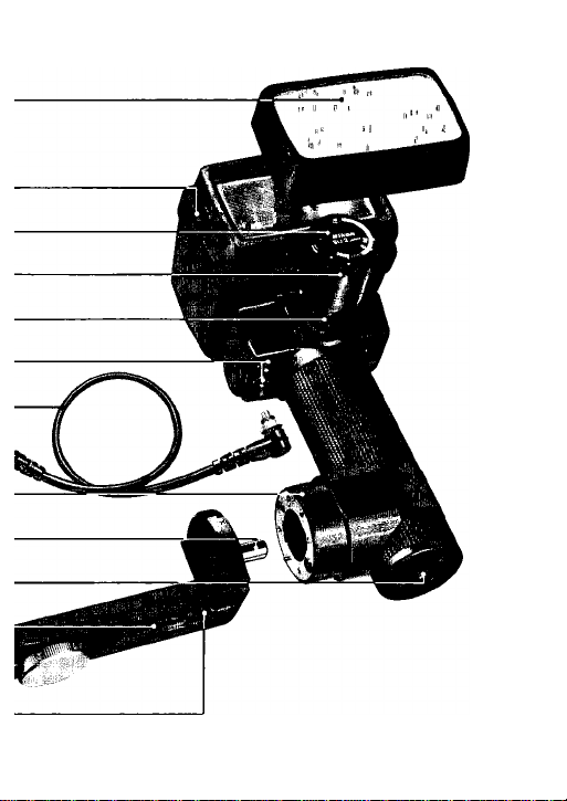
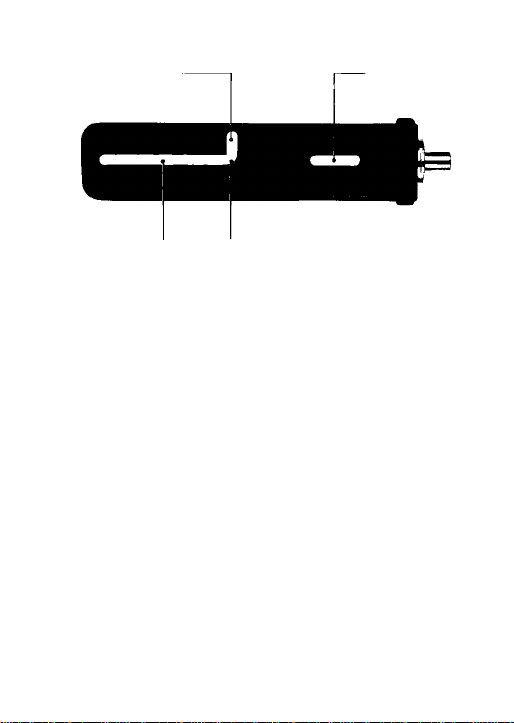
NOMENCLATURE
® Wide-Flash Adapter SW-5
@ Flash head
® Shooting mode selector
® Sensor Unit SU-2
® Sensor socket
® Sync/multiple flash sockets
@ Sync Cord SC-11
® Bracket mounting adapter
® Bracket mounting pin
@ Tripod/light stand socket
® Attachment screw slots
Bracket SK-5
@ Tripod socket
Page 3
Page 4
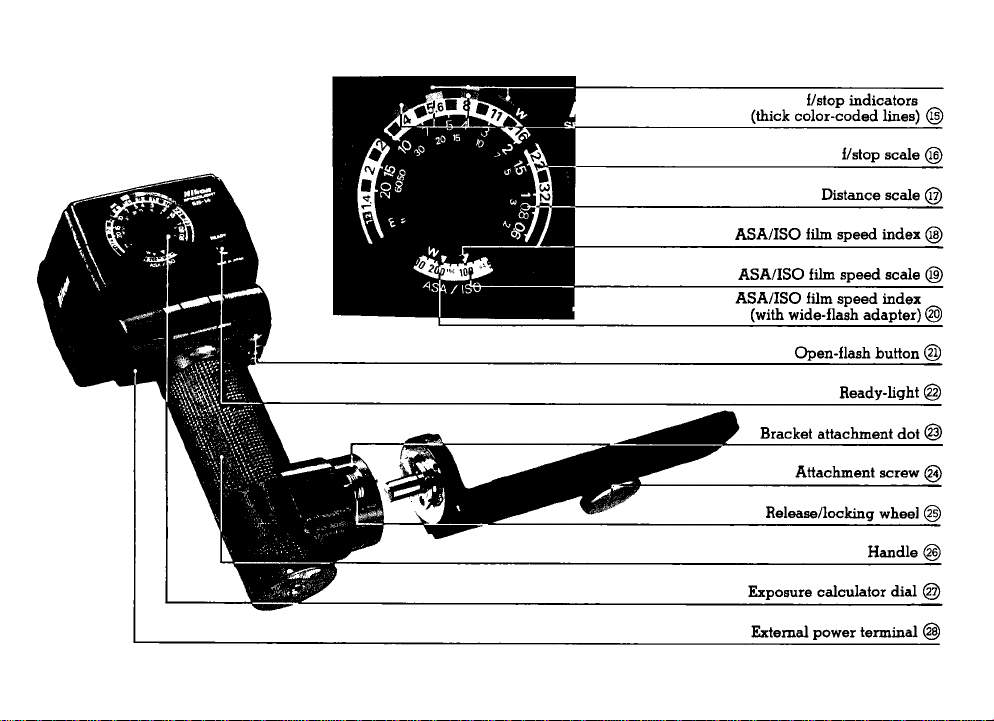
f/stop indicators with wide-flash adapter
(thin color-coded lines) @
Page 5

CON T E NT S
NOMENCLATURE
FOREWORD
BASIC OPERATION
CONTROLS IN DETAIL....................................10—20
Bracket SK-5
Bracket Mounting Adapter
Shutter Speed Dial................................................11
Exposure Calculator Dial
Sensor Unit SU-2..................................................15
Ready-Light..........................................................16
Open-Flash Button................................................17
Flash Head
Sync/Multiple Flash Sockets
Wide-Flash Adapter SW-5
TIPS ON AUTOMATIC FLASH SHOOTING
ACCESSORIES...................................................22—23
DCUnitSD-7
TTL Sensor Cord SC-12.......................................23
Sensor Remote Cord SC-13
Sync Cord SC-15..................................................23
"RED EYE" 24
OPTIMUM BATTERY PERFORMANCE
SPECinCATIONS........................................................26
- - - - - - - - - - - - - - - - - - - - - - - - - -
................................................
.................................................................
..............................................
........................................................
...................................
.............................
............................................................
................................
...................................
.........................................................
.................................
................
2—3
5—9
12—14
..........
10
10
18
19
20
21
22
23
25
4
Page 6

FOREWORD
The Nikon SpeedlJght SB-14 is a compact and light
weight electronic flash unit having a host of useful fea
tures.
With coverage matching that of a 28mm wideangle lens,
this unit uses a silicon-controlled rectifier and series
circuitry to provide automatic control of the flash ex
posure to match the camera-to-subject distance. In
addition, the SB-14 is able to conserve its excess energy
for the next shot when shooting subjects at close range,
thus reducing recycling time and increasing the number
of flashes per battery set. When the optional TTL Sensor
Cord SC-12 is used in conjunction with the Nikon F3 or F3
High-Eyepoint camera, the SB-14 provides automatic
through-the-lens control of flash exposure.
Moreover, the SB-14 allows complete creative control ot
bounce flash with its movable flash head which can be
tilted back 120° and rotated 120° to the right and 120°
to the left; click-stops are provided at 30°, 60°, 90°, and
120° intervals for both the tilting and rotating move
ments.
Even though the SB-14 is extremely easy to use, you
should familiarize yourself with the unit's basic operation
as presented in the first section. For more detailed in
formation, please refer to "Controls in Detail." A few
minutes wisely invested now will pay off later in years of
rewarding photographic experiences.
Page 7
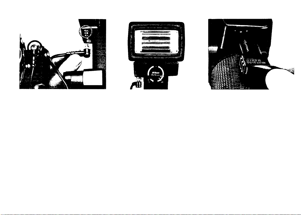
BASIC OPERATION
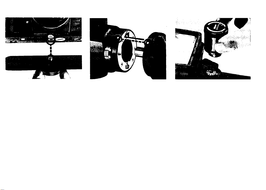
2 Attach the bracket @ to
* the camera.
Screw the bracket's attachment
screw @ into the camera's tripod
socket to secure the two units together
tightly. (For details, refer to page
10.)
2 Attach the bracket to the
* flash unit.
Insert the bracket mounting pin @
into the hole in the bracket mounting
adapter (s) with the two white dots @
aligned; rotate the camera forward
until it click-locks into place.
0^ Plug in the sensor©.
With the “Nikon" name facing toward
the flash head®, align the protrud
ing portion of the Sensor Unit SU-2
with the notched portion inside the
SB-14's sensor socket®; then push
the sensor into the socket until it
click-locks into place.
Page 8
BASIC OPERATION - continued
4, Attach the sync cord ©.
Screw one end of the Sync Cord SC-
11 into either of the flash unit's sync/
multiple flash sockets ® and screw
the other end into the camera's sync
terminal.
Nofe; Some cameras do not have the threaded
sync terminal.
Check the position of the
''•flash head.
Make sure that the flash head is in
the normal shooting position.
0^ Connect the power
• supply.
Plug the cord from the power supply
into the flash unit's external power
terminal®.
Note: The SB-14 is powered by only an external
power supply.
Page 9
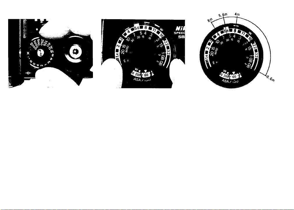
Set the camera's shutter
speed for proper syn
chronization.
Set the shutter speed dial to the prop
er synchronization speed for elec
tronic flash (e.g., set the F3 to the
“X" setting). For details, refer to the
chart on page 11.
Q Set the exposure calcu-
*lator dial®.
Turn the dial until the ASA/ISO film
speed index ® is opposite the number
for the speed of the film in use. The
three thick color-coded lines @
above the f/stop scale ® indicate the
three usable f/stops for automatic
operation and the distance scales @
below the usable f/stop scales give
you the range of flash-to-subject dis
tance. For example, if you're using
ASA/ISO 100 film, the usable f/stops
are f/4, below the orange line, f/5.6,
below the yellow, and f/8, below the
blue. The range of flash-to-subject
distance for each f/stop is 0.6m to
8m (2 to 26 ft.), 0.6m to 5.6m (2 to
18 ft.), and 0.6m to 4m (2 to 13 ft.),
respectively. (For more information
on selecting the f/stop, refer to "Ex
posure Calculator Dial" on page 12.)
Page 10
—BASIC OPERATION—continued*
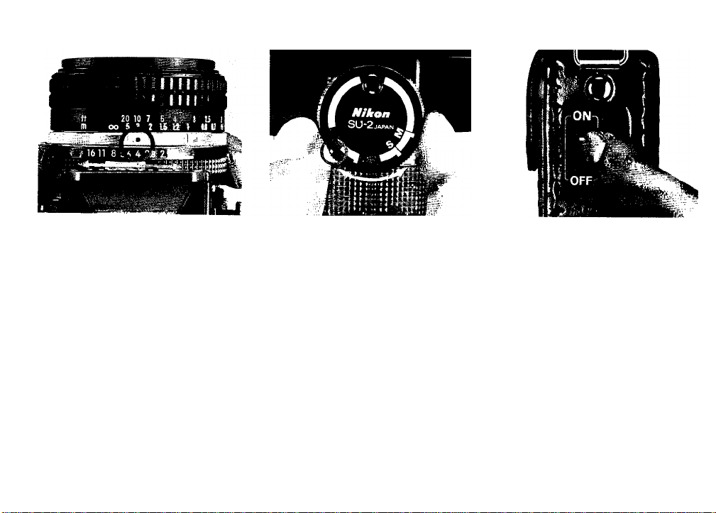
0^ Set the lens' aperture ring
to an appropriate
f / number.
In the example, f/4 is selected.
10. Set the shooting mode
selector
Turn the ring on the front of the sen
sor unit until the white index is op
posite the color corresponding to
that of the f/stop selected. (Orange is
selected in this example). This sets
the flash unit for automatic operation.
11. Turn on the power
* supply.
Page 11
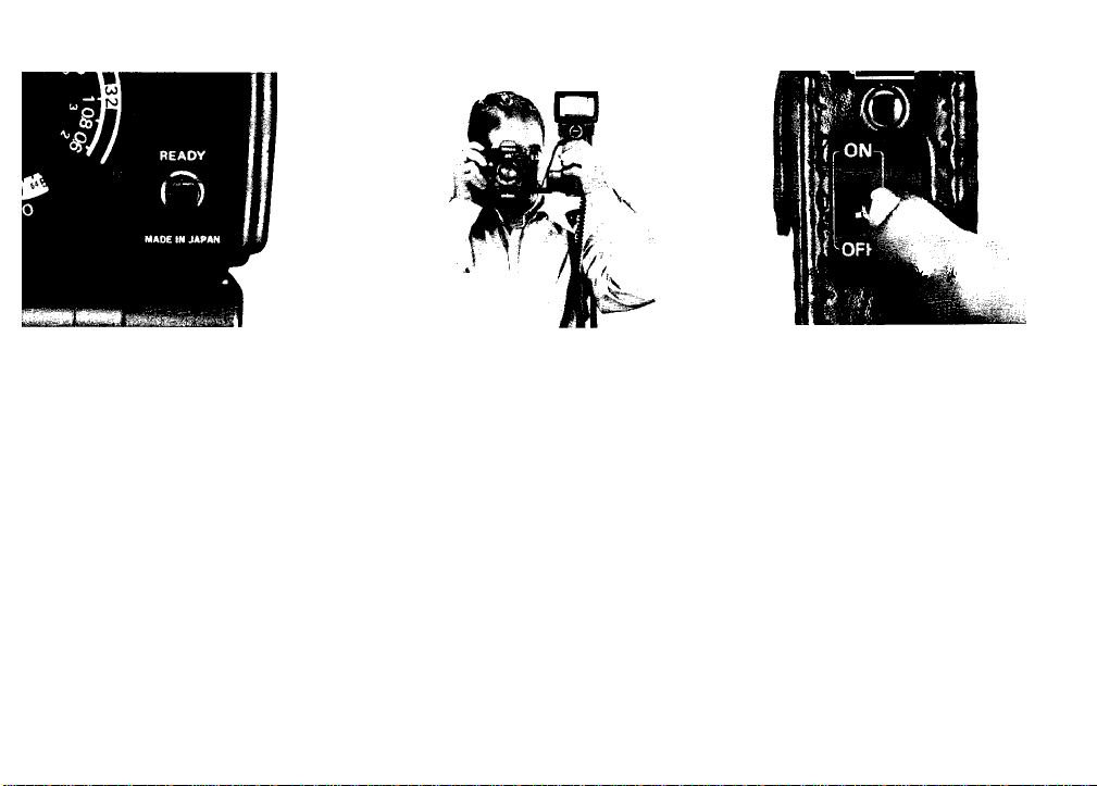
12. Watch the ready-light
As soon- as the LED ready-light
comes on, the flash unit is ready to
fire.
1 ' t
13. Take the picture.
When the shutter is tripped, the flash
unit fires and the picture is taken.
Soon, the ready-light will light up to
tell you the flash unit is recycled and
ready to fire again.
1
14. Turn off the power
* supply.
To conserve battery power between
shooting sessions, slide the power
switch of the power supply to the
OFF position.
Page 12
CX>NTROLS IN DETAIL
Nikon FE/FM2/FM Motor Drive MD-4
Motor Drive
MD-11/MD-12/MD-14 EM/F2,
-----
— Nikon F3/F3 High-Eyepoint/FG/
Motor Drive MD-2/MD-3/MD-E,
Cordless Battery Pack MB-l/MB-2
Bracket SK-5@
The Speedlight SB-14's bracket can be attached to various
camera and/or motor drive combinations. To change the
attachment screw from one slot (n) to another, slide it to
the threaded end of the slot and unscrew it; then screw it
back into the threaded end of the other slot. Once
screwed in, the attachment screw can be moved freely
to any position along the slot. The diagram indicates the
recommended position of the attachment screw for Nikon
SLR cameras and motor drives.
10
Page 13

Bracket Mounting Adapter ®
To detach the flash unit for off-camera flash operation,
push the release/locking wheel @ to the left and while
holding it, tip the flash forward until the two white dots
are aligned; then pull the flash unit away from the bracket.
Note: To detach the bracket mounting adapter from the flash unit's
handle use a standard screwdriver to loosen the two screws on the
face of the adapter.
Page 14

Shutter Speed Dial
To get proper synchronization, set the camera's shutter
speed dial as shown in the chart below. (For details, refer
to your camera's instruction manual.)
Synchronization chart
Camera type Shutter speed (sec.)
Nikon F3/
F3 High-Eyepoint
Nikon FE
Nikon FM2 X200 (1/200), 1/125 or slower
Nikon FM, EL2,
Nikkormat FT3
Nikon FG* P, A, M90 (1/90), 1/60 or slower
Nikon EM* AUTO or M90(l/90)
Nikon F2 series
*The Nikon FG and EM do not have a sync terminal. To use the SB-14,
you must attach the Sensor Remote Cord SC-13.
X(l/80), 1/60 or slower
M90(l/90), 1/125 or slower
1/125 or slower
1/80 (red line located between
1/60 and 1/125) or slower
Page 15

и
Page 16

—CONTROLS IN DETAIL-continued
Exposure Calculator Dial @
The exposure calculator dial on the back of the SB-14
helps you to select the usable range of f/stops for the
speed of the film in use and the flash-to-subject distance.
To set the ASA/ISO film speed, furn the dial until the
number corresponding to the film speed is opposite the
ASA/ISO film speed index. Set the film speed to the “W"
index mark @ when the Wide-Flash Adapter SW-5 ® is
attached to the flash unit.
Note: Dots between the numbers on the him speed scale ^represent
intermediate settings. (See illustration.)
12
800
640
500
400
320
250
200
’ 100
80 40
50
125
For Automatic Operation
With the Sensor Unit SU-2 attached to the Speedlight
SB-14, you can shoot on Automatic. Three usable f/stops
are indicated by the thick color-coded lines after you set
the ASA/ISO film speed on the dial.
For example, if you are using ASA/ISO 100 film, you can
select either f/4, f/5.6 or f/8. In selecting the f/stop, the
flash-to-subject distance, recycling time, and depth of
field are important factors.
• Flash-to-subject distance
The thick color-coded lines indicate the range of flash-tosubjecf distances for automatic shooting as well as the
usable f/stops. Each distance range is constant regardless
of fhe film speed set on the dial. The orange line indicates
26
a range from 0.6m fo 8m (2 to 26 ft.), the yellow from
0.6m to 5.6m (2 to 18 ft.), and the blue from 0.6m to 4m
(2 to 13 ft.). So, for example, wifh ASA/ISO 100 film and
Page 17

ti 6П'
a subject more than 5.6m (18 ft.) away, the only usable
f/stop is f/4.
On the other hand, the thin color-coded lines (3)with "W"
indicate the distance ranges when the wide-flash adapter
is used: from 0.6m to 5.6m (2 to 18 ft.), 0.6m to 4m (2 to
13 ft.), and 0.6m to 2.8m (2 to 9 ft.), respectively. In this
case, with ASA/ISO 100 film, if the subject is more than
4m (13 ft.) away, only f/4 can be used.
Note: With a subject more than 8m (26 it.) away — or more than 5.6m
(18 ft.) away when using the wide-flash adapter — shoot on manual.
• Recycling time and depth of field
If the subject distance remains the same, the wider the
aperture you select, the faster the recycling time of the
flash unit and the greater the maximum shooting distance,
but the less the depth of field. With ASA/ISO 100 and a
subject up to 4m (13 ft.) away, you can select any one of
the three f/stops indicated, f/4, f/5.6 or f/8, taking into
consideration the recycling time or depth of field you
desire. With the wide-flash adapter attached and a sub
ject up to 2.8m (9 ft.) away, the usable f/stops are also
f/4, f/5.6 and f/8.
13
Page 18

—CONTROLS IN DETAIL-continued
For Manual Operation
Set the ASA/ISO dial and simply read off the f/number
which appears directly above the flash-to-subject dis
tance; then set this aperture on your lens.
For example, with ASA/ISO 100 and a subject 2m (approx.
7 ft.) away, the usable f/stop is f/16 without wide-flash
adapter, or f/11 with the wide-flash adapter attached.
Without referring to the exposure calculator dial, you
can also determine the f/stop by using the following eguation:
f/stop =
With ASA/ISO 100 film and meters, the SB-14's guide
number is 32. If the subject is 8m away, divide 32 by 8 to
get f/4.
14
guide number
flash-to-subject distance
Caution: For manual operation, be sure to set the shooting mode selector
ol the Sensor Unit SU-2at the "M"position.
Page 19

Sensor Unit SU-2
The Sensor Unit SU-2 controls the operation of the SB-14.
It has five settings to choose from.
At the Three Auto Positions
To shoot on Auto, lift up and turn the knurled ring on the
outside of the sensor to one of the three positions (orange,
yellow, or blue) which are color-coded for use with the
exposure calculator dial. At these settings, the SB-14 is
able to vary its light output automatically to match the
flash-to-subject distance.
At the S (Slave) Position
At this setting, the SB-14 emits a modulated burst of light
which can trigger a second electronic flash. The remote
flash unit is connected to the receiver portion of the
optional Modulite Remote Control Unit ML-1 (which is set
to channel 2), while the Speedlight SB-14 acts as the
transmitter.
0
Page 20

Note: Although the SB-14 operates with maximum light output at the S
position, be sure to set the camera's shutter speed dial at slower than the
ordinary synchronization speed. For example, if the camera's synchro
nization speed is 1/125 sec., set the shutter speed at 1/60 sec. orslower.
At the M (Manual) Position
Set the SU-2 to the M setting and the SB-14 operates
manually at its maximum light output regardless of the
flash-to-subject distance. In this case, you have to calcu
late the exposure manually by referring to the exposure
calculator dial.
Detaching the Sensor Unit
To detach the SU-2, push in the two protrusions at the
base of the sensor and pull it out.
15
Page 21

CONTROLS IN DETAIL-continued
Ready-Light (
Built into the back of the SB-14's flash head is a readylight which comes on as soon as the flash unit is recycled
and ready to fire. As an additional feature, the readylight blinks if the flash fires at its maximum output indi
cating that the light might be insufficient for correct
exposure on Automatic. The warning blinks last for ap
proximately two seconds. In this case, reset the lens aper
ture to the proper f/stop.
Note:
1) With a subject near the hr limit of the usable shooting range, it is
2) When the batteries are nearly exhausted, the light output of the
recommended to wait a few seconds after the ready-light comes on
before taking the shot.
flash unit decreases.
16
Page 22

Open-Flash Button @
The red open-flash button is used to fire the flash unit
manually without having to trip the camera's shutter. In
this manner, you can create multiple-exposure "strobo
scopic" effects or paint the scene with light by firing
the flash repeatedly with the camera set to "B." However,
with the SB-14 connected via a sync cord to the camera
set at "B," the flash will not go off even when the open-
flash button is pushed. So, make sure to remove the con
necting cord from the camera before using the openflash button.
The open-flash button is also used in conjunction with the
ready-light to determine if you can get the correct ex
posure when shooting on automatic. This is especially
useful when doing bounce flash. After setting up the shot,
push the open-flash button. If the ready-light does not
blink, you can take the picture. If it does blink, try
moving the flash closer to the subject or bounce surface.
Page 23

or reset the Sensor Unit SU-2 to a color-coded position
calling for a wider aperture.
17
Page 24

CONTROLS IN DETAIL-continued
Flash Head®
The SB-14's movable flash head can be tilted back up
to 120° and rotated 120° to the left and 120° to the right;
click-stops are provided at 30°, 60°, 90° and 120° for
both tilting and rotating movements. For normal shooting,
point the flash head straight ahead. In this position, the
light travels directly out to the subject providing the
maximum amount of light possible. However, to soften
the shadows and lower the contrast for indoor snapshots,
you can tilt the flash head up and simultaneously rotate
it to the left or right to bounce the light off the ceiling or
walls. Consult the illustration for details. Note that unless
the surface you are using to bounce the light off of is
white or silver, your color photographs will come out
with an unnatural color cast similar to that of the reflect
ing surface.
The color temperature of the SB-14's light output is
balanced for use with daylight type color film.
18
Note: When the flash head is tilted up to 120°, rotation is somewhat
restricted; and depending on the amount of rotation, tilt might be re
stricted.
Page 25

Sync/Multiple Flash Sockets ®
Two standard Nikon screw-type terminals are provided
on the Speedlight SB-14. Either terminal can be used to
connect the SB-14 to the camera, while the other is pro
vided for connecting the SB-14 with another flash unit in
series for multiple flash operation. When using the Nikon
Speedlight SB-11, 12, 14 or 15 as a secondary unit, con
nect the flash units together using the Sync Cord SC-11
or SC-15. With the SB-10 or SB-7, use the Sync Cord SC5, SC-6 or SC-7.
Note: In multiple flash operation, make sure to use both flash units on
manual.
Page 26

19
Page 27

—CONTROLS IN DETAIL-continued
Wide-Flash Adapter SW-5
0
The angle of illumination of the SB-14 by itself covers the
picture angle of a 28mm wideangle lens. When the wideflash adapter is attached onto the front of the flash head,
it increases the illumination from 67° to 77° horizontally
and 48° to 56° vertically, providing just the right amount
of coverage when a 24mm lens is used.
20
Note: With the SW-5 attached, the light output of the flash unit is
reduced, resulting in a decrease in guide number from 32 to 22 (ASA/ISO
100 and meters) or 52 to 36 (ASA/ISO 25 and feet). Automatic shooting
ranges with ASA/ISO 100 decrease to 0.6m to 5.6m (2 to 18 ft.) at f/4,
0.6m to 4m (2 to 13 ft.) at f/5.6 and 0.6m to 2.8m (2 to 9 ft.) at f/8.
Page 28

TIPS ON AUTOMATIC FLASH SHOOTING-
Subject's Reflectivity
When you shoot a dark subject (one with low reflectivity),
reduce the aperture selected by one-half to one full f/stop.
When the subject is light in tone (has high reflectivity),
reset the aperture so that it is one-half to one full f/stop
wider. Otherwise, your pictures might come out over-
or underexposed.
If you photograph a subject of very high reflectivity, such
as when shooting directly into a mirror or metallic sur
face, underexposure is certain to occur. In this case,
take pictures on manual.
Sensor Unit SU-2
The sensor reads the light reflected from the subject. If
something, such as the sync cord or your finger, comes
between the sensor and the light reflected from the sub
ject, the SB-14 will be unable to deliver the correct ex
posure.
Fill-In Flash Photography
In fill-in flash photography with a very bright back
ground, overexposure might occur. Make sure that the
scene's brightness does not exceed the exposure value
determined by the combination of shutter speed you set
and aperture selected.
21
Page 29

ACCESSORIES
-----------------------------
DC Unit SD-7
Accepting six C-type batteries, the SD-7 is designed to
be used as a power source for both the Nikon Speedlights
SB-14 and SB-11. It has a neckstrap for convenient use.
22
Page 30

TTL Sensor Cord SC-12
One meter long, this cord allows the SB-14 to be used
with the Nikon F3 or F3 High-Eyepoint camera for auto
matic through-the-lens control of the flash exposure.
When attached, the camera's shutter speed is auto
matically switched to the proper flash synchronization
speed of 1/80 sec. with the shutter speed dial at A or
1/125 sec. and above. The ready-light inside the camera's
viewfinder also operates in the normal manner.
Sensor Remote Cord SC-13
Also one meter long, the SC-13 allows mounting of the
SB-14's Sensor Unit SU-2 directly on the Nikon FE, FM2,
FM, FG, or EM's hot shoe for automatic, off-camera
operation with the flash unit pointed in any direction.
With the Nikon F3 or F3 High-Eyepoint camera, the Flash
Unit Coupler AS-4 is reguired and control of the flash
exposure is automatic, but not through-the-lens.
Sync Cord SC-15
A coiled cord over one meter in length, the SC-15 screws
into the camera's sync terminal and allows the SB-14 to
be detached from its bracket and used off-camera.
Page 31

23
Page 32

"RED EYE'
"Red eye," an optical phenomenon in which a subject's
eyes appear red in photographs taken with a flash
unit, is a result of the flash light's directly illuminat
ing the retina. This happens when the subject looks
straight into the camera on which a flash unit is
mounted. The effect becomes more pronounced if
there is little or no ambient light. In this case, the pupil
of the eye is wide open, and the illuminated retina is
clearly visible.
To avoid "red eye" you can take any or all of the follow
ing steps:
1. Brighten the room to minimize the opening of
the subject's pupils.
2. Instruct the subject not to look straight into the
camera.
3. Keep the flash unit as far away as possible from
the camera by means of a sync cord.
Note that once “red eye" appears, there is no way of
retouching the negatives.
24
Page 33

Page 34

OPTIMUM BATTERY PERFORMANCE
1. New batteries: Between manufacturing and first
use, all batteries exhibit some drain. Therefore,
care should be taken to purchase the newest
(and freshest) ones possible. To help you do this,
some manufacturers stamp the date of manu
facture on the bottom of each battery. Ask your
camera dealer for assistance in interpreting the
codes.
2. Temperature: Battery life ratings are based on
operation at around 20°C (68°F). At other tem
peratures, battery life is shortened. At 0°C, for
instance, battery life is shortened by as much as
2/3. Spare batteries should therefore be kept
available if operation in low temperatures is
anticipated.
3. Continuous use: Batteries are drained much
more quickly by continuous use than by inter
mittent use.
4. Storage: When not in use, the batteries should
be removed to prevent damage from leakage. To
minimize drain during the period of disuse,
store the batteries in a cool, dry place.
Battery brands: Do not use mixed brands of
batteries, nor batteries with different model
numbers. Also, avoid mixing new and old bat
teries since proper performance will not be ob
tained and battery leakage may occur.
6.
Disposal: Do not dispose of batteries by burning.
Also, for safety's sake, do not disassemble bat
teries when disposing.
7.
Polarity: When installing batteries, observe the
voltage polarities carefully. Reversal of the posi
tive (-I-) and negative (—) terminals will result
in leakage.
25
Page 35

SPECinCATIONS
Guide number
(ASA/ISO 100 and meters) 32 (22 with Wide-Flash
Adapter SW-5)
(ASA/ISO 25 and ieet)
52 (36 with Wide-Flash
Adapter SW-5)
Angle of coverage
Horizontal: 67° (77° with
SW-5)
Vertical: 48° (56° with SW-5)
Power source
Battery Pack SD-7 holding
six C-type batteries
Battery Number of flashes
1.2V rechargeable NiCd
batteries
1.5 V alkaline-manganese
batteries
1.5V manganese batteries approx. 80 times less than 12 sec.
approx. 100 times less than 4 sec.
approx. 270 times
Usable f/stops and automatic shooting range
Film sensitivity
Position of
shooting mode
selector
Orange 2
Yellow
Blue 4 5.6 8 11 16 22
(ASA/ISO)
2S|50|100|200|400|800
f/stop
2.845.6 8 11
2.845.6 8 11 16
Normal
operation
(2.0~26.2)
0.6~5.6
(2.0~18.4)
0.6'^4
(2.0~13.1)
Recycling time
less than 9.5 sec.
Unit; m (feet)
Auto shooting range
With Wide-Flash
Adapter SW-5
0.6~5.6
(2.0~18.4)
0.6~4
(2.0^13.1)
0.6~2.8
(2.0~9.2)
26
Page 36

Dimensions
Weight
Accessories provided
Approx. 217mm(H)x
94mm(W)x91mm(D)
Approx. 515g (with the
Sensor Unit SU-2)
Approx. 290g (Bracket
SK-5 only)
Sensor Unit SU-2
Bracket SK-5
Wide-Flash Adapter SW-5
Sync Cord SC-11
Page 37

27
Page 38

No reproduction in any form of this booklet,
in whole or in part (except for brief quotation in
critical articles or reviews), may be made without
written authorization from the publisher.
iMikoti)
NIPPON KOGAKU K.K.
Printed in Japan (82.7.0 &-3
 Loading...