

Page 1
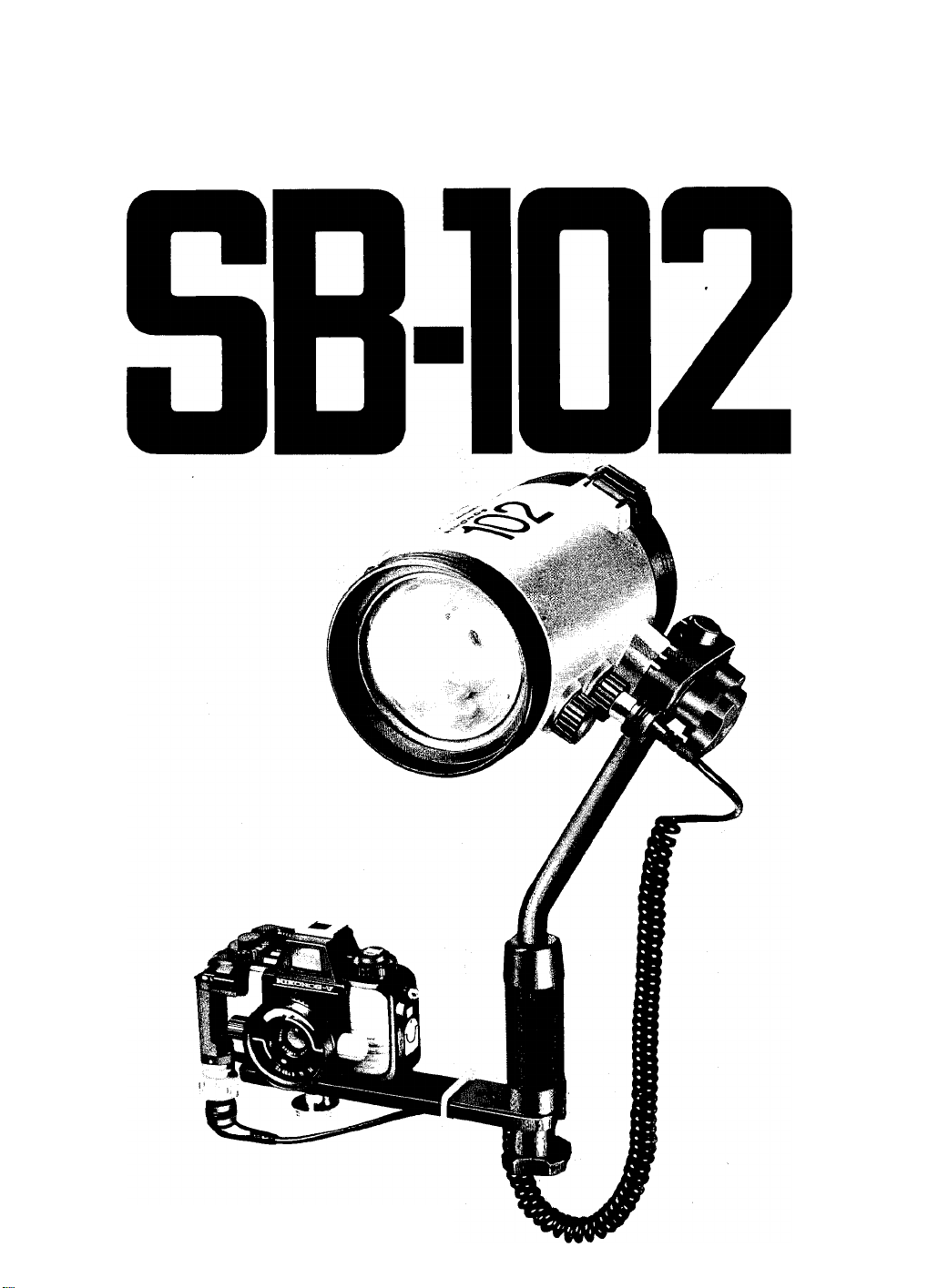
Mikon
Speedlight
INSTRUCTION MANUAL
Page 2
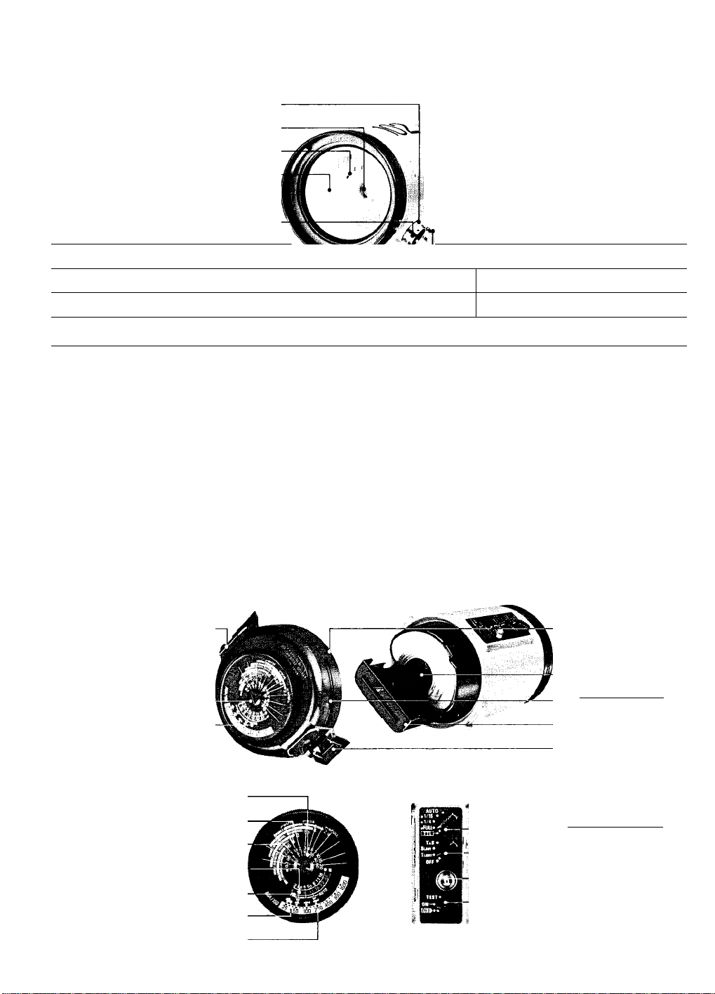
NOMENCLATURE
0 Synchro socket index
) Sensor socket index
> Target-iight lamp
) Slave sensor
I Firing tube
Wide-Fiash Adapter
) SW-102
) Sensor socket
I Synchro socket
(D Synchro socket cover
® Sensor socket cover
(D) Spare target-light lamp
(!|) Speedllght plug and locking ring
) Sync cord
1 Camera piug and locking ring
) Sensor hoider socket
) Sensor hoider positioning pin
I Bracket slot
I Bracket screw
Joint coilar
Flash head positioning index
Joint plate
"0.3m" position mark
"0.6m” position mark
"Normai” position mark
Arm positioning index
Joint iever
Arm positioning screw ®
Joint @
I
_________________________
M
0-rings and iubricant
fJW Arm ®
Grip
o
I Tripod socket
I Cord fastening hanger
) Bracket
) Buckie iock/reiease iatch
) Exposure caicuiation diai screw
) Exposure caicuiation dial
Exposure calculation dial
@ Distance scaie
) Aperture scale
) Distance iines
) Non-TTL auto shooting aperture scale
) Non-TTL auto shooting aperture index
) Shooting situation marks
) ASA/ISO film speed scale
Arm knob
Battery chamber cap index
Target-light holder
Battery chamber cap
C-type battery cartridge
Buckle
Shooting mode selector
T-S switch
Ready-light
Power switch
Page 3

CONTENTS
NOMENCLATURE
FOREWORD...................................................................... 4
PREPARATION........................................................... 4—6
Examining and iubricating the O-rings
The O-rings and their sealing method
TIPS ON SPEEDLIGHT CARE
BASIC OPERATIONS
CONTROLS IN DETAIL..............................................17-30
Bracket
.....................................................................
Arm............................................................................ 17
Joint
..........................................................................
Close-Up Shooting in the Non-TTL
Automatic Mode
Synchro Socket
Sensor Socket.......................................................... 19
Sensor Unit SU-101 (Optional]
Synchronization Speed
Shooting Mode Selector
Exposure Calculation Dial
TTL Automatic Flash Control
Non-TTL Automatic Flash Control
Manual Flash Control........................................25—26
Exposure Compensation..................................26—27
Ready-Light........................................................27—28
Test Firing................................................................. 28
Cord Fastening Flanger........................................... 29
Wide-Flash Adapter SW-102
Target-Light........................................................29—30
Multiple Flash Photography
Daylight Fill-In Flash Photography......................... 30
TIPS ON SPEEDLIGHT PHOTOGRAPHY
OPTIMUM BATTERY PERFORMANCE
ACCESSORIES
Sensor Unit SU-IOI
Sensor Fielder (for SB-102]
Extension Arm.......................................................... 33
Double Flash Bracket............................................... 33
Double Sync Cord
Protectors.................................................................. 34
Speedlight Case SS-101 (Provided]........................ 34
O-rings and Lubricant.............................................. 34
SPECIFICATIONS............................................................ 35
...........................................................
__________
............................................................
...................
.....................
.........................................
..................................................
....................................................
.......................................................
...............................
...........................................
.........................................
......................................
...........................
.........................
...................................
....................................
.....................
.........................
..................................................
.....................................
....................................................
22—23
33-34
8-16
17
18
18
19
20
20
21
22
24
29
30
31
32
33
33
34
2
5
6
7
Speedlight Case SS-101
Page 4

FOREWORD
The Nikonos Speedlight SB-102, an amphibious high
performance electronic flash unit with a silicon-con
trolled rectifier and series circuitry, is designed for use
with the Nikonos-V, Nikonos IV-A, and Nikonos III. The
SB-102 can be submerged to a depth of 50 meters
(160 feet) and withstand pressure of up to 6kg/cm^
(85 Ib/in^), enabling it to be used in environments where
regular speedlights could not be taken.
In combination with the Nikonos-V, the SB-102 features
automatic through-the-lens (TTL) flash exposure con
trol. This means the silicon photodiode (SPD) in the
Nikonos-V’s shutter box reads the light passing through
the lens and then automatically signals the speedlight
to turn itself off when the exposure is correct. Because
TTL flash offers a wide range of useable apertures and
shooting distances, depth of field is easy to control and
shooting as close as 0.3 m (1 ft) is possible.
With the optional Sensor Unit SU-101, the SB-102 can
be used for non-TTL automatic flash photography in
combination with the Nikonos-V, Nikonos IV-A, and
Nikonos III. In this mode, flash output is automatically
controlled by the SU-101.
This speedlight has the same area of coverage as a
28mm lens. When the Wide-Flash Adapter SW-102
(provided) is used, the area of coverage increases to
that of a 15mm lens.
The SB-102 also features manual control with three
power settings (“FULL," “M1/4,” and “M1/16”), slave
firing capability for wireless multiple flash photography,
and a target-light for close-up shooting. The target-light,
positioned in the center of the flash head, shoofs a
beam of light at the subject to help you aim the flash
head at the subject. In addition to the equipment men
tioned, a variety of optional accessories is available to
increase the versatility of the SB-102.
Even though this speedlight is extremely easy to oper
ate, you should still familiarize yourself wifh the pre
paratory steps and basic operations explained in the
first two sections of this manual. For more detailed
information, refer to “CONTROLS IN DETAIL” and
“TIPS ON FLASH PHOTOGRAPHY A few minutes
wisely invested now will pay off later in years of reward
ing photographic experiences.
PREPARATION
STOP! READ THIS NOTICE BEFORE USING YOUR SB-102. THE 0-RING SEALS
MUST BE EXAMINED AND LUBRICATED BEFORE USE TO AVOID DAMAGING
THE SPEEDLIGHT.
This Nikonos Speedlight SB-102 uses 0-rings to seal
and waterproof the junctions between parts. Your
Nikonos Speedlight SB-102 should not be considered
waterproof until you have examined the user-service
able 0-rings (one each for the battery chamber cap®,
the sync cord's ® camera and speedlight plugs, and
the synchro socket and sensor socket covers (|) @).
They must be in perfect, undamaged condition and
properly lubricated prior to each use. Read the follow
ing instructions thoroughly to familiarize yourself wifh
the maintenance of fhe 0-rings.
Because fhe outer surface of your Nikonos Speedlight
SB-102 has been specially treated to make it water
proof, it must be protected from impacf. If it becomes
damaged, send it to a qualified technician for service
before the next use.
Your Nikonos Speedlight SB-102 is watertight only when
In perfectly serviced condition, when all 0-ring seals
are in perfect condition, and when all components are
properly assembled and closed.
Pay special attention to the instructions for installing
the O-rings because they are what make the Nikonos
Speedlight SB-102 watertight. For the O-rings to per
form properly, fhey must be in perfect condition (with
no cuts, tears, or other imperfections) and properly
lubricated. If fhey are nof, they will not perform properly
and may allow water to enter your flash unif. To prevent
the accidental use of a defective 0-ring, always discard
old rings.
The channels into which the O-rings fit must be free of
anyforeign matter and in their original, smoothly finished
condition. If they are not, the O-rings will not seat pro
perly and may allow water to enter your flash unit. If any
channel in your Nikonos Speedlight SB-102 becomes
damaged, send the unit to a qualified technician for
service before the next use.
Your Nikonos Speedlight SB-102 contains a series of
O-rings. Some are factory-installed and cannot be
serviced by you. Once each year, send your fiash unit
to a qualified technician so that these O-rings can be
serviced. Do not attempt to disassemble the unit and
service these O-rings yourself.
All of the O-rings in your Nikonos Speedlight SB-102
that can be serviced by you must be examined at the
end of each dive day and, if possible, after each dive.
Page 5
PREPARATION —continued
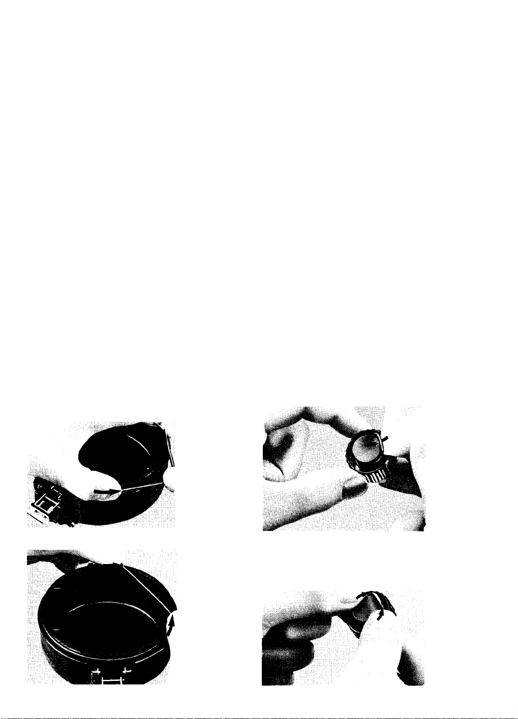
Examining and lubricating the 0-rings:
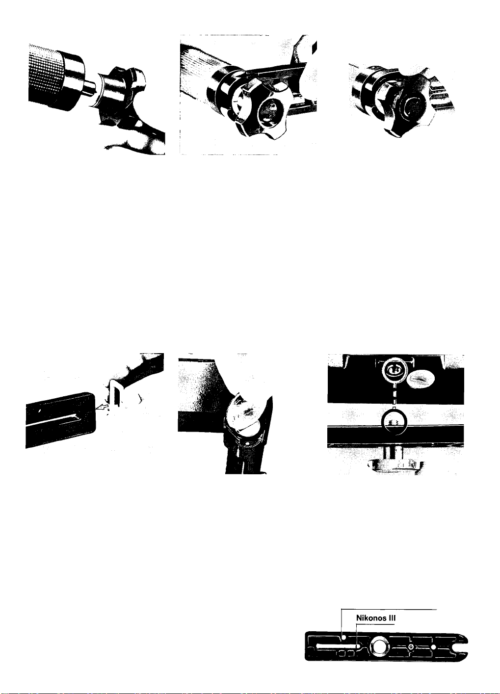
1. To remove the 0-rings, except those in the synchro
socket and sensor socket covers, grasp the ring be
tween your thumb and forefinger. Pinch your fingers
together as you slide them in the direction of the
arrow to create slack in the 0-ring. Then grasp the
slack portion with your other hand and pull the ring
off (see Fig. 1).
To remove the 0-rings in the synchro socket and
sensor socket covers, use the edge of a credit card
or dive card or some thin, blunt, instrument. Never
use a knife or other sharp-edged object. Push up
on the center of the cover with a fingertip (or pointed
object), insert the card under the ring, and puli it up
to lift the 0-ring out (see Fig. 2). Do not scratch the
0-ring in the process.
2. Visually examine each 0-ring for imperfections. If
any 0-ring is damaged (by tears, cuts, or other im
perfections), discard it immediately. If any 0-ring has
dirt, sand, hair, or foreign matter on it, rinse the 0-ring
in fresh water to remove it.
3. When lubricating the various parts of your flash unit,
use only the special non-water-soluble silicone
lubricant supplied with the speedlight. Never use
other lubricants (such as Vaseline) which are watersoluble.
4. To lubricate the 0-rings, smear a small amount of the
special silicone lubricant on your fingertips and then
gently run each 0-ring between your fingertips.
Never use a brush or similar object to apply the lubri
cant; small hairs may fall into the channel and allow
water to enter the flash unit. While lubricating each
0-ring, examine it with your fingertips for imperfec
tions. If an 0-ring is properly lubricated, it will glisten
and will not have "gobs” of lubricant on it.
To ensure the longest possible flash unit life, apply
lubricant whenever necessary. Lubrication protects
the 0-rings from excessive wear; it also makes it
easier to attach or remove other parts.
5. Visually examine the channels into which the 0-rings
fit to determine that each is clean and smooth. If any
channel is dirty, clean it with a non-lint-bearing mate
rial. Coat each channel with a thin film of lubricant
while being careful not to apply too much.
6. Reseat all of the 0-rings with your fingertips by insert
ing one side of the ring into the channei and holding it
in position while rolling the other side of the ring into
piace (Fig. 3). To insert the 0-rings into the channels
of the synchro socket and sensor socket covers,
push up on the center of the cover with a fingertip
(or pointed object), piace the ring over the channel,
then press it down into place. Check that the 0-ring
is not twisted and that each of its edges is properly
seated (see Fig. 4).
7. Check the surfaces which are opposite the 0-rings
to determine that each is clean, smooth, and free of
foreign matter. Clean and lubricate the surfaces in
the same manner as the channels.
8. When reattaching the parts with 0-rings, be sure that
each 0-ring seats properly and securely. All of the
0-rings must be properly aligned and not “pinched."
Fig. 1
Fig. 3
V
Fig. 2
Fig. 4
Page 6
PREPARATION —continued.
The preceding instructions must be performed on each
user-serviceable 0-ring prior to each dive day and, if
possible, prior to each dive. By following these pro
cedures and all other procedures in this instruction
manual, you will be able to enjoy using your Nikonos
Speedlight SB-102 for many years.
Reminder; An extra set of 0-rings and a tube of lubri
cant are supplied with the flash unit. Additional 0-rings
and lubricant are available from authorized Nikon
dealers and service centers.
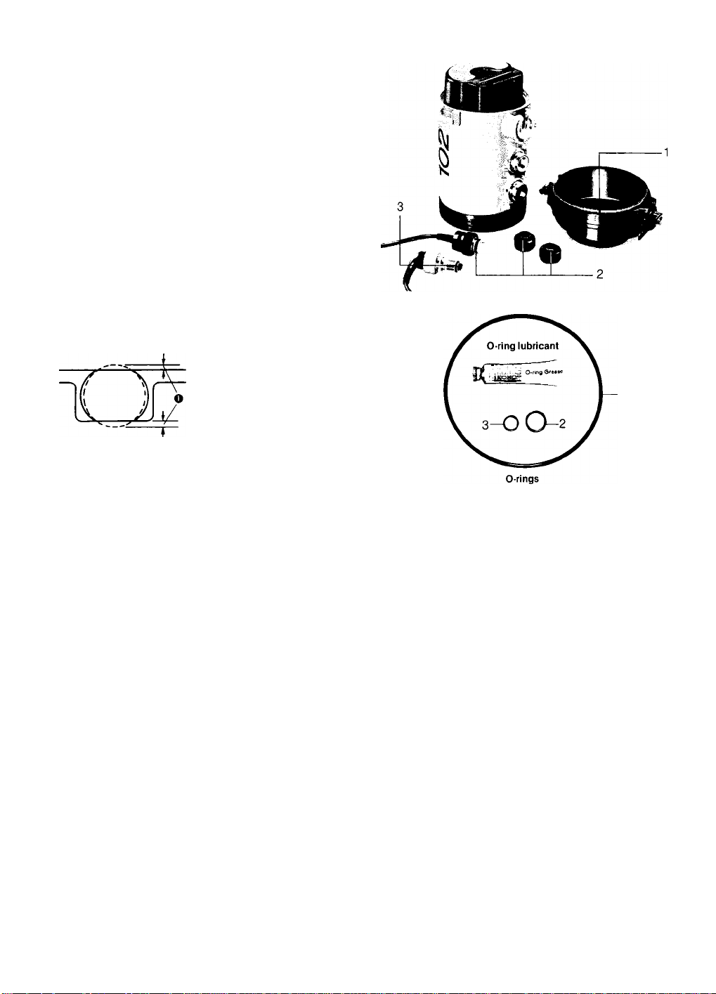
The 0-rings and their seaiing method
The method used by the 0-rings to seal and waterproof
the flash unit is shown in the following illustrations.
When a low level of pressure exists (for instance, just
under the water’s surface), each 0-ring seals its groove
by its own elastic force (see Chart A). When the pres
sure increases (at greater depths), the 0-ring’s shape
is altered and its sealing ability is increased to withstand
the greater pressure. The pressure changes the ring
from its original “0” shape (when looking at a cross
sectional view) to a ','D” shape (see Chart B).
Pressure
Chart A
O Slight compression
Chart B
Page 7
TIPS ON SPEEDLIGHT CARE
1. After using the speedlight and camera under
water, rinse them both as soon as possibie in
fresh running water with the sync and sensor
cords attached. When the speediight/camera
assembly gets dirty, rinse it thoroughly in fresh
water. Immediately after using it in salt water,
rinse it thoroughly in fresh water to remove any
residue. Otherwise, corrosion may occur in
minute places like small holes or the junctions
of parts. To prevent this, soak the speedlight/
camera assembly overnight in a basin of fresh
water, then rinse it vigorously in running water
while paying special attention to the joint @, arm
@, bracket screw®, buckles®, and similar parts
where it is very difficult to remove mud or salt.
Finally, dry the speediight/camera assembly with
a soft cloth—never by heating—before removing
the sync and sensor cords. Be sure to wipe away
any drops of water that may have speeded in
past the 0-ring.
When the unit is completely dry, check the
0-rings. If any of them is scratched or damaged,
immediately replace it with a new one by follow
ing the procedures in “PREPARATION.”
All moving parts should be lubricated to prevent
corrosion and facilitate attachment. Apply lubri
cant sparingly and be sure to wipe off any excess.
When the speedlight will not be used for some
time, store it in a cool, dry, clean place with the
batteries and battery chamber cap removed.
2. Never submerge the speedlight in water with
the sync or sensor socket cover removed, or
get the sync or sensor cord plugs wet. Always
make sure the sync cord and sensor cord plugs
are securely attached before entering the water.
3. Never pick up or suspend the speedlight by the
sync or sensor cords.
4. If an 0-ring with dust, scratches, or damage is
used, water may enter the flash unit and damage
the electrical circuitry. Before and after diving,
check the 0-rings by following the procedures
in PREPARATION
5. Do not allow the speedlight to be exposed to
direct sunlight for long periods. And never place
the speedlight in an area where the temperature
is or may rise to 60°C (140°F) such as in a
closed car or car trunk during warm weather.
6. Fligh-voltage circuitry may cause electrical
shock if water enters the flash unit. Should water
get inside the flash unit, take it—with the bat
teries and battery chamber cap removed—to
an authorized Nikon dealer or service center
immediately.
If you experience difficulty of an electrical nature
with the unit, never attempt to disassemble or
service it yourself. Instead, take the unit to an
authorized Nikon dealer or service center.
7. As much as possible, avoid removing the battery
chamber cap near salty wind or splashing water
because either may damage the unit’s electrical
circuitry. If the battery chamber cap must be
removed in one of these situations, for instance,
to exchange batteries, use a vinyl bag to prevent
water or salt from entering the unit.
8. When not using the speedlight, remove batteries
to prevent damage from battery leakage. Leaking
batteries may also cause dangerous combustible
gases to be trapped inside the battery chamber.
If the battery chamber becomes corroded by
leakage, take the unit to an authorized Nikon
dealer or service center.
9. To remove dirt or fingerprints, wipe with a soft,
dry or silicon-treated cloth. Never use thinner,
benzine, or alcohol because they may damage
plastic parts. To clean the Wide-Flash Adapter
SW-102, wash it with soap and water. Never
use a brush.
10. If this speedlight is frequently used underwater
(especially in salt water or dirty water), take it to
an authorized Nikon dealer or service center for
inspection on a regular basis.
11. If the speedlight is dropped or bumped against
a hard surface, take it to an authorized Nikon
dealer or service center for inspection even if
there is no surface damage.
12. After using the speedlight, attach the dust-proof
plastic caps to the sync and sensor cord plugs
to protect them from damage.
Page 8
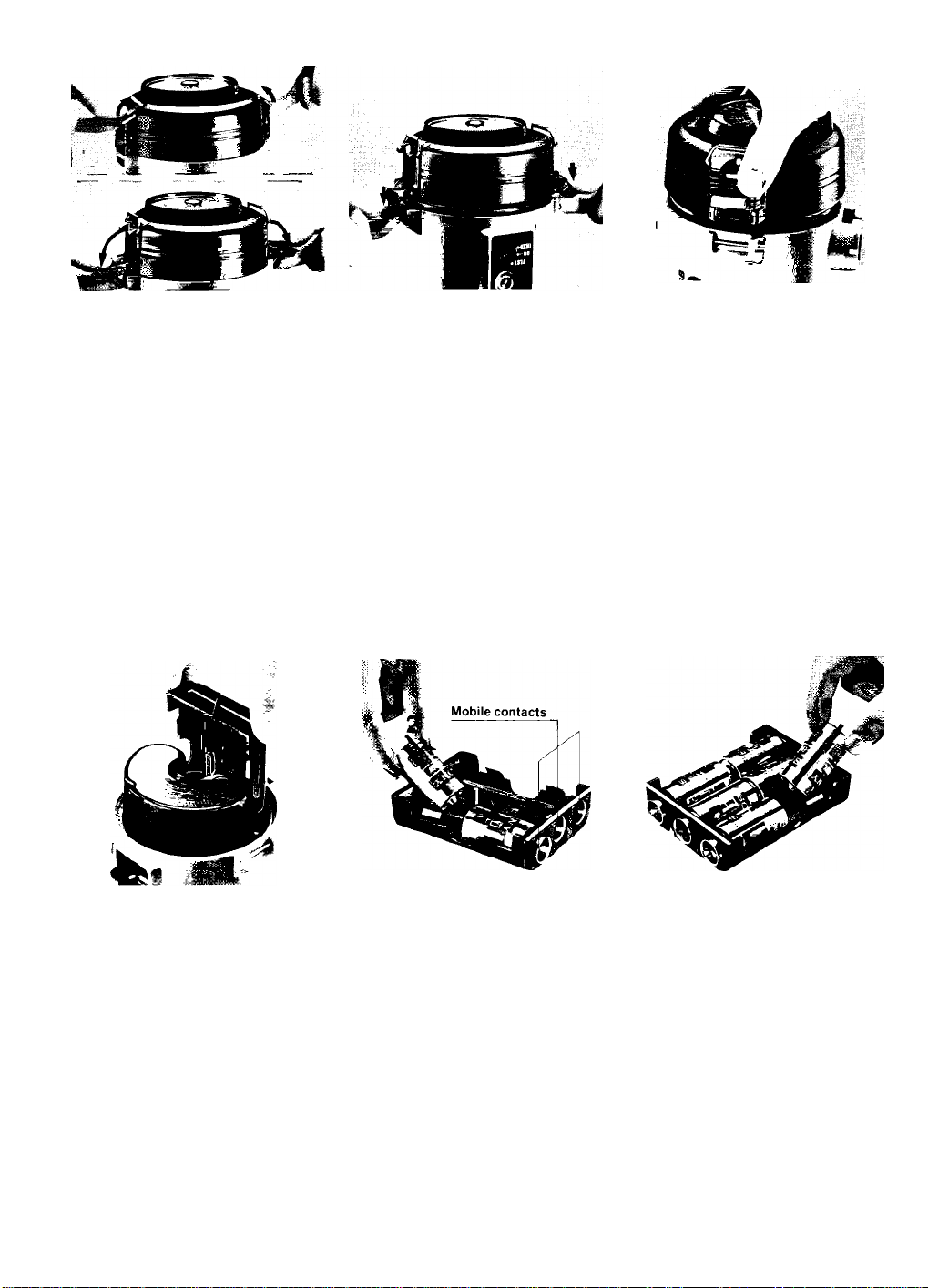
BASIC OPERATIONS
^ Unlock the buckle
" lock/release latches
® and unlock the
buckles ®.
Pull up the buckle lock/release latch
and push the buckles outward and
downward.
Note: The small numbers In circles identify
parts of the speedlight as listed in the
NOMENCLATURE section.
2 Remove the battery
■ chamber cap ®.
Push down on the buckles until the
battery chamber cap is separated
from the speedlight case.
Unlock the silver buckle catches
from the pins on the speedlight
case and pull up on the battery
chamber cap.
•After using the speedlight underwater, rinse
it thoroughly in running water and wipe off
any droplets with a soft cloth before re
moving the battery chamber cap.
Remove the C-type
‘ battery cartridge @
from the battery
chamber.
Install the batteries.
" Install six 1.5V C-type alkalinemanganese batteries or six 1.2 V
NiCd batteries.
Make sure the positive and negative
(-1- and -) terminals are aligned as
shown in the diagram on the car
tridge. Make sure you always push
the first battery in each slot against
the mobile contact.
To remove
Remove the batteries installed in
the side slots first.
• Do not: Insert batteries improperly: leave
flash unit turned on when not in use. Any of
these may damage the flash unit. Also, do
not leave batteries installed when the flash
unit is not being used: it m ay cause the
batteries to explode.
• Do not drop or damage the battery cartridge.
• Use only one brand or type of battery at any
given time. When replacing batteries, re
place alt six at the same time.
•Warning: Batteries may be hot when you
remove them: handle carefully.
• Use of manganese batteries is not recom
mended.
• Check proper battery installation before
shooting. Turn flash unit on and make sure
the SB-102's ready-light lights up within 30
seconds.
• Please see “OPTIMUM BATTERY PER
FORMANCE." page 32.
Page 9
Replace the C-type
■ battery cartridge in
the battery chamber.
Be sure the speedlight power switch
® is in the “OFF” position, then
align the groove on the battery car
tridge with the notch on the inside
of the compartment and slide the
battery cartridge into the chamber.
Replace the battery
" chamber cap.
While holding the buckles away
from the battery chamber cap,
align the battery chamber cap
index @ with the index on the speed-
light case and replace the battery
chamber cap.
Check the 0-ring: Before replacing
the battery chamber cap, examine
its 0-ring for dust and scratches
and be sure it is properly seated
and lubricated.
Lock the buckles.
" Push the battery chamber cap
against the speedlight case so it is
fully seated, hook the silver buckle
catches onto the pins on the speedlight case, and pull the buckles In
ward and upward until they lock
into position,
• When locking the buckles, be sure the silver
buckle catches are hooked onto the pins on
the speedlight case.
A Lock the buckle lock/
■ release latches.
Push the buckle lock/release
latches over the edges of the
buckles to lock them.
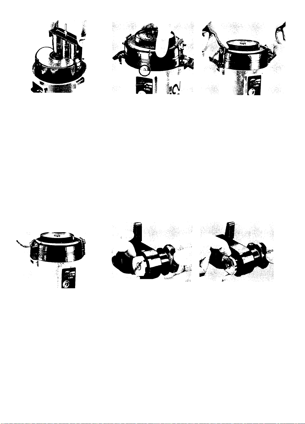
Loosen the joint
" knob ®.
To loosen the joint knob, turn it
counterclockwise while holding the
joint plate (g).
Properly position the
■ joint plate.
Turn the joint knob so the flat sides
of the joint plate are parallel with
the flat edges of the joint.
Page 10
BASIC OPERATIONS —continued.
A4 Insert the joint plate
■ into the joint collar®.
While holding the base of the joint
knob against the joint, slide the joint
plate into the joint collar until it is
fully seated.
• W hen in serting the joint plate into the joint
collar, be sure the flat edges of the joint plate
remain parallel to the flat edges of the joint.
AO Lock the joint.
Align the flash head position
ing index ®) with the "normal” posi
tion mark on the flash head posi
tioning scale, then turn the joint
knob clockwise until the joint is
locked in position.
•See page 18 lor information about removing
the joint.
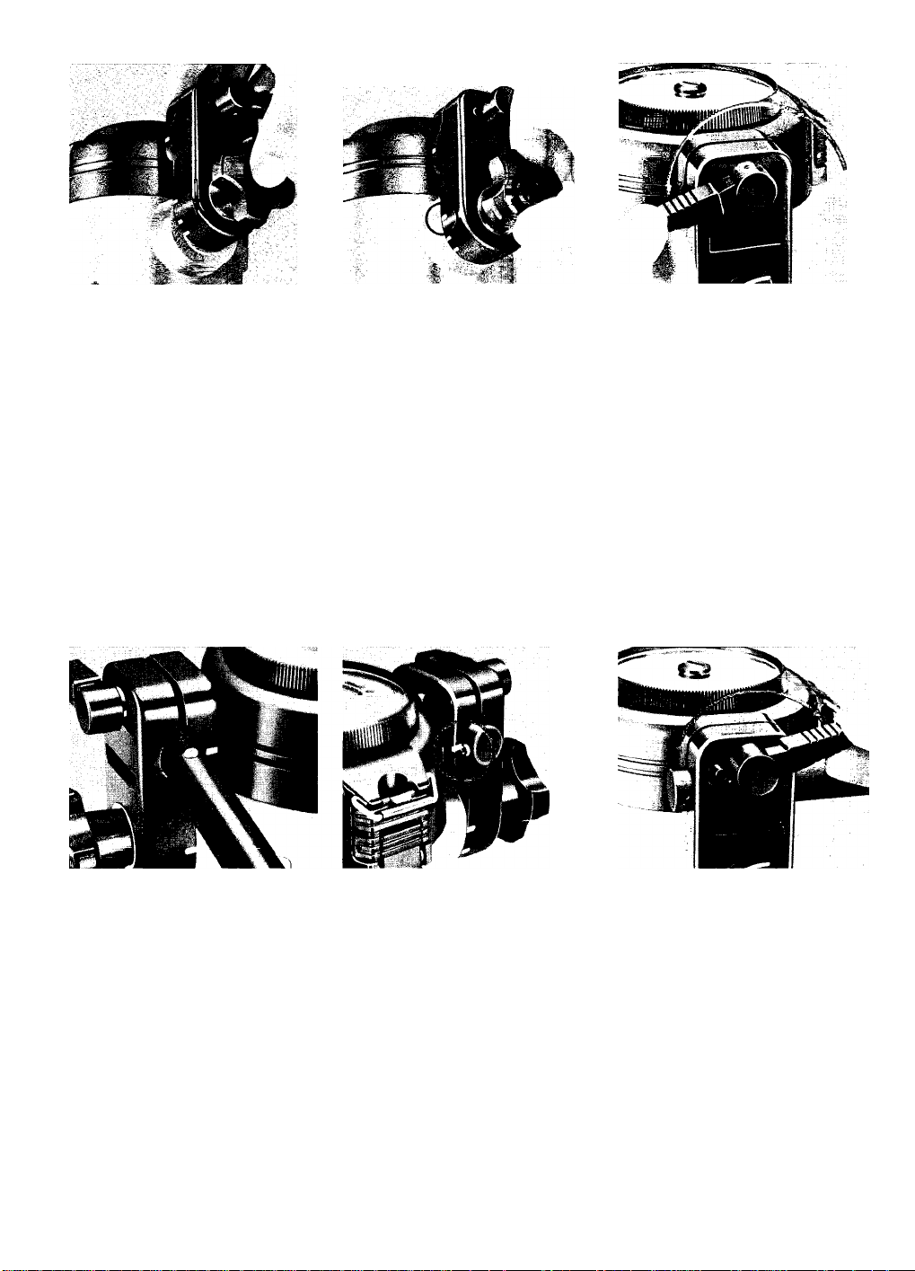
40 Loosen the joint
" lever ®.
Turn the joint lever counterclock
wise as tar as it will go to loosen it.
A A Insert the arm ® into
the joint.
Insert the arm positioning screw @
into the slot in the joint. The arm
can be inserted from either side of
the joint. The normal position is
shown in the photo.
10
4C Position the arm.
Align the arm positioning
screw with the arm positioning
index ® on the joint by turning the
arm 90°.
4 A Lock the arm.
After aligning the arm posi
tioning screw with the arm position
ing index, turn the joint lever clock
wise as tar as it will go to lock the
arm into position.
• Normally, the joint is locked at the top of the
arm.
•Before diving, be sure the joint knob and
joint lever are locked tightly.
Page 11
Loosen the arm
■ knob®.
Turn the arm knob counterclock
wise as far as it will go to loosen it
(the two bracket positioning pins
on the bottom of the grip (g) will
be visible).
Attach the bracket
■ @) to the arm.
Slide the open end of the bracket
between the arm knob and the grip,
seat the two bracket positioning
pins in the two indentations on the
bracket, and turn the arm knob
clockwise as far as it will go to lock
the bracket into position.
• The correct arm/bracket position is with the
three washers on the underside of the
bracket, the rubber side of the bracket facing
up, and flat side of the grip perpendicular
to the bracket.
19. Attach the cord
■ fastening hanger <
to the bracket.
As shown in the photo, slide
cord fastening hanger onto
bracket.
2Q^ Remove the
■ camera’s flash sync
socket cover.
the
Turn the camera’s sync socket
the
cover counterclockwise with a coin
to remove it.
21. Attach the camera
' body to the bracket.
With the camera against the rubber
side of the bracket and the camera’s
tripod socket over the bracket
screw, screw the bracket screw
into the camera’s tripod socket
until the camera and bracket are
securely attached.
Nikonos-V or Nikonos IV-A
11
Page 12

BASIC OPERATIONS —continued.
OO Connect the sync
■ cord® to the
camera.
Remove the dust-proof plastic cap
from the sync cord’s camera plug
(silver). Insert the camera plug in
the camera’s flash socket after
aligning the white index on the flash
sync socket with the red index on
the camera plug. When the camera
plug is inserted, turn its locking ring
clockwise as far as it will go to
secure the plug.
Check the 0-ring; Before con
necting the camera plug to the
camera, examine the plug’s 0-ring
for dust and scratches and be sure
it is properly seated and lubricated.
• Do not apply excessive force to the sync
cord's camera plug, and avoid twisting the
cord as much as possible.
23 Rernove the synchro
■ socket cover (D.
Turn the synchro socket cover
counterclockwise, then pull it up.
24 Connect the sync
cord to the SB-102.
Remove the dust-proof plastic cap
from the sync cord’s speedlight
plug (black). Insert the speedlight
plug into the synchro socket after
aligning the synchro socket index
© with the red index on the speed-
light plug. When the speedlight plug
is inserted, turn its locking ring
clockwise as far as it will go to
secure the plug.
12
Check the 0-ring: Before connect
ing the speedlight plug to the
speedlight, examine the plug’s
0-ring for dust and scratches and
be sure it is properly seated and
lubricated.
• To keep the sync cord out of the way while
shooting, attach it to the hook of the cord
fastening hanger.
25 Confirm the position
■ of thefiash head.
Confirm that the arm positioning
screw is aligned with the arm posi
tioning index, the flash head posi
tioning index is aligned with the
“normal” position mark on the flash
head positioning scale, and the
flash head is facing in the same
direction as the camera's lens. If
the arm positioning screw is not
properly aligned, loosen the joint
lever to reposition it. If the flash
head positioning index is not pro
perly aligned loosen the joint knob
to reposition it.
• See page 18 for information about position
ing the flash head for close-up shooting
within approximately 1m (3.3 ft).
Page 13

26 Set the ASA/ISO film
speed.
Turn the exposure calculation dial
@ until the correct shooting situa
tion mark ® is opposite the ASA/ISO
speed of the film in the camera.
Choose which mark to use accord
ing to the shooting situation:
^ : On-land photography
^ .■ On-land photography with the wide-flash
adapter
: Underwater photography
w* ; Underwater photography with the wide-
flash adapter
ASA/ISO film speed scale
-----------------
32 40 64 80
250
320
In the photograph, the shooting
situation mark (•<: underwater
photography) index is aligned with
ASA/ISO 100.
• For TTL operation with the Nikonos-V
camera, the useable film speed range is
from ASA/ISO 25 to 400.
• The ASA/ISO film speed settings are only for
determining shooting distances and useable
apertures: the exposure calculation dial is
not electrically connected to the flash unit.
• Intermediate ASA/ISO film speed settings
are indicated with dots:
m
500 \ 1000 I
640 1250
AU
m1/i6 •:
mFULL»X^
[HrH**
TaS», ,
SlAVi •!
Tlibht«"^
27. Set the shutter
■ speed on the
camera.
When using the Nikonos-V, set the
shutter speed/mode selector dial
to "A" or any shutter speed setting
from 1/1000 to 1/30sec.; when
using the Nikonos IV-A, set the
shutter speed dial to “A”; in the
case of the Nikonos III, set the
shutter speed dial to 1/60sec.
When using either the NikonoS-Vor
Nikonos IV-A, the proper synchroni
zation speed (1 /90sec.) will be auto
matically set when the SB-102’s
power switch is turned on.
.f/2.8)
• Step 28 is divided into two sections ac
cording to the camera and the shooting mode
in use.
The "A" steps are for TTL automatic opera
tion with the Nikonos-V camera: the "B" steps
are for non-TTL automatic operation with the
Nikonos-V, Nikonos IV-A, or III (the optional
Sensor Unit SU-101 is required for non-TTL
automatic operation).
For information about manual Hash operation,
see pages 25 to 26.
23A. Automatic
'Operation.
A-1. Set the shooting mode
selector switch ® to “TTL.”
A-2. Select an f/stop with the exposure calculation dial.
Select an aperture from the range
of apertures that can be used at the
existing flash-to-subject distance,
tance.
For example, when the shooting
situation mark (^4: underwater
photography) is set at ASA/ISO 100
and the flash-to-subject distance is
1 m (3.3ft), the useable aperture
range is from f/2.8 to f/16.
73
Page 14

BASIC OPERATIONS —continued.
A-3. Set the f/stop on the lens.
When you have determined which
f/stop to use, set this f/stop on the
lens. In the photograph, f/8 is set.
28B. Non-TTL Automatic
' Operation.
B-1. Attach the Sensor Unit
SU-101 to the camera’s acces
sory shoe.
Turn the sensor unit’s locking wheel
counterclockwise as far as it will
go, slip the unit's mounting foot into
the camera’s accessory shoe, and
turn the locking wheel clockwise to
tighten it.
• When a plastic frame finder or optical view
finder is mounted on the camera's accessory
shoe, use the optionai sensor holder to
attach the SU-101 to the speedlight bracket.
B-2. Remove the sensor socket
cover®.
Turn the sensor socket cover
counterclockwise, then pull it up.
14
B-3. Connect the sensor cord to
the SB-102.
Remove the dust-proof plastic cap
from the sensor cord’s speedlight
plug (black). Insert the speedlight
plug into the sensor socket after
aligning the sensor socket index ®
with the red index on the speedlight
plug. When the speedlight plug is
inserted, turn its locking ring clock
wise as far as it will go to secure
the plug.
Check the 0-ring: Before con
necting the speedlight plug to the
speedlight, examine the plug’s
0-ring for dust and scratches and
be sure it is properly seated and
lubricated.
B-4. Set the shooting mode
selector switch to “AUTO.”
Page 15

B-5. Select an f/stop with the exposure calculation dial.
Select an aperture by using the
non-TTL auto shooting aperture
scale # and non-TTL auto shooting
aperture index
For example, when the shooting
situation mark (^: underwater
photography) is set toASA/ISO 100,
the non-TTL auto shooting aperture
index is opposite the f/8 on the
green scale and the f/4 on the pink
one. These then are the useable
f/stops. At f/8, the useable flashto-subject distance range is from
0,6m (2ft) to 2m (6.6ft), At f/4, the
useable flash-to-subject distance
range is from 0.6 m (2ft) to 4 m (13ft).
• The closest shooting distance for non-TTL
automatic operation is 0.6m (2ft) regardless
of the film speed and whether or not the
wide-flash adapter Is being used.
TEST*^
GI»*- ^//'
B-6. Set the selector dial on
the Sensor Unit SU-101.
Set the index on the selector dial to
either the pink circle O or the green
squareO to correspond to the color
of the aperture selected in Step
B-5. For example, if you selected
f/4 in Step B-5, set the index to the
pink circle. If you chose f/8, set the
index to the green square.
B-7. Set the f/stop on the lens.
In the photograph, f/8 is set.
29 Turn on the flash unit.
‘ Turn power switch to “ON."
•As soon as you turn on the SB-102 when
using the Nikonos-V, the shutter speed LED
indicator inside the viewfinder will blink if
the shutter speed/mode selector dial is set
at "A," or at any shutter speed from 1/1000
to 1/30sec. As soon as you turn on the
SB-102 when using the Nikonos IV-A, the
viewfinder LED turns off.
• For normal shooting, the T-S switch should
be in the "OFF" position. For information
about the T-S switch, see pages 29 to 30.
Wait for the readylight® to light.
As soon as the flash ready-light
lights, the SB-102 is ready to fire.
Except for the Nikonos III, if the
camera you are using has a view
finder ready-light, it will light when
the SB-102 is completely recycled.
Note that with the Nikonos-V and
Nikonos IV-A, the exposure meter
must be turned on to activate the
viewfinder ready-light.
15
Page 16

BASIC OPERATIONS —continued.
F
•<
/000 500 250 125 60 30
• With a set of fully recharged NiCd batteries,
the ready-light will light in approximately 5
seconds: with a fresh set of alkalinemanganese batteries, it will light in approxi
mately 14 seconds.
•If either the SB-102’s or the camera's readylight does not light, check that: the batteries
are properly installed, the camera, sensor
unit, and flash unit are securely connected,
and the shutter speed/shooting mode and
ASA/ISO film speed setting on the camera
are correctly set.
•See pages 27 to 28 lor information about
ready-light exposure warning information.
F
J
04 Take the picture.
When the shutter is re
leased, the speedlight fires. After
you take the picture, watch either
the ready-light inside the camera’s
viewfinder or the one on the SB-102.
After a few seconds, it will light
again to indicate the flash unit is
fully recycled and ready for the
next shot.
•If the flash unit fires at its maximum output,
its ready-light will blink lor approximately
2 seconds after the shutter is released to
warn that the shot may have been under
exposed. In this case, recheck the shooting
distance/aperture combination selected
and use the wide-flash adapter or move
closer to the subject, if necessary. This
warning is also indicated by the viewlinder
ready-lights of the Nikonos-V and Nikonos
IV-A.
02 Turn off the flash unit.
between shooting sessions, turn
the power switch on the speedlight
to "OFF.”
16
To conserve battery power
• Turning the power switch off between ses
sions will also help prevent battery leakage.
Page 17

CONTROLS IN DETAIL
Nikonos
Bracket @
As indicated in the diagram there are two positions for
the bracket screw ®; one for Nikonos-V and Nikonos
IV-A and another for the Nikonos III. To reposition the
bracket screw, unscrew it, then screw it back into the
hole or the threaded end of the bracket slot ®. Once
screwed Into the bracket slot, the bracket screw can be
moved to any position.
The larger hole In the center allows the sync cord to be
connected through the bracket to the Nikonos III.
The small hole that goes completely through the bracket
is the sensor holder socket ®. When a plastic frame
finder or optical underwater viewfinder Is mounted on
the camera’s accessory shoe, the optional sensor
holder Is used to attach the Sensor Unit SU-101 to the
speedlight bracket. To attach, align the sensor holder
positioning pin ® on the top 6f the bracket with the hole
Sensor Unit SU-101
attached to the
bracket with the
sensor holder.
in the sensor holder; then screw the knob clockwise
until it is tight.
The small hole on the underside of the bracket is the
tripod socket @.
• When the bracket and arm are attached to the Nikonos IV-A, certain
optical tinder models for older UW-Nikkor 15mm 1/2.8 lenses cannot
be attached. If this presents a problem tor you. authorized Nikon
dealers and service centers can perform the necessary modification.
Arm ®
To attach the arm to the joint @, insert the arm position
ing screw ® into the slot in the joint from either side.
Align the arm positioning screw with the arm positioning
index @ on the joint by turning the arm 90°. After align
ing the arm positioning screw with the arm positioning
index, turn the joint lever (§) clockwise as far as it will go
to lock the arm into position. When the arm is attached
in this manner, the speedlight’s axis will always inter
sect with the lens's optical axis, even if the flash head is
moved up or down on the arm. (Normally, the joint is
locked at the top of the arm.) Before diving, be sure the
joint knob ® and joint lever are locked tightly.
To attach the arm to the bracket, turn the arm knob ®
counterclockwise as far as it will go to loosen it (the two
bracket positioning pins on the bottom of the grip @ will
be visible). Slide the open end of the bracket between
the arm knob and the grip, seat the two bracket posi
tioning pins in the two indentations on the bracket, and
turn the arm knob clockwise as far as it will go to lock
the bracket into position. The correct arm/bracket posi
tion is with the two washers on the underside of the
bracket, the rubber side of the bracket facing up, and
the flat side of the grip perpendicular to the bracket.
17
Page 18

CONTROLS IN DETAIL —continued
Joint
The joint connects the arm to the speedlight and allows
the flash head to be positioned as required for various
shoofing situations.
The arm can be inserted from either side of the joint,
the normal position is shown in the photo. When using
two SB-102 Speedlights and the optional Double Flash
Bracket, insert the arm that is next to the camera’s film
advance lever into the joint from the direction opposite
that shown in the photo. (Flash head positioning scales
are provided on both sides of the joint.)
The joint lever allows the flash head to be turned on the
arm's axis and moved up or down the arm as required.
The joint knob is used to adjust the angle of fhe flash
head (the angle of intersection between the speedlight’s
axis and the lens’s optical axis): The normal angle of the
flash head is with the flash head positioning index ® at
the “normal” positioning mark @ on the flash head posi
Close-Up Shooting in the Non-TTL Automatic Mode
When using the SB-102 in the non-TTL automatic mode
for close-up shooting within approximately 1 m (3.3ft) to
0.3m (1ft), the flash head should be pointed directly at
the subject. Exposure compensation will be necessary,
though, to prevent the subject from being overexposed.
As a rule of thumb, choose an aperture 1/2 to 1 step
smaller (numerically larger f-numbers) than indicated
by the exposure calculation dial. Of course, the exact
amount of exposure compensation depends upon the
shooting situation, so additional compensation may be
required.
To determine the exact amount of exposure compensa
tion required before going to the actual shooting loca
tion, test-shoot in a location with conditions similar to
those of the actual situation (similar water quality, sur
roundings, subjects, and so on). If the conditions
change, the amount of the exposure compensation will
need to be changed correspondingly. Naturally, data
calculated on land will not be applicable to underwater
photography.
To detach
tioning scale. The “normal” position is used for shooting
between 1m (3.3ft) and infinity. For close-up shooting
within approximately 1m (3.3ft), loosen the joint knob,
point the flash head toward the subject, then tighten the
joint knob. In addition to the “normal” position mark on
the flash head positioning scale, "0.6m (2ft)” and “0.3 m
(1ft)” position marks®) ® are provided for use when
shooting subjects at these distances. Flowever, when
the flash head is not in the “normal” position, the joint
must be attached to the top of the arm.
For information about using the target-light to position
the flash head, see page 29.
To detach the joint from the speedlight, turn the joint
knob counterclockwise and slide the joint plate out of
the joint collar while pulling the joint knob.
18
Page 19

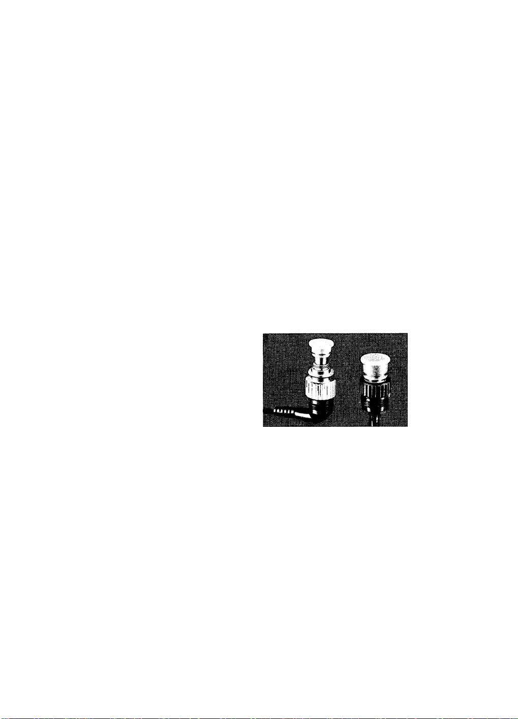
Synchro Socket (D
To connect the sync cord ® to the speedlight, remove
the synchro socket cover (D by turning it counterclock
wise and pulling it up. Remove the dust-proof plastic
cap from the sync cord’s speedlight plug (@ (black).
Insert the speedlight plug into the synchro socket after
aligning the synchro socket index © with the red index
on the speedlight plug. When the speedlight plug is
inserted, turn its locking ring clockwise as far as it will
go to secure the plug.
Never submerge the speedlight in water with the
synchro socket cover removed or get the sync cord
plugs wet. Always make sure either the synchro socket
cover or the sync cord plugs are securely attached
before entering the water.
After shooting underwater, wipe off any water droplets
with a soft cloth before removing the plug to prevent
water from entering the socket. Whenever the sync
cord is not being used or the speedlight is being washed
with the sync cord removed from the synchro socket,
attach the synchro socket cover to protect the socket.
To attach the socket cover press it against the socket to
seat the 0-ring, then turn the locking ring clockwise as
far as it will go.
• To simplify identification, both the tip of the sync cord's speedlight plug
and the inside of the synchro socket are color-coded yellow.
Sensor Socket @
To connect the sensor cord to the speedlight for nonTTL automatic flash control, remove the sensor socket
cover ® by turning it counterclockwise and pulling it up.
Remove the dust-proof plastic cap from the sensor
cord’s speedlight plug (black). Insert the speedlight
plug into the sensor socket after aligning the sensor
socket index @ with the red index on the speedlight
plug. When the speedlight plug is inserted, turn its lock
ing ring clockwise as far as it will go to secure the plug.
Never submerge the speedlight in water with the
sensor socket cover removed or get the sensor cord
piugs wet. Always make sure either the sensor socket
cover or the sensor cord plugs are securely attached
before entering the water.
After shooting underwater, wipe off any water droplets
with a soft cloth before removing the plug to prevent
water from entering the socket. Whenever the sensor
cord is not being used or the speedlight is being washed
with the sensor cord removed from the sensor socket,
attach the sensor socket cover to protect the socket.
To attach the socket cover, press it against the socket to
seat the 0-ring, then turn the locking ring clockwise as
far as it will go.
• To simplifty identification, both the tip of the sensor cord's speedlight
plug and the inside of the sensor socket are color-coded black.
19
Page 20

CONTROLS IN DETAIL —continued.
Sensor UnitSU-101 (Optional)
In combination with the optional Sensor Unit SU-101,
the SB-102 provides non-TTL automatic flash exposure
control. With the SB-102’s shooting mode selector
switch @1 at “AUTO,” the Sensor Unit SU-101 reads the
light reflected back from the subject while the speed-
light is firing and fells the speedlight to turn itself off
when the light output is sufficient for correct exposure.
The selector dial on the back of the SU-101 allows one
of two aperture settings to be selected.
Normally, the SU-101 is attached to the camera’s
accessory shoe. However, when a plastic frame finder
or optical underwater viewfinder is mounted on the
camera’s accessory shoe, the optional sensor holder is
used to attach the Sensor Unit SU-101 to the speedlight
bracket.
Synchronization Speed
The shutter speed at which the SB-102 synchronizes with
a camera depends upon the camera being used. The
table shows the flash sync speeds of various cameras.
Both the Nikonos-V and Nikonos IV-A cameras auto
matically switch to the proper synchronization speed
when the SB-102’s power switch is turned on; when the
switch is turned off, fhe automatic switchover function is
canceled. For convenience, the SB-102 provides infor
mation and warnings through these cameras’ viewfinder
ready-lights.
• Aperture-priority automatic exposure mode ("A") operation on the
Nikonos-V and Nikonos IV-A is canceled when the SB-102 is turned on.
To determine the correct aperture, use the SB-102's exposure calcula
tion dial (see page 22).
Mounting the SU-101 on the camera: Turn the sensor
unit’s locking wheel counterclockwise as far as it will
go, slip the unit’s mounting foot into the camera’s
accessory shoe, and turn the locking wheel clockwise
to tighten it.
Mounting the SU-101 on the bracket: Insert the
sensor holder positioning pin ® on the bracket into the
sensor holder, then screw the sensor holder’s screw
into the sensor holder socket ® on the bracket. To
attach the SU-101 to the sensor holder, follow the same
procedures as when attaching the SU-101 to the
camera’s accessory shoe.
Operating the SU-101: The two-position selector dial
on the back of the sensor unit must be set according to
the instructions in Step B-6 (page 15). To obtain the
correct exposure, position the sensor as close to the
lens as possible.
• For more information about non-TTL automatic operatio n, see page 24.
Camera
Nikonos-V* 1/90 sec, or slower
Nikonos IV-A* 1/90 sec. or slower
Nikonos III
* When batteries in the Nikonos-V or Nikonos IV-A are exhausted, reset the Nikonos-V's shutter speed/mode selector dial to M90 (1/90 sec.) or B
(Bulb), or the Nikonos IV-A's shutter speed dial to M (1/90 sec.) or B (Bulb). TTL automatic flash control is not possible when the Nikonos-V is
in the M90 or B modes.
* This indicates the correct shutter speed as determined by the subject's brightness and the aperture setting. Although this is not a speedlight
function, it is helpful when using daylight fill-in flash shooting.
Sync Speed Camera Setting Operable Shutter Speed Viewfinder Information
A 1/90 sec.
1/60 sec. or slower
1/1000 to 1/125 sec. 1/90 sec.
1/60 to 1/30 sec. as set
M90 or B as set —
A 1 /90 sec.
M (1/90 sec.) or B as set
—
as set
Correct shutter speed blinks**
LED does not light
—
—
20
Remarks
TTL operable
TTL inoperable
Page 21

AUTO ,
«1/16 • и 1/4*; >
«FULL*
ШЕЗ-*
T»S • .А,
Slave • ' ^
T.II6HT* ^
TEST*
ON-*
Eü^eîT
r\\v-
Shooting Mode Selector ®
The shooting mode selector @ has five click-stop set
tings. The shooting modes that can be used with specific
cameras are listed on page 28.
“TTL” position—TTL (through-the-iens) Automatic Fiash Mode
This mode, which can be used only in conjunction with
the Nikonos-V camera, automatically controls the flash
exposure Through-The-Lens (TTL). In this mode, the
Nikonos-V’s SPD (silicon photodiode) reads the light
passing through the lens and automatically signals the
SB-102 to turn itself off when the exposure is correct.
Because the range of useable apertures is larger (from
f/2.8 to f/22 when using ASA/ISO 100 film) than with
non-TTL flash, you can shoot at a variety of flash-to-
subject distances. The farther the subject, the more
light emitted by the flash unit; the closer the subject,
the less light given off. In addition, the TTL mode makes
daylight fill-in fiash and close-up photography easier
than ever.
• The useable film speed range for TTL operation is from ASA/ISO 25 to
400. For information about the apertures that can be used at various
fiim speeds, see page 23.
• TTL operation is not possibie with the Nikonos IV-A or Hi or when the
Nikonos-V’s shutter speed/mode selector dial is set at M90 ( 1/90sec.)
or В (Bulb).
•Even if the Nikonos-V's shutter speed/mode selector dial is set from
1/30 to 1/IOOOsec., TTL operation is not possible when: the sync cord
is not securely connected, the ASA/ISO film speed is set beyond
ASA/ISO 400, or the batteries are completely exhausted.
“AUTO”—Non-TTL Automatic Flash Mode
When the optional Sensor Unit SU-101 is used, this
mode provides non-TTL automatic flash operation. In
this mode, the sensor unit reads the light reflected back
from the subject while the speedlight is firing and tells
the speedlight to turn itself off when the light output is
sufficient for correct exposure. The selector dial on the
back of the SU-101 allows one of two aperture settings
to be selected according to the flash-to-subject distance
and the shooting situation.
• In both the TTL and non-TTL automatic fiash modes, the SB-102 emits
amounts of tight sufficient for subiects having average reflectivity.
Therefore, correct exposure may not be obtainable if the subject's
reflectivity is extremely low or high.
“MFULL”, “M1/4” and “M1/16”-Manual Flash Modes
Manual control is very convenient when the correct
exposure cannot be obtained through non-TTL auto
matic operation. The SB-102 has three manual control
modes for selection according to the flash-to-subject
distance and the shooting situation. The guide numbers
are GN 32 (16) at the “MFULL” position, GN 16 (8) at
“M1/4,” and GN 8 (4) at “M1/16” (when using ASA/ISO
100 film. The guide numbers in parentheses are for
underwater photography). To determine the correct
aperture, use the exposure calculation dial or perform
the calculations yourself (see pages 25 to 26).
21
Page 22

CONTROLS IN DETAIL —continued.
Exposure Calculation Dial
In flash photography, which apertures can be used is
closely related to the flash-to-subject distance. To deter
mine the useable apertures, align the shooting situation
mark on the exposure calculation dial with the ASA/ISO
film speed in use, find the flash-to-subject distance on
the distance scale, then follow the corresponding dis
tance line up to the aperture scale.
The dots on the ASA/ISO film speed scale indicate the
following intermediate settings:
ASA/ISO film speed scale
25 50 100 200 400 800 1600
32 40 64 80
• The exposure calculation dial can be removed to clean sand or other
foreign m atter from behind it.
125 j
160
250 I
320
500 I
640
1000 j
1250
Removing the Exposure Calculation Dial:
Remove the exposure calculation dial screw @ by turn
ing it counterclockwise with a coin, then pull up on the
dial.
To re-attach the dial, correctly align its center notches
with the mounting notches on the back of the flash
head and push down on the dial. Insert the exposure
calculation dial screw and turn it clockwise as far as it
will go.
TTL Automatic Flash Control
In TTL automatic flash photography, the useable aper
tures are from f/2.8 to f/22 (when using ASA/ISO 100
film), although the actual range tor a specific shooting
situation depends upon the flash-to-subject distance.
The actual ranges for specific situations can be easily
determined with the exposure calculation dial.
22
Example 1:
When the shooting situation mark is opposite the
100 on the ASA/ISO film speed scale and you want to
shoot at f/5.6, you can take pictures of subjects located
between 1 m (3.3ft) and 5.6m (I8.4ft).
When the shooting situation mark «m is opposite the
400 on the ASA/ISO film speed scale and you want to
use f/5.6, you can shoot subjects located between 0.7m
(2 3ft)and 4m (13.1 ft).
Before you select an aperture to use, always take the
flash-to-subject distance into consideration. To increase
the flash-to-subject coupling distance as much as pos
sible, select a larger f/stop (a numerically smaller
f-number). In the opposite case, close-up shooting,
select a smaller f/stop (a numerically larger f-number).
Page 23

Example 2:
When shooting a subject underwater at 4m (13ft) with
the wide-flash adapter while usihg ASA/ISO 100 film,
you must use f/2.8.
When several f/stops are useable at a specific flashto-subject distance, make your seiection by taking the
desired depth of fieid and speedlight recycling time into
consideration.
Example 3:
When shooting a subject on iand at 2m (6.6ft) without
the wide-flash adapter while using ASA/ISO 100 film
and you want the largest depth of field possible, select
f/16. If you want to minimize recyciing time as much as
possible, select f/2.8.
In the TTL automatic mode, the SB-102’s useable
ASA/ISO film speed range is from ASA/ISO 25 to 400,
its useable aperture range is from f/2.8 to f/22, and its
fiash-to-subject coupiing distance range is from 0.3m
(1 ft) to 22m (72.2ft). However, the reiationship between
the useabie aperture range and the fiash-to-subject
coupiing distance range varies according to the
ASA/iSO speed of the fiim in use, the type of photo
graphy (on iand or underwater), and whether or not the
wide-fiash adapter is being used.
TTL Auto Shooting Range
On land
400 25
2.8
— — — — 4 to 22 (13 to 72) 3 to 16 (9.8 to 52) 2 to 11 (6.6 to 36)
4
2.8 — — — 3 to 16 (9.8 to 52)
4
5.6
8 5.6 4
11
8 5.6 4 2,8
16 11 8
22 16 11
— 22 16
— —
* These figures should only be used as a guide because flash-to-subject coupling distance ranges are affected by the existing conditions
(water quality, surroundings, subjects, and so on). For best results, test-fire the flash before actually shooting.
_
2.8
2.8
5.6
8 5.6 0.5 to 2.8 (1,6 to 9.2) 0.3 to 2(1 to 6.6) 0.3 to 1.4 (1 to 4.6)
11
22
16
Without adaptor
—
2 to 11 (6.6 to 36)
—
1.4 to 8 (4.6 to 26) 1 to 5.6 (3.3 to 18)
1 to 5.6 (3.3 to 18) 0.7 to 4 (2.3 to 13) 0.5 to 2,8 (1.6 to 9.2) 0.3 to 2 (1 to 6.6)
4
0.7 to 4 (2.3 to 13) 0.5 to 2.8 (1.6 to 9.2)
8 0.3 to 2 (1 to 6.6)
11
0.3 to 1.4(1 to 4.6) 0.3 to 1 (1 to 3.3)
On land
With adaptor
2 to 11 (6.6 to 36) 1.4 to 8 (4,6 to 26) 1 to 5.6 (3.3 to 18)
1.4 to 8 (4.6 to 26) 1 to 5.6 (3.3 to 18) 0.7 to 4 (2.3 to 13)
0.3 to 1.4(1 to 4.6) 0.3 to 1 (1 to 3.3) 0.3 to 0.7 (1 to 2.3)
Underwater*
Without adaptor
0.7 to 4 (2.3 to 13)
0.3 to 2 (1 to 6.6)
0.3 to 0.7 (1 to 2.3) 0.3 to 0.5(1 to 1.6)
Unit: m (ft)
Underwater*
With adaptor
1.4 to 8 (4.6 to 26)
0.5 to 2.8 (1.6 to 9.2)
0.3 to 1.4 (1 to 4.6)
0.3 to 1 (1 to 3.3)
23
Page 24

CONTROLS IN DETAIL —continued.
Non-TTL Automatic Flash Control
When using the optional Sensor Unit SU-101, you can
select one of two useable apertures.
The useable apertures vary according to the ASA/ISO
speed of the film in use, but they can be easily deter
mined with the exposure calculation dial.
When the correct shooting situation mark is aligned
with the correct speed on the ASA/ISO film speed scale,
the non-TTL auto shooting aperture index ® above the
shooting situation mark indicates the useable apertures
(color-coded green and pink) on the non-TTL auto
shooting aperture scale.
To obtain the correct exposure, choose one of the two
useable f/stops and set the index on the sensor unit’s
selector dial to either the pink circle or the green square
to correspond to the color of the aperture selected.
Before doing this remember to take the flash-to-subject
distance into consideration.
• When the shooting situation mark index is aligned with an intermediate
setting on the ASA/ISO film speed scale (for example, ASA/ISO 64).
the non-TTL auto shooting aperture index indicates two useable inter
mediate apertures on the non-TTL auto shooting aperture scate. In this
situation, set one of the two intermediate apertures on the lens.
• In non- TTL automatic operation, the minimum fiash-to-subject coupling
distance is always 0.6m (2ft). The maximum flash-to-subject coupling
distance is determined by your choice of shooting situation marks
regardless of the ASA/ISO speed of the film in use. The coupling ranges
that correspond to the four shooting situation marks are shown in the
chart.
Example:
When shooting underwater«<while using ASA/ISO 100
film, the useable f/stops indicated on the non-TTL auto
shooting aperture scale are f/4 and f/8. Using the aper
ture scale, distance lines, and distance scale, the
flash-to-subject coupling distance ranges are deter
mined to be from 0.6m (2ft) to 4m (13.1ft) for f/4 and
from 0.6m (2ft) to 2m (6.6ft) for f/8. Therefore, when
the subject is beyond 2m (6,6ft), you must select f/4.
When the subject is within 2m (6.6ft), you can choose
either f/4 and f/8. If larger depth of field is desired, use
f/8; if shorter recycling time is preferable, select f/4.
Remember to set the sensor unit’s selector dial to the
same color-coded position as the aperture on the
exposure calculation dial you have selected.
Non-TTL Auto Shooting Range
Shooting
Situation Mark
w
SU-101’s Selector
Dial Setting
0(pink circle)
□ (green square)
0(pink circle)
□ (green square)
0(pink circle)
□ (green square)
w 0(pink circle)
□ green square)
Coupling Distance
0.6 to 8 (2 to 26)
0.6 to 4 (2 to 13)
0.6 to 5.6 (2 to 18)
0.6 to 2.8 (2 to 8.9)
0.6 to 4 (2 to 13)
0.6 to 2 (2 to 6.6)
0.6 to 2.8 (2 to 8.9)
0.6 to 1.4 (2 to 4.3)
Unit: m (ft)
24
Page 25

AUTO ,
«1/16 • .
«1/4
«FUIL*»V ''
mo*
SUVE •/ j
Tuoht« '
OFF
Manual Flash Control
Manual flash operation allows you to control the light
output of the SB-102 by setting the shooting mode
selector to one of three positions: “MFULL,” “M1/4,”
or “M1/16.”
To determine which setting to use, begin by aligning the
correct shooting situation mark with the correct speed
on the ASA/ISO fiim speed scale. Next, locate the
flash-to-subject distance on the distance scale and
follow the corresponding distance line up as it crosses
the aperture scale. At each intersection between the
distance line and an f/stop iine on the aperture scale,
one of four conditions will be present: 1) the distance
line will intersect the extreme right-hand edge of the
f/stop line (the “MFULL” mark), 2) the distance iine will
intersect a semicircle (the “M1/4" mark), 3) the dis
tance line wiil intersect a triangle (the "M1/16” mark),
or 4) the distance line will intersect an unmarked portion
of the f/stop line. The first three conditions indicate the
manuai flash mode that can be used at those particular
f/stops.
Before shooting, set the shooting mode selector to
correct position and set the correct aperture on the lens.
Example 1:
When shooting a subject underwater at 1 m (3.3ft) with
out using the wide-flash adapter while using ASA/ISO
100 film, you can select one of three aperture/mode
settings: f/16 at “MFULL,” f/8 at “M1/4,” or f/4 at
“M1/16.”
If the shooting distance changes to 5m (16.4ft) but you
still want to use “MFULL,” you should use an inter
mediate aperture setting between f/2.8 and f/4.
To determine the correct f/stop without using the expo
sure calculation dial, divide the GN (from the chart on
page 26) by the flash-to-subject distance (in meters).
Example 2:
When shooting a subject underwater at 4 m (13.1ft)
without using the wide-flash adapter while using
ASA/ISO 100 film and “MFULL,” divide the GN (16) by
the shooting distance [4m (13ft)] to get the correct
aperture (f/4).
25
Page 26

CONTROLS IN DETAIL —continued.
Example 3:
Shooting a subject on land at 8m (26.2ft) without using
the wide-flash adapter while using ASA/ISO 100 film
and “MFULL”: The GN for "MFULL” at ASA/ISO 100
on land is 32 (from the chart below). Divide the GN of
32 by the flash-to-subject distance of 8m to get the
correct aperture, f/4. Because water absorbs a great
deal of light, however, you cannot use the same GN
underwater as on land or your shot will be underexposed.
Instead, multiply the on-land GN by 1/2 to 1/3 for under
water photography. (The underwater GNs shown in the
following chart are 1/2 of the corresponding on-land
GNs.)
Guide Numbers in the Manual Mode
Film
speed
(ASA/
ISO)
1600 128(90)
800 90 (64)
400
200 45 (32)
100 32 (22)
50 22(16)
25
• The values in parentheses are when the Wide-Flash Adaptor
SW-102 is being used.
• The full amount of light is emitted when the shooting mode selector
is at "MFULL" and, even if not synchronized, at "AUTO."
On-land shooting
“MFULL” “M1/4”
64 (45) 32 (22) 16(11)
16(11)
“M1/16” “MFULL”
64 (45) 32 (22)
45 (32)
22(16)
16(11) 8 (5.6)
8(5.6) 4 (2.8) 8 (5.6)
22(16) 45 (32)
11 (8) 5.6 (4)
11 (8)
Underwater shooting
64 (45) 32 (22)
32 (22) 16(11)
22 (16)
16(11) 8(5.6)
11 (8)
“M1/4” “M1/16”
16(11)
22(16)
5.6 (4)
4 (2.8) 2(1.4)
11 (8)
11 (8)
8(5.6)
5.6 (4)
4 (2.8)
2.8 (2)
Exposure Compensation
When the Nikonos-V is used with the SB-102 in the TTL
or non-TTL flash mode, exposure compensation is re
quired for over- or underexposing the picture to match
subject or shooting conditions. Each procedure is dif
ferent, so read the following instructions carefully be
fore shooting.
In addition, if you photograph a subject with very high
reflectivity, such as a mirror or metallic surface, under
exposure is almost certain to occur. To prevent this, use
manual flash control.
TTL Exposure Compensation
When using TTL automatic flash control with the
Nikonos-V camera, you can use its ASA/ISO film speed
dial to make an exposure compensation for the shooting
situation or to create intentionally over- or underexposed
photos.
The relationship between the exposure compensation
value and ASA/ISO film speed dial setting is shown in
the following chart:
Exposure Compensation Value
(New ASA/ISO Setting)
ASA/ISO Film
Speed in use
25
50 — 25 50
100 25 50 100 200
200
400 100 200 400
4-2
4-1 0 -1 -2
— — 25 50 100
100 200
400
50 100 200 400 —
— —
The useable aperture range for TTL automatic flash
photography changes according to the exposure com
pensation value being used. Before using the exposure
calculation dial to determine the useable aperture
range, align the correct shooting situation mark with
new (compensation) setting on the ASA/ISO film speed
scale.
For example, to make a -F2 exposure compensation
when using ASA/ISO 100 film, reset the ASA/ISO film
speed scale to ASA/ISO 25, then read the modified
shooting distance from the dial.
•Positive (-F) exposure compensation cannot be made at some film
speeds, and negative (-) exposure compensation cannot be made at
other film speeds. In these cases, make the necessary compensation
in the non-TTL automatic mode (see page 24) or use one of the manual
flash modes.
• When you finish making the exposure compensation, be sure to reset
the ASA/ISO film speed dial on the Nikonos-V and the ASA/ISO film
speed scale on the speedlight.
26
Page 27

Non-TTL Automatic Flash Exposure Compensation
When shooting in the non-TTL automatic flash exposure
mode, exposure compensation can be made by stop
ping down or opening up the lens. To compensate for
a dark subject, use a 1/2- to 2-step smaller aperture
(a numerically larger f-number). To compensate for a
light subject, use a 1/2- to 2-step larger aperture (a
numerically smaller f-number).
• The ready-light will light up when the SB-102 has recycled to 80% of
its full capacity. Therefore, if you want to shoot a subject at either the
minimum or maximum camera-to-subject coupling distance in the
non-TTL automatic mode or one of the manual modes, it is best to wait
until a few seconds after the ready-light has lighted.
•/As the voltage of the batteries decreases with use, the GN of the flash
unit decreases slightly.
• The voltage of NiCd batteries decreases rapidly when their power is
almost exhausted, increasing the recycling time. When this occurs,
stop using them immediately and recharge them or they may be
damaged.
• When using alkaline-manganese batteries, if recycling takes 30
seconds or longer, replace the batteries with a fresh set.
• The ready-light goes out when the flash unit is turned off.
• W hen the exposure meters of the Nikonos-V and Nikonos IV-A are not
activated, the cameras' viewfinder ready-lights will not light even if the
speedlight is turned on (except when the shutter speed/mode selector
dial or shutter speed dial is set at M90 or M). Always confirm that the
viewfinder ready-light is lighted before shooting.
• When the shutter speed/mode selector dial or shutter speed dial of the
Nikonos-Vor Nikonos IV-A is set at M90 or M, the viewfinder ready-light
lights when the flash unit's ready-light lights.
Ready-Light
After its power switch is turned on, the ready-light on
the SB-102 will light to indicate that the SB-102 has re
cycled and is ready to fire. If you are using either a
Nikonos-Vor Nikonos IV-A camera, its viewtinder readylight will also light at the same time to let you know the
flash unit is ready for the next shot.
In addition, the viewfinder ready-lights of the Nikonos-V
and Nikonos IV-A blink to warn of improper settings. If
this happens, check that the camera and flash unit are
securely connected, and the shutter speed/shooting
mode and ASA/ISO film speed on the camera are
correctly set.
Warning Function: Beyond Auto Shooting Range
In the TTL and non-TTL automatic modes, the readylights on the flash unit and in the camera’s viewfinder
blink for approximately 2 seconds if the flash unit has
fired at its maximum output to indicate that the light
output may not have been sufficient for correct expo
sure. If this happens, recheck the flash-to-subject dis
tance. If it is beyond the coupling distance range, use
a larger aperture (a numerically smaller f-number), if
possible, or move closer to the subject.
Because the voltage of batteries (especially alkalinemanganese batteries) decrease rapidly with use, the
GN of the flash unit will decrease slightly. The flash
output of the SB-102 also varies according to the
amount of ambient light and the subject's reflectivity.
27
Page 28

CONTROLS IN DETAIL —continued.
Because of these three factors, the ready-light may
blink to indicate that the light output was insufficient
for correct exposure even if the subject was within the
coupling distance range.
Camera and Speediight Ready-Lights'
Camera Shutter Speed Setting (sec.)
A, 1/1000 to 1/30 TTL Lights Lights or biinks' Does not light
Nikonos-V
Nikonos IV-A
Nikonos iii
1. When the speediight has recycled.
2. When the ASA/ISO film speed dial is set to beyond ASA/ISO 400.
3. In the auto mode, the optional Sensor Unit SU-101 is required.
4. Speeds of 1/500 second, 1/250 second, and 1/125 second cannot be used because the sync shutter speed is 1/90 second or slower.
I 1= Proper flash synchronization is not possible because the shutter speed/shooting mode is improperly set.
• When the camera is set at M90 or M. the camera's exposure meter will not operate even if the shutter release button is depressed.
A, 1/1000 to 1/30 MFULL, M1/4, M1/16, AUTO' Lights Lights
M90(1/90), B
M90 (1/90), B
A TTL
A
M(l/90), B
M (1/90), B
1/500 to 1/30"
1/500 to 1/30"
Shooting mode
TTL Lights
MFULL, M1/4, M1/16, auto' Lights
MFULL, M1/4, M1/16, AUTO' Lights Lights Does not light
TTL Lights — Biinks
MFULL, M1/4, M1/16, AUTO'
TTL
MFULL, M1/4, M1/16, AUTO' Lights
Other Warning Functions:
1. When the shutter speed/mode selector dial of the
Nikonos-V is set to M90 (l/90sec.) or B (Bulb), or
when the shooting mode selector switch of the flash
unit is set to "TTL” when using the Nikonos IV-A.
2. When the sync cord is not securely connected to the
Nikonos-V.
3. When the ASA/ISO film speed setting dial of the
Nikonos-V is set to beyond ASA/ISO 400.
SB-102 ready-light
Lights Biinks Does not light
Lights
Lights — —
Camera ready-light
Meter ON 1 Meter OFF
— Blinks
—
—
— —
Does not light
Lights
Lights
Test Firing
To determine whether or not the flash illumination is
sufficient for a correct exposure, especially when using
the non-TTL automatic mode with distant subjects or
when using bounce-flash photography, test-fire the
flash unit. To test-fire the SB-102, turn its power switch
to “TEST” after the ready-light on thé flash unit lights. If
the ready-light on the flash unit begins blinking after
test-firing, switch to a larger aperture (a numerically
smaller f-number), if possible, or move closer to the
subject before shooting.
This setting also enables you to repeatedly fire the flash
manually with the camera set at B (open-flash firing) to
create multiple-exposure stroboscopic effects or
“paint” the scene with light. When doing this, discon
nect the speediight from the camera or the flash unit
will not fire, even if its power switch is set at “TEST.”
(Remove the sync cord and replace the camera’s flash
28
socket and the flash unit’s sync socket cover before
entering the water.)
•After test firing or open-flash firing, reset the speediight's power switch
to "ON"or "OFF."
In the TTL mode, the shutter must be released to test-fire the flash
unit, but if there is no film in the camera, the ready-light will blink even
if the light output was sufficient for correct exposure.
To avoid this, place a strip of cut film (provided it is not too old) or a
piece of gray paper under the camera's film pressure plate, then
release the shutter.
• Even if two speedlights are connected by the optional Double Sync Cord,
only the speediight tha t is being test-fired will fire.
Page 29

Cord Fastening Hanger
This hanger secures the sync cord to the bracket to
keep it out of the way while shooting.
To use the cord fastening hanger, attach it to the speedlight bracket as shown in the photo, then attach the
sync cord to the hook.
Wide-Flash Adapter SW-102 (D
Designed specifically for use with this flash unit, the
Wide-Flash Adapter SW-102 increases the SB-102’s
angle of coverage from that of a 28mm lens (on land
and underwater) to that of a 15mm lens (underwater).
When the adapter is attached, the SB-102’s GN is re
duced to 22 on land and 11 underwater (when using
ASA/ISO 100 film at “MFULL”),
• When the SW -102 is attached, be sure to use the correct shooting
situation marks {«¡m for underwater or ^ for on-iand shooting) when
setting the exposure calculation dial.
• To prevent overexposure during close-up shooting within approxim ately
0.6m (2ft), attach the adapter even if using a lens other than the
UW-Nikkor 15mm f/2.8N.
• To prevent the loss of the SW-102 and to enable it to be attached
quickly, tie one end of a piece of string to its hole and tie the other end
to the speedlight.
Attaching the SW-102
To attach the adapter, align the adapter’s mounting
notches with the adapter mounting catches on the flash
head, push the adapter onto the flash head as shown in
the photo, then turn the adapter clockwise as far as it
will go.
To remove: Turn the adapter counterclockwise and pull
it off.
Target-Light Function
The SB-102’s target-light enables the flash head to be
accurately positioned for close-up shooting regardless
of whether or not the speedlight is mounted on the
joint/arm. When the speedlight’s power switch is turned
on and the T-S switch ® is turned to "T.LIGFIT” or
“T&S,” the target-light will emit a beam of light to
indicate the direction of the flash head. To accurately
position the flash head, reset it by using the joint and
arm until the beam of light falls on the center of the
subject.
•Although you can shoot while the target-light is on, it is better to turn
the T-S switch to "OFF" or "SLAVE" before shooting to conserve
battery power.
• if the target-light is on when the flash is fired, the target-light will flicker
for a few moments. This does not indicate a malfunction.
• Recycling takes slightly longer when the target-light is being used.
29
Page 30

CONTROLS IN DETAIL —continued.
Replacing the Target-Light
If the target-light burns out, replace it with a new one
(provided) by performing the following procedures:
1. Remove the battery chamber cap (see page 8).
2. Remove the C-type battery cartridge.
3. Turn the target-light holder® counterclockwise ap
proximately 45°.
4. Pull upon the holder.
5. Remove the old lamp and replace it with a new one.
6. Replace the holder and turn it clockwise 45°.
7. Replace the C-type battery cartridge.
8. Replace the battery chamber cap.
• The target-light can also be replaced by an authorized Nikon dealer or
service center if you desire.
When two or more flash units are the same distance
from the subject and face approximately the same
direction, the combined GN of the units can be deter
mined with the following equation:
Combined GN = VGNP-l-GN2^-rGN3'-l-
Where GN 1,2. 3 are the guide numbers of the flash units
• Because the slave flash unit is triggered when the light from the master
flash unit reaches it directly or is reflected to it by the subject, if the
light from the master flash unit does not reach the slave flash unit or if
there are strong light sources nearby, the slave flash unit will not fire.
For best results, test-fire the entire multiple flash sysfem by test firing
the master flash unit before shooting.
•During slave flash photography, avoid other persons using speedlights
or the bursts from their flash units will trigger your sla ve unit.
• The slave flash unit may be triggered by the light from a fluorescent
lamp.
Multiple Flash Photography
The SB-102 has wireless slave flash capability, enabling
it to be triggered by the light fired from another flash
unit.
For multiple flash operation as shown in the diagram,
use either an SB-102 or SB-101 as the master flash unit
(the speedlight connected to the camera). Set the T-S
switch of the slave flash unit (the speedlight
not con
nected to the camera) to "SLAVE” or “T&S.”
After confirming that the flash units’ ready-lights are
lighted, release the shutter to fire the master flash unit.
At the same time, the slave unit will be triggered by the
light fired from the master flash unit.
• There is no limit to the number of SB-102 Speedlights that can be
used as slave flash units at one time.
•For multiple flash operation, all flash units must be in the manual
mode. In the TTL and non-TTL automatic shooting modes, the correct
exposure cannot be obtained because the light from each speedlight
alters the exposure measurement.
Daylight Fill-In Flash Photography
When shooting in daylight, a backlit subject may come
out almost as a silhouette if the background is correctly
exposed. If, on the other hand, exposure compensation
is made to correctly expose the subject, the back
ground may be washed out. To fill in the shadows and
balance the illumination levels of the subject and the
background in daylight shooting, use daylight fill-in flash
photography.
When using the Nikonos-V, its viewfinder LED indicator
will blink to indicate the correct shutter speed under
natural lighting. To obtain the correct exposure with
daylight fill-in flash shooting, turn on the flash unit and
select progressively smaller f/stops (numerically larger
f-numbers) until the camera’s 1/125 second and 1/60
second LEDs begin blinking or until either the 1/60
second or the 1/30 second LED indicator blinks. Make
sure the subject is within the coupling distance range
and, if the viewfinder ready-light is lighted, release the
shutter.
Operable shutter speed (1/90sec.)
r
Adjust the aperture until one
or two of these LED indicators
L
4 lO OO SOO 250 I25 60 30 J
begins blinking.
30
Page 31

TIPS ON SPEEDLIGHT PHOTOGRAPHY.
1. The flash-to-subject coupling distances and use
able apertures indicated by the exposure calcula
tion dial are for dear-water shooting. Therefore,
the correct exposure will be different if the water
is muddy or has floating particles, and some expo
sure compensation must be made.
2. In shallower depths with natural lighting, overex
posure may occur when shooting in the automatic
mode. To prevent this, use the smallest aperture
(the numerically largest f-number) possible or turn
off the speedlight and use only natural lighting.
When shooting with the Nikonos-V, the correct
shutter speed for the lighting conditions is dis
played in the viewfinder. (For more information,
refer to the camera's instruction manual.)
3. When the bracket and arm are attached to the
Nikonos IV-A, certain optical finder models for
older UW-Nikkor 15mm f/2.8 lenses cannot be
attached. It this presents a problem for you,
authorized Nikon dealers and service centers can
perform the necessary modifications.
4. One of the benefits of using a speedlight under
water is that it restores natural colors to subjects
by removing the water’s bluish cast. Occasionally,
though, you may want to include that bluishness
in your photos. Normally, this is rather difficult to
do because the flash unit renders the background
either too light or too dark. To capture the bluish
ness, you must eliminate the difference in light
levels between the subject (illuminated by the
speedlight) and the background (illuminated by
natural light)—a difficult task In the manual flash
mode. The easiest way to balance the light levels
is to use the Nikonos-V and the SB-102 in the
TTL automatic mode and follow the procedures
explained In “Daylight Fill-In Flash Photogra
phy” (page 30).
31
Page 32

OPTIMUM BATTERY PERFORMANCE
1. New batteries
Between manufacture and first use, all batteries
exhibit some drain. Therefore, care should be
taken to purchase the newest (and freshest) ones
possible. To help you do this, some manufacturers
stamp the date of manufacture on the bottom of
each battery. Ask your camera dealer for assist
ance in interpreting the codes.
2. Temperature Battery life ratings are based on operation at around 25°C (77°F). At other temperatures, bat tery life is shortened. Spare batteries should there fore be kept available if operation in low temper atures is anticipated.
3. Continuous use Batteries are drained much more quickly by con tinuous use than by intermittent use.
4. Storage When not in use, the batteries should be removed to prevent leakage which may damage the unit, or even cause combustible gases to be trapped inside the battery chamber. To minimize drain during the period of disuse, store the batteries in a cool, dry place below 20°C (68°F).
5 Battery brands
Do not mix brands of batteries or use batteries
with different model numbers. Also, avoid mixing
new and old batteries since proper performance
will not be obtained and battery leakage may
occur.
6. Disposal Do not dispose of batteries by burning. Also, for
safety’s sake, never disassemble batteries.
7. Polarity When installing batteries, observe the voltage polarities carefully. Reversal of the positive (+ ) and negative (-) terminals will result in leakage. If
leakage should occur, clean the SB-102 carefully
or take it to an authorized Nikon dealer or service
center.
The SB-102 requires an excessive current, so the
life span of the batteries may be shorter than
other speedlights.
8. NiCd batteries
In comparison with regular batteries, NiCd bat
teries provide faster recycling and higher effi
ciency at low temperatures. Flowever, the re
cycling time and the number of flashes per bat
tery set depend upon the age of the batteries,
their charges, and their capacities.
• Do not continue to use NiCd batteries after they are exhausted.
Continued use may reduce their life span or cause leakage.
•Before charging, thoroughly read the battery and battery
charger instructions.
• Charging should only be done for the designated number of
hours on a battery charger recommended by the battery manu
facturer. Excessive charging may cause battery deterioration.
• Charging should only be done in temperatures between S^C
(41 °F) and 35°C(95°F). Never charge batteries while they are
still hot from use.
•Never attempt to charge NiCd batteries that are incorrectly
installed in the battery charger.
•The charging capacity of NiCd batteries may be shortened
after a long period of storage. If this occurs, discharge and
recharge them several times.
•If working time is markedly reduced even after they have been
correctly charged, replace them with a fresh set.
• Do not mix new and old NiCd batteries.
•Do not use NiCd batteries which have been charged for differ
ent iengths of time.
32
Page 33

ACCESSORIES
Numerous accessories are available to increase the
SB-102's versatility.
________
Sensor Unit SU-101
This unit is required w/hen using the SB-102 in the
non-TTL automatic flash mode with the Nikonos-V,
Nikonos IV-A, or Nikonos III.
Sensor Holder (for SB-102)
When a plastic frame finder or an optical underwater
viewfinder is mounted on the camera's accessory
shoe, the sensor holder enables the Sensor Unit
SU-101 to be mounted on the bracket.
Double Flash Bracket
This accessory allows two flash units to be mounted
on the camera at one time, thereby doubling the
amount of flash illumination available. This bracket is
especially useful during close-up shooting because it
enables the subject to be evenly illuminated from the
left- and right-hand sides.
Extension Arm
This accessory increases the length of the arm when
a special lighting effect is desired or needed.
33
Page 34

ACCESSORIES —continued.
Double Sync Cord
When using the Nikonos-V, this cord enabies two
SB-102 Speediights to be used in the TTL automatic
flash mode.
• When using two SB-102 Speediights in the TTL automatic flash
mode, the correct shooting situation mark on the exposure calcula
tion dial must be realigned with a -f-1 higher speed on the ASA/ISO
film speed scale. For example, when using ASA/IS0100 film, align
the correct shooting situation mark with ASA/ISO 200. When you
have finished using the two speediights, realign the scale and
mark.
• If you decide to use only one speedlight in the TTL automatic flash
mode, realign the ASA/ISO film speed scale at its original setting and
turn off the speedlight which Is attached to the gray sync cord. Should
you turn off the speedlight which is attached to the black cord, TTL
automatic flash control is automatically canceled and the unit will fire
at its maximum output regardless of the setting.
•Non-TTL automatic flash exposure is not possible when using two
speediights connected by the optional Double Sync Cord.
Speedlight Case SS-101 (Provided)
Three cushioned compartments inside this styiish tote
bag house the camera and aii parts of the Nikonos
Speedlight Unit SB-102.
Protectors
Special protectors are available to prevent damage to
the SB-102 from inadvertent bumps.
0-rings and lubricant
Additionai 0-rings and iubricant are avaiiabie to aliow
you to maintain the fiash unit in perfect condition.
34
Page 35

SPECIFICATIONS
Flash Type:
Useable Exposure
Modes:
Guide Numbers:
Angle of Coverage:
Batteries:
Number of Flashes/
Recycling Time:
Useable Ranges:
Resistant Pressure:
Target-Light:
Slave Flash Function:
Dimensions:
Weight:
Note: All performance data
[25°C(77°F)1
High-performance silicon
controlled rectifier and series
circuitry
TTL auto exposure (with Nikonos-V
camera); Non-TTL auto exposure
(with optional Sensor Unit
SU-101); and Manual: “MFULL,”
“M1/4," and "M1/16” settings
With ASA/ISO 100 film on land
(underwater), full output: 32 (16):
1/4 output: 16(8); 1/16 output:
8(4)
79° on land; covers picture angle
of 28 mm lens on land and under
water; with Wide-Flash Adapter
SW-102, picture angle increases
to that of a 15mm lens
Six C-type NiCd batteries or six
C-type alkaline-manganese
batteries (high-performance
manganese batteries not
recommended)
NiCd*: 70 flashes/minimum
approx. 5sec.** (depending upon
battery brand and amount of
recharging)
Alkaline-manganese: 120 flashes/
minimum approx. 14sec.**
* Data for C-type NiCd batteries
are applicable only when bat
teries with a 1200mAh capacity
have been recharged by a 120 mA
current for 15 hours at room
temperature.
** More flashes and shorter
recycling times in the TTL,
non-TTL, "M1/4,” and "M1/16”
modes
TTL: ASA/ISO film speed coupling
range: ASA/ISO 25 to 400: useable
aperture range: f/2.8 to f/22 (at
ASA/ISO 100); coupling distance
range: 0.3m (1ft) to 11m (36.1ft)
(at ASA/ISO 100 on land): 0.3m
(1ft) to 5.6m (18.4ft) (at ASA/ISO
100 underwater)
Non-TTL: Useable apertures: f/4
and f/8 (at ASA/ISO 100); coupling
distance range: 0.6m (2ft) to 8m
(26.2ft) (at ASA/ISO 100 and f/4
on land); 0.6m (2ft) to 4m (13.1 ft)
(at ASA/ISO 100 and f/4 under
water): 0.6m (2ft) to 4m (13.1 ft)
(at ASA/ISO 100 and f/8 on land);
0.6m (2ft) to 2m (6.6ft) (at
ASA/ISO 100 and f/8 underwater)
6kg/cm2 (85 Ib/in^) maximum:
useable to depths of 50m (I60ft)
Indicates direction of flash head
when T-S switch is at “T.LIGHT"
or "T&S"
Wireless: triggered by light from
another flash unit when T-S switch
is at "SLAVE” or "T&S"
Flash head: Approx. 139mm(W)x
152.5mm(H)x212mm(D)
Flash head without batteries:
Approx. 1670g
are for normal-temperature operation
Supplied with ten items: Main flash head (including battery
cartridge), joint, bracket (with separate bracket screw), cord fastening
hanger. Wide Flash Adapter SW-102, 0-ring set. target light, sync cord,
arm, and speedlight case SS-101.
Subject to change without notice.
35
Page 36

No reproduction in any form of this manual, in whole
or in part (except for brief quotation in critical articles
or reviews), may be made without written authoriza
tion from the publishers.
NIPPON KOGAKU K.K.
Printed in Japan 8&067-A06
 Loading...