

Page 1
作成承認印 配布許可印
VBA15001-R.3701.A
Printed in Japan Nov 2006
Silver
VBA15101
Black
VBA15001
Copyright© 2006 by NIKON CORPORATION.
All Rights Reserved.
無断転載を禁ず!!
M
サービス
計画課
REPAIR MANUAL
INC
Page 2
VBA15001-R.3701.A
- M ・ -
Specications
Type Single-lens reex digital camera with interchangeable lenses
Eective pixels 6.1 million
CCD 23.7×15.6mm; total pixels: 6.24 million
Image size (pixels) • 3,008 × 2,000 (Large) • 2,256 × 1,496 (Medium) • 1,504 × 1,000 (Small)
Lens mount Nikon F mount with AF coupling and AF contacts
Compatible lenses
*
Type G or D AF Nikkor
AF-S, AF-I All functions supported
Other Type G or D Nikkor All functions supported except autofocus
Micro Nikkor 85mm f/2.8D Can only be used in mode M; all other functions supported except autofocus
Other AF Nikkor†/AI-P Nikkor All functions supported except autofocus and 3D color matrix metering II
Non-CPU Can be used in mode M, but exposure meter does not function; electronic range nder
can be used if maximum aperture is f/5.6 or faster.
*IX Nikkor lenses can not be used †Excluding lenses for F3AF
Picture angle Equivalent in 35-mm format is approximately 1.5 times lens focal length.
Viewnder Fixed eye-level penta-Dach mirror type
Diopter –1.7–+0.5m
-1
Eyepoint 18mm (–1.0 m-1)
Focusing screen Type B BriteView clear matte screen Mark V with superimposed focus brackets
Frame coverage Approximately 95% of lens (vertical and horizontal)
Magnication Approximately 0.8× (50-mm lens at innity; –1.0 m-1)
Reex mirror Quick return
Lens aperture Electronically controlled with instant return
Self-timer Electronically controlled timer with 2, 5, 10 or 20s duration
Focus-area selection Focus area can be selected from 3 focus areas
Lens servo • Autofocus (AF): Instant single-servo AF (AF-S); continuous-servo AF (AF-C); auto AF-
S/AF-C selection (AF-A); predictive focus tracking activated automatically according
to subject status
• Manual focus (M)
Storage
Media SD (Secure Digital) memory cards; camera supports SDHC
File system Compliant with Design Rule for Camera File System (DCF) 2.0 and Digital Print Order
Format (DPOF)
Compression • NEF (RAW): compressed 12-bit • JPEG: JPEG baseline-complaint
Autofocus TTL phase detection by Nikon Multi-CAM 530 autofocus sensor module with AF-assist
illuminator (range approximately 0.5–3.0m/1ft. 8 in.–9 ft. 10in.)
Detection range –1.0–+19EV (ISO 100 at 20°C/68 °F)
AF-area mode Single-area AF, dynamic-area AF, dynamic-area AF with closest subject priority
Focus lock Focus can be locked by pressing the shutter-release button halfway (single-servo AF)
or by pressing the AE-L/AF-L button
ISO sensitivity (Recommended Exposure Index)
200–1600 in steps of 1EV with additional setting one step over 1600
INC
Page 3
VBA15001-R.3701.A
- M ・ -
Exposure
Metering Three-mode through-the-lens (TTL) exposure metering
Matrix 3D color matrix metering II (type G and D lenses); color matrix metering II (other CPU
lenses); metering performed by 420-segment RGB sensor
Center-weighted Weight of 75% given to 8-mm circle in center of frame
Spot Meters 3.5-mm circle (about 2.5% of frame) centered on active focus area
Range (ISO 100 equivalent,
f/1.4 lens, 20°C/68°F)
0–20EV (3D color matrix or center-weighted metering)
2–20EV (spot metering)
Exposure meter coupling CPU coupling
Digital Vari-Program/
exposure modes
Digital Vari-Program ( auto, auto/no ash, portrait, landscape, child,
sports, close-up, night portrait); programmed auto (P) with exible program;
shutter-priority auto (S); aperture-priority auto (A); manual (M)
Exposure compensation –5–+5EV in increments of1/3 EV
Exposure lock Exposure locked at detected value with AE-L/AF-L button
Shutter Combined mechanical and CCD electronic shutter
Speed 30– ¼,000 s in steps of1/3 EV, bulb
White balance Auto (TTL white balance with 420-segment RGB sensor); six manual modes with ne
tuning and preset white balance
Built-in ash • , , , , : Auto ash with auto pop-up
• P, S, A, M: Manual pop-up with button release
Guide number (m/ft) • Approximately 17/55 at ISO 200 and 20 °C/68°F (manual 18/59)
• Approximately 12/39 at ISO 100 and 20 °C/68°F (manual 13/42)
Flash
Sync contact X-contact only; ash synchronization at shutter speeds of up to1/500 s
Flash control
TTL TTL ash control by 420-segment RGB sensor. i-TTL balanced ll-ash for digital SLR
and standard i-TTL ll-ash for digital SLR available when CPU lens is used with built-in
ash, SB-400, SB-800, and SB-600
Auto aperture Available with SB-800 and CPU lens
Non-TTL auto Available with such Speedlights as SB-800, 80DX, 28DX, 28, 27, and 22s
Range-priority manual Available with SB-800
Flash mode • , , , : Auto, auto with red-eye reduction; ll-ash and red-eye reduction
available with optional Speedlight
• : Auto, auto slow sync, auto slow sync with red-eye reduction; slow sync and slow
sync with red-eye reduction available with optional Speedlight
• , : Fill-ash and red-eye reduction available with optional Speedlight
• P, A: Fill ash, rear-curtain with slow sync, slow sync, slow sync with red-eye reduction,
red-eye reduction
• S, M: Fill ash, rear-curtain sync, red-eye reduction
Flash-ready indicator Lights when built-in ash or SB-series Speedlight such as 400, 800, or 600 is fully
charged; blinks for about 3s after ash is red at full output
Accessory shoe Standard ISO hot-shoe contact with sync, signal, and ground contacts and safety lock
Nikon Creative Lighting
System
Supported with built-in ash, SB-400, SB-800, and SB-600; Advanced Wireless Lighting
supported with SB-800 or SU-800 as Commander.
Monitor 2.5in., 230,000-dot, low-temperature polysilicon TFT LCD with brightness adjustment
Video output Can be selected from NTSC and PAL
External interface USB 2.0 Hi-speed
Tripod socket ¼in. (ISO 1222)
Firmware upgrades Firmware can be upgraded by user
INC
Page 4
VBA15001-R.3701.A
- M ・ -
Unless otherwise stated, all gures are for a camera with a fully-charged battery operating at an ambient temperature of 20°C (68°F).
EN-EL9 Rechargeable Li-ion Battery
Supported languages Chinese (Simplied and Traditional), Dutch, English, Finnish, French, German, Italian,
Japanese, Korean, Polish, Portuguese, Russian, Spanish, Swedish
Power source • One rechargeable Nikon EN-EL9 Li-ion battery; charging voltage (MH-23 quick
charger): 7.4V DC
• EH-5 AC adapter (available separately; requires optional EP-5 AC adapter connector)
Dimensions (W ×D×H) Approximately 126×64× 94mm (5.0×2.5 × 3.7in.)
Approximate weight 475g (1lb. 1oz.) without battery, memory card, or body cap
Operating environment
Temperature 0 –+40°C (+32– 104°F)
Humidity Less than 85% (no condensation)
Type Rechargeable lithium-ion battery
Rated capacity 7.4V/1000 mAh
Dimensions (W ×D×H) Approximately 36×56× 14mm (1.4×2.2 ×0.6in.)
Approximate weight 51g (1.8oz.), excluding power cable
INC
Page 5
- D ・ -
VBA15001-R.3701.A
Points to notice for Disassembly / Assembly
㧍
内部に高電圧部あり。カバーを外す 時は感電に注意すること。
カバーを外した後は、修理指針の指 示に従ってメインコンデン
サーの放電を必ず行うこと。
警告
Caution:
Whenever "Separation of Front and rear bodies", "Disassembly of CCD/FPC unit", or
"Disassembly of Bayonet" are performed, be sure to perform "RESET AF-DEFOCUS
COMPENSATION" of camera adjustment software after reassembling.
WARNING
Due to an internal high voltage area,
take extra care not to get
an electric shock when detaching covers.
After removing covers, be sure to discharge the main
condenser according to the instructions of repair manuals
.
Note:
①
When disassembling/(re)assembling, be sure to use the conductive mat (J5033) and wrist strap (J5033-5)
for static protection of electrical parts.
②
Before disassembling, be sure to remove batteries or AC power wires.
③
When disassembling, make sure to memorize the processing state of wires and FPC, screws to be xed
and their types, etc.
④ Because the low pass lter of the imaging CCD PCB is easily damaged, handle it with enough care.
⑤
is indicated in this manual when NK screw is used. Usually the same "NK" screw can be used
approx. up to three times.
(NK screw = Loose-proong screw to which the adhesive is already applied and rmly xed when
screwed in.)
Points to notice for Lead-free solder products
・ Lead-free solder is used for this product.
・ For soldering work, the special solder and soldering iron are required.
・ Do NOT mix up lead-free solder with traditional solder.
・ Use the special soldering iron respectively for lead-free solder and lead solder.
They cannot be used in common.
Changed page
△×
M
サービス
計画課
Feb.05.2007
△
(Addition)
NK
INC
Page 6
- D 2 ・ -
VBA15001-R.3701.A
・
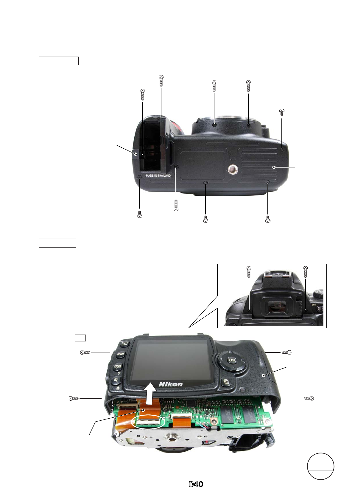
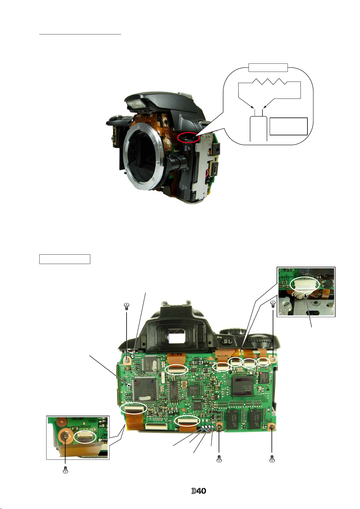
Take out the four screws (#5690) and two screws (#5618).
・
Remove the rear cover.
・
Take out the four screws (#5735)
and ve screws (#5674).
・
Open the power-wire lid.Open the power-wire lid.
・
Remove the bottom cover.
#5735
#5674×2
#5735
#5674
#5674
#5735×2
#5674
・
Remove the rear FPC from the connector.
Rear FPC
#5690×4
Rear cover
#5618×2
Power-wire lid
Disassembly
1. Separation of Front and Rear Bodies
Bottom Cover
Bottom cover
Rear cover
Note: Remove the rear cover slowly so as not to cut rear FPC of
the upper portion of the cover.
△
(Addition)
NK
Changed page
△×
M
サービス
計画課
Feb.05.2007
INC
Page 7
- D ・ -
VBA15001-R.3701.A
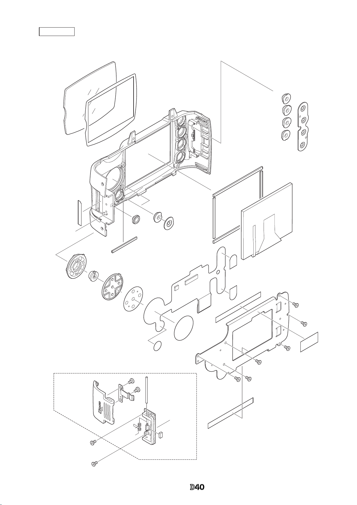
Rear cover
A
A
#402-3
#403
#5401-7
#5424-4
#5425-3
#5426-3
#5427-3
#421-2
#405×2
#1037
#5429-2
#423-2
#408
#5412-1
#5418-5
#413-1
#414
#1016-3
#453
#452
#451×2
#406-3
#750
#670×3
#630×3
#5431-1
#433
#5432-1
#404×2
#448
#407-2×2
#B5431
#5681×2
#753
INC
Page 8
- D ・ -
VBA15001-R.3701.A
#5610×2
#5610×2
#5074
#29-2
#26-2
#131
#626
#5120
#670
#B5024
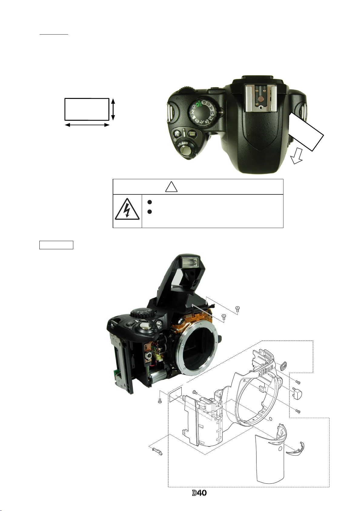
・
Take out the four screws (#5610) and
the screw (#626).
・
Remove the front cover unit (#B5024)
and [#131].
SB pop-up
・
Cut the tracing lm sheet, etc into the below size of piece.
Then insert it into the clearance of the top cover pop-up
part as shown right, and raise the SB by sliding the sheet in
the direction of the arrow.
Approx.2cm
Approx. 4cm
㧍
内部に高電 圧部 あり 。カ バーを外す時は感電に注意す るこ と。
カバーを外 した 後は 、修 理指針の指示に従ってメイン コン デン
サーの放電 を必 ず行 うこ と。
警告
WARNING
Due to an internal high voltage area, take extra care not to get an
electric shock when detaching covers.
After removing the covers, be sure to discharge the main
condenser according to the instructions of repar manuals.
Covers
#750
#792C
INC
Page 9
- D ・ -
VBA15001-R.3701.A
Main
condenser
2KΩ/5W
Be careful so that the top cover does NOT touch the
discharge tool.
Discharge of Main condenser
・
Discharge the main condenser from its both ends.
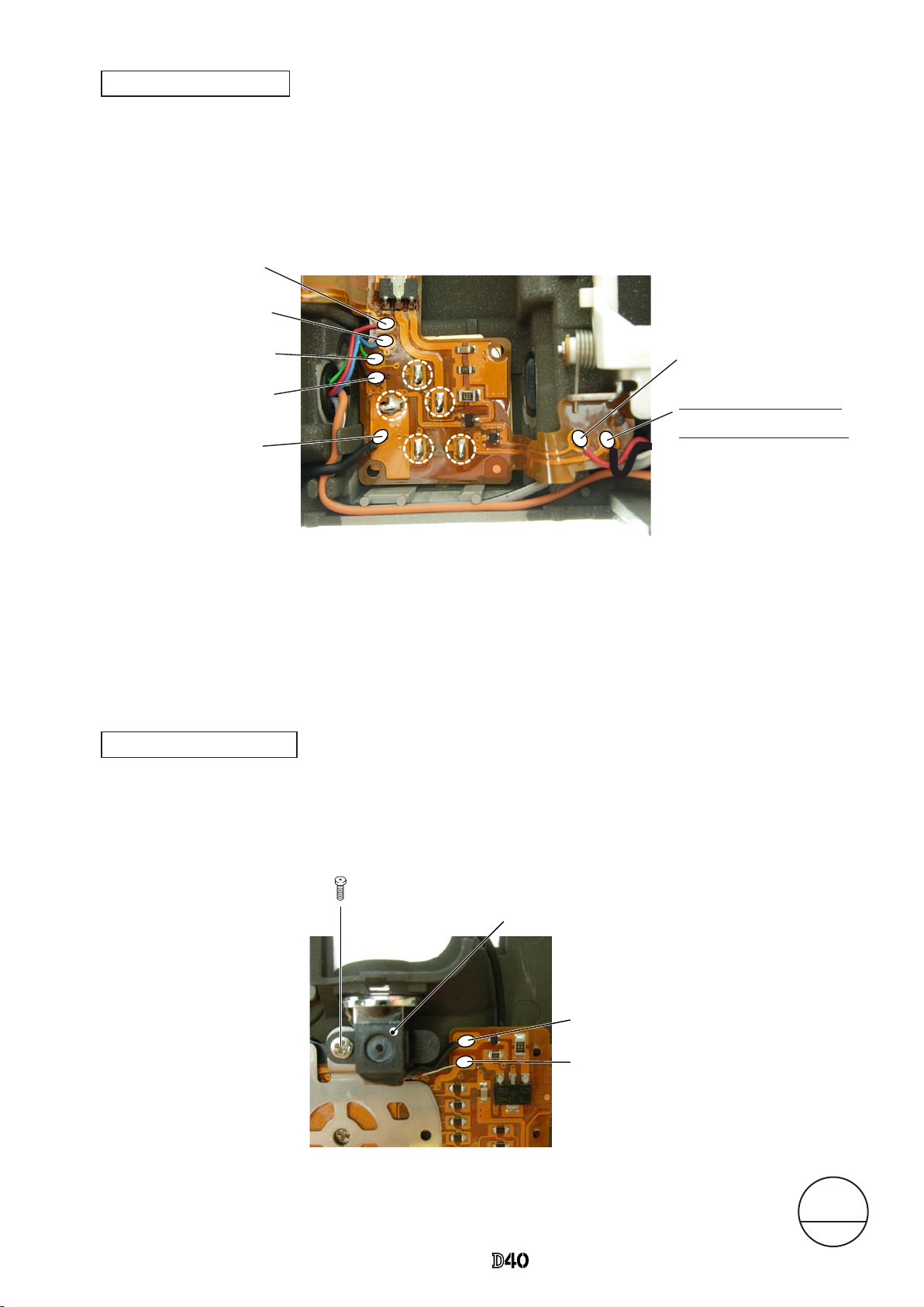
TOGO PCB (#B2001-1)
TOGO PCB unit
Gray
Red
Blue
Gray
Pink: Relay PCB
・
Disconnect the eight FPCs from the connector.
・
Unsolder the ve wires.
・
Take out the ve screws
(
#663).
・
Remove the harness.
・
Remove the TOGO PCB
(
#B2001-1).
#663×5
Harness
TOGO PCB unit: Back
INC
Page 10
- D ・ -
VBA15001-R.3701.A
・
Take out the three screws (#631), and remove the CCD unit (#B3051-1).
CCD unit
Caution:
Some bodies have already washer(s) attached on
the mounting surface of CCD unit.
・
Unsolder the four wires (connected
from Top cover).
Orange: Top cover
White: Top cover
Gray: Top cover
Black: Top cover
SB PCB
#B3051-1
#631×3
INC
Page 11
- D 7 ・ -
VBA15001-R.3701.A
・
Unsolder the wire (connected from Top cover).
Black: Top cover
Top cover
・
Take out the two screws (#5737).
・
Take out the two screws (#635).
・
The top cover and rubber eyecap (#B271)
come off.
DC/DC PCB unit
#5737×2
#B271
#635×2
#797×2
info
AUT
O
#796A
~
D×n
Changed page
△×
M
サービス
計画課
Feb.05.2007
△
(Revision)0~n
INC
Page 12
- D ・ -
VBA15001-R.3701.A
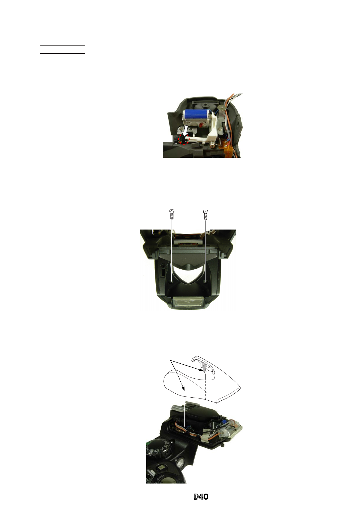
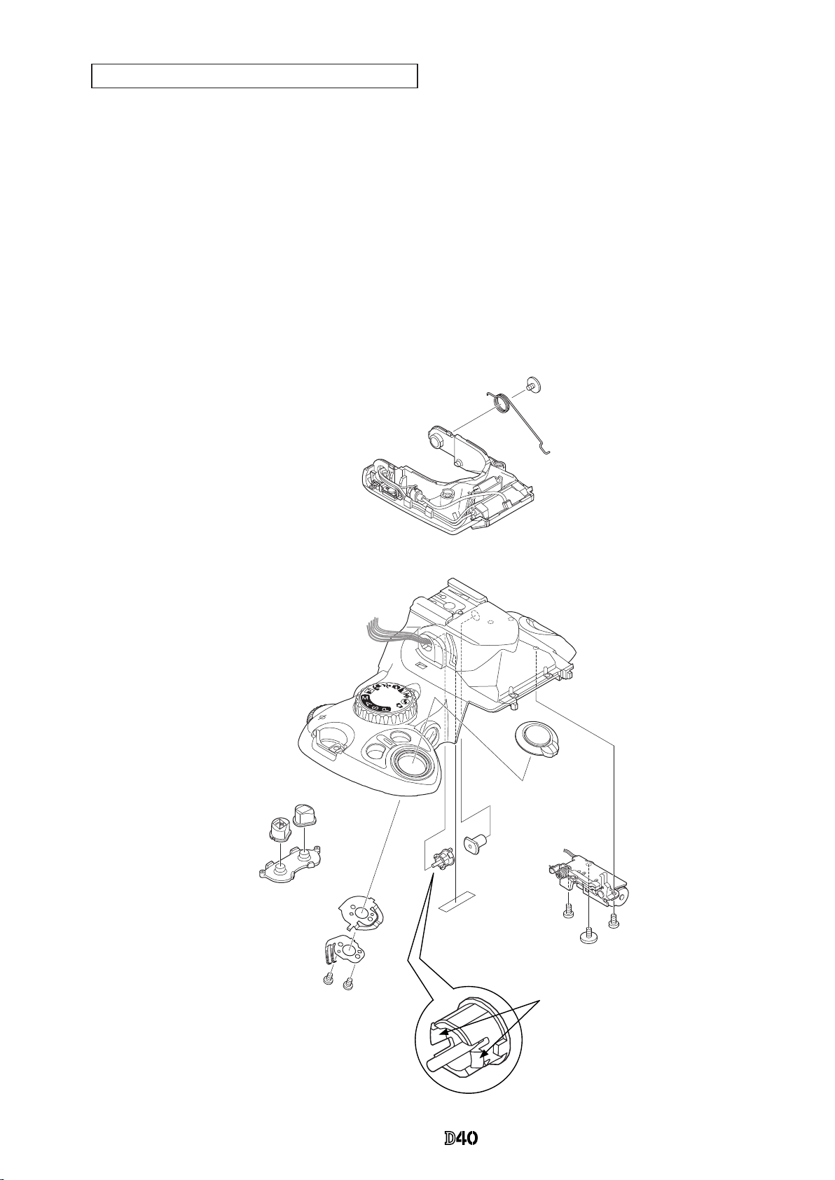
・
Press "Pop-up lever A part" of the top cover unit so that the built-in SB is raised.
・
Take out two screws (#632).
・
Release the two claws. House the built-in SB and remove the SB upper case (#5301).
#632×2
Pop-up lever A part
SB upper case (#5301)
Claw
Disassembly of Top cover
SB upper case
INC
Page 13
- D ・ -
VBA15001-R.3701.A
・
Unsolder the seven wires (connected from SB lower case unit and SB release base unit).
・
Remove the ve solder bridges.
・
Remove the two wires (black and uncoated) (connected from AF-assist illuminator unit).
・
Take out the screw (#608), and remove the AF-assist illuminator unit (#B325-1).
AF-assist illuminator unit (#B325-1)
Black: AF-assist illuminator unit:
Uncoated wire: AF-assist illuminator unit
#608
Top cover FPC / Wiring
AF-assist illuminator unit
Red: SB release base unit
Blue: SB release base unit
Red: SB lower case unit
Blue: SB lower case unit
Green: SB lower case unit
Black: SB lower case unit
Black: DC/DC PCB
△ (
Revision)
Black: SB release base unit
Changed page
△×
M
サービス
計画課
Feb.05.2007
INC
Page 14
- D 0 ・ -
VBA15001-R.3701.A
・
Remove the rubber SW (#382-2), ± Aperture button (#5381), and INFO button (#5383-1).
・
Take out the two screws (#605), and remove [#348], [#347-1] and the release button unit (#B5350).
・
Take out the screw (#650), and release the wire from the boss.
・
Remove [#308-1], while releasing the two hooks.
・
While pressing the SB case rotating shaft (#306-1), take out the screw (#733) and remove the SB-up spring
(#305-1).
・
While watching the wires, remove the SB lower case unit (#B2302).
・
Take out the two screws (#607), and remove the SB release base unit (#B2455).
SB lower case unit / SB release base unit / Buttons
AUT
O
info
#733
#305-1
#B2302
#B5350
#306-1
#308-1
#956
#B2455
#607×2
#650
#347-1
#348
#605×2
#5383-1
#5381
#382-2
Hook × 2
INC
Page 15
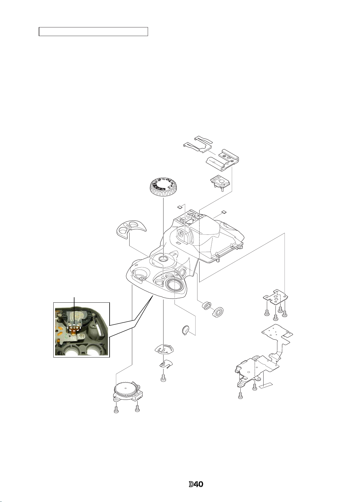
- D ・ -
VBA15001-R.3701.A
AUT
O
#635×2
#B367
#373
#372
#640
#326
#5386-1
#387-2
#B2007-1
#635×2
#956
#654×4
#322
#318-1
#316
#B317
#311-1×2
#B5375
#27-2
・
Remove the three solder bridges.
・
Take out the two screws (#635) and remove the top cover FPC unit (#B2007-1).
・
Remove the AF/AE lock button (#5386-1) and [#387-2].
・
Take out the two screws (#635), and remove the C/D unit (#B367).
・
Take out the screw (#640), and remove [#372], [#373], and mode dial unit (#B5375).
・
Take out the four screws (#654), remove [#322], [#318-1], shoe base (#316) and [#B317].
Top cover FPC unit / other small parts
Solder bridge ×3
INC
Page 16
- D ・ -
VBA15001-R.3701.A
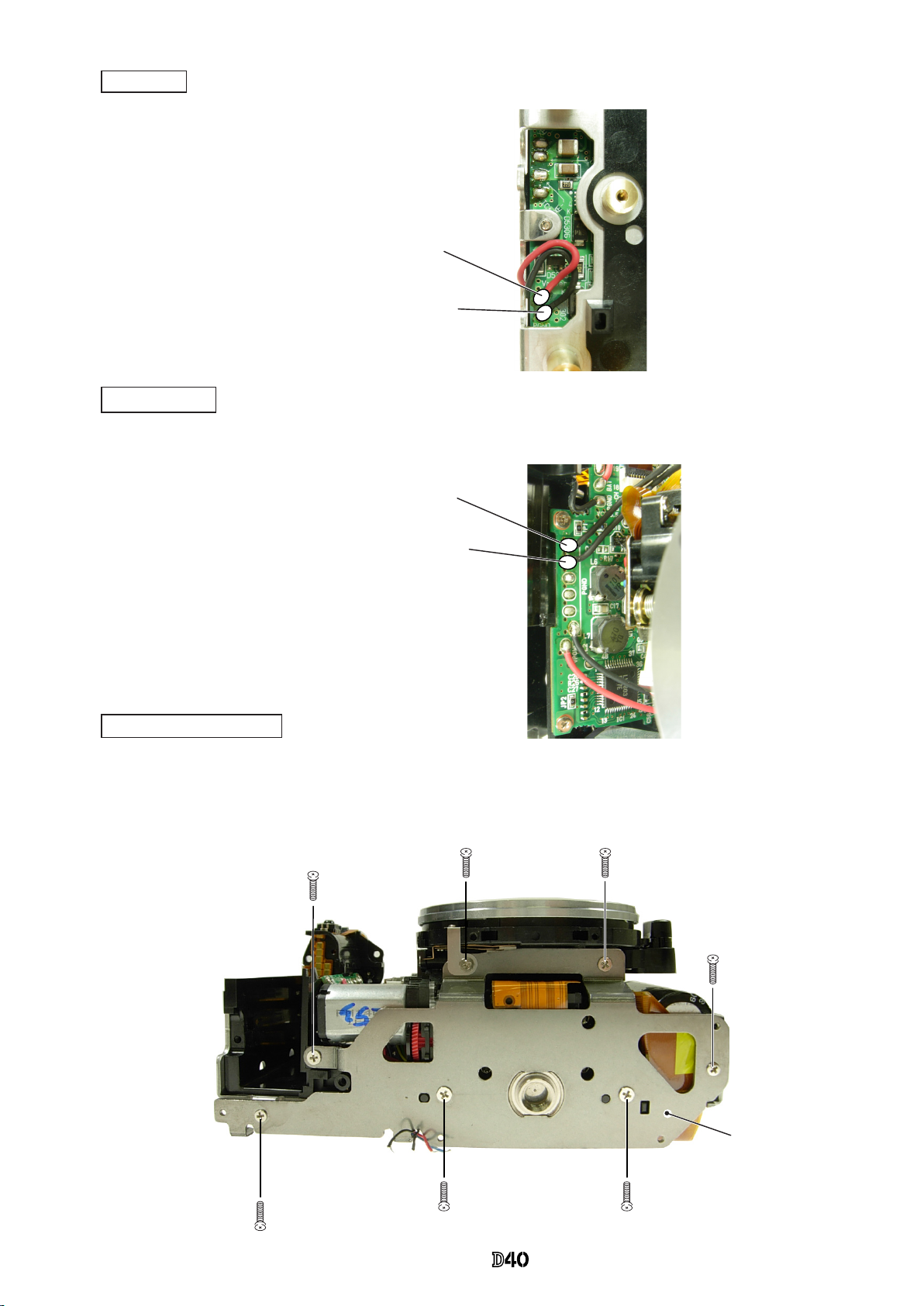
Red: Relay-PCB
Black: Relay-PCB
・
Unsolder the two wires (connected from Relay-PCB).
Bottom base plate unit
・
Take out the ve screws (#616).
・
Take out the two screws (#691).
・
Remove the bottom base plate unit (#B66-2).
Black: Mount GND plate
Black: Front body FPC
SB PCB
DC/DC PCB
・
Unsolder the two wires (connected from Mount GND plate and Frront body FPC).
#616×5
#691
Bottom base
plate unit
(#B66-2)
#691
INC
Page 17
- D ・ -
VBA15001-R.3701.A
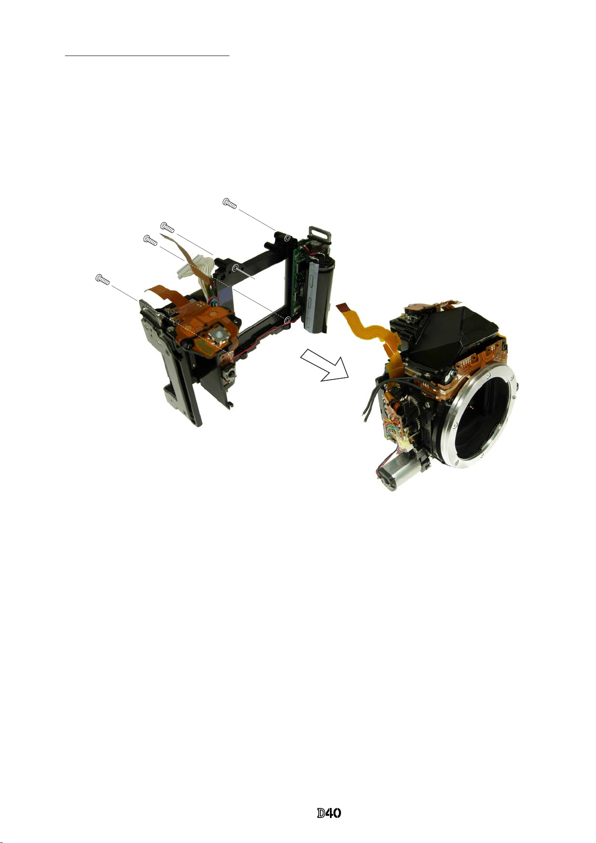
・
Take out the four screws (#624).
・
Separate the front body from the rear body.
Caution: Separate them slowly so as NOT to cut the two wires of the relay-PCB that pass through between the
SB PCB and main condenser.
Separation of Front and Rear bodies
#624×4
INC
Page 18

- D ・ -
VBA15001-R.3701.A
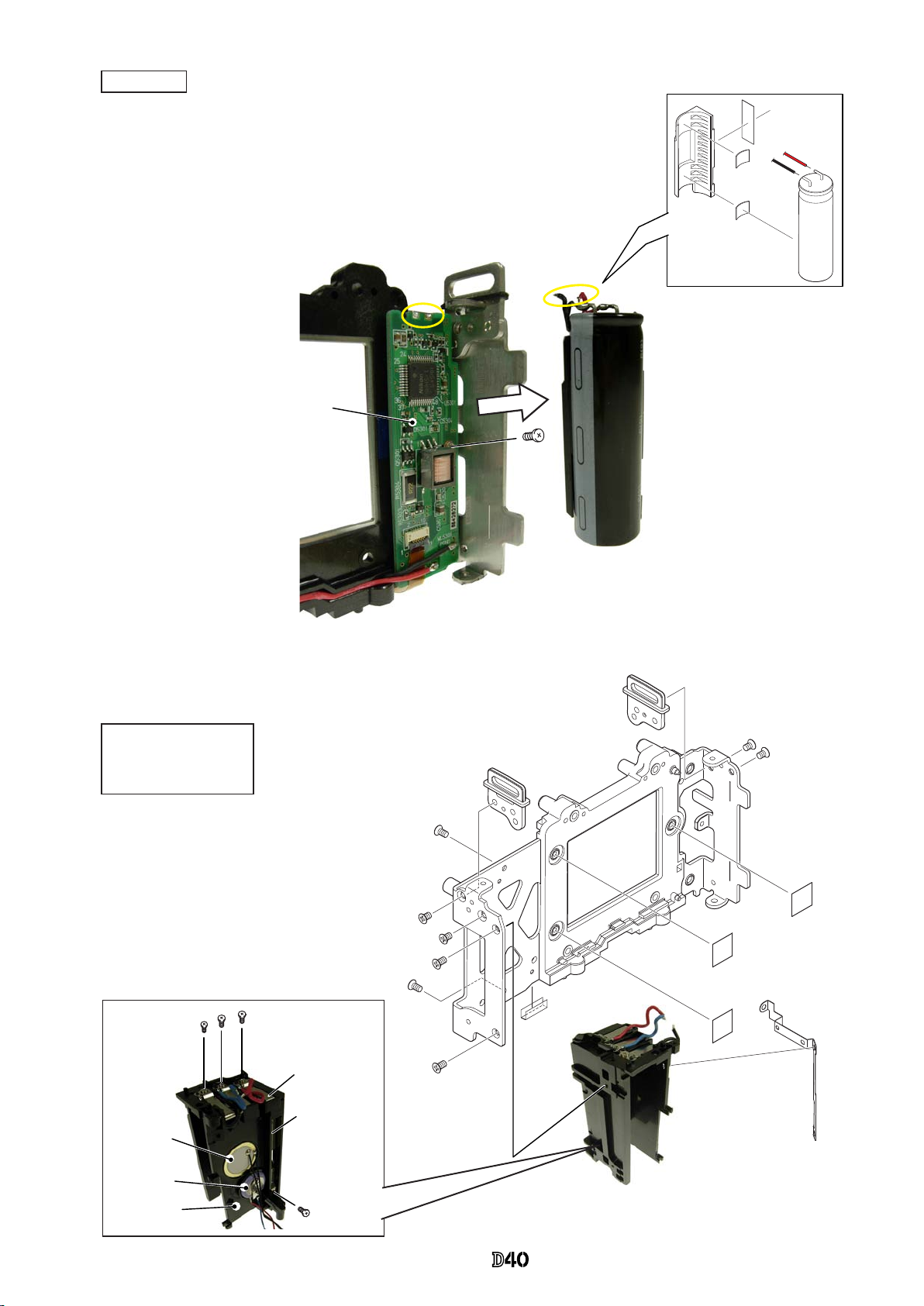
Remote block
・
Remove the ve wires (connected from SB-PCB and Battery box) .
・
Take out the two screws (#670).
・
Remove the DC/DC PCB.
Black:SB PCB
Red:SB PCB
Blue: Battery box
Red: Battery box
Black: Battery box
#670×2
DC/DC PCB
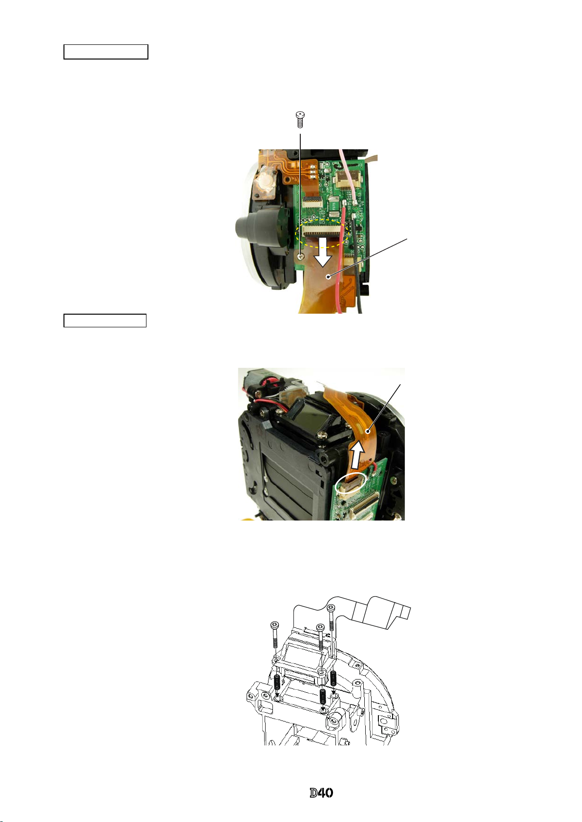
・
Remove SW-FPC [#B2006].
・
Take the two screws (#683).
・
Remove the remote block (#158-1).
2. Rear body
DC/DC PCB
#683×2
#158-1
#B2006
#354
INC
Page 19
- D ・ -
VBA15001-R.3701.A
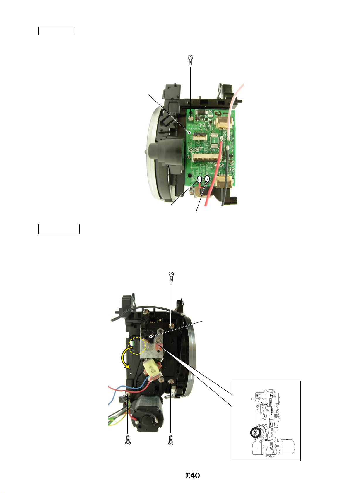
・
Remove the two wires (yellow-circled) of the main condenser.
・
Remove the main condenser that is attached on with the adhesive double-
coated tape.
・
Take out the screw (#687).
・
Remove the SB PCB.
DC/DC lug plate
Eyelet ring unit
Other small parts
#687
Main condenser
#1043-3
SB PCB
Main condenser
#142
#141×2
#1043-3
#1076
#1077
SB PCB
Battery box
#607×3
#157×3
DC/DC
lug plate
#607
Buzzer unit
Backup battery
Battery box
#694×2
#694×2
#143×3
#615×4
#B145×2
#159-1
TA-0005
(7×15)
INC
Page 20
- D ・ -
VBA15001-R.3701.A
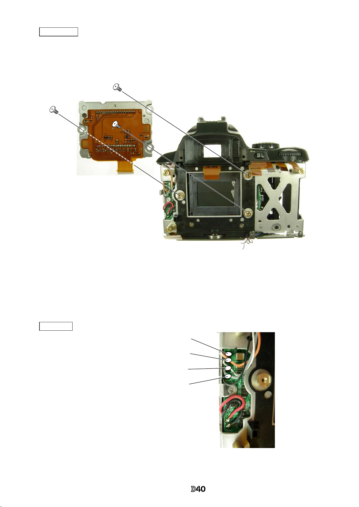
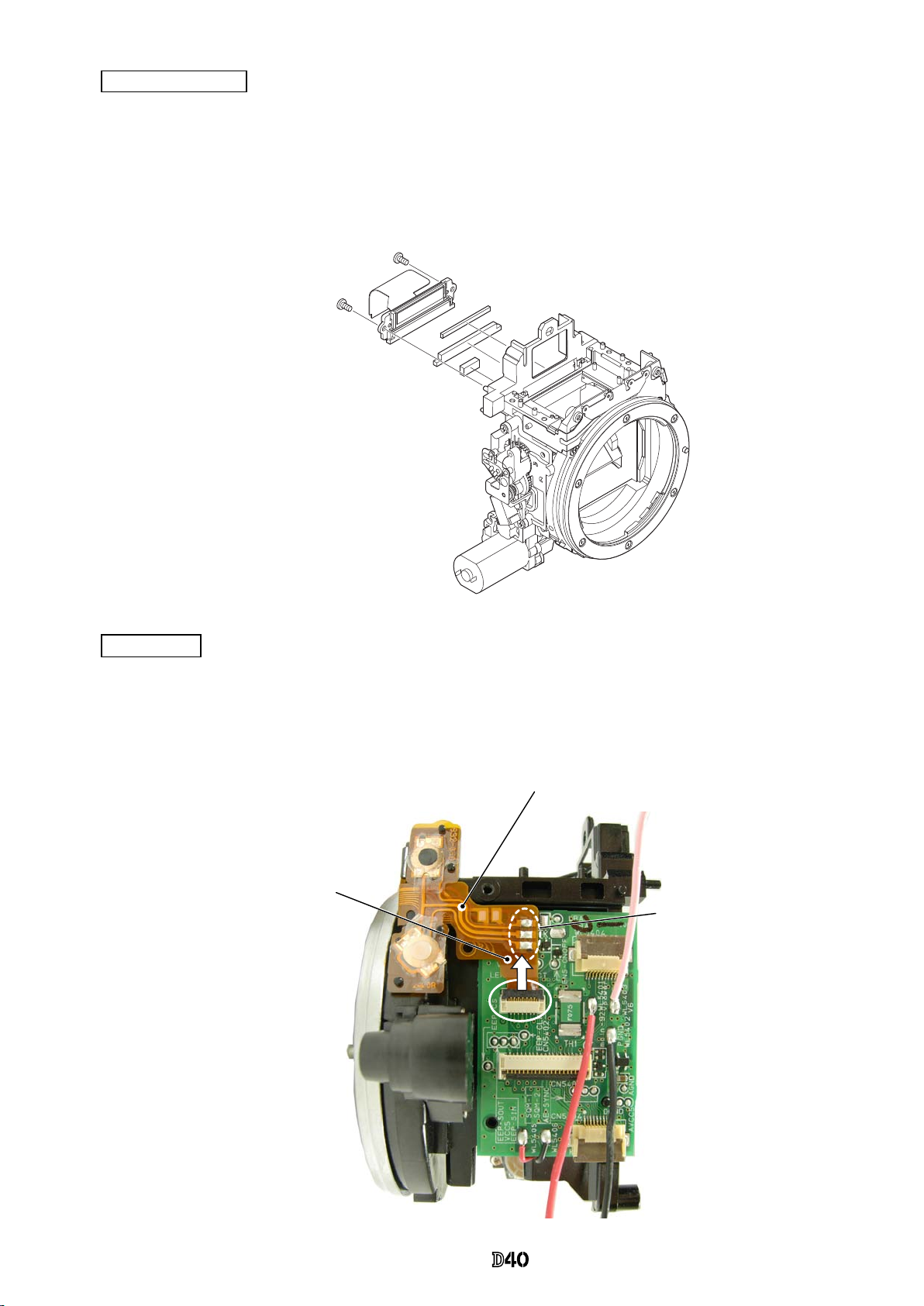
・
Take out the screw (#607), and remove the AE FPC retainer plate (#293).
・
Remove the FPC of the AE FPC unit (#B2008) from the connector.
・
Take out the screw (#604), and remove the AE sensor plate spring (#285-3).
・
Take out the screw (#291-1), and remove [#B2008] and [#290].
・
Take out the two screws (#638), and remove the eyepiece barrel unit (#B261).
Eyepiece barrel unit
AE FPC unit
3. Front Body
#604
#638×2
#290
#291-1
#B2008
#293
#607
#B2008
#B261
#285-3
INC
Page 21
- D ・ -
VBA15001-R.3701.A
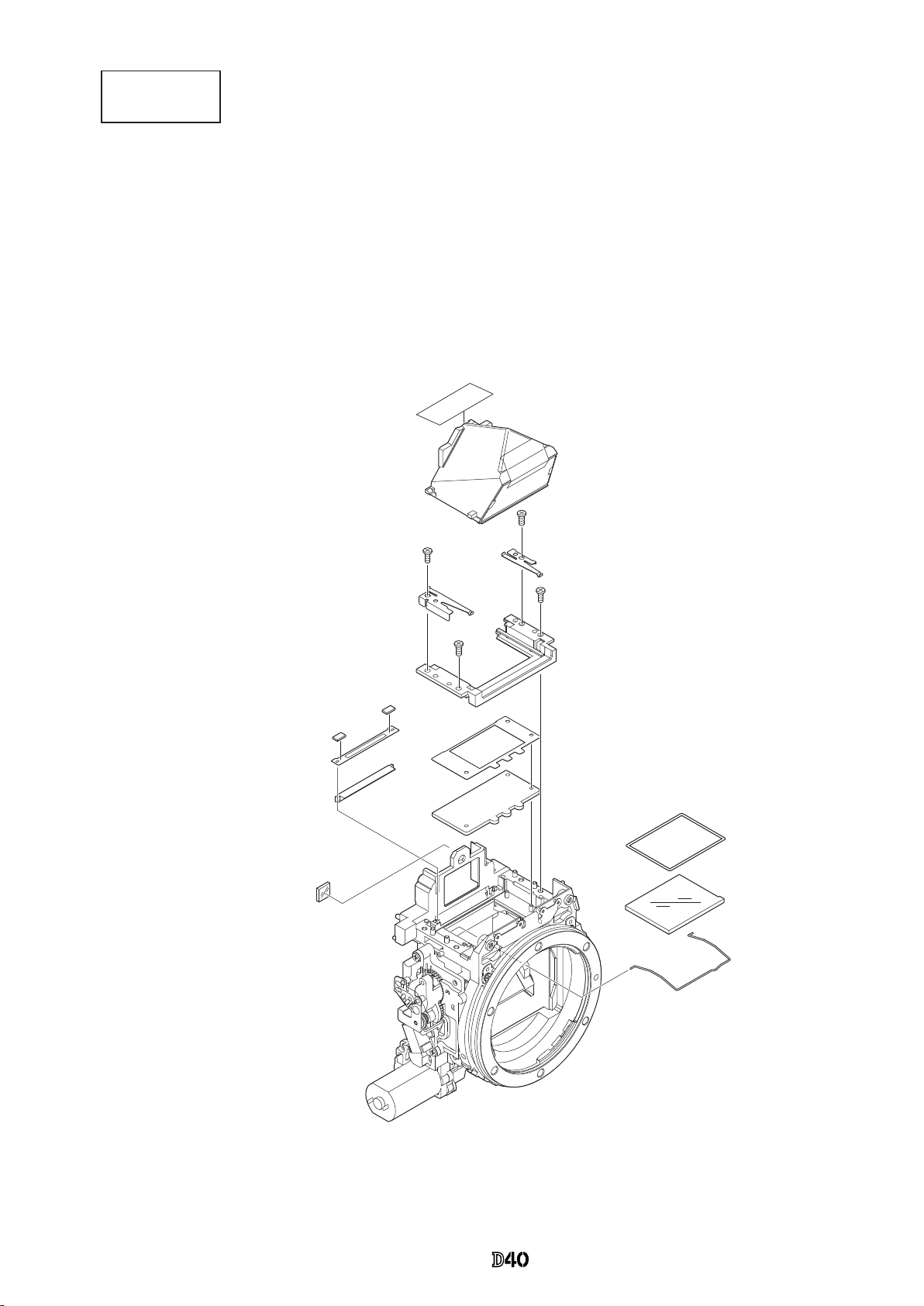
Penta unit
Screen areas
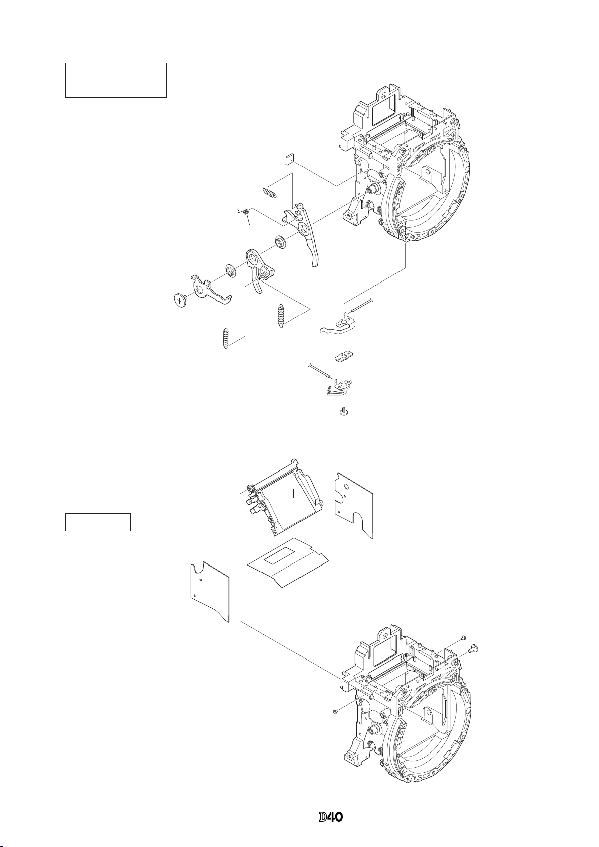
・
Take out the two screws (#635), and remove [#201] and [#202-1].
・
Remove the hollow penta prism unit (#B4) ,which is adheved by Super X.
・
Remove the nder eld frame 2 (#283).
・
Take out the two screws (#635), and remove the SI retaining unit (#B277).
・
Remove the nder eld frame 1 (#282-1).
・
Remove the in-nder display prism (#9).
・
Remove the SI display plate (#13-1).
・
Remove [#284], [#3], and [#297A].
#759
#B4
#635×2
#202-1
#201
#635×2
#B277
#282-1
#793×2
#283
#9
#13-1
#297A
#3
#284
#11
INC
Page 22
- D ・ -
VBA15001-R.3701.A
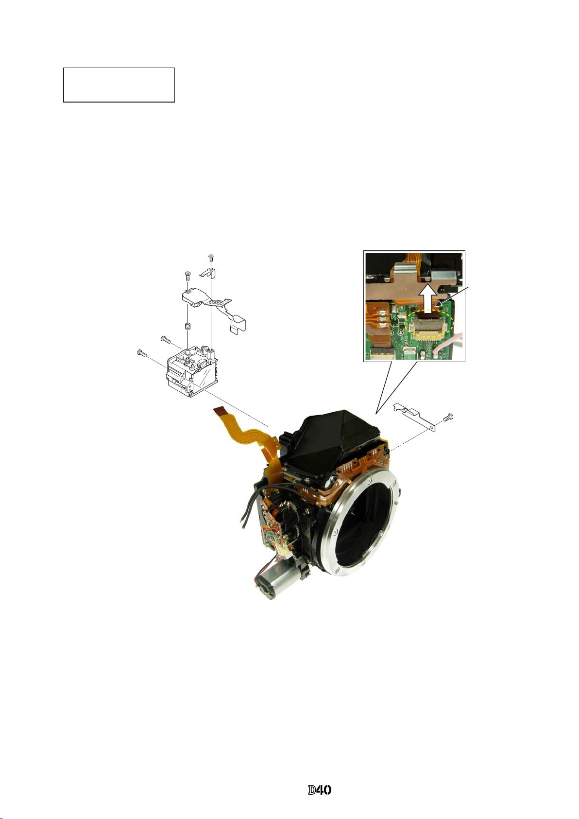
Connection-FPC
・
Take out the screw (#670).
・
Remove the connection-FPC (#1020) from the connector.
AF sensor unit
B2
2
#162×3
#161×3
AF sensor unit (#B2163)
・
Disconnect the AF sensor unit FPC from the connector.
・
Take out the three screws (#162) with hexagonal wrench (φ1.5mm).
The AF sensor unit (#B2163) and the three springs (#161) come off.
AF sensor unit FPC
#670
Connection-FPC (#1020)
INC
Page 23
- D ・ -
VBA15001-R.3701.A
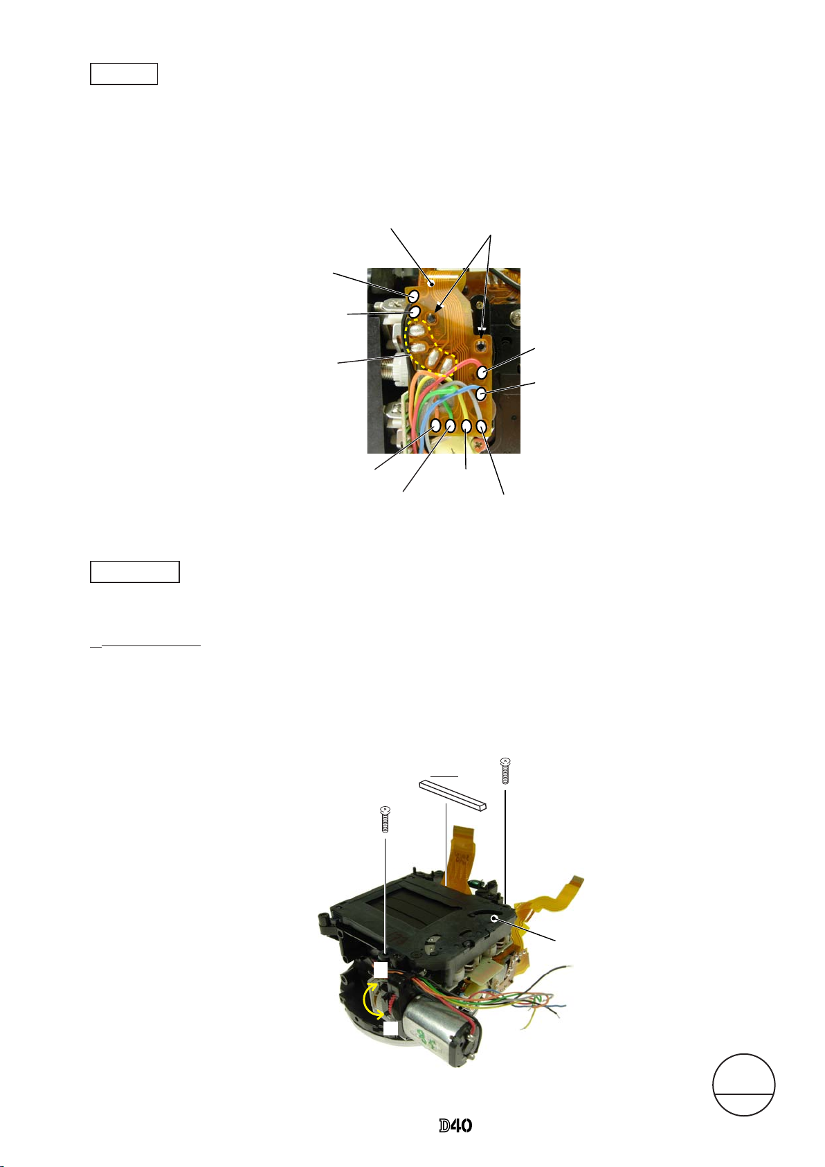
SQ FPC
・
Unsolder eight wires (connected from SQ, Fmin, and Mg).
・
Remove the four solder bridges.
・
Remove the SQ FPC by releasing from the bosses.
・
Turn the white gear in the direction of "A", and raise the mirror.
・
Remove [#757].
・
Take out the two screws (#635).
・
Remove the shutter unit (#31).
・
Turn the white gear in the direction of "B", and get the mirror down.
Shutter unit
Orange:Fmin
Green:SQ Gray:SQ
Yellow:SQ
Red:Mg
Blue:Mg
Black:Fmin
Black:SQ
Solder bridge ×4
Boss×2
SQ FPC
Changed page
△× 2
M
サービス
計画課
Feb.05.2007
A
#635×2
Shutter (#31)
B
△
(Addition)
#757
△
(Addition)
INC
Page 24
- D 0 ・ -
VBA15001-R.3701.A
・
Take out the two screws (#683).
・
Remove the in-nder LCD unit (#B2010).
#758
#683×2
#B2010
#276
#295
SB SW unit
・
Remove the three solder bridges.
・
Remove the SB SW unit.
・
Remove the front body FPC from the connector.
In-nder LCD unit
SB SW unit (#B1012)
Solder bridge ×3
Front body FPC
INC
Page 25
- D ・ -
VBA15001-R.3701.A
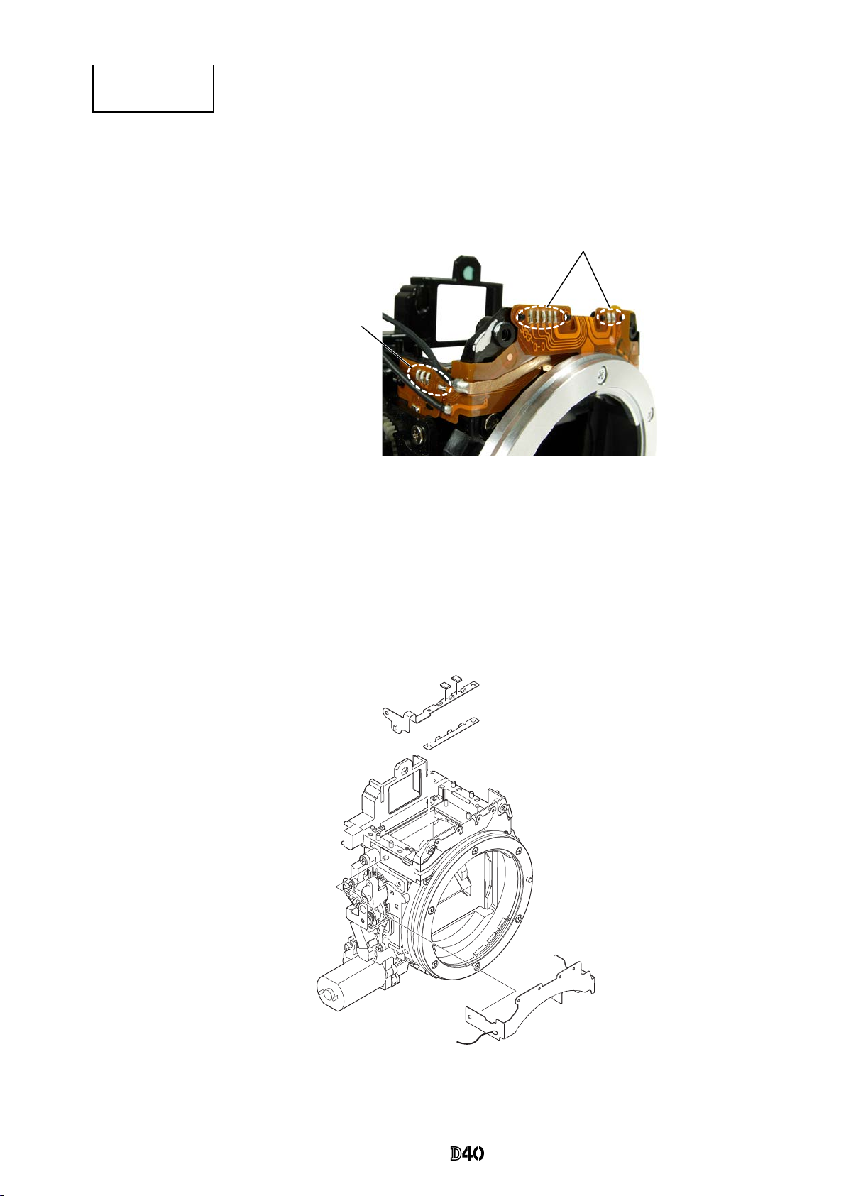
Front body FPC
SI LED-FPC
Solder bridge×7
Solder bridge×4
・
Remove the seven solder bridges and the other four solder bridges.
・
Remove the SI LED-FPC (#1011) and [#279].
・
Remove the front body FPC (#1009).
#278×2
#279
#1009
#1011
INC
Page 26
- D ・ -
VBA15001-R.3701.A
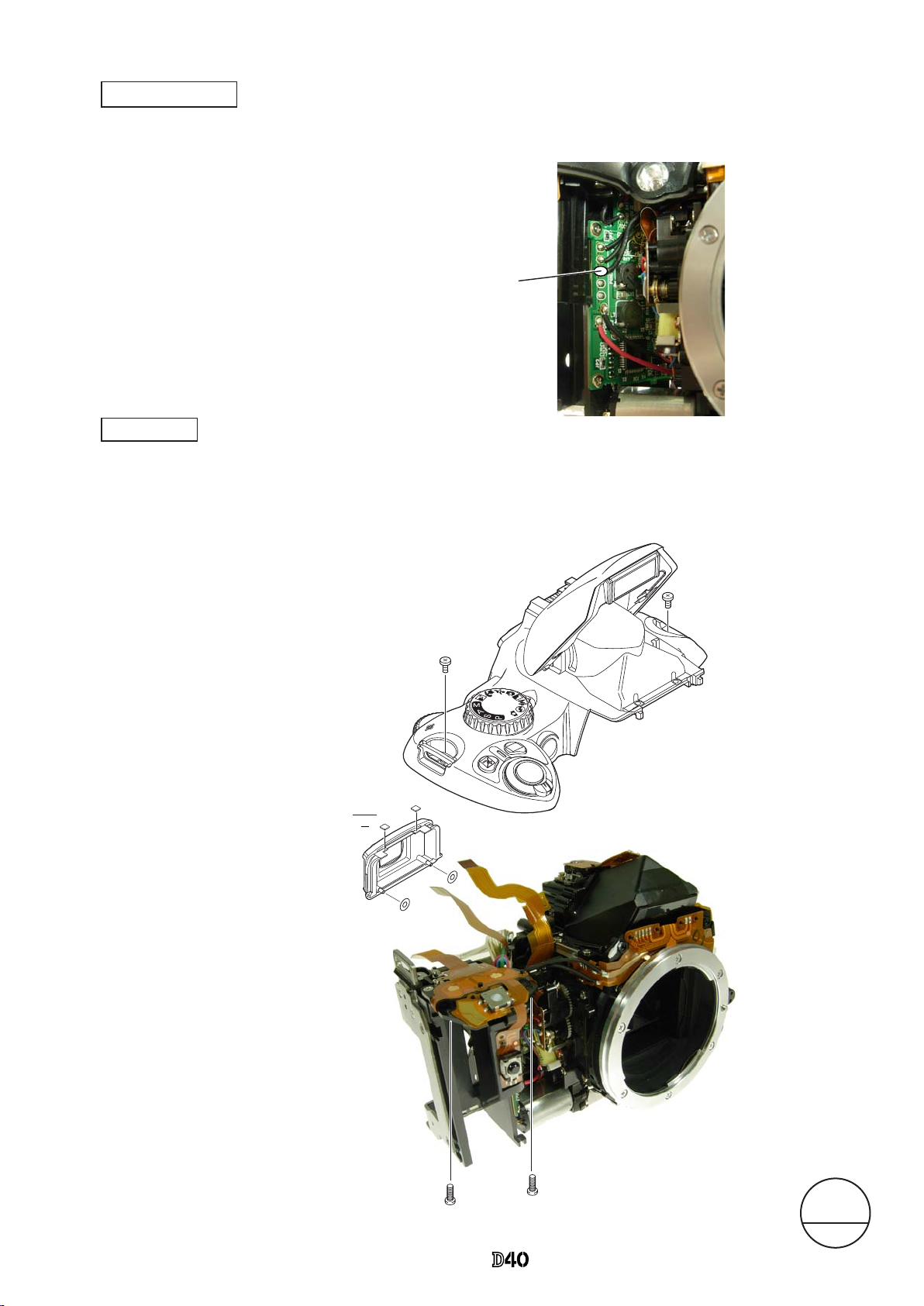
SQ PCB unit
・
Take out the three screws (#638).
・
Turn "① " part in the direction of the arrow, and remove the SQ PCB unit, while releasing from the roller
section.
Relay PCB
・
Unsolder the two wires (connected from SQ PCB unit).
・
Take out the screw (#607).
・
Remove the relay PCB.
#607
Red:SQ PCB unit
Black:SQ PCB unit
Relay PCB
#638×3
SQ PCB unit
SQ PCB unit
①
Roller
section
INC
Page 27

- D ・ -
VBA15001-R.3701.A
Bayonet /
A/M-change SW /
Lens-contact areas
#115-1
#119
#B116
#137-1
#B2113
#198
#189
#638×2
#112×3
#111
#660
#648×5
#607
#135-1
#621×2
INC
Page 28
- D ・ -
VBA15001-R.3701.A
#190
#205
#206
#209
#207-1
#210
#208-1
#639
#213
#204
#1106
#133-1
#136
#134-1
#645
#1105
#203-2
#B2231
#240-4
#239-2
#238-3
#199×2
#236-1
Aperture lever /
F-min SW areas
Mirror unit
INC
Page 29
- A ・ -
VBA15001-R.3701.A
#B2231
#240-4
#239-2
#238-3
#199×2
#236-1
Be careful NOT to bend here.
・
NOTE: For undescribed tapes and sponges here
in"Assembly", refer to PARTS LIST.
Assembly/ Adjustment
1. Front body
Mirror unit
・
With the mirror being raised, assemble the
pins and apply the adhesive (Super X) on
each pin.
#236
Apply the adhesive only
on 1/4 periphery of the
pin on mount side.
Adhesive Super X
Adhesive
Super X
INC
Page 30
- A ・ -
VBA15001-R.3701.A
#205 (white/short)
#204 (black)
#213 (white/long)
#190
#205
#206
#209
#207-1
#210
#208-1
#639
#213
#204
#1106
#133-1
#136
#134-1
#645
#1105
#203-2
Grease: LEN317A
Grease: LEN317A
Grease: LEN317A
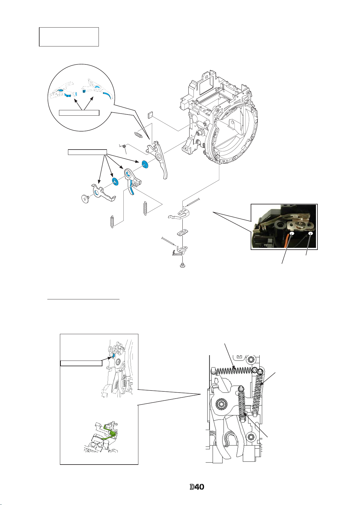
・
Hook [#205] and then [#204].
・
Hook [#213].
Mirror-down spring (#206)
hooking position
Aperture lever
F-min SW areas
Position for hooking spring
Orange:SQ FPC
Black:SQ FPC
INC
Page 31

- A ・ -
VBA15001-R.3701.A
SQ PCB unit
・
Move the roller section to the position as shown in Fig.①.
・
Turn "1" all the way to the end in the direction of the arrow. Then, Press "2" in the direction of "Lock".
・
Turn "3", and insert the roller section between [#207-1] and [#203-2].
・
Tighten the three screws (#638).
・
Press "2" in the direction of "Unlock".
Aperture control unit
約
6
0
°
#208-1
#207-1 #203-2
Roller section
Lock
Unlock
Fig.
①
3
1
2
Note: Be careful not to bend contact blade of F-min SW.
#638×3
SQ PCB unit
#253-1
Approx.60°
angle
INC
Page 32

- A ・ -
VBA15001-R.3701.A
Lens contacts unit
Release button unit
#115-1
#621×2
#119
#B116
#638×2
#198
#189
#B2113
INC
Page 33

- A ・ -
VBA15001-R.3701.A
Bayonet
Mount GND plate
#137-1
#648×5
③
#660
#112×3
#607
#135-1
①
④
⑥
②
⑤
#111
Height of Aperture lever
3.4±0.1 mm
#112
Grease: LEN317A
Height adjustment of Aperture lever
・
Measure the height of the aperture lever by using the tool (J18004).
Standard: 3.4±0.1mm
In case the value is out of standard, make an adjustment by bending the aperture lever.
Be careful NOT to bend the inner part of the lever when adjusting.
Aperture lever
・
Put [#135-1] and x it with the screw (#607).
・
Attach [#137-1].
・
Attach three pieces [#112].
・
Mount the bayonet (#111).
・
Tighten the screw (#660) and ve screws (#648)
in the order from ① to ⑥.
INC
Page 34

- A ・ -
VBA15001-R.3701.A
Relay-PCB unit
・
Mount the relay-PCB unit (#1004-1) in the direction for positioning, and x it with the screw (#607).
・
Arrange the wires as shown in "Fig. ①".
・
Solder the ve wires (connected from
SB-PCB, TOGO PCB, and SQ PCB unit).
・
Attach the front body-FPC (#1009), and connect it to the connector of the relay-PCB unit.
・
Attach the SI diffusing plate (#279) and SI-LCD FPC (#1011) and two pieces (#278).
・
Mount the SB SW unit (#B1012).
・
Make the three solder bridges.
#607
Red:SQ PCB unit
Black:SQ PCB unit
Relay-PCB
Direction for positioning
Red:SB PCB
Pink:TOGO PCB
Black:SB PCB
Front body FPC unit
SB SW unit (#B1012)
Solder bridge ×3
Relay-PCB
Super X
Fig.
①
Through the hole
Arrange around bosses.
Solder here.
#278×2
#1011
#279
#1009
Changed page
△× 1
M
サービス
計画課
Feb.05.2007
△
(Deletion)
INC
Page 35

- A ・ -
VBA15001-R.3701.A
・
Fix the in-nder LCD unit (#B2010) with the two screws (#683).
#758
#683×2
#B2010
#276
#295
・
Fold the contact-FPC down, and attach it by tting the four bosses in the holes.
・
Make seven solder bridges and four solder bridges.
Solder bridge×7
Solder bridge×4
Contact-FPC
In-nder LCD unit
INC
Page 36

- A ・ -
VBA15001-R.3701.A
・
Turn the white gear in the direction of "A", and raise the mirror.
・
Mount the shutter unit (#31), and x it with two screws (#635).
・
Turn the white gear in the direction of "B", and let the mirror down.
・
Attach [#757].
・
Attach the SQ FPC (#1014) by tting the bosses of the SQ-PCB unit in the holes.
・
Make ve solder bridges.
・
Solder the eight wires (connected from SQ, Fmin, and Mg).
Shutter unit
SQ FPC
Orange:Fmin
Green:SQ Gray:SQ
Yellow:SQ
Red:Mg
Blue:Mg
Black:Fmin
Black:SQ
Solder bridge×4
Wire arrangement:
Do NOT let all the wires
positioned across this line.
SQ FPC (#1014)
Boss×2
A
#635×2
Shutter (#31)
B
△
(Addition)
#757
Changed page
△× 2
M
サービス
計画課
Feb.05.2007
△
(Addition)
INC
Page 37

- A ・ -
VBA15001-R.3701.A
B2
2
#162×3
#161×3
#B2163
・
Turn three screws (#162) with
Hexagonal wrench (φ1.5mm) in
the order from ① to ③ all the
way lightly to the end, then give
each two-turns counterclockwise.
・
Attach the AF sensor unit FPC by conforming to the external shape, and connect it to the connector.
AF sensor unit FPC
・
Connect the connection-FPC (#1020) to the connector, and x it with the screw (#670).
①
②
③
AF sensor unit
Connection-FPC
#670
Connection-FPC (#1020)
・
Put three springs (#161) and mount the AF sensor unit [#B2163].
INC
Page 38

- A 0 ・ -
VBA15001-R.3701.A
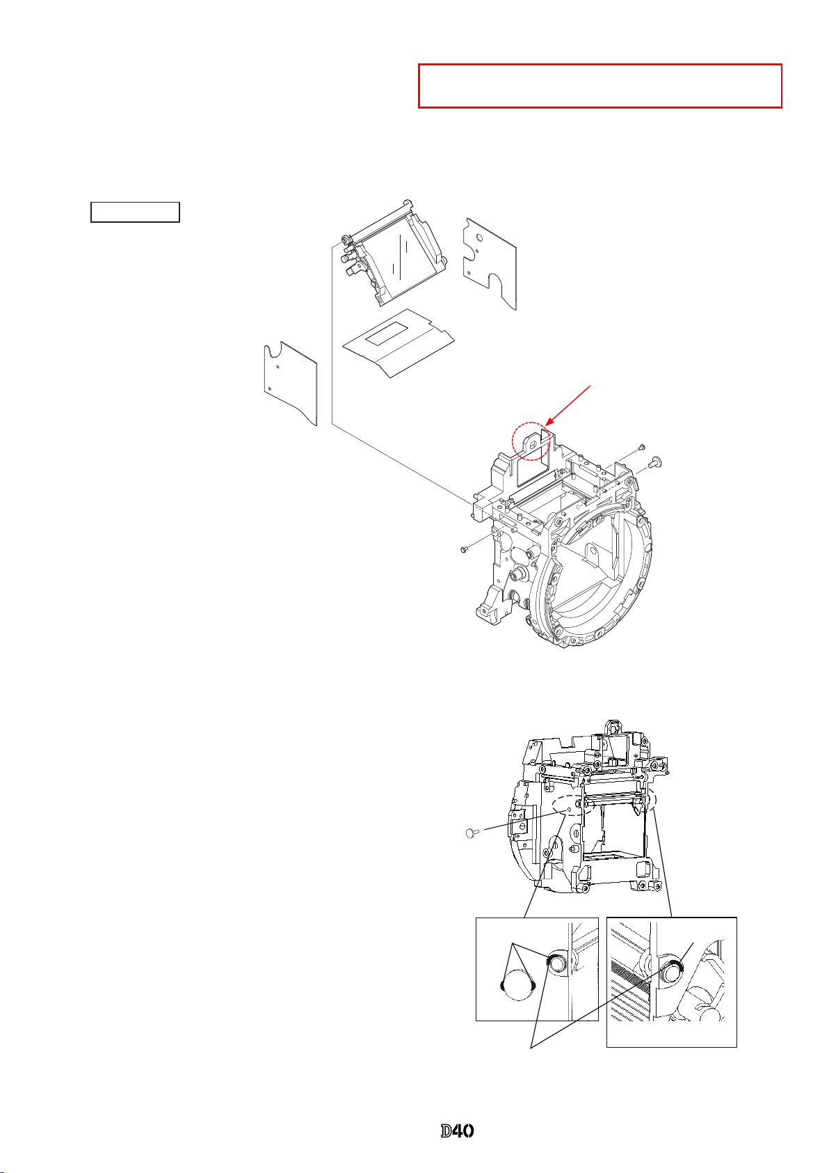
・
Mount SI (#13-1).
・
Mount the nder eld frame 1 (#282-1).
・
Attach the in-nder display prism (#9).
・
Mount the SI-retaining unit (#B277) and x it with two screws (#635).
・
Mount the nder eld frame 2 (#283).
・
Mount the hollow penta (#B4).
・
Attach the penta-retaining springs (#201 and #202-1) and x them each with the two screws (#635).
・
Mount [#284], then [#3] and [#297A].
#759
#B4
#635×2
#202-1
#201
#635×2
#B277
#282-1
#793×2
#283
#9
#13-1
#297A
#3
#284
#11
Penta unit
Screen areas
Adhesive: Super X
INC
Page 39

- A ・ -
VBA15001-R.3701.A
・
Mount the eyepiece barrel unit (#B261), and x it with two screws (#638).
・
Put the AE sensor adjusting-spring [#290] and AE FPC unit [#B2008], then x them with the screw (#291-1).
・
Put the AE sensor plate-spring (#285-3), and x it with the screw (#604).
・
Connect the FPC of the AE FPC unit (#B2008) to the connector.
・
Put the AE FPC retainer plate (#293), and x it with the screw (#607).
Eyepiece barrel unit
AE FPC unit
#B2008
#293
#607
#B2008
#638×2
#290
#291-1
#604
#285-3
#B261
INC
Page 40

- A ・ -
VBA15001-R.3701.A
Main mirror Sub-mirror
Left-right
deviation
±25′
__
Up-down
deviation
±5′
0′±3′
Distortion
6′ or less
6′ or less
Angle inspection and adjustment of Main mirror and sub-mirror
*
Device:
1.Main mirror 45° inspection and adjustment
2.Sub-mirror 47.75° inspection and adjustment
①
Collimator (J19110)
②
Reection mirror (J18362)
③
Optical parallel (J18037-2)
④
Hexagonal wrench
(J18037-2)
(J18362)
Main mirror
Eccentric pin for
the main mirror
Collimator
Bayonet
(J61218)
①
Collimator (J19110)
②
47.75° mirror tool (J61218)
③
Hexagonal wrench
Sub-mirror
Eccentric pin for
the sub-mirror
Collimator
Bayonet
Up-down
Left-right
Reference line
Width of line indicates deviation
*
Standard
*
Caution:
・
Before and after the adjustment, check the accuracy by moving the main mirror up- and downwards a few
times.
・
Check for the up-down deviation. In case the result is out of standard, make an adjustment by turning theCheck for the up-down deviation. In case the result is out of standard, make an adjustment by turning the
eccentric pin with Hexagonal wrench..
・
In case the the result of checking up-downward and right-leftward deviation is out of standard, the front plate
area or mirror unit should be defective.
・
In case inspection and adjustment are made for the mirror only in the front body, check again after assembling
the front body into the rear body.
INC
Page 41

- A ・ -
VBA15001-R.3701.A
・
Put the DC/DC lug plate (#159-1) at the nal stage, then x the battery box with the four screws (#615).
#694×2
#694×2
#143×3
#615×4
TA-0005
(7×15)
#B145×2
#159-1
Battery box
#607×3
#157×3
Buzzer unit
DC/DC lug plate
#607
Backup battery
Battery box
2. Rear body
DC/DC lug plate
Eyelet ring unit
Other small parts
INC
Page 42

- A ・ -
VBA15001-R.3701.A
・
Mount the SB-PCB, and x it with the screw (#687).
・
Solder the two wires (connected from DC/DC-PCB) and put them in the
groove for arrangement.
・
Adhere the main condenser with the adhesive double-coated tape by putting
in the direction for positioning.
・
Solder the two wires (yellow-circled) of the main condenser.
SB PCB
#687
Main condenser
#1043-3
SB-PCB
Red:DC/DC-PCB
Black:DC/DC-PCB
FPC:TOGO-PCB
Main condenser
#142
#141×2
#1043-3
#1076
#1077
Groove
Solder
Direction for
positioning
Black
Red
INC
Page 43

- A ・ -
VBA15001-R.3701.A
・
Mount the DC/DC-PCB, and x it with two screws (#670).
・
Put the wires in the groove for arrangement, and solder ve wires (connected from SB-PCB and Battery box).
Black:SB-PCB
Red:SB-PCB
Blue: Battery box (ID)
Red: Battery box (+)
Black: Battery box (-)
#670×2
DC/DC-PCB
・
Mount the remote block (#158-1), and x it with two screws (#683).
・
Attach SW-FPC [#B2006].
DC/DC PCB
Remote block
Groove
Groove
#683×2
#158-1
#B2006
#354
INC
Page 44

- A 1 ・ -
VBA15001-R.3701.A
・
Pass the wires of the relay-PCB through behind the main condenser, and assemble the front body into the rear
body.
・
Tighten four screws (#624).
3. Mounting of Front body on Rear body
Mount the front body on the rear body
・
Mount the bottom base plate unit (#B66-2) so that [#135-1] comes in front, and x it
with two screws (#691) and ve screws (#616).
Bottom base plate unit
Bottom base plate unit
(#B66-2)
#616×5
#691
#691
#135-1
Pull the wires from
here.
FPC must NOT
mount on this.
Direction for
positioning
#624×4
SB-PCB
Main condenser
Do NOT let wires
mount on the coil.
Changed page
△× 1
M
サービス
計画課
Feb.05.2007
△
(Addition)
INC
Page 45

- A 17 ・ -
VBA15001-R.3701.A
Note: For some bodies, washer(s) are already put on the attaching face of the CCD-bracket.
There are two cases as follows.
1. Purpose:To adjust the height of the camera body
There are indications by color marker on the CCD-PCB attaching face of the camera body side .
{Blue =0.02mm (#87), Red
=
0.01mm (#88), Green =0.06mm (#89)}
*
By adding the measured value to the thickness of washers, check if it is within the standard (48.59±0.015mm).
2. Purpose:To adjust the height of the CCD bracket
There are indications by marker on the CCD-bracket attaching face
One marking=Put three washers [#88(0.02mm)] at three places
Two markings=Put three washers [#87(0.1mm)] at three places
*
When the CCD PCB is replaced, remove the washers.
Any marking(s) of the three in the right "Fig.①"
=
Put the tracing-lm sheet (#84) in the marked place(s).
Surface plate
0
0" position of D40
0
40
0
70
0
50
30
90
20
10
10
Marking
Fig.
①
Inspection and Adjustment of Body back
* "0" positioning of the dial gauge
・
Measure three parts from the bayonet face to the CCD-
PCB attaching face.
Standard:48.59±0.015mm/ Parallelism: within 0.015mm
・In case it is out of standard, make an adjustment
by loosening screws that attach the front and rear bodies,
or by putting the washer(s) on the contact surface
between the front body and rear body.
①
Put the tool (J18001-1) on the surface plate, and set the dial gauge to "0".
②
Turn the index ring in the direction of the arrow, and set to the scale "8" from "0" that was set in ①. (This is
"0"-position of D40.)
③
Measure the body back based on "0" reference position of the index ring.
3.
△
(Addition)
Measuring point
△
(Revision)
Changed page
△× 2
M
サービス
計画課
Feb.05.2007
INC
Page 46

- A 1 ・ -
VBA15001-R.3701.A
・
Solder the two wires (connected from Mount GND plate and Front body FPC).
Red: Relay-PCB
Black: Relay-PCB
・
Solder the two wires (connected from Relay-PCB).
Black: Mount GND plate
Black: Front body FPC
DC/DC PCB
SB PCB
Changed page (Overall revision)
M
サービス
計画課
Feb.05.2007
INC
Page 47

- A 19 ・ -
VBA15001-R.3701.A
・
Fix [#322], [#B317], shoe base (#316), and [#318-1] with four screws (#654).
・
Fix the mode dial unit (#B5375), [#373], and [#372] with the screw (#640).
・
Fix the C/D unit (#B367) with two screws (#635).
・
Attach [#387-2] and AF/AE lock button (#5386-1).
Top cover FPC unit / other small parts
Assembly of Top cover
AUT
O
Grease:
LEN317A
#B5375
#635×2
#B367
#373
#372
#640
#326
#5386-1
#387-2
#654×4
#322
#318-1
#316
#B317
#311-1×2
#27-2
Grease:
LEN317A
Grease:
LEN317A
Adhesive Super X
Adhesive Super X
Direction for positioning
Changed page
△× 1
M
サービス
計画課
Feb.05.2007
△
(Revision)
Oil barrier: OS-30MF
INC
Page 48

- A 0 ・ -
VBA15001-R.3701.A
・
Mount the SB lower case unit (#B2302).
・
Arrange the wire (#1070-1) as shown below.
・
Mount the top cover FPC unit (#B2007-1), and x it with two screws (#635).
・
Make three solder bridges.
・
Mount the SB release base unit (#B2455), and x it with two screws (#607).
・
While releasing the two hooks, attach [#308-1].
・
Arrange the wires, and x them with the screw (#650).
SB lower case unit / SB release base unit / Buttons
#B2302
Hook ×2
#308-1
AUT
O
Grease: LEN317A
Grease: LEN317A
Grease: LEN317A
Grease: LEN317A
#B2007-1
#607×2
#635×2
#B2455
#650
Solder bridge ×3
Black : DC/DC PCB PCB
Arrange wires.
#1071-1
INC
Page 49

- A ・ -
VBA15001-R.3701.A
・
While pressing the SB case rotating shaft (#306-1), attach the SB-up spring (#305-1) by pushing it in the attach the SB-up spring (#305-1) by pushing it in the
direction of the arrow, then x it with the screw (#733).
・
Mount the release button unit (#B5350), [#347-1], and [#348], and x them with two screws (#605).
・
Attach the INFO button (#5383-1), ±aperture button (#5381), and rubber SW (#382-2).
#733
#305-1
#306-1
Put the
button with
ON-directed.
AUT
O
info
#B5350
#956
#347-1
#348
#605×2
#5383-1
#5381
#382-2
Grease: LEN317A
INC
Page 50

- A 22 ・ -
VBA15001-R.3701.A
・
Mount the AF-assist illuminator unit (#B325-1), and x it with the screw (#608).
・
Solder the two wires (connected from AF-assist illuminator unit).
#608
・
Make ve solder bridges.
・
Solder the seven wires (connected from SB lower case unit, DC/DC PCB and SB release base unit).
AF-assist illuminator unit
Top cover FPC / Wiring
Black : AF-assist illuminator unit
Uncoated wire: AF-assist illuminator unit
AF-assist illuminator unit (#B325-1)
Solder bridge
×5
Red: SB release base unit
Blue: SB release base unit
Red: SB lower case unit
Blue: SB lower case unit
Green: SB lower case unit
Black: SB lower case unit
Black: DC/DC PCB
△ (
Revision)
Black: SB release base unit
Changed page
△× 1
M
サービス
計画課
Feb.05.2007
INC
Page 51

- A ・ -
VBA15001-R.3701.A
・
Tighten two screws (#632).
#632×2
・
Mount the SB upper case (#5301) on the SB lower case unit.
SB upper case
#5301
Claw
・
Press the pop-up lever A part of the top cover unit, and raise the built-in SB.
SB upper case
Pop-up lever A part
SB lower case unit
INC
Page 52

- A 24 ・ -
VBA15001-R.3701.A
・
Solder the four wires
(connected from Top
cover).
Orange: Top cover
White: Top cover
Gray: Top cover
Black: Top cover
・
Solder the wire (connected from Top cover).
Black: Top cover
・
Mount the rubber eyecap (#B271).
・
Watching the wires and FPCs, mount the top cover.
・
Tighten two screws (#5737) and two screws (#635).
info
AUT
O
#5737×2
#B271
#635×2
#797×2
#796A~D×n
Top cover
DC/DC PCB unit
SB PCB
When the AE-CCD positioning is adjusted, solder the only four wires that connected from the
top cover to SB-PCB. Then, make a temporary assembly without mounting the rubber eye-
cap (#B271), and assemble up to Page A25.
Changed page
△×1
M
サービス
計画課
Feb.05.2007
△
(Revision) 0~n
INC
Page 53

- A ・ -
VBA15001-R.3701.A
・
Mount the CCD unit (#B3051-1) by following the direction for positioning, and x it with three screws (#631).
#B3051-1
#631×3
TOGO-PCB (#B2001-1)
Red:
Backup battery
Blue:
Backup battery
Gray:
Buzzer unit
Pink: Relay-PCB
・
Connect the harness.
・
Watching the wires and FPCs, mount the TOGO-PCB (#B2001-1).
・
Tighten ve screws (#663).
・
Solder ve wires (connected from Relay-PCB, Backup battery and Buzzer unit).
・
Connect the FPC to the connector at eight places.
#663×5
Harness
Direction for positioning
Gray:
Buzzer unit
Pull the wires from here.
TOGO-PCB unit: Back
CCD unit
TOGO PCB unit
Caution:
Some bodies have already washer(s) attached on
the mounting surface of CCD unit.
INC
Page 54

- A ・ -
VBA15001-R.3701.A
㧍
内部に高電圧部あり。カバーを外す 時は感電に注意すること。
カバーを外した後は、修理指針の指 示に従ってメインコンデン
サーの放電を必ず行うこと。
警告
Adjustment of AE CCD positioning
WARNING
Take extra care not to get an electric shock when detaching
covers.
After removing covers, be sure to discharge the main
condenser according to the instructions of repair manuals
.
*
Under the environment where the AE-CCD positioning is adjusted, use the reference body (and change the
environment depending on measured results).
・
In case the measured value is out of standard, check if there is no misalignment of the focus areas.
・
In case the measured value is out of standard, change the environment of measurements. (e.g. setting place/
direction, room brightness, etc)
Procedure
①
Only solder the four wires (connected from the top cover) on the SB-PCB. Assemble temporarily withoutolder the four wires (connected from the top cover) on the SB-PCB. Assemble temporarily without
attaching the screws (for xing the top cover) and mounting the rubber eyecap (#B271), then make a
temporary assembly of the front cover unit (#B5024) and rear cover with four screws (#5690).
②
Mount "AF50/1.4D" on the camera, and x them on the tripod horizontally.
③
Connect the camera and PC via USB cable (UC-E4).
④
Provide power by the battery tool (J61219).
**
Be careful NOT to cause a short-circuit at uncovered portions.
Attach the AE-CCD positioning tool (J15428) in the color viewer (J63070), and turn power ON.
Keep the 0.7-m distance between the front face of the AE-CCD positioning tool and the reference surface
of the camera. Set the camera AF to manual, and the focus ring to "0.7 m" by rotating it.
⑦
Start up the inspection and adjustment software for D40 (J18416), and select "Inspection and Adjustment
for AE CCD POSITION" then "Set Camera for AE CCD POSITION".
Looking through the viewnder, move the camera so that the focus areas of the camera coincide with the
circular holes of the AE-CCD positioning tool.
*
Set the camera and AE-CCD positioning tool horizontally.
⑧
Select "Inspection and Adjustment for AE CCD POSITION".
*
Cover the camera with a black cloth, etc, when measured.
⑨
Attach the metering FPC unit without tightening three screws (#291). Then give each screw two and half
turns counterclockwise. By following instructions on PC, make the position adjustment of AE-CCD by the
screws (a:#741, b:#291).
⑩
Fix the two screws with screwlock.
⑪
Fix the four locations of the AE CCD sensor-base with screwlock. (ref. Page A27 for the adhering posi-
tions.)
AE-CCD positioning
tool (J15428)
Attaching surface of
the imaging-PCB
Approx. 0.7
m
AF50/1.4
D
Color viewer (J63070)
INC
Page 55

- A ・ -
VBA15001-R.3701.A
#B2008Metering FPC unit
Main
condenser
2KQ/5W
Adhesive: Screwlock
a:
#741
b:
#291
⑫
After completing the adjustment, remove the temporarily-assembled rear cover and front cover. Then mount
the rubber eyepiece (#B271) and x the top cover with two screws (#5737) and two screws (#635).
Standard →
Reference screw
X-direction
→
a: Screw
Y-direction
→
b: Screw
Y-direction (b)
tightening
Y-direction (b) loosening
X
-direction (a)
tightening
X
-direction (a)
loosening
Discharge of Main condenser
・
Discharge currents from both terminals of the main condenser.
INC
Page 56

- A ・ -
VBA15001-R.3701.A
Standard: 0.14~0.5mm
Covers
Gap adjustment of SB lighting unit
・
In case the result is out of standard, pop the SB unit up
and make an adjustment by turning the adjusting dial
with Hexagonal wrench.
Adhesive: Super X
#5610×2
#5610×2
#5074
#29-2
#26-2
#131
#626
#5120
#670
#B5024
・
Assemble the front cover unit
(#B5024) together with the
Fmin coupling block (#131).
Adjusting dial
INC
Page 57

- A ・ -
VBA15001-R.3701.A
A
A
#402-3
#403
#5401-7
#5424-4
#5425-3
#5426-3
#5427-3
#421-2
#405×2
#1037
#5429-2
#423-2
#408
#5412-1
#5418-5
#413-1
#414
#1016-3
#453
#452
#451×2
#406-3
#750
#670×3
#630×3
#5431-1
#433
#5432-1
#404×2
#448
#407-2×2
#B5431
#5681×2
Direction for positioning
Rear cover
Direction for positioning
INC
Page 58

- A 30 ・ -
VBA15001-R.3701.A
・
Connect the TFT-PCB connection-FPC to the connector.
・
Mount the rear cover.
・
Tighten four screws (#5690) and two screws (#5618).
Rear cover (continued)
Rear cover
#5690×4
#5618×2
TFT-PCB connection-FPC
NK
Changed page
△×1
M
サービス
計画課
Feb.05.2007
△
(Addition)
INC
Page 59

- A ・ -
VBA15001-R.3701.A
J18267
Flash meter
Caution:
When the inspection and adjustment are made with the shutter tester, turn the tester ON to light a lamp, and carry out the
aging for 3-5 minutes.
D40 adjustment FD: IBM 3.5
★
AE-CCD positioning tool (J15428)
Set up in front of color viewer (J63070)
AF28/2.8D
Shutter tester (EF-1) (J19123)
★
: New tool
D40 battery
tool (J61219)
Caution: When performing “Adjustment for BATTERY
CHECK LEVEL” use the D40 battery tool (J61219).
Stabilized power source(Set value = 7.4V
0.3Ω 5.0A)
+ D40 battery tool (J61219) or
AC adapter (EH-5)
+
Power connector (EP-5)
★
To USB terminal
USB cable: UC-E4
J18416
(except Image unit)
Accuracy inspection and adjustment (Camera body)
INC
Page 60

- A ・ -
VBA15001-R.3701.A
D40 Inspection and Adjustment Software (J18416)
This inspection and adjustment software runs on Windows.
Install the software by following the below procedure.
<Operating environment>
Check the following operating environment which is required for installing this program on PC.
PC IBM PC/AT compatible
OS Windows XP Professional Edition, Windows XP Home Edition,
Windows2000,
CPU Pentium II 300MHz ~
RAM (memory) 256 MB or more
HD 6MB-or-more free disk space is required when installing
Monitor resolution 1024 × 768 pixels or more
Interface
※ USB interface (V1.1, 2.0)
As long as the above hardware requirements are met, any PC such as desktop or laptop, etc is available.
< Cautions in starting program >
When starting this program, close all the other applications.
If some other applications are running, this program may not be activated.
< File >
D40.exe Application execution le
NkdPTP.dll Library le: USB communication application extension le for Windows XP
NkdPTPDi.dll Library le: USB communication application extension le for Windows 2000
PTPC Driver le storing folder for PTP: for Windows 2000
INC
Page 61

- A ・ -
VBA15001-R.3701.A
<Procedure for installation>
The le (PD40.EXE) of this program is provided via FD or e-mail.
Because this is the self-extracting le, decompress the le before installing, and follow the next procedure.
1. Create a folder for install under any name in any drive.
(e.g.)C: ¥D40
2. Paste the le (PD40.EXE) in the created folder.
INC
Page 62

- A ・ -
VBA15001-R.3701.A
3. Double-click on the pasted le to display the following screen.
Press the OK button, then decompression starts.
4. When the decompression of le is nished, the le (D40.exe) is created.
5. The install is completed.
INC
Page 63

- A ・ -
VBA15001-R.3701.A
4.Click "Yes".
If this program is used by the USB interface, installing the USB driver is necessary.
But if the OS is "Windows XP", the driver is already preloaded so it is not necessary to install it.
1. Set the USB of camera to "PTP".
(SETUP menu → USB setting → PTP)
2. Connect the camera and PC by USB cable.
Turn camera ON.
3. When "Add New Hardware Wizard" is displayed, click "Next".
< Procedure for installing USB driver >
5. Click "Reference". Select “C:\D40\PTPC" of C drive, and click "OK".
6. Reboot the PC and the install is completed.
INC
Page 64

- A ・ -
VBA15001-R.3701.A
. When the "Version" button at the lower-left is pressed, the program version will be displayed.
. Select each item button according to operation.
Follow the instructions on the next screen that will be shown after pressing the item button.
. To nish the program, press the "Close (×)" button in the right-hand corner of the screen or "QUIT.".
<Start-up of Program>
1. Double-click the le (D40.exe), then Inspection and adjustment program for D40 starts.
2. To display in Japanese, select the radio button "JAPANESE" in "LANGUAGE" in the lower right-hand corner
of the screen.
However, this is not properly viewed in the English OS.
INC
Page 65

- A ・ -
VBA15001-R.3701.A
《
USB connection communication
》
①
AE CCD alignment inspection and adjustment (ref. Page A26, A27 for details
)
②
AE accuracy inspection and adjustment
③
Aperture accuracy inspection
④
Adjustment for battery check level [Use the D40 battery tool (J61219) and stabilized power supply.]
Built-in SB ash inspection and adjustment
〔Tools required〕ref. Page A31.
AE inspection and adjustment
・
Battery check voltage level adjustment
Connect the D40 battery tool (J61219) to the camera, and turn the communication change-SW to ON. Then
make adjustment.
・
Built-in SB ash inspection and adjustment
Set the distance between camera and ash meter to 1 m, and inspect and adjust the light volume of the built-in
SB. (ref. adjustment software for details)
・
AE accuracy inspection and adjustment
When AE accuracy inspection and adjustment is made,
Two types of lenses (AF50/1.4D and AF28/2.8D) are used.
Caution:
AE accuracy is not inspected in the traditional manner that uses the exposure value of the shutter tester. The
metering value is displayed on PC screen.
AF inspection and adjustment
Note: When using the adjustment software for the rst time, prepare three cameras of D40 and measure by
"WRITING of AF ADJ. LENS OFFSET VALUE" on the main menu.
<< USB connected communication >>
①
AF accuracy adjustment (Make the overall following adjustment.)
②
YAW, PITCH inspection and adjustment
③
LARK adjustment (inc.
CCD output adjustment)
④ AF shift adjustment
〔Tools required〕
1. When adjusting for all adjustment items
ref. Page A31.
2. When inspecting AF accuracy
① AF
adjustment Z lens (J18266)
②
AF adjusting tool (J15259
)
③
Lens holder (J15280)
④
AF accuracy measuring chart D40 (
J18415)
Chart illuminator for AF
(J15264)
3. When adjusting YAW, PITCH
YAW, PITCH tool(J18230
)
4. When adjusting LARK
The above tool when inspecting AF accuracy
In "AF shift adjustment", the distance from the bayonet reference plane to the imaging area (CCD) is calculated
by the actual shot photo, and its error is recorded in EEPROM as compensation amount, and adjusted.
INC
Page 66

- A 3 ・ -
VBA15001-R.3701.A
#297A 1K602-153 Innity-focus adjusting washer
(T=0.1) 0.10mm
#297B 1K602-154 Innity-focus adjusting washer
(T=0.2) 0.20mm
・
Mount the bottom cover.
・
Fix it with four screws (#5735) and ve screws (#5674).
Bottom cover
・
Replace the nder screen with the innity focus adjustment screen (J15410), and use the reference lens (J18010)
and read the value. In case it is out of standard, increase or decrease washers (#297A, #297B) for adjustments.
Caution: When (J15410) is put in to replace the nder screen, put it with the silver spacers upward, which are
attached on both sides.
∞ Innity focus inspection & adjustment
Reference line
"0" position
J18010
Standard:
±0.06mm
1 scale
=
0.01mm
)
Changed page
△× 1
M
サービス
計画課
Feb.05.2007
#5735
#5674×2
#5735
#5674
#5674
#5735×2
#5674
Bottom cover
Grease:MZ-00S
△
(Addition)
INC
Page 67

- A ・ -
VBA15001-R.3701.A
1. D40 adjustment software and updates
Adjustments
Replacement parts
Writing of
EEPROM
xed
values
AE CCD
positioning
adjustment
AE
accuracy
inspection &
adjustment
Aperture
accuracy
inspection
Battery
check volt-
age level
adjustment
Built-in SB
light volume
inspection &
adjustment
AF
accuracy
inspection &
adjustment
Shutter unit
TOGO PCB unit
(
Firmware
MAIN,RISC)
○ △ ○ ○ ○ ○ ○
Relay-PCB
(
EEPROM
)
○ △ ○ ○ ○ ○ ○
AF sensor unit
○
Top cover or
SB lower case unit
○
DC/DC PCB unit
○ ○
Metering FPC unit
○ ○
Aperture control PCB
unit
○
*
1. Make an inspection.
*
2.When only TOGO PCB unit is replaced without replacing the relay-PCB, be sure to update the MAIN and RISC
rmware before writing the xed values.
Caution: If the rmware cannot be recognized by MAIN rmware name (AD40XXXXXX.bin), change the rmware name
to (A330XXXXXX.bin), and update again. If the RISC rmware name (R330XXXX.BIN) is used, update by
following the procedure for forcible updating on Page A49.
When both TOGO PCB and relay-PCB are replaced at the same time, write the xed values and update the MAIN
and RISC rmware. Then, write the xed values again and make an adjustment.
*
*
2
*
*
2
Necessary adjustments when parts are replaced
INC
Page 68

- A 0 ・ -
VBA15001-R.3701.A
2. Shooting image adjustment software and Software updates
Adjustments
Replacement
parts
Writing
of xed
values
Sensi-
tivity
Gr/Gb com-
pensation
adj. (R/B
lter)
Sensitiv-
ity ratio
Pixel
defect
com-
pensa-
tion -
Black
point
Pixel
defect
compen-
sation -
White
point
Writing
of TFT
xed
values
Factory
default
setting
Shutter unit
Relay PCB
(
EEPROM
)
AF sensor unit
DC/DC PCB unit
Metering FPC unit
TOGO PCB unit
(
Firmware MAIN,RISC)
○ ○ ○ ○ ○ ○ ○ ○
CCD/FPC PCB unit
○ ○ ○ ○ ○
TFT monitor
○
*1.
When TOGO-PCB unit is replaced, be sure to update the rmware before writing the xed values.
When both TOGO-PCB unit and relay-PCB are replaced at the same time, write the xed values before updating,
and after updating the MAIN and RISC rmware, write the xed values again.
*2.
When TOGO PCB is adjusted, the xed values are written automatically.
*
1
*
2
INC
Page 69

- A ・ -
VBA15001-R.3701.A
Shooting Image Adjustment
1. Summary
When D40 shooting image-related and listed parts on Page A40 are replaced, be sure to make an adjustment
by the shooting image adjustment software for D40 (J65094). The details of its function and how to use this
software are as follows:
2. Adjustment software function
① "Sensitivity" adjustment
② Gr/Gb compensation adjustment (R/B lter) / Line crawl adjustment
③ "Sensitivity ratio" adjustment
④ Pixel defect compensation - black point
Pixel defect compensation - white point
Getting reference values
⑦ Factory default setting
⑧ Checking of the adjustment value
⑨ Reading of RISC version
⑩ TFT adjustment
※ When the adjustments from ① to ③ are made, get in advance the reference values of by using the
reference body, then perform the adjustments.
3. Hardware requirements
OS: Windows2000, WindowsXP
Japanese or English OS
PC: CPU Pentium Ⅱ or more
Memory 256MB or more
USB1.1 or 2.0
Screen size: 1024×768 pixels or more
4. How to set up
Create any directory in the hard disc (except desk top) of PC, and copy the following les.
・D40IMG.exe・・・・・・・Application le
・D40STD.DAT ・・・・・・ Standard le
・NkdPTP.dll・・・・・・・・USB-communication application extension le for WinXP
・NkdPTPDi.dll・・・・・・・USB-communication application extension le for Win98SE and Win2000
・CCDFLG.DAT・・・・・・・ Fixed value data for TOGO-PCB adjustment
・CCDINIT.DAT ・・・・・・・Fixed value data for TOGO-PCB adjustment
・TFTFLG.DAT ・・・・・・TFT xed value data
・TFTINIT.DAT ・・・・・・・TFT xed value data
※ Be sure to copy the above le in the same directory.
5. Install of USB driver
When this software is used, the USB driver is necessary. However, this install becomes unnecessary if the D40
camera inspection and adjustment program was installed including the USB driver.
Also, WindowsXP OS has already the USB driver, so this install anew is not necessary, either.
INC
Page 70

- A ・ -
VBA15001-R.3701.A
Fig.2
Fig.1
6. Basic usage
(1) Execute "D40IMG.exe" to start up the main screen. (ref. Fig.1)
(2) Select ENGLISH / JAPANESE in Language to display any menu. (ref. Fig.2)
(3) Click the button to start adjustments.
※ When the adjustments from ① to are made, calculate to get the reference values ( ) by using the
reference body beforehand, then perform the adjustments.
(4) Follow the instructions on screen.
(5) To complete the procedure, click "QUIT" button or "X" button at the upper-right corner of the menu.
INC
Page 71

- A ・ -
VBA15001-R.3701.A
7. Required equipment and conditions
※ AC adapter EH-5, Power connector (EP-5) and USB cable (mini B type) UC-E4 are used for all
adjustments so they are not specied in the list.
Item Required device Setting/Remarks
1 Sensitivity adjustment
・5100K color viewer J63070J63070
(ex-model viewer J63049 is also available.)
・Luminance meter BM-3000 J63068
・Tool lens (to x aperture) J61185
・ND lter (ND8×2)ND8×2)
Luminance LV13 equivalent
Aperture F8
52 mm,
Use the packaged product; 6-step light
reduction
2 Gr/Gb compensation adjustment
(R/B lter)
/ Line crawl adjustment
・5100K color viewer J63070J63070
(ex-model viewer J63049 is also available.)
・Luminance meter BM-3000 J63068
・Tool lens (Fixed aperture) J61185
・SP3 (R lter) J63087
・SP1 (B lter) J63085
Luminance LV13 equivalent
Aperture F5.6
3 Sensitivity ratio adjustment
・ Shutter tester
・Tool lens (to x aperture) J61185
Luminance LV12
Aperture F5.6; No lter
4 Pixel defect compensation -
black point
・5100K color viewer J63070
(ex-model viewer J63049 is also available.)
・Luminance meter BM-3000 J63068
・Tool lens (to x aperture) J61185
Luminance LV13 equivalent
Aperture F5.6; No lter
5 Pixel defect compensation -
white point
Body cap or lens capdy cap or lens cap Environmental temperature approx. 20
- 25℃
6 Getting of reference values Same as "Sensitivity adjustment" and "sen-
sitivity ratio adjustment".
7 Factory default setting None
8 Checking of adjustment value None
9 Reading of RISC version None
10 TFT adjustment None
★ New tool
INC
Page 72

- A ・ -
VBA15001-R.3701.A
8. Summary
The summary on each adjustment is as follows:
① Sensitivity adjustment
Camera is faced to the color viewer of LV13 equiv. with ND lter (-6 steps) being put between them, and
the adjustment is made by changing the ampgain so that G output can fall in the standard range. The gain
value is adjusted so that the G output average value (Average of Gr/Gb) in the center (300×300 pixels) can
reach the target output level (approx. 960LSB). The actual adjustment of the gain value is made only under
the condition of ISO200 and ISO1600, and the medium sensitivity is calculated by the adjustment values
of these 2 conditions.
For target output level, G output average of sensitivity reference value (ISO200) is used, which was
calculated by the reference body.
② Gr/Gb compensation adjustment (R/B lter) / Line crawl adjustment
Camera is faced to the light-emitting box (color viewer) of LV13 equiv. with SP3 (R lter) or SP1 (B lter)
being put between them, and the adjustment is made so that the difference in G output average between
B-G line and G-R line, when the whole screen is divided in areas, can fall in the standard range.
③ Sensitivity ratio adjustment
With the shutter tester of LV13, the adjustment is made so that the R/G, B/G output becomes the same
as the output ratio of the sensitivity ratio reference value that was calculated by the reference body. The
adjustment is made only under the condition of ISO200, and the average value of the center (300 pixels ×
300 pixels) is used.
④ Pixel defect compensation - black point
When pixels of which the output level is under specied value with LV13 equiv., are detected, the
coordinates of the detected pixels are rewritten as pixel defect compensation data.
Pixel defect compensation - white point
Shots are taken on the dark surface. In case the pixel output is found to be beyond the standard value, the
detected pixel coordinate is additionally written as the pixel defect compensation data.
Getting of reference values
・Sensitivity reference value calculation
The reference body is faced to the color viewer of LV13 equiv. with the ND lter (-6 step) being put
between them. Then, store the G output average value of the center (300 pixels × 300 pixels) is stored in
the D40BSD.DAT le as the sensitivity reference value.
・Sensitivity ratio reference value calculation
The reference body is faced to the shutter tester of LV 12 equiv. (without lter). Then, the sensitivity
ratio reference value GR and GB is calculated, based on the G/R/B output average of the center (300
pixels × 300 pixels), and they are stored in the D40BSD.DAT le.
It is necessary to calculate the reference values of "Sensitivity" and "Sensitivity ratio" in order to prevent
the color temperature uctuation caused by color viewer's changes over time from affecting the results of
the shooting image adjustment. By using the reference body, calculate the reference values once in about
every 3 months, when the uorescent of the color viewer is replaced.
INC
Page 73

- A ・ -
VBA15001-R.3701.A
⑦ Factory default setting
This selects and sets the language and video mode at the time of shipping products.
⑧ Checking of adjustment value
The adjustment value is conrmed, functioning as substitute for the traditional "READING AND
REWRITING OF EEPROM DATA.".
⑨ Reading of RISC version
The RISC rmware version is displayed.
⑩ TFT adjustment
None
INC
Page 74

- A ・ -
VBA15001-R.3701.A
9. Procedure
9-1. TOGO PCB adjustment
● Calculate the "Sensitivity" and "Sensitivity ratio" reference values by using D40 reference body beforehand,
then perform the adjustments. (ref. 9-4.)
● For shooting image adjustment, make all items from ① to ③ . The adjustments from ① through ③ are all
programmed to be executed in serial order. When 1 item is completed, the software automatically goes on
to the next adjustment.
● In case adjustments are interrupted by NG, the adjustments can be continued again after NG. As for
adjustments that were ended with OK, saving the adjustment values in EEPROM and updating the ash
memory are completed.
*
Note: Adjustments are not possible without resetting "Custom setting" of this camera.
Before the adjustments, record the details of "Custom setting" set by customers if necessary.
Start adjustments
・Provide the power for the camera via AC adapter.
・Reset "Custom setting".
・Set "PTP" mode by Setup menu.
・Set the focus mode to M, exposure mode to M, and the exposure compensation to "0" of the camera.
・Connect the camera and PC via USB cable.
・Set the luminance of the color viewer to LV13 equivalent.
・Set the shutter tester to LV12. (for sensitivity ratio)
① Sensitivity adjustment
・Click "SENSITIVITY ADJUSTMENT" of the main menu on screen.
・Click "Start".
・Setting conditions are indicated.
・Attach the tool lens (Aperture F8) and ND lter (ND 8× 2)to the camera.
・Get the camera closest to the center of the illuminated surface of the color viewer.
・Click "OK".
・The adjustment starts. When it is completed, "OK" is displayed.
・Click "OK".
・Click "Next".
② Gr/Gb compensation adjustment (R/B lter)
・Click "Gr/Gb COMPENSATION ADJ (R/B FILTER)" on the menu.
・Setting conditions are displayed soon.
・Attach the tool lens (Aperture F5.6) and SP3 (R lter) to the camera.
・Get the camera closest to the center of the illuminated surface of the color viewer.。
・Click "OK".
・The adjustment starts. When it is completed, the next conditions are displayed.
・Attach the tool lens (Aperture F5.6) and SP3 (B lter) to the camera.
・Get the camera closest to the center of the illuminated surface of the color viewer.。
・Click "OK".
・The adjustment starts. When it is completed, the next conditions are displayed.
INC
Page 75

- A ・ -
VBA15001-R.3701.A
[・Attach the tool lens (Aperture F5.6) and SP1 (B lter) to the camera.]
・Get the camera closest to the center of the illuminated surface of the color viewer.
・Click "OK".
・The adjustment starts. When it is completed, the next conditions are displayed.
・Attach the tool lens (Aperture F5.6) and SP3 (R lter) to the camera.
・Click "OK".
・The adjustment starts. When it is completed, "OK" is displayed.
・Click "OK".
・Click "Next".
③ Sensitivity ratio adjustment
・Click "Start".
・Setting conditions are indicated.
・Attach the tool lens (Aperture F5.6) to the camera (without lter).
・Get the camera closest to the center of the illuminated surface of the shutter tester (LV12).
・Click "OK".
・The adjustment starts. When it is completed, "OK" is displayed.
・Click "OK".
・Click "Next".
9-2. Pixel defect compensation
④ Compensation - black point
・Set the color viewer luminance to LV13 equiv.
・Provide the power for the camera via AC adapter.
・Reset "Custom setting".
・Set "PTP" mode by Setup menu.
・Set the focus mode to M, exposure mode to M, and the exposure compensation to "0" of the camera.
・Connect the camera and PC via USB cable.
・Click "Start".
・Setting conditions are indicated.
・Attach the tool lens (Aperture F5.6) to the camera (without lter).
・Get the camera closest to the center of the illuminated surface of the color viewer.
・Click "OK".
・When the adjustment starts, pixel defects are detected, displaying the number of pixels and addresses.
・When it is completed, "OK" is displayed.
・Click "OK".
*
Note: In some cases, NG occurs due to dusts on the CCD.
Be sure to clean the CCD surface before adjustments.
INC
Page 76

- A ・ -
VBA15001-R.3701.A
9-3.
Compensation - white point
・Check the environmental temperature (approx. 20-25°C).
・Click "Start".
・Setting conditions are indicated.
・Cap the camera with the body cap or lens cap to shield light from the mount.
・Click "OK".
・When the adjustment starts, pixel defects are detected, displaying the number of pixels and addresses.
・When it is completed, "OK" is displayed.
・Click "OK".
・Click "End".
9-4.
Getting of reference values
・Select "OBTAIN REFERENCE VALUE." of the menu on screen.
・Click "Start".
・Click "Start" again.
・The message of setting conditions is displayed.
・Click "OK".
・Attach the tool lens (Aperture F8) and ND lter (ND 8× 2) to the camera.
・Get the camera closest to the center of the illuminated surface of the color viewer.
・The adjustment starts, and getting "Sensitivity" reference value is completed.
・Click "OK".
・Click "Next".
・Click "Start" of "OBTAIN RATIO REFERENCE VALUES".
・Attach the tool lens (Aperture F5.6). (Remove the lter).
・Get the camera closest to the center of the illuminated surface of the shutter tester (LV12).
・The adjustment starts. When it is completed, the sensitivity and sensitivity ratio reference values are stored
in the standard setting le (D40BSD.DAT).
・After this procedure, when the shooting image adjustment is made, the sensitivity and sensitivity ratio that
were calculated this time are used.
※ Calculate the sensitivity and sensitivity ratio reference values once in about every 3 months, and when the
uorescent of the color viewer is replaced.
9-5. TFT adjustment
Writing of TFT xed values
・Click "REWRITING THE TFT FIXED VALUE".
・The message "Will you rewrite the CAMERA?" appears.
・Click "Yes".
・Writing is completed.
・Click "OK".
INC
Page 77

- A ・ -
VBA15001-R.3701.A
Flicker adjustment
・Usually default value is set and adjustment is not necessary.
・If icker is recognized by visual check, adjust by the slider so that no icker is visible.
・Remove the USB cable from the camera, then remove the AC adapter without turning the camera OFF.
Hue adjustment
・Usually default value is set and adjustment is not necessary.
・If some problem is found with hue by visual check, adjust and correct it by the slider.
・Remove the USB cable from the camera, then remove the AC adapter without turning the camera OFF.
Brightness adjustment
・Usually default value is set and adjustment is not necessary.
・If some problem is found with brightness by visual check, adjust and correct it by the slider.
・Remove the USB cable from the camera, then remove the AC adapter without turning the camera OFF.
9-6. Reading of RISC version
・Click "RISC VERSION" of the menu on screen.
・RISC version is displayed.
9-7. Procedure for upgrading RISC rmware: for upgrading RISC rmware:
・ After preparing the SD card, copy the latest version ( BD40XXXX. BIN) into the root directory.
・ Insert the SD card, and select "FIRMWARE VERSION" from the SETUP menu.
・ Follow the instructions on screen for version upgrading. It takes approx. 3-4 minutes.
・ Check the version of rmware by "RISC VERSION" of the image adjustment software.
Caution:
In case incorrect les are included in the SD card, the details for updating are not displayed even after
selecting "FIRMWARE VERSION" from the SETUP menu.
Procedure for upgrading RISC rmware, when TOGO PCB is replaced: for upgrading RISC rmware, when TOGO PCB is replaced:
・ After preparing the CF card, copy the latest version ( R330XXXX. BIN) into the root directory.
・ Insert the SD card, and while pressing "Playback zoom" button and "OK" button, turn the camera SW to
ON.
・ The rmware upgrading starts forcibly.
・ When the memory card access lamp stops to blink, turn the camera SW to OFF and remove the card.
Caution: Unless power source is provided again, the camera cannot be turned ON.
INC
Page 78

- A 50 ・ -
VBA15001-R.3701.A
<
Measurement of Consumption current value
>
When this camera is used for measuring the consumption current value, connect the power connector (EP-5) and
install wiring as follows for the measurement.
+
+
-
-
7.8V 0.3Ω
Test item Standard Test condition
Main SW・OFF
All operational buttons are NOT pushed.
200 μ A or less ref. above.
AF-S DX ED 18-55/3.5-5.6G
、
EV12
Main SW・ON (Half-release timer OFF) 200 μ A or less
Main SW・ON (Half-release timer ON) 200 μ A or less
Main SW・ON (TFT ON)
1 A or less
《
Inspection standards
》
Caution
*
When the consumption current value is measured, backup battery must be fully charged.
A
※
Cut out the power connection section of EP-5 and use it.
※
EP-5
Changed page
△×1
M
サービス
計画課
Nov.30.2007
△
(Revision) 200mA or less
INC
Page 79

VBA15001-R.3701.A
ー E1・ ー
背面 FPC
AE FPC
SI LED-FPC
レンズ接点 FPC
LENS CONTACT FPC
前ボディ FPC
FRONT BODY FPC
SYNC-SW-FPC
中継基板
RELAY PCB
AF-CCD-FPC
SB 基板
SB PCB
測光 FPC
IN FINDER LCD
青 BLUE赤 RED
灰 GRAY
黄 YELLOW
緑 GREEN
黒 BLACK
黒 BLACK
青 BLUE
赤 RED
黒 BLACK
黒 BLACK
青 BLUE
赤 RED
橙 ORANGE
黒 BLACK
緑 GREEN
黒 BLACK
黒 BLACK
黒 BLACK
黒 BLACK
黒 BLACK
青 BLUE
赤 RED
RELEASE SW-FPC
レリーズ SW-FPC
REAR FPC
青 BLUE
赤 RED
F 内 LCD
灰 GRAY
灰 GRAY
IN FINDER FPC
F 内 FPC
黒 BLACK
DC/DC 基板
DC/DC PCB
黒 BLACK
赤 RED
赤 RED
黒 BLACK
白 WHITE
橙 ORANGE
灰 GRAY
黒 BLACK
赤 RED
黒 BLACK
赤 RED
桃 PINK
TO DC/DC PCB
POP-UP SW
DC/DC 基板へ
POP-UP MG
TO DC/DC PCB
DC/DC 基板へ
前ボディ FPC へ
TO FRONT BODY FPC
レンズマウント へ
TO LENS MOUNT
上カバー FPC へ
TO TOP COVER FPC
シャッターユニットへ
SB 発光部
SB LIGHTING UNIT
メインコンデンサー
MAIN CONDENSER
被覆なし UNCOATED
TO SHUTTER UNIT
二次電池
BACK UP BATTERY
圧電ブザー
BUZZER UNIT
D40実体配線図
APERTURE MG
上カバー FPC
TOP COVER FPC
EXPOSURE COMPENSATION
INSPECTION TERMINAL
POWER SW
USB CONNECTOR
CCD-FPC
APERTURE PI-FPC
絞り PI-FPC
SQ-FPC
黒 BLACK
M
サービス
計画課
Feb.05.2007
差し替えページ △× 2
△ ( 訂正 )
Changed page
△× 2
D40WIRING
△ (Revision)
△ ( 追加 )
△ (Addition)
INC
Page 80

VBA15001-R.3701.A
- R1
・
-
Items Judgment standard Remarks
External view
Step
(height difference)
Clearance
Between top cover and apron: 0.2 mm or less
Other parts: 0.3 mm or less; Inside elements must not be seen.
Moving parts: 0.5 mm or less
from Top cover to Apron; to rear cover: 0.2 mm or less
from Bottom cover to Apron; to rear cover: 0.2 mm or less
When SB is housed, from SB upper case to Top cover; to
Apron: 0.5 mm or less
Other parts: 0.3 mm or less; Inside elements must not be
seen.
Moving parts: 0.5 mm or less
Visual check
Digital micrometer
Size / Force
Shutter release button
Aperture lever
Main mirror
Sub-mirror
Finder ∞ Infinity
focus
Protrusion: 1.05 ± 0.2 mm
Halfway pressing force: 100 ± 50 g
Halfway pressing stroke: 0.5 ± 0.2 mm
Releasing force: 260 ± 70 g
Releasing stroke: 0.7 ± 0.25 mm
Full stroke: 0.6 mm or more
Difference btwn Half-releasing and Full pressing force:
51 g or more
Height: 3.4 + mm
45 ゜ angle: Up-down ± 10'
Right-left ± 30'
Distortion: 6' or less
Clearance for up-mirror in mirror box: None
47.75 ゜ angle: Up-down
Collimator measurement value: -5’
Distortion: 8’ or less
±100μm
Digital micrometer
Tension gauge
3.4 height gauge
Collimator
Main mirror tool
Visual check
Feeling in hand
Sub-mirror tool
Collimator
∞ focus lens
Inspection standards
+0.20
- 0.10
+20′
- 45′
INC
Page 81

VBA15001-R.3701.A
- R2
・
-
Items Judgment standard Remarks
AF accuracy
Yaw
Pitch
Def amount
Center:0 ± 4 mrad
Others: 0 ± 12 mrad
Center: 0 ± 5 mrad
Others: 0 ± 10 mrad
Difference btwn vertically and horizontally (center): 45μm or
less
PC
Special tool
Brightness box
AF-assist illuminator
Lighting level
Switchable from OFF to ON with EV5.2 - 6.2 Brightness box
AF-S
18-55/3.5-5.6G
AE Exposure on image
Accuracy
Dispersion
1/4000 or higher speed: ±0.65EV (excl.AMP) ±0.65EV (excl.AMP)EV (excl. AMP)
From lower-than 1/4000 to to 1/2000 or higher speed: ±0.65EV ±0.65EV0.65EV
Lower than 1/2000 speed: ±2000 speed: ± ± 0.5EV
1/2000 or higer speed: 0.6EV or less 0.6EV or lessEV or less
Lower than 1/2000 speed: 0.6EV or less
Difference in Metering mode: 0.3EV or less
AE-A mode,
each metering
mode, AE50/1.4D,
F5.6, ∞, A light
source, ISO200,
Shooting on
illuminated surface
of bright ness box
Note that
AMP: EV3 ~ 10
SPOT: EV2 ~ 20
Shutter accuracy
Speed accuracy
Dispersion
Shutter curtain speed
Shutter curtain bound
Synchronization
Higher than 1/2000 speed: ± 0.55EV± 0.55EV 0.55EV
1/2000: ± 0.35EV: ± 0.35EV± 0.35EV 0.35EV
(1/2000) ~ 30:±0.25EV0.25EV
1/4000 - (1/2000): 0.4EV or less
1/2000 - (1/1000): 0.3EV or less
1/1000 - 30: 0.25EV or less
Both front and rear curtains (16.6mm or less): approx. 3.8 ms or
less
Black/white bound (within screen frame): None
Time lag: -0.05-0.5 ms
Shutter speed tester
INC
Page 82

VBA15001-R.3701.A
- R3
・
-
Items Judgment standard Remarks
Viewfinder
In-nder LCD
position
Finder eld frame
Field of viewnder
(frame coverage)
Parallax
(Difference in position
from CCD center)
Tilt from nder screen: 1°or less
Tilt: (Right-left tilt from the lower part of nder eld frame):
90’ ± 0.5° or less
Relative angle to image sensor: 30’or less
In height and width: 95±3 %
Up-down: 0.5 mm or less
Right-left: 0.5 mm or less
No vignetting
Visual check
Shoot the finder
field frame with
the 0.2-mm-or-less
tilt of optical axis
from the viewfinder
eyepiece optical
axis, and measure
the angle.
AF50/1.4D, F5.6
Measure a difference
in the center btwn
the marked finder
field and actual shot
object.
Eye point - 1 m -1 equivalent position [1 click from Minus-end] Eye point tool
Vernier caliper
Battery life
EN-EL9
General mode
Room temperature: 500 frames or more
0℃ : 400 frames or more
・Setting ISO200, Exposure mode: M, 1/250 sec., F16, AF-C, operation mode: S, Illuminated surface: LV12, Image
quality: NORM, Image size: L, White balance: A,
Halfway press→ Card format → Repeat the below “Operation” → Remove the card when the no. of
exposures remaining becomes “0” → Card format →…
・Lens:
AF-S 18-55/3.5-5.6G (AF-S 18-55/3.5-5.6G Ⅱ when this becomes available.)
・Operation: Repeat the following the odd-numbered shots and even-numbered shots until the number of exposures
remaining becomes "0". Switch power OFF for 1 min. each time 10 frames are shot.
Professional mode
Room temperature: 2500 frames or more
0℃ : : 1900 frames or more
・Setting ISO200, Exposure mode: M, 1/250 sec., F16, AF-C, operation mode: C, Illuminated surface: LV12, Image
quality: BASIC, Image size: M, White balance: A,
Halfway press→ Card format → Repeat the below “Operation” → Remove the card when the no. of
exposures remaining becomes “0” → Card format →…
・Lens: AF-S 18-55/3.5-5.6G (AF-S 18-55/3.5-5.6G Ⅱ when this becomes available.)
・Operation: Halfway press for 3 sec. → AF-scan reciprocating motion 3 times → Continuous releases 6 times → TFT
playback for 5 sec.→ Half-release timer OFF waiting for 6 sec.
Shots Odd-numbered shots
Even-numbered shots
Repeat
operation
MENU ① - ⑤ .
① Halfway press 5 sec.
② AF scan reciprocating motion once
③ Release… Built-in SB full flash
④ LCD monitor playback 4 sec.
⑤ Half-release timer OFF waiting 6 sec.
※ Activate the flash of AF-assist illuminator.
① Halfway press 5 sec.
② AF scan reciprocating motion once
③ Release… Built-in SB full flash
④ LCD monitor playback 4 sec.
⑤ Half-release timer OFF waiting 6 sec.
※ Do NOT activate the flash of AF-assist illumi-
nator.
INC
Page 83

VBA15001-R.3701.A
- R4
・
-
Items Judgment standard Remarks
Standby / consumed
current
Main SW / OFF: 200μA or less (when inner battery is fully
charged)
Main SW / ON (Half-release timer: OFF): 200μA or less (when
inner battery is fully charged)
Main SW / ON (Half-release timer: ON): 200μA or less (when
no operations made)
Main SW / ON (TFT monitor ON): 1A or less
Power source: 7.8V
Luminance: EV12
Lens:
18-55/3.5-5.6G
Oscilloscope:
measured by +
current probe
Operation time Lens scan
18-55/3.5-5.6G: 1250 ms or less
Release without memory card
(18-55/3.5-5.6G): 195ms or less
(between mirror up and down)
Power source:
7.8V+0.3Ω
Luminance: EV12
Oscilloscope:
measured by +
current probe
Consumption current
accumulated
Lens scan
18-55/3.5-5.6G: 630 mAs or less
Release without memory card
(18-55/3.5-5.6G): 245mAs or less
(between mirror up and down)
Clock accuracy
(20±5℃)
Difference par month: ±90 seconds Wave clock
BC level Level 5: 5 lights up Charge remaining: 70 ~ 100%
Level 4: 4 lights up Charge remaining: 50 ~ 69%
Level 3: 3 lights up Charge remaining: 35 ~ 49%
Level 2: 2 lights up Charge remaining: 20 ~ 34%
Level 1: 1 light up Charge remaining: 1 ~ 19%
Level 0: 1 light blinking Charge remaining: 0%
Check the level in
the LCD control
panel on top of
camera or TFT
battery information
Communication-
capable battery tool
Bulb battery life 1 hour and 40 minutes or more When battery is
fully charged
Clock
INC
Page 84

- T1・ -
VBA15001-R.3701.A
工 具・TOOLS
★:新規設定工具・NEW TOOL
工具番号
Tool No.
名 称
Name of tool
備 考
Others
J15428 AE CCD 位置出し工具
AE CCD positioning tool
FOR D80
J15410 無限合致調整用スクリーン
Innity focus adjustment screen
FOR D70,D70s,D50
J18362 反射ミラー
Reection mirror
FOR D70,D70s,D50
J18416 D40調整用FD IBM3.5
Adj.fd for D40 (IBM 3.5)
J65094 D40撮像調整ソフト
D40 IMAGE SENSOR ADJ.SOFT(J/E)
J18230 YAW、PITCH工具
Yaw,Pitch adjustment tool
FOR F5,F100,F90,F90X,D70,
D70s,D50,D200,D80
J15259 AF調整工具台
AF adjusting tool
J15280 Zレンズ用支持ホルダー
Lens holder
J15264 高周波タイプ蛍光灯器具
Illumination box for AF adjustment
J18266 AF調整用Zレンズ(1m用)
Z adjustment lens (For 1m)
FOR F5,F100,D70,D70s,D50,
D200
J15409 チャートボード
Chart board
FOR D2H,D2X,D2Xs
J18415 AF精度測定用チャートD40
AF adjusting chart
FOR D100,D70,D70s,D50,D200
★
★
★
D80,D2series
D2series
D100,D80,D2series
D100,D2series
M
サービス
計画課
Dec.15.2006
差し替えページ △× 4
△ ( 追加 )
Changed page
△× 4
△
(Addition)
△ ( 追加 )
△
(Addition)
△ ( 訂正 )
△
(Revision)
△ ( 追加 )
△
(Addition)
ref.TIE-06178
※ TI-06178 参照
INC
Page 85

- T2・ -
VBA15001-R.3701.A
★:新規設定工具・NEW TOOL
工具番号
Tool No.
名 称
Name of tool
備 考
Others
J19110 小型バック出しコリメータ
Back focus collimator
J61218 サブミラー位置だし工具(D40)
Sub mirror inspection tool(D40)
J18037-2 オプチカルパラレル
Optical parallel
J18004 絞りレバー高さ点検工具
Aperture lever positioning gauge
J19004-1 インジケータ及びスタンド
(ボディバック台、ゲージ)
Dial indicator and Stand
J18001-1 ボディバック出し工具
Body back focus gauge
J19001 無限合致コリメーター F=600mm
Collimator F=600mm
J18010 無限大合致基準レンズ 50/1.8
Innity Standeard Lens 50/1.8
払底品
J19123 シャッタ-試験機 EF- 1(CE)
Shutter Tester EF-1(CE)
共立電機製
KYORITSU ELECTRIC
EF -8000 usable
★
INC
Page 86

- T3・ -
VBA15001-R.3701.A
工具番号
Tool No.
名 称
Name of tool
備 考
Others
J18267
AF50/1.4D
Lens AF50/1.4D
J61185 撮像関係調整用レンズ
D1 Standard lens
FOR D1,D2H,D70,D70s,D50
D200
J18191
NDフィルタ-8X
ND lter 8X
2枚使用
It uses by two pieces
FOR D2H,D70,D70s,D50.D200
J63070 カラービューア
Color Viewer
J63068 輝度計(BM-3000)
Luminance Meter BM-3000
J63085 フィルター SP1 (75X75MM)
Filter SP1 (75X75MM)
FOR D2H,D70,D70s,D50.D200
J63087
フィルター SP3 (75X75MM)
Filter SP3 (75X75MM)
FOR D2H,D70,D70s,D50.D200
J61219
D40電池工具
D40 Battery tool
J61223
ライティングルーペ
LIGHTING LOUPE
FOR D-SLR
J61224
D40撮像用基準ボディ
D40 REF BODY
★:新規設定工具・NEW TOOL
★
★
★
M
サービス
計画課
Nov.27.2006
差し替えページ △× 1
△ ( 追加 )
Changed page
△× 1
△
(Addition)
INC
Page 87

- T4・ -
VBA15001-R.3701.A
★:新規設定工具・NEW TOOL
工具番号
Tool No.
名 称
Name of tool
備 考
Others
OS-30MF ドライサ-フ OS-30MF
DRY SURF OS-30MF(OIL BARRIER) OS-30MF(OIL BARRIER)
LEN317A グリース LEN317A
EDB0011 ネシ゛ロック(赤)1401C
Screw lock 1401C
C-8008B セメダイン 8008(黒)
Cemedain 8008(BLACK)
MZ-800S ドライサ-フ MZ-800S
DRY SURF MZ-800S
アロンアルファ
Crazy glue
汎用品
RJ is Not available
フラッシュメーター
Flash Meter
汎用品
RJ is Not available
デジタルマルチメータ
Digital meter
汎用品
RJ is Not available
ACアダプター EH-5
AC adapter EH-5
製品転用
RJ is Not available
USBケーブル UC-E4
USB cable UC-E4
製品転用
RJ is Not available
パーソナルコンピュータ
Personal computer
汎用品
RJ is Not available
安定化電源(10 V 5 A )
Power supply(10V 5A)
汎用品
RJ is Not available
へクスキー(φ 1.5mm)
HEX.KEY WRENCH ( φ 1.5mm)
汎用品
RJ is Not available
AF28/2.8D
Lens AF28/2.8D
製品転用
RJ is Not available
パワーコネクターEP - 5
AC ADAPTER CONNECTORS EP-5
製品転用
RJ is Not available
INC
Page 88

作成承認印 配布許可印
VBA15001-R.3701.A
Printed in Japan Nov 2006
Silver
VBA15101
Black
VBA15001
Copyright© 2006 by NIKON CORPORATION.
All Rights Reserved.
無断転載を禁ず!!
M
サービス
計画課
P A R T S L I S T
修 理 部 品 表
INC
Page 89

Fig.
1
VBA15001-R.3701.A
D40
BA
3
2
1
F 1
1K104-525x3(5)
1F998-258x2(5)
1K001-332x2(10)
1K001-332x2(10)
1K010-775x4(10)
1F998-285(5)
1F998-286(1)
1K104-498(5)
1K241-650(5)
1K602-982(5)
1K241-649x3(5)
1K010-773x3(10)
1K683-462(5)
1S598-005(1)
1S813-109(5)
1S813-111(5)
1S813-110(5)
1S813-106(5)
1S813-132(5)
1S813-107(5)
1S813-108(5)
☆印は VBA15101 シルバー部品
☆VBA15101(Silver Parts)
1K010-773(10)
1K010-790x2(10)
1K104-101-1(5)
TA-0005(7x15)
1S999-159
(10)
△
Jul. 06, 2007
Change page (差替え)△x1
INC
Page 90

Fig.
2
VBA15001-R.3701.A
D40
BA
3
2
1
F 2
1F998-300(1)
☆印は VBA15101 シルバー部品
☆VBA15101(Silver Parts)
1K631-317-1(5)
1K310-259(5)
1K631-316(5)
1K310-258(5)
1K225-376(5)
1K233-274(5)
1K310-260(5)
1K010-783(10)
1K119-646(5)
1K360-430x2(5)
1K225-378(5)
1K225-377(5)
1K104-512(5)
1K104-510(5)
1K104-511(5)
1K360-435(5)
1C999-476(1) OLD
1C999-476-1(1) NEW
Change page (差替え)△x1
Mar. 05, 2007
INC
Page 91

Fig.
3
VBA15001-R.3701.A
D40
BA
3
2
1
F 3
☆印は VBA15101 シルバー部品
☆VBA15101(Silver Parts)
1C998-416(5)
1K220-628(5)
1K010-777x2(10)
1K010-782x2(10)
1K010-753x5(10)
1K404-176(5)
1K241-443-2x3(10)
1K010-758(10)
1K241-644(5)
1K010-773(10)
1K241-642(5)
1K241-643(5)
1K104-496(5)
1K010-786(10)
1K683-456(5)
1K010-782x3(10)
1K241-645(5)
1K104-504(5)
1F998-298(5)
1K104-508(5)
1K104-509(5)
1C999-476(1) OLD
1F998-266(1)
1S020-450(1)
Change page(差し替え)△x1
Mar. 05,2007
△
INC
Page 92

Fig.
3-1
VBA15001-R.3701.A
D40
BA
3
2
1
F 3-1
1C998-416(5)
1K220-628(5)
1K010-777x2(10)
1K010-782x2(10)
1K010-753x5(10)
1K404-176(5)
1K241-443-2x3(10)
1K010-758(10)
1K241-644(5)
1K010-773(10)
1K241-642(5)
1K241-643(5)
1K104-496(5)
1K010-786(10)
1K683-456(5)
1K010-782x3(10)
1K241-645(5)
1K104-504(5)
1F998-298(5)
1K104-508(5)
1K104-509(5)
1C999-476-1(1) NEW
1F998-266(1)
1S020-450(1)
1K104-549(5)
1K104-516(5)
1G680-058(5)
1S020-451(5)
1K104-518(5)
1K104-505
(10)
△
△
△
△
△
△
Additional page(追加頁)△x7
Mar.05,2007
△
INC
Page 93

Fig.
4
VBA15001-R.3701.A
D40
B
A
3
2
1
F 4
☆印は VBA15101 シルバー部品
☆VBA15101(Silver Parts)
1F998-294(1)
1K104-538(5)
1K602-153(5)
1K010-773(10)
1S813-113(5)
1S020-445(1)
1G950-116(5)
A
A
1K602-154(5)
1S813-115(5)
1S813-114(5)
1K010-790(10)
1S705-937(5)
1K233-182(5)
1K104-517x2(5)
1S020-451(5)
1K104-518(5)
1B061-012(1)
1K104-548(5)
1K010-781x2(10)
1S705-934(5)
1K010-792x2(10)
1K104-549(5)
1K104-516(5)
1K104-520(5)
1S813-118(5)
1S813-119(5)
1F998-299(1)
1K220-377x3(10)
1K010-569-1x3(10)
1F998-283(1)
1K103-491~494x0-2(5)
Fig. 3
B
B
1S813-131(5)
1S813-130(5)
△
Change page(差し替え)△x4 Mar. 05, 2007
△
△
△
INC
Page 94

Fig.
5
VBA15001-R.3701.A
D40
BA
3
2
1
1K010-776x5(10)
1K001-339x2(10)
1S705-938(5)
1S020-444 (1) OLD
1K001-331(10)
1K010-778x4(10)
1S598-008(1)
1K104-498x2(5)
1S813-116(5)
1S813-117(5)
1K104-524(5)
1K683-475(5)
1F998-256(1)
A
A
F 5
Fig. 1
Fig. 2~4
1S020-444-1(1) NEW
△
Change page (差替え)△x1
Jul. 06, 2007
1S144-003(10)
INC
Page 95

Fig.
6
VBA15001-R.3701.A
D40
BA
3
2
1
F 6
1K241-651(5)
1K602-987(5)
1K001-340(10)
1K010-770(10)
1K241-652(5)
1F998-293(1)
1K010-782x2(10)
1K233-277(5)
1K103-274(5)
1G480-067(5)
1K104-519(5)
1G780-033(5)
1K010-773(10)
1F998-272(5)
1F998-248(1)
1F998-270(1)
1K010-781x2(10)
1K241-494(5)
1K010-781x2(10)
1G680-058(5)
Fig. 5
1K104-660x2 (10)
1K103-869(5)
△
Change page (差替え)△x1
Mar. 05, 2007
INC
Page 96

VBA15001-R.3701.A
D40
BA
Fig. 7
3
2
1
F 7
1C999-475(1)
1K104-650x2(5)
1K241-663(5)
1K601-957(5)
1F998-276(5)
A
U
T
O
1K241-426(5)
1K241-504(5)
1K010-784(10)
1C999-478(1)
1K010-755x4(10)
1K601-859(5)
1F998-311(1)
1K683-281(5)
1K010-781x2(10)
1F998-292(1)
1K010-781x2(10)
1F998-307(5)
1K683-473(1)
1K010-774(10)
1F998-277(5)
1S758-138(5)
1K201-443(5)
☆印は VBA15101 シルバー部品
☆VBA15101(Silver Parts)
1K201-463(5)
1F998-279(1)
1K104-101-1(5)
INC
Page 97

AUTO
1F998-301(1)
Fig. 7
VBA15001-R.3701.A
D40
BA
Fig. 8
3
2
1
F 8
1K360-433(5)
1K683-546(5)
1K010-793(10)
1K233-272(5)
1K010-771x2(10)
1K241-662(5)
1K241-450(5)
1K201-442(5)
1S758-137(5)
1K201-441(5)
info
1K683-459(1)
1K010-780x2(10)
1F998-310(1)
1F998-302(1)
1K010-773x2(10)
1K010-754(10)
☆印は VBA15101 シルバー部品
☆VBA15101(Silver Parts)
1K683-484(1)
1F998-278(1)
1K201-462(5)
1K201-461(5)
1S813-112(5)
1K104-101-1(5)
1F998-302-1(1)
△
Change page(差替え)△×1
Feb. 09, 2007
INC
Page 98

info
AUTO
Fig.
9
VBA15001-R.3701.A
D40
BA
3
2
1
F 9
☆印は VBA151001 シルバー部品
☆VBA15101(Silver Parts)
1F998-271(1)
1K683-463(5)
1S705-936(5)
1K104-550~553x0~n(10)
1K001-338x2(10)
1S045-416(5)
1K010-797x2(10)
1F998-291(5)
1S424-045(5)
1K010-792x2(10)
1K010-779(10)
1K010-790
(10)
1K010-797x2(10)
1K682-766-1
1F998-309N(1)
1K683-455N(5)
1K201-434(5)
1K087-757(5)
1K010-781x2(10)
1K001-325x2(10)
1K010-767x2(10)
1K010-767x2(10)
1K682-744-1(5)
1K087-759(5)
Fig. 8
Fig. 6
1F998-251N(1)
1K104-649x0~2(10)
1K103-493(5)
1K104-538(5)
1K683-454N(1)
△
Change Page (差替え)△x1
Aug. 21, 2007
OLD
1K683-548
NEW
(5)
}
INC
Page 99

i
n
f
o
A
U
T
O
Fig.
10
VBA15001-R.3701.A
D40
BA
3
2
1
F 10
☆印は VBA15101 シルバー部品
☆VBA15101(Silver Parts)
1K104-592(5)
6K050-084~086x0~n(10)
1S477-001(5)
1F998-303(1)
1K001-327x3(10)
1K103-331-1x0~3(5)
1F998-287(1)
1K001-329x5(10)
1K104-533(5)
1K104-535(5)
Fig. 9
INC
Page 100

VBA15001-R.3701.A
D40
BA
Fig. 11
3
2
1
F 11
1S570-003(1)
1K682-924(5)
1S020-453(5)
1S758-140(5)
1K104-536x2(5)
1K104-532x2(5)
1K110-855(5)
1K104-530x2(5)
1K104-531x2(5)
1K087-760(5)
1K104-529(5)
1K602-994(5)
1K103-858(5)
1K104-537(5)
1K087-741(5)
1K010-790x3
(10)
1K010-800x2 (10)
1K010-749x3(10)
1K683-479(5)
1K602-696-1(5)
1K683-480(5)
1F998-313(1)
1K201-446(5)
1K201-447(5)
1K201-448(5)
1K201-449(5)
1S758-139(5)
1K683-478(1)
1K201-450(5)
1S422-090(5)
1K201-444(5)
1K201-445(5)
1K104-538(5)
A
A
☆印は VBA15101 シルバー部品
☆VBA15101(Silver Parts)
1F998-282(1)
1K467-290(5)
1K010-792x2 (10)
1K683-486(5)
1K201-452(5)
1K201-451(5)
1K201-457(5)
1K683-485(1)
1K201-456(5)
1K201-455(5)
1K201-454(5)
1K201-453(5)
1K104-668(10)
INC
 Loading...