

NIKON D2HS REPAIR MANUAL
VBA10601-R.3665.A
M
サービス
計画課
作成承認印 配布許可印
VBA10601
REPAIR MANUAL
Printed in Japan March 2005
Copyrighc2005 by Nikon Corporation.
All Rights Reserved.
無断転載を禁ず
!!
Specications
VBA10601-R.3665.A
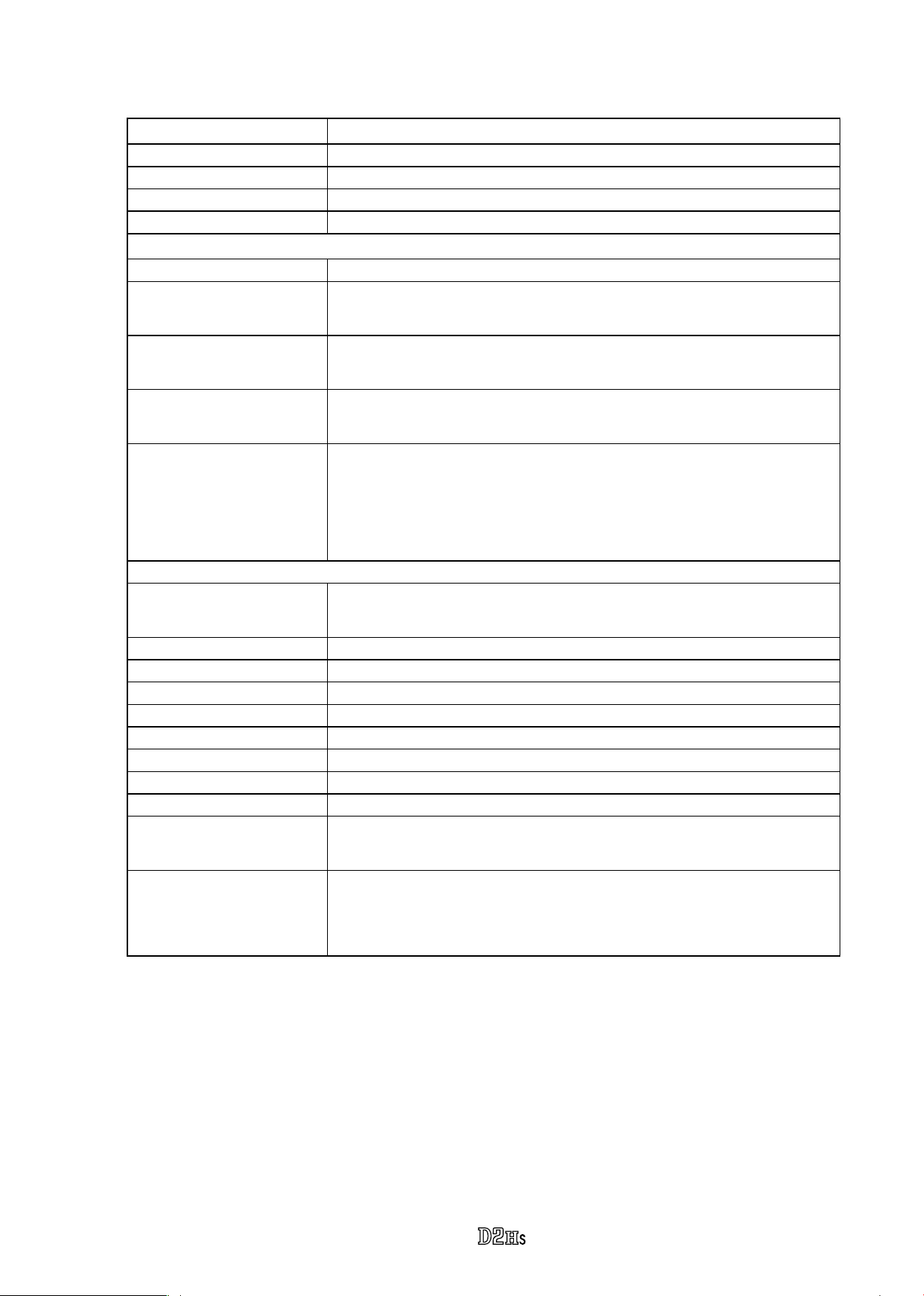
Type
Effective pixels 4.1 million
Image sensor 23.3 × 15.5 mm; total pixels: 4.26 million
Image size (pixels) 2464 × 1632 (large), 1840 × 1224 (medium)
Lens mount Nikon F mount (with AF coupling and AF contacts)
Single-lens reex digital camera with interchangeable lenses
Compatible lenses*
Type G or D AF Nikkor All functions supported
Micro Nikkor 85 mm
F2.8D
Other AF Nikkor † All functions supported except 3D color matrix metering and 3D
AI-P Nikkor All functions supported except 3D color matrix metering, 3D
Non-CPU Can be used in exposure modes A and M; electronic range nder can
* IX Nikkor lenses can not be used † Excluding lenses for F3AF
Picture angle Equivalent in 35-mm format is approximately 1.5 times lens focal
All functions supported except autofocus and some exposure modes
multi-sensor balanced ll-ash for digital SLR
multi-sensor balanced ll-ash for digital SLR, and autofocus
be used if maximum aperture is f/5.6 or faster;color matrix metering,
multi-sensor balanced ll-ash for digital SLR, and aperture value
display supported if user provides lens data
length
Viewnder Optical xed eye-level pentaprism
Diopter adjustment –3 – +1 m–1
Eyepoint 19.9 mm (–1.0 m–1)
Focusing screen Type B Brite View clear-matte Mark III screen provided
Fame coverage Approximately 100% of lens (vertical and horizontal)
Magnication Approximately 0.86× (50-mm lens at innity; –1.0 m–1)
Reex mirror Quick return
Lens aperture Instant return with depth-of-eld preview
Focus-area selection Single area or group can be selected from 11 focus areas
Lens servo Instant single-servo AF (S); continuous-servo AF (C); manual (M);
predictive focus tracking automatically activated according
to subject status in single- and continuous-servo AF
- M1 ・ -
VBA10601-R.3665.A
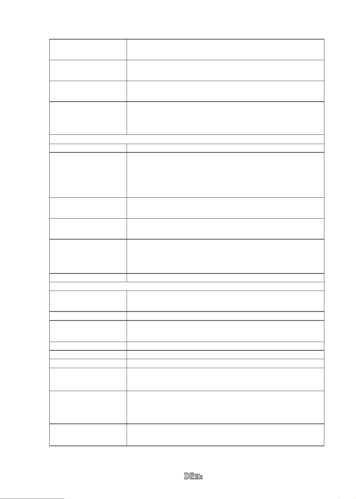
Autofocus TTL phase detection by Nikon Multi-CAM2000 autofocus module
Detection range
(ISO 100 at 20 °C / 68 °F)
–1 – +19 EV (0 – +19 EV for focus areas at left and right edges of
frame)
AF-area mode Single-area AF, dynamic-area AF, group dynamic-AF, dynamic-area
AF with closest subject priority
Focus lock Focus can be locked by pressing shutter-release button halfway
(single-servo AF) or by pressing AE-L/AF-L button
Exposure
Metering Three-mode through-the-lens (TTL) exposure metering
Matrix 3D color matrix metering supported with type G and D lenses;
color matrix metering available with other CPU lenses and with
non-CPU lenses if user provides lens data
Center-weighted Weight of 75% given to 6, 8, 10, or 13-mm circle in center of
frame, or weighting based on average of entire frame
Spot Meters 3-mm circle (about 2% of frame) centered on selected
focus area (on center focus area when non-CPU lens is used)
Range
(ISO 100 equivalent,
0 – 20 EV (3D color matrix or center-weighted metering)
2 – 20 EV (spot metering)
f/1.4 lens, 20 °C/68 °F)
Exposure meter coupling Combined CPU and AI
Exposure control
Exposure modes Programmed auto with exible program; shutter-priority auto;
aperture priority auto; manual
Exposure compensation
–5 – +5 EV in increments of 1/3, , or 1 EV
Bracketing Exposure and / or ash bracketing (2–9 exposures in increments
of 1/3, , 2/3, or 1 EV)
Exposure lock Luminosity locked at detected value with AE-L/AF-L button
Shutter Electronically-controlled vertical-travel focal-plane shutter
Speed
Sensitivity
30 – 1/8000 s in steps of 1/3, , or 1 EV, bulb
200 – 1600 in steps of 1/3, , or 1 EV, 3200, 6400; auto gain to 1600
(ISO equivalent)
White balance Auto (TTL white-balance with main image sensor, 1,005 pixels
RGB sensor, and ambient light sensor), six manual modes with
ne-tuning, color temperature setting
Bracketing 2–9 exposures in increments of 1, 2, or 3
- M2 ・ -
VBA10601-R.3665.A
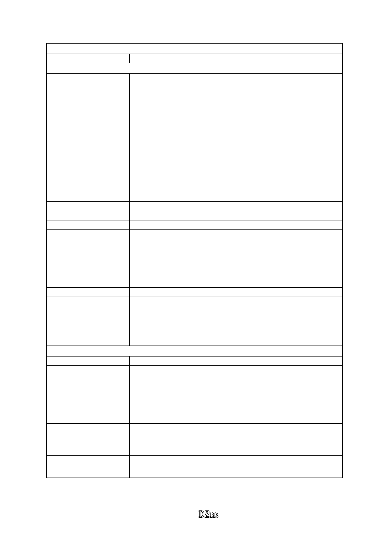
Flash
Sync contact X-contact only; ash synchronization at up to 50 s
Flash contrrol
TTL TTL ash control by combined ve-segment TTL multi sensor with
single-component IC and 1,005-pixel AE sensor
• SB-800, 600: i-TTL balanced ll-ash for digital SLR and
standard i-TTL ash for digital SLR
• SB-80DX, 28DX, or 50DX with type G or D lens: 3D multi-sensor
balanced-ll ash for digital SLR
• SB-80DX, 28DX, or 50DX with other lens: multi-sensor balanced-
ll ash for digital SLR
• SB-80DX, 28DX, or 50DX with spot metering: standard TTL ash
for digital SLR
Auto aperture Available with SB-800, 80DX, or 28DX and CPU lens
Non-TTL auto Available with such Speedlights as SB-800, 28, 27, and 22s
Range-priority manual Available with SB-800
Sync modes Front curtain sync (normal), slow sync, rear-curtain sync, redeye
reduction, red-eye reduction with slow sync
Flash-ready indicator Lights when SB-series Speedlight such as 800, 600, 80DX,
28DX, 50DX, 28, 27, or 22s is fully charged; blinks for 3 s
after ash is red at full output
Accessory shoe Standard ISO hot-shoe contact with safety lock
Creative Lighting
System
With SB-800 and 600, supports Advanced Wireless Lighting
(SB-600 only supports AWL when used as remote ash), Auto
FP High-Speed Sync, Flash Color Information Communication,
modeling illumination, and FV Lock
Storage
Media Type I and II CompactFlash memory cards; Microdrives
File system Compliant with Design Rule for Camera File System (DCF) and
Digital Print Order Format (DPOF)
Compression • Compressed 12-bit NEF (RAW): approximately 50–60%
• JPEG: JPEG baseline-compliant, can be selected from Fixed size
and Optimal quality
Self-timer Electronically controlled timer with 2 – 20s duration
Depth-of-eld preview Lens aperture stopped down when depth-of- eld preview button is
pressed
Monitor 2.5
brightness adjustment
″ ,
232,000-dot, low-temperature polysilicon TFT LCD with
- M3 ・ -
VBA10601-R.3665.A
Video output Can be selected from NTSC and PAL
External interface USB 2.0
Tripod socket ″ (ISO)
Firmware User upgradeable
Supported languages Chinese (Simplied), Dutch, English, French, German, Italian,
Japanese, Korean, Spanish, Swedish
Power source • One 11.1V EN-EL4 rechargeable Li-ion battery
• EH-6 AC adapter (available separately)
Dimensions (W × H × D) Approximately 157.5 × 149.5 × 85.5 mm (6.2″ × 5.9″ × 3.4″)
Weight Approximately 1070 g (2 lb 6 oz) without battery, memory card,
body cap, or monitor cover
Operating environment
Temperature 0 – 40 °C (32 – 104 °F)
Humidity Less than 85% (no condensation)
• Unless otherwise stated, all gures are for a camera with a fully-charged batteryoperating at an
ambient temperature of 20 °C (68 °F).
• Nikon reserves the right to change the specications of the hardware and software described in this
manual at any time and without prior notice. Nikon will not be held liable for damages that may
result from any mistakes that this manual may contain.
- M4 ・ -
Precautions for disassembly/(re)assembly
VBA10601-R.3665.A
Notes
: ①
②
③
④
⑤
⑥
⑦ All wires are special parts (supporting UL), so be sure to use specied wires.
Points to notice for Lead-free solder products
・Lead-free solder is used for this product.
・For soldering work, the special solder and soldering iron are required.
・Do NOT mix up lead-free solder with traditional solder.
・Use the special soldering iron respectively for lead-free solder and lead solder. They
In disassembly/(re)assembly, be sure to use conductive mat (J5033) and wrist strap (J5033-5), in order to
protect electric parts from static electricity.
Before disassmbling, be sure to remove batteries, AC power cord, and battery for clock (CR1616).
In disassembling, be sure to memorize the processing state of wires and FPC, screws to be xed and their
types, etc.
The low-pass lter of the image PCB is easily damaged. Handle it very carefully.
In the chapter of Disassembly, sometimes a large assembly unit is removed. In case such a unit is further
disassembled , refer to the exploded technical drawings.
In Disassembly/(re)assembly chapters, the dip-proof sponge is not mentined. In case parts are replaced, be
sure to attach the dip-proof sponge by referring to the exploded technical drawings.
cannot be used in common.
Disassembly
1. External units and Imaging-related PCBs
Note 1: Before disassembling a camera, of which the main FPC should be replaced, be sure to read and note down the
adjustment value of the environment light sensor by adjustment software for the camera unit.
read out from the camera, replace the top cover unit, too. (Refer to Page A28 for the details when replaced.)
Note 2: When "Seprating Front and Rear bodies", "Disassembling Image PCB", and "Disassembling Bayonet", be sure to perform
"Reset of AF defocus compensation amount" by D2Hs adjustment software after reassembly.
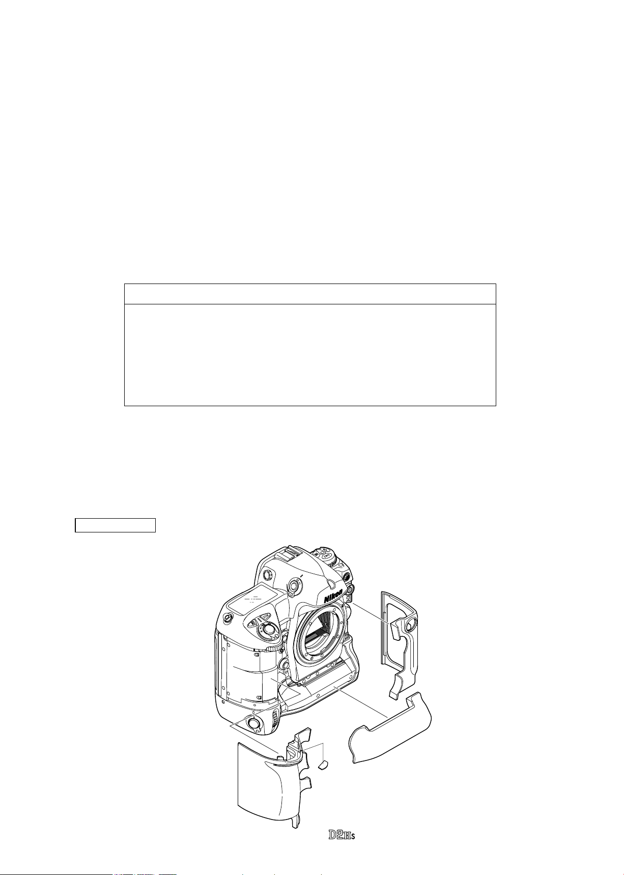
External rubber
Remove the grip rubber (#B60-1), apron lower rubber (#B66), and rubber at the lm rewind side (#B61).
・
#B61
If the value cannot be
#729
#B60-1
- D1 ・ -
#B66
I/F Block
Take out 3 screws (#1589) and detach the I/F block.
・
VBA10601-R.3665.A
#1589×3
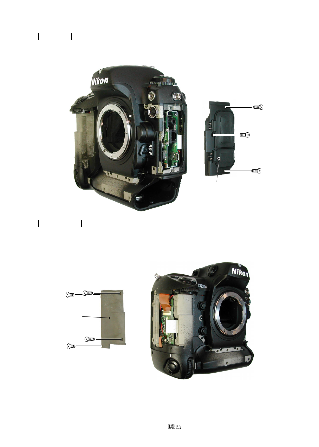
Grip Cover
Take out 2 screws (#1534) and 2 screws (#1510) to detach the grip cover.
・
#1534×2
Grip cover
#1510×2
I/F Block
- D2 ・ -
VBA10601-R.3665.A
- D3 ・ -
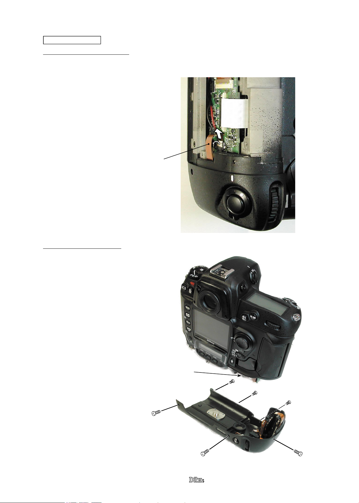
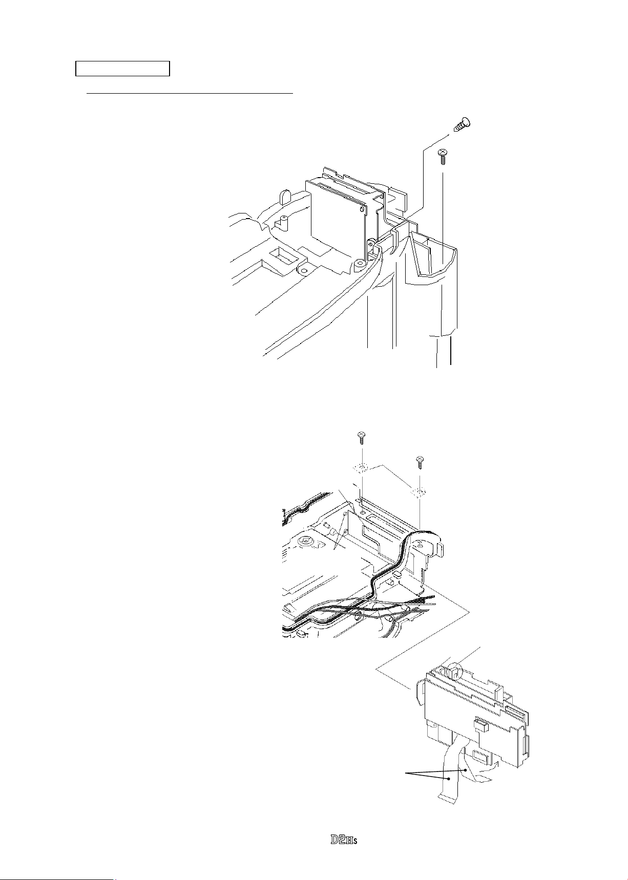
1. Remove Vertically position FPC
Bottom Cover Unit
2. Remove Bottom cover unit
Vertically position FPC
Bottom cover unit
・
Remove the vertically position FPC from
the connector.
・
Take out 3 screws (#1512) and 3 screws
(#1517).
・
Remove the bottom cover unit from the
camera body.
#1512×3
#1517×3
Note: Between the bottom cover and
the body (i.e. A part), there is the
washer (T=0.3) inserted.
When assembling, be sure to put
it back into the original position.
(This measure is for lling in a
gap between the back door and
bottom cover.)
A part
VBA10601-R.3665.A
- D4 ・ -
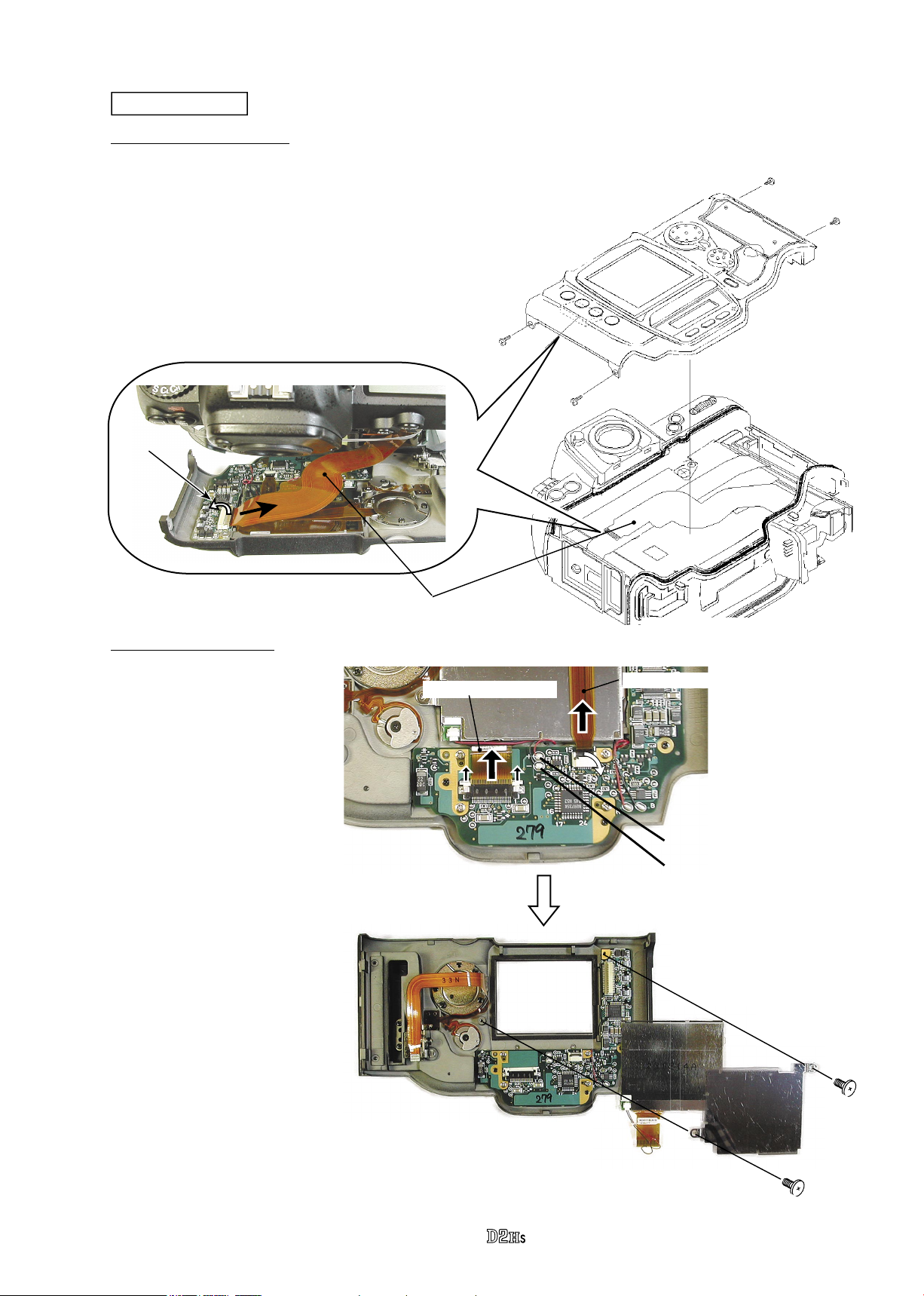
Back door unit
1. Remove Back door unit
2. Remove TFT Monitor
・
Take out 4 screws (#1514) and detach the
back door unit slowly.
・
Remove the TFT (Memory compression PCB
connection-FPC: #5041) from the connector.
(ref. Fig.1
)
Fig.1
#5041
Connector
#1514×4
Back door unit
・
Remove the red and black
wires of the TFT back light
harness.
・
Remove the TFT monitor
FPC and AF area FPC from
the connector.
・
Take out 2 screws (#436)
and remove the TFT
retaining (#432) and TFT
monitor (#5043).
#436×2
#432
#5043
Red: TFT back light
Black: TFT back light
TFT monitor FPC
AF area FPC
3. TFT-PCB, Speaker, Microphone, other small parts
�
�
VBA10601-R.3665.A
#B428
#1522×2
#1513×2
#437
#425
#453
#427
#442
#445
#460
#467
Microphone
TFT PCB
#463
Speaker
#1560×2
#1508×3
#456
#B439
#1531×2
TFT & Memory compression PCB connection-FPC
Remove the TFT & Memory compression PCB connection-FPC (#5041) from the connector.
・
#5041
- D5 ・ -
Connector
Battery contacts unit
1. Remove wires
Remove the red and black wires that connect from
・
the battery contacts.
VBA10601-R.3665.A
Black : Battery contact
Red : Battery contact
2. Remove Battery contacts and Battery case upper unit
Remove the battery contacts connection-FPC from the connector.
・
Take out 2 screws (#1515) and 1 screw (#812) and detach the battery contact unit (#B801).
・
Take out 1 screw (#1520) and remove the battery case upper unit (#B823), (which is attached by the
・
both-sided adhesive tape).
#812
#1515×2
Battery contacts connection FPC
#B801
Connector
#1520
#B823
- D6 ・ -
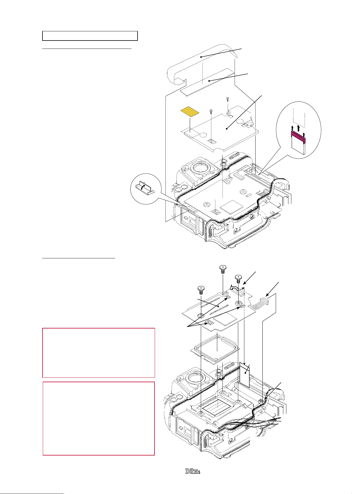
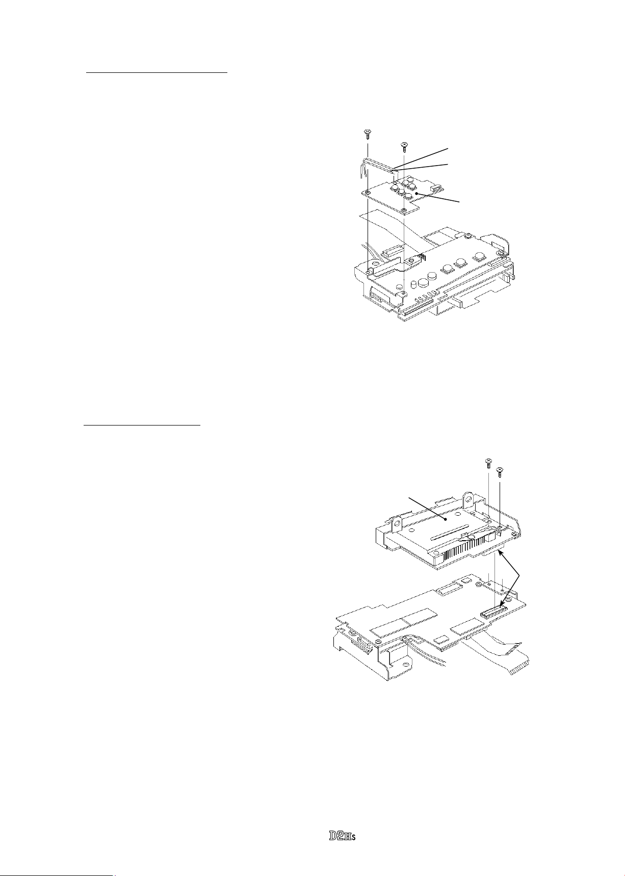
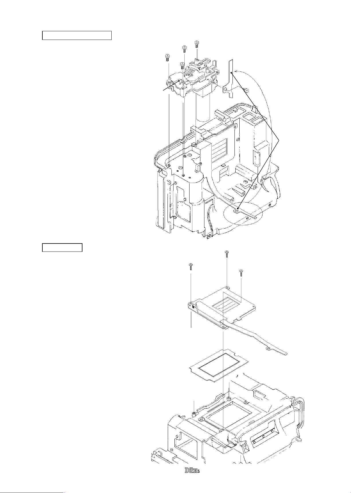
Imaging (LBCAST) PCB unit
VBA10601-R.3665.A
1. Remove Image PCB cover plate
Detach the both ends of the connection-
・
FPC of the memory compression
PCB & USB PCB (#5040) from the
connector.
(The EMI (electromagnetic interference)
prevention sheet (#592) is attached on
the connection-FPC.
Take out 2 screws (#1530).
・
Remove the image PCB cover plate.
・
)
#596
#5040
#592
Image PCB cover plate
#1530×2
2. Remove Image PCB unit
Remove the connection-FPC of the
・
image PCB & memory compression
PCB (#5038) from the connector.
Remove the image PCB harness
・
from the connector.
Take out 3 screws (#525).
・
Remove the image PCB unit.
・
Remove the screen frame (#529).
・
Note 1: For some bodies, the washer
is already put on the attaching face of
the image PCB. There is an indication
of the mark in red with magic marker.
Refer to Page A25 in the Assembly chapter
for the details.
*Note 2: For some bodies, there are L-shaped
washers attached at 3 parts of A-part on the
image-PCB.
On such PCB, there is red-marked indication
on its attachment side, so if the washers
come off, reattach them.
In case the PCB is replaced with the one
without red marking, the washers are NOT
necessary.
Image PCB unit
*A part
#529
#525×3
Connector
Image PCB harness
#5038
Connector
- D7 ・ -

Top cover unit
1. Remove Top cover FPC connection and EL wires
Remove the red and black wires
・
on the main PCB.
Remove the top cover FPC from
・
the connector.
VBA10601-R.3665.A
Top cover FPC
Red: Back light for top LCD (EL)
Black: Back light for top LCD (EL)
2. Remove Top cover unit
Remove the eyepiece diopter knob cover
・
(#1130). Then take out the screw (#1568)
to remove the eyepiece diopter knob
(#1121).
Take out 8 screws in total (1 screw:#1543,
・
2 screws:#1537, 1 screw: #1519, 1
screw:#1510, 2 screws:#1516, and 1
screw: #1556).
#1537×2
#1130
#1543
#1568
#1121
#B1137
Top cover (#B23)
#1519
#1510
Detach the top cover (#B23) then the
・
eyepiece block unit (#B1171) comes off.
#1516×2
#1556
- D8 ・ -
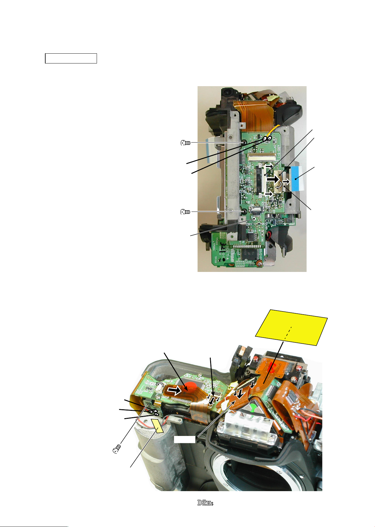
2. Separate Front and Rear bodies
Main FPC 1 unit
Remove the red and black wires on the main
・
FPC 1 side face.
Remove the connection-FPC of the main
・
FPC1 & DC/DC unit 2 (#5033) from the
connector.
Remove the connection-FPC of the main
・
FPC1 & memory compression PCB (#5035)
from the connector.
Take out 2 screws (#1532).
・
#1532×2
VBA10601-R.3665.A
Connector
Connector
Yellow: Charge motor
Black: Charge motor
Main FPC 1 unit
Remove the 3 wires (in red, brown and black) that connect from the charge SW.
・
Remove the P - F (Preview & function) FPC (#5027) from the connector.
・
Remove the shutter FPC (#5014) from the connector.
・
Remove the penta FPC (#B15005) from the connector.
・
Unscrew #1553.
・
#5033
#5035
#684
Brown: Charge SW
Red: Charge SW
Black: Charge SW
#1553
TA-0005
(6×12)
#5027
#B15005
- D9 ・ -
#5014
Remove the connecting connectors of
・
the main FPC 1 and main FPC 2.
Take out 3 screws (#1566) to detach
・
the main FPC 1.
Main FPC 2
VBA10601-R.3665.A
#1566×3
Main FPC 1
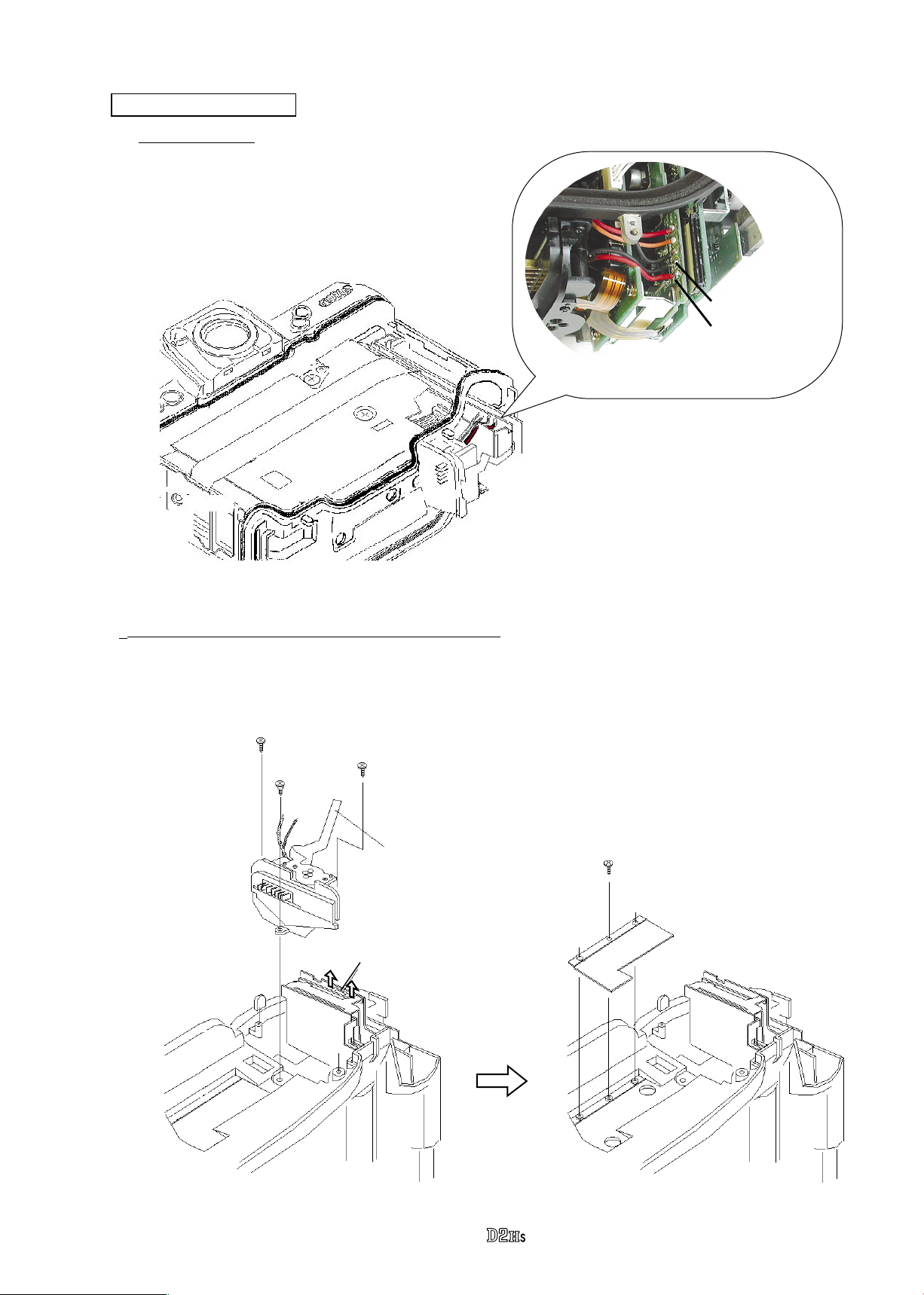
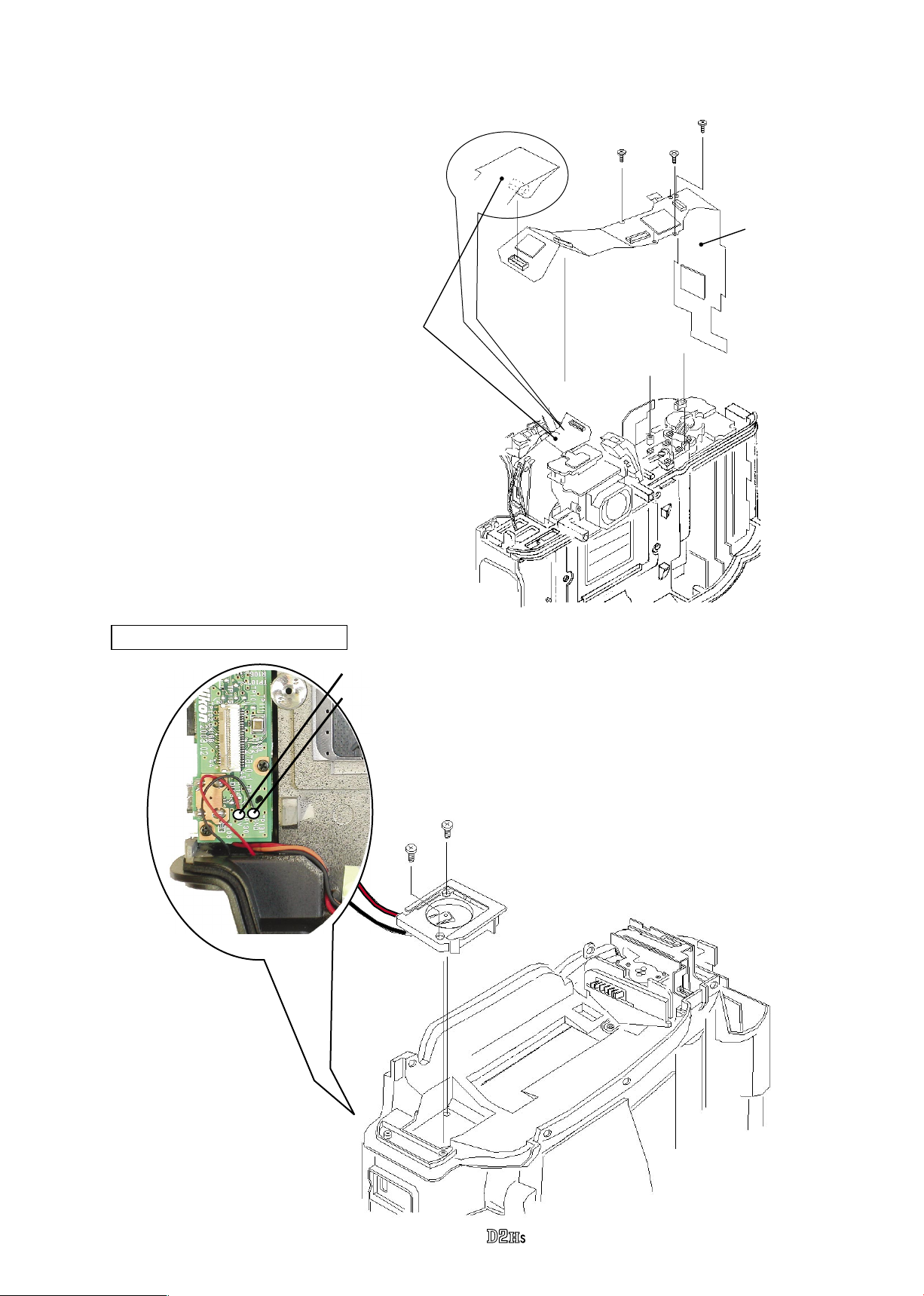
Back-up Battery Box Unit
Red: Back-up battery box
Black: Back-up battery box
#1533×2
#B818
Remove the red and black wires on the
・
USB PCB.
Take out 2 screws (#1533) and remove the
・
back-up battery box unit (#B818).
- D10 ・ -
Separate Front and Rear bodies
Remove the black and orange
・
wires that connect from the I/F
PCB.
Black: I/F PCB
Orange: I/F PCB
VBA10601-R.3665.A
#1590×2
#1535
#1514×6
Take out 2 screws (#1590) under the
・
eyepiece.
Unscrew #1535.
・
Take out 6 screws (#1514).
・
Separate the front body from the rear
・
body.
- D11 ・ -
VBA10601-R.3665.A
- D12 ・ -
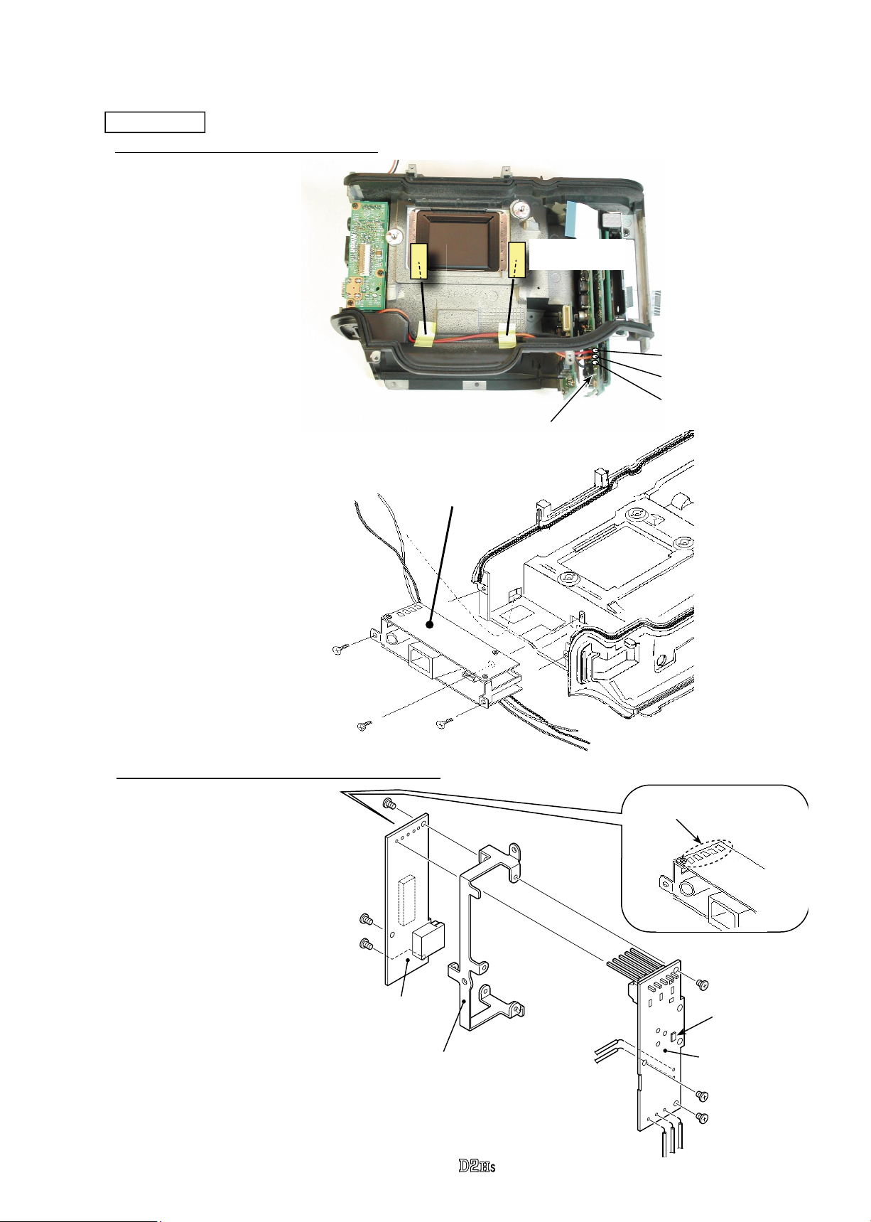
3. Rear Body
I/F PCB unit
Red: I/F PCB
Orange: I/F PCB
Black: I/F PCB
・
Remove the 3 wires (in red,
orange and black) from the
DC/DC unit 2.
・
Remove 2 pieces of the tape
TA-0005(20×10).
2. Separation into DC-IN video PCB and USB PCB
1. Remove I/F PCB unit from Rear body
・
Take out 2 screws (#1510
and #1523) to remove
the I/F PCB unit from
the rear body.
#1510
#1523×2
I/F PCB unit
・
Remove 5 soldering
bridges.
・
Take out 3 screws (#1526)
to remove the USB PCB
from the IF-PCB locking
plate.
・
Take out 3 screws (#1526)
to the DC-IN video PCB
from the IF-PCB locking
plate.
Soldering bridge×5
DC-IN video PCB
IF-PCB locking plate
USB PCB
#1526×3
#1526×3
TA-0005
(20×10)×2
*FU1
* Fuse-FU1 is replaceable before separating
the DC-IN video PCB from the USB-PCB.
Phenomenon when fuse-FU1 is blown out:
In case of using DC-IN as power, the power
does NOT turn ON.
DC/DC unit 2
CF card PCB unit
1. Remove CF card PCB unit from Rear body
Take out 2 screws (#1531).
・
VBA10601-R.3665.A
#1531×2
Take out 2 screws (#1531).
・
Hold down 2 connection-FPCs
・
with ngers so that they are not
hooked to the rear body, then
remove the CF card PCB unit
from the lower holes of the rear
body.
#1531×2
CF card eject lever
CF card PCB unit
2 connection-FPCs
- D13 ・ -
2. Remove DC/DC PCB unit 1
Remove the red and black wires.
・
Take out 2 screws (#1530) to remove the
・
DC/DC PCB unit 1.
VBA10601-R.3665.A
#1530×2
Black: DC/DC PCB unit 2
Red: DC/DC PCB unit 2
DC/DC PCB unit 1
3. Remove CF Card PCB
Take out 2 screws (#1530).
・
Disconnect the connectors to remove the CF
・
card PCB.
#1530×2
CF card PCB
Connector
- D14 ・ -
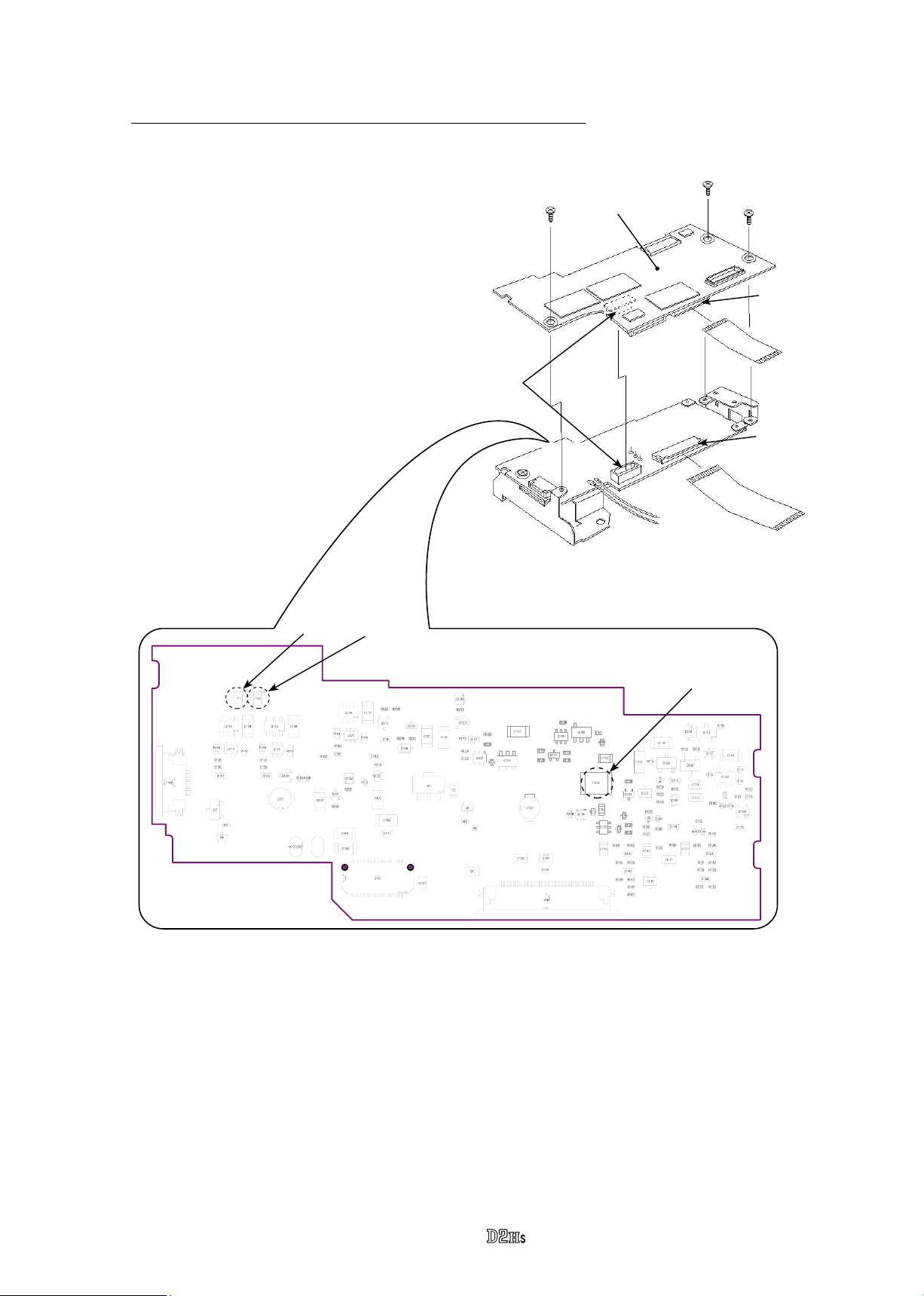
4. Separation of Memory compression PCB and DC/DC PCB unit 2
Take out 3 screws (#1530).
・
Me mory com pres sion
PCB
VBA10601-R.3665.A
#1530×3
Connector
①
Disconnect the connectors to separate
・
the memory compression PCB and
DC/DC PCB unit 2.
F1
F102
Connectors
DC/DC PCB unit 2
F104
#5035
Connector
#5033
②
*If the memory compression PCB is separated from DC/DC unit 2, the following fuses (except F104 Polyswitch) can be
replaced.
・Phenomenon when fuse or *Polyswitch burns out.
F1: Both battery and DC-IN cannot be turned ON.
F102: Because there is no power except VBAT and VBT6, the LCD keeps the indications just before burnout of fuses,
and also other functions of camera cannot work.
*F104: Because there is no output from VCC12 and VCC23, the backlight of TFT cannot light up and TFT shows
indications but they can hardly be veried. At the same time, the control panel on top of the camera keeps the
indications just before burnout of fuses.
As for F104 (Polyswitch), however, if turning the main switch of camera to OFF for a few seconds and then turning
to ON, or if removing the battery once and then inserting it again, this Polyswitch recovers its function. So it does
not usually burn out (break) permanently, compared with other fuses.
- D15 ・ -
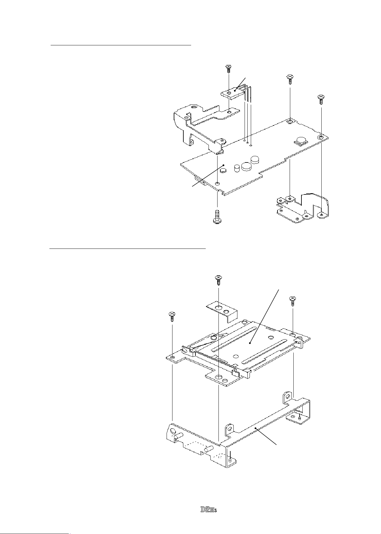
5. Remove Locking plate from DC/DC PCB unit 2
VBA10601-R.3665.A
#1540
#1530×2
#5086
Take out the screws (#1530 and
・
Locking plate
(#70)
#1540) to remove the locking
plate of the DC/DC unit 1 & 2
(#70).
Take out 2 screws (#1530) to
・
remove the locking plate of the
memory compression PCB &
DC/DC PCB unit 2 (#69).
Remove the solder of 3 legs of
・
the power transistor (#5086) to
detach it.
DC/DC unit 2
6. Remove CF locking plate unit from CF card PCB unit
#1530
Locking plate
(#69)
#1530×3
Take out 3 screws (#1530) to
・
detach the CF knob cover (#449)
and the CF locking plate unit.
CF card PCB unit
#449
CF locking plate unit
- D16 ・ -
SQ (Sequence) PCB unit
VBA10601-R.3665.A
#1538×4
Unscrew #683 to remove the
・
shutter FPC from the SQ
PCB.
Take out 4 screws (#1538).
・
Remove the SQ PCB unit
・
from the rear body.
Shutter unit
SQ PCB unit
#683
Shutter FPC
#1704×3
Take out 3 screws (#1704) to
・
detach the shutter unit.
Note)The dust-proof sheet (#540)
is attached on the rear body
with the both-sided adhesive
tape.
Shutter unit
#540
- D17 ・ -
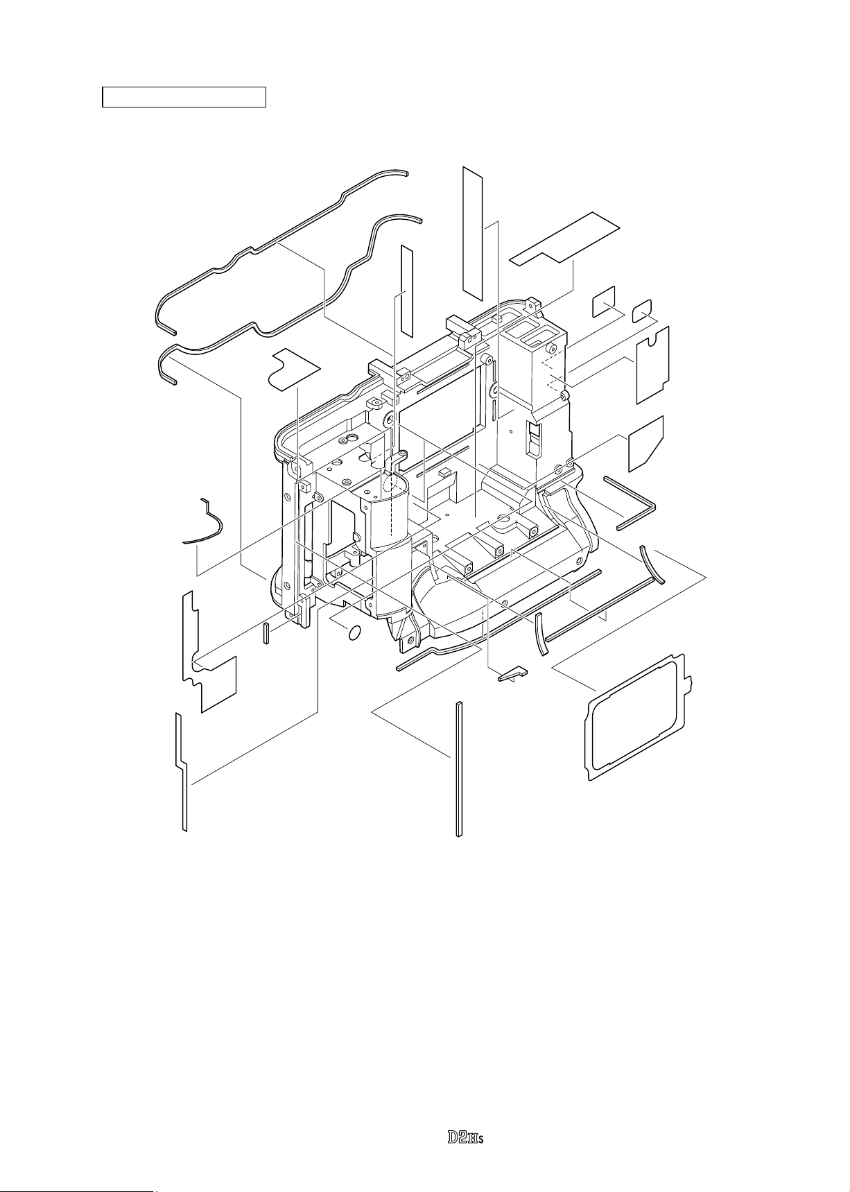
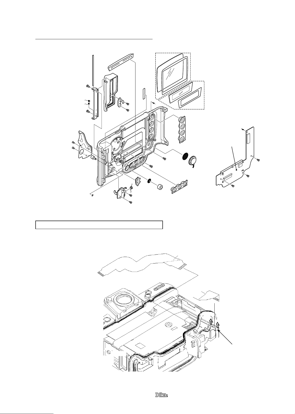
Rear body small parts
VBA10601-R.3665.A
#575
#566
#574
#571
#271
#567
#568
#573
#577-1
#576
#398
#397
#399
#572
#565
#564
#563
#569
#561
#595
#554
#562
#533
- D18 ・ -
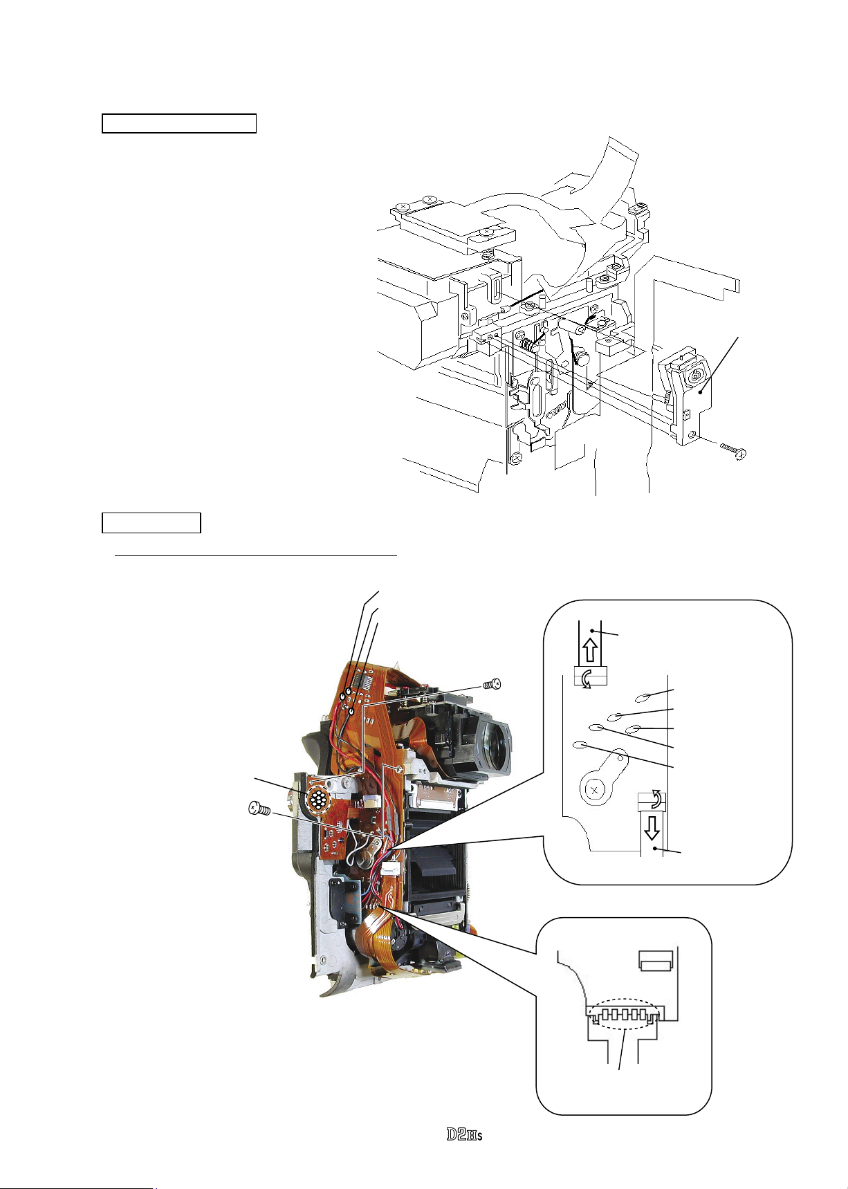
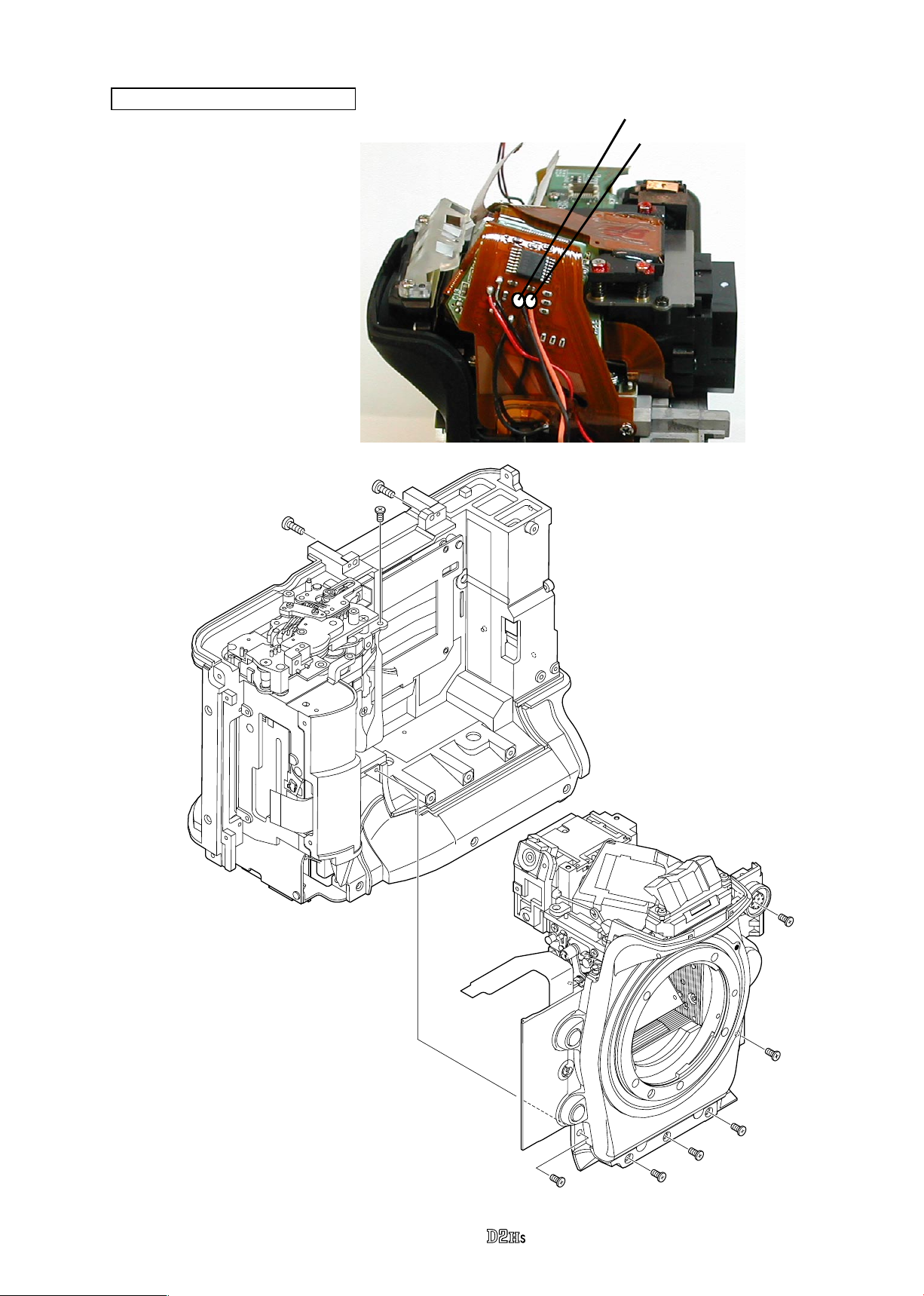
4. Front Body
Adjustable diopter unit
Unscrew #1535 to detach the
・
adjustable diopter unit.
VBA10601-R.3665.A
Adjustable
dioptor unit
#1535
Main FPC 2
1. Remove wires, FPCs and soldering bridges
Remove the red and black wires
・
that connect from the AF motor
and the black wire that connects
from the lens contact FPC.
Remove the grey and black wires
・
that connect from the lens release
SW, and also remove the red, blue
and brown wires that connect
from SCM change-over.
Soldering bridges of 10
pin connectors
#1530
Red: AF motor
Black: AF motor
Black: Lens contact FPC
#1503
Lens contact FPC
Red: SCM change-over
Blue:
〃 〃
Brown:
Gray: Lens release SW
Black:
TTL FPC
〃 〃
〃 〃
Remove the soldering bridges
・
of 10 pin connectors.
Remove the lens contact
・
FPC and TTL FPC from the
connector.
Remove 5 soldering bridges
・
of AF-PI FPC.
Take out the screws (#1503
・
and #1530).
5 soldering bridges of AF-PI
FPC.
- D19 ・ -
VBA10601-R.3665.A
2. Remove Main FPC 2
Remove the screw (#283), press-contact plate (#282) and press-contact rubber (#285) to remove the main
・
FPC 2 from the front body.
#283
#282 #285
Main FPC 2
Prism Box
1. Separate Prism box unit from Front body
When the prism box is detached from
*
the front body, be sure to make the
inspection and adjustment of parallax
on Page A48.
#1188×4
Take out 4 screws (#1188).
・
Remove the prism box unit,
・
then the washers for alignment
& adjustment (#1180 and
#1181) come off.
#1180
#1181
- D20 ・ -
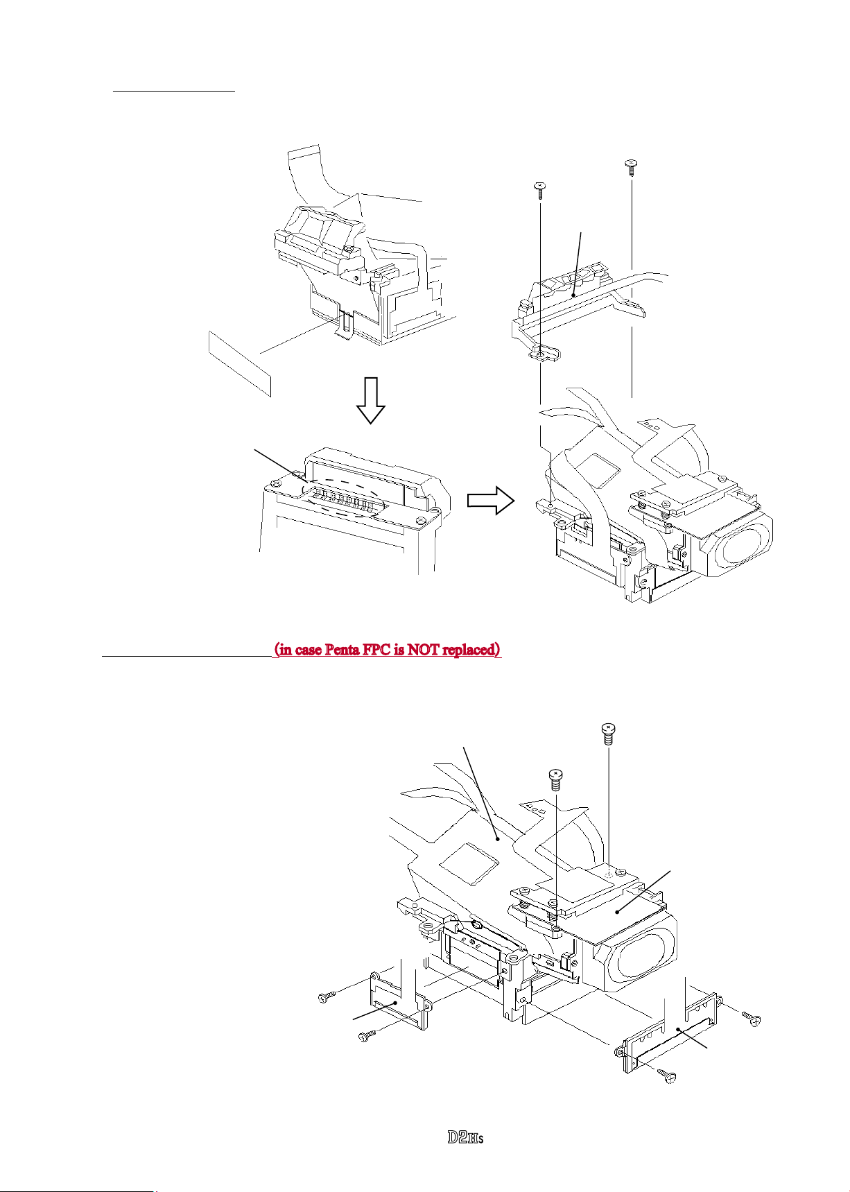
2. Remove S. I unit
Remove the penta
①
dust-proof tape
(#1205).
#1205
Remove 8 soldering bridges
②
of the penta FPC.
VBA10601-R.3665.A
Take out 2 screws (#1577) to detach the
③
S. I. unit.
#1577×2
S. I. unit
3. Remove Penta FPC unit (in case Penta FPC is NOT replaced
Take out 2 screws (#1551) to
・
detach the right-display LCD
unit.
Take out 2 screws (#1551)
・
Penta FPC unit
to detach the bottom-display
LCD unit.
Take out 2 screws (#1565) to
・
detach the AE sensor holder
unit attached to the penta FPC.
Detach the penta FPC from the
・
penta, (which is attached with
the both-sided adhesive tape.)
Right-display LCD unit
#1551×2
)
#1565×2
AE sensor holder unit
Bottom - d i s p l a y
LCD unit
#1551×2
- D21 ・ -
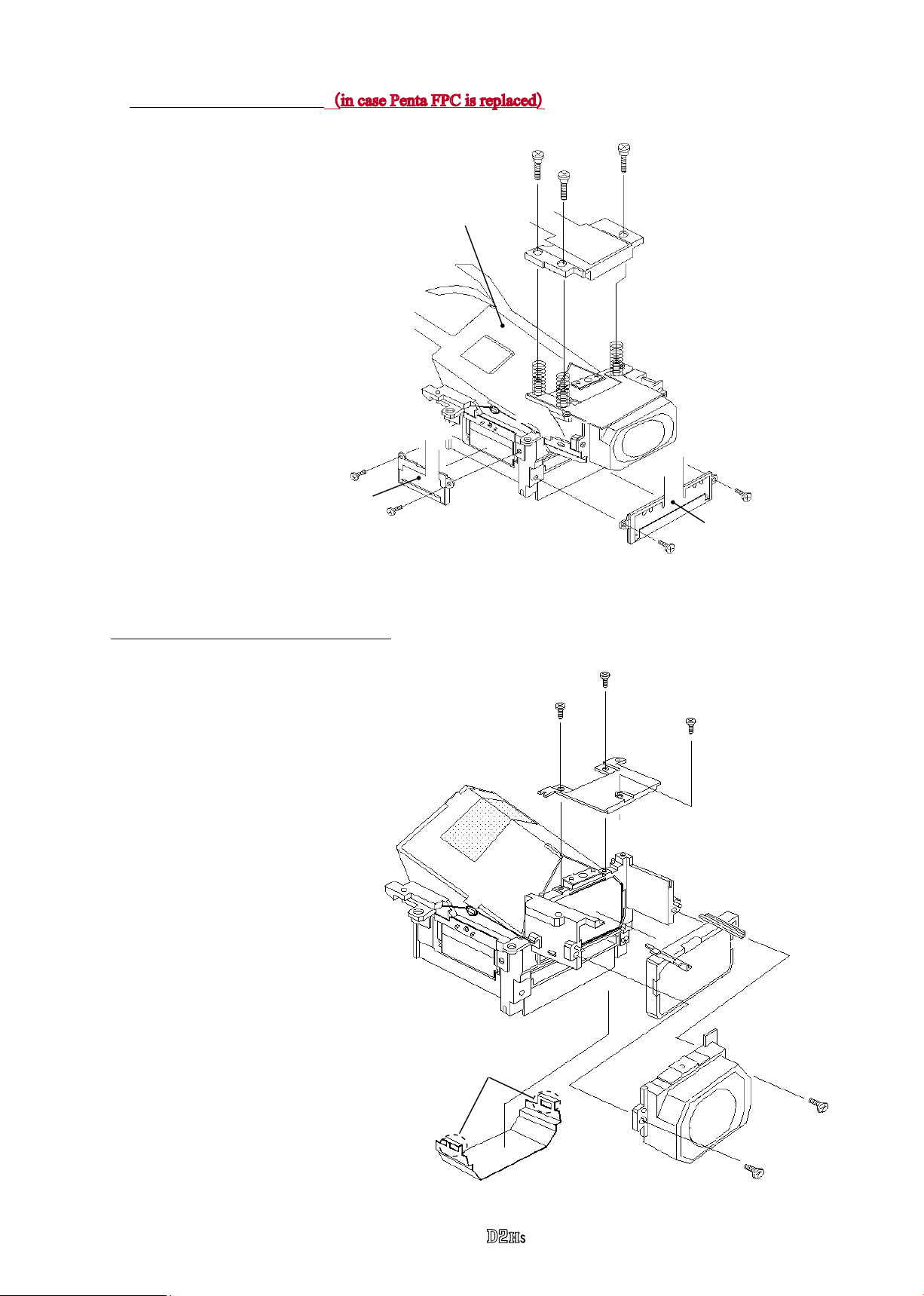
VBA10601-R.3665.A
3-1. Remove Penta FPC unit(in case Penta FPC is replaced
Take out 2 screws (#1551) to
・
detach the right-display LCD
unit.
Take out 2 screws (#1551) to
・
Penta FPC unit
detach the bottom-display LCE
unit.
Take out 3 screws (#1133) to
・
detach the AE sensor holder.
Remove 3 springs for AE
・
device adjustment (#1134).
Detach the penta FPC unit from
・
the penta, (which is attached
with the both-sided adhesive
tape.)
Right-display LCD unit
#1551×2
)
#1133×3
#1134×3
Bottom-display LCD unit
4. Remove Eyepiece holder unit C and B
Detach the 2 hooking parts of
・
the eyepiece cover (#1104) by
loosening them.
Take out 3 screws (#1544) to
・
detach the eyepiece top cover
(#1120).
Take out 2 screws (#1567) to
・
detach the eyepiece holder unit C
(#B1119).
Detach the eyepiece holder unit B
・
(#B1118).
#1551×2
#1544×3
#1120
#B1118
Hooking part×2
#1104
- D22 ・ -
#B1119
#1567×2
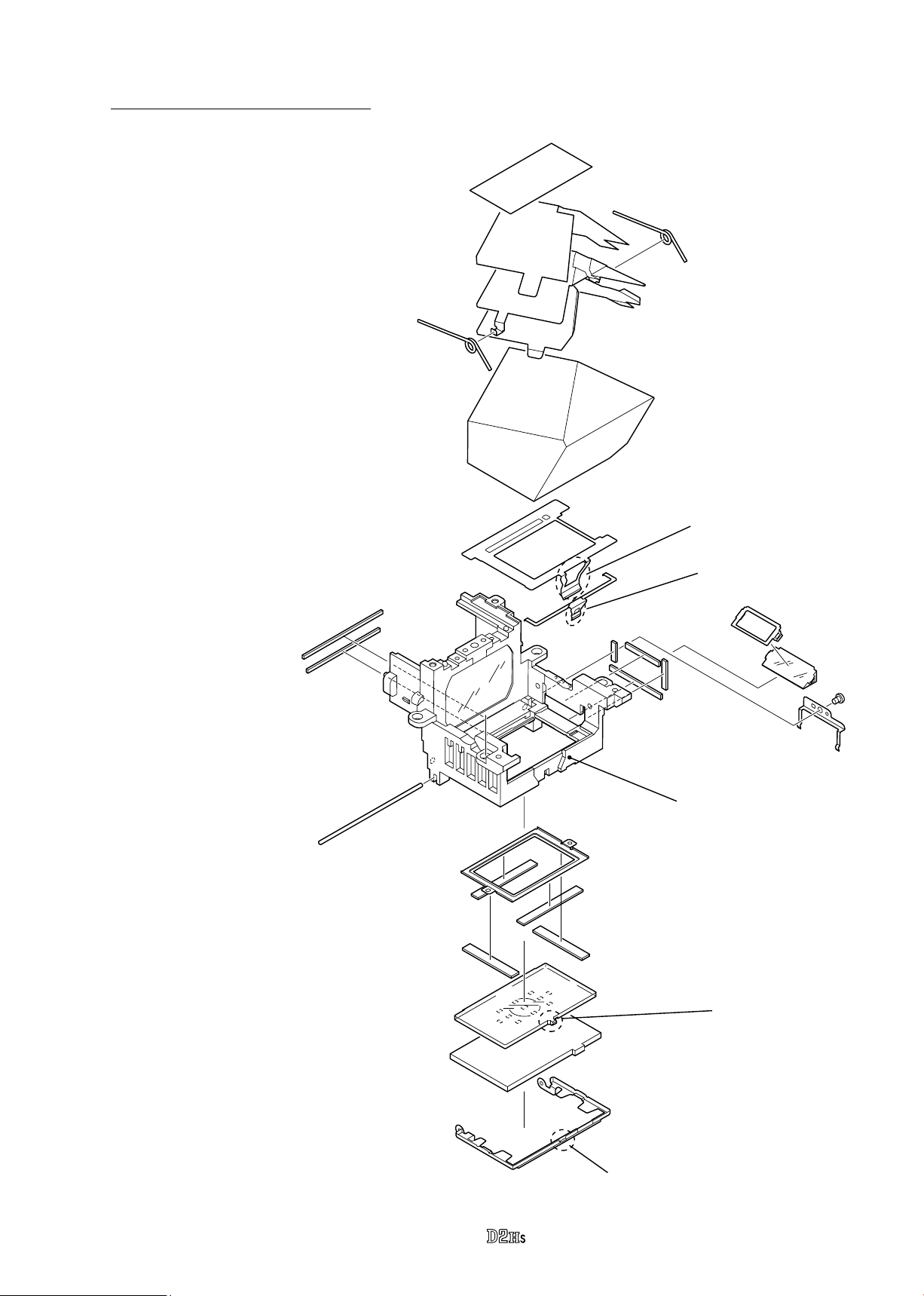
5. Screen, Prism, and other small parts
Unscrew #1562 to remove the retaining
・
spring (#1170).
Remove the right-display prism (#3012)
・
and the prism mask (#1166).
Remove the screen by unhooking the
・
convexity A of the screen frame from
the hooked part of the nder eld frame
A.
Remove the screen frame (#1102) by
・
detaching the supporting shaft for the
screen frame (#1103).
Remove the S. I. display plate by
・
unhooking the convexity A of the S.
I. display plate from the xed frame
(#1105).
#1114
#B1111
VBA10601-R.3665.A
Both-sided adhesive tape (#1194)
#1112×2
#1113
Prism
Finder eld
frame A
Hooked part of Finder
eld frame A
Remove 2 penta retaining springs
・
(#1112).
Remove the penta retaining plate
・
(#B1111) and penta insulating
sheet (#1114), (which are attached
in one with the both-sided adhesive
tape.)
Remove the penta retaining sheet
・
(#1113).
Remove the prism.
・
Remove the nder eld frame A.
・
Remove the xed frame (#1105).
・
Detach 2 sponges (#1199) and
・
remove the nder eld frame B.
#1196
#1197
#1103
#1105
#1193
Finder eld frame B
#1198×2
#1199×2
#1191
#1195
S. I. display plate
Screen
Screen frame
Hooked part of #1105
#1192
Prism box
Convexity B
#1166
#3012
#1562
#1170
- D23 ・ -
Convexity A
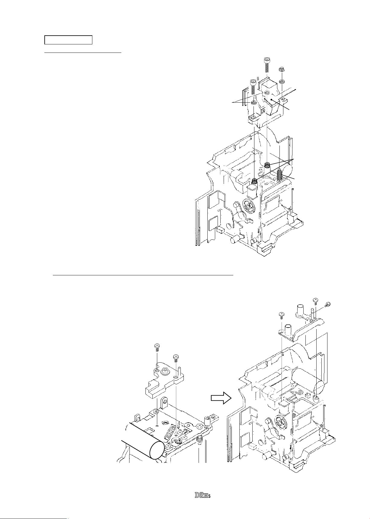
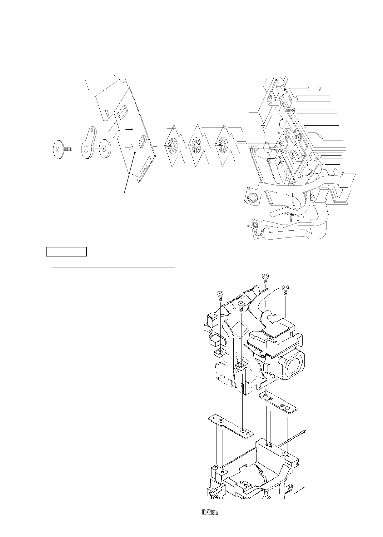
AF detector unit
1. Remove AF detector unit
VBA10601-R.3665.A
#295×2
Detach the E ring (#298) to remove the
・
washer (#294).
By using the Hexagonal wrench (φ1.5mm),
・
take out 2 screws (#295) and 2 washers
(#300).
Remove the AF detector unit.
・
Remove one spring (#293) and 2 springs
・
(#296).
* Even in case the AF detector unit is
not replaced, by going to the below 2
instruction without removing the above E
ring and 2 screws, it is possible to remove
the AF detector unit attached to the AF
detector installing plate.
#298
#294
#300×2
AF detector unit
#296×2
#293
2. Remove Press-contact base plate and AF detector installing plate
Take out 2 screws (#1530) to remove
・
the press-contact base plate (#281).
Take out one screw (#1523) and 2
・
screws (#1588) to remove the AF
detector installing plate (#B297).
#1530×2
#281
#1588×2
#1523
#B297
- D24 ・ -
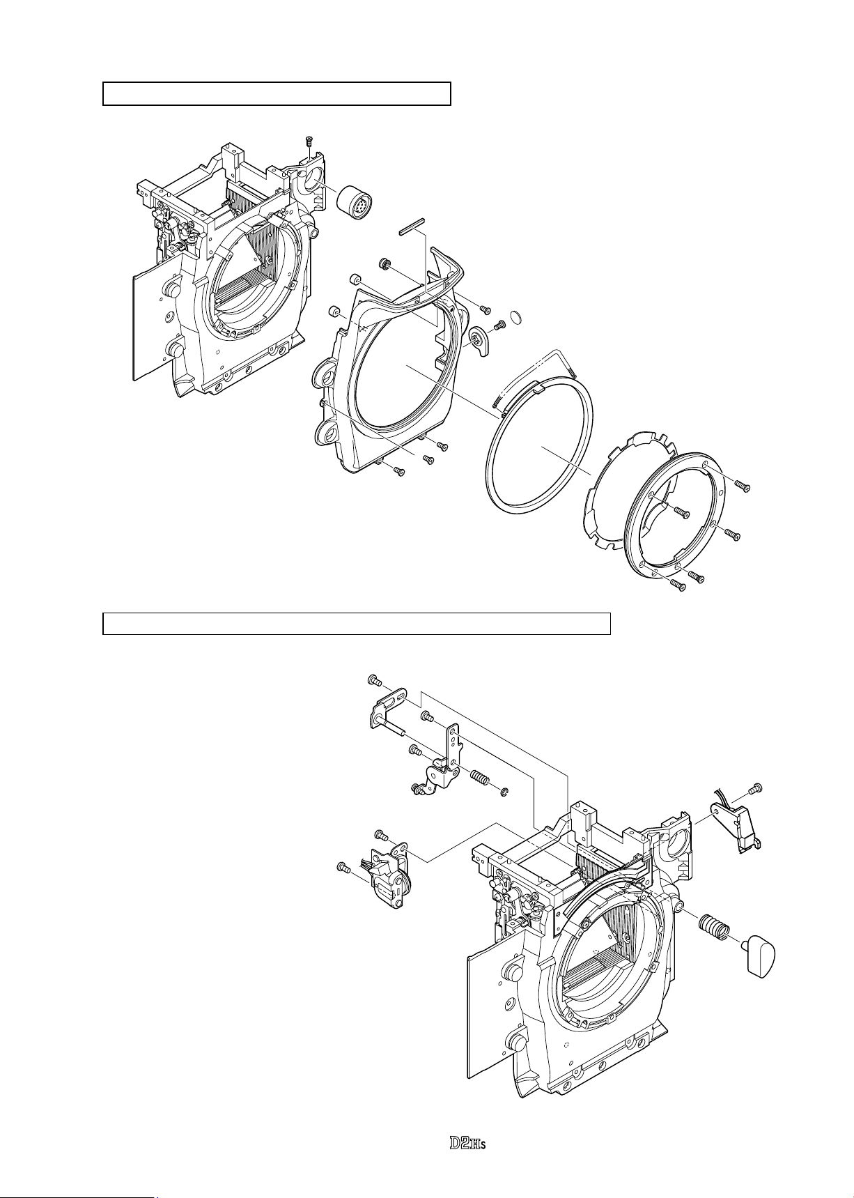
Bayonet mount, Apron, Remote connector (10 pins)
#47
#41
#555
VBA10601-R.3665.A
#410×2
#B22
#407
#1508×4
#387
#383
#B388
#406
Lens release SW unit, SCM change unit, Lens release button, Vertical lever unit
#B404
#402
#401
#1572×4
#1573
Unscrew #1532 to remove
・
the lens release SW unit
(#B378).
Take out 2 screws (#1508) to
・
remove the SCM change unit
(#B10384).
Unscrew (#379) to remove
・
the lens release button
(#376) and spring (#380).
Take out 2 screws (#1512) to
・
remove the vertical lever unit
(#B356).
#B371
#379
#1512×2
#1508×2
#B10384
#B356
#1532
#374
#1604
#B378
#380
#376
- D25 ・ -
 Loading...