

Nikon D200 Repair Manual
作成承認印 配布許可印
VBA13001-R.3677.A
VBA13001
Copyrighc2005 by Nikon Corporation.
All Rights Reserved.
無断転載を禁ず
!!
Printed in Japan November 2005
Recycled paper
再生紙を使用しています
REPAIR MANUAL
M
サービス
計画課

VBA13001-R.3677..A
- M1 ・ -
Specications
Type Single-lens reex digital camera with interchangeable lenses
Effective pixels 10.2 million
LBCAST image sensor 23.6× 15.8 mm; total pixels: 10.92 million
Image size (pixels) 3872× 2592 (L), 2896× 1944 (M), 1936× 1296 (S)
Lens mount Nikon F mount (with AF coupling and AF contacts)
Compatible lenses
Type G or D AF Nikkor All functions supported (except IX Nikkor)
Micro Nikkor 85 mm F2.8D All functions supported except autofocus and some exposure modes
Other AF Nikkor All functions supported except 3D color matrix metering Ⅱ and 3D multi-sensor
balanced ll-ash for digital SLR
AI-P Nikkor All functions supported except 3D color matrix metering Ⅱ , 3D multi-sensor
balanced ll-ash for digital SLR, and autofocus
Non-CPU
Can be used in exposure modes A and M; electronic range nder can be used if
maximum aperture is f/5.6 or faster; color matrix metering, multi-sensor balanced
ll-ash for digital SLR, and aperture value display supported if user provides lens
data (Non-Ai lens cannot be used.)
Picture angle Equivalent in 35-mm format is approximately 1.5 times lens focal length
Viewnder Fixed eyelevel pentaprism
Diopter adjustment - 2 ~+ 1 m
- 1
Eyepoint 19.5 mm (-1.0 m
- 1
)
Focusing screen Type B BriteView clear matte screen Mark Ⅱ provided (Focus frame; grid line
display for composition)
Frame coverage Approximately 95% of lens (vertical and horizontal)
Magnication Approximately 0.94× (50-mm F1.4 lens at innity; -1.0 m
- 1
)
Reex mirror Quick return
Lens aperture Instant return with depth-of-eld preview
VBA13001-R.3677..A
- M2 ・ -
Focus-area selection Normal frame (11 focus areas): Single area or group can be selected from 11 focus areas
Wide frame (7 focus areas): Single area can be selected from 7 focus areas
Lens servo Instant single-servo AF (S); continuous-servo AF (C); manual (M); predictive focus tracking
automatically activated according to subject status in continuous-servo AF (C)
Autofocus TTL phase detection by Nikon Multi-CAM2000 autofocus module
Detection range -1- +19 EV (ISO 100, room temperature 20 °C/68 °F)
AF-area mode Single-area AF, dynamic-area AF, group dynamic-AF, dynamic-area AF with closest subject
priority
Focus lock Focus can be locked by pressing shutter-release button half-way (single-servo AF) or by
pressing AE-L/AF-L button
Exposure
Metering Three-mode through-the-lens (TTL) exposure metering
Matrix 3D color matrix metering Ⅱ supported with type G and D lenses; color matrix metering Ⅱ
available with other CPU lenses; and color matrix metering available with non-CPU lenses if
user provides lens data
Center-weighted Weight of 75% given to 6, 8, 10, or 13-mm circle in center of frame, or weighting based on
average of entire frame
Spot Meters 3-mm circle (about 2% of frame); metered area linked to selected focus area (with
non-CPU lens, xed in center)
Range EV0 ~ 20 (3D color matrix or center weighted metering)
EV2 ~ 20 (spot metering)
(ISO 100 equivalent, f/1.4 lens, 20℃ /68°F)
Exposure meter coupling
Combined CPU and AI
Exposure modes Programmed auto with exible program; shutter-priority auto; aperture priority auto; manual
Exposure compensation ±5EV in increments of 1/3, 1/2, or 1 EV
Bracketing Exposure and/or ash bracketing (2-9 exposures in increments of 1/3, 1/2, 2/3, or 1EV)
WB (2-9 exposures in increments of 1- 3EV)
Exposure lock Luminosity locked at detected value with AE-L/AF-L button
Shutter
Electronically-controlled vertical-travel focal-plane shutter
Speed
30- 1/8000 in steps of 1/3, 1/2, or 1EV, bulb
Sensitivity
100 -1600 (in steps of 1/3, 1/2, or 1EV), auto gain to ISO 1600 equivalent
White balance
Auto (TTL white-balance control with 1,005 pixels RGB sensor), six manual modes with
ne-tuning, color temperature setting, preset, white balance bracketing
Built-in Speedlight
Pop-up Speedlight with button release
Guide number (at 20°
C/68°F)
ISO 100: approximately 12 (Manual full-ash: approx. 13)
VBA13001-R.3677..A
- M3 ・ -
Flash
Sync contact
X-contact only; ash synchronization at up to 1/250 s
Flash control
TTL ash control by 1005-segment RGB sensor:
- i-TTL balanced ll-ash for digital SLR (built in Speedlight or SB-800/SB-600 with other
meterings than spot metering)
- Standard i-TTL balanced ll-ash for digital SLR (built in Speedlight or SB-800/SB-600
with spot metering)
(Can be set on speedlight when SB-800/SB-600 is used)
Auto aperture is available with CPU lenses and SB-800
Non-TTL auto is available with SB-800, SB-80DX,SB-28DX, SB-27, SB-22S, etc
Range-priority manual is available with SB-800
Sync modes
Front curtain sync (normal), slow sync, rear-curtain sync, red-eye reduction, red-eye
reduction with slow sync
Flash-ready indicator
Lights when B-800, SB-600, SB-80DX, SB-28DX, SB-50DX, SB-28, SB-27, B-22S, etc,
is fully charged; blinks for 3 sec. after ash is red at full output
Accessory shoe
Standard ISO hot-she contact with safety lock
Creative Lighting System
- with SB-800, SB-600, or SB-R200, supports Advanced Wireless Lighting (with SB-600
and SB-R200, remote only)
Setting Comand mode can control built-in Speedlight as Master ash
- Supports Auto FP High-Speed Sync, Flash Color Information Communication, modeling
illumination, and FV lock
VBA13001-R.3677..A
- M4 ・ -
Storage
Media Type I and II CompactFlash memory cards; Microdrives
File system Compliant with DCF2.0 (Design Rule for Camera File Systems) and DPOF (Digital Print
Order Format)
Compression
- Compressed NEF (RAW): 12-bit (about 50%~ 60% ) compression
- JPEG baseline-compliant (size priority, image priority can be selected)
Self-timer Electronically controlled timer with 2, 5, 10, and 20 sec. duration
Depth-of-eld preview Lens aperture stopped down when depth-of-eld preview button is pressed.
Stopped down up to set aperture value with A・M mode; up to control aperture value with P・S
mode.
Monitor 2.5”, 230,000-dot, low-temperature polysilicon TFT LCD with brightness adjustment
Video output Can be selected from NTSC and PAL
External interface USB 2.0 Hi-Speed
Tripod socket 1/4 (ISO 1222)
Firmware updates Can be updated by users
Language German, English, Spanish, French, Korean, Italian, Dutch, Portuguese, Russian, Swedish,
simplied Chinese, and Japanese
Power source
- One rechargeable Nikon EN-EL3e lithium-ion battery
Voltage 7.4V DC[Quick charger MH-18a]is used
- MB-D200 multi-power battery pack (available separately) with one or two rechargeable
Nikon EN-EL3e lithium-ion batteries or six (LR6 (AA) alkaline, ZR6 nickel-manganese, or
HR6 nickel-metal-hydride) batteries
- EH-6 AC adapter (available separately)
Dimensions
(W× H×D)
Approximately 147×113× 74 mm
Weight Approximately 830g without battery, memory card, body cap, or LCD monitor cover
Operating environment
Temperature 0 ~ 40℃
Humidity Less than 85% (no condensation)
● Unless otherwise stated, all gures are for a camera with a fully-charged battery operating at an ambient temperature of 20°C (68°
F).
● Nikon reserves the right to change the specications of the hardware and software described this manual at any time without prior
notice. Nikon will not be held liable for damages that may result from any mistakes that this manual may contain.
- D1 ・ -
VBA13001-R.3677.A
Points to notice for Disassembly and Assembly
�
内部に高電圧部あり。カバーを外す 時は感電に注意すること。
カバーを外した後は、修理指針の指 示に従ってメインコンデン
サーの放電を必ず行うこと。
警告
Caution:
① In disassembly/(re)assembly, be sure to use conductive mat (J5033) and wrist strap (J5033-5), in
order to protect electric parts from static electricity.
② Before disassembling, be sure to remove batteries or AC power cord.
③ In disassembling, be sure to memorize the processing state of wires and FPC, screws to be xed and
their types, etc.
④ The low-pass lter of the image PCB is easily damaged. Handle it very carefully.
Points to notice for Lead-free solder products
・Lead-free solder is used for this product.
・For soldering work, the special solder and soldering iron are required.
・Do NOT mix up lead-free solder with traditional solder.
Caution:
When "Separation of Front body from Rear body", "Disassembly of CCD/FPC unit" and
"Disassembly of Bayonet" are performed, be sure to carry out "RESET AF-DEFOCUS
COMPENSATION" of the D200 adjustment software after assembly.
WARNING
Take extra care not to get an electric shock when detaching
covers.
After removing covers, be sure to discharge the main
condenser according to the instructions of repair manuals
.

- D2 ・ -
VBA13001-R.3677.A
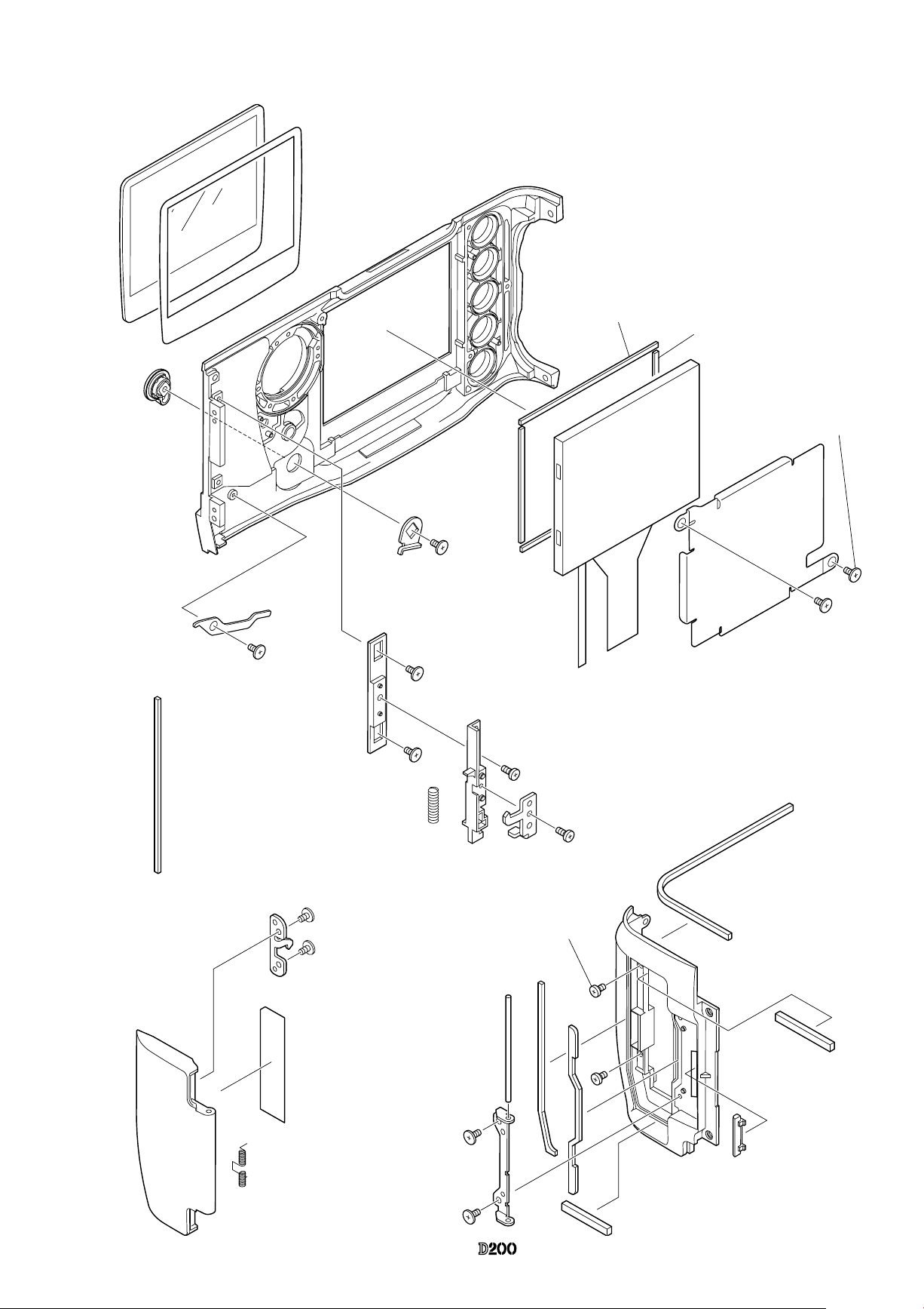
Disassembly
1. Separate Front and Rear bodies
External rubber
WB
Q
U
A
R
I
S
O
#B60
#B447
#B61
#B63
・
Remove the external rubbers
(#B63,#B60,#B61,and #B447).
Bottom cover
・
Remove the battery lid (by tilting and pulling it).
・
Take out two screws (#1556), six screws (#1549) and two screws (#1547).
・
Remove the bottom cover.
#1547
#1549×6
#1556
Bottom cover
#1556
#1547
- D3 ・ -
VBA13001-R.3677.A
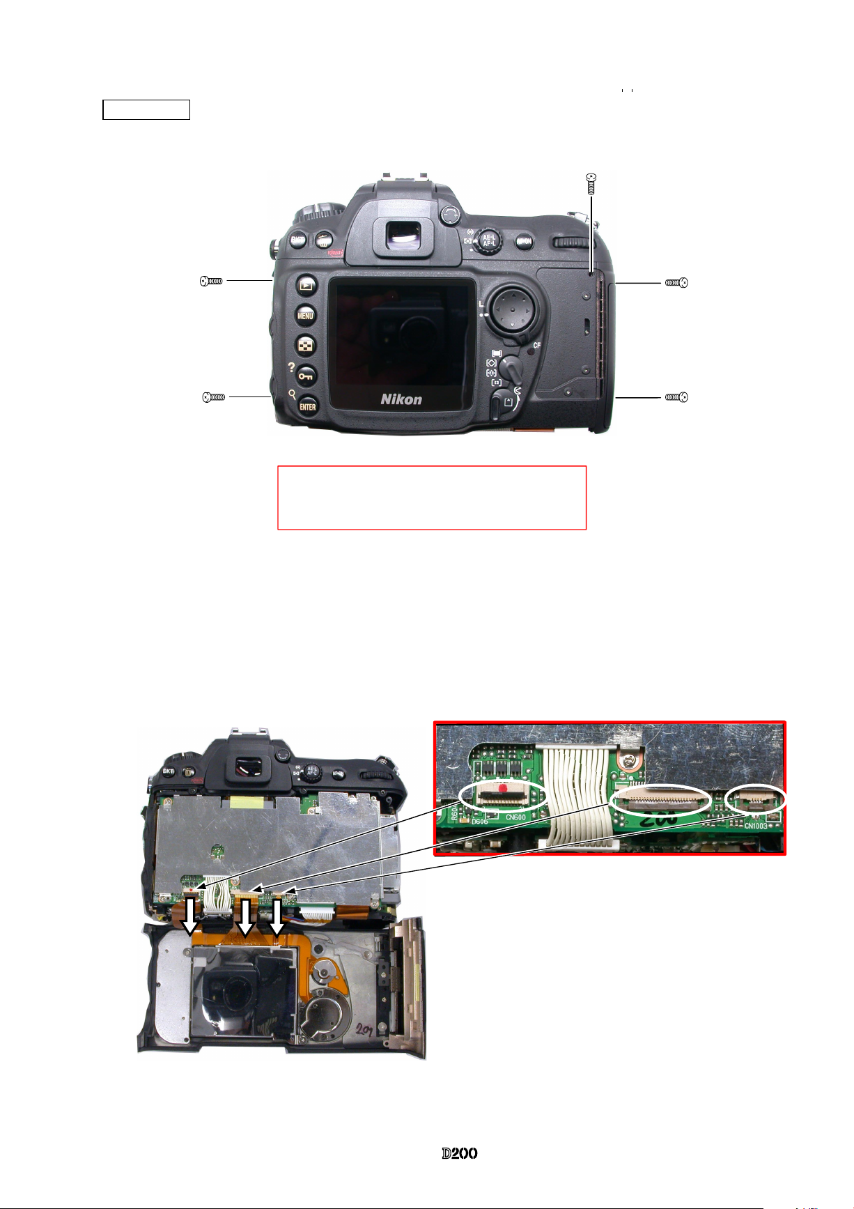
・
Remove the three TFT-PCB connection FPCs from the connector.
Rear cover
・
Take out two screws (#1552), two screws (#1547) and one screw (#1549).
・
Remove the rear cover.
#1552×2
#1547×2
#1549
・
Be careful NOT to cut the TFT-PCB connection
FPC that is at the lower side of the rear cover.
- D4 ・ -
VBA13001-R.3677.A
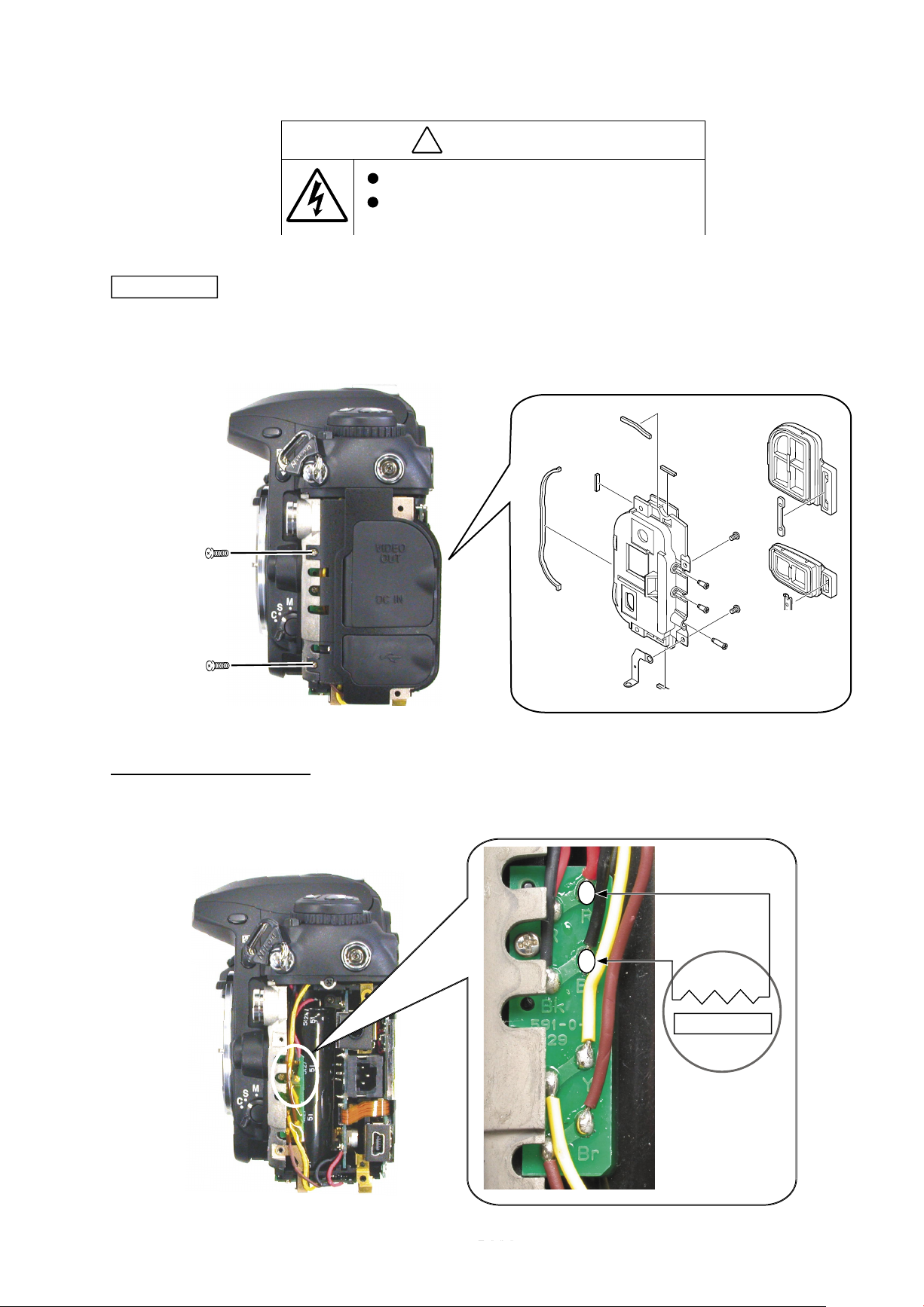
Discharge of Main condenser
・
Discharge the main condenser .
�
内部に高電 圧部 あり 。カ バーを外す時は感電に注意す るこ と。
カバーを外 した 後は 、修 理指針の指示に従ってメイン コン デン
サーの放電 を必 ず行 うこ と。
警告
I/F cover
#1549×2
・
Take out two screws (#1549).
・
Remove the I/F cover unit.
#969
#969
#393
#395
#962×3
#965
#1643
#1642×2
#392
#394
WARNING
Take extra care not to get an electric shock when
detaching covers.
After removing covers, be sure to discharge the main
condenser according to the instructions of repair manuals
.
2KΩ / 5W
- D5 ・ -
VBA13001-R.3677.A
#426
#455
#467
#1538 × 2
#469
#468
#481
#474
#476
#986
#985
#924
#1631
#465
#1511 × 2
#1630
#479
#477
#478
#456
#1511 × 2
#1020
#1512 × 3
#422
#472
#473
#470
#430
#480
#RP00007
Disassemble Rear Cover
- D6 ・ -
VBA13001-R.3677.A
#431
#433
#488
#489
#1629
#434 × 2
#435 × 2
#1057
#1626
#1633
#432
#487
#492
#484
#483 × 2
#485
#1546
#491
#1571
#987
#922
#441
#443
#923
#442
#1628 × 2
#424
#921
#425
#1518 × 2
#486
#440
#1632 × 2
#427
#445
#429
#423
- D7 ・ -
VBA13001-R.3677.A
Soldering bridge
#1515
#1515
#1546×5
・
Take out ve screws
(
#1546) and two screws (#1515).
・
Remove the soldering bridge.
・
Remove the DG shield
plate unit
(#683, #696).
DG shield plate unit
DG-PCB unit
・
Remove the tape (#926).
・
Remove ve FPCs from the connector.
・
Remove the two harnesses from the
connector.
・
Unsolder the four wires.
・
Remove the DG-PCB unit (#B1017).
#B1017 DG-PCB unit
Harness
Harness
DG shield plate
#926
#926

- D8 ・ -
VBA13001-R.3677.A
・
Take out three screws (#1639) and remove the CCD/FPC unit (#B2032).
・
Take out three screws (#1543) and remove the CF card holder (#1018).
CCD/FPC unit
CF card holder
#1639×3
#B2032 CCD/FPC unit
#1543×3
#1018
CF card holder
・
Take out the screw (#1539) and remove the conductive plate (#691).
・
Take out four screws (#1539) and remove the conductive plates (#689, #690,and #688).
・
Remove the main connection FPC (#1035) from the connector of the power drive PCB (#1002).
#1543
Conductive plate
(
#691)
Power drive PCB (#1002)
Conductive plate
(#689)
Conductive plate
(
#690)
#1539
Conductive
plate (
#688)
#1539
#1539
M
サービス
計画課
JUL.7.2006
Change page
△
×1
△
(Addition
)
#1539
△
(Revice
)
#1539

- D9 ・ -
VBA13001-R.3677.A
・
Unsolder six wires.
・
Remove the harness of the back of the power drive PCB.
・
Take out two screws (#1541) and remove the power drive PCB.
Power drive PCB
#1075
Harness: DC/DC PCB
Power drive PCB (#1002)
Yellow: Main-PCB
Brown: Main-PCB
Blue:AF motor
Orange:AF motor
Red: Charge motor
Black: Charge motor
#1541
#1541

- D10 ・ -
VBA13001-R.3677.A
DC/DC PCB unit
・
Unsolder six wires.
・
Take out four screws (#1541) of the DC/DC-PCB (#1047).
・
Remove the harness (#1074) from the DC/DC-PCB (#1047).
・
Remove the harness (#1075) from the DC/DC-PCB (#1047) and from the connector of the power drive PCB
(#1002).
Harness: DG-PCB
#1074
Harness: Power drive PCB
#1075
M
サービス
計画課
JUL.7.2006
Change page
△
×1
Black: Battery contact
Red: Battery contact
Yellow:SBDI-PCB
Brown: SBDI-PCB
Red: IF-PCB
Black: IF-PCB
#1541
#1541
#1541
#1541
△(Addition)
#1047

- D11 ・ -
VBA13001-R.3677.A
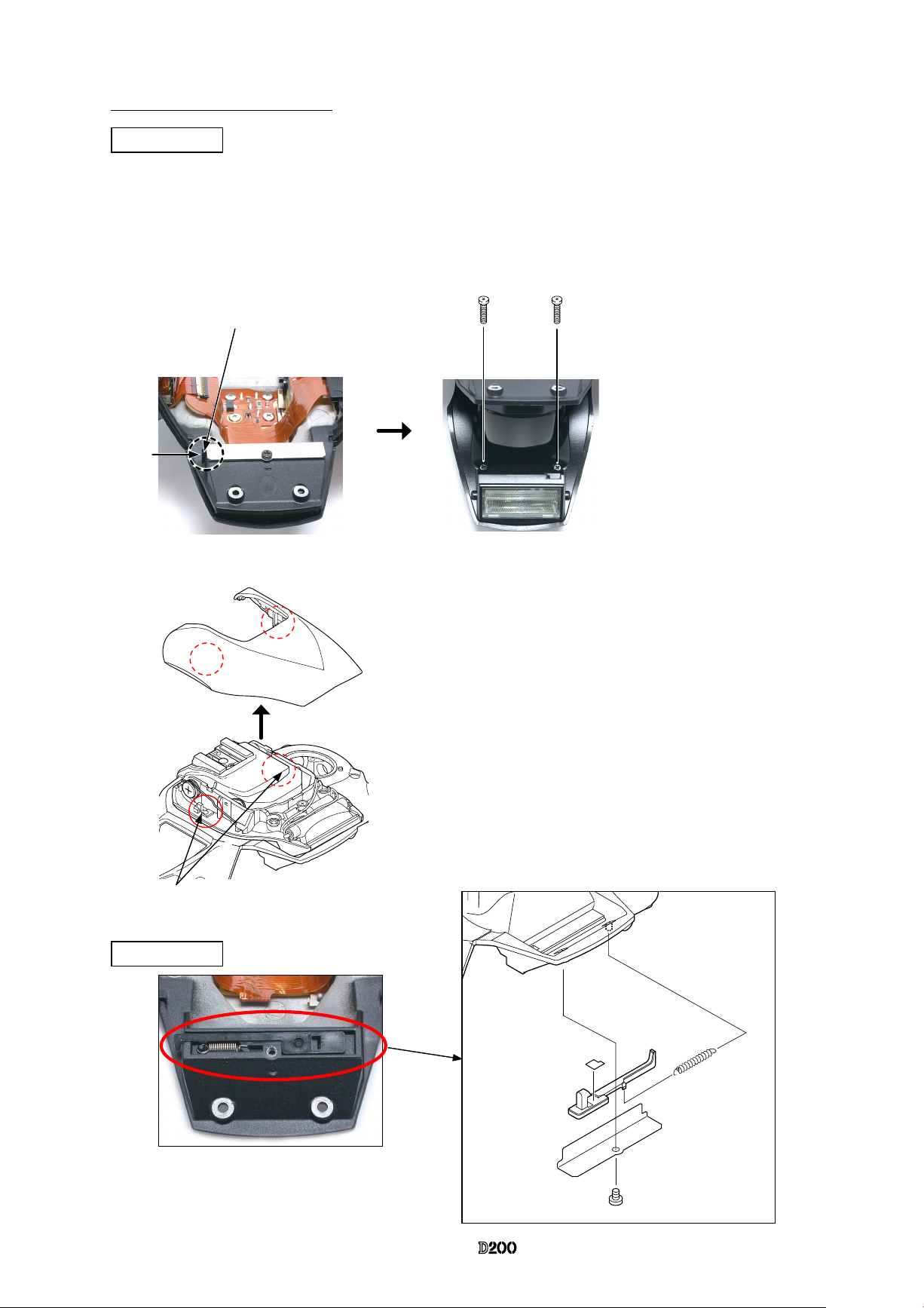
Top cover
・
Remove the tape (#930).
・
Unsolder four wires.
・
Remove the top cover FPC (#1003) from the connector.
#1547
#1547
#1555
#1555
#1511
#1511
・
Remove the cover (#850). Take out the screw (#1622) , and
remove the diopter adjustment knob unit (#852, #857, #851).
・
Pop the SB up, and take out two screws (#1548).
・
Take out two screws (#1511), two screws (#1547) and two
screws (#1555).
・
Lift the top cover unit slowly not to cut the FPC.
#1548×2
Pop this up.
Tape (#930) Red: SB-PCB
Brown: SB-PCB
Yellow: SB-PCB
Black: SB-PCB
#1622
#852
#857
#851
#850
#1555
サービス
計画課
JUL.7.2006
Change page△×1
△
(Addition
)
#1003
- D12 ・ -
VBA13001-R.3677.A
SB upper case
Disassembly of Top cover unit
・
Push the pop-up lever A-part of the top cover unit, and lift the built-in SB.
・
Take out two screws (#1623). (Fig.1)
・
Fold down #301 of the SB lower case on the top cover. Then while holding the hooks of the SB upper case
from both sides by hand, release them from the two holes by sliding/tilting, then remove #301. (Fig.2)
Pop-up lever A-part
Push
#1623×2
Fig.1
SB lower case unit
SB upper case
Fig.2
Holes
Hooks
#301
SB lock cover
#310
#312
#1565
#309
#917C
・
Remove the spring (#310).
・
#309 comes off.
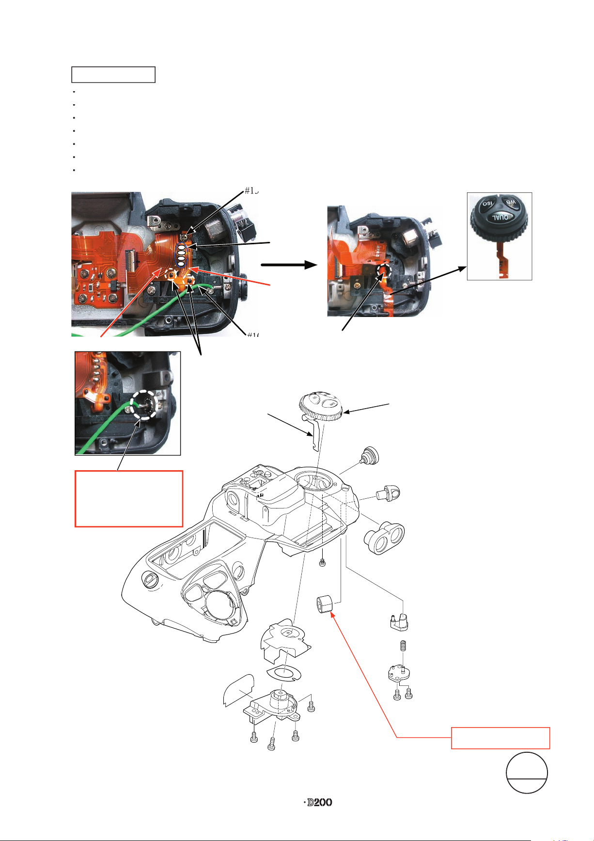
- D13 ・ -
VBA13001-R.3677.A
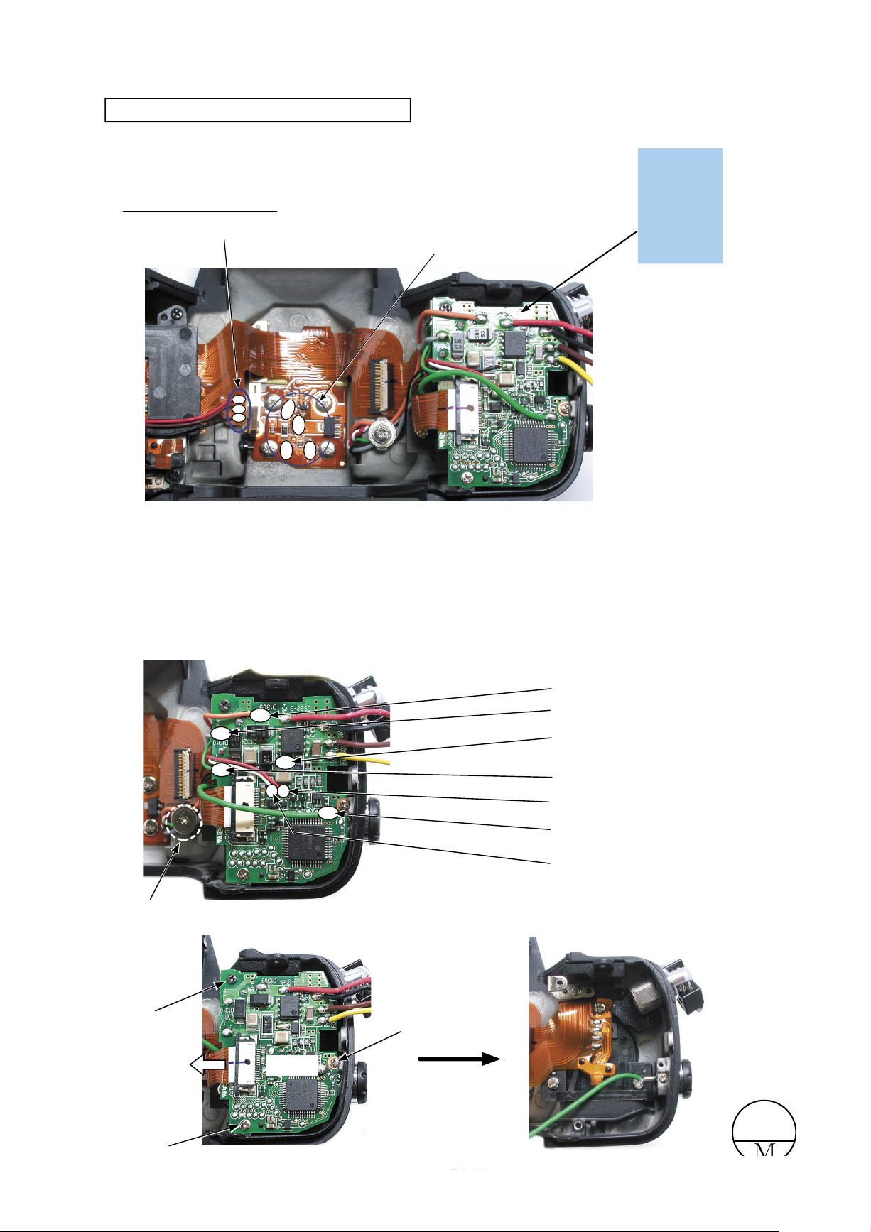
Removal of Top cover FPC / Wires / SB-PCB
・
Unsolder the three metering mode FPC lead wires.
・
Unsolder the accessory shoe contact at four locations.
・
Unsolder the seven lead wires of the SB-PCB.
・
Take out the screw (#1601).
・
Remove the FPC of SB-PCB (#B1013).
・
Take out the screw (#1511).
・
Take out the screw (#1535).
・
Take out the screw (#1541).
Metering mode FPC lead wire
Red×1, Brown×1, Black×1
Red, Brown, Black
△(Revice)
Accessory shoe contact×4
#1541
#1535
#1511
FPC
#B1013
#1601
SB(Black)
SB(Gray)
SB (Green)
SB(Red)
SB(White)
SB(Orange)
Sync terminal(Green)
サービス
計画課
JUL.7.2006
Change page
△× 2
△(Addition)
・It demounts tapes.

- D14 ・ -
VBA13001-R.3677.A
・ Pull each wire from the holes.
・ While releasing the two hooks of the collar (#308), remove #308.
・ Remove the rotation axes (#306 and #307).
・ Remove the SB lower case unit (#B302) from the top cover.
・
Remove the SB-up spring (#305) from the hooking part.
・
Take out the screw (#1601) and remove the SB-up spring (#305).
・
Remove #796, #322, and #325.
SB-up spring
SB lower case unit
#305
Hooking part
#796
#325
#322
#796
#306
#308
#307
#B302
Be careful of the direction of assembling.
Pull six wires out from the holes.
Hooks
#1601
#305
M
サービス
計画課
JUL.7.2006
Change page
△× 1
△(Revise)
#796×2
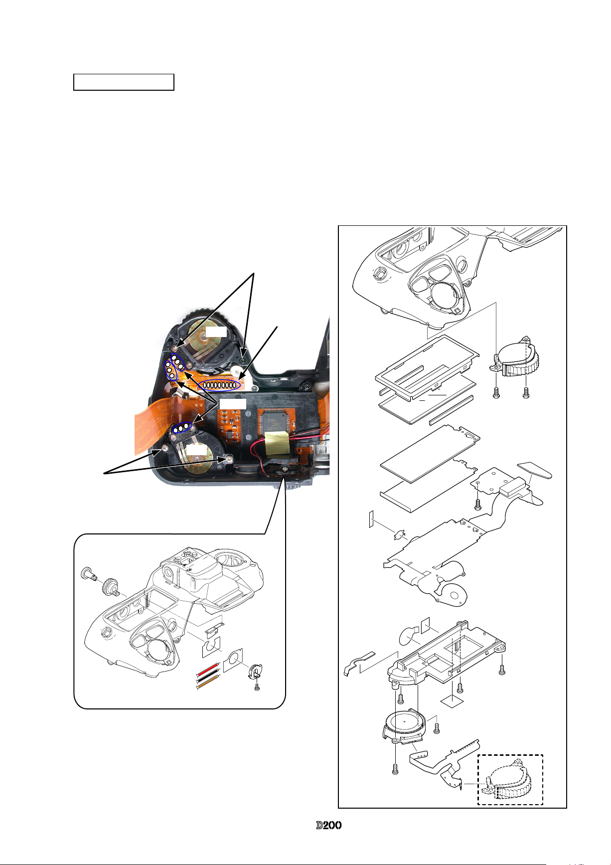
M/DFPC unit
Remove the FPC soldering bridges of #1025 and #1026.
Take out the screw (#1569).
Detach #1025 from the bosses.
Unsolder the lead wire (#1094).
Remove the solder of the lead wire (#1094).
Lift the FPC, and take out the screw (#1572).
Remove B502 and B504 (Trefoil button unit).
Soldering
bridge
#1026
#1569
#1569
Boss
#1025
#1094 Green
Trefoil button unit
Screw (#1572)
Use the Hexagonal wrench
of 5-mm diameter
#B502
#509
#B505
#50
#B43
#1532
#1572
#46
#1569
#513
#508
#510
#1544×2
Q
U
A
R
I
S
O
#1569
#1569
#B504
#514
#515
When removing the solder
on the synchro-terminal
unit, unsolder within 2 sec.
△
(Addition
)
Changed page △×2
△
(Addition
)
M
サービス
計画課
Aug.8.2006
- D16 ・ -
VBA13001-R.3677.A
・
Remove the soldering bridges .
・
Unsolder the SUB dial command unit (B725) .
・
Take out two screws (#1544).
・
Remove the SUB command dial unit (B725).
・
Unsolder the MAIN command dial unit (B726) .
・
Take out two screws (#1571).
・
Remove the MAIN command dial unit (B726).
・
Remove the relies SW unit .
Top cover FPC unit
#39
#965
#B725
#703
#1003
#705
#321×4
#704
#1033
#913
#1053
#912
#974
#706
#973
#1544×2
#1571×2
#B726
#707×2
#1544×3
#929
#1544
×2
#1571
Soldering bridge × 9
Solder
B726
B725
#784
#1535
#1119(Black)
#781
#1028
#780
#1117(Red)
#1118(Brown)
#B782
#914

- D17 ・ -
VBA13001-R.3677.A
Release button / Other small parts
#742
#743
#24
#1608×2
#733
#732
#911
#730
#734
#1604
#1557×2
#1652
#749
#748×2
#701
#787
#B43
#1659
#RP5
#966
- D18 ・ -
VBA13001-R.3677.A
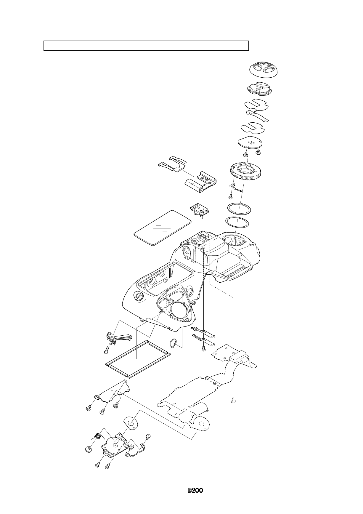
Outer LCD window / Shoe mold unit / Accessory shoe / Other small parts
W
B
Q
U
A
R
I
S
O
#323
#324
#1565
#701
#B317
#316
#318
#746
#1533
#507
#504
#512
#1606
#747
#1547×2
#750
#B735
#327
#511
#1605
#516
#1026
#501
#503
#1560
#731
#753
#1540×2
#502
#765×2
#766×2
#1640×2
#1537×2
- D19 ・ -
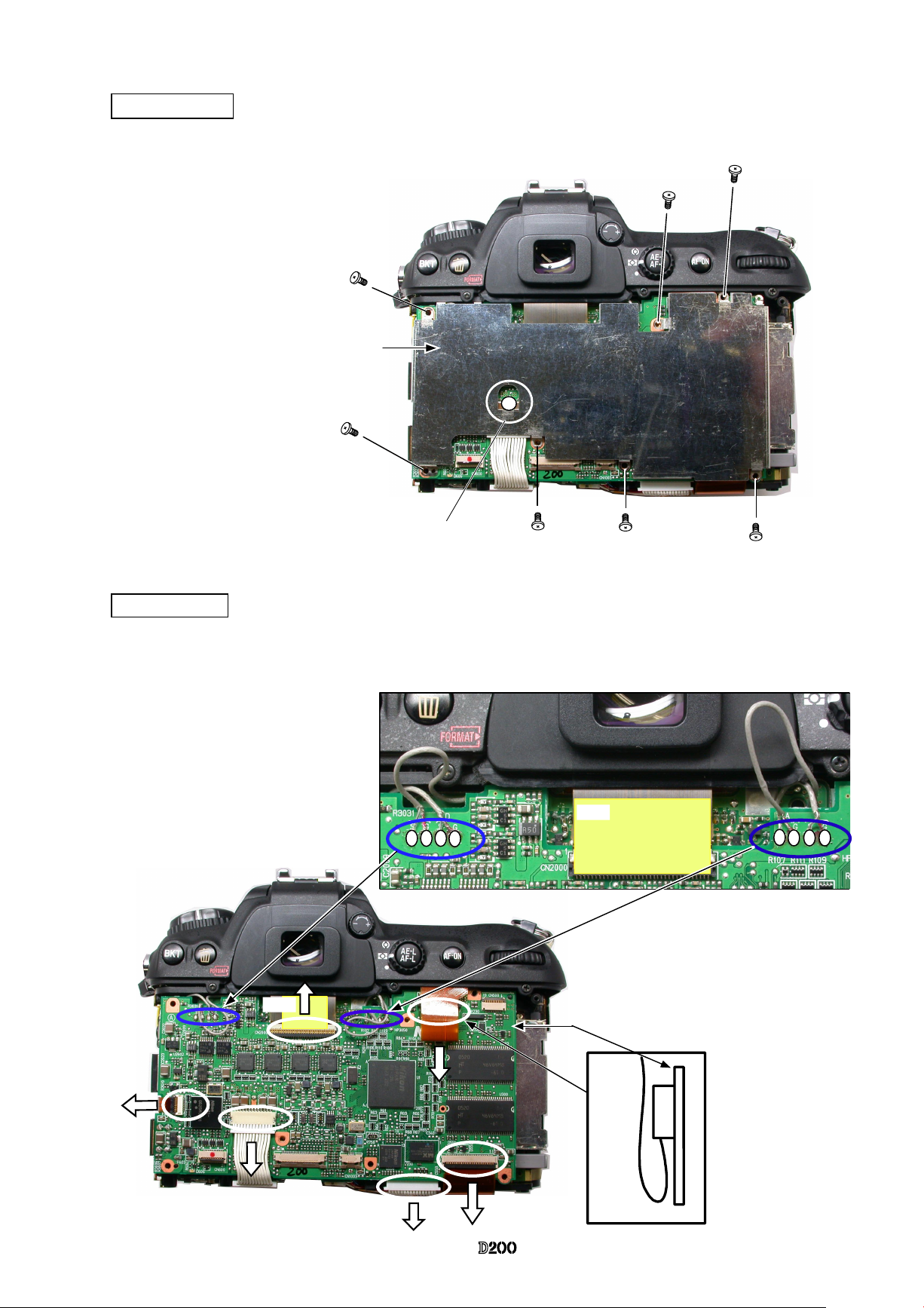
VBA13001-R.3677.A
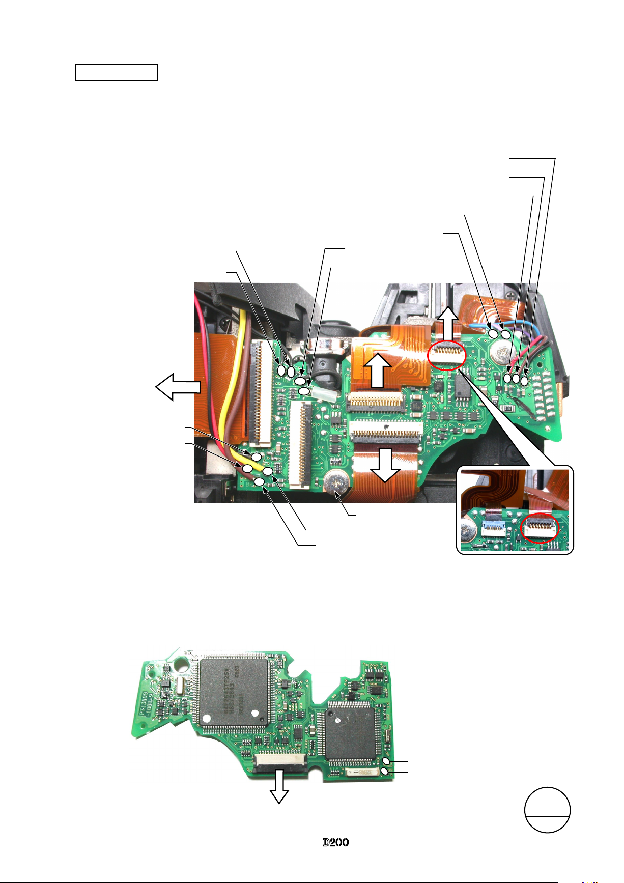
Main PCB unit
・
Unsolder thirteen wires.
・
Remove ve FPCs from the connector.
・
Take out three screws (#1616) and remove the main PCB unit (#B1001).
Brown:
Lens contact FPC
Black:
10-pin
FPC
Red:
10-pin FPC
Yellow: Lens contact
FPC
Black:
Buzzer
Black: Buzzer
Gold
: AF-assist illuminator
Black: AF-assist
illuminator
Blue:FG-ID
Purple: Battery contact
Red: Charge
SW
Brown: Charge
SW
Black: Charge
SW
・
Unsolder the two wires of the back of the main PCB unit (#1001).
・
Remove the main connection FPC (#1035) from the connector of the back of the main PCB unit (#1001).
Back of Main PCB (#1001)
Yellow: Power drive PCB
FPC (#1035)
Brown: Power drive PCB
M
サービス
計画課
JUL.7.2006
Change page
△
×1
△(Addition)
#1616×3
- D20 ・ -
VBA13001-R.3677.A
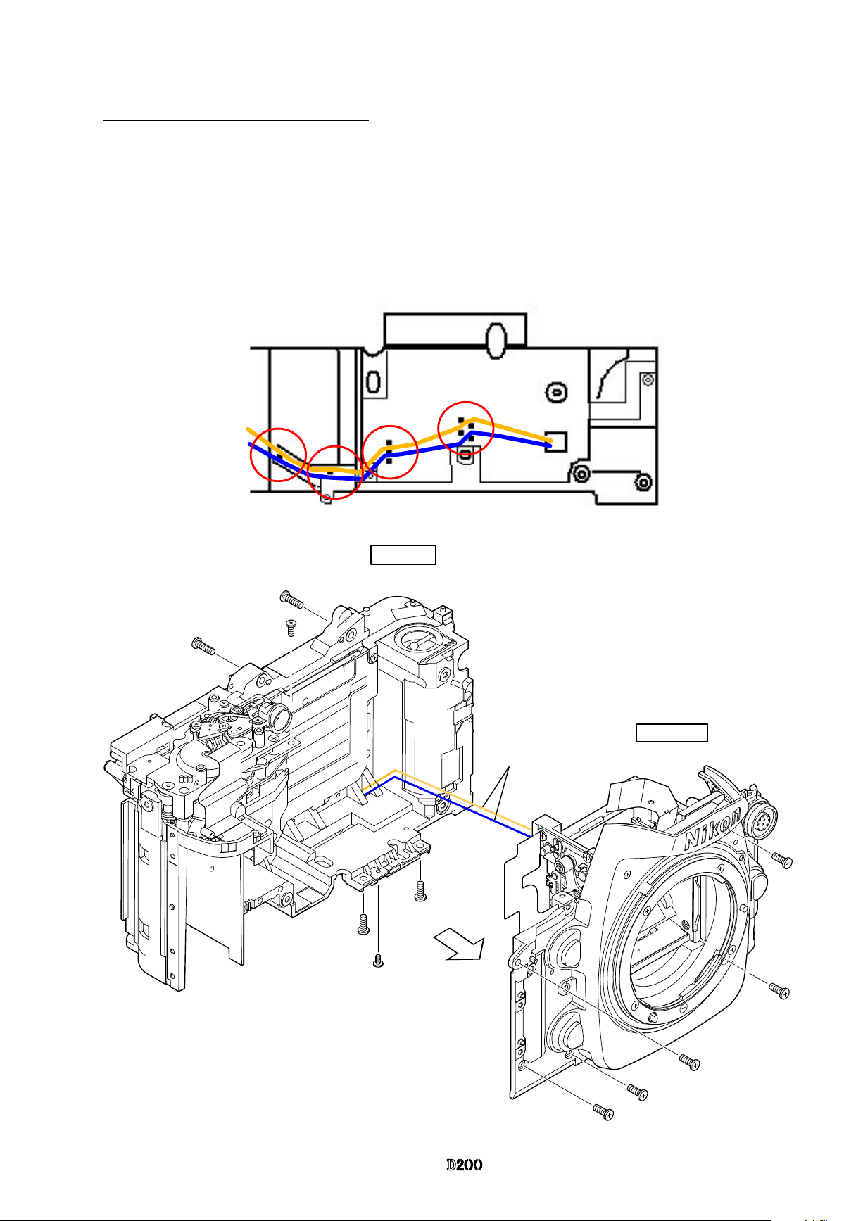
Separation of Front body from Rear body
・
Take out two screws (#1529), one screw (#67), two screws (#1531), one screw (#1525) and ve screws
(#1575).
・
Release the AF motor wires from the bosses, and while pulling them slowly from the holes of the rear
body, remove the front body.
#1575×5
Front body
#1529×2
#67
#1531×2
#1525
Rear body
AF motor wires
AF motor wires
- D21 ・ -
VBA13001-R.3677.A
#439
#1517
#828
#829
#58
#57
#1559
#1515
#952
#1541
#1509
#769
#826
#952
#1509
Grip unit
・
Remove the grip (#57) with the screw (#1515) and two screws (#1509).
- D22 ・ -
VBA13001-R.3677.A
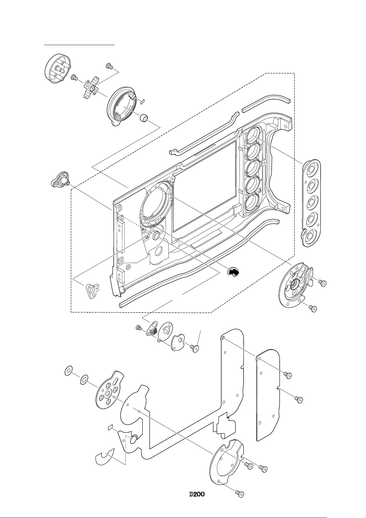
2. Front body
Metering FPC unit
Prism box unit
(with prism and eyepiece)
・
Remove the metering FPC from the connector of the SI-
FPC (#1005).
・
Take out three screws (#883), and remove the metering
FPC unit (#B10006).
・
Three springs (#884) come off.
・
Take out two screws (#1617) and remove the metering
FPC unit pedestal (#B882).
Caution:
The screw (#883) is attached with the
adhesive.
In case the screw (#883) is moved, the
AECCD positioning adjustment (ref.
Assembly) becomes necessary.
#1617×3
#883×3
#B1006
#884×3
#B882
#1005
#1525
#1525
#1528
#1528
・
Remove the lens contact FPC unit (#B1008) from the
connector of the SI-FPC (#1005).
・
Take out two screws
(
#1525) and two screws
(
#1528), and
remove the prism box unit from the front body.
A
A
B
B
- D23 ・ -
VBA13001-R.3677.A
Eyepiece lens-barrel unit
Inner LCD unit
#7
#847
#B846
#844
#849
#841
#845
#5
#842
#858
#854
#853
#848
#856
#1539
#1539
#1619x2
・
Take out two screws (#1619), and remove the eyepiece lens-barrel unit.
・
Remove the nder-display FPC (#1004) from the connector of the SI-FPC.
・
Take out two screws (#1618), and remove the nder-display LCD unit.
#1618×2
#1054
#1004
#1056
#879
#878
#1005
A
A
- D24 ・ -
VBA13001-R.3677.A
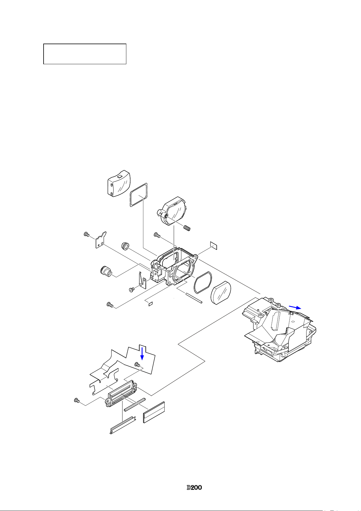
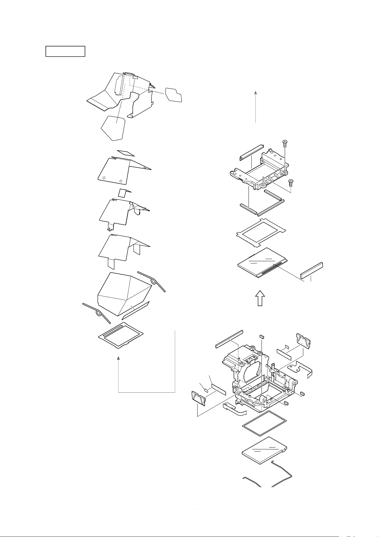
Penta unit
#8
#832
#1619x2
#875x2
#876
#833
#1055
#834
#901
#838x2
#839
#837
#904
#840
#955
#B1005
#954
#953
#835
#873x2
#872x2
#874x2
#902
#3
#877A~B
#836A~C
#877C×2
*
*
- D25 ・ -
VBA13001-R.3677.A
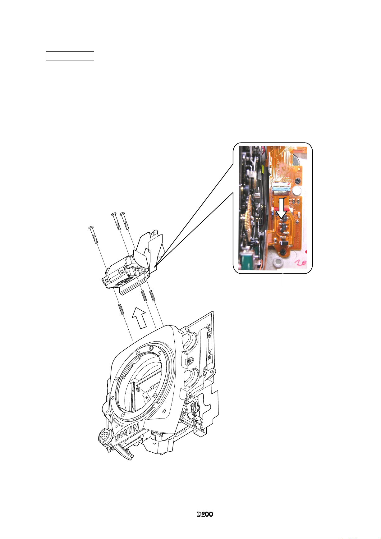
AF-PCB unit
・
Take out the screw (#1507).
・
Remove the AF-PCB FPC from the connector.
・
Take out the three screws (#295) with the Hexagonal wrench, and remove the AF-PCB unit (#B1007).
・
Three springs (#293) come off.
#1507
#295×3
#B1007
#293×3
 Loading...