

Nikon COOLSCAN LS-10E, COOLSCAN LS-10 Instruction Manual

Nikon
35mm Film Scanner
IllCOOLSCRn
III
(LS-IOE
Standard model &
LS-lO
Internal-mount model)
Instruction
manual
Before operating the unit, please read this manual throughly
and retain it for future reference.
Mode
d'emploi
Avant la mise en service de cet appareil, priere
de
lire attentivement
ce
mode d'emploi et de
Ie
conserver pour toute reference future.
Bedienungsanleitung
Lesen
Sie
vor der Inbetriebnahme diese Anleitung sorgfiiltig durch
und bewahren
Sie
sie
zum spiiteren Nachschlagen gut
auf
.
2
Table
of
Content
Chapter 1 Getting Started
1-1 Unpacking .....................................
......
...........
.... ..
. 4
1-2 Checking the Parts
List ........
................................ 4
1-3 Components of Internal -mount Model (LS-
10)
.... 4
1-4 Components of Standard Model (LS-10E)
..
......... 6
1-5 Software Backups ......................................
..
......... 6
1-6
Minimum
System .................................................. 6
1-7 Notes on Use ........................................................ 8
Chapter 2
Setting the Standard Model (LS-10E)
2-1
Setting Up the LS-10E
Scanner
..........................
14
2-2 Setting the SCSI
10
.............................................
16
2-3
Terminating
the SCSI Cha in ..............................
20
2-4 Connecting to the
Computer
SCSi .................
....
22
2-5 Setting Up the SCSI Chain .............. ................... 24
2-6 Setting Up a SCSI Chain with
the
LS-10E .........
26
Chapter 3 Setting
Up
the Internal-mount Model
(LS-10)
3-1 Setting Up the LS-10 Scanner
..
.....................
..... 28
3-2 Installing the LS-
10
Scanner ..............................
30
3-3 Setting the SCSI
10
............................................. 40
3-4
Terminating
the SCSI Cha in ..............................
46
3-5 SCSI Cables Used with Internal Scanners ........ 46
3-6 Connecting to the
Computer
SCSi ..................... 48
3-7
Setting Up a SCSI Chain with the LS-10
50
Chapter 4 Using the Scanner
4-1
Knowledge
of
Films
..........................................
..
52
4-2 Operation to Use a
Slide
Film ...........................
54
4-3 Operation to Use a Strip Film
Holder
................
62
4-4 Focus .......................................... ............ .............
70
4-5
Calibration
........................................................... 74
4-6
LEO
Indicator ......................................................
76
4-7 TERM.
PWR Switch .............................................
76
Specifications ................................................................
78

Sommaire
Chapitre 1
Mise en route
1-1
Oeballage .................
............................................. 5
1-2 Verification du contenu .
..
..................................... 5
1-3 Pieces du
modele
interne (LS-10) .......................
5
1-4 Pieces du modele standard (LS-10E) .................. 7
1-5 Copies
de
sauvegarde
du logiciel ...................... . 7
1-6 Configuration
minimum
........................................ 7
1-7 Notes d'utilisation ................................... ...........
..
. 9
Chapitre 2
Raccordement
du
modele standard
(LS-10E)
2-1
Preparation du
scanner
LS-10E
.........................
2-2
Selection d'iO SCSI
........ .......... ......................
.. ..
2-3
Terminaison de la chaine SCSI
. . . . . . . . . . . . . . . . . . . . . . . . .
2-4 Connexion SCSI a I'unite centrale . . . . . . . . . . . . . . . . . . . . .
2-5 Etablissement de la chaine SCSI
..
...... ...
...........
2-6 Integration du LS-10E a la chaine SCSI ............
Chapitre 3 Montage
du
modele Interne (LS-10)
15
17
21
23
25
27
3-1
Preparation du
scanner
LS-10 ...........................
29
3-2 Installation du scanner LS-
10
............................
31
3-3 Selection d'iO SCSi ............................................
41
3-4 Terminaison de la chaine SCSi ................
...
......
47
3-5 Cables SCSI utilises avec des scanners
internes ...............................................................
47
3-6 Raccordement au port
SCSI
de I'unite
centrale .
..
........................
............
....
....................
49
3-7 Integration du LS-
10
a la chaine SCSi ...........
...
51
Chapitre 4
Utilisation
du
scanner
4-1
Connaissance des films .................................
....
53
4-2 Numerisation de diapositives ....
....
....
.............
...
55
4-3 Numerisation de film en bande .........................
63
4-4
Mise
au point ......
...
........................... ..................
71
4-5
Calibrage
.............................................................
75
4-6 Oiode-temoin ..........................
............................. 77
4-7 Interrupteur TERM.
PWR ..............................
....
.. 77
Caracteristiques ......................
.......
.................... ...........
79
Inhaltsverzeichnis
Kapitel1 Vorbereltungen
1-1
Auspacken ...........................................
...
.............. 5
1-2 Prufen
der
Teileliste ............................................. 5
1-3 Teile des Einbaumodells (LS-10) .........
..
.............. 5
1-4 Teile des Standard-Modells (LS-10E) ................
..
7
1-5 Sicherungskopien
der
Software ........................... 7
1-6 Gerate-Mindestanforderungen .....
.....
................... 7
1-7
Allgemeine Hinweise ........................................... 9
Kapitel2
AnschluB des Standard-Modells (LS-10E)
2-1
Aufstellen des externen Scanners LS-10E
...
.....
15
2-2
Einstellen
der
SCSI-Adresse ............................
..
17
2-3 AbschluB
der
SCSI-Kette ...................
...
........
...
...
21
2-4 AnschluB an die SCSI-Schnittstelle
des Computers .......... ........ ...........
......... ............
..
23
2-5 Aufbau
der
SCSI-Kette ...................... .................
25
2-6 Aufbau
einer
SCSI-Kette
mit
dem LS-10E ....
.....
27
Kapitel3
AnschluB des Einbaumodells (LS-10)
3-1
3-2
3-3
3-4
3-5
3-6
3-7
Montage des Scanners LS-10 ....................
...
...
..
29
Einbau des Scanners LS-10 ........
.......................
31
Einstellen
der
SCSI-Adresse ............................
..
41
AbschlieBen
der
SCSI-Ketle .
....
..........................
47
SCSI-Kabel des Einbau-Scanners .....................
47
AnschluB an die SCSI-Schnittstelle des
Computers .
.................................................
......... 49
Aufbau
einer
SCSI-Kette
mit
dem LS-10
51
Kapitel4
Bedienung des Scanners
4-1 Grundsatzliches zum Film ..........................
....
....
53
4-2 Verwendung von Umkehrfilm ... ..........................
55
4-3 Verwendung des Filmstreifenhalters .................
63
4-4 Scharfeinstellung ................................................
71
4-5 Kalibrierung ..............................................
...
....
...
75
4-6
LEO-Anzeige .....................................
....
.............. 77
4-7 AbschluBstromschalter (TERM.
PWR)
...............
77
Technische Daten .........................................
....
.............
79
3
4
~
lhliID[lil
U
®1f
11
I
Getting Started
1-1
Unpacking
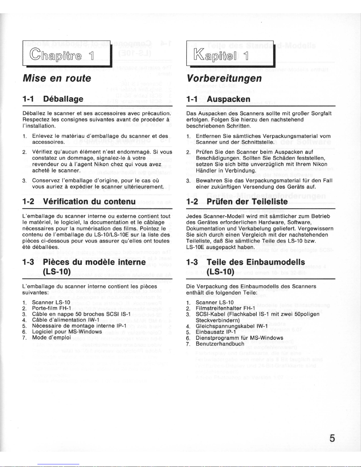
Care should be exercised when unpacking the
scanner
.
Follow the
instructions
below
before
beginning
the
installation
procedure
.
1.
Remove all packaging
materials
from
the
scanner
and the interface kit.
2. Check
for
damage
while
unpacking the
scanner
. If
you notice any
damage
, notify the
dealer
or
the
Nikon
sales
office
where
you purchased the
scanner
.
3.
Save all
shipping
and packaging
materials
in case
you
want
to
ship
the
scanner
in the future .
1-2 Checking the Parts List
Each
scanner
package,
whether
internal
or
external ,
includes
all
of
the
necessary
hardware, software
,
documentation and
cabling
to get you to started
scanning
film
. Check the
components
in the LS-101
LS-10E packaging
against
the
following
parts
list
to
insure
that you have unpacked
all
contents.
1-3 Components of Internal-mount
Model (LS-10)
The internal
scanner
package contains the
following
items:
1.
Scanner LS-10
2. Strip
film
holder
FH-1
3.
SCSI 50-pin
flat
cable
IS-1
4.
DC
power
cable
IW-1
5.
Internal
mounting
kit IP-1
6. Utility
software
for
MS-Windows
7.
User's
manual
Mise
en
route
1-1
Oeballage
Deballez Ie
scanner
et ses accessoires avec precaution.
Respectez les consignes suivantes avant de proceder
a
I'installation .
1. Enlevez Ie materiau d'
emballage
du
scanner
et
des
accessoires.
2. Verifiez qu'aucun
element
n'est
endommage. Si vous
constatez un dommage,
signalez
-Ie a votre
revendeur
ou a I'agent Nikon chez qui vous avez
achete Ie
scanner
.
3. Conservez I'emballage d'
origine, pour
Ie cas
OU
vous
auriez a expedier
Ie
scanner
ulterieurement.
1-2 Verification
du
contenu
L'emballage
du scanner interne ou externe contient tout
Ie materiel , Ie logiciel , la documentation et Ie cablage
necessaires
pour
la
numerisat
ion des
films
. Pointez
Ie
contenu de
I'emballage
du LS-10/LS-
10E
sur
la liste des
pieces ci-dessous
pour
vous
assurer
qu 'elles ont to utes
ete deballees .
1-3 Pieces
du
modele interne
(LS-10)
L'
emballage
du
scanner
interne contient les pieces
suivantes:
1. Scanner LS-
10
2.
Porte-film
FH-1
3. Cable en nappe
50
broches SCSI
IS-1
4. Cable d'alimentation IW-1
5. Necessaire
de
montage interne
IP-1
6. Logiciel
pour
MS-Windows
7. Mode d'emploi
Vorbereitungen
1-1
Auspacken
Das Auspacken des Scanners sollte mit groBer Sorgfalt
erfolgen. Foigen Sie hierzu den nachstehend
beschriebenen Schritten.
1. Entfernen Sie samtliches Verpackungsmaterial yom
Scanner und
der
Schnittstelle.
2. Priifen Sie den Scanner beim Auspacken auf
Beschadigungen. Sollten Sie Schaden feststellen,
setzen Sie sich bitte unverziiglich mit Ihrem Nikon
Handler in Verbindung.
3.
Bewahren Sie das Verpackungsmaterial fUr den Fall
einer
zukiinftigen Versendung des Gerats auf.
1-2
PrOfen
der Teileliste
Jedes Scanner-Modell wird
mit
samtiicher
zum Betrieb
des Gerates erforderlichen Hardware, Software,
Dokumentation und Verkabelung
geliefert
. Vergewissern
Sie sich durch einen Vergleich
mit
der
nachstehenden
Teileliste,
daB
Sie samtliche Teile des LS-10 bzw.
LS-10E
ausgepackt haben.
1-3 Teile des Einbaumodells
(LS-10)
Die Verpackung des Einbaumodells des Scanners
enthiilt
die
folgenden Teile :
1. Scanner LS-10
2. Filmstreifenhalter
FH-1
3. SCSI-Kabel (Flachkabel
IS-1
mit zwei 50poligen
Steckverbindern)
4. Gleichspannungskabel
IW-1
5. Einbausatz IP-1
6. Dienstprogramm
fiir
MS-Windows
7. Benutzerhandbuch
5
6
1-4 Components
of
Standard Model
(LS-10E)
The external
scanner
package contains the
following
items:
1. Scanner LS-10E
2. Strip
film
holder
FH-1
3.
SCSI
cable
SS-lO
4. SCSI
terminator
ST-1
5.
AC
power
cable
PW-2
6. Plug-in
software
for
Photoshop
7. Utility
software
for
MS-Windows
8.
User's
manual
1-5 Software Backups
As with any software, it is
wise
to make a
complete
backup
of
the
software
disk
and store the
master
disk
in
a safe place.
Always
work
with
the backup copies when
installing
the Nikon
software
.
1-6 Minimum System
As an absolute
minimum
, an IBM PC-type
computer
system must have the
following
components
:
1. 386
or
486 Processor
2. 1 Megabyte of
memory
3.
Super
VGA
graphic
card
4.
Windows 3.0
or
later
installed
5. SCSI Bus
or
card
slot
for
the SCSI card included
The
recommended
computer
system
should
have at
least
4 to 8 megabytes of
memory
with a 16- to 32-bit
color
graphic
adapter
.
As an absolute
minimum,
the Macintosh-type
computer
system must have the
following
components :
1.
Most
of Macintosh models
(More
than 640 x 480 dots
of
monitor
resolution
is
required
.), such as
Powerbook,
II
, Centris and
Quadra
series
.
2. Apple Macintosh system 6.07
or
later
3. 32-bit Quick
Draw
4. 4 MB RAM
(8
MB
is recommended)
5. Hard
disk
(300
MB
is recommended)
6.
Color
display & video
card
capable
of
more
than
8-bit
color
reproduction (Full
color
display
& 24-bit
video
card
are
recommended)
7. Adobe Photoshop
version 1.07
or
later
1-4 Pieces
du
modele standard
(LS-10E)
L'emballage
du
scanner
standard contient
les
pieces
suivantes
:
1.
Scanner LS-10E
2.
Porte-film
FH-1
3.
Cable SCSI
SS-lO
4. Bouchon
de
terminaison
SCSI
ST-1
5.
Cable
secteur
PW-2
6.
Logiciel
additionel
pour
Photoshop
7.
Logiciel
pour
MS-Windows
8.
Mode d'emploi
1-5 Copies de sauvegarde
du
logiciel
Comme
pour
tout
logiciel
, il est avise de faire une
copie
de
sauvegarde
complete
de la disquette du
logiciel
et
de
ranger
la
disquette d'origine
dans
un
endroit
sOr.
Travaillez
toujours
avec
les
copies
lorsque
vous
installez
Ie
logiciel
Nikon.
1-6 Configuration minimum
Pour les
ordinateurs
de
type IBM
PC,
la configuration
minimum
est la suivante :
1.
Processeur
386 ou 486
2. 1
Mo
de
memoire
vive
3. Carte
graphique
super
VGA
4.
Windows 3.0 ou
ulterieur
installe
5. Bus SCSI ou fente
pour
la carte SCSI installee
II
est
recommande d'utiliser
en
pratique
une
configuration
disposant
de
4 a 8 Mo de
memoire
vive,
dotee
d'une
carte
graphique
couleur
de 16 a
32
bits .
Pour les
ordinateurs
Macintosh, la
configuration
minimum
est
la suivante :
1. La
plupart
des
modeles
Macintosh (une
resolution
superieure
a 640 x 480 points
est
requise
pour
Ie
moniteur)
tels
que
les
series
Powerbook, II, Centris
et
Quadra
2.
Ordinateur
Apple
Macintosh au 6.
07
ou
ulterieur
3. Quick Draw
32
bits
4. 4
Mo
de
memoire
vive
(8
Mo
recommandes)
5.
Disque
dur
(300 Mo recommandes)
6. Affichage
couleur
et
carte
video capables
d'une
reproduction
couleur
de plus de 8 bits (un affichage
"full
color
" et une carte
video
de 24 bits
sont
recommandes)
7. Adobe Photoshop
version 1.07
ou
ulterieure
1-4 Teile des Standard-Modells
(LS-10E)
Die Verpackung
des
externen Scanner-Modells enthi:ilt
die
folgenden Teile :
1. Scanner LS-10E
2.
Filmstreifenhalter
FH-1
3. SCSI-Kabel
SS-lO
4. SCSI-AbschluBwiderstand
ST-1
5.
Netzkabel PW-2
6. Plug-in-Software
fur
Photoshop
7.
Dienstprogramm
fur MS-Windows
8. Benutzerhandbuch
1-5 Sicherungskopien der Software
Wie bei
jeder
Software
empfiehlt
es sich auch hier,
einen kompletten Satz Sicherungskopien herzustellen
und
die
Originale
an einem sicheren
Ort
aufzubewahren.
Benutzen Sie
zur
Installation
der
Nikon Software
ausschlieBlich
die
Sicherungskopien.
1-6 Gerate-Mindestanforderungen
Der
IBM-kompatible
PC
muB folgende
Mindestanforderungen
erfUllen :
1.
Prozessor 386
oder
486
2. 1 Megabyte
Speicher
3. Super-VGA-Grafikkarte
4.
Windows 3.0
oder
spi:iter
installiert
5. SCSI-Bus
oder
Kartenschlitz fUr
die
beigefUgte SCSI-
Karte .
Das empfohlene Computersystem sollte mindestens 4
bis 8
MByte
Speicher
und einen 16- bis 32-Bit-
Colorgrafik-Adapter
haben.
Der
Macintosh-Computer muB folgende
Mindestanforderungen
erfullen:
1. Die meisten
Macintosh-Modelle
(eine Bildaufl6sung
des
Monitors
von
mehr
als 640 x 480 Punkten ist
erforderlich),
wie
z.B.
die
Modelle
der
Serien
Powerbook,
II
, Centris und Quadra
2. Apple Macintosh-System ab Version 6.
07
3.
32-Bit Quick
Draw
4. 4 MB
RAM
(8
MB
ist
empfehlenswert)
5.
Festplatte (300 MB
ist
empfehlenswert)
6.
Farbdisplay und Grafikkarte,
die
fUr
eine
Farbwiedergabe
von
mehr
als 8
Bit
tauglich sind
(Vollfarben-Display und 24-Bit-Grafikkarte sind
empfehlenswert)
7.
Adobe Photoshop ab Version 1.
07
7
8
1-7 Notes
on
Use
Power source
1.
Always
use the
power
source
of
100
- 240 V,
50-60
Hz.
Use the
power
cord
subject
to the voltage of
power
source, and if you use
over
AC125 V:
• the plug must be rated
for
AC250 V
15
A
(NEMA6P-15) .
• the insulation of the cord must be
more
than SVT
type, and be a
suitable
cord
of
at
least
AWG18 and
approved
under
safety
regulations
of the nations in
which it is used.
2. Once the
power
source
is turned off, do not turn it
on until at
least 5 minutes
have passed.
3. Don
't
unplug the unit
while
the
power
is on.
4.
Don't hold the cord
itself
when
unplugging
the unit.
5. The
power
source
must be
grounded
. A jOint
ground
with
other
instruments
is
indispensable, or
else
a
ground
loop, which can cause
electrical
shocks and
electrical
noise,
may
result.
6. Don
't
unplug the
peripherals
while
the
power
is on.
7. Don't
carry
the main unit
while
the
power
is on.
• Be
sure
to use the
unit
in a
horizontal
orientation
only
;
a
perpendicular
orientation
will
cause
misoperation
.
• Don't use a
slide
mount
more
than 3
mm
thick. If
the
slide
mount is not flat on its surface, you
may
feel
some
roughness when
mounting
or
unmounting
the
slide
.
• Don't force the
slide-mount
or
strip
film
holder
into
or
out of the
scanner
if
it
does not move
smoothly
.
• When
moving
the scanning stage, don't touch
or
unmount
the
strip
film
holder
.
• Don't
disassemble
the main unit. It is
dangerous
to
touch the internal components because
of
high-voltage .
• Don
't
put the
things
inside
the unit.
Flammable
materials
, metals,
water
etc
.,
will
cause
fire, electrical
shock,
damage
and
misoperation
.
In
emergency
If you find
something
unusual, such as
abnormal
noise,
smells
or
smoke,
turn
off the
power
switch
, and take the
unit
to the
dealer
from whom you purchased it.
1-7 Notes d'utilisation
Alimentation
1. Utilisez
toujours
un secteur
compris
entre
100
et
240
volts, 50 a 60 Hz.
Utilisez un cordon
secteur
approprie
a la tension
d'
alimentation, et
si cette tension est
superieure
a
125 V:
• la
prise
doit
etre
aux
normes
250 V 15 A
(NEMA6P-15).
• I'isolation du cordon
doit
etre
superieure
au type
SVT, et la section des conducteurs
superieure
ou
egale
a AWG18, et Ie
cordon
d'un type
agree
dans Ie
pays d'utilisation.
Si vous
utilisez
une tension
egale
ou
inferieure
a
125 V:
• la
prise
do it etre aux
normes
AC125 V
10
A.
2. Si vous coupez I'
alimentation
du
scanner
, ne la
retablissez
pas avant cinq
minutes
.
3. Ne
debranchez
pas Ie cordon d'
alimentation
lorsque
Ie
scanner
est sous tension.
4.
Ne pas
brancher
et
debrancher
la
prise
en la
tenant
par
Ie cordon.
5.
II
est
necessaire
de
relier
Ie
scanner
a la
terre
. La
connexion
de
terre
concentree
par
tous les
appareils
relies
entre
eux est
indispensable
pour
un bon
fonctionnement
; sinon, cela peut
former
une boucle
d'induction
generatrice
de
parasites
.
6. Ne
jamais
debrancher
un
peripherique
sous tension.
7.
Ne pas
deplacer
I'unite
centrale
lorsqu '
elle
est sous
tension
.
• Le
scanner
doit
reposer
sur
une surface horizontale.
Si on Ie place
verticalement
, ceci se
traduira
par
des
anomalies
.
• Ne pas
utiliser
de
montures
de
diapositives
d'
epaisseur
superieure
a 3 mm. Si la monture de la
diapositive
ne repose pas a plat, I'on
ressentira
parfois
une resistance
lors
de
I'introduction
ou du
retrait
de
la
diapositive
.
• Si I'on ressent une
telle
resistance, ne pas
forcer
pour
i
ntroduire
ou
retirer
la
diapositive
ou Ie porte-film.
• Ne pas
toucher
Ie porte-film pendant la
numer
isation.
• Ne pas
demonter
I'unite
centrale
. La haute tension
presente
un
danger
mortel.
• Ne pas i
ntroduire
de
corps
etrangers
a I'
interieur
de
I'
unite
centrale
. Des objets inflammables, metaux, eau,
etc
.,
peuvent
provoquer
un
incendie
, une electrocution ,
des
dommages
et des
anomalies
.
En
cas d'urgence
Si
vous
trouvez
quelque
chose
d'anormal, bruit, odeur
,
fumee, coupez
I'alimentation
et faites
parvenir
Ie
scanner a votre
revendeur.
1-7 Allgemeine Hinweise
Spannungsquelle
1.
Das von Nikon
mitgelieferte
Netzkabel entspricht den
einschliigigen
Bestimmungen
iiber
die
elektrische
Sicherheit. Wenn Sie ein
anderes
Netzkabel
verwenden , achten Sie auf das Vorhandensein des
VDE- bzw. TOV-Priifzeichens. Die
Priifwerte
250
V
und
15 A diirfen
nicht unterschritten werden!
2.
Nach dem Ausschalten des Geriites miissen
mindestens
fiinf
Minuten verstreichen ,
bevor
das
Geriit
erneut
eingeschaltet
wird
.
3. Der Netzstecker
darf
nur bei ausgeschaltetem
Geriit
gezogen werden.
4. Fassen Sie das Netzkabel zum Trennen
der
Verbindung
grundsiitzlich
nur
am Stecker,
niemals
direkt
am Kabel!
5. Der NetzanschluB muB unbedingt
geerdet
sein
. Die
Erdung
ist
beim Betrieb
mit
anderen Geraten
unerliiBlich , da sonst eine Erdschleife entsteht,
die
zu
elektrischen Schliigen und Rauschen fiihren kann.
6. Die Verbindung zu Peripheriegeraten
darf
nur
bei
ausgeschaltetem
Gerat
unterbrochen werden.
7. Das
Geriit
darf
nur
in ausgeschaltetem Zustand
transportiert
werden .
• Das
Geriit
darf
nur
in
horizontaler
Stellung betrieben
werden . Bei
vertikaler
Aufstellung ist ein
fehlerfreier
Betriebsablauf
nicht
gewiihrleistet.
• Die
maximal
zuliissige
Dicke von Diariihmchen betragt
3 mm. Falls
die
Oberfliiche
des
Diariihmchens
nicht
flach
ist
, kann
das
Einsch ieben
oder
Auswerfen des
Dias manchmal nicht ganz reibungslos ablaufen.
• Bei Einlegen
oder
Entnehmen des Dias
oder
Filmstreifenhalters
ist
jede
Gewaltanwendung zu
vermeiden
.
• Wah rend des Scannens
darf
der
Filmstreifenhalter
weder
beriihrt
noch entnommen werden.
•
Jeder
Eingr
iff in das
Geriit
ist
zu unterlassen. Durch
Hochspannung
droht
Lebensgefahr!
• Das
Geriiteinnere
darf
nicht
mit
Fremdkorpern in
Beriihrung
kommen . Metall, Wasser und
brennbare
Materialien
konnen Feuer, elektrische
Schliige
,
Geriiteschiiden
oder
Betriebsstorungen verursachen.
In
einem Notfall
Schalten Sie das
Geriit
im Faile
ungewohnlicher
Geriiusch-
, Geruchs-
oder
Rauchentwicklung
unverziiglich
ab und
verstiindigen
Sie den Nikon
Kundendienst.
9

10
Safety regulation
Hinweis:
Dieses Gerat entspricht
der
europaischen
Sicherheitsnorm EN60950, hat
die
GS-Marke erhalten
und
erflillt
die
Norm-Vfg 243/1991 Klasse B fUr unnotige
Sekundarstrahlung. Dieses Gerat sollte
nur
in
Ausrlistung eingebaut werden,
die
denselben Normen
(TOV,
f-Marke usw.) entspricht.
For regular use
Avoid using and storing the scanner in locations
that
are
:
* extremely hot
or
cold . (from +10 to +35 *
C)
*
near
heat sources
or
in
direct
sunlight.
* exposed to moisture
or
dust.
* exposed to hard vibration.
Avoid hard physical shocks to the main unit.
Note
on
transportation
When transporting the main unit, always use
the
packaging materials in which the main
unit
was
packed
when you purchased it. The focus dial must be turned
downward to the end before packing. If you have lost the
packaging materials , use materials designed to protect
precision instruments from vibration and physical
shocks . Be especially careful when using
air
or
courier
service.
Taking this product out
of
country
The use of this product may violate local
laws
and
restrictions in some countries. If this is the case, we can
not
bear
any responsibility for any
violations
resulting
from the use of this product. Note that, in
some
countries, this product can be made to conform with
regulations through an internal adjustment. Therefore ,
before taking this product out of the country,
consult
with
your
service representative .

Reglementations de securite
Hinweis
:
Dieses Gerat entspricht
der
europaischen
Sicherheitsnorm EN60950, hat die GS-Marke erhalten
und erfUlit die Norm-Vfg 243/1991 Klasse B fUr unnotige
Sekundarstrahlung. Dieses
Gerat
sollte
nur
in
Ausrustung eingebaut werden,
die
denselben Normen
(TOV,
f-Marke usw .) entspricht.
Conditions d'utilisation normales
Evitez d'
utiliser
et de stocker Ie scanner dans les
conditions ci-dessous :
• froid ou
chaleur
extremes (temperature recommandee
de
+10 a +35' ).
• pres d'une source de chaleur, ou sous la
lumiere
solaire
directe.
• dans des endroits excessivement poussiereux ou
humides
• dans des conditions
de
fortes vibrations .
Manipulez
Ie
scanner avec precautions, et evitez les
chocs.
Remarques sur Ie transport
Si
vous devez
expedier
Ie
scanner
, utilisez les
materiaux d'
emballage
et
Ie conditionnement avec
lesquels Ie
scanner
vous a ete livre. La molette de mise
au
point
doit
etre positionnee a fond vers Ie bas avant
I'emballage
. Si vous ne disposez plus des materiaux
d'emballage
d'origine,
procurez vous des materiaux
identiques, qui
amortissent
les chocs
et
absorbent les
vibrations. Soignez
particulierement I'emballage
pour
les expeditions par
Air
ou Poste.
Utilisation de ce produit
it
I'etranger
L'utilisation
de
ce produit peut
contrevenir
a la
reglementation et aux restrictions locales
de
certains
pays. Dans
un
tel cas, notre responsabilite ne
saurait
etre engagee pour toute infraction resultant
de
I'utilisation de ce produit. Notez, toutefois , que, dans
certains pays, il est possible de rendre ce produit
conforme
a la reglementation par un reglage interne.
Avant d'utiliser
ce produit a
I'etranger
, adressez-vous
donc
a votre agent de service apres-vente.
Sicherheitsbestimmung
Hinweis:
Dieses Gerat entspricht
der
europaischen
Sicherheitsnorm EN60950, hat die GS-Marke erhalten
und erfUlit
die
Norm-Vfg 243/1991 Klasse B fUr unnotige
Sekundarstrahlung. Dieses Gerat sollte
nur
in
Ausrustung eingebaut werden, die denselben Normen
(TOV
, f-Marke usw.) entspricht.
1m
Normalbetrieb
Vermeiden Sie die Benutzung bzw. Aufbewahrung des
Scanners unter den nachfolgend aufgefUhrten
Bedingungen.
•
An
sehr
heiBen
oder
kalten Orten (auBerhalb von +10
bis +35·
C).
•
In
der
Nahe von Hitzequellen
oder
im direkten
Sonnenlicht.
• Bei
sehr
hoher Feuchtigkeit oder starkem Staub.
• Bei starken Schwingungen.
Schutzen Sie das Gerat vor Schlagen.
Transporthinweise
Versenden
Sie das Gerat ausschlieBlich in
seiner
Originalverpackung. Die Feinfokussierung
muB
vor dem
Einpacken ganz nach unten gedreht werden . Sollte
die
Originalverpackung nicht
mehr
zur Verfugung stehen, ist
auf besonders widerstandsfahige Verpackung zu achten,
wie
sie fUr Prazisionsgerate geeignet ist. Dies
gilt
besonders
fUr
den Versand auf dem Luftwege oder per
Spediteur.
Benutzung dieses Produktes
im
Ausland
Der Betrieb dieses Produktes kann in einigen Landern
gegen die ortlichen Gesetze und Bestimmungen
verstoBen. So lite dies
der
Fall sein, so ubernehmen
wir
keinerlei Haftung fur etwaige VerstoBe, die auf den
Betrieb dieses Produktes zuruckzufuhren sind . Wir
weisen darauf hin,
daB
fur
einige Lander eine interne
Einstellung an diesem Produkt notwendig sein kann, urn
es den geltenden Bestimmungen anzupassen. Wenden
Sie sich
daher
an
Ihre Kundendienststelle, bevor Sie
dieses Produkt ins Ausland mitnehmen.
11
12
Note on installation
1. Turn off the
power
switches
for
the equipment. (The
LS-10
is not provided with a
power
switch . Always
turn off the switch on the computer .)
2. Turn off the
power
switches
for
all the devices
(printer
, display) connected to the computer.
3. Move the key to the unlock position if the computer
has a key-lock mechanism.
4. Unplug all the cables, including the
power
cords .
5.
Remove the cover of computer as described in the
manual.
6. Remove the
cover
of the bay as described in the
manual.
Warnlngl
Electro.taUc discharge
will damage the scanner If
you touch the scanner'. connector pin
•.
Do not
touch the pin
•.

Remarques sur I'installation
1. Mettez
I'interrupteur
des
peripheriques
sur
Arret.
(Le LS-10 ne dispose pas d'un
interrupteur
: coupez
toujours I'alimentation de I'unite centrale.)
2. Mettez tous les
interrupteurs
de tous les
peripMriques
(imprimante
, ecran) relies a I'unite
centrale
sur
Arret.
3. Mettez Ie cas
ecMant
la cle de securite de I'unite
centrale
sur
deverrouillage.
4.
Deconnectez to us les cables
relies
a I'unite centrale ,
y
compris
Ie cable secteur.
5. Deposez Ie capot de I'unite centrale selon les
instructions de son mode
d'emploi.
6. Deposez Ie capot du
logement
selon les instructions
du mode d'emploi.
Attentlonl
Une decharge d'61ectrlclt6 statlque peut gravement
endommager les circuits du scanner. Ne touchez
Jamals les broches
du
connecteur du scanner.
Installationshinweise
1. Schalten Sie die Hauptschalter
der
Gerate aus.
(Der LS-10 besitzt keinen eigenen Hauptschalter.
Schalten Sie das Gerat stets
mit
dem Hauptschalter
des Computers aus.)
2. Schalten Sie auch samtliche an den Computer
angeschlossenen Peripheriegerate aus (Drucker,
Monitor
usw.).
3. Sofern
der
Computer
mit
Schlussel
verr
iegelt
werden kann,
muB
er
geoffnet werden .
4. Trennen Sie den Computer von
der
Netzspannung
und entfernen Sie
aile
von auBen eingesteckten
Kabel.
5.
Entfernen Sie das Computergehause
wie
im
Computer-Handbuch beschrieben.
6.
Entfernen Sie die Abdeckung des Laufwerkschachts
wie
im Computer-Handbuch beschrieben .
Achtungl
Vermelden Sle
Jede
Beriihrung
der
Steckerkontaktel
Elne elektrostatlsche Entladung kann das
Gerlt
beschldlgenl
13
[8]
Fig.
2.1
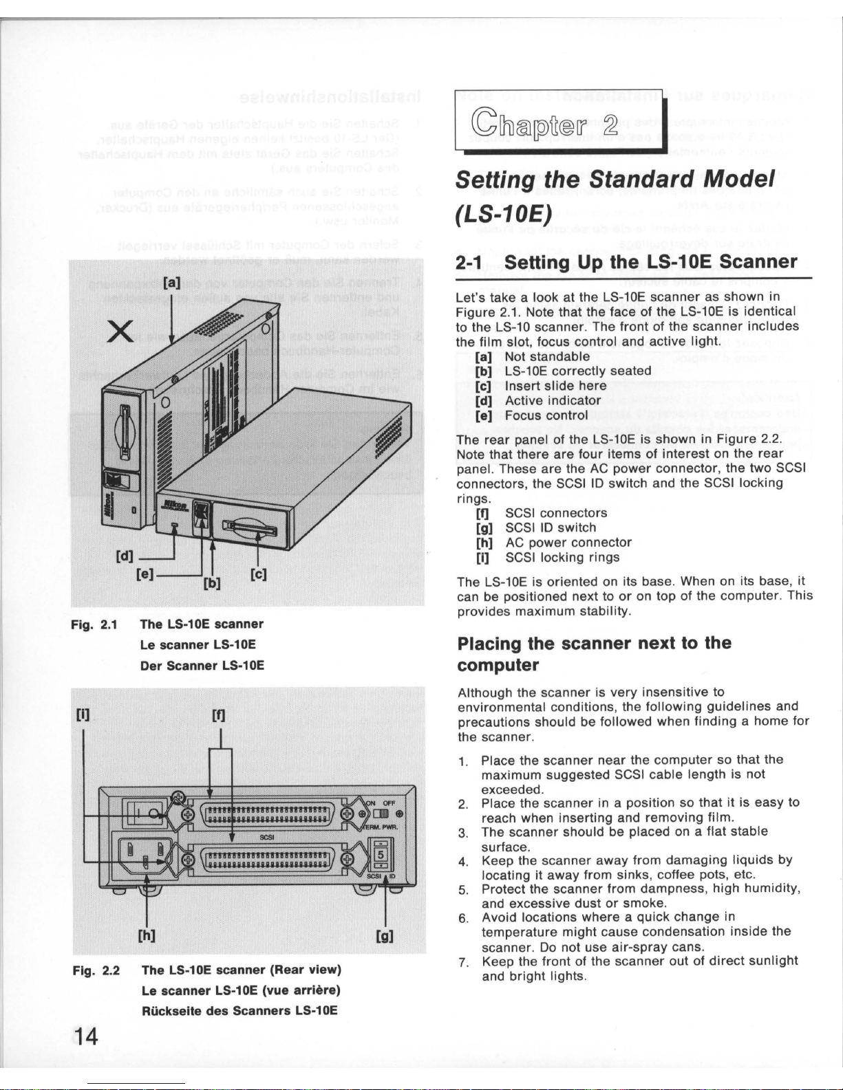
The LS·10E scanner
Le scanner LS·10E
Der Scanner LS·10E
[I]
[f]
[h)
Fig. 2.2 The LS·10E scanner (Rear view)
Le scanner LS·10E (vue arriere)
Riickselte des Scanners LS·10E
14
[g)
~1li®[pJfi®1l'
~
I
Setting the Standard
Model
(LS-10E)
2-1
Setting Up the LS-10E Scanner
Let's take a look
at
the LS-10E scanner as shown in
Figure
2.1
. Note that the face of the LS-10E is identical
to the LS-10 scanner . The front of the
scanner
includes
the film
slot
, focus control and active light.
[a] Not stand able
[b]
LS-10E
correctly seated
[c] Insert
slide
here
[d] Active indicator
[e] Focus control
The rear panel of the LS-10E is shown in Figure 2.2.
Note that there
are
four items of
interest
on the
rear
panel. These are the
AC
power
connector, the
two
SCSI
connectors, the SCSI
10
switch and the SCSI locking
rings.
[f]
[g]
[h]
[I]
SCSI connectors
SCSI
10
switch
AC
power
connector
SCSI
locking rings
The LS-10E is oriented on its base. When on its base,
it
can be positioned next to
or
on top of the
computer
. This
provides maximum stability .
Placing the scanner next
to
the
computer
Although the scanner is very insensitive to
environmental conditions, the
following
guidelines
and
precautions should be followed when finding a home
for
the scanner.
1. Place the scanner
near
the
computer
so that the
maximum suggested SCSI cable length is not
exceeded .
2. Place the
scanner
in a position so that it is easy to
reach when inserting and removing
film
.
3. The scanner should be placed on a flat stable
surface .
4. Keep the scanner
away
from
damaging
liquids
by
locating it away from sinks , coffee pots, etc.
5. Protect the
scanner
from dampness ,
high
humidity,
and excessive dust
or
smoke.
6. Avoid locations
where
a quick change in
temperature might cause condensation inside the
scanner.
Do
not use
air-spray
cans.
7. Keep the
front
of the scanner out of
direct
sunlight
and
bright
lights.
Raccordement
du
modele
standard (LS-10E)
2-1
Preparation
du
scanner LS-10E
La version du
scanner
LS-10E est representee figure
2.1. Notez que la face avant des versions LS-10E
et
LS-10 est
str
ictement identique . La face avant du
scanner
regroupe Ie
logement
du
film
, Ie voyant
d'activite , et la molette de mise au point.
[a] Ne pas
utiliser
en position verticale
[b] LS-10E
correctement
en
place
[c] Inserez
la
diapositive
ici
[d] Voyant d'activite
[e] Molette
de
mise au
point
La figure
2.2
montre
la face
arriere
du LS-10E: s'y
trouvent la
prise
de
raccordement au secteur , les deux
connecteurs SCSI, Ie selecteur d'
IO
SCSI et les clips de
verrouillage
.
[f] Connecteurs SCSI
[g] Selecteur d'
IO
SCSI
[h] Prise
de
raccordement au secteur
[I] Clips de verrou illage
Le
scanner
LS-10E
doit
etre utilise a I'horizontale .
II
peut alors etre place a
proximite
de ou
sur
I'ordinateur.
Ceci procure une
stabilite
maximale
.
Emplacement du scanner pres de
I'unite centrale
Bien que Ie
scanner
so it
tres
bien protege, iI est
fortement recommande de respecter autant que possible
les indications suivantes lorsqu 'il a ete decide de son
emplacement.
1. Placez Ie scanne r pres de I'unite centrale , sans
depasser la
longueur
de
cable SCSI recommandee.
2. Placez
Ie
scanner a un
endroit
tel que I'insertion
et
Ie retrait des diapositives et du porte-film soient
facile.
3. Le scanner
doit
reposer
sur
une surface plane et
reguliere
.
4. Veillez
a ce que
Ie
scanner ne
soit
pas expose a des
projections de liquide. Eloignez-Ie des
eviers
,
cafetieres, etc.
5. Evitez I'humidite, I'eau, la poussiere excessive
et
la
fumee.
6. Evitez les endroits presentant un risque
de
condensation. N'utilisez
jama
is d'
air
com
prime
,
notamment en bombes ,
pour
Ie depouss ierer.
7.
Evitez que les rayons
solaires
, ou un
eclairage
violent
, ne tombent
directement
sur
la face avant.
I
AnschluB des StandardModells (LS-10E)
2-1
Aufstellen des externen
Scanners LS-10E
Schauen
wir
uns zunachst den in Abb. 2.1 dargestellten
externen Scanner LS-10E an. Die Vorderseite dieses
Gerats ist mit
jener
des Einbaumodells LS-10 identisch.
An
der
Vorderseite befinden sich
der
Filmschlitz,
die
Feinfokussierung und
die
Kontrollampe.
[a] Nicht hochkant stellen
[b] LS-10E in korrekter Lage
[c] Schlitz zum Einlegen des Oias
[d] Kontrollampe
[e] Feinfokussierung
Die ROckseite des LS-10E ist in 2.2 abgebildet. Sie
enthalt vi
er
Elemente: den AnschluB
fOr
den Netzstecker,
die beiden SCSI-Steckverbinder, den SCSIAdressenschalter und
die
SCSI-Klemmen.
[f] SCSI-Steckverbinder
[g] SCSI-Adressenschalter
[h] NetzanschluB
[I] SCSI-Klemmen
Oer externe Scanner (LS-10E) muB horizontal aufgestellt
werden . Somit kann
er
neben oder auf dem Computer
stehen , so daB maximale Stabilitat gewahrleistet ist.
Aufstellung des Scanners neben dem
Computer
Wenngleich
der
Scanner recht unempfindlich gegenOber
den Umgebungsverhaltnissen ist, sollten bei
der
Wahl
des Aufstellungsorts folgende Kriterien in Betracht
gezogen werden.
1. Stellen Sie den Scanner so nah am Computer auf ,
daB
die
vorgeschriebene
Maximallange
des SCSI-
Kabels nicht Oberschritten wird.
2. Stellen Sie den Scanner so auf,
daB
er
zum Einlegen
und Entnehmen des Films leicht zu erreichen ist.
3. Stellen Sie den Scanner auf
einer
ebenen , stabilen
Flache auf .
4. Stellen Sie den Scanner auBer Reichweite von
schiidlichen FIOssigkeiten auf , d.h. keinesfalls in
der
Nahe von AusgOssen, Kaffeemaschinen usw.
5. SchOtzen Sie den Scanner vor Nasse, Feuchtigkeit,
Staub und Rauch.
6. Vermeiden Sie Aufstellungsorte,
an
denen plotzliche
Temperaturschwankungen
zur
Kondenswasserbildung innerhalb des Scanners
fUhren k6nnten. Verwenden Sie keine SprOhdosen.
7. SchOtzen Sie die Vorderseite des Scanners
vor
direktem Sonnenlicht und starken Kunstlichtquellen.
15
16
Connecting
AC
power
to
the scanner
The
scanner
power
cord
is a standard
three-wire
grounding
plug. This plug
will
fit
only a grounded
AC
outlet. Intended to be a safety feature, the
grounding
connector should not be removed . Use of a
transient
protected
power
source
is
highly
recommended
. The
scanner
would
ideally
be turned on and off with the
computer
.
Always
remove
the
power
cord from the AC
source
when
anyone
of
the
following
occurs
:
1. The
power
cord
or
plug becomes
damaged
.
2.
Any
liquids
are
spilled
into the
scanner
.
3. The
scanner
is exposed to
excessive
moisture
.
4. The case of the
scanner
has
become
damaged
.
5. The case is opened.
6.
You think the
scanner
is not functioning
properly
and
requires
repair
.
2-2 Setting the SCSI
10
Up to
eight
devices can
share
a SCSI
device
. These
are
each identified by SCSI
10
numbers
. Thus , a SCSI
10
can
have a value between 0 and 7.
There
are
no
implicit
regulations
regarding
the use
of
these numbers.
Typically, the
computer
controller
would be SCSI
10
number
0,
while
the SCSI
peripherals
would be 1
through 7.
A
minimum
of
two
devices
must
sit
on any SCSI bus . In
this case, one is designated as the
initiator
while
the
other
is the target. It is
possible
to have
many
configurations of
initiators
and
targets
on a bus.
More
than one
initiator
can be
present
on a SCSI bus. The
typical configuration is one
initiator
and one
or
more
targets. The LS-10/LS-10E
scanner
is
always
a target. In
the case we show
below
there
is
only
one
initiator
of
the
computer.
The SCSI
10
is
typically
set
by a switch on the
rear
of
the SCSI peripherals. The
default
SCSI
10
number
set
at
the factory is
10
#5.
Raccordement
au
secteur
Le cordon d'alimentation
trifilaire
du scanner est un
cordon type
pour
raccordement aux
prises
de terre.
II
doit
etre utilise
sur
des prises raccordees a la
terre
. Par
mesure de securite , la connexion
de
mise a la
terre
ne
doit
jamais
etre
interrompue
ou
supprimee
. L'utilisation
d'un
filtre
secteur
supprimant
les
transitoires
est
recommandee. Idealement, Ie
scanner
devrait
etre mis
so us tension
et
hors tension avec
I'ordinateur
.
Toujours commencer
par
deconnecter Ie cordon
d'alimentation
du secteur dans les cas suivants:
1.
Le cordon est
abime
ou la
prise
est endommagee .
2. Le scanner a
rec;:u
du liquide accidentellement.
3. Le scanner presente des traces d'
humidite
.
4. Le boWer du
scanner
est
endommage.
5. Le boWer du
scanner
est
ouvert
.
6. Le
scanner
ne
semble
pas fonctionner correctement
et
necessite une reparation.
2-2 Selection
d'ID
SCSI
Huit dispositifs SCSI peuvent etre relies simultanement
a un SCSI.
lis
sont identifies
par
un numero , I'ID SCSI,
qui peut
prendre
les valeurs de 0 a
7.
II
n'y a pas de
regie absolue dans I'affectation des ID SCSI. On attribue
generalement
1'10
SCSI 0 au contr61eur de I'unite
centrale, les
ID
1 a 7 etant destinees aux peripheriques
SCSI.
Un
minimum
de deux dispositifs SCSI
doivent
etre
raccordes
a
un
bus SCSI. Dans ce cas, un des
dispositifs est qualifie de
maitre
, et I'
autre
d'esclave.
II
est possible de raccorder a un bus SCSI
plusieurs
dispositifs maltres en
meme
temps que
plusieurs
dispositifs esclaves. La configuration la plus frequente
est
toutefois un
dispositif
maitre
raccorde a plusieurs
dispositifs esclaves . Le scanner LS-10/LS-10E est
toujours
un
esclave . Dans Ie cas indique ci-dessous,
iI
y
a
seulement
un maitre
de
I'unite centrale.
L'ID SCSI se choisit
generalement
a I'aide d'un
commutateur
situe a
I'arriere
des
peripMriques
SCSI.
L'
ID
SCSI par defaut est
ID
5.
NetzanschluB des Scanners
Das Netzkabel des Scanners ist
mit
einem dreipoligen
Erdungsstecker versehen,
der
nur
in geerdete
Steckdosen paBt.
Da
es sich bei
der
Erdung urn eine
SicherheitsmaBnahme han de It, sollte diese keinesfalls
umgangen werden. Die Verwendung
einer
gegen
SpannungsstoBe abgesicherten Spannungsquelle
wird
dringend
empfohlen.
1m
Idealfall sollte
der
Scanner
zusammen mit dem Computer ein- und ausgeschaltet
werden .
Ziehen Sie den Netzstecker des Scanners in den
folgenden Fallen:
1.
Wenn das Netzkabel oder
der
Netzstecker schad haft
ist.
2. Wenn
der
Scanner
mit
einer
Flussigkeit in
Beruhrung gekommen ist.
3.
Wenn
der
Scanner ubermaBiger Feuchtigkeit
ausgesetzt ist.
4. Wenn das Gehause des Scanners schad haft
geworden ist.
5. Wenn das Gehause geoffnet werden soil.
6. Wenn
der
Scanner nicht einwandfrei zu funktionieren
scheint und instandgesetzt werden muB.
2-2 Einstellen
der
SCSI-Adresse
Bis
zu
acht Gerate konnen sich eine SCSI-Schnittstelle
teilen . Jedes Gerat
erhalt
dabei eine SCSI-Adresse, die
zwischen 0 und 7 liegen kann. Fur
die
Verwendung
dieser
Zahlen gibt es keine festen Vorschriften.
Normalerwe
ise ist die
Nummer
0 fUr den SCSI-Controller
im Computer reserviert, wah rend die SCSIPeripheriegerate die Nummern 1 bis 7 erhalten.
Mindestens zwei Gerate mussen sich auf jedem SCSIBus befinden. Dann
gilt
eines als Haupt-, das andere als
Nebengerat. Viele verschiedene Konfigurationen von
Haupt- und Nebengeraten sind auf einem Bus moglich.
Auch
mehr
als ein Hauptgerat kann sich auf einem
SCSI-Bus befinden. Bei
der
typischen Konfiguration
handelt es sich urn ein Hauptgerat und ein oder
mehrere
Nebengerate. Der LS-10/LS-10E ist
immer
ein
Nebengerat.
In
unserem gezeigten Fall gibt es
nur
ein
Hauptgerat.
Die SCSI-Adresse wird im allgemeinen
mit
einem
Schalter an
der
Ruckseite
der
SCSI-Peripheriegerate
eingestellt.
1m
Werk wird
die
Nummer 5 als SCSI-
Adresse eingestellt.
17
[b)
J
I~_::-"W-
.+--
[a]
[C]-~HI
5
r
••
1+-
.+--
[d)
SCSI
10
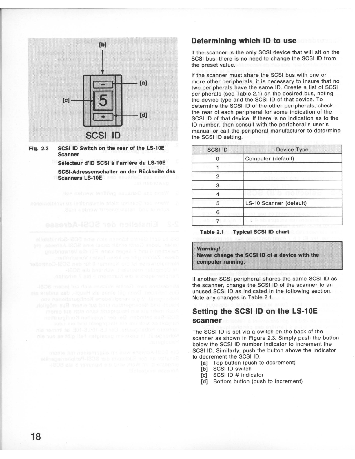
Fig.
2.3
SCSI ID Switch on the
rear
of the LS-10E
Scanner
18
Selecteur d'iO SCSI
Ii
I'arriere
du LS-10E
SCSI-Adressenschalter an
der
Riickseite des
Scanners
LS-1
DE
Determining
which
10
to
use
If
the scanner is the
only
SCSI device
that
will
sit
on the
SCSI bus , there is no need to change the SCSI
10 from
the preset value .
If the scanner must share the SCSI bus with one
or
more
other
peripherals
, it is necessary to insure that no
two
peripherals
have the same 10. Create a
list
of SCSI
peripherals
(see Table 2.
1)
on the desired bus, noting
the device type and the SCSI
10
of
that
device. To
determine
the SCSI 10 of the
other
peripherals
, check
the
rear
of each peripheral for some indication of the
SCSI
10 of that device. If there is no indication as to the
10
number
, then consult with the
peripheral's
user
's
manual
or
call the peripheral manufacturer to
determine
the SCSI 10 setting.
SCSI
10 Device Type
o
Computer (default)
2
3
4
5 LS-10 Scanner (default)
6
7
Table
2.1
Typical SCSI
10
chart
Warnlngl
Never
change the SCSI 10
of a device
with
the
computer
running.
If another SCSI peripheral shares the
same
SCSI 10 as
the scanner, change the SCSI
10 of the
scanner
to an
unused SCSI
10 as indicated in the
following
section.
Note any changes in Table 2.1.
Setting the SCSI 10 on
the
LS-10E
scanner
The SCSI 10 is set via a switch on the back of the
scanner as shown in Fi
gure
2.3. Simply push the button
below the SCSI
10
number
indicator to increment the
SCSI
10
.
Similarly
, push the button above the
indicator
to decrement the SCSI 10.
[a]
Top button (push to decrement)
[b]
SCSI 10 switch
[c]
SCSI 10 # indicator
[d]
Bottom button (push to increment)
Determination de
1'10
Si Ie scanner est
Ie
seul
peripherique
connecte au bus
SCSI, il est inutile de
modifier
cette
10
prereglee
.
Si Ie scanner
doit
cohabiter
sur
Ie bus SCSI avec
d'autres
peripMriques
, il est necessaire de
verifier
que
deux
peripMriques
ne reC(oivent pas la
meme
10
SCSI.
Etablissez une liste de vos peripheriques sous la forme
du
tableau 2.1.
L'
IO
SCSI peut etre relevee
sur
la face
arriere
de
la
plupart
des peripheriques. Si vous ne trouvez pas
d'indication de numero d'IO , consultez
leurs
notices
respectives ou contactez Ie fabricant ou distributeur.
ID SCSI Equipement
0 Unite centrale (par defaut)
1
2
3
4
5 Scanner LS-10 (par defaut)
6
7
Tableau
2.1
Tableau
10
SCSI
AUentlonl
Ne Jamals modUler
1'10
SCSI d'un perlph'rlque
pendant Ie foncllonnement de
I'unlt.
centrale.
Si
un autre
peripMrique
SCSI a la meme
10
SCSI que
Ie
scanner
, modifiez 1'
10
SCSI du
scanner
pour
lui
attribuer
une
10
SCSI
libre
comme
indique dans les sections
suivantes. Notez ces modifications dans
Ie
tableau 2.1.
Selection d'ID SCSI sur Ie Scanner
LS-10E
L'
IO
SCSI est
determinee
par
un commutateur situe
sur
la face
arriere
du scanner,
comme
indique
figure
2.3.
Appuyer
sur
Ie bouton situe au dessous
de
I'indicateur
de
numero d'iO
SCSI
pour
incrementer
et
sur
celui du
dessus
pour
decrementer
.
[a] Bouton
superieur
(appuyer
pour
decrementer)
[b) Commutateur d'
iO
SCSI
[c) Indicateur de
numero
d'iO SCSI
[d) Bouton
inferieur
(appuyer
pour
incrementer)
Ermittlung der einzustellenden Adresse
Wenn
der
Scanner das einzige SCSI-Geriit auf dem
SCSI-Bus ist, besteht keine Veranlassung, die
eingestellte SCSI-Adresse zu iindern.
MuB sich
der
Scanner
mit
einem
oder
mehreren
Peripheriegeriiten den SCSI-Bus teilen,
muB
sichergestellt werden, daB
die
Adressennummern nicht
doppelt vergeben sind. Machen Sie deshalb eine
Aufstellung
der
SCSI-Pheripheriegeriite (siehe Tabelle
2.1) auf dem betreffenden Bus,
der
die entsprechenden
Geriitetypen und SCSI-Adressen zu entnehmen sind.
Urn
die
SCSI-Adresse
anderer
Peripheriegeriite
festzustellen , uberprufen Sie die Ruckseite jedes
Peripheriegeriites auf das Vorhandensein
einer
SCSI-
Adressenanzeige.
1st
eine Adresse nicht bekannt,
schlagen Sie bitte im Handbuch des betreffenden
Peripheriegeriits
nach oder konsultieren Sie den
Geriitehersteller
.
SCSI-Adresse Geriitetyp
0
Computer (Vorgabe)
1
2
3
4
5
Scanner LS-10 (Vorgabe)
6
7
Tabelle
2.1
Aufstellung der SCSI-Adressen
Achtungl
Andern Sle die Elnstellung der SCSI-Adre
••
e
kelne.falls bel laulendem Computerl
Sollte ein anderes SCSI-Peripheriegeriit dieselbe
Adresse haben wie
der
Scanner, so
iindern
Sie
die
Einstellung
der
SCSI-Adresse des Scanners
wie
nachstehend beschrieben. Notieren Sie jede Anderung
in Tabelle 2.1.
Einstellung der SCSI-Adresse am
externen Scanner (LS-10E)
Die SCSI-Adresse wird
wie
in Abb. 2.3 dargestellt uber
einen Schalter an
der
Ruckseite des externen Scanners
eingestellt.
Zur
Einstellung
einer
h6heren Zahl drucken
Sie die Taste unter
der
Adressenanzeige,
zur
Einstellung
einer
niedrigeren die Taste uber
der
Anzeige.
[a] Obere Taste (Einstellung
einer
niedrigeren Zahl)
[b) SCSI-Adressenschalter
[c) SCSI-Adressenanzeige
[d) Untere Taste (Einstellung
einer
h6heren Zahl)
19
[a]
[b)
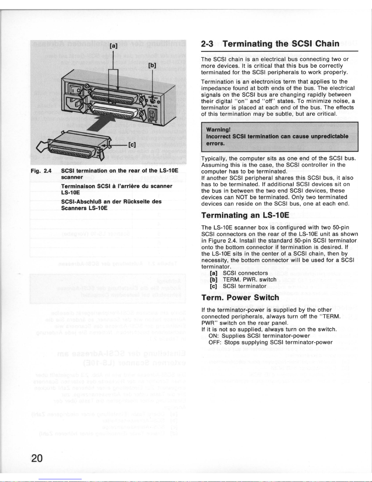
Fig. 2.4 SCSI termination
on
the rear of the LS-10E
scanner
20
Terminaison SCSI iI I'arriere
du
scanner
LS-10E
SCSI-AbschluB an der Ruckseite des
Scanners LS-10E
2-3 Terminating the SCSI Chain
The SCSI chain is an electrical bus connecting
two
or
more devices. It is critical that this bus be
correctly
terminated for the SCSI
peripherals
to
work
properly.
Termination is an electronics term
that
applies
to the
impedance found
at
both ends of the bus. The electrical
signals
on
the SCSI bus
are
changing
rapidly
between
their
digital "on" and " off" states. To
minimize
noise, a
terminator
is placed
at
each end of the bus. The effects
of this termination may be subtle, but are critical.
Warnlngl
Incorrect SCSI termination can cause unpredictable
errors.
Typically, the computer sits as one end of the SCSI bus.
Assuming this is the case, the SCSI
controller
in the
computer has to be terminated.
If another SCSI peripheral shares this SCSI bus, it also
has to be terminated. If additional SCSI devices sit on
the bus in between the two end SCSI devices, these
devices can NOT be terminated. Only two terminated
devices can reside on the SCSI bus , one
at
each end.
Terminating
an
LS-10E
The LS-10E scanner box is configured with two 50-pin
SCSI connectors on the
rear
of the LS-10E
unit
as shown
in Figure 2.4. Install the standard 50-pin SCSI
terminator
onto the bottom connector if
termination
is desired.
If
the LS-10E sits in the center of a SCSI chain , then by
necessity, the bottom connector
will
be used for a SCSI
terminator
.
[a] SCSI connectors
[b] TERM.
PWR.
switch
[c]
SCSI
terminator
Term. Power Switch
If the
terminator-power
is supplied by the
other
connected
peripherals
, always turn off the "TERM.
PWR
" switch on the
rear
panel.
If
it
is not so supplied , always turn on the switch.
ON
: Supplies SCSI
terminator-power
OFF: Stops supplying SCSI
terminator-power
2-3 Terminaison de la chaine SCSI
La chaine SCSI est un bus
electrique
reliant
deux
peripheriques
ou plus. Pour que les
peripheriques
SCSI
puissent
fonctionner
correctement, il est essentiel
que
la
terminaison
soit
correctement
effectuee.
"Terminaison
" est un
terme
d'electronique
qui
s'applique
a I'impedance
des
deux
extremites
du bus.
Les
signaux
electriques
sur
Ie bus SCSI passent
rapidement
entre
les
niveaux "
haut
" et
"bas
".
Pour
reduire
Ie
bruit
au
minimum,
une
terminaison
est placee
a chaque
extremite
du bus . Les effets
de
cette
terminaison
sont
essentiels.
AHentlonl
Une termlnalson SCSI Incorrecte peul provoquer des
erreurs Imprevlslbles.
Typiquement,
I'unite
centrale
se
trouve a I'une
des
extremites
du bus SCSI. Le contr61eur SCSI dans I'unite
centrale
est
alors
muni d'une
terminaison.
Si un autre
peripherique
SCSI partage ce bus SCSI, iI
do
it
lui aussi
recevoir
sa
terminaison
. Si
des
peripheriques
SCSI addition nels
se
trouvent
sur
Ie bus
entre
deux
peripheriques
, ces
peripheriques
NE
PEUVENT PAS
recevoir
de
terminaison
.
Autrement
dit, seules
deux
extremites
du bus SCSI
sont
munies
de
terminaisons.
Terminaison d'un LS-10E
Le
boitier
du scanner LS-10E com porte a
I'arriere
deux
connecteurs SCSI
de
50
broches, comme
Ie represente
la
figure
2.4. Installez Ie bouchon
de
terminaison
standard a 50
broches
sur
Ie
connecteur
inferieur
si une
terminaison
est necessaire . Si Ie
scanner
fait partie
d'une
chaine de
dispositifs
SCSI, Ie bouchon de
terminaison
sera
utilise
sur
Ie
dernier
dispositif.
[8] Connecteurs SCSI
[b]
Interrupteur
Term .
PWR
[c] Bouchon de
terminaison
SCSI
Interrupteur Term. Power
Si I'alimentation de la
terminaison
est
fournie
par
les
autres
peripheriques
, placez
I'interrupteur
"TERM.
PWR" situe
sur
Ie panneau
arriere
sur
OFF.
Si
elle
n'est pas
fournie
par
les
autres
peripheriques,
placez-Ie
sur ON.
ON
: Fournit
I'alimentation
de
terminaison
SCSI.
OFF: Coupe I'alimentation de
terminaison
SCSI.
2-3 AbschluB der SCSI-Kelle
Bei
der
SCSI-Kette handelt es sich um einen
elektrischen Bus zwischen zwei
oder
mehreren
Geraten.
Dieser
Bus muB auf jeden Fall entsprechend
terminiert
sein ,
damit
die
SCSI-Peripheriegerate einwandfrei
arbeiten k6nnen.
Bei
"AbschluB"
handelt es sich um einen elektronischen
Fachausdruck,
der
sich auf den Widerstand an beiden
Enden eines Busses bezieht. Die elektrischen Signale
auf
dem
SCSI-Bus wechseln in
schneller
Foige zwischen
dem
digitalen
EIN- und AUS-Zustand. Um
das
Rauschen
auf ein
Minimum
zu
verringern, wird
der
Bus an beiden
Enden abgeschlossen. Der Effekt eines solchen
Abschlusses mag
gering
sein,
er
ist
jedoch wichtig.
Achlungl
Falscher SCSI-AbschluB kann unvorhersehbare
Fehler verursachenl
Normalerweise
befindet sich
der
Computer an einem
Ende
des
SCSI-Busses. Sofern
dies
der
Fall ist, muB
der
SCSI-
Controller
im Computer
terminiert
werden .
Sollte ein
weiteres
SCSI-Peripheriegerat diesen SCSI-
Bus teilen, muB auch
dieses
abgeschlossen werden.
Befinden sich
weitere
SCSI-Gerate auf dem Bus
zwischen den beiden vorgenannten SCSI-Geraten,
so
k6nnen
diese
NICHT
terminiert
werden. Am SCSI-Bus
k6nnen sich
nur
zwei AbschluBschaltungen befinden,
eine
an
jedem
Ende.
AbschluB eines LS-10E
An
der
Ruckseite des LS-10E befinden sich -
wie
in Abb.
2.4
dargestellt
- zwei 50polige SCSI-Steckverbinder.
Bringen
Sie den normalen 50poligen SCSIAbschluBwiderstand gegebenenfalls im unteren
AnschluB an. Befindet sich
der
LS-10E in
der
Mitte
der
SCSI-Kette, ist
der
untere AnschluB zwangslaufig
mit
der
SCSI-Leitungsbrucke besetzt.
[8] SCSI-Stecker
[b] AbschluBstromschalter (TERM.
PWR)
[c] SCSI-AbschluBwiderstand
AbschluBstromschalter
Falls
der
AbschluBstrom
durch
die
anderen
angeschlossenen
Peripheriegerate
geliefert
wird
, stellen
Sie den AbschluBstromschalter (TERM .
PWR)
an
der
Ruckseite des Gerates grundsatzlich auf OFF (AUS).
Wird
der
Strom nicht so
geliefert
, stellen Sie den
Schalter stets auf
ON
(EIN).
ON
(EIN): SCSI-AbschluBstrom
wird
geliefert
OFF (AUS): SCSI-AbschluBstrom wird nicht
geliefert
21
[a]
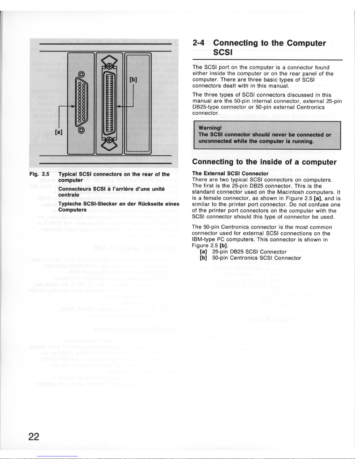
Fig. 2.5 Typical SCSI
connectors
on the
rear
of
the
computer
22
Connecteurs SCSI
Ii
I'arriere
d'une
unite
centrale
Typlsche SCSI-Stecker an
der
Riickseite
elnes
Computers
2-4 Connecting
to
the
Computer
SCSI
The SCSI
port
on the
computer
is a connector found
either
inside the
computer
or
on the
rear
panel of the
computer. There
are
three basic types of SCSI
connectors
dealt
with in
this
manual.
The
three
types of SCSI connectors discussed in this
manual
are
the
SO-pin
internal
connector
, external 2S-pin
OB2S-type
connector
or
SO-pin
external Centronics
connector.
Warnlngl
The SCSI
connector
should
never
be
connected
or
unconnected
while
the
computer
Is
running.
Connecting to
the
inside
of a computer
The External SCSI
Connector
There
are
two
typical SCSI connectors on
computers
.
The
first
is the 2S-pin
OB2S
connector
. This is the
standard
connector
used on the Macintosh computers. It
is a female
connector
, as shown in
Figure
2.S
[a]
, and is
similar
to the
printer
port
connector. 00
not confuse one
of the
printer
port
connectors on the
computer
with the
SCSI connector should this type
of
connector
be used .
The
SO-pin
Centronics connector is the most
common
connector used
for
external SCSI connections on the
IBM-type
PC
computers. This
connector
is shown in
Figure
2.S
[b].
[a]
2S-pin
OB2S
SCSI
Connector
[b] SO-pin Centronics SCSI
Connector

2-4 Connexion SCSI a I'unite
centrale
Le
port
SCSI
de I'ord inateur est un connecteur situe
it
I'
interieur
ou
sur
Ie panneau
arriere
de
I'unite centrale.
Ce manuel traite de trois types de connecteurs SCSI.
Trois types differents
de
connecteurs SCSI nous
interessent
pour
Ie raccordement du scanner:
50
broches en ligne (internes) ,
25
broches OB-
25
et
50
broches Centronics (externes).
Attentlonl
Ne
branchez et ne debranchez jamals un connecteur
SCSI pendant Ie lonctlonnement de I'unlte centrale.
Connexion
it
I'interieur
de
I'unite
centrale
Connecteur SCSI externe
Les unites centrales peuvent etre munies
de
deux types
de connecteurs SCSI. Le
premier
est Ie connecteur
OB25
it
25
broches qui est
Ie
connecteur standard des
Macintosh. C'est un connecteur
femelle
tel que Ie
represente la
figure
2.5
[a]
similaire
au
connecteur du
port
d'imprimante.
II
faut donc
veiller
it ne pas Ie
confondre avec les ports d'
impr
imante
de
I'unite
centrale.
Le connecteur Centronics
it
50
broches est Ie
connecteur
Ie
plus communement
utilise
pour
les
connexions SCSI externes
sur
les ordinateurs de type
IBM
PC.
Ce
connecteur est represente
it
la
figure 2.5 [b].
[a] connecteur
25
broches OB-25
[b] connecteur
50
broches Centronics SCSI
2-4 AnschluB an die SCSI-
Schnittstelle des Computers
Oer SCSI-Anschlu'B des Computers befindet sich
entweder im Inneren
oder
an dessen Ruckseite.
In
diesem Handbuch werden drei Grundtypen von
SCSI
-
Steckverbindern behandelt.
Bei den drei in diesem Handbuch besprochenen
SCSI
-
Steckverbindern handelt es sich um den 50poligen
Innensteckverbinder, den 25poligen
AuBensteckverbinder
0825
und den 50poligen
Centronics-AuBensteckverbinder.
Achtungl
Schneeen Sle den SCSI-Steckverblnder nle bel
laufendem Computer ani
AnschluB
im
Innern
des
Computers
Der auBere SCSI-Steckverbinder
Es
gibt zwei typische SCSI-Steckverbinder an
Computern . Oer erste ist
der
25polige OB25-
Steckverbinder. Oies ist
der
Standard-Steckverbi
nder
an
Macintosh-Computern.
Es
ist eine Steckerbuchse (siehe
Abb . 2.5
[a]). die dem OruckeranschluB ahnelt.
Verwechseln Sie keinesfalls einen
der
Oruckeranschlusse des Computers mit dem SCSISteckverbinder!
Oer 50polige Centronics-Steckverbinder ist
der
gebrauchlichste Steckverbinder
fUr
auBere SCSI-
Anschlusse an IBM-kompatiblen PCs. Er ist in Abb. 2.5
[b] dargestellt.
[a] 25poliger SCSI-Steckverbinder
0825
[b] 50poliger SCSI-Steckverbinder von Centronics
23
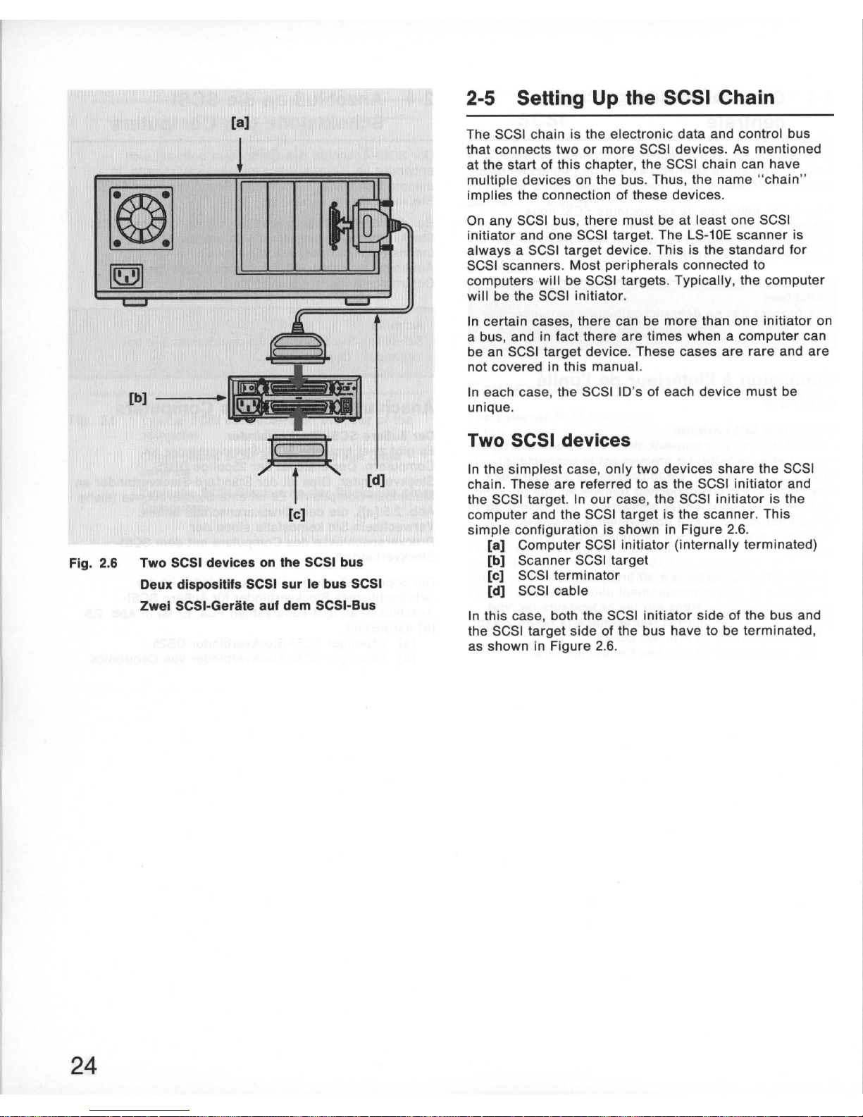
Fig. 2.6
24
[a]
[b)
---llii.im
Ic::::JI
./
f
'"
[d)
[e)
Two SCSI devices
on
the SCSI bus
Deux dlspositifs SCSI sur Ie bus SCSI
Zwel SCSI·Geriite auf dem SCSI·Bus
2-5 SeHing Up the SCSI Chain
The SCSI chain is the
electronic
data and control bus
that connects
two
or
more
SCSI
devices
. As mentioned
at
the
start
of this chapter, the SCSI chain can have
multiple
devices on the bus . Thus, the
name
"chain "
implies
the connection of these
devices
.
On any SCSI bus,
there
must be at
least
one SCSI
initiator
and one SCSI target. The LS-10E
scanner
is
always
a SCSI
target
device
. This is the standard
for
SCSI
scanners. Most
peripherals
connected to
computers
will
be SCSI
targets. Typically
, the
computer
will
be the SCSI
initiator
.
In certain cases ,
there
can be
more
than one
initiator
on
a bus, and in fact
there
are
times
when a
computer
can
be an SCSI
target
device. These cases
are
rare
and
are
not covered in
this
manual.
In each case , the SCSI ID's of each
device
must
be
unique.
Two SCSI devices
In the
simplest
case,
only
two
devices
share
the SCSI
chain. These
are
referred to as the SCSI
initiator
and
the SCSI target. In
our
case,
the
SCSI
initiator
is the
computer
and the SCSI
target
is the scanner. This
simple
configuration is shown in
Figure
2.6.
[a]
Computer
SCSI
initiator
(internally
terminated)
[b] Scanner SCSI
target
[c] SCSI
terminator
[d] SCSI cable
In this case , both the SCSI
initiator
side
of
the
bus
and
the SCSI
target
side
of the
bus
have to be terminated,
as shown in Figure 2.6.
2-5 Etablissement de la chaine
SCSI
La chaine SCSI est un bus de donnees electroniques
et
de commande
reliant
deux
peripMriques
SCSI ou plus.
Comme il a ete indique au debut du chapitre, la chaine
SCSI peut
comporter
plusieurs
dispositifs
sur
Ie bus. Le
terme "chaine"
designe la liaison
de
ces peripheriques.
Sur
un bus SCSI,
iI
doit y avoir
au moins un maitre SCSI
et
un esclave SCSI. Le
scanner
LS-10E est toujours un
esclave SCSI. C'est la
norme
pour
les scanners SCSI.
La
plupart
des
peripMriques
relies a I'unite centrale
sont des esclaves SCSI. L'unite centrale est
generalement
Ie
maitre
SCSI.
Dans certains cas, il peut
y
avoir
plusieurs
maitres
sur
un bus ; parfois, I'unite centrale peut etre un esclave
SCSI. Ces cas
sont
rares et ne sont pas traites dans
Ie
present manuel.
Dans tous les cas, la regie
a respecter absolument est
I'attribution
a chaque
dispositif
d'une
10
SCSI unique.
Deux dispositifs SCSI
Dans Ie cas
Ie
plus
simple, seulement
deux dispositifs
SCSI constituent la chaine . lis sont designes comme
maitre et esclave. Dans Ie cas
traite
I'unite centrale est
Ie
maitre
et
Ie
scanner
, I'esclave. Cette fa«on tres
simple
d'interfacer deux dispositifs est
montree
figure
2.6.
[8] Unite centrale
Maitre
SCSI (terminaison
interieure)
[b] Scanner Esclave SCSI
[c] Terminaison SCSI (bouchon)
[d] Cable SCSI
Dans ce cas, les deux extremites du bus SCSI doivent
recevoir
une terminaison, comme indique
sur
la
figure
2.6.
2-5 Aufbau der SCSI-KeHe
Bei
der
SCSI-Kette handelt es sich urn den
elektronischen Daten- und Steuerbus ,
der
zwei oder
mehr
SCSI-Gerate verbindet. Wie bereits zu Beginn
dieses Kapitels erwahnt, kiinnen sich innerhalb
der
SCSI-Kette
mehrere
Gerate auf dem Bus befinden . Somit
bezieht sich
die
Bezeichnung
"Kette
" auf
die
Verbindung
dieser
Gerate.
Auf jedem SCSI-Bus
muB
sich mindestens ein SCSIHauptgerat und ein SCSI-Nebengerat befinden. Der
Scanner LS-10E ist stets das SCSI-Nebengerat. Dies ist
normal
fOr
SCSI-Scanner. Bei den meisten an einen
Computer angeschlossenen Peripheriegeraten handelt
es sich urn SCSI-Nebengerate.
1m
Normalfall ist
der
Computer das SCSI-Hauptgerat.
In
manchen Fallen kann sich
mehr
als ein Hauptgerat
auf einem Bus befinden, und es kann auch vorkommen ,
daB ein Computer zum SCSI-Nebengerat wird. Dies ist
jedoch
nur
selten
der
Fall, so daB
hier
nicht darauf
eingegangen
wird
.
In
jedem
Fall
darf
die SCSI-Adresse jedes Gerats nur
einmal vergeben sein.
Zwei SCSI-Gerate
1m
einfachsten Fall befinden sich
nur
zwei Gerate in
der
SCSI-Kette. Diese gelten als SCSI-Hauptgerat und SCSI-
Nebengerat.
In
unserem Fall ist das SCSI-Hauptgerat
der
Computer und das SCSI-Nebengerat
der
Scanner.
Diese einfache Anordnung ist in Abb . 2.6 dargestellt.
[8] Computer, SCSI-Hauptgerat (intern
abgeschlossen)
[b] Scanner, SCSI-Nebengerat
[c] SCSI-AbschluB
[d] SCSI-Kabel
In
diesem
Fall
muB
der
Bus sowohl auf
der
Seite des
SCSI-Hauptgerats als auch auf
jener
des SCSI-
Nebengerats
terminiert
werden. Dies ist in Abb. 2.6
dargestellt.
25
 Loading...