

Nikon Coolpix L3 Service manual
VAA59004-R.3687.A
作成承認印 配布許可印
VAA59004(Silver)
VAA59214(White)
VAA59424(Black)
VAA59524(Blue)
REPAIR MANUAL
Printed in Japan February 2006
Copyright c 2006 by Nikon Corporation.
All Rights Reserved.
無断転載を禁ず
!!

VAA59004-R.3687.A
CONTENTS
SPECIFICATIONS ・・・・・・・・・・・・・・・・・・・・・・・・・・・・・・・・・・・・・・・・・・・・・・・・・・・・・・・・・・・・・・・・・・・・・・・・・・・ M1~2
DISASSEMBLY
WARNING ・・・・・・・・・・・・・・・・・・・・・・・・・・・・・・・・・・・・・・・・・・・・・・・・・・・・・・・・・・・・・・・・・・・・・・・・・・・・・・・・・・D1
REMOVAL OF REAR COVER ・・・・・・・・・・・・・・・・・・・・・・・・・・・・・・・・・・・・・・・・・・・・・・・・・・・・・・・・・・・・ D2-D3
DISCHARGING OF MAIN CONDENSER ・・・・・・・・・・・・・・・・・・・・・・・・・・・・・・・・・・・・・・・・・・・・・・・・・・・・・・・・D4
REMOVAL OF LCD ・・・・・・・・・・・・・・・・・・・・・・・・・・・・・・・・・・・・・・・・・・・・・・・・・・・・・・・・・・・・・・・・・・・・・・・・・・ D5
REMOVAL OF MONITOR HOLDER ・・・・・・・・・・・・・・・・・・・・・・・・・・・・・・・・・・・・・・・・・・・・・・・・・・・・・・・・・・・・ D6
REMOVAL OF FRONT COVER ・・・・・・・・・・・・・・・・・・・・・・・・・・・・・・・・・・・・・・・・・・・・・・・・・・・・・・・・・・・・・・・・D6
REMOVAL OF SPEAKER ・・・・・・・・・・・・・・・・・・・・・・・・・・・・・・・・・・・・・・・・・・・・・・・・・・・・・・・・・・・・・・・・・・・・・ D7
REMOVAL OF TB-1 PCB UNIT ・・・・・・・・・・・・・・・・・・・・・・・・・・・・・・・・・・・・・・・・・・・・・・・・・・・・・・・・・・・・・・・・ D8
REMOVAL OF FLASH HOLDER ・・・・・・・・・・・・・・・・・・・・・・・・・・・・・・・・・・・・・・・・・・・・・・・・・・・・・・・・・・・・・・・ D9
DISASSEMBLY OF FLASH UNIT ・・・・・・・・・・・・・・・・・・・・・・・・・・・・・・・・・・・・・・・・・・・・・・・・・・・・・・・・・・・・ D10
REMOVAL OF LENS UNIT ・・・・・・・・・・・・・・・・・・・・・・・・・・・・・・・・・・・・・・・・・・・・・・・・・・・・・・・・・・・・・・・・・・ D10
REMOVAL OF BATTERY COVER ・・・・・・・・・・・・・・・・・・・・・・・・・・・・・・・・・・・・・・・・・・・・・・・・・・・・・・・・・・・・ D11
DISASSEMBLY OF REAR COVER ・・・・・・・・・・・・・・・・・・・・・・・・・・・・・・・・・・・・・・・・・・・・・・・・・・・・・・・・・・・ D12
REMOVAL OF TRIPOD SOCKET ・・・・・・・・・・・・・・・・・・・・・・・・・・・・・・・・・・・・・・・・・・・・・・・・・・・・・・・・・・・・・ D13
REMOVAL OF HOLDER LENS ・・・・・・・・・・・・・・・・・・・・・・・・・・・・・・・・・・・・・・・・・・・・・・・・・・・・・・・・・・・・・・D13
REMOVAL OF BATTERY HOLDER ・・・・・・・・・・・・・・・・・・・・・・・・・・・・・・・・・・・・・・・・・・・・・・・・・・・・・・・・・・・D14
REMOVAL OF MICROPHONE ・・・・・・・・・・・・・・・・・・・・・・・・・・・・・・・・・・・・・・・・・・・・・・・・・・・・・・・・・・・・・・・ D15
DISASSEMBLY OF FRONT COVER ・・・・・・・・・・・・・・・・・・・・・・・・・・・・・・・・・・・・・・・・・・・・・・・・・・・・・・・・・・ D15
REMOVAL OF CCD MOUNT ・・・・・・・・・・・・・・・・・・・・・・・・・・・・・・・・・・・・・・・・・・・・・・・・・・・・・・・・・・・・・・・・ D16
DISASSEMBLY OF CCD MOUNT GEAR UNIT ・・・・・・・・・・・・・・・・・・・・・・・・・・・・・・・・・・・・・・・・・・・・・・・・・ D17
REMOVAL OF FIXED BARREL ・・・・・・・・・・・・・・・・・・・・・・・・・・・・・・・・・・・・・・・・・・・・・・・・・・・・・・・・・・・・・・ D18
REMOVAL OF ROTARY BARREL UNIT ・・・・・・・・・・・・・・・・・・・・・・・・・・・・・・・・・・・・・・・・・・・・・・・・・・・・・・ D18
ASSEMBLY
INSTALLATION OF ROTARY BARREL UNIT ・・・・・・・・・・・・・・・・・・・・・・・・・・・・・・・・・・・・・・・・・・・・・・・・・・・ A 1
INSTALLATION OF FIXED BARREL ・・・・・・・・・・・・・・・・・・・・・・・・・・・・・・・・・・・・・・・・・・・・・・・・・・・・・・・・・・・ A1
ASSEMBLY OF CCD MOUNT GEAR UNIT ・・・・・・・・・・・・・・・・・・・・・・・・・・・・・・・・・・・・・・・・・・・・・・・・ A 2-A3
INSTALLATION OF CCD MOUNT ・・・・・・・・・・・・・・・・・・・・・・・・・・・・・・・・・・・・・・・・・・・・・・・・・・・・・・・・・・・・・ A 4
MAKING OF THE LENS BARREL DRIVE TOOL ・・・・・・・・・・・・・・・・・・・・・・・・・・・・・・・・・・・・・・・・・・・・・・・・・ A5
ASSEMBLY OF FRONT COVER ・・・・・・・・・・・・・・・・・・・・・・・・・・・・・・・・・・・・・・・・・・・・・・・・・・・・・・・・・・・・・・・A 6
ASSEMBLY OF BATTERY HOLDER ・・・・・・・・・・・・・・・・・・・・・・・・・・・・・・・・・・・・・・・・・・・・・・・・・・・・・・ A 7-A8
ASSEMBLY OF LENS HOLDER ・・・・・・・・・・・・・・・・・・・・・・・・・・・・・・・・・・・・・・・・・・・・・・・・・・・・・・・・・・・・・・・ A 8
ASSEMBLY OF FRONT COVER ・・・・・・・・・・・・・・・・・・・・・・・・・・・・・・・・・・・・・・・・・・・・・・・・・・・・・・・ A 9-A13
ASSEMBLY OF LENS UNIT ・・・・・・・・・・・・・・・・・・・・・・・・・・・・・・・・・・・・・・・・・・・・・・・・・・・・・・・・・ A 13-A14
- L3 -

VAA59004-R.3687.A
ASSEMBLY OF FLASH UNIT ・・・・・・・・・・・・・・・・・・・・・・・・・・・・・・・・・・・・・・・・・・・・・・・・・・・・・・・・・ A 15-16
ASSEMBLY OF TB-1 PCB UNIT ・・・・・・・・・・・・・・・・・・・・・・・・・・・・・・・・・・・・・・・・・・・・・・・・・・・・・・・・・・・・・ A 16
ASSEMBLY OF SPEAKER ・・・・・・・・・・・・・・・・・・・・・・・・・・・・・・・・・・・・・・・・・・・・・・・・・・・・・・・・・・・・・・・・・・ A 17
ASSEMBLY OF TRIPOD SOCKET ・・・・・・・・・・・・・・・・・・・・・・・・・・・・・・・・・・・・・・・・・・・・・・・・・・・・・・・・・・・・ A 18
ASSEMBLY OF EARTH SHAFT ・・・・・・・・・・・・・・・・・・・・・・・・・・・・・・・・・・・・・・・・・・・・・・・・・・・・・・・・・・・・・・ A 18
ADHESION OF EARTH UNIT ・・・・・・・・・・・・・・・・・・・・・・・・・・・・・・・・・・・・・・・・・・・・・・・・・・・・・・・・・・・・・・・・ A 18
ASSEMBLY OF FRONT COVER ・・・・・・・・・・・・・・・・・・・・・・・・・・・・・・・・・・・・・・・・・・・・・・・・・・・・・・・・・・・・・ A 19
ASSEMBLY OF MONITOR HOLDER ・・・・・・・・・・・・・・・・・・・・・・・・・・・・・・・・・・・・・・・・・・・・・・・・・ A20-A23
ASSEMBLY OF LCD ・・・・・・・・・・・・・・・・・・・・・・・・・・・・・・・・・・・・・・・・・・・・・・・・・・・・・・・・・・・・・・・ A23-A24
ASSEMBLY OF REAR COVER ・・・・・・・・・・・・・・・・・・・・・・・・・・・・・・・・・・・・・・・・・・・・・・・・・・・・・・・ A24-A26
REPLACEMENT OF LENS BARRIER UNIT ・・・・・・・・・・・・・・・・・・・・・・・・・・・・・・・・・・・・・・・・・・・・ A27-A30
ADJUSTMENT ・・・・・・・・・・・・・・・・・・・・・・・・・・・・・・・・・・・・・・・・・・・・・・・・・・・・・・・・・・・・・・・・・・・・・・・A31-E40
DISCRIPTION OF CIRCUIT ・・・・・・・・・・・・・・・・・・・・・・・・・・・・・・・・・・・・・・・・・・・・・・・・・・・・・・・・・・・・・・・・・ E1-E8
ELECTRICITY
OVERALL WIRING ・・・・・・・・・・・・・・・・・・・・・・・・・・・・・・・・・・・・・・・・・・・・・・・・・・・・・・・・・・・・・・・・・・・・・・・・・・ E9
CP1(DMA) CIRCUIT DIAGRAM ・・・・・・・・・・・・・・・・・・・・・・・・・・・・・・・・・・・・・・・・・・・・・・・・・・・・・・・・・・・・・ E10
CP1(CAA) CIRCUIT DIAGRAM ・・・・・・・・・・・・・・・・・・・・・・・・・・・・・・・・・・・・・・・・・・・・・・・・・・・・・・・・・・・・・・ E11
CP1(PWA) CIRCUIT DIAGRAM ・・・・・・・・・・・・・・・・・・・・・・・・・・・・・・・・・・・・・・・・・・・・・・・・・・・・・・・・・・・・・・ E12
CP1(STA) CIRCUIT DIAGRAM ・・・・・・・・・・・・・・・・・・・・・・・・・・・・・・・・・・・・・・・・・・・・・・・・・・・・・・・・・・・・・・ E13
CP1(SYA) CIRCUIT DIAGRAM ・・・・・・・・・・・・・・・・・・・・・・・・・・・・・・・・・・・・・・・・・・・・・・・・・・・・・・・・・・・・・・ E14
TB1 CIRCUIT DIAGRAM ・・・・・・・・・・・・・・・・・・・・・・・・・・・・・・・・・・・・・・・・・・・・・・・・・・・・・・・・・・・・・・・・・・・ E15
OVERALL BLOCK DIAGRAM ・・・・・・・・・・・・・・・・・・・・・・・・・・・・・・・・・・・・・・・・・・・・・・・・・・・・・・・・・・・・・・・ E16
CCD BLOCK DIAGRAM ・・・・・・・・・・・・・・・・・・・・・・・・・・・・・・・・・・・・・・・・・・・・・・・・・・・・・・・・・・・・・・・・・・・・ E17
LENS BLOCK DIAGRAM ・・・・・・・・・・・・・・・・・・・・・・・・・・・・・・・・・・・・・・・・・・・・・・・・・・・・・・・・・・・・・・・・・・・ E18
ASIC BLOCK DIAGRAM ・・・・・・・・・・・・・・・・・・・・・・・・・・・・・・・・・・・・・・・・・・・・・・・・・・・・・・・・・・・・・・・・・・・ E19
SYSTEM CONTROL BLOCK DIAGRAM ・・・・・・・・・・・・・・・・・・・・・・・・・・・・・・・・・・・・・・・・・・・・・・・・・・・・・・ E20
POWER BLOCK DIAGRAM ・・・・・・・・・・・・・・・・・・・・・・・・・・・・・・・・・・・・・・・・・・・・・・・・・・・・・・・・・・・・・・・・・ E21
FUSE arrangement (CP1 PCB) ・・・・・・・・・・・・・・・・・・・・・・・・・・・・・・・・・・・・・・・・・・・・・・・・・・・・・・・・・・・・・・・・ E22
INSPECTION STANDARDS ・・・・・・・・・・・・・・・・・・・・・・・・・・・・・・・・・・・・・・・・・・・・・・・・・・・・・・・・・・・・・・・R1-R10
Tool List ・・・・・・・・・・・・・・・・・・・・・・・・・・・・・・・・・・・・・・・・・・・・・・・・・・・・・・・・・・・・・・・・・・・・・・・・・・・・・・・・・ T1-T2
- L3 -

SPECIFICATIONS
Type Compact digital camera
Effective pixels 5.1 million
VAA59004-R.3687.A
CCD
Image size(pixels)
Lens
Focal length
f/-number
Construction
Digital zoom Up to 4 × (35-mm [135] camera-format equivalent: 450mm)
Autofocus (AF)
Focus range(from lens)
Focus-area selection
Monitor
Approximate frame coverage
Storage
Media
1/2.5-in. CCD; total pixels: 5.36 million
・ 2,592 × 1,944 (2592*, 2592) ・ 2,048 × 1,536 (2048)
・ 1,024 × 768 (1024) ・ 640 × 480 (640)
Zoom-Nikkor with 3 × optical zoom
F=6.3-19.2mm (35-mm [135] camera-format equivalent: 38-116mm)
f/3.2-/f5.3
5 elements in 5 groups
Contrast-detect AF
30cm (1ft.) - ∞
Macro close-up mode: 10cm (3.9in.) - ∞ (W)
Center
2in., 86,000-dot, TFT LCD monitor with brightness adjustment
Shooting mode: 97% horizontal and 97% vertical
Playback: 100% horizontal and 100% vertical
Internal memory (approx.23MB); SD (Secure Digital) memory cards
File system
File formats
Exposure
Metering
Exposure control
Range
Shutter
Speed
Aperture
Range
ISO sensitivity
(Recommended Exposure
Index)
Self-timer Approximately 10 seconds
Built-in flash
DCF, Exif 2.2, and DPOF compliant
Compressed: JPEG-baseline-compliant
Movies: QuickTime Sound files: WAV
Matrix, center-weighted
Programmed auto exposure with exposure compensation
(-2.0 ~ +2.0EV in steps of 1/3EV)
W: +2.5 ~ +16.0EV T: +4.1 ~ +17.5EV
Mechanical and charge-coupled electronic shutter
4-1/1500s
Magnetically controlled
f/3.2 and f/6.4 (W)
Approximately equivalent to ISO 50 (auto gain to ISO 200)
Range (approx.)
Sync method
I/O terminals Audio video out/digital IO (USB)
W: 0.3 ~ 3.0m/1ft. ~ 9ft. 10in. T: 0.3 ~ 1.75m/1ft. ~ 5ft. 9in.
Sensor flash system
- M1・ L3 -

VAA59004-R.3687.A
Video output Can be selected from NTSC and PAL
Supported languages Chinese (Simplified and Traditional), Dutch, English, French, German, Italian, Japanese,
Korean, Russian, Spanish, Swedish
Power sources ・ Two AA alkaline, oxyride, or lithium batteries
・ Two rechargeable EN-MH1 NiMH batteries
・ EH-65A AC adapter kit
Battery life Approximately 200 shots with alkaline, 630 shots with lithium, or 330 shots with
EN-MH1 batteries*
Approximate dimensions 91 × 60.5 × 26mm/3.6 × 2.4 × 1in. (W × H × D)
Approximate weight 120g (4.2oz.) without battery or memory card
Operating environment
Temperature
Humidity
* Based on Camera and Imaging Products Association (CIPA) standard for measuring life of camera batteries. Measured at
25°C (77°F); zoom adjusted with each shot, flash fired with every other shot, image mode set to NORMAL.
0 ~ +40°C (+32 ~°F104)
Less than 85% (no condensation)
- M2・ L3 -
DISASSEMBLY
WARNING
There are high voltege parts inside. Be careful of this electric shock,
when you remove the cover.
Yo
u must discharge the main condenser according to the instruction
of this repair manual after you remove the cover
.
!
・ Lead-free solder is used for this product.
・ For soldering work, the special solder and soldering iron are required.
・ Do NOT mix up lead-free solder with traditional solder.
・ Use the special soldering iron respectively for lead-free solder and lead solder. They cannot be used in
common.
VAA59004-R.3687.A
Points to notice for Lead-free solder products
Note : ① Be sure to remove the SD memory card and batteries before disassembly.
② When disassembling, make sure to memorize the processing state of wires, screws to be
fixed and their types, etc.
③ Because electrical parts are easily damaged by static electricity, make sure that you are
well earthed/grounded.
- D1 ・ L3 -

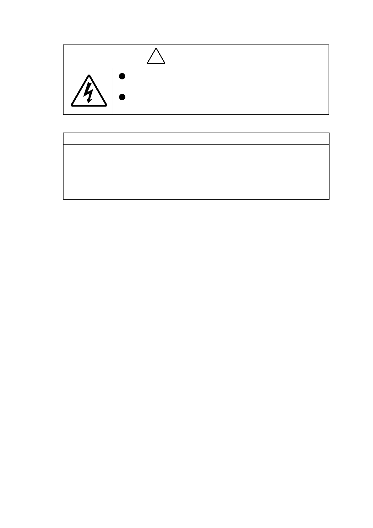
REMOVAL OF REAR COVER
・ Remove the four screws [#101]
Screw
VAA59004-R.3687.A
[#101]
Screw [#101]
・ Remove the screw [#102].
・
Remove the screw [#103].
・ Remove the screw [#107].
Screw [#101]
Screw [#101]
Screw [#103]
Screw [#102]
Screw
[#107]
- D2 ・ L3 -
・
Unhook in the order of ① to ③ to remove the rear cover [#022].
①
Rear cover [#022]
Rear cover [#022]
②
VAA59004-R.3687.A
Hook
Hook
③
Hook
Be careful not to catch the multi-connecter terminal.
- D3 ・ L3 -
Rear cover [#022]

VAA59004-R.3687.A
WARNING
There are high voltege parts inside. Be careful of this electric shock,
when you remove the cover.
Yo
u must discharge the main condenser according to the instruction
of this repair manual after you remove the cover
.
!
DISCHARGING OF MAIN CONDENSER
Push the terminal onto the solder section of the lead wire [Pink] and onto the whole surface of the earth plate [#012], and
discharge the condenser.
Earth plate [#012]
Lead wire [Pink]
2K Ω /5W
- D4 ・ L3 -

REMOVAL OF LCD
・ Remove the LCD UNIT [#008] from the hooks.
Hook
VAA59004-R.3687.A
・ Remove the FPC.
・ Unsolder the lead wires [Black] and [Red].
LCD UNIT[#008]
Lead wires [Black] and [Red]
FPC
- D5 ・ L3 -
REMOVAL OF MONITOR HOLDER
・ Turn up the spacer [#011] and remove the screw [#104].
・ Remove the earth contact [#004].
VAA59004-R.3687.A
Earth plate [#012]
・ Remove the three screws [#105] .
・ Remove the earth plate [#012].
・ Remove the monitor holder [#003].
Screw[#105]
Screw [#105]
Screw [#105]
Monitor holder [#003]
Screw [#104]
Earth contact [#004]
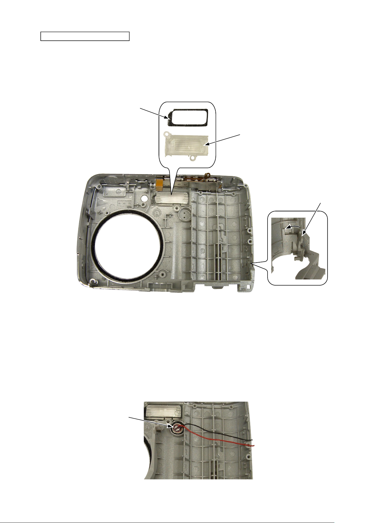
REMOVAL OF FRONT COVER
・ Unsolder the lead wires [Black] and [Red] of the microphone [#223].
・ Unsolder the lead wires [Black] and [Red] of the speaker [#227].
・
Unsolder the lead wires [Gray] and [White] of the TB-1 PCB unit [#221].
・ Remove the spacer [#237].
Lead wires [Gray] and [White] of
Lead wires [Black] and
[Red] of speaker [#227]
TB-1 PCB unit [#221]
Lead wires [Black] and
[Red] of microphone [#223]
Spacer[#237]
- D6 ・ L3 -
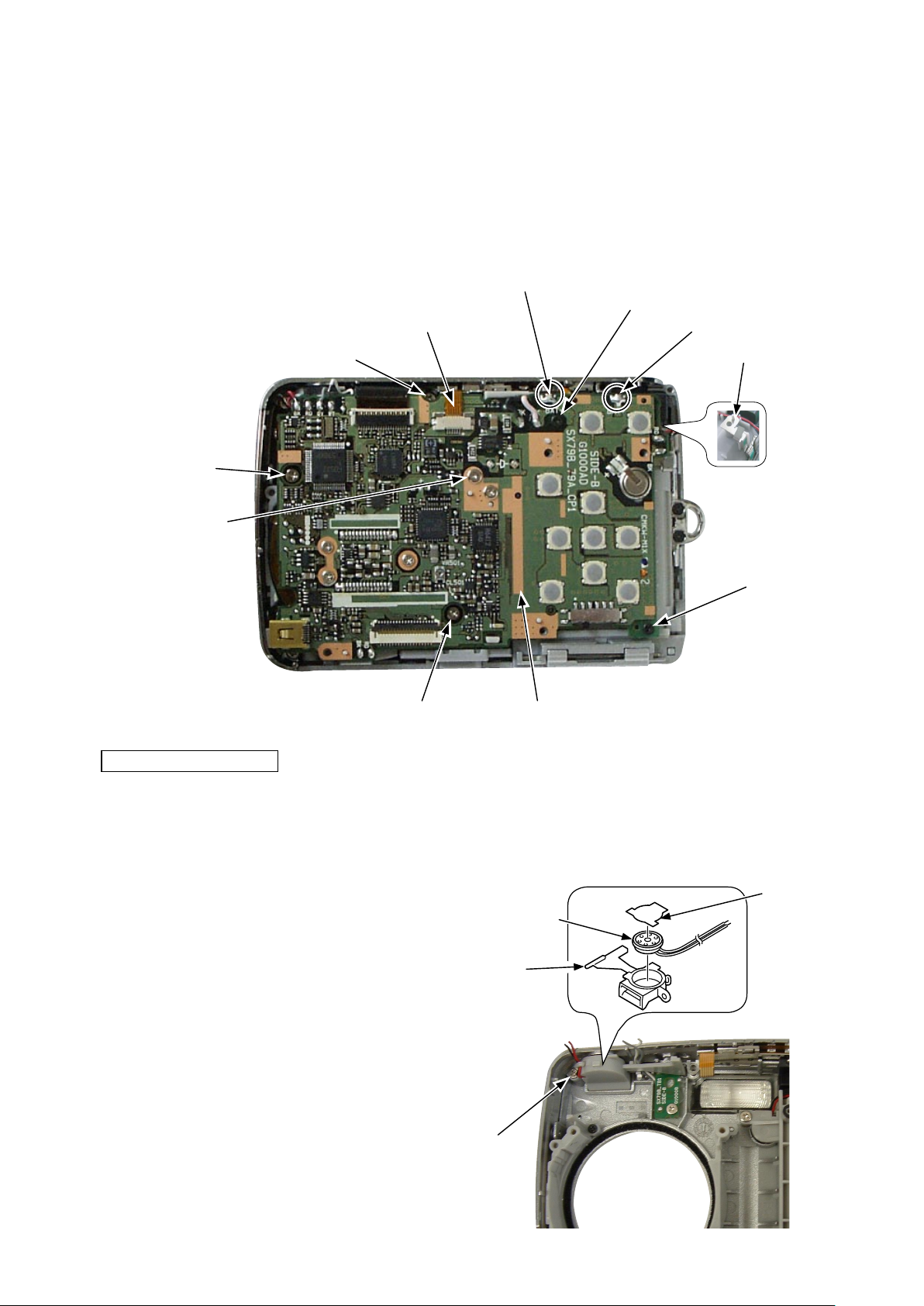
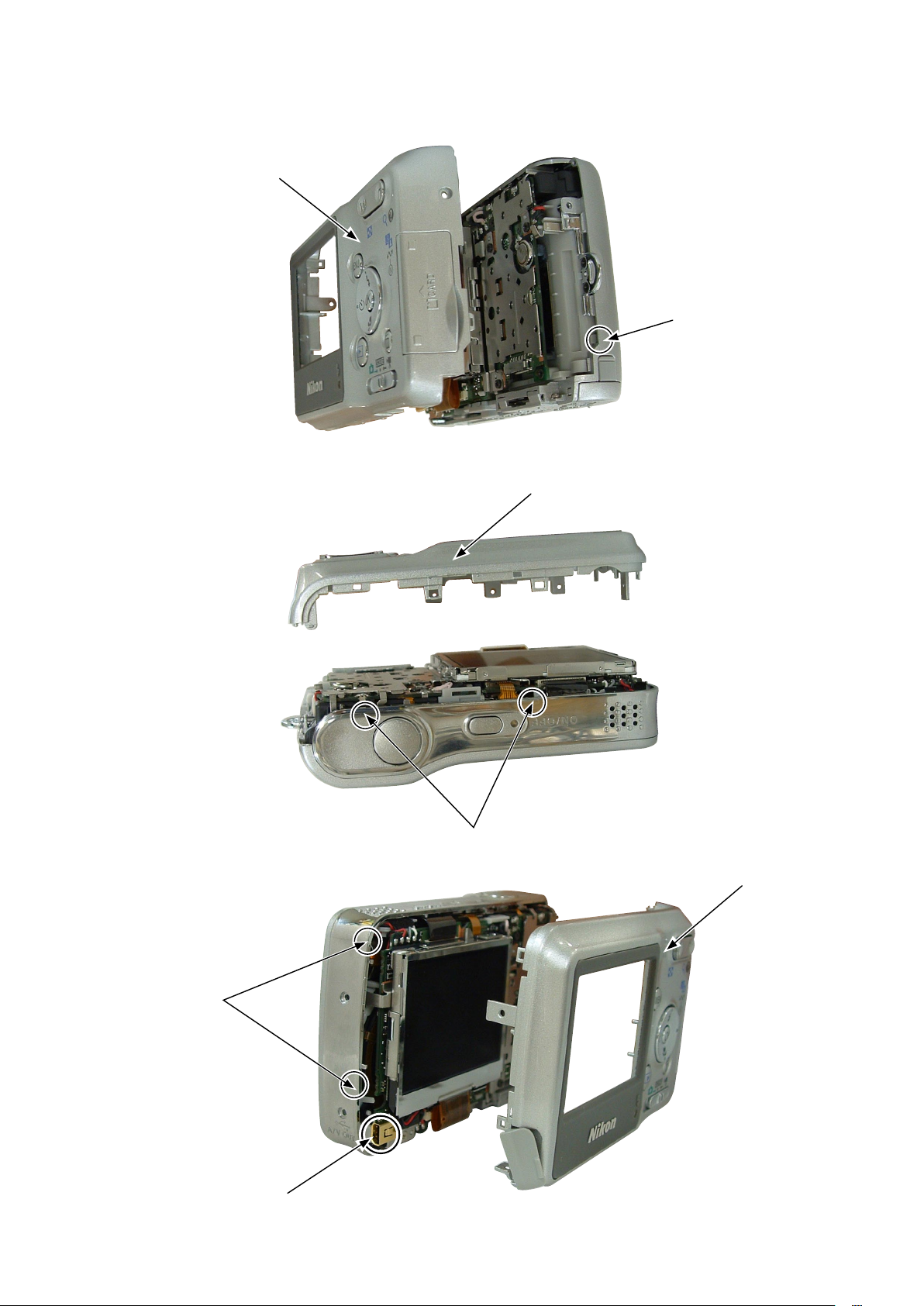
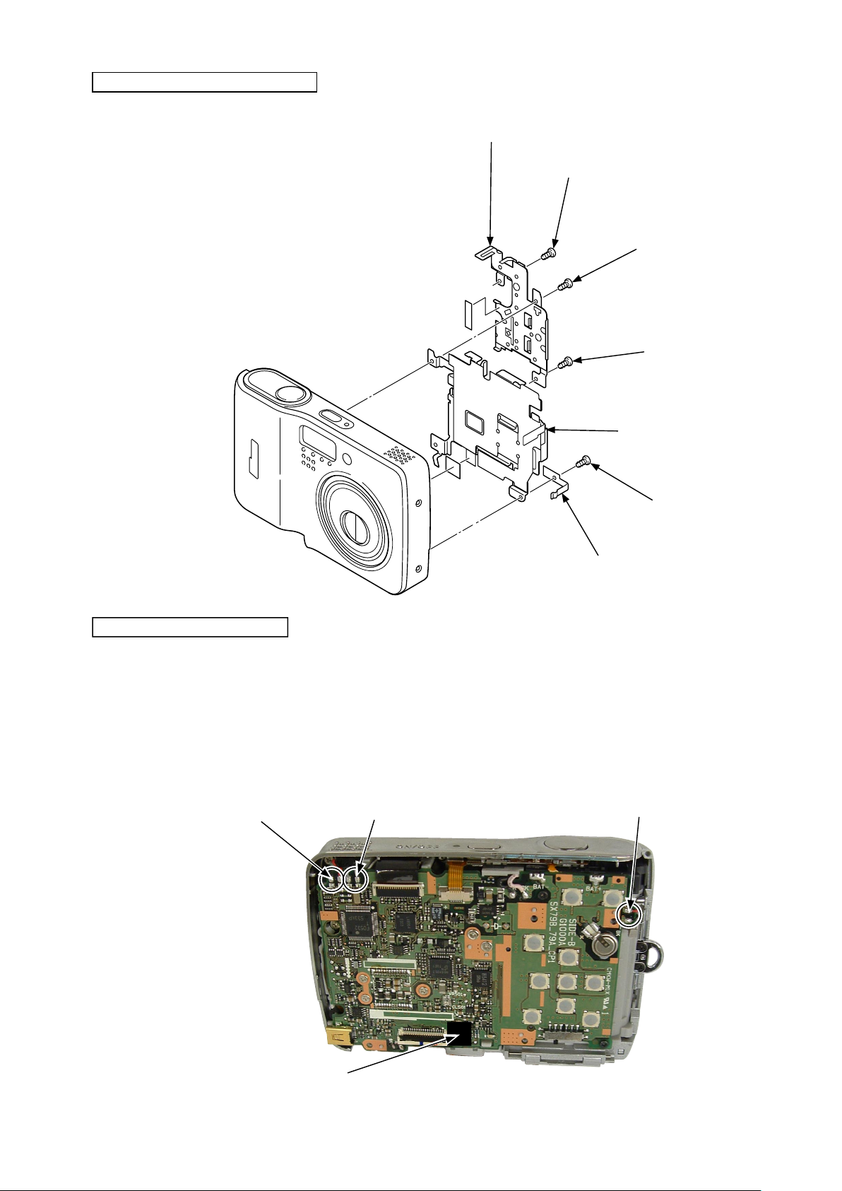
・ Remove the special screw [#109].
・ Remove the three screws [#104].
・ Remove the two screws [#105] .
・ Unsolder "BAT-" and "BAT+".
・ Remove the FPC.
・ Remove the main PCB unit CP-1 [#238].
・ Remove the earth contact [#218].
VAA59004-R.3687.A
Screw [#104]
Screw [#104]
Screw [#109]
Screw [#104]
FPC
BAT-
Main PCB unit CP-1 [#238]
Screw [#105]
BAT+
Earth contact [#218]
Screw [#105]
REMOVAL OF SPEAKER
・ Remove the screw [#109].
・ Remove the holder speaker [#226].
・ Take off the spacer [#228].
・ Remove the speaker [#227].
Spacer [#228]
Speaker [#227]
Holder speaker [#226]
Screw [#109]
- D7 ・ L3 -

REMOVAL OF TB-1 PCB UNIT
・ Remove the screw [#110].
・ Remove the TB-1 PCB unit [#221].
・ Remove the self window [#222] from the front cover [#207].
TB-1 PCB unit [#221]
VAA59004-R.3687.A
Self window [#222]
Screw [#110]
- D8 ・ L3 -

REMOVAL OF FLASH HOLDER
・ Unsolder the lead wires [Pink] and [Black].
VAA59004-R.3687.A
Lead Wire Wires [Pink] and [Black]
Release the hook of the wire holder
・
・ Release the hook and boss of the flash holder
Hook
・ Unsolder the lead wire [Gray].
・ Remove the flash holder [#242].
・ Perform unhooking (2 places) to remove the wire holder [#241].
[#241] from the condenser.
[#242] from the main PCB unit CP-1.
Hook
Boss
Lead Wire [Gray]
Wire holder [#241]
Flash holder [#242]
- D9 ・ L3 -
Hook

VAA59004-R.3687.A
DISASSEMBLY OF FLASH UNIT
・ Unhook (4 places), pull out the lead wires [Black] and [Gray] from the holder flash [#242] and remove the lamp unit
[#243].
Lead Wire [Gray]
REMOVAL OF LENS UNIT
・ Remove the three screws [#111] .
・ Remove the FPC.
Screw [#111]
Lead Wire [Black]
FPC
Hook
Hook
Screw [#111]
・ Remove the lens unit.
Lens unit
Screw [#111]
- D10 ・ L3 -
Spacer
OLPF
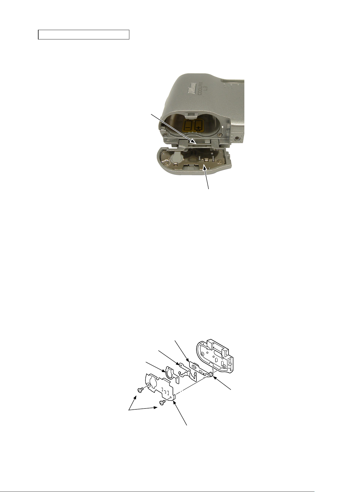
REMOVAL OF BATTERY COVER
Pull out the shaft [#211].
・
Remove the battery cover [#205].
・
VAA59004-R.3687.A
Shaft [#211]
Remove the two special screws [#108] .
・
・ Remove the terminal battery contact [#201].
・ Remove the holder [#202].
・ Remove the terminal [#203].
・ Remove the spring [#244].
Remove the knob [#204].
・
Terminal [#203]
Holder [#202]
Battery cover [#205]
Knob [#204]
Special screw [#108]
Spring [#244]
Battery contact [#201]
- D11 ・ L3 -

DISASSEMBLY OF REAR COVER
Button base [#016]
VAA59004-R.3687.A
Screw [#106]
Screw [#106]
Mode selector knob [#024]
Shaft [#021]
SD cord cover [#020]
Zoom button [#017]
Screw [#106]
Holder [#015]
Spacer [#025]
Ready window [#026]
LCD frame [#028]
Selector button [#019]
OK button [#018]
Monitor spacer [#013]
Adhesive double-coated
tape [#027]
USB cover [#023]
Spacer (For white body)
- D12 ・ L3 -
VAA59004-R.3687.A
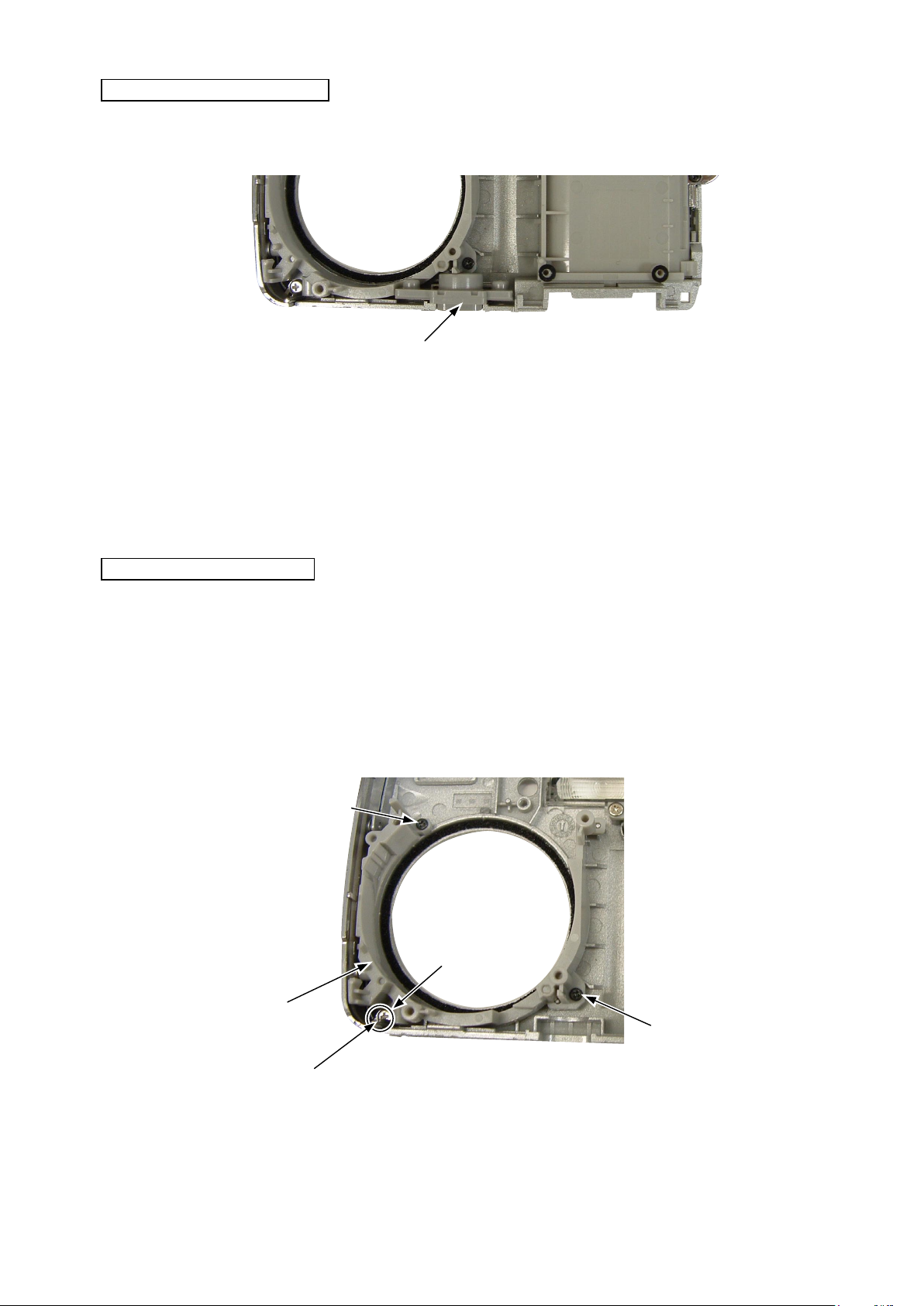
REMOVAL OF
・ Remove the tripod socket [#206].
TRIPOD SOCKET
Tripod socket [#206]
REMOVAL OF HOLDER LENS
・ Remove the two screws [#105] .
・ Remove the screw [#109].
・ Remove the lens holder [#225].
* Be careful of the protrusion of the monitor holder which is put in the clearance between the front cover and decoration
cover.
Screw [#105]
Screw [#109]
lens holder [#225]
Protrusion of the monitor holder
- D13 ・ L3 -
Screw [#105]
①
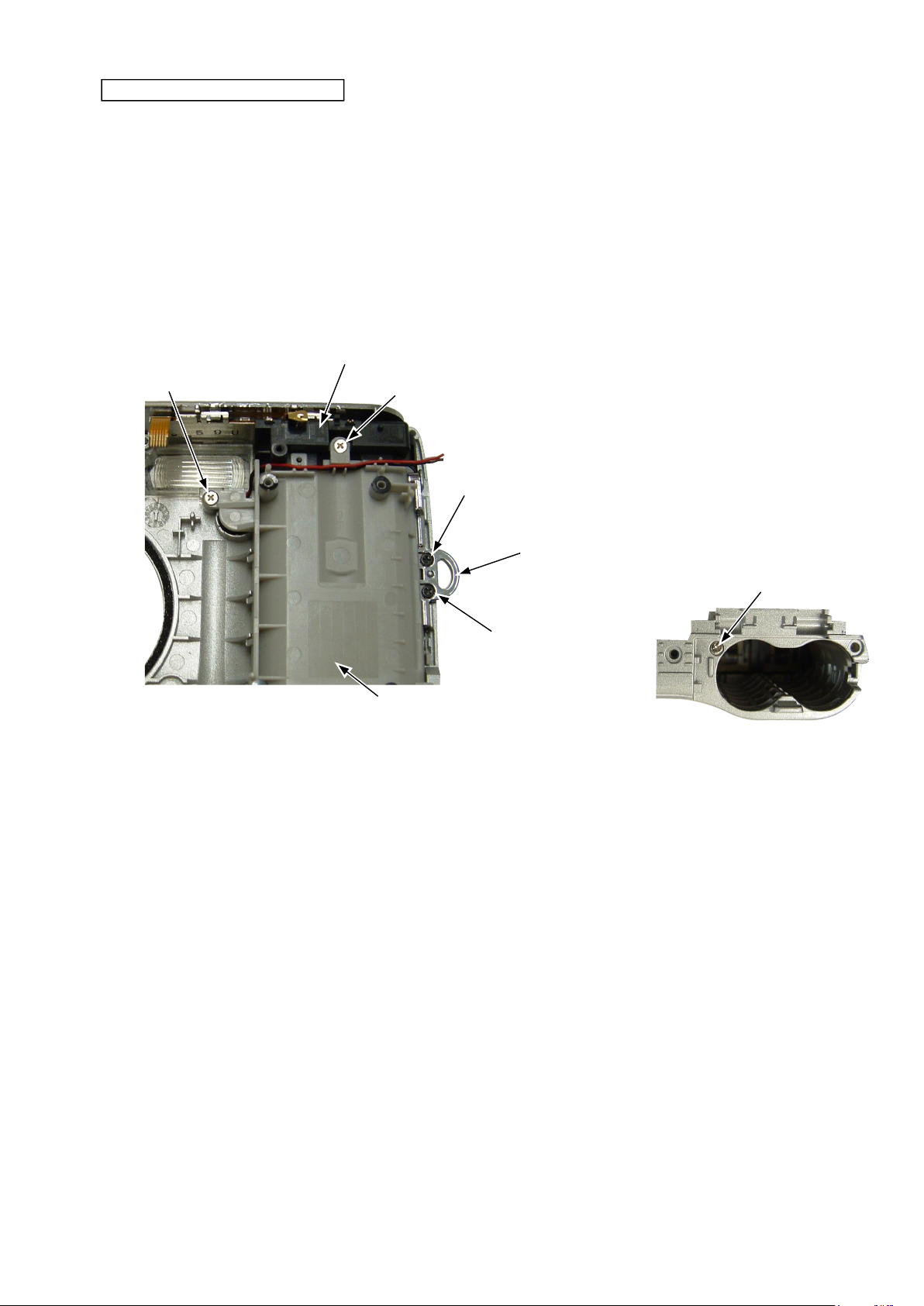
REMOVAL OF BATTERY HOLDER
・ Remove the two screws [#105].
・ Remove the strap holder [#212].
・ Remove the screw [#112].
・ Remove the screw [#109].
・ Remove the screw [#110].
・ Remove the battery holder [#217].
・ Remove the battery contact [#213] unit.
Battery contact [#213]
VAA59004-R.3687.A
Screw [#109]
Screw [#110]
Screw [#105]
Strap holder [#212]
Screw [#112]
Screw [#105]
Battery holder [#217]
- D14 ・ L3 -

REMOVAL OF MICROPHONE
・Remove the microphone [#223].
Microphone [#223]
VAA59004-R.3687.A
DISASSEMBLY OF FRONT COVER
・ Remove the SB frame [#219].
・ Take off the adhesive double-coated tape [#220].
・ Remove the DC cover [#209].
Adhesive double-coated tape [#220]
SB frame [#219]
DC cover [#209]
- D15 ・ L3 -
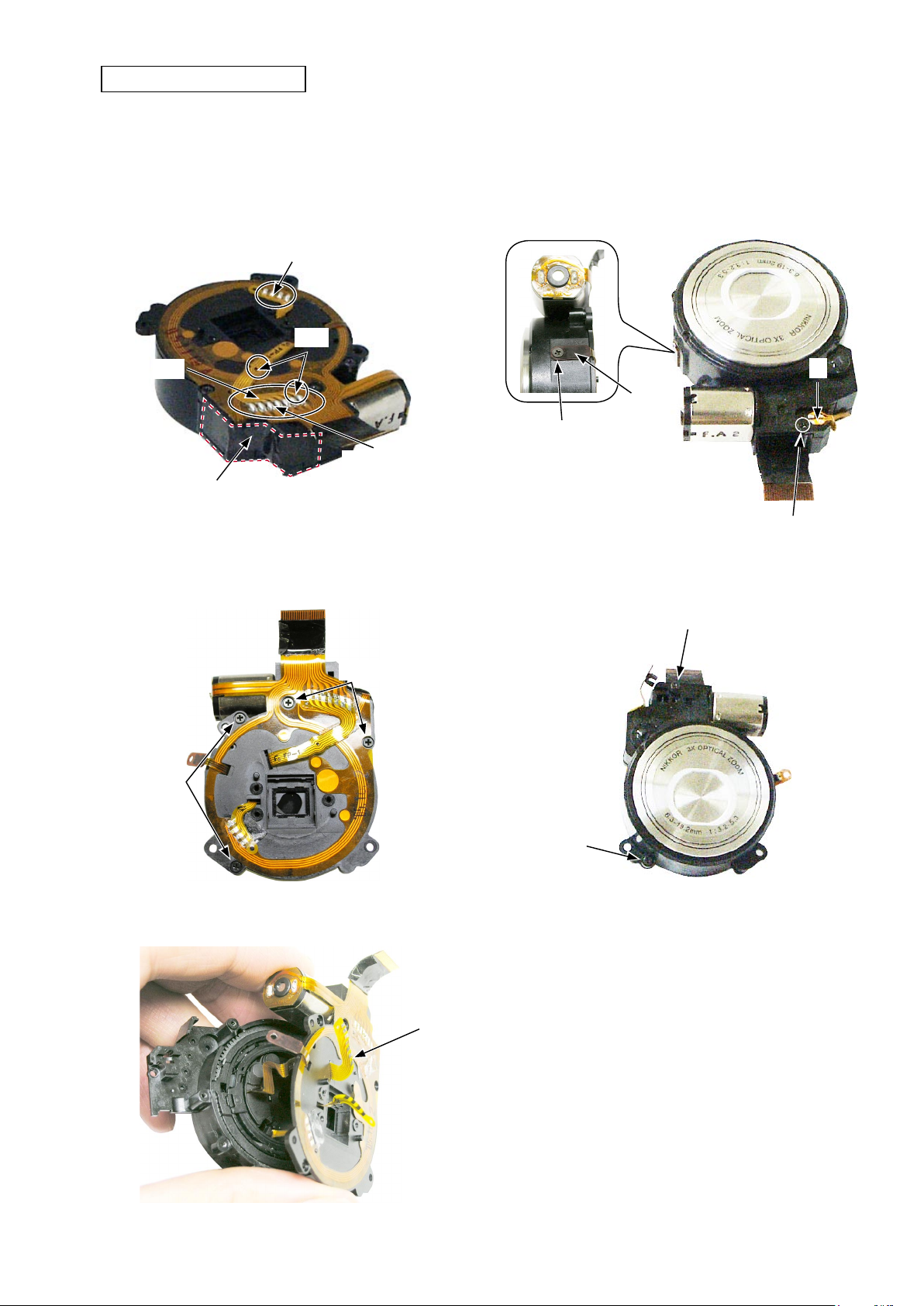
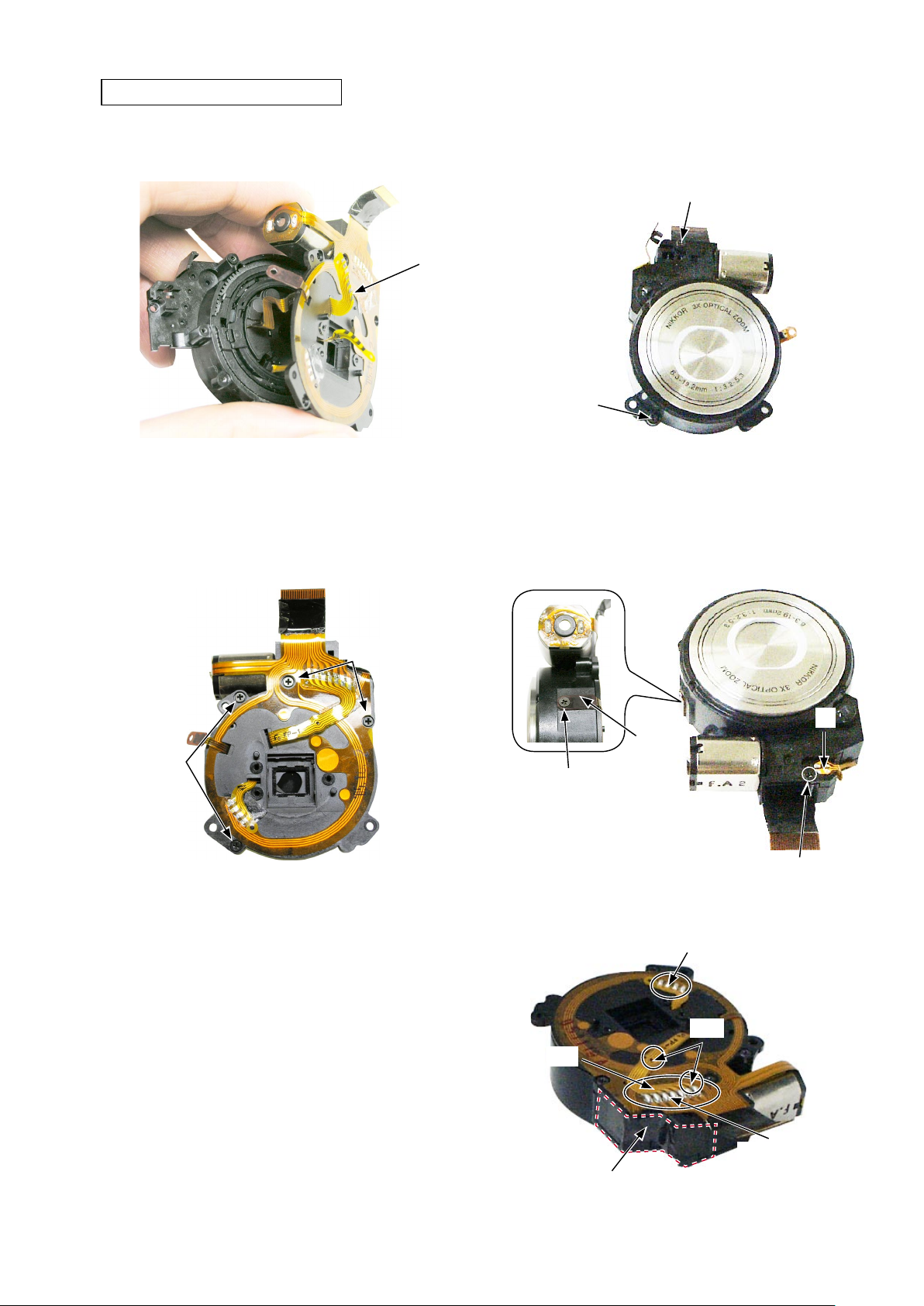
REMOVAL OF CCD MOUNT
VAA59004-R.3687.A
・ Take off the tape.
・ Remove the soldering bridges at 2 places.
Soldering bridge
Boss
FPC
Soldering bridge
Tape
・ Remove the two M1.4 × 2 screws.
・ Remove the FPC.
・ Remove the PI.
PI
FPC
Screw
M1.4 × 2
Screw
M1.4 × 2
・ Remove the four M1.4 × 3.5 screws.
Screw
Screw
M1.4 × 3.5
・ Remove the CCD mount.
M1.4 × 3.5
・ Remove the two M1.4 × 3.5screws.
Screw
M1.4 × 3.5
Screw
M1.4 × 3.5
CCD mount
- D16 ・ L3 -

VAA59004-R.3687.A
- D17 ・ L3 -
DISASSEMBLY OF CCD MOUNT GEAR UNIT
Idle Gear
Shaft C
Gear B
Worm wheel
Gear C Gear A
Remove Super X.
screw M1.4 × 1.8
Shaft A
Worm Gear
Push it out
Shaft B × 4
・ Remove the Idle gear and the shaft C. ・ Remove the gear A, gear C, gear B and Worm wheel.
・ Remove the four shafts B.
・ Remove the adhesive "Super X". ・ Remove the two M1.4 × 1.8 screws.
・ Push out the shaft A.
・ Remove the encoder and worm gear.
Encoder

REMOVAL OF FIXED BARREL
・ Remove the lens barrel unit from the fixed barrel by turning the convex section counterclockwise.
Convex section
VAA59004-R.3687.A
Turn it counterclockwise.
REMOVAL OF ROTARY BARREL UNIT
・ Remove the 1-2lens unit from the rotary barrel unit
by pushing it out from the lens side.
Lens barrel unit
・ Remove the cam barrel.
Rotary barrel unit
1-2 Lens unit
Cam barrel
Turn barrel
Push it out.
- D18 ・ L3 -
VAA59004-R.3687.A
- A1 ・ L3 -
INSTALLATION OF ROTARY BARREL UNIT
Cam barrel
Turn barrel
②
2
Turn barrel
Convex section
Groove
ASSEMBLY
・ Fit the mirror unit A of the lens barrel unit to the window B of the fi xed barrel and set the convex section C to the
groove D to install the lens barrel unit.
INSTALLATION OF FIXED BARREL
Fixed barrel
Lens barrel unit
Window B
Mirror unit A
Convex section C
Groove D
1-2 Lens unit
・ Position the mark "2" of the cam barrel and the mark
" ② " of the turn barrel as shown in the fi gure, to install
the turn barrel.
・ Fit the convex section of the 1-2 lens unit in the groove
of the turn barrel as shown in the fi gure, to install the
turn barrel.

VAA59004-R.3687.A
- A2 ・ L3 -
・ Align the encoder and convex of worm gear to mount.
・ Insert the shaft A.
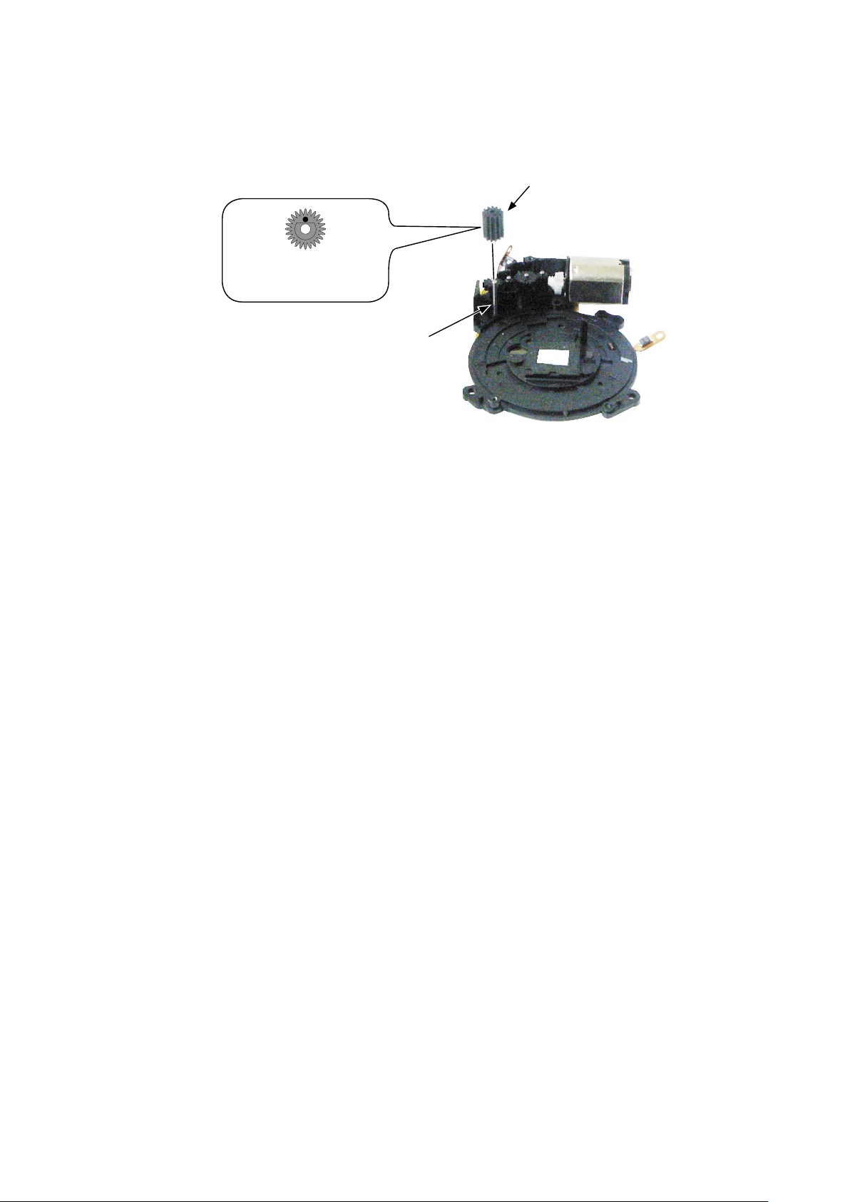
ASSEMBLY OF CCD MOUNT GEAR UNIT
・Tighten the two M1.4 × 1.8 screws.
・ Apply the adhesive "Super X".
・ Set the four shafts B.
・ Set the worm wheel , gear C, gear B, and gear A.
※ Set the gear B after setting the gear C.
Adhesive: Super X
Shaft A
Gear G
screw M1.4 × 1.8
Set condition of gear C and gear B
Gear B
Worm wheel
Gear C
Gear A
Shaft B × 4
Encoder
VAA59004-R.3687.A
- A3 ・ L3 -
・ Set the shaft C.
・ Set the idle gear.
※ The marked surface must be upwards.
Idle gear
Shaft C
This surface must be
upwards.
INSTALLATION OF CCD MOUNT
VAA59004-R.3687.A
・ Set the CCD mount.
CCD mount
・ Tighten the four M1.4 × 3.5 screws. ・ Set the PI.
・ Tighten the two M1.4 × 3.5 screws.
Screw
M1.4 × 3.5
・ Set the FPC.
・ Tighten the two M1.4 × 2 screws.
Screw M1.4 × 3.5
Screw
Screw
M1.4 × 3.5
・ Make the soldering bridges (at 2 places).
・ Adhere the tape.
M1.4 × 3.5
PI
FPC
Screw
M1.4 × 2
Screw
M1.4 × 2
Soldering bridge
Boss
FPC
- A4 ・ L3 -
Soldering bridge
Tape

Making of the lens barrel drive tool
・ Perform disassembly to D5 in the repair manual.
・ Remove the monitor holder and fix the monitor as shown in Fig. 1.
To prevent the LCD monitor from contacting with the
main PCB, process the cardboard and adhere it with the
insulation tape.
Fig.1
VAA59004-R.3687.A
・ Charging starts when the power is ON. So, be sure to cover
the solders of the SB wires and the condenser terminal with the
insulation tape.
・ Check the lens barrel operation by the W-T button.
・ Check the barrier operation by turning on/off the power.
・ Set the zoom position to the "T" side and release the shutter, then check the shutter operation.
・Set the FPC of the lens unit, which is to
be inspected, to the connector.
- A5 ・ L3 -
ASSEMBLY OF FRONT COVER
・ Set the DC cover [#209].
・ Adhere the ADHESIVE DEC FLASH [#220].
・ Set the DEC WINDOW FLASH [#219].
Adhesive double-coated tape [#220]
VAA59004-R.3687.A
SB frame [#219]
DC cover [#209]
・ Set the microphone [#223].
Microphone [#223]
- A6 ・ L3 -
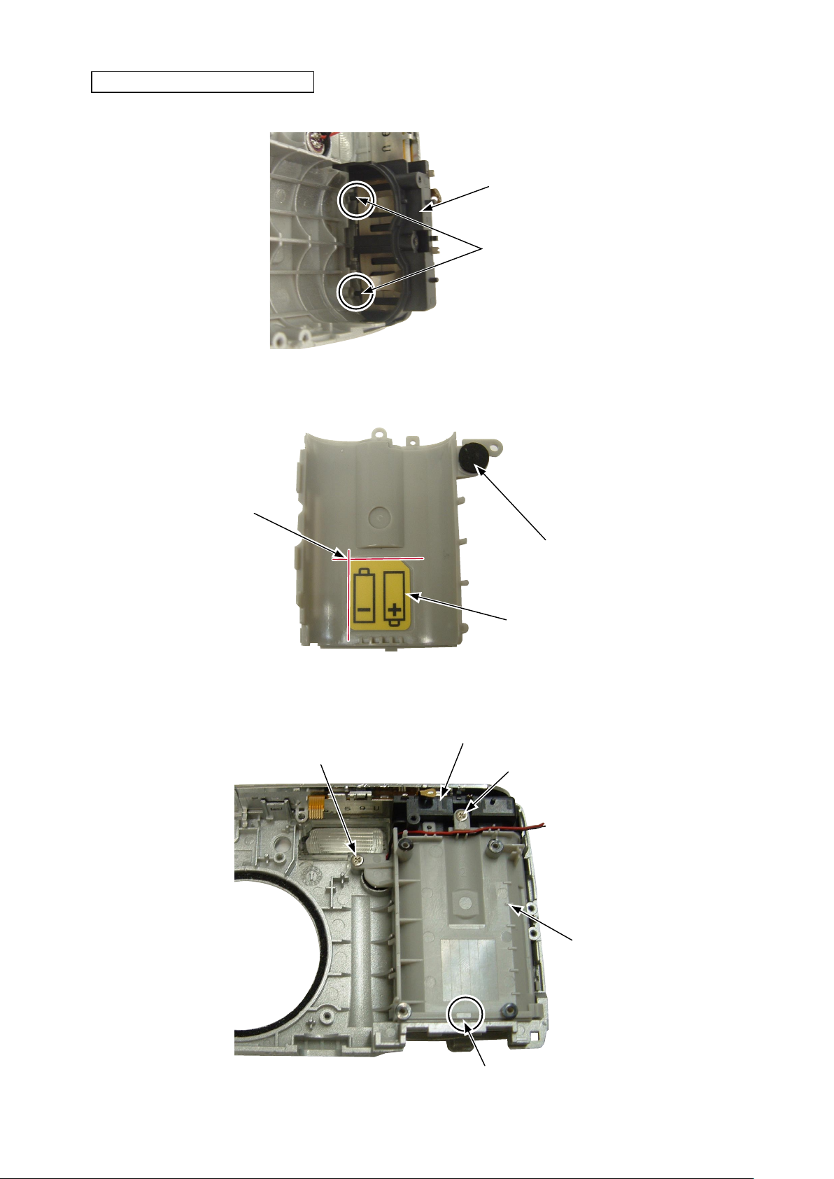
ASSEMBLY OF BATTERY HOLDER
・ Fit the bosses of the battery contact [#213] unit in the holes of the front cover [#207].
Battery contact [#213]
Boss
・ Adhere the battery label [#215] to the battery holder [#217].
・ Adhere the spacer [#216] to the battery holder [#217].
VAA59004-R.3687.A
Adhering reference position
・ Hook the battery holder [#217] to the front cover [#207].
・ Tighten the screw [#110].
・ Tighten the screw [#109].
Screw [#109]
Battery contact [#213]
Spacer [#216]
Battery
Screw [#110]
label [#215]
- A7 ・ L3 -
Battery holder [#217]
Hook
 Loading...