

Page 1

If you have any comments or suggestions on this
manual, please contact us at:
www.nihonkohden.com
Transmitter
ZM-540PA/ZM-541PA
0614-902754
Page 2

Copyright Notice
The entire contents of this manual are copyrighted by Nihon Kohden. All rights are reserved. No part
of this document may be reproduced, stored, or transmitted in any form or by any means (electronic,
mechanical, photocopied, recorded, or otherwise) without the prior written permission of Nihon
Kohden.
Page 3

GENERAL HANDLING PRECAUTIONS
This device is intended for use only by qualified medical personnel.
Use only Nihon Kohden approved products with this device. Use of non-approved
products or in a non-approved manner may affect the performance specifications
of the device. This includes, but is not limited to, batteries, recording paper, pens,
extension cables, electrode leads, input boxes and AC power.
Please read these precautions thoroughly before attempting to operate the instrument.
1. To safely and effectively use the instrument, its operation must be fully understood.
2. When installing or storing the instrument, take the following precautions:
(1) Avoid moisture or contact with water, extreme atmospheric pressure, excessive humidity and
temperatures, poorly ventilated areas, and dust, saline or sulphuric air.
(2) Place the instrument on an even, level floor. Avoid vibration and mechanical shock, even
during transport.
(3) Avoid placing in an area where chemicals are stored or where there is danger of gas leakage.
(4) The power line source to be applied to the instrument must correspond in frequency and
voltage to product specifications, and have sufficient current capacity.
(5) Choose a room where a proper grounding facility is available.
3. Before Operation
(1) Check that the instrument is in perfect operating order.
(2) Check that the instrument is grounded properly.
(3) Check that all cords are connected properly.
(4) Pay extra attention when the instrument is in combination with other instruments to avoid
misdiagnosis or other problems.
(5) All circuitry used for direct patient connection must be doubly checked.
(6) Check that battery level is acceptable and battery condition is good when using
batteryoperated models.
4. During Operation
(1) Both the instrument and the patient must receive continual, careful attention.
(2) Turn power off or remove electrodes and/or transducers when necessary to assure the
patient’s safety.
(3) Avoid direct contact between the instrument housing and the patient.
5. To Shutdown After Use
(1) Turn power off with all controls returned to their original positions.
(2) Remove the cords gently; do not use force to remove them.
(3) Clean the instrument together with all accessories for their next use.
Operator’s Manual ZM-540PA/541PA i
Page 4

6. The instrument must receive expert, professional attention for maintenance and repairs.
When the instrument is not functioning properly, it should be clearly marked to avoid
operation while it is out of order.
7. The instrument must not be altered or modified in any way.
8. Maintenance and Inspection
(1) The instrument and parts must undergo regular maintenance inspection at least every 6
months.
(2) If stored for extended periods without being used, make sure prior to operation that the
instrument is in perfect operating condition.
(3) Technical information such as parts list, descriptions, calibration instructions or other
information is available for qualified user technical personnel upon request from your Nihon
Kohden representative.
9. When the instrument is used with an electrosurgical instrument, pay careful attention to
the application and/or location of electrodes and/or transducers to avoid possible burn to
the patient.
10. When the instrument is used with a defibrillator, make sure that the instrument is
protected against defibrillator discharge. If not, remove patient cables and/or transducers
from the instrument to avoid possible damage.
ii Operator’s Manual ZM-540PA/541PA
Page 5

WARRANTY POLICY
Nihon Kohden Corporation (NKC) shall warrant its products against all defects in materials and
workmanship for one year from the date of delivery. However, consumable materials such as
recording paper, ink, stylus and battery are excluded from the warranty.
NKC or its authorized agents will repair or replace any products which prove to be defective during
the warranty period, provided these products are used as prescribed by the operating instructions
given in the operator’s and service manuals.
No other party is authorized to make any warranty or assume liability for NKC’s products.
NKC will not recognize any other warranty, either implied or in writing. In addition, service,
technical modification or any other product change performed by someone other than NKC or its
authorized agents without prior consent of NKC may be cause for voiding this warranty.
Defective products or parts must be returned to NKC or its authorized agents, along with an
explanation of the failure. Shipping costs must be pre-paid.
This warranty does not apply to products that have been modified, disassembled, reinstalled or
repaired without Nihon Kohden approval or which have been subjected to neglect or accident,
damage due to accident, fire, lightning, vandalism, water or other casualty, improper installation or
application, or on which the original identification marks have been removed.
In the USA and Canada other warranty policies may apply.
CAUTION
United States law restricts this product to sale by or on the order of a physician.
Operator’s Manual ZM-540PA/541PA iii
Page 6

Equipment Authorization Requirement
This device complies with Part 15 of the FCC (Federal Communications Commission) Rules.
Operation is subject to the following two conditions:
(1) this device may not cause harmful interference, and
(2) this device must accept any interference received, including interference that may cause
undesired operation.
This device complies with Part 95 Subpart H of the FCC Rules to be used in wireless medical
telemetry service.
Operation of this equipment requires the prior coordination with a frequency coordinator designated
by FCC for the Wireless Medical Telemetry Service.
CAUTION
To comply with the FCC radio frequency (RF) exposure compliance requirements, no
change to the antenna or the device is permitted. Any change to the antenna or the
device could result in the device, exceeding the RF exposure requirements and void
user’s authority to operate this device.
NOTE
• Use this device only indoors.
• This device has been tested and complies with FCC radiation exposure limits set forth
for an uncontrolled environment. The RF transmission power from the antenna conforms
to the general public FCC RF Exposure Guidelines in Supplement C to OET65 limit of
Specific Absorption Rate (SAR) 1.6 W/kg. The maximum SAR value measured from this
device was extremely smaller than 1.6 W/kg. This device must not be located together
with or operated in conjunction with any other unspecified antenna or transmitter.
• The devices require registration and deployment by an authorized frequency coordinator.
The ASHE (American Society for Healthcare Engineering) has been designated by the
FCC to manage the WMTS frequencies. This device has frequency bands which may
not be used in some areas. For details, contact your Nihon Kohden representative. For
details on the guidelines, refer to the ASHE home page.
iv Operator’s Manual ZM-540PA/541PA
Page 7

EMC RELATED CAUTION
This equipment and/or system complies with IEC 60601-2 International Standard for
electromagnetic compatibility for medical electrical equipment and/or system.
However, an electromagnetic environment that exceeds the limits or levels stipulated
in IEC 60601-1-2, can cause harmful interference to the equipment and/or system or
cause the equipment and/or system to fail to perform its intended function or degrade
its intended performance. Therefore, during the operation of the equipment and/or
system, if there is any undesired deviation from its intended operational performance,
you must avoid, identify and resolve the adverse electromagnetic effect before
continuing to use the equipment and/or system.
The following describes some common interference sources and remedial actions:
1. Strong electromagnetic interference from a nearby emitter source such as an
authorized radio station or cellular phone:
Install the equipment and/or system at another location. Keep the emitter source
such as cellular phone away from the equipment and/or system, or turn off the
cellular phone.
2. Radio-frequency interference from other equipment through the AC power supply of
the equipment and/or system:
Identify the cause of this interference and if possible remove this interference
source. If this is not possible, use a different power supply.
3. Effect of direct or indirect electrostatic discharge:
Make sure all users and patients in contact with the equipment and/or system are
free from direct or indirect electrostatic energy before using it. A humid room can
help lessen this problem.
4. Electromagnetic interference with any radio wave receiver such as radio or
television:
If the equipment and/or system interferes with any radio wave receiver, locate the
equipment and/or system as far as possible from the radio wave receiver.
5. Interference of lightning:
When lightning occurs near the location where the equipment and/or system is
installed, it may induce an excessive voltage in the equipment and/or system.
In such a case, disconnect the AC power cord from the equipment and/or
system and operate the equipment and/or system by battery power, or use an
uninterruptible power supply.
Operator’s Manual ZM-540PA/541PA v
Page 8

6. Use with other equipment:
When the equipment and/or system is adjacent to or stacked with other equipment,
the equipment and/or system may affect the other equipment. Before use, check
that the equipment and/or system operates normally with the other equipment.
7. Use of unspecified accessory, transducer and/or cable:
When an unspecified accessory, transducer and/or cable is connected to this
equipment and/or system, it may cause increased electromagnetic emission
or decreased electromagnetic immunity. The specified configuration of this
equipment and/or system complies with the electromagnetic requirements with the
specified configuration. Only use this equipment and/or system with the specified
configuration.
8. Use of unspecified configuration:
When the equipment and/or system is used with the unspecified system
configuration different than the configuration of EMC testing, it may cause
increased electromagnetic emission or decreased electromagnetic immunity.
Only use this equipment and/or system with the specified configuration.
9. Measurement with excessive sensitivity:
The equipment and/or system is designed to measure bioelectrical signals with
a specified sensitivity. If the equipment and/or system is used with excessive
sensitivity, artifact may appear by electromagnetic interference and this may
cause mis-diagnosis. When unexpected artifact appears, inspect the surrounding
electromagnetic conditions and remove this artifact source.
If the above suggested remedial actions do not solve the problem, consult your Nihon
Kohden representative for additional suggestions.
vi Operator’s Manual ZM-540PA/541PA
Page 9

Conventions Used in this Manual and Instrument
Warnings, Cautions and Notes
Warnings, cautions and notes are used in this manual to alert or signal the reader to specific
information.
WARNING
A warning alerts the user to the possible injury or death associated with the use or
misuse of the instrument.
CAUTION
A caution alerts the user to possible injury or problems with the instrument associated
with its use or misuse such as instrument malfunction, instrument failure, damage to
the instrument, or damage to other property.
NOTE
A note provides specific information, in the form of recommendations, prerequirements,
alternative methods or supplemental information.
Operator’s Manual ZM-540PA/541PA vii
Page 10
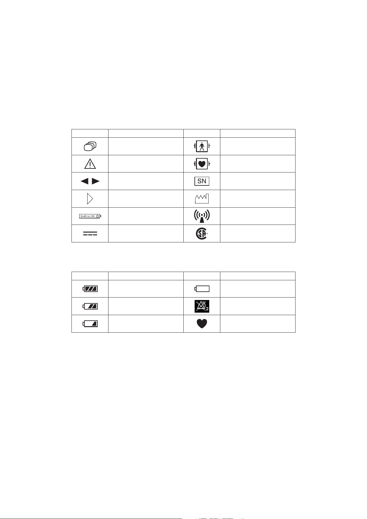
Explanations of the Symbols in this Manual and Instrument
The following symbols found in this manual/instrument bear the respective descriptions as given.
On Panel
Symbol Description Symbol Description
Change screen
Attention, consult operator’s
manual
Defibrillation proof type BF
applied part
Defibrillation proof type CF
applied part
Moves cursor, scrolls data Serial number
Direction for attaching battery
cover
Direction for inserting battery
Year of manufacture
RF transmitter
Non-ionizing radiation
Direct current CSA mark
On LCD
Symbol Description Symbol Description
Full battery
Battery very weak
Replace battery
Battery 2/3 full Alarm suspended
Low battery
NIBP cannot be measured
QRS/pulse sync mark
viii Operator’s Manual ZM-540PA/541PA
Page 11

Intended Use
General
The ZM-540PA and ZM-541PA transmitter transmits ECG, respiration and pulse waveforms, SpO2
and NIBP data from a patient to a Nihon Kohden monitor for continuous monitoring. The front LCD
displays ECG (or pulse wave), numeric values of monitoring parameters, NIBP measuring mode and
interval, messages and battery condition.* It also displays the compressed waveform and numeric
data of the latest 10 minutes.
* Essential performance of this transmitter.
The difference between the ZM-540PA and ZM-541PA is the transmission frequency range.
ZM-540PA: 608.0250 MHz (channel number 9002) to 613.9750 MHz (channel number 9478)
ZM-541PA: 1395.0250 MHz (channel number E002) to 1399.9750 MHz (channel number E398)
1427.0250 MHz (channel number E502) to 1431.9750 MHz (channel number E898)
The transmitter channel can be changed with a QI-901PK channel writer.
Read the operator’s manual for the receiving monitor together with this manual before use.
WARNING
Do not use the same transmitter on more than one patient at the same time. Do not
connect different sensors on different patients to the same transmitter.
CAUTION
• Do not use the same channel for different patients. If the same channel is used
for two patients, the two patients’ data will be lost due to mutual modulation
interference, or another patient’s data may appear on the receiving monitor screen.
• Do not use two transmitters with adjacent channels in the same hospital. If
transmitters with adjacent channels are used, their radio waves interfere with each
other.
CAUTION
Be aware that signal loss and artifact may occur because of the multipath
cancellation* when using a transmitter.
* Multipath Cancellation (Standing Wave Interference)
When a radio wave reflects off a surface, there may be some points in the room where the
Operator’s Manual ZM-540PA/541PA 1
Page 12

reflected and direct waves are exactly out of phase. At these points in the room, the reflected
and direct waves cancel each other out so that the signal strength is 0. This is called “multipath
cancellation” or “standing wave interference”. Locations where signal loss occurs are called “null
spots”. If the transmitter is moving or nearby people or objects are moving, null spots can occur
anytime and anywhere.
NOTE
• To prevent interference between channels, assign a channel administrator in the hospital
and only he or she should manage channel assignment.
• Use Nihon Kohden parts and accessories to assure maximum performance from your
instrument.
• For stable signal reception, it is recommended to use a diversity antenna system on the
receiving monitor. Otherwise, spike noise from transient fading of electric field strength
(for example, people moving) may interfere with the transmitter signal and may be
mistaken as an arrhythmia on the receiving monitor.
• For details on antennas and antenna construction, contact your Nihon Kohden
representative. You can also refer to the Telemetry System Installation Guide.
• Do not diagnose a patient based on only part of the monitoring data on the transmitter or
only on the data acquired by the transmitter. Overall judgment must be performed by a
physician who understands the features, limitations and characteristics of the transmitter
by reading this operator’s manual thoroughly and by reading the biomedical signals
acquired by other instruments.
Receiving Monitor
Any Nihon Kohden receiving monitor (central monitor with multiple patient receiver) can receive
signals from this transmitter as long as the protocol version and channel setting are the same on the
receiving monitor and transmitter.
NOTE
• For details on the receiving monitor and upgrade information, contact your Nihon Kohden
representative.
• The transmitter does not give any patient alarm, only a “no battery” alarm. Patient alarms
must be managed on the receiving monitor.
2 Operator’s Manual ZM-540PA/541PA
Page 13
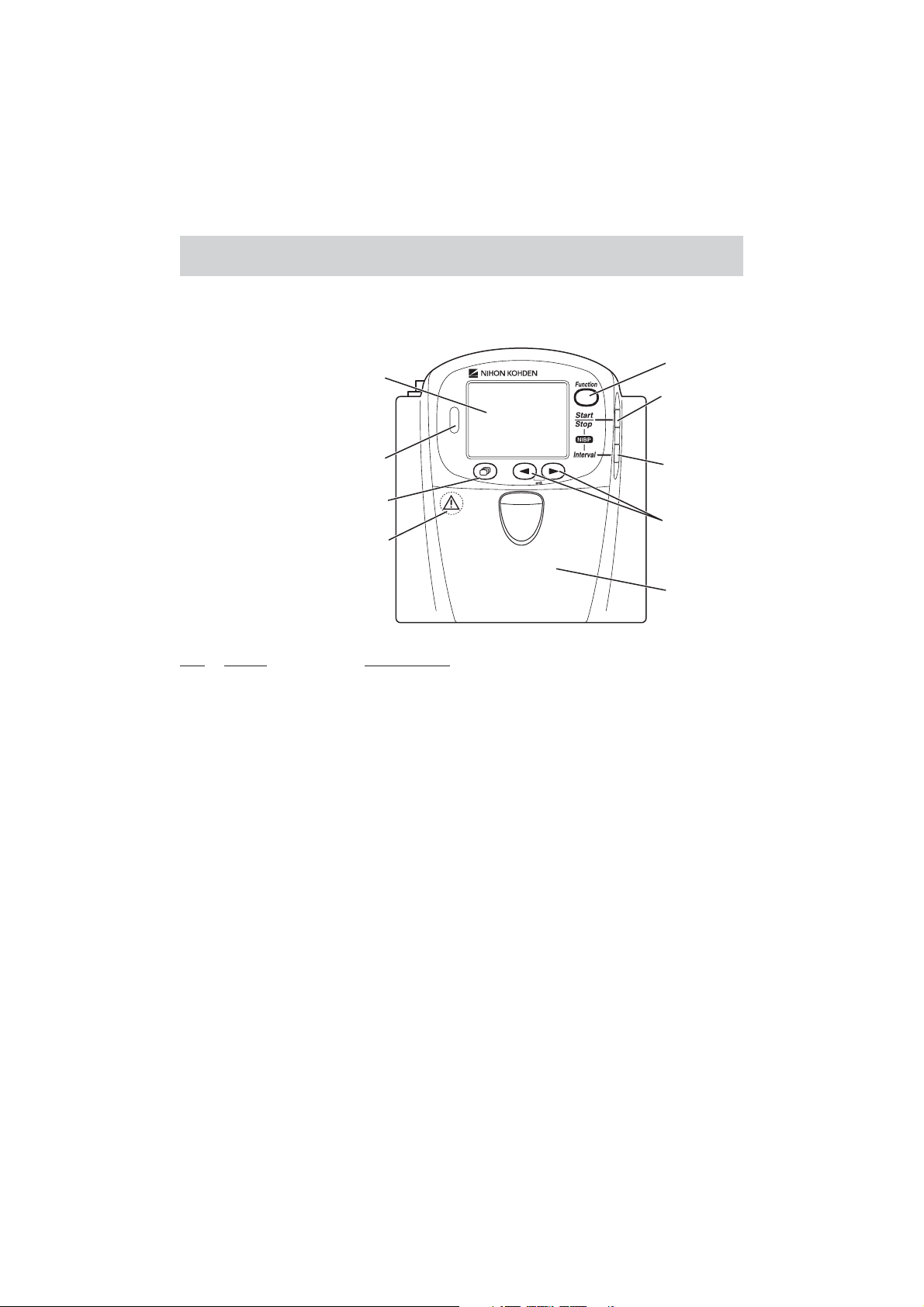
Panel Description
Front Panel
1
4
5
2
6
3
7
Refer to the WARNING
on the next page.
8
No. Name Description
1 LCD Displays numeric values, ECG or pulse wave, NIBP measuring
mode and interval, messages and battery status. For details, refer to
the “Screen Descriptions” section.
2 Infrared receiver Used for upgrading the transmitter software.
3 Screen key Toggles the screen in the following order.
After power on: Start up → Check electrodes → Numeric and
waveform → Waveform review → Numeric review → Display off
→ Check electrodes …
After auto display off: Numeric and waveform → Waveform
review → Numeric review → Display off → Check electrodes →
Numeric and waveform …
On a SETUP or CHECK screen, this key cancels changing setting
or exits the screen.
Operator’s Manual ZM-540PA/541PA 3
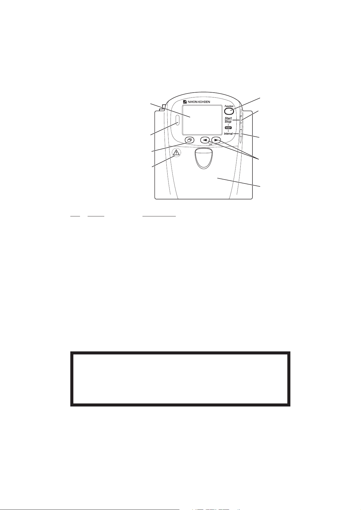
Page 14
1
4
5
2
6
3
7
Refer to the WARNING
below.
8
No. Name Description
4 Function key Depending on the setting on the transmitter, this key suspends
alarms, pauses monitoring on the receiving monitor or transmits
“Patient confirmed” message.
On a SETUP screen, this key registers the selected setting and
moves the cursor to the next setting item.
On a CHECK screen, this key starts or stops maintenance test.
5 NIBP Start/Stop key Starts/stops NIBP measurement in selected mode.
6 NIBP Interval key Selects NIBP measurement mode.
7 Lead/Scroll keys On the numeric and waveform screen, these keys change the ECG
lead.
On the waveform review screen, these keys scroll data.
On a SETUP screen, these keys move the cursor.
8 Battery case Contains three 1.5 V dry cell batteries (AA TYPE).
WARNING
Close the battery case cover during operation. If the transmitter is used with the
battery case cover open, anyone who touches the opened battery case may receive
an electrical shock when defibrillation is performed. Touching the opened battery case
may cause electrostatic discharge and intermittently interfere with the waveform or
data.
4 Operator’s Manual ZM-540PA/541PA
Page 15
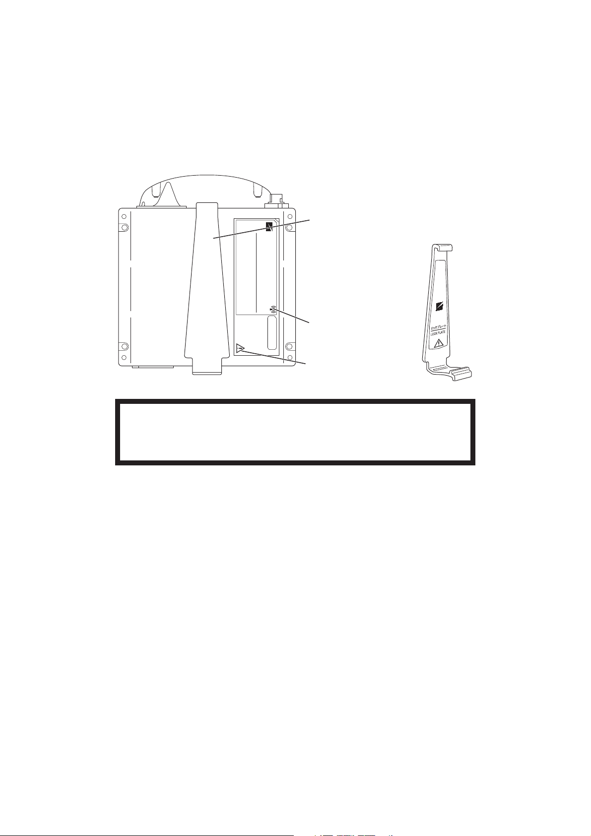
Rear Panel
Lock plate
Fastens the transmitter to an NIBP cuff.
Refer to the symbol
page.
Refer to the WARNING
below.
WARNING
This transmitter is not waterproof. If detergent or liquid spills into the transmitter, stop
using it and contact your Nihon Kohden representative. If a wet transmitter is used,
the patient or operator may receive an electrical shock or injury.
Operator’s Manual ZM-540PA/541PA 5
Page 16
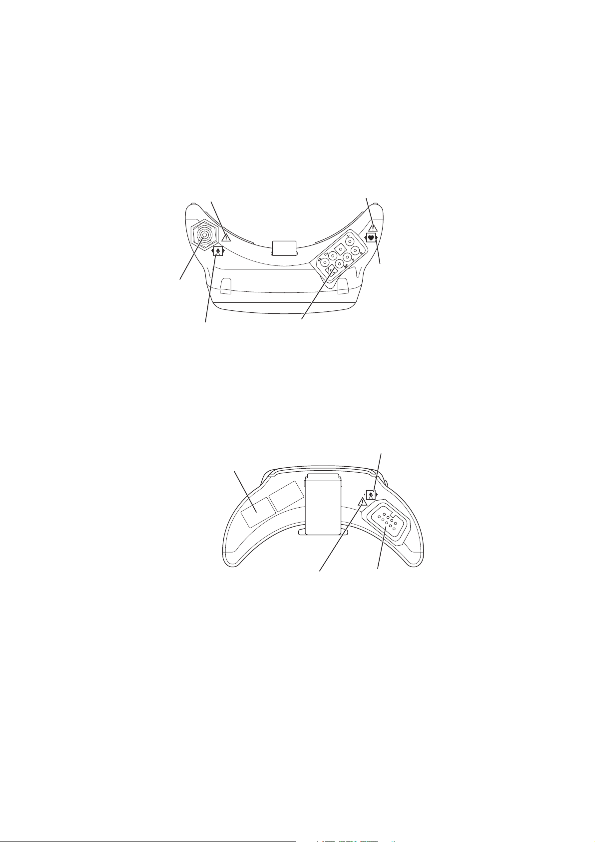
Top Panel
Refer to the WARNING on the
next page.
NIBP socket:
Connects the cuff
hose.
Refer to the symbol page.
Bottom Panel
Channel number label:
Indicates the channel number of the
transmitter. Attach the channel number label
to the panel of the receiving monitor.
Refer to the WARNING on the
next page.
Refer to the symbol
page.
ECG/impedance RESP socket:
Connects the electrode lead for measuring
ECG and/or respiration (impedance).
Refer to the symbol page.
Refer to the WARNING
on the next page.
6 Operator’s Manual ZM-540PA/541PA
SpO2 socket:
Connects the SpO2
probe.
Page 17

WARNING
Before defibrillation, all persons must
keep clear of the bed and must not
touch the patient or any equipment or
cord connected to the patient. Failure
to follow this warning may cause
electrical shock or injury.
WARNING
When performing defibrillation,
discharge as far as possible from
electrodes, patches and any gel,
cream or medicine on the chest of the
patient. If there is a possibility that the
defibrillator paddle could touch these
materials, remove them from the
patient. If the defibrillator paddle
directly contacts these materials, the
discharged energy may cause skin
burn to the patient.
WARNING
When the transmitter is used with an
electrosurgical unit (ESU), firmly
attach the entire area of the ESU
return plate. Otherwise, the current
from the ESU flows into the electrodes
of the transmitter, causing electrical
burn where the electrodes are
attached. For details, refer to the ESU
manual.
CAUTION
Do not shake or swing the transmitter
while holding the leads or cables
connected to the transmitter. The
transmitter may come off and injure
someone or damage surrounding
instruments.
Operator’s Manual ZM-540PA/541PA 7
Page 18

Important Safety Information
General
WARNING
Never use the transmitter in the
presence of any flammable anesthetic
gas or high concentration oxygen
atmosphere. Failure to follow this
warning may cause explosion or fire.
WARNING
Do not take this transmitter into the
MRI test room. This transmitter is not
designed to be used during MRI tests.
WARNING
Before defibrillation, all persons must
keep clear of the bed and must not
touch the patient or any equipment or
cord connected to the patient. Failure
to follow this warning may cause
electrical shock or injury.
WARNING
Never use the transmitter in a
hyperbaric oxygen chamber. Failure to
follow this warning may cause
explosion or fire.
WARNING
When performing MRI test, remove all
electrodes, probe and cuff from the
patient which are used with this
transmitter. Failure to follow this
warning may cause skin burn on the
patient. For details, refer to the MRI
manual.
WARNING
When performing defibrillation,
discharge as far as possible from
electrodes, patches and any gel,
cream or medicine on the chest of the
patient. If there is a possibility that the
defibrillator paddle could touch these
materials, remove them from the
patient. If the defibrillator paddle
directly contacts these materials, the
discharged energy may cause skin
burn to the patient.
8 Operator’s Manual ZM-540PA/541PA
Page 19

WARNING
When the transmitter is used with an
electrosurgical unit (ESU), firmly
attach the entire area of the ESU
return plate. Otherwise, the current
from the ESU flows into the electrodes
of the transmitter, causing electrical
burn where the electrodes are
attached. For details, refer to the ESU
manual.
WARNING
This transmitter is not waterproof. If
detergent or liquid spills into the
transmitter, stop using it and contact
your Nihon Kohden representative. If a
wet transmitter is used, the patient or
operator may receive an electrical
shock or injury.
WARNING
Close the battery case cover during
operation. If the transmitter is used
with the battery case cover open,
anyone who touches the opened
battery case may receive an electrical
shock when defibrillation is performed.
Touching the opened battery case
may cause electrostatic discharge and
intermittently interfere with the
waveform or data.
CAUTION
Only use Nihon Kohden specified
electrodes, electrode leads, SpO
probes, and NIBP cuffs. Otherwise,
the maximum performance from the
transmitter cannot be guaranteed.
2
CAUTION
The measurement values and
displayed waveforms on the
transmitter and receiving monitor may
be different due to timing delay of the
display or difference in detection
settings.
WARNING
Do not use the same transmitter on
more than one patient at the same
time. Do not connect different sensors
on different patients to the same
transmitter.
CAUTION
Do not reuse disposable parts and
accessories.
CAUTION
Do not shake or swing the transmitter
while holding the leads or cables
connected to the transmitter. The
transmitter may come off and injure
someone or damage surrounding
instruments.
Operator’s Manual ZM-540PA/541PA 9
Page 20

CAUTION
Be aware that signal loss and artifact
may occur because of the multipath
cancellation* when using a transmitter.
* Multipath Cancellation (Standing Wave
Interference)
When a radio wave reflects off a surface,
there may be some points in the room where
the reflected and direct waves are exactly
out of phase. At these points in the room, the
reflected and direct waves cancel each other
out so that the signal strength is 0. This is
called “multipath cancellation” or “standing
wave interference”. Locations where signal
loss occurs are called “null spots”. If the
transmitter is moving or nearby people or
objects are moving, null spots can occur
anytime and anywhere.
CAUTION
Turn off the power of mobile phones,
small wireless devices and other
devices which produce strong
electromagnetic interference around a
patient (except for devices allowed by
the hospital administrator). Radio
waves from devices such as mobile
phones or small wireless devices may
be mistaken as pulse waves and the
displayed data may be incorrect.
CAUTION
• Do not use the same channel
for different patients. If the same
channel is used for two patients, the
two patients’ data will be lost due to
mutual modulation interference, or
another patient’s data may appear
on the receiving monitor screen.
• Do not use two transmitters with
adjacent channels in the same
hospital. If transmitters with
adjacent channels are used, their
radio waves interfere with each
other.
Output Signal
WARNING
Do not use the output signal from the receiving monitor as the synchronization signal
for other equipment such as IABP, MRI, echocardiography or defibrillator. There may
be time delay between the monitor and the other equipment caused by waveform
transmission delay and spike noise may interfere on the output signal and be
mistaken as a trigger.
10 Operator’s Manual ZM-540PA/541PA
Page 21

Battery
CAUTION
Battery replacement must be
performed by the operator. When
replacing the batteries of a transmitter
that is currently used for a patient,
disconnect the electrode leads from
the transmitter before replacing
batteries or do not touch the patient
during replacement.
Refer to the battery and battery
charger manuals for details on
handling the batteries.
CAUTION
Transmitter Channel Management
WARNING
The following actions must be taken to properly receive the transmitter signal of the
correct patient on the receiving instrument. Otherwise, there may be signal loss or
signals may mix causing a serious accident, such as monitoring a different patient.
• Assign a channel administrator in the hospital and only he or she should manage
channel assignment.
• The channel administrator must manage the channels in the facility so that there is
no signal interference.
• When the transmitter channel is changed, the channel administrator must check
that the channel on the receiving monitor is also changed and the signal is properly
received.
• The channel administrator must replace the channel number label on the
transmitter with the new one after changing the channel.
Operator’s Manual ZM-540PA/541PA 11
Page 22

For Patients Using Implantable Pacemaker
WARNING
Interaction Between Minute Ventilation Rate-Adaptive Pacemakers and Cardiac
Monitoring and Diagnostic Equipment*
The bioelectric impedance measurement sensor of a minute ventilation rate-adaptive
implantable pacemaker may be affected by transmitter which is connected to the
same patient. If this occurs, the pacemaker may pace at its maximum rate and the
transmitter may give incorrect data to the monitor. If this occurs, disconnect the
electrode leads from the patient or change the setting on the pacemaker by referring
to the pacemaker’s manual. For more details, contact your pacemaker representative
or Nihon Kohden representative.
* Minute ventilation is sensed in rate-adaptive pacemakers by a technology known as bioelectric
impedance measurement (BIM). Many medical devices in addition to pacemakers use this
technology. When one of these devices is used on a patient with an active, minute ventilation rateadaptive pacemaker, the pacemaker may erroneously interpret the mixture of BIM signals created
in the patient, resulting in an elevated pacing rate.
For more information, see the FDA web site.
http://www.fda.gov/cdrh/safety.html
ECG Monitoring
CAUTION
Only use Nihon Kohden specified
electrodes and electrode leads. When
other electrodes or electrode leads
are used, the “CHECK
ELECTRODES” message may appear
and monitoring may stop.
12 Operator’s Manual ZM-540PA/541PA
When the “ELECTRODE OFF” or
“CHECK ELECTRODES” message is
displayed on the receiving monitor,
ECG is not monitored properly and
the ECG alarm does not function.
Check the electrode, electrode leads,
and if necessary, replace with new
ones.
CAUTION
Page 23

SpO2 Monitoring
WARNING
SpO2 measurement may be incorrect
in the following cases.
• When the patient’s
carboxyhemoglobin or
methemoglobin increases
abnormally.
• When dye is injected in the blood.
• When using an electrosurgical unit.
• During CPR.
• When measuring at a site with
venous pulse.
• When there is body movement.
• When the pulse wave is small
(insufficient peripheral circulation).
WARNING
• When using the TL-201T finger
probe, do not fasten the probe and
cable to the finger by wrapping
with tape. This may cause burn,
congestion or pressure necrosis
from poor blood circulation.
• When using probes other than the
TL-201T finger probe, to avoid poor
circulation, do not wrap the tape too
tight. Check the blood circulation
condition by observing the skin
color and congestion at the skin
peripheral to the probe attachment
site. Even for short-term monitoring,
there may be burn or pressure
necrosis from poor blood circulation,
especially on neonates or low
birth weight infants whose skin is
delicate. Accurate measurement
cannot be performed on a site with
poor peripheral circulation.
WARNING
When not monitoring SpO2,
disconnect the SpO
transmitter. Otherwise, noise from the
probe sensor may interfere and
incorrect data is displayed on the
screen.
cable from the
2
WARNING
Check the circulation condition by
observing the skin color at the
measurement site and pulse
waveform. Change the measurement
site every 8 hours for disposable
probes and every 4 hours for reusable
probes (every 8 hours for TL-630T/TL631T series probe). The skin
temperature may increase at the
attached site by 2 or 3°C (4 or 5°F)
and cause a burn or pressure
necrosis. When using the probe on the
following patients, take extreme care
and change the measurement site
more frequently according to
symptoms and degree.
• Patient with a fever
• Patient with peripheral circulation
insufficiency
• Neonate or low birth weight infant
with delicate skin
Operator’s Manual ZM-540PA/541PA 13
Page 24

WARNING
When monitoring SpO2 of a patient
who is receiving photodynamic
therapy, the light from the finger probe
sensor may cause a burn.
Photodynamic therapy uses a
photosensitizing agent that has a side
effect of photosensitivity.
CAUTION
Refer to the probe instruction manual
for details.
CAUTION
NIBP and SpO2 can be measured on
the same limb, but the SpO
monitoring might not be accurate
during NIBP measurement. Be careful
when reading the SpO
* Monitoring SpO2 during NIBP Measurement
When the SpO
probe is attached to the
2
same limb as the NIBP cuff, the blood
flow decreases during NIBP measurement
and pulse wave cannot be detected and
SpO
cannot be monitored properly. When
2
“INHIBIT SpO
DURING NIBP” on the
2
PARAMETER SETUP screen is set to ON
(factory default setting), SpO
paused during NIBP measurement to avoid
SpO
alarm occurrence. However, when
2
monitoring SpO
on the same limb as the
2
NIBP, be careful when reading SpO
2
values.*
2
monitoring is
2
values.
2
CAUTION
The disposable probe is not sterilized.
Use the disposable probe only for a
single patient. Never reuse the
disposable probe for another patient
because it causes cross infection.
CAUTION
While a patient is on medication which
causes vasodilation, the pulse
waveform may change and in rare
cases the SpO
value might not be
2
displayed.
CAUTION
Normal external light does not affect
monitoring but strong light such as a
surgical light or sunlight may affect
monitoring. If affected, cover the
measuring site with a blanket.
CAUTION
When a message indicates a faulty
probe, stop monitoring and replace
the probe with a new one.
14 Operator’s Manual ZM-540PA/541PA
Page 25

CAUTION
Do not use a damaged or
disassembled probe. It causes
incorrect measurement and may
injure the patient.
CAUTION
Do not use a probe which is
deteriorated by aging. Accurate
measurement cannot be performed.
CAUTION
If the attachment site is dirty with
blood or bodily fluids, clean the
attachment site before attaching the
probe. If there is nail polish on the
attachment site, remove the polish.
Otherwise, the amount of transmitted
light decreases, and measured value
may be incorrect or measurement
cannot be performed.
CAUTION
Do not pull or bend the probe cable,
and do not put caster feet on the
probe cable. Do not immerse the
disposable probe cable in chemical
solutions or water. Failure to follow
these instructions may cause cable
discontinuity, short circuit, skin burn
on the patient and incorrect
measurement data. Replace any
broken probe with a new one.
CAUTION
If the skin gets irritated or redness
appears on the skin from the probe,
change the attachment site or stop
using the probe. Take extreme care for
the patients with delicate skin.
CAUTION
When the probe is attached on an
appropriate site with sufficient
circulation and the error message
confirming the probe attachment
repeatedly appears, the probe may be
deteriorated. Replace it with a new
one.
Operator’s Manual ZM-540PA/541PA 15
Page 26

NIBP Monitoring
WARNING
Be careful when measuring NIBP on a
patient with known bleeding disorders
or coagulation. After NIBP
measurement, there may be dot
hemorrhage, or circulatory disorder by
thrombus where the cuff is attached.
WARNING
When performing NIBP
measurements in STAT mode or 5
minute intervals, periodically remove
the cuff from the patient for ventilation.
The skin temperature may increase at
the cuff attachment site by 2 or 3°C (4
or 5°F). When measuring a patient
with a fever or peripheral circulation
insufficiency, it may cause a burn.
CAUTION
Do not wrap the cuff on an arm or
thigh which is used for injection. NIBP
measurement on an arm or thigh
which is used for injection may cause
reflux of blood and stop injection.
WARNING
NIBP measurement may be incorrect
in the following cases.
• When using an electrosurgical unit
• When there is body movement
• When the pulse wave is small
(insufficient peripheral circulation)
• Too many arrhythmias
• When there is vibration
• When there is a rapid blood
pressure change
• During CPR
CAUTION
Do not wrap the cuff too tight. It may
cause poor blood circulation and
congestion. If the cuff is wrapped too
loosely, the NIBP value may increase.
CAUTION
Do not attach the cuff to the site
where there is injury or inflammation.
If the skin gets irritated or redness
appears on the skin from the cuff,
change the attachment site or stop
using the cuff. Take extreme care on
the patients with delicate skin.
16 Operator’s Manual ZM-540PA/541PA
When using an extension hose, check
that the extension hose is not bent or
squeezed. Otherwise, the cuff might
not inflate or deflate. If the cuff cannot
deflate, it may cause congestion on
the patient at the cuff attachment site.
CAUTION
Page 27

CAUTION
When performing NIBP measurement
repeatedly, have a rest between
measurements to recover adequate
circulation.
Maintenance
CAUTION
This transmitter is not waterproof. If
detergent or liquid spills into the
transmitter, stop cleaning or
disinfecting it and contact your Nihon
Kohden representative. The
transmitter needs to be checked for
safety and function before use.
CAUTION
Never disassemble or repair the
transmitter. Disassembly and repair
must be performed by qualified
service personnel.
Operator’s Manual ZM-540PA/541PA 17
Page 28

Preparation on Transmitter
Batteries
WARNING and CAUTION for Handling Batteries
CAUTION
Refer to the battery and battery
charger manuals for details on
handling the batteries.
CAUTION
Do not handle the batteries with wet
hands.
When the transmitter is not in use,
remove the batteries. When the
batteries are installed, battery power
is consumed even when
measurement is not performed. When
NiMH batteries are left in the
transmitter when it is not used, the
batteries may overdischarge and leak
liquid which makes the batteries
unusable and damages the
transmitter.
CAUTION
NOTE
Remove the batteries from the transmitter before disposing of it.
Battery Lifetime
Use three AA type alkaline dry cell batteries. NiMH batteries can also be used but the lifetime of
alkaline batteries is longer. The lifetime of NiMH batteries is about 1/2 of alkaline batteries (when
fully charged).
With new Nihon Kohden recommended alkaline batteries, the transmitter can continuously measure
ECG, respiration, SpO
temperature, NIBP is measured in auto mode at 60 minute intervals and SpO
index finger of a male patient with weight 60 kg. Operation time depends on the thickness of the
SpO
probe attachment site.
2
and NIBP for approximately 1 day. The measurement is performed at room
2
is measured on an
2
Recommended batteries
NiMH secondary: SANYO HR-3UF (W)
Battery charger: SANYO NC-M55
Alkaline primary: Nihon Kohden Medipower (equivalent to Panasonic LR6 (G))
18 Operator’s Manual ZM-540PA/541PA
Page 29
Installing (Replacing) Batteries
CAUTION
Battery replacement must be performed by the operator. When replacing the batteries
of a transmitter that is currently used for a patient, disconnect the electrode leads
from the transmitter before replacing batteries or do not touch the patient during
replacement.
If electrode leads are attached to the patient and the person replacing batteries touches the patient
during battery replacement, excess patient leakage current may flow into the patient.
NOTE
• Replace all batteries at the same time.
• Do not use different types of batteries together.
• Insert the batteries with the correct polarity (+ and –).
• The capacity of rechargeable NiMH batteries is reduced if the batteries are recharged
before they are fully discharged. For details, refer to the battery operator’s manual.
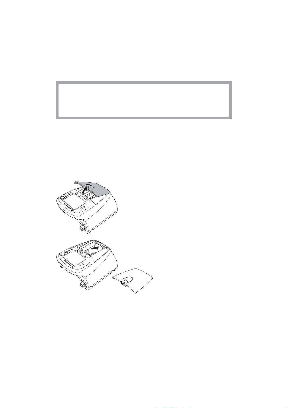
1. Remove the battery case cover.
2. Insert three new or fully charged batteries into
the battery case observing the correct polarity.
Operator’s Manual ZM-540PA/541PA 19
Page 30
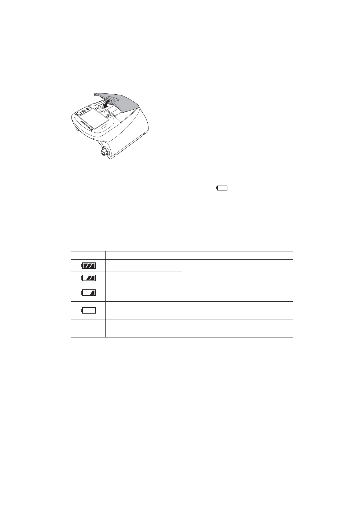
3. Close the cover.
The transmitter is automatically turned on when the
batteries are installed and the cover is closed.
Situations Requiring Battery Replacement
Replace the batteries when any of the following occurs:
• The transmitter displays the “BATTERY WEAK” message or “
• The transmitter generates a constant alarm (continuous “peep” sound).
• The transmitter LCD does not display anything when the power is turned on.
• The receiving monitor displays a battery replacement message.
Battery Level Indication
The following icons on the LCD indicate the battery level. When “PROTOCOL” on the SYSTEM
SETUP screen is set to 57, the battery level indication is transmitted to the receiving monitor.
Indication Battery Level Message on the Receiving Monitor
Fully charged batteries
” icon.
No indication
Batteries are 2/3 full.
Batteries are low. NIBP cannot
be measured. Replace batteries.
Batteries are very weak.
Dead batteries
There is no message on the monitor.
Message requiring battery replacement is
displayed.
No signal can be transmitted to the monitor.
There is no indication on the monitor.
Turning On the Transmitter
When the batteries are installed correctly, the power is turned on. A one second “peep” sounds and
the startup screen appears, then the check electrodes screen appears. (There is no “peep” sound
when there is no battery power.)
20 Operator’s Manual ZM-540PA/541PA
Page 31

After checking that the ECG is stable on the check electrodes screen, press the Screen key to display
the numeric and waveform screen.
For details on the screen, refer to the “Screen Descriptions” section.
Check Items Before Use
Before turning on the transmitter power, check the following to confirm that the transmitter can be
used in normal and safe condition.
Appearance
• There are no damaged or dirty parts on the outside of the transmitter (LCD, keys, sockets, battery
case cover, battery case, lock plate, etc.).
• The transmitter is completely dry.
• The electrodes, electrode lead, SpO
probe and NIBP cuff are not broken.
2
Batteries
• The battery polarity is correct.
• The battery case spring is firmly attached and the battery is not loose.
• The battery case cover is firmly closed.
Channel Setting
• The transmitter channel matches the receiving monitor channel.
• There is no nearby transmitter with the same channel.
Operator’s Manual ZM-540PA/541PA 21
Page 32

Check Items After Power On
After turning on the power, check the following.
Power On
• The transmitter generates a one second “peep” sound and the startup screen appears.
• The transmitter displays the check electrodes screen.
• The transmitter is not too hot.
• The transmitter does not display the “BATTERY WEAK” message.
• The transmitter does not interfere with the operation of other medical instruments.
Daily Check
• The “signal loss” message is not displayed on the receiving monitor when the transmitter is inside
the receiving range of the monitor.
• The battery replacement message is not displayed on the monitor.
• The keys on the transmitter function properly.
• The LCD brightness is appropriate. To adjust brightness, refer to the “Changing SYSTEM SETUP
Settings” section.
Check Items After Use
To use the transmitter in safe and optimum condition for next time, check the following.
Before Turning Power Off
• Temporarily changed settings are changed back to the previous settings.
• There was no malfunction on the transmitter.
Storage
• ECG electrode leads, SpO
probe and NIBP cuff are cleaned and disinfected.
2
• If the transmitter got wet, liquid is wiped off and the transmitter is thoroughly dried.
• There are enough consumables, such as disposable electrodes.
• The transmitter power is turned off by removing batteries from the transmitter.
• Dead batteries are disposed of properly.
Turning Off the Transmitter
To turn off the power, remove batteries. When the power is turned off, the saved waveform and
numeric data are deleted.
22 Operator’s Manual ZM-540PA/541PA
Page 33

Changing the Transmitter Channel
The channel of the transmitter can be changed with an optional QI-901PK Channel Writer.
WARNING
The following actions must be taken to properly receive the transmitter signal of the
correct patient on the receiving instrument. Otherwise, there may be signal loss or
signals may mix causing a serious accident, such as monitoring a different patient.
• Assign a channel administrator in the hospital and only he or she should manage
channel assignment.
• The channel administrator must manage the channels in the facility so that there is
no signal interference.
• When the transmitter channel is changed, the channel administrator must check
that the channel on the receiving monitor is also changed and the signal is properly
received.
• The channel administrator must replace the channel number label on the
transmitter with the new one after changing the channel.
NOTE
• The software version of the QI-901PK channel writer must be 02-01 or later to change
the channel on the transmitter.
• The channel writer must be used outside the patient environment.
The channel is displayed in the upper left corner of the screen.
Channel
Operator’s Manual ZM-540PA/541PA 23
Page 34

Changing Parameter and System Setup Settings
The initial settings on the PARAMETER SETUP and SYSTEM SETUP screens can only be
changed before monitoring. Changing these settings during monitoring interrupts monitoring.
NOTE
Changing Parameter and System Setup settings must be done by qualified personnel.
Notes on Parameter Settings
When monitoring NIBP and SpO2, the following setting must be set as indicated in the table
to properly transmit the monitoring data to the receiving monitor. Otherwise, SpO
monitored properly during NIBP measurement.
Some receiving monitors require the software to be upgraded. For details, contact your Nihon
Kohden representative.
SpO2 probe attachment site INHIBIT SpO2 DURING NIBP setting
Probe attached to the same limb as the cuff* ON
Probe attached to the limb without cuff OFF
* When the SpO2 probe is attached to the same limb as the NIBP cuff and the cuff is inflated,
the SpO
value becomes unstable and SpO2 or PR alarm may occur.
2
cannot be
2
24 Operator’s Manual ZM-540PA/541PA
Page 35

Changing PARAMETER SETUP Settings
Parameter Setup Setting List
The factory default settings are underlined.
Setting Item Description Settings
ECG ELECTRODES Select the electrode lead type.
LEAD TYPE Select the type of ECG leads.
Turn ECG monitoring on or off. When electrodes are
attached to the patient and ECG leads are connected,
ECG monitoring starts even when this setting is set to
OFF.
If this setting is set to OFF, the same setting on the
ECG
MEASUREMENT
receiving monitor must also be set to OFF.
NOTE
When “PROTOCOL” on the transmitter is set to
57 and the receiving monitor is able to receive
protocol 57, ECG measurement on the receiving
monitor is automatically set to OFF when this
setting is set to OFF on the transmitter.
RESP
MEASUREMENT
Turn respiration monitoring on or off.
When this setting is set to OFF, the same setting on the
receiving monitor is automatically set to OFF.
Select the SpO2 response mode.
FAST: Select this for special applications that
require a fast response. FAST is suitable
RESPONSE
SpO
2
for detecting short apnea.
NORMAL: For normal monitoring.
SLOW: Select this when you need to suppress a
rapid change in SpO
INHIBIT SpO
DURING NIBP
SELECTABLE
INTERVALS (min)
INITIAL INTERVAL
(min)
NIBP MODE AFTER
STAT (min)
START/FINISH
SOUND
2
Turn SpO2 monitoring on or off during NIBP
measurement.
Select the NIBP measurement modes for the mode
selection.
Select the initial NIBP measurement mode at power
on.
Select the NIBP measurement mode after completing
STAT measurement.
Turn ON or OFF the sound for NIBP measurement
start/finish.
.
2
IEC, AHA
AUTO, 6 LEADS
ON, OFF
ON, OFF
FAST, NORMAL,
SLOW
ON, OFF
STAT, 5, 10, 15,
30, 60, 120, 240
MANUAL, 5, 10,
15, 30, 60, 120,
240
MANUAL, 5, 10,
15, 30, 60, 120,
240
START: ON, OFF
FINISH: ON, OFF
Operator’s Manual ZM-540PA/541PA 25
Page 36

Setting Item Description Settings
OLD NIBP DATA/
AFTER (min)
INITIAL CUFF
PRESSURE (mmHg)
Displaying the PARAMETER SETUP Screen
Cursor
Select whether to hide or dim the NIBP data after
measurement and how long to wait after measurement
to dim or hide it.
Select the NIBP cuff inflation pressure.
1. Turn off the transmitter by removing one
battery.
2. While pressing the Function key, turn on
the transmitter (install the battery). The
MENU screen appears.
DATA: HIDE,
DIM
AFTER: 5, 10, 30
120, 150, 180,
210, 240
3. Press the
4. Press the Function key to enter
MENU screen
Cursor
PARAMETER SETUP screen - page 1
7. Press the ▼ or ▼ key to move the cursor to “EXIT”.
Setting item
Setting
5. Change settings:
6. When changing settings on the
▼
key to move the cursor to
“PARAMETER SETUP”.
PARAMETER SETUP. The current
settings are highlighted.
• To move the cursor and select the setting
item, press the
the Function key.
• To select and register the setting, press
▼
the
or ▼ key then press the Function
key.
• To cancel changing the setting of the
selected item, press the Screen key.
PARAMETER SETUP screen is complete,
press the Screen key to return to the
MENU screen.
▼
or ▼ key then press
8. Press the Function key. The numeric and waveform screen appears.
26 Operator’s Manual ZM-540PA/541PA
Page 37

Changing Parameter Setup Settings
ECG ELECTRODES
Select the electrode lead type.
Cursor
Setting item
1. On the PARAMETER SETUP screen,
▼
press the
“ECG ELECTRODES”.
2. Press the Function key. The cursor moves
to the selection item.
key to move the cursor to
Cursor
LEAD TYPE
Select the type of ECG leads. In normal use, select “AUTO”. When using DIN type lead with 6
electrodes, select “6 LEADS”.
1. On the PARAMETER SETUP screen, press the
2. Press the Function key.
3. Press the
4. Press the Function key to register the selected setting. The cursor returns to “LEAD TYPE”.
Selected setting
▼
key to select “AUTO” or “6 LEADS”.
3. Press the
4. Press the Function key to register the
selected setting. The cursor returns to
“ECG ELECTRODES”.
▼
key to move the cursor to “LEAD TYPE”.
▼
key to select “IEC” or “AHA”.
Operator’s Manual ZM-540PA/541PA 27
Page 38

ECG MEASUREMENT
Turn ECG monitoring on or off. When electrodes are attached to the patient and ECG leads are
connected, ECG monitoring starts even when this setting is set to OFF.
If this setting is set to OFF, the same setting on the receiving monitor must also be set to OFF.
NOTE
When “PROTOCOL” on the transmitter is set to 57 and the receiving monitor is able to
receive protocol 57, ECG measurement on the receiving monitor is automatically set to
OFF when this setting is set to OFF on the transmitter.
1. On the PARAMETER SETUP screen, press the
MEASUREMENT”.
2. Press the Function key.
▼
3. Press the
4. Press the Function key to register the selected setting. The cursor returns to “ECG
MEASUREMENT”.
RESP MEASUREMENT
Turn respiration monitoring on or off. When this setting is set to OFF, the same setting on the
receiving monitor is automatically set to OFF.
1. On the PARAMETER SETUP screen, press the
MEASUREMENT”.
2. Press the Function key.
3. Press the
4. Press the Function key to register the selected setting. The cursor returns to “RESP
MEASUREMENT”.
key to select “ON” or “OFF”.
▼
key to select “ON” or “OFF”.
▼
key to move the cursor to “ECG
▼
key to move the cursor to “RESP
28 Operator’s Manual ZM-540PA/541PA
Page 39

SpO2 RESPONSE
Select the SpO
response mode.
2
FAST: Select this for special applications that require a fast response. FAST is suitable for
detecting short apnea.
NORMAL: For normal monitoring.
SLOW: Select this when you need to suppress a rapid change in SpO
.
2
1. On the PARAMETER SETUP screen,
press the
▼
key to move the cursor to
“SpO2 RESPONSE”. “SpO2 RESPONSE”
is on the second page of the PARAMETER
SETUP screen.
2. Press the Function key.
3. Press the
▼
key to select “FAST”,
“NORMAL” or “SLOW”.
PARAMETER SETUP screen - page 2
4. Press the Function key to register the
selected setting. The cursor returns to
“SpO2 RESPONSE”.
INHIBIT SpO2 DURING NIBP
Turn SpO
When the SpO
pulse may become unstable and SpO
to ON so that SpO
When the SpO
monitoring on or off during NIBP measurement.
2
probe is attached to the same limb as the NIBP cuff and this setting is set to OFF, the
2
or PR alarm may occur. It is recommended to set this setting
2
is not measured during NIBP measurement.
2
probe is attached to the other limb from the NIBP cuff, this setting can be set to
2
OFF.
NOTE
When this “INHIBIT SpO2 DURING NIBP” is set to OFF, refer to the “Monitoring SpO2
during NIBP Measurement” section.
1. On the PARAMETER SETUP screen, press the
SpO2 DURING NIBP”. “INHIBIT SpO2 DURING NIBP” is on the second page of the
PARAMETER SETUP screen.
▼
key to move the cursor to “INHIBIT
2. Press the Function key.
3. Press the
▼
key to select “ON” or “OFF”.
Operator’s Manual ZM-540PA/541PA 29
Page 40

4. Press the Function key to register the selected setting. The cursor returns to “INHIBIT SpO2
DURING NIBP”.
SELECTABLE INTERVALS (min)
When the NIBP INTERVAL key is pressed, the measurement mode changes according to the modes
selected in this item. MANUAL mode is already selected for the mode selection.
1. On the PARAMETER SETUP screen,
press the
to “SELECTABLE INTERVALS”.
“SELECTABLE INTERVALS” is on the
third page of the PARAMETER SETUP
screen.
2. Press the Function key.
▼
key to move the cursor
3. Press the
PARAMETER SETUP screen - page 3
INITIAL INTERVAL (min)
Select the initial NIBP measurement mode at power on.
1. On the PARAMETER SETUP screen, press the
INTERVAL”. “INITIAL INTERVAL” is on the third page of the PARAMETER SETUP screen.
2. Press the Function key.
▼
3. Press the
INTERVALS” are available.
4. Press the Function key to register the selected setting. The cursor returns to “INITIAL
INTERVAL”.
NIBP MODE AFTER STAT (min)
Select the NIBP measurement mode after completing the STAT measurement.
key to select the mode. Only the mode or interval selected for “SELECTABLE
mode. The selected modes are highlighted.
4. Press the Function key to register the
selected setting. The cursor returns to
“SELECTABLE INTERVALS”.
▼
key to move the cursor to “INITIAL
▼
key to select or unselect the
1. On the PARAMETER SETUP screen, press the
AFTER STAT”. “NIBP MODE AFTER STAT” is on the third page of the PARAMETER
SETUP screen.
30 Operator’s Manual ZM-540PA/541PA
▼
key to move the cursor to “NIBP MODE
Page 41

2. Press the Function key.
▼
3. Press the
INTERVALS” are available.
4. Press the Function key to register the selected setting. The cursor returns to “NIBP MODE
AFTER STAT”.
START/FINISH SOUND
Turn on or off the sound for NIBP measurement start and finish.
key to select the mode. Only the mode or interval selected for “SELECTABLE
1. On the PARAMETER SETUP screen,
press the
“START/FINISH SOUND”. “START/
FINISH SOUND” is on the fourth page of
the PARAMETER SETUP screen.
2. Press the Function key. The cursor moves
to “START”.
▼
key to move the cursor to
3. Press the
sound for NIBP measurement start.
PARAMETER SETUP screen - page 4
OLD NIBP DATA/AFTER (min)
Select whether to dim or hide the NIBP data after measurement and how long to wait after NIBP
measurement to dim or hide it.
1. On the PARAMETER SETUP screen, press the
DATA/AFTER”. “OLD NIBP DATA/AFTER” is on the fourth page of the PARAMETER
SETUP screen.
2. Press the Function key. The cursor moves to “DATA”.
4. Press the Function key to register the
setting for “START”. The cursor moves to
“FINISH”.
5. Press the
sound for NIBP measurement finish.
6. Press the Function key to register the
selected setting. The cursor returns to
“START/FINISH SOUND”.
▼
key to move the cursor to “OLD NIBP
▼
key to turn “ON” or “OFF” the
▼
key to turn “ON” or “OFF” the
Operator’s Manual ZM-540PA/541PA 31
Page 42

▼
3. Press the
4. Press the Function key to register the setting for “DATA”. The cursor moves to “AFTER”.
5. Press the
6. Press the Function key to register the selected setting. The cursor returns to “OLD NIBP DATA/
AFTER”.
INITIAL CUFF PRESSURE (mmHg)
Select the NIBP cuff inflation pressure.
1. On the PARAMETER SETUP screen, press the ▼ key to move the cursor to “INITIAL CUFF
PRESSURE”. “INITIAL CUFF PRESSURE” is on the fourth page of the PARAMETER
SETUP screen.
2. Press the Function key.
key to select “HIDE” or “DIM” the NIBP data.
▼
key to select the interval after NIBP measurement to dim or hide.
3. Press the
4. Press the Function key to register the selected setting. The cursor returns to “INITIAL CUFF
PRESSURE”.
▼
key to select the inflation pressure.
Changing SYSTEM SETUP Settings
System Setup Setting List
The factory default settings are underlined.
Setting Item Description Settings
Select the transmitting protocol.
57: New protocol. A central monitor with ORG-
9100A/9110A/9700A multiple patient receiver whose
software version 02-01 or later can receive this
protocol.
PROTOCOL
42: Old protocol. A central monitor with ORG-
9100A/9110A/9700A multiple patient receiver can
receive this protocol.
NOTE
When 57 is set, the receiving monitor must be able
to receive protocol 57. Otherwise, signals from the
transmitter cannot be received.
57, 42
32 Operator’s Manual ZM-540PA/541PA
Page 43

Setting Item Description Settings
BRIGHTNESS Select the screen brightness.
PRESSURE UNIT Select the unit for NIBP.
Select the function of the Function key.
SUSPEND ALARM & PAUSE:
Suspends alarm on the receiving monitor for 2
minutes. Pauses monitoring on the transmitter and
receiving monitor.
SUSPEND ALARM:
Suspends alarm on the receiving monitor for 2
FUNCTION KEY
minutes.
CONFIRM:
Displays the “PATIENT CONFIRMED” message
on the transmitter screen and transmits the
message to the receiving monitor.
OFF: No function.
DARK,
BRIGHT
mmHg, kPa
SUSPEND
ALARM
& PAUSE,
SUSPEND
ALARM,
CONFIRM,
OFF
NOTE
“SUSPEND ALARM & PAUSE” and “CONFIRM” can
only be set when PROTOCOL is set to 57.
AUTO RESUME
AFTER PAUSE
Select the interval to resume monitoring after PAUSE.
10 s, 30 s, 1
min, 2 min, 3
min, OFF
Operator’s Manual ZM-540PA/541PA 33
Page 44

Displaying the SYSTEM SETUP Screen
Cursor
MENU screen
Setting item
Setting
1. Turn off the transmitter by removing one
battery.
2. While pressing the Function key, turn on
the transmitter (install the battery). The
MENU screen appears.
▼
3. Press the
“SYSTEM SETUP”.
4. Press the Function key to enter SYSTEM
SETUP. The current settings are
highlighted.
5. Change settings.
• To move the cursor and select the setting
item, press the
the Function key.
• To select and register the setting, press
the
key.
• To cancel changing the setting of the
selected item, press the Screen key.
key to move the cursor to
▼
or ▼ key then press
▼
or ▼ key then press the Function
The SYSTEM SETUP screen has two
pages. To display the second page,
press the
“PRESSURE UNIT”.
SYSTEM SETUP screen - page 1
6. When changing settings on the SYSTEM
SETUP screen is complete, press the
Screen key to return to the MENU screen.
▼
key when the cursor is at
▼
7. Press the
“EXIT”.
8. Press the Function key. The numeric and
waveform screen appears.
34 Operator’s Manual ZM-540PA/541PA
or ▼ key to move the cursor to
Page 45

Changing System Setup Settings
PROTOCOL
Select the transmitting protocol. For differences between protocols, refer to the table below.
57: New protocol. A central monitor with ORG-9100A/9110A/9700A multiple patient receiver
whose software version 02-01 or later can receive this protocol.
42: Old protocol. A central monitor with ORG-9100A/9110A/9700A multiple patient receiver can
receive this protocol.
NOTE
When 57 is set, the receiving monitor must be able to receive protocol 57. Otherwise,
signals from the transmitter cannot be received.
Differences Between Protocols
Function Protocol 42 Protocol 57
Setting ECG MEASUREMENT to OFF on the
transmitter automatically turns off the ECG
measurement setting on the receiving monitor
Pause monitoring on the receiving monitor from
the transmitter
Transmit “PATIENT CONFIRMED” message No Yes
Display battery level of the transmitter on the
receiving monitor
Transmit SpO
messages
2
No (ECG measurement
must be turned off on
Ye s
the receiving monitor)
No Yes
No Yes
Some messages (refer
to the “Indication and
All messages
Message List” section)
Cursor
Setting
1. Press the ▼ key to move the cursor to
“PROTOCOL”.
2. Press the Function key.
▼
3. Press the
key to select “57” or “42”.
Operator’s Manual ZM-540PA/541PA 35
Page 46

BRIGHTNESS
Select the screen brightness.
NOTE
FUNCTION KEY (on the second page
of the SYSTEM SETUP screen) can be
set to “SUSPEND ALARM & PAUSE” or
“CONFIRM” only when PROTOCOL is
“57”. If PROTOCOL is changed to “42”,
FUNCTION KEY is automatically changed
to “OFF”.
4. Press the Function key to register the
selected setting. The cursor returns to
“PROTOCOL”.
1. Press the
2. Press the Function key.
3. Press the
4. Press the Function key to register the selected setting. The cursor returns to “BRIGHTNESS”.
PRESSURE UNIT
Select the unit for NIBP.
1. Press the
2. Press the Function key.
3. Press the
4. Press the Function key to register the selected setting. The cursor returns to “PRESSURE
UNIT”.
▼
key to move the cursor to “BRIGHTNESS”.
▼
key to select “DARK” or “BRIGHT”.
▼
key to move the cursor to “PRESSURE UNIT”.
▼
key to select “mmHg” or “kPa”.
36 Operator’s Manual ZM-540PA/541PA
Page 47

FUNCTION KEY
Select the function of the Function key.
SUSPEND ALARM & PAUSE: Suspends alarm on the receiving monitor for 2 minutes. Pauses
monitoring on the transmitter and receiving monitor.
SUSPEND ALARM: Suspends alarm on the receiving monitor for 2 minutes.
CONFIRM: Displays the “PATIENT CONFIRMED” message on the
transmitter screen and transmits the message to the receiving
monitor.
OFF: No function.
NOTE
“SUSPEND ALARM & PAUSE” and “CONFIRM” can only be set when PROTOCOL is set to
57.
1. On the SYSTEM SETUP screen, press the
▼
key to move the cursor to “FUNCTION
KEY”. “FUNCTION KEY” is on the
second page of the SYSTEM SETUP
screen.
2. Press the Function key.
3. Press the
4. Press the Function key to register the
SYSTEM SETUP screen - page 2
AUTO RESUME AFTER PAUSE
Select the interval to resume monitoring after PAUSE.
1. Press the
AFTER PAUSE” is on the second page of the SYSTEM SETUP screen.
2. Press the Function key.
3. Press the
4. Press the Function key to register the selected setting. The cursor returns to “AUTO RESUME
AFTER PAUSE”.
▼
key to move the cursor to “AUTO RESUME AFTER PAUSE”. “AUTO RESUME
▼
key to select interval.
selected setting. The cursor returns
“FUNCTION KEY”.
▼
key to select the function.
Operator’s Manual ZM-540PA/541PA 37
Page 48

Initializing Settings
Do the following procedure to initialize all settings, except for channel, to the factory default
settings.
Cursor
1. Turn off the transmitter by removing a
battery.
2. While pressing the Function key, turn on
the transmitter (put back the battery). The
MENU screen appears.
3. Press the
“SYSTEM INITIALIZE”.
4. Press the Function key to enter SYSTEM
INITIALIZE screen.
5. Press the Function key to initialize settings.
The confirmation message appears.
To return to the MENU screen without
initializing, press the Screen key.
▼
key to move the cursor to
6. Press the Function key to initialize settings.
To cancel initializing, press the
screen returns to the MENU screen.
38 Operator’s Manual ZM-540PA/541PA
▼
key. The
Page 49

Attaching Electrodes, SpO2 Probe and NIBP Cuff
to the Patient
The transmitter can be attached to an arm of the patient or placed on the bedside. The required
length of the electrode leads and SpO
to the patient.
Monitoring SpO2 during NIBP Measurement
When the SpO
probe is attached to the same limb as the NIBP cuff, the blood flow
2
decreases during NIBP measurement and pulse wave cannot be detected and SpO
cannot be monitored properly. When “INHIBIT SpO
SETUP screen is set to ON (factory default setting), SpO
NIBP measurement to avoid SpO
the same limb as NIBP, be careful when reading SpO
probe cable depends on how the transmitter is to be attached
2
NOTE
2
DURING NIBP” on the PARAMETER
2
monitoring is paused during
2
alarm occurrence. However, when monitoring SpO2 on
2
values.
2
When monitoring SpO
is important, attach the probe to the limb to which the
2
NIBP cuff or catheter is not attached.
Attachment Examples
When transmitter is attached on an arm When transmitter is placed on a bedside
NOTE
When placing the transmitter on a bedside,
place it on a stable and flat place. If the
transmitter falls off, it may be damaged.
Operator’s Manual ZM-540PA/541PA 39
Page 50

Attaching Electrodes
Selecting Electrode Lead
CAUTION
Only use Nihon Kohden specified electrodes and electrode leads. When other
electrodes or electrode leads are used, the “CHECK ELECTRODES” message may
appear and monitoring may stop.
The following electrode leads can be used on the transmitter (option).
BR-903PA, 3 electrodes, clip type BR-906PA, 6 electrodes, clip type
Connecting the Electrode Lead to the Transmitter
Connect the electrode lead to the ECG/RESP socket on the transmitter.
When transmitter is attached on an arm
CAUTION
Do not shake or swing the transmitter
while holding the leads or cables
connected to the transmitter. The
transmitter may come off and injure
someone or damage surrounding
instruments.
40 Operator’s Manual ZM-540PA/541PA
Hold the connector of the electrode
lead when connecting/disconnecting
the electrode lead. If you disconnect
the electrode lead by pulling the lead,
it damages the electrode lead.
CAUTION
Page 51

Electrode Position
Follow the physician’s instructions for electrode placement when available.
For ECG monitoring, electrodes are attached only on the chest to allow patient movement and
obtain continuous stable ECG. The following leads are examples. When also monitoring respiration,
refer to the “Electrode Position for Respiration Monitoring” section.
NOTE
The optimum electrode positions for ECG measurement are not always optimum for
respiration measurement. Select positions that are suitable for both ECG and respiration
measurement or positions which give priority to either ECG or respiration measurement.
Electrode Positions for ECG Monitoring
Six Electrodes
The 6-electrode method with lead II and lead V5 is effective for monitoring myocardial ischemia.
You can improve monitoring accuracy considerably by adding lead V4 to this combination. Va and
Vb can be at any position of the standard 12 leads V1 to V6, but V4 and V5 are most appropriate for
myocardial ischemic monitoring.
RA/R
Va/Ca
RL/RF
Electrode Position
LA/L
Vb/Cb
LL/F
Symbol Lead Color
AHA IEC AHA IEC
Left infraclavicular fossa LA L Black Yellow
Right infraclavicular fossa RA R White Red
Below lowest rib on the left anterior axillary line LL F Red Green
Right anterior axillary line at the same level as LL/F RL RF Green Black
Fifth intercostal space on the left midclavicular line.
(V4 position of standard 12 leads)
Left anterior axillary line at the same level as Va.
(V5 position of standard 12 leads)
Va Ca Brown-blue
Vb Cb
Brown-
orange
White-
brown
White-black
Operator’s Manual ZM-540PA/541PA 41
Page 52

Lead Position
Lead I
V
Standard limb leads
Lead I
Lead II Lead III
N (RL)
RA
LA
LL
N (RL)
RA
LA
LL
N (RL)
RA
LA
LL
Monopolar limb leads
aV
R lead aVL lead aVF lead
LA
RA
LL
N (RL)
N (RL)
RA
RA
LA
LL
N (RL)
LA
LL
Monopolar chest leads
1 to V6 leadsV1 to V6 leads
to
LA
RA
LL
N (RL)
Three Electrodes
• Lead MII, which is similar to standard lead II, used when ECG measurement has priority
Electrode Position
Left infraclavicular
fossa
Right infraclavicular
fossa
Symbol Lead Color
AHA IEC AHA IEC
LA L Black Yellow
RA R White Red
Below lowest rib
on the left anterior
LL F Red Green
axillary line
42 Operator’s Manual ZM-540PA/541PA
Page 53

• Lead MI, which is similar to standard lead I
Change F/LL and L/LA of lead MII.
• Lead MIII, which is similar to standard lead
III
Change R/RA and L/LA of lead MII.
If the electrode positions above are not available due to chest surgery, attach the electrodes to the
root of the limbs or below the clavicles for stable ECG monitoring.
Electrode Positions for Respiration Monitoring
Place the R/RA and F/LL electrodes so that the lungs are between the electrodes.
Position 1
In this position, respiration measurement is available; however, there is a difference in amplitude
between different patients.
R or RA F or LL
NN
Right infraclavicular fossa
Fifth intercostal space on the
left midclavicular line, V4
Position 2
In this position, the waveform amplitude is usually large and the ECG lead is similar to Lead MII.
This position can be generally recommended.
R or RA F or LL
NN
Right infraclavicular fossa
Fifth intercostal space on the
left midaxillary line, V6
Operator’s Manual ZM-540PA/541PA 43
Page 54

Position 3
In this position, the respiration waveform is optimum, but the ECG lead is unusual.
R or RA F or LL
NN
Position 4
In this position, the respiration measurement is influenced by the impedance variation of the
abdomen, so the cardiac pulse wave included in the respiration wave is reduced. Note that the
waveform is inverted in phase compared with the chest movement (the waveform goes down during
inspiration). It is difficult to measure the ECG at the same time.
NN
Attaching Electrodes to the Patient and Connecting the Electrode Leads to
Disposable Electrodes
Prepare the Patient Skin
Shave off excessive body hair.
Right midaxillary at the
horizontal level of V6
R or RA F or LL
Lowest rib on the right
anterior axillary line
Fifth intercostal space on the
left midaxillary line, V6
Lowest rib on the left anterior
axillary line
To reduce skin impedance, clean the electrode site with cream or with a cotton pad moistened with
alcohol. Thoroughly dry the skin with a clean cotton pad.
NOTE
• For a patient with frequent body movement, rub the sites with Skinpure skin preparation
gel. However, do not use Skinpure skin preparation gel on sensitive skin.
• Do not place electrodes on a wound or on an inflamed, wrinkled or uneven skin surface.
Attaching Electrodes to the Patient
CAUTION
Do not reuse disposable parts and accessories.
NOTE
• To maintain good contact between the electrode and skin, check that the paste of the
44 Operator’s Manual ZM-540PA/541PA
Page 55

disposable electrode is not dry.
• When contact between the disposable electrode and skin becomes poor, replace
electrodes with new ones immediately. Otherwise, contact impedance between the skin
and the electrode increases and accurate ECG cannot be obtained.
Refer to the electrode operator’s manual for details.
1. Carefully remove the backing paper from the electrode.
Avoid touching the adhesive surface.
2. Place the electrode on the previously cleaned skin. Pay
attention to the electrode lead color and symbol.
3. Clip the electrode lead to the electrode.
4. Fasten the electrode lead wire with surgical tape with an
extra length of wire between the tape and the electrode.
This lessens the movement of electrode leads by body
movement and helps stable monitoring.
Checking ECG on the Transmitter Screen
After attaching electrodes and connecting ECG leads, check that the electrodes are properly attached
to the patient and the ECG waveform is acquired on the check electrodes screen. For details on the
screen, refer to the “Screen Descriptions” section.
Attaching the SpO2 Probe
Selecting the SpO2 Probe
Select an appropriate probe for the patient.
CAUTION
Only use Nihon Kohden specified
electrodes, electrode leads, SpO
probes, and NIBP cuffs. Otherwise,
the maximum performance from the
transmitter cannot be guaranteed.
Operator’s Manual ZM-540PA/541PA 45
2
Do not use a damaged or
disassembled probe. It causes
incorrect measurement and may
injure the patient.
CAUTION
Page 56

Reusable Probes
When using a TL-201T finger probe, choose the appropriate cable length for attachment.
Probe Cable Length Patient Attachment Site
Finger probe TL-201T
0.6 m
1.6 m
Adult or child
20 kg or more
Finger
Multi-site probe TL-220T
Finger probe
TL-630T1, TL-630T3,
TL-631T1, TL-631T3
Attachment tape
Disposable Probes
Attachment tape
TL-630T1, TL631T1: 0.6 m
TL-630T3, TL631T3: 1.6 m
Adult or infant
3 kg or more
Neonate
3 kg or less
TL-630T1/630T3:
Adult or child
50 kg or more
TL-631T1/631T3:
Adult or child
20 kg or more
Finger or toe
Instep and sole
Finger or toe
CAUTION
The disposable probe is not sterilized. Use the disposable probe only for a single
patient. Never reuse the disposable probe for another patient because it causes cross
infection.
46 Operator’s Manual ZM-540PA/541PA
Page 57

TL-251T
Probe Patient Attachment Site
Adult
Finger or toe
30 kg or more
TL-252T Child
3 to 40 kg
TL-253T
Neonate
3 kg or less
TL-051S, TL-052S
Adult
50 kg or more
40 mm
Neonate
3 kg or less
Cable length TL-051S: 0.8 m
TL-052S: 1.6 m
TL-061S, TL-062S
Adult or child
15 to 50 kg
Finger or toe
Instep and sole
Finger
Instep and sole
Finger
35 mm
Infant
Toe
3 to 15 kg
Cable length TL-061S: 0.8 m
TL-062S: 1.6 m
Operator’s Manual ZM-540PA/541PA 47
Page 58

Probe Patient Attachment Site
TL-271T, TL-271T3
Cable length TL-271T: 0.8 m
TL-271T3: 1.6 m
TL-272T, TL-272T3
Cable length TL-272T: 0.8 m
TL-272T3: 1.6 m
TL-273T, TL-273T3
Adult
30 kg or more
Child
10 to 50 kg
Neonate
3 kg or less
Finger or toe
Instep and sole
Adult
40 kg or more
Cable length TL-273T: 0.8 m
TL-273T3: 1.6 m
TL-274T, TL-274T3
Cable length TL-274T: 0.8 m
TL-274T3: 1.6 m
48 Operator’s Manual ZM-540PA/541PA
Infant
3 to 20 kg
Finger or toe
Page 59

Connecting the SpO
Connect the probe to the SpO2 socket on the transmitter.
Probe to the Transmitter
2
When transmitter is attached on an arm
CAUTION
Do not shake or swing the transmitter
while holding the leads or cables
connected to the transmitter. The
transmitter may come off and injure
someone or damage surrounding
instruments.
Attaching the Probe to the Patient
Attach the probe to the patient by referring to the probe’s manual. Make sure that the light emitter
and photo detector of the probe face each other at the attachment site.
Operator’s Manual ZM-540PA/541PA 49
Do not use a damaged or
disassembled probe. It causes
incorrect measurement and may
injure the patient.
CAUTION
Page 60

WARNING
• When using the TL-201T finger
probe, do not fasten the probe and
cable to the finger by wrapping
with tape. This may cause burn,
congestion or pressure necrosis
from poor blood circulation.
• When using probes other than the
TL-201T finger probe, to avoid poor
circulation, do not wrap the tape too
tight. Check the blood circulation
condition by observing the skin
color and congestion at the skin
peripheral to the probe attachment
site. Even for short-term monitoring,
there may be burn or pressure
necrosis from poor blood circulation,
especially on neonates or low
birth weight infants whose skin is
delicate. Accurate measurement
cannot be performed on a site with
poor peripheral circulation.
WARNING
When monitoring SpO2 of a patient
who is receiving photodynamic
therapy, the light from the finger probe
sensor may cause a burn.
Photodynamic therapy uses a
photosensitizing agent that has a side
effect of photosensitivity.
WARNING
Check the circulation condition by
observing the skin color at the
measurement site and pulse
waveform. Change the measurement
site every 8 hours for disposable
probes and every 4 hours for reusable
probes (every 8 hours for TL-630T/TL631T series probe). The skin
temperature may increase at the
attached site by 2 or 3°C (4 or 5°F)
and cause a burn or pressure
necrosis. When using the probe on the
following patients, take extreme care
and change the measurement site
more frequently according to
symptoms and degree.
• Patient with a fever
• Patient with peripheral circulation
insufficiency
• Neonate or low birth weight infant
with delicate skin
50 Operator’s Manual ZM-540PA/541PA
Page 61

CAUTION
If the attachment site is dirty with
blood or bodily fluids, clean the
attachment site before attaching the
probe. If there is nail polish on the
attachment site, remove the polish.
Otherwise, the amount of transmitted
light decreases, and measured value
may be incorrect or measurement
cannot be performed.
CAUTION
When the probe is attached on an
appropriate site with sufficient
circulation and the error message
confirming the probe attachment
repeatedly appears, the probe may be
deteriorated. Replace it with a new
one.
CAUTION
If the skin gets irritated or redness
appears on the skin from the probe,
change the attachment site or stop
using the probe. Take extreme care for
the patients with delicate skin.
CAUTION
Refer to the probe instruction manual
for details.
CAUTION
Do not use a probe which is
deteriorated by aging. Accurate
measurement cannot be performed.
Operator’s Manual ZM-540PA/541PA 51
Page 62

Attaching the NIBP Cuff
Selecting the NIBP Cuff
Select the NIBP cuff appropriate for the patient.
NOTE
NIBP cannot be measured on neonates using this transmitter.
Reusable Cuffs
When attaching the transmitter to the patient arm, a special NIBP cuff is required. An optional
YN-990P extension hose (1.5 m) is available to extend the length between the NIBP socket on the
transmitter and NIBP cuff (e.g. when not attaching the transmitter to the patient arm and placing the
transmitter on a bedside).
Reusable Cuff Model Width (cm) Air Hose Length (cm)
For adult
Standard YP-503P 13 15
Large YP-504P 15 15
Air hose
Width
When not attaching the transmitter to the patient arm, the following cuffs can be used. To use these
cuffs, an optional YN-990P extension hose (1.5 m) is required.
Reusable Cuff Model Width (cm) Air Hose Length (cm)
For infant YP-960T 5
For child
For adult
52 Operator’s Manual ZM-540PA/541PA
Small YP-961T 7
Standard YP-962T 10
Standard YP-963T 13
Large YP-964T 15
Width
Air hose
15
Page 63

Disposable Cuffs
CAUTION
Disposable cuffs are not sterilized. If necessary, sterilize the cuff using glutaraldehyde
solution.
When not attaching the transmitter to the patient arm, the following disposable cuffs can be used.
To use these cuffs, an optional YN-990P extension hose (1.5 m) is required.
Reusable Cuff Model Width (cm) Air Hose Length (cm)
For infant YP-810P 6 17
For child YP-811P 8 17
Small YP-812P 10 17
For adult
Standard YP-813P 14 20
Medium large YP-814P 15 20
Large YP-815P 17 20
Width
Air hose
Extension Hose
CAUTION
When using an extension hose, check that the extension hose is not bent or
squeezed. Otherwise, the cuff might not inflate or deflate. If the cuff cannot deflate, it
may cause congestion on the patient at the cuff attachment site.
YN-990P extension hose, 150 cm
Operator’s Manual ZM-540PA/541PA 53
Page 64

Reference for selecting a cuff
The AHA (American Heart Association) recommends that the cuff width be 40% of the
circumference of the upper arm. Refer to the following graph and select the cuff which suits the
patient’s arm.
NOTE
• If a range of arm circumference appropriate for the cuff is prescribed, use a cuff within
that range.
• To obtain accurate measured values, select a wide cuff which can be attached to the
upper arm. Measuring with a very narrow cuff may result in measured values higher than
the actual values.
• The YP-503P NIBP cuff is for standard size adult. Do not use this cuff when it does not fit
the patient.
Cuff Width and Arm Circumference
Reusable Cuffs
Cuff width (cm)
Disposable Cuffs
Cuff width (cm)
Adults large YP-504P (cuff for transmitter)
15
10
Children small YP-961T
5
0
20
15
10
5
Infants YP-960T
10 20 30
Infants YP-810P
YP-964T
Adults standard YP-503P (cuff for transmitter)
YP-963T
Children standard YP-962T
40
Adults large YP-815P
Adults medium large YP-814P
Adults standard YP-813P
Adults small YP-812P
Children standard YP-811P
50
Arm circumference (cm)
60
0
10 20 30
40
50 60
Arm circumference (cm)
54 Operator’s Manual ZM-540PA/541PA
Page 65

Connecting the NIBP Cuff to the Transmitter
When Using YP-503P/YP-504P NIBP Cuff
To attach the YP-503P/YP-504P NIBP cuff to the transmitter, the lock plate is required.
YP-503P/YP-504P NIBP cuff
Lock plate
Front cover
Belt for the strap
Lock plate pocket
Top tab
Top tab
Air hose
D ring
Belt
Front cover open
For attaching the NIBP cuff to the transmitter
NOTE
Do not roll up or put weight on the cuff when the lock plate is
attached to it. The lock plate may break if the cuff is rolled up or
weight is put on it when the lock plate attached.
Bottom tab
Bottom tab
Operator’s Manual ZM-540PA/541PA 55
Page 66

1. Remove the lock plate from the
transmitter.
2. Insert the lock plate into the lock
plate pocket on the NIBP cuff.
3. Attach the transmitter to the lock
plate by inserting the tabs on the
lock plate into the slots on the
transmitter.
4. Cover the transmitter with the
front cover of the NIBP cuff.
5. Connect the air hose to the NIBP
socket on the transmitter. Turn
the cuff connector joint until it
2
121
clicks.
56 Operator’s Manual ZM-540PA/541PA
Page 67

When Using Disposable Cuffs or YP-960T series Reusable Cuffs
To use these NIBP cuffs, an optional YN-990P extension hose (1.5 m) is required.
NOTE
Connect the joints properly. If there is an air leak, NIBP cannot be measured properly.
1. Connect the NIBP cuff to the extension hose.
2. Connect the other end of the extension hose
to the NIBP socket on the transmitter. Turn
the joint clockwise until it clicks.
To disconnect the cuff from the transmitter,
turn the hose joint counterclockwise.
Attaching the NIBP Cuff to the Patient
WARNING
Be careful when measuring NIBP on a patient with known bleeding disorders or
coagulation. After NIBP measurement, there may be dot hemorrhage, or circulatory
disorder by thrombus where the cuff is attached.
CAUTION
Do not wrap the cuff on an arm or
thigh which is used for injection. NIBP
measurement on an arm or thigh
which is used for injection may cause
reflux of blood and stop injection.
Do not attach the cuff to the site
where there is injury or inflammation.
If the skin gets irritated or redness
appears on the skin from the cuff,
change the attachment site or stop
using the cuff. Take extreme care on
the patients with delicate skin.
CAUTION
Do not wrap the cuff too tight. It may
cause poor blood circulation and
congestion. If the cuff is wrapped too
loosely, the NIBP value may increase.
Operator’s Manual ZM-540PA/541PA 57
Do not reuse disposable parts and
accessories.
CAUTION
CAUTION
Page 68

* Monitoring SpO2 during NIBP Measurement
CAUTION
NIBP and SpO2 can be measured on
the same limb, but the SpO
monitoring might not be accurate
during NIBP measurement. Be careful
when reading the SpO
2
values.*
2
When the SpO
same limb as the NIBP cuff, the blood
flow decreases during NIBP measurement
and pulse wave cannot be detected and
SpO
cannot be monitored properly. When
2
“INHIBIT SpO
probe is attached to the
2
DURING NIBP” on the
2
PARAMETER SETUP screen is set to ON
(factory default setting), SpO
monitoring is
2
paused during NIBP measurement to avoid
SpO
alarm occurrence. However, when
2
monitoring SpO
NIBP, be careful when reading SpO
on the same limb as the
2
values.
2
NOTE
• Measuring NIBP at a site other than the upper arm gives different values from those
measured at the upper arm. When making diagnosis based on the NIBP values, measure
NIBP on an upper arm.
• To accurately detect the pulsatile flow of the artery, the cuff should be wrapped around a
bare upper arm.
• Do not use an abnormal cuff. The cuff deteriorates from use and cleaning. Before use,
check the cuff and confirm that there is no flaw, crack or hole in it. Be careful not to
damage the inflation bag. If the inflation bag has a hole or a flaw, it may burst during use.
Dispose of an abnormal cuff and replace it with a new one.
• Refer to the NIBP cuff manual for details.
Cuff Position
Place the cuffed upper arm (brachium) at the same height
When placing the transmitter on
When placing the transmitter on
a bed, make sure that the hose is
a bed, make sure that the hose is
not bent.
not bent.
as the patient’s heart. If the cuff is not at the same level as
the heart, the weight of the blood affects the blood pressure
reading. The pressure difference per unit height is 0.7
mmHg/cm. The blood pressure reading decreases when the
arm is higher than the heart and increases when lower.
The best measuring condition is when the patient is lying on
Heart
Heart
his/her back with arms and legs relaxed. If the cuff position
cannot be on the same level as the heart, the displayed blood
pressure reading must be mathematically adjusted.
58 Operator’s Manual ZM-540PA/541PA
Page 69

Attaching the Transmitter on an Arm (Using the YP-503P/504P NIBP Cuff)
1. Attach the NIBP cuff to the transmitter. Refer
to the “Connecting the NIBP Cuff to the
Transmitter” section.
2. Before putting the cuff over the arm, insert the
end of the cuff into the belt and then through the
D ring as shown at left.
Belt
Belt
D ring End of cuff
D ring End of cuff
3. Put the patient arm through the cuff. Fold back
the cuff at the D ring and fasten it using the
velcro tape.
Make sure that the cuff is not attached on a joint.
NOTE
The cuff must not wrap around the elbow.
Operator’s Manual ZM-540PA/541PA 59
Page 70

Attaching the Strap to the Transmitter
NOTE
• Use the strap to prevent the transmitter from falling.
• Do not attach the clip to hard objects such as thick cloth or zipper. It will break the clip.
Attach a strap provided with the transmitter to the NIBP cuff and patient clothes.
To open the clip, firmly
pull out the tab in
direction of the arrow.
1. Adjust the length of the strap.
2. Clip one end of the strap to the belt for the strap on the NIBP cuff.
3. Clip the other end of the strap to the patient’s clothes as shown left.
Belt for the strap on the NIBP cuff
To adjust the strap length,
push down the tab on the
adjuster and slide.
60 Operator’s Manual ZM-540PA/541PA
Page 71

Placing the Transmitter on the Bed (Using the Disposable Cuffs or YP-960T series Reusable
Cuffs)
ARTERY ▼
RANGERANGE
1. Put the cuff on the upper arm so that the
of “ARTERY
patient.
2. Wrap the cuff so that “INDEX ” comes
within the “
If “Index
”, change the cuff size.
▼” aligns with the artery of the
RANGE ”.
” is not within the “ RANGE
▼ mark
Operator’s Manual ZM-540PA/541PA 61
Page 72

Locking the Keys on the Transmitter
To prevent the patient from pressing the keys on the transmitter during monitoring, you can lock the
keys.
▼
Press the
appears.
When there is no key operation for one minute after locking the keys, the display turns off.
and ▼ keys at the same time and hold for more than 3 seconds. The key lock screen
To unlock the keys:
Press the
62 Operator’s Manual ZM-540PA/541PA
▼
and ▼ keys at the same time and hold for more than 3 seconds.
Page 73

Monitoring
CAUTION
The measurement values and displayed waveforms on the transmitter and receiving
monitor may be different due to timing delay of the display or difference in detection
settings.
Screen Descriptions
When the transmitter is turned on, the startup screen appears, then the check electrodes screen
appears to check the electrode attachment.
The screen changes in the following order each time the Screen key is pressed.
Check electrodes → numeric and waveform → waveform review → numeric review → display off→ numeric and waveform → waveform review → numeric review → display off numeric and waveform → waveform review → numeric review → display off→ waveform review → numeric review → display off waveform review → numeric review → display off→ numeric review → display off numeric review → display off→ display off display off
→ check electrodes . . . check electrodes . . .
Screen key
The screen automatically turns off when there is no key operation for 2 minutes on the check
electrodes screen or 1 minute on other screens.
When the display is off and the Screen key is pressed, the numeric and waveform screen appears.
When the Screen key is pressed within 5 minutes after the display off, the screen before the display
off appears.
Operator’s Manual ZM-540PA/541PA 63
Page 74

Check Electrodes Screen
You can check whether the electrodes are properly attached to the patient and the ECG waveform is
acquired.
When 6 leads are used, I, II, Va and Vb lead waveforms are displayed.
When 3 leads are used, only II lead waveform is displayed.
Battery level
Channel number
Lead
ECG waveform
Filter: off
Sweep speed: 12.5 mm/s
Waveform sensitivity: 0.5 cm/1 mV
Message
Detached
electrode position
When electrodes are
detached, the “CHECK
ELECTRODES”
message and detached
electrode position appear
on the screen.
NOTE
When ECG measurement is set to OFF on the PARAMETER SETUP screen, the check
electrodes screen does not appear.
64 Operator’s Manual ZM-540PA/541PA
Page 75

Numeric and Waveform Screen
Numeric values and waveforms of the monitoring parameters are displayed. You can change the
ECG lead with the
▼
and ▼ keys.
Respiration rate
SpO
Pulse bar graph
2
QRS sync mark
Heart rate
NIBP measurement
mode
NIBP values
ECG waveform
Filter: on
Sweep speed: 12.5 mm/s
Waveform sensitivity: auto
When ECG and respiration measurement is turned off
Pulse rate
Pulse sync mark
NIBP measurement
mode
Pulse waveform
Sweep speed: 12.5 mm/s
Waveform sensitivity: auto
SpO
Pulse bar graph
2
ECG lead
Waveform
sensitivity
NIBP values
Pulse wave
sensitivity
Operator’s Manual ZM-540PA/541PA 65
Page 76

NOTE
The pulse wave amplitude varies according to the ratio of the pulsation component to the
entire transmitted IR signal. When the pulsation component ratio is 1%, the pulse wave
amplitude is about 5 mm at ×1 sensitivity on the screen.
Waveform Review Screen
ECG full disclosure for up to 10 minutes can be saved and reviewed. When ECG measurement is
turned off and SpO
When ECG lead is changed on the numeric and waveform screen, the ECG full disclosure of the
changed lead is saved.
The saved data is deleted when the transmitter is turned off.
Older data
is monitored, the pulse waveform is saved.
2
Time range of the displayed waveform
(time before the waveform review
screen is displayed)
Displayed
page
Newer data
Compressed ECG waveform
Waveform sensitivity
ECG lead
7.5 s x 4 traces per page, total of 20 pages
To scroll the waveform, press the ▼ or ▼ key. The waveform is scrolled by 30 seconds.
66 Operator’s Manual ZM-540PA/541PA
Page 77

Numeric Review Screen
Numeric data of heart rate (or pulse rate when ECG is turned off), SpO
to 10 minutes are saved at 1 minute intervals.
NOTE
NIBP measured values are not saved.
The saved data is deleted when the transmitter is turned off.
Older data
Time before the numeric
review screen is displayed
Newer data
and respiration rate for up
2
Display Off
The display can be turned off any time. To turn off the display, press the Screen key several times
until the following screen appears then wait 5 seconds.
Operator’s Manual ZM-540PA/541PA 67
Page 78

Basic Monitoring Operation
Using the Function Key
Function key
One of the following functions can be assigned to the Function key on the SYSTEM SETUP screen.
Refer to the “Changing SYSTEM SETUP Settings” section.
SUSPEND ALARM: Suspends alarms on the receiving monitor before they occur for 2 minutes.
PAUSE: Pauses monitoring on the transmitter and receiving monitor.
CONFIRM: Transmits the signal that the patient is confirmed and displays the “PATIENT
CONFIRMED” message on the transmitter.
NOTE
To use the Function key for PAUSE or CONFIRM, you must set “PROTOCOL” on the
SYSTEM SETUP screen of the transmitter to 57 and the receiving monitor must be able to
receive protocol 57.
68 Operator’s Manual ZM-540PA/541PA
Page 79

Suspending Alarms on the Receiving Monitor
When the FUNCTION KEY is set to “SUSPEND ALARM” or “SUSPEND ALARM & PAUSE”
on the SYSTEM SETUP screen, alarms can be suspended for 2 minutes on the receiving monitor
before they occur.
To suspend alarms:
1. Press the Function key. The “Suspend alarms” confirmation screen appears.
2. Press the ▼ key to suspend alarms.
To cancel suspending alarms and return to the previous screen, press the Screen key.
When the alarms are suspended, the “ALARMS SUSPENDED” message and alarm suspended icon
with the remaining minutes in alarm suspension appear on the transmitter screen.
Message
Icon
To cancel suspending alarms during 2 minute alarm suspension:
1. Press the Function key while the “ALARMS SUSPENDED” message is displayed. The
confirmation screen appears.
Operator’s Manual ZM-540PA/541PA 69
Page 80

2. Press the ▼ key to cancel alarm suspension.
Press the Screen key to not cancel alarm suspension.
Pause Monitoring
When the FUNCTION KEY is set to “SUSPEND ALARM & PAUSE” on the SYSTEM SETUP
screen, you can pause monitoring on the receiving monitor from the transmitter when the patient
cannot be monitored, such as during X-ray examination.
NOTE
To use the Function key for PAUSE, you must set “PROTOCOL” on the SYSTEM SETUP
screen of the transmitter to 57 and the receiving monitor must be able to receive protocol
57.
To pause monitoring:
1. Press the Function key. The “Suspend alarms” confirmation screen appears.
2. Press the Function key for 3 seconds to display the “Pause monitoring” confirmation screen.
70 Operator’s Manual ZM-540PA/541PA
Page 81

3. Press the ▼ key to pause monitoring.
To cancel pause monitoring, press the Screen key.
4. Wait about 5 seconds until the “Turn power off” screen appears.
5. Turn off the transmitter.
If the transmitter is not turned off and monitoring continues for the interval set for “AUTO
RESUME AFTER PAUSE” on the SYSTEM SETUP screen, pause monitoring is cancelled and
monitoring continues.
Resume Monitoring after Pause
To resume monitoring after pause, check that the electrodes, electrode leads and probe are attached
to the patient then turn on the transmitter.
Operator’s Manual ZM-540PA/541PA 71
Page 82

Confirming Patient
When the FUNCTION KEY is set to “CONFIRM” on the SYSTEM SETUP screen, you can
transmit signal to the receiving monitor to indicate that the patient is confirmed by a medical staff by
pressing the Function key.
Message
Turning the Display Off
The display can be turned off any time. To turn off the display, press the Screen key several times
until the following screen appears then wait 5 seconds.
5 second time bar until the display turns off
Turning the Display On after It was Turned Off
Press the Screen key. The numeric and waveform screen appears. If the screen is turned off on the
“Keys locked” screen, the “Keys locked” screen appears.
When the Screen key is pressed within 5 minutes after the display was turned off, the previous
screen appears.
72 Operator’s Manual ZM-540PA/541PA
Page 83

ECG and Respiration Monitoring
When the electrodes are attached and the ECG leads are connected, the heart rate, ECG waveform,
respiration rate and respiration waveform appear on the receiving monitor. Refer to the operator’s
manual of the receiving monitor for details.
When 6 leads are used on this transmitter, up to 8 lead (I, II, III, aVR, aVL, aVF, Va and Vb) of
ECG waveforms can be displayed on the receiving monitor. The heart rate is also measured.
When 3 leads are used, one channel ECG waveform of lead II can be displayed on the receiving
monitor. Refer to the operator’s manual of the monitor for details.
QRS sync mark
ECG waveform
Heart rate
Filter: on
Sweep speed: 12.5 mm/s
Waveform sensitivity: auto
Respiration rate
ECG lead
You can change the
ECG lead with the
▼
and ▼ keys.
WARNING
Interaction Between Minute Ventilation Rate-Adaptive Pacemakers and Cardiac
Monitoring and Diagnostic Equipment*
The bioelectric impedance measurement sensor of a minute ventilation rate-adaptive
implantable pacemaker may be affected by transmitter which is connected to the
same patient. If this occurs, the pacemaker may pace at its maximum rate and the
transmitter may give incorrect data to the monitor. If this occurs, disconnect the
electrode leads from the patient or change the setting on the pacemaker by referring
to the pacemaker’s manual. For more details, contact your pacemaker representative
or Nihon Kohden representative.
* Minute ventilation is sensed in rate-adaptive pacemakers by a technology known as bioelectric
Operator’s Manual ZM-540PA/541PA 73
Page 84

impedance measurement (BIM). Many medical devices in addition to pacemakers use this
technology. When one of these devices is used on a patient with an active, minute ventilation rateadaptive pacemaker, the pacemaker may erroneously interpret the mixture of BIM signals created
in the patient, resulting in an elevated pacing rate.
For more information, see the FDA web site.
http://www.fda.gov/cdrh/safety.html
WARNING
When the transmitter is used with an electrosurgical unit (ESU), firmly attach the
entire area of the ESU return plate. Otherwise, the current from the ESU flows into the
electrodes of the transmitter, causing electrical burn where the electrodes are
attached. For details, refer to the ESU manual.
CAUTION
Turn off the power of mobile phones, small wireless devices and other devices which
produce strong electromagnetic interference around a patient (except for devices
allowed by the hospital administrator). Radio waves from devices such as mobile
phones or small wireless devices may be mistaken as pulse waves and the displayed
data may be incorrect.
NOTE
• Noise generated from an electrosurgical unit may interfere on an ECG waveform, but will
not damage it.
• If an electric blanket is used and incorrect heart rate is displayed on the monitor, turn off
the pacing spike detection on the monitor.
• Turn the pacing spike detection to ON on the receiving monitor when monitoring a
pacemaker patient. Pacing pulse is detected by the transmitter and transmitted to the
monitor. If the pacing spike detection is turned OFF, QRS and pacemaker spike might not
be distinguished and pacemaker failure might not be recognized.
• ECG cannot be monitored on a neonate using this transmitter.
74 Operator’s Manual ZM-540PA/541PA
Page 85

Turning ECG Measurement On/Off
ECG measurement can be turned on or off on the PARAMETER SETUP screen. When electrodes
are attached to the patient and ECG leads are connected, ECG monitoring starts even when ECG is
turned off.
When PROTOCOL on the SYSTEM SETUP screen is set to 57:
ECG measurement on the receiving monitor is automatically set to off.
NOTE
ECG measurement on the transmitter cannot be turned on or off from the receiving
monitor.
When PROTOCOL on the SYSTEM SETUP screen is set to 42:
If ECG measurement is turned off on the transmitter, ECG measurement on the receiving monitor
must also be turned off.
Turning Respiration Measurement On/Off
Respiration measurement can be turned on or off on the PARAMETER SETUP screen. If respiration
measurement is turned off, respiration measurement on the receiving monitor is also turned off.
Electrode Detachment
In the following conditions, the “CHECK ELECTRODES” message is displayed on the transmitter
and receiving monitor.
• Electrode is detached from skin.
• Electrode lead is disconnected from the electrode.
• Polarization voltage between the electrode and skin is excessively high.
In these cases, check the cause and if necessary, replace electrodes with new ones.
CAUTION
When the “ELECTRODE OFF” or “CHECK ELECTRODES” message is displayed on
the receiving monitor, ECG is not monitored properly and the ECG alarm does not
function. Check the electrode, electrode leads, and if necessary, replace with new
ones.
Operator’s Manual ZM-540PA/541PA 75
Page 86

SpO2 Monitoring
When monitoring starts, SpO2 and pulse waveform are sent to the monitor and SpO2 and pulse level
bar graph are displayed on the transmitter screen. When ECG is not measured, pulse waveform and
pulse rate are also displayed.
Filter: on
Sweep speed: 12.5 mm/s
Waveform sensitivity: auto
2
Pulse bar graphSpO
76 Operator’s Manual ZM-540PA/541PA
Page 87

WARNING
SpO2 measurement may be incorrect
in the following cases.
• When the patient’s
carboxyhemoglobin or
methemoglobin increases
abnormally.
• When dye is injected in the blood.
• When using an electrosurgical unit.
• During CPR.
• When measuring at a site with
venous pulse.
• When there is body movement.
• When the pulse wave is small
(insufficient peripheral circulation).
WARNING
Check the circulation condition by
observing the skin color at the
measurement site and pulse
waveform. Change the measurement
site every 8 hours for disposable
probes and every 4 hours for reusable
probes (every 8 hours for TL-630T/TL631T series probe). The skin
temperature may increase at the
attached site by 2 or 3°C (4 or 5°F)
and cause a burn or pressure
necrosis. When using the probe on the
following patients, take extreme care
and change the measurement site
more frequently according to
symptoms and degree.
• Patient with a fever
• Patient with peripheral circulation
insufficiency
• Neonate or low birth weight infant
with delicate skin
WARNING
When monitoring SpO2 of a patient
who is receiving photodynamic
therapy, the light from the finger probe
sensor may cause a burn.
Photodynamic therapy uses a
photosensitizing agent that has a side
effect of photosensitivity.
Operator’s Manual ZM-540PA/541PA 77
When not monitoring SpO2,
disconnect the SpO
transmitter. Otherwise, noise from the
probe sensor may interfere and
incorrect data is displayed on the
screen.
WARNING
cable from the
2
Page 88

CAUTION
Turn off the power of mobile phones,
small wireless devices and other
devices which produce strong
electromagnetic interference around a
patient (except for devices allowed by
the hospital administrator). Radio
waves from devices such as mobile
phones or small wireless devices may
be mistaken as pulse waves and the
displayed data may be incorrect.
CAUTION
Do not pull or bend the probe cable,
and do not put caster feet on the
probe cable. Do not immerse the
disposable probe cable in chemical
solutions or water. Failure to follow
these instructions may cause cable
discontinuity, short circuit, skin burn
on the patient and incorrect
measurement data. Replace any
broken probe with a new one.
CAUTION
Normal external light does not affect
monitoring but strong light such as a
surgical light or sunlight may affect
monitoring. If affected, cover the
measuring site with a blanket.
CAUTION
When a message indicates a faulty
probe, stop monitoring and replace
the probe with a new one.
When the probe is attached on an
appropriate site with sufficient
circulation and the error message
confirming the probe attachment
repeatedly appears, the probe may be
deteriorated. Replace it with a new
one.
While a patient is on medication which
causes vasodilation, the pulse
waveform may change and in rare
cases the SpO
displayed.
CAUTION
CAUTION
value might not be
2
NOTE
In order to maintain sufficient blood circulation, keep the measurement site warm by
covering it with a blanket or something similar. Warming the site is effective, especially for a
patient with a small pulse amplitude.
78 Operator’s Manual ZM-540PA/541PA
Page 89

Monitoring SpO
during NIBP Measurement
2
CAUTION
NIBP and SpO2 can be measured on the same limb, but the SpO2 monitoring might
not be accurate during NIBP measurement. Be careful when reading the SpO
When the SpO2 probe is attached to the same limb as the NIBP cuff, the blood flow decreases
during NIBP measurement and pulse wave cannot be detected and SpO
properly. When “INHIBIT SpO
(factory default setting), SpO
occurrence. However, when monitoring SpO
SpO
values.
2
DURING NIBP” on the PARAMETER SETUP screen is set to ON
2
monitoring is paused during NIBP measurement to avoid SpO2 alarm
2
on the same limb as NIBP, be careful when reading
2
cannot be monitored
2
values.
2
When monitoring SpO
is important, attach the probe to the limb to which the NIBP cuff or catheter
2
is not attached.
When SpO2 monitoring is paused during NIBP measurement, the SpO2 value just before the start of
NIBP measurement and an
When NIBP measurement is not completed after 30 seconds, “– – –” is displayed for the SpO
mark are displayed on the transmitter for 30 seconds.
value.
2
The same data also appears on the monitor screen.
NOTE
• When continuous SpO2 monitoring is necessary, attach the probe to the limb to which the
NIBP cuff is not attached and set “INHIBIT SpO
SETUP screen to OFF.
• When the probe is attached to the same limb as the NIBP cuff, set the sync source to a
parameter other than SpO
• When monitoring SpO
on the receiving monitor.
2
during STAT NIBP measurement, attach the probe to the limb to
2
which the NIBP cuff is not attached.
DURING NIBP” on the PARAMETER
2
Operator’s Manual ZM-540PA/541PA 79
Page 90

NIBP Monitoring
Selecting the Initial Cuff Inflation Pressure
The initial cuff inflation pressure can be changed on the PARAMETER SETUP screen. The default
setting is 180 mmHg. To change the setting, refer to the “Changing PARAMETER SETUP Settings”
section.
Selecting the Measurement Mode and Interval
Measurement Modes
There are three measurement modes: manual, auto and STAT. The selected mode or interval is
displayed on the screen.
The measurement mode and interval can be changed by pressing the NIBP Interval key.
When the key is pressed, the NIBP mode setting screen appears. The measurement modes selected
at “SELECTABLE INTERVALS” on the PARAMETER SETUP screen are displayed (key color:
white). Select the measurement mode with the
Function key.
Selected mode
(key color: blue)
▼
and ▼ keys or NIBP Interval key and press the
Modes selected
at “SELECTABLE
INTERVALS” on the
PARAMETERS SETUP
screen
(key color: white)
To select the modes to be displayed on the NIBP mode setting screen, refer to the “Changing
PARAMETER SETUP Settings” section.
Manual Measurement
In Manual mode, a single NIBP measurement is performed when the NIBP Start/Stop key is pressed.
STAT (Continuous) Measurement
In STAT mode, measurement is continuously repeated for 15 minutes after the NIBP Start/Stop key
is pressed.
When the STAT measurement for 15 minutes is completed, the measurement mode automatically
changes to the Manual mode or Auto mode of selected interval depending on the “NIBP MODE
80 Operator’s Manual ZM-540PA/541PA
Page 91

AFTER STAT” setting on the PARAMETER SETUP screen. The default setting is Manual mode.
Refer to the “Changing Parameter Setup Settings” section.
The STAT measurement completes within 15 minutes. When more than 12 minutes elapse from the
start of measurement, there will be no more measurement performed and the measurement mode
changes to the mode selected for “NIBP MODE AFTER STAT” on the PARAMETER SETUP
screen.
Auto Measurement
In Auto mode, measurement is performed automatically at the preset time intervals.
In Auto mode, a single measurement can be performed by pressing the NIBP Start/Stop key between
auto measurements.
Measuring NIBP
WARNING
Be careful when measuring NIBP on a
patient with known bleeding disorders
or coagulation. After NIBP
measurement, there may be dot
hemorrhage, or circulatory disorder by
thrombus where the cuff is attached.
WARNING
When performing NIBP
measurements in STAT mode or 5
minute intervals, periodically remove
the cuff from the patient for ventilation.
The skin temperature may increase at
the cuff attachment site by 2 or 3°C (4
or 5°F). When measuring a patient
with a fever or peripheral circulation
insufficiency, it may cause a burn.
CAUTION
When performing NIBP measurement
repeatedly, have a rest between
measurements to recover adequate
circulation.
WARNING
NIBP measurement may be incorrect
in the following cases.
• When using an electrosurgical unit
• When there is body movement
• When the pulse wave is small
(insufficient peripheral circulation)
• Too many arrhythmias
• When there is vibration
• When there is a rapid blood
pressure change
• During CPR
Operator’s Manual ZM-540PA/541PA 81
Page 92

NOTE
• When measuring patients who are conscious, help the patient to relax. Measurement
may not be accurate if the patient’s arm is tense or if the patient talks.
• The data for measurement on a leg tends to be higher than measurement on the arm.
When making diagnosis based on the NIBP values, measure NIBP on an upper arm.
• Do not apply pressure to the cuff or air hose. NIBP may not be measured correctly
because of noise or NIBP measurement may stop due to the NIBP safety circuit.
• When the transmitter is attached to the patient arm and the NIBP measurement
is performed when moving, tell the patient to relax and keep quiet. Otherwise,
measurement may be stopped or remeasurement is repeated due to body movement.
• If there is an abnormal noise generated during measurement, stop using the transmitter
and contact your Nihon Kohden representative.
• Do not measure NIBP of a patient on whom an IABP is being used. Measurement may
be incorrect due to the mixing of the patient’s own pulse and IABP pulse.
• NIBP cannot be measured on a neonate using this transmitter.
1. Press the NIBP Interval key to display the NIBP mode setting screen.
NIBP Interval key
2. Select the measurement mode by pressing the NIBP Interval key or
Selected mode
(key color: blue)
3. Press the Function key.
4. Press the NIBP Start/Stop key to perform measurement.
82 Operator’s Manual ZM-540PA/541PA
and ▼ keys.
▼
Page 93

NIBP Start/Stop key
The cuff is inflated and the inflation pressure is displayed on the screen.
Inflation pressure
In manual mode: Measurement is performed once.
In STAT mode: Measurement is performed repeatedly for 15 minutes.
In auto mode: The first measurement is performed when the NIBP Start/Stop key is
pressed. The second measurement is performed when the current time in the
transmitter reaches the selected time interval.
To stop measurement during measurement, press the NIBP Start/Stop key again.
In STAT mode, after completing the STAT measurement, the measurement mode changes to the
mode set for “NIBP MODE AFTER STAT” on the PARAMETER SETUP screen.
In auto mode, to stop measurement in auto mode, change the mode to manual. To cancel one
measurement, press the NIBP Start/Stop key during measurement.
After the measurement is complete, the measured data is displayed on the screen and is transmitted
to the monitor.
Operator’s Manual ZM-540PA/541PA 83
Page 94

Systolic value
NIBP measurement
mode
When ECG and SpO2 are not monitored (ECG measurement is turned off and SpO2 probe is not
connected to the transmitter), the pulse rate at the end of NIBP measurement is displayed.
A buzzer can be set to sound at the start and end of NIBP measurement. Refer to the “Changing
PARAMETER SETUP Settings” section.
Auto Mode Measurement
When auto mode measurement is selected, “STANDBY” message is displayed on the screen until
the NIBP Start key is pressed for the first time.
Diastolic value
MAP value
STANDBY message
84 Operator’s Manual ZM-540PA/541PA
Page 95

A time bar appears to indicate the interval between auto mode measurements.
Time bar indicating
the interval between
measurements
During auto mode measurement, the measurement mode can be changed. During the interval, press
the NIBP Interval key to change the mode. When “MANUAL” is displayed for more than one
second, the measurement in auto mode is stopped.
Data Display After NIBP Measurement
When the time set at “OLD NIBP DATA” on the PARAMETER SETUP screen elapses after the last
measurement, the NIBP data is dimmed or hidden. Whether to dim or hide the old data can also be
selected at “OLD NIBP DATA”. Refer to the “Changing PARAMETER SETUP Settings” section.
Data Display on the Receiving Monitor
When the “BATTERY” message is displayed on the receiving monitor, NIBP might not have
been measured according to the NIBP interval setting. Therefore, the NIBP data displayed on the
receiving monitor might not be updated. In this case, check the measurement time of the NIBP data
displayed on the receiving monitor.
Monitoring SpO
When the SpO
during NIBP measurement and pulse wave cannot be detected and SpO
properly. When “INHIBIT SpO
ON (factory default setting), SpO
alarm occurrence. However, when monitoring SpO
reading SpO
during NIBP Measurement
2
probe is attached to the same limb as the NIBP cuff, the blood flow decreases
2
cannot be monitored
2
DURING NIBP” on the PARAMETER SETUP screen is set to
2
monitoring is paused during NIBP measurement to avoid SpO2
2
on the same limb as the NIBP, be careful when
2
values.
2
Operator’s Manual ZM-540PA/541PA 85
Page 96

Indication and Message List
Indication
Indication Cause Countermeasure
Fully charged batteries
Batteries are 2/3 full.
Batteries are low. NIBP cannot be
measured.
Batteries are very weak.
Replace batteries.
——
Alarms on the receiving monitor
were suspended by pressing the
Function key on the transmitter.
Alarms resume when the suspend interval
elapses. To cancel alarm suspension, press
the Function key again.
Messages
When PROTOCOL on the SYSTEM SETUP screen is set to 57, all messages are transmitted.
When PROTOCOL is set to 42, the messages marked with * are not transmitted.
Message Cause Countermeasure
The cuff and extension hose are not
properly connected.
AIR LEAK
ALARMS
SUSPENDED
BATTERY
WEAK
The cuff hose (or extension hose) is
not properly connected to the NIBP
socket.
The cuff or extension hose is damaged. Replace with a new one.
Alarms on the receiving monitor is
suspended by pressing the Function
key on the transmitter.
Dead batteries
Connect them properly.
Alarms resume when the 2 minute
suspend interval elapses. To cancel
alarm suspension, press the Function
key again.
Replace batteries.
86 Operator’s Manual ZM-540PA/541PA
Page 97

Message Cause Countermeasure
Check the patient condition, probe
attachment or change the attachment
site.
Reattach the probe.
Attach the probe to the patient
properly.
Refer to the cause and
countermeasure for each message in
this Messages table and remove the
cause.
Measure by palpation or auscultation.
Wrap the cuff on the patient properly.
Firmly connect the electrode lead to
the electrode.
Firmly connect the electrode lead to
the transmitter.
Replace the electrode lead with a
new one.
CANNOT
DETECT
PULSE*
(displayed in blue)
CANNOT
DETECT PULSE
(displayed in pink)
CHECK
ELECTRODES
Poor blood circulation for measuring
the SpO
value.
2
The probe is attached too tightly and is
obstructing the blood circulation.
The probe is not attached to the patient
properly.
“LIGHT INTERFERENCE”,
“CHECK PROBE SITE” or
“DETECTING PULSE” message is
displayed for more than 30 seconds.
The patient’s pulse wave is too small
to measure NIBP.
The cuff is not wrapped on the patient
properly.
Electrode lead is disconnected from
the electrode.
Electrode lead is disconnected from
the transmitter.
Electrode lead discontinuity.
Electrode is not firmly attached to the
skin.
Polarization voltage is abnormally
Replace the electrode with a new
one.
high.
CHECK PROBE
The probe is not attached to the patient
properly.
The probe is not attached at the
appropriate site.
The probe is disconnected from the
transmitter.
Attach the probe to the patient
properly.
Attach the probe to an appropriate
site indicated in the probe manual.
Connect the probe cable to the
transmitter.
The probe is past its expiration date. Replace the probe with a new one.
CHECK PROBE
SITE*
CUFF
OCCLUSION
The probe is not attached at the
appropriate site.
The probe is deteriorated.
The probe is past its expiration date.
Transmitter malfunction.
Attach the probe to an appropriate
site indicated in the probe manual.
Replace the probe with a new one.
Immediately remove the cuff from
the patient and contact your Nihon
Kohden representative.
Operator’s Manual ZM-540PA/541PA 87
Page 98

Message Cause Countermeasure
DETECTING
PULSE
Searching for the correct pulse wave
for SpO
The SpO
monitoring.
2
value cannot be obtained
2
because the waveform is unstable.
The probe is not attached to the patient
Wait until the pulse wave is detected.
Attach the probe to the patient
properly.
properly.
HIGH CUFF
PRESS
INFLATION
PRESS LOW
LIGHT
INTERFERENCE
MEAS TIMEOUT
NIBP MODULE
ERROR
NO NIBP
CHANGE
BATTERIES
Enormous pressure was applied by the
pressure of the cuff.
Insufficient cuff inflation pressure.
The SpO
measurement site is under
2
fluorescent light, surgical light,
sunlight, or other strong light.
Considerable body movement.
The probe is not attached to the patient
properly.
SpO
monitoring is paused for NIBP
2
measurement.
The NIBP measuring time exceeded
the specified time due to arrhythmia,
body movement, vibration or, cuff or
air hose being squeezed.
Module malfunction.
NIBP cannot be measured due to low
battery.
Remove the cause.
Wait for the remeasurement to
be performed with increased cuff
inflation pressure.
Cover the measurement site with a
blanket or cloth.
When the message is displayed
frequently, check the patient condition
and, if necessary, change the
attachment site.
Wait for NIBP measurement to finish.
Remove the cause if the cause
is body movement, vibration or
squeezing of cuff or hose.
Contact your Nihon Kohden
representative.
Replace batteries with new ones.
Function key is pressed and the
“PATIENT CONFIRMED” signal is
PATIENT
CONFIRMED*
transmitted to the receiving monitor.
(When “PATIENT” is assigned as the
——
function for the Function key on the
SYSTEM SETUP screen.)
PROBE
FAILURE*
The probe is past its expiration date.
Probe is damaged or short-circuited.
Replace the probe with a new one.
88 Operator’s Manual ZM-540PA/541PA
Page 99

Message Cause Countermeasure
If the message still appears after
remeasurement, remove the cause
if the cause is body movement,
vibration or squeezing of cuff or
REMEASURING
NIBP is being remeasured due to
arrhythmia, body movement, vibration
or, cuff or air hose being squeezed.
hose.
SAFETY
CIRCUIT ERROR
SAFETY
CIRCUIT
The NIBP safety circuit error.
Immediately remove the cuff from
the patient and contact your Nihon
Kohden representative.
Check that the hose is not bent or
squeezed.
RUNNING
(When this
message is
displayed,
measurement
cannot be
NIBP measurement stopped by the
safety circuit.
Wait 40 seconds, then perform
remeasurement. If the message still
appears, contact your Nihon Kohden
representative.
performed for 40
seconds.)
SpO
MODULE
2
ERROR*
Transmitter failure.
Contact your Nihon Kohden
representative.
The maximum blood pressure cannot
SYS OUT OF
RANGE
be measured even when the cuff
inflation pressure exceeded 280 mmHg
Measure by palpation or auscultation.
when using adult cuff.
Check the patient condition and
change the probe attachment site.
Check the probe attachment
condition and if necessary, reattach
the probe.
Measure NIBP by palpation or
auscultation.
WEAK PULSE*
(displayed in blue)
WEAK PULSE
(displayed in pink)
Poor peripheral circulation.
The probe is attached too tightly and is
obstructing the blood circulation.
The patient’s pulse wave is too small
to measure NIBP.
The cuff is wrapped too loosely. Wrap the cuff properly.
The cuff size is not appropriate. Use the appropriate cuff.
ZEROING NIBP zero balance is being adjusted.
Do not touch the cuff during zeroing.
Wait for the message to disappear.
Operator’s Manual ZM-540PA/541PA 89
Page 100

Message Display Priority
When more than one message condition occurs on the transmitter, only the message with the highest
priority is displayed.
Priority Message
Highest PATIENT CONFIRMED
SAFETY CIRCUIT RUNNING
CUFF OCCLUSION
PROBE FAILURE
CHECK ELECTRODES
NIBP MODULE ERROR
SYS OUT OF RANGE
HIGH CUFF PRESS
AIR LEAK
MEAS TIME OUT
CANNOT DETECT PULSE (NIBP)
SpO
MODULE ERROR
2
CHECK PROBE
CHECK PROBE SITE
CANNOT DETECT PULSE (SpO
)
2
LIGHT INTERFERENCE
REMEASURING
INFLATION PRESS LOW
WEAK PULSE (NIBP)
ZEROING
NO NIBP CHANGE BATTERIES
DETECTING PULSE
WEAK PULSE (SpO
)
2
ALARMS SUSPENDED
Lowest BATTERY WEAK
90 Operator’s Manual ZM-540PA/541PA
 Loading...