

Page 1

Instructions and warnings for the fitter
Istruzioni ed avvertenze per l’installatore
Instructions et recommandations pour l’installateur
Anweisungen und Hinweise für den Installateur
Instrucciones y advertencias para el instalador
Instrukcje i uwagi dla instalatora
Aanwijzingen en aanbevelingen voor de installateur
For projecting
and non-projecting
up-and-over doors,
and sectional doors
Spin10KCE
Spin11KCE
Page 2

2
Spin10KCE
Spin11KCE
Table of contents: page
1 Warnings 3
2 Product description 3
2.1 Operating limits 4
2.2 Typical system 5
2.3 List of cables 5
3 Installation 6
3.1 Preliminary checks 6
3.2 Fitting SPIN 6
3.2.1 Assembly of guide supplied with SPIN10KCE 7
3.2.2 SNA11 guide assembling 8
3.2.3 Mounting the gearmotor to the guide 8
3.2.4 Mounting the gearmotor to the ceiling 8
3.3 Installation of the Various Devices 9
3.4 Electrical connections 10
3.5 Description of the electrical connections 11
4 Final checks and start up 11
4.1 Power Supply Connection 11
4.2 Recognition of the door opening and
closing positions 12
4.3 Checking door movements 12
4.4 Pre-set functions 12
4.5 Radio receiver 12
4.5.1 Memorization of Radio Transmitters 13
4.5.2 Memorization Mode I 13
4.5.3 Memorization Mode II 13
4.5.4 “Remote” memorization 14
4.5.5 Deleting the Radio Transmitters 14
5 Testing and commissioning 14
5.1 Testing 14
5.2 Commissioning 15
6 Maintenance and Disposal 15
6.1 Maintenance 15
6.2 Disposal 15
7 Additional information 16
7.1 Programming keys 16
7.2 Programming 16
7.2.1 Level one functions (ON-OFF functions) 16
7.2.2 Level one programming (ON-OFF functions) 17
7.2.3 Level two functions (adjustable parameters) 18
7.2.4
Level two programming (adjustable parameters)
18
7.2.5 Level one programming examples
(ON-OFF functions) 19
7.2.6 Examples of Level 2 programming 20
7.3 Adding or Removing Devices 21
7.3.1 STOP Input 21
7.3.2 Photocells 22
7.3.3 Electric block 22
7.4 Special functions 23
7.4.1 “Always open” Function 23
7.4.2 “Move anyway” Function 23
7.5 Connection of other devices 23
7.6 Troubleshooting 23
7.7 Diagnostics and Signals 24
7.7.1 Signalling with flashing light and courtesy light 24
7.7.2 Signals on the control unit 24
7.8 Accessories 25
8 Technical characteristics 26
Instructions and Warnings for users of SPIN gearmotor 29
Page 3

3
GB
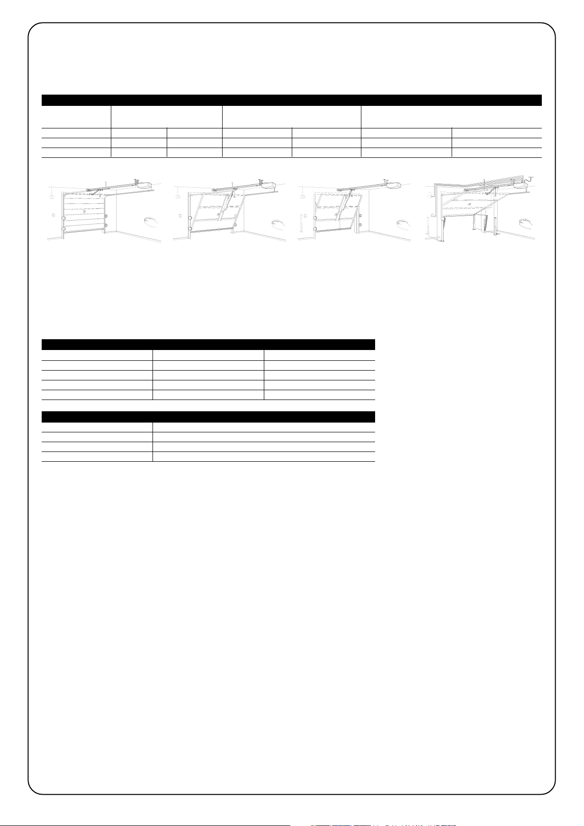
SPIN is a range of gearmotors designed for the automation of sectional doors and, in combination with accessory SPA5 (supplied separately), protruding or non-protruding spring or counterweight overhead doors.
SPIN operates with electric power. In the event of a power failure, the
gearmotor can be released in order to move the door manually.
The products described in tables 1 belong to the SPIN range.
* see paragraph “4.5 radio receiver” for the types of transmitters that can used.
1) Warnings
Important instructions for installation safety
Incorrect installation may cause serious injury.
Carefully follow all installation instructions.
This manual contains important information regarding safety; before you
start installing the components, it is important that you read all the information contained herein. Store this manual safely for future use.
In this manual when all data, warnings and other information related to
all products are stated, the range name “SPIN”. The description of individual products can be found in chapter “2 Product description”
Considering the hazards that may exist during the installation and operation of SPIN, installation must be carried out in strict compliance with
current legislation, standards and regulations. This chapter provides
details of general warnings. Other, more specific warnings are detailed in
Chapters “3.1 Preliminary Checks” and “5 Testing and commissioning”.
According to the most recent European legislation, the
production of automatic doors or gates is governed by the
provisions listed in Directive 98/37/EC (Machine Directive)
and, more specifically, to provisions: EN 12445; EN 12453 and
EN 12635, which enable manufacturers to declare the presumed conformity of the product.
Please access “www.niceforyou.com” for further information, and guidelines for risk analysis and how to draw up the Technical Documentation.
• This manual has been especially written for use by qualified fitters.
Except for the enclosed specification “Instructions and Warnings for
Users of the SPIN gearmotor” which is to be removed by the installer,
none of the information provided in this manual can be considered as
being of interest to end users!
• Any use or operation of SPIN which is not explicitly provided for in
these instructions is not permitted. Improper use may cause damage
and personal injury.
• Risk analysis must be carried out before starting installation, to include
the list of essential safety requisites provided for in Enclosure I of the
Machine Directive, indicating the relative solutions employed. N.B. Risk
analysis is one of the documents included in the “Technical Documentation” for this automation.
• Check whether additional devices are needed to complete the
automation with SPIN based on the specific application requirements
and dangers present. The following risks must be considered: impact,
crushing, shearing, dragging, etc. as well as other general dangers.
• Do not make modifications to any components unless such action is
specified in this manual. Operations of this type are likely to lead to
malfunctions. NICE disclaims any liability for damage resulting from
modified products.
• During installation and use, ensure that solid objects or liquids do not
penetrate inside the control unit or other open devices. If necessary,
please contact the NICE customer service department; the use of
SPIN in these conditions can be dangerous.
• The automation system must not be used until it has been commissioned as described in chapter 5: “Testing and commissioning”.
• The packing materials of SPIN must be disposed of in compliance with
local regulations.
• If a fault occurs that cannot be solved using the information provided
in this manual, refer to the NICE customer service department.
• In the event that any automatic switches are tripped or fuses blown,
you must identify the fault and eliminate it before resetting the switches or replacing fuses.
• Disconnect all the power supply circuits before accessing the terminals
inside the SPIN cover. If the disconnection device is not identifiable,
post the following sign on it: “WARNING: MAINTENANCE WORK IN
PROGRESS”.
!
!
2) Product description
1
Model: Gearmotor Guide Radio receiver Radio Transmitter
SPIN10KCE SN6011 3x1m Incorporated FLO2R-S*
SPIN11KCE SN6011 3m Incorporated FLO2R-S*
Table 1: Description of the SPIN components
Page 4
4
2.1) Operating limits
Chapter 8 “Technical Characteristics” provides the data needed to determine whether the products of the SPIN line are suitable for the intended application.
The structural characteristics of the SPIN products make it suitable for use on sectional and overhead doors within the limits shown in Tables
2, 3 and 4.
The measurements in table 2 are guideline only and can be used as a general estimate only. The effective suitability of SPIN for automating
a specific door depends on the degree of door leaf balancing, guide friction and other aspects, including occasional phenomena such as
wind pressure or the presence of ice, which could obstruct leaf movement.
To establish effective conditions, the force required to move the leaf throughout its stroke must be measured, to ensure that this value does
not exceed the “rated torque” specified in chapter “8 Technical specifications”; also, to calculate the number of cycles/hour and consecutive
cycles, the data in tables 3 and 4 must be taken into account.
The height of the door enables a calculation of the maximum number of cycles per hour and consecutive cycles, while the force required to
move the door enables a calculation of the percentage of cycle reduction; for example, if the leaf height is 2.2 m this would enable 12 cycles
per hour and 6 consecutive cycles, but if a force of 250N is required, these would have to be reduced to 70%, resulting therefore in 8 cycles
per hour and around 4 consecutive cycles.
To avoid overheating, the control unit has a limiter that is based on the motor operation and duration of cycles, and trips when the maximum
limit is exceeded.
Note: 1Kg = 9.81N, for example, 500N = 51Kg
Model: SECTIONAL door OVERHEAD door, non-protruding OVERHEAD door, protruding (with accessory
(with accessory SPA5) SPA5) or with springs (without SPA5)
Height Width Height Width Height Width
SPIN10KCE 2.4m 3.7m 2.2m 3.5m 2.8m 3.5m
SPIN11KCE 2.4m 3.7m 2.2m 3.5m 2.8m 3.5m
Table 2: SPIN gearmotor operating limits
Leaf height Max. no. of cycles/hour
Max. no. of consecutive cycles
Max. 2 16 8
2÷2,5 12 6
2,5÷3 10 5
3÷3,5 8 4
Table 3: limits related to leaf height
Force required to move leaf N
Cycle reduction percentage
Max. 200 100%
200÷300 70%
300÷400 25
Table 4: limits in relation to force required to move door leaf
Page 5

5
GB
2.2) Typical system
Figure 2 shows a typical system for automating a sectional door.
2
1 SPIN
2 Photocells
3 Photocells on post (fig. 3)
4 Main edge
5 Flashing light with incorporated
aerial
6 Key-operated selector switch
7 Radio-transmitter
Figures 3 and 4 show typical installations of a protruding and non-protruding overhead door.
For installations on overhead doors, the accessory SPA5 is required.
!
3 4
5
6
C
B
A
2
2
4
B
B
D
7
1
3
2.3) List of cables
Figure 3 shows the cables needed for the connection of the devices
in a typical installation; Table 5 shows the cable characteristics.
The cables used must be suitable for the type of installation. For example, an H03VV-F type cable is recommended for indoor applications
!
Note 1: A single 4x0.5mm2cable can be used instead of two 2x0.5mm2cables.
Note 2: special devices which enable connection even when the leaf is moving must be used to connect edges to the door.
Connection Cable type Maximum length allowed
A: Flashing light with aerial N°1 cable 2x0,5mm
2
20m
N°1 RG58 type shielded cable 20m (recommended less than 5 m)
B: Photocells N°1 2x0,25mm2cable for TX 30m
N°1 4x0.25mm2cable for RX 30m
C: Key-operated selector switch N°2 2x0,5mm2cables (note 1) 50m
D: Primary sensitive edge N°1 2x0,5mm2cable (note 2) 30m
Table 5: list of cables
B
Page 6

6
3.1) Preliminary checks
Before proceeding with the installation of SPIN you must:
• Verify and ensure after installation that no door parts obstruct pub-
lic roadways or pavements.
• Check that all the materials are in excellent condition, suitable for
use and that they conform to the standards currently in force.
• Make sure that the structure of the gate is suitable for automation.
• Make sure that the force and dimensions of the door fall within the
specified operating limits provided in chapter “2.1 Operating limits”.
• Check that the static friction (that is, the force required to start the
movement of the leaf) is less than half the “maximum torque”, and
that the dynamic friction (that is, the force required to keep the leaf
in movement) is less than half the "nominal torque”. Compare the
resulting values with those specified in Chapter 8 “Technical Characteristics”. The manufacturer recommends a 50% margin on the
force, as unfavourable climatic conditions may cause an increase
in the friction.
• Make sure that there are no points of greater friction in the open-
ing or closing travel of the door.
• Make sure that the mechanical stops are sturdy enough, and that
there is no danger of door derailing.
• Make sure that the door is well balanced: it must not move by itself
when it is placed in any position.
• Make sure that the mounting positions of the various devices (pho-
tocells, keys, etc.) are protected from impacts and that the mounting surfaces are sufficiently sturdy.
• Make sure that the minimum and maximum clearances specified
in fig. 5 and 6 are observed.
• Check and ensure that the manual release is fitted at a maximum
height of 1.8 m.
• Components must never be immersed in water or other liquids.
• Keep all components of SPIN away from heat sources and open
flames; these could damage the components and cause malfunctions, fire or dangerous situations.
• If the door includes an access door, make sure that it does not
obstruct normal travel. Mount a suitable interlock system if necessary.
• If the door to be automated is an overhead type, check the dis-
tance [E] in Figure 7, i.e. the minimum distance between the upper
side of the guide and the maximum point reached by the upper
edge of the door. Otherwise SPIN cannot be installed.
• Connect SPIN only to a power supply line equipped with safety
grounding system.
• The power supply line must be protected by suitable magneto-
thermal and differential switches.
7
3.2) Fitting SPIN
Fixture of the SPIN gearmotor comprises 3 stages.
• Guide assembly (see paragraph 3.2.1 for guides supplied with
SPIN10KCE and paragraph 3.2.2 for guide SNA11)
• Mounting the gearmotor to the guide (see paragraph 3.2.3)
• Mounting the gearmotor to the ceiling (see paragraph 3.2.4)
The installation of SPIN must be carried out by qualified
personnel in compliance with current legislation, standards and regulations, and the directions provided in this
manual.
!
3) Installation
5
6
200mm
300mm
380mm
E 65÷300 mm
C 2970mm D 380mm
B 0÷400mm
A 40÷400mm
200mm
Page 7

7
GB
B
3.2.1) Assembly of guide supplied with SPIN10KCE
The guide that is supplied with SPIN10KCE must be assembled as follows:
1. Referring to figure 8, remove the belt tensioner device (8a); insert one end of the belt into the pulley (8b); reintroduce the belt tensioner
device into the guide (8c).
4. Position both ends of the belt into all of the shaped slots of the lower carriage (C). Secure the ends of the belt with the 2 screws (V4.2x9.5)
and 2 washers (R05), as in figure 11.
5. Fix the belt guide (D) to the upper carriage (E) with the V6x18 screw and related M6 nut, as in figure 12.
6. Insert the upper carriage (E)into the lower carriage (C) and place the entire carriage assembly inside the guide, as in figure 13.
7. With the aid of a hammer, assemble the three pieces of the guide engaging them into the connection brackets (F) with force, as in fig-
ures 14 and 15.
Important: the guides must slide into the brackets until they click into position.
8. Carefully position the belt into the guide, making sure that it is not twisted.
9. Fix the head (B) into the free end of the guide with force, as in figure 16.
10.Finally, tension the belt with the adjustment screw (H) of the belt tensioner device, as in figure 17.
Warning: the gearmotor could break if the belt is too taut and if it is too slack, it could cause unpleasant noise.
11 12 13
C
14 16 17
H
D
E
E
C
8A 8B 8C
10
A
B
9
A
A
2. Pass the same end of the belt through the head (B), as in figure 9.
Note: Make sure that the belt is correctly positioned: it must be with the teeth facing inwards, straight and without twists.
3. Turn the lower section of the carriage so that the grooves correspond with the two ends of the belt, as in figure 10.
F
15
Page 8

8
3.2.2) SNA11 guide assembling
The guide SNA11 guide is already assembled. The only operation
required is tensioning the belt by means of the M8 nut (H), as shown
in figure 17, until it is sufficiently taut.
3.2.3) Mounting the gearmotor to the guide
1. Join the SPIN gearmotor with the guide head (B); then secure by means of the four V6.3x38, screws, as shown in figure 18.
2. The motor can be rotated in three different positions, as shown in figure 19.
18 19
3.2.4) Fissaggio del motoriduttore al soffitto
1. On the basis of distances A and B in figure 5, trace the two fixing points of the front guide bracket at the centre of the door. On the basis
of the type of support surface, the front bracket can be fixed with rivets, plugs or screws (figures 20, 21). If distances A, and B (figure 5)
are sufficient, the bracket can be fixed directly onto the ceiling, as shown in figure 22.
2. After drilling the holes in the relative points, leaving the gearmotor on the ground, lift the guide from the front section and secure by means
of two screws, plugs or rivets, according to the installation surface.
3. Secure the brackets (I) by means of the M6x15 screws (L) and nuts M6 (M) selecting the hole most suited to ensure distance B, as shown
in figure 23.
4. Using a ladder, lift the gearmotor until the brackets are touching the ceiling. Trace the drilling points and then return the gearmotor to the
ground, as shown in figure 24.
20 21 22
23 24
L
M
I
B
Page 9

9
GB
5. Drill at the outlined points and then, using a ladder, lift the gearmotor until the brackets are placed against the drilled holes and secure by
means of screws and plugs suited to the support surface, as shown in figure 25.
6. Ensure that the guide is perfectly horizontal, then cut off the excess section of the brackets with a saw, as shown in figure 26.
7. With the door closed, pull the cord to release carriage (E), as shown in figure 27.
8. Slide the carriage until the leaf connecting bracket (D) on the upper edge of the door is perfectly perpendicular to the guide (G). Then
secure the leaf connecting bracket (D) with rivets or screws, as shown in figure 28. Use screws or rivets suited to the leaf material, and
ensure that they are able to withstand the maximum force required for leaf opening and closing.
9. Loosen the screws of the two mechanical stops, then move the front mechanical stop (O) in front of the carriage, as shown in figure 29.
Push the carriage in the closing direction and, on reaching the position, tighten the screw (N) fully down.
10.Manually open the door to the required opening position, move the rear mechanical stop (Q) next to the carriage, as shown in figure 30
and tighten the screw (P) fully down.
11.Try to move the door manually. Ensure that the carriage slides easily without friction on the guide and that manual movement does not
require excessive force.
25 26
27 28
29 30
E
G
D
O
N
Q
P
3.3) Installation of the Various Devices
If other devices are needed, install them following the directions provided in the corresponding instructions. Check this in paragraph “3.5
Description of electrical connections” and the devices which can be
connected to the SPIN in Figure 2.
Page 10

10
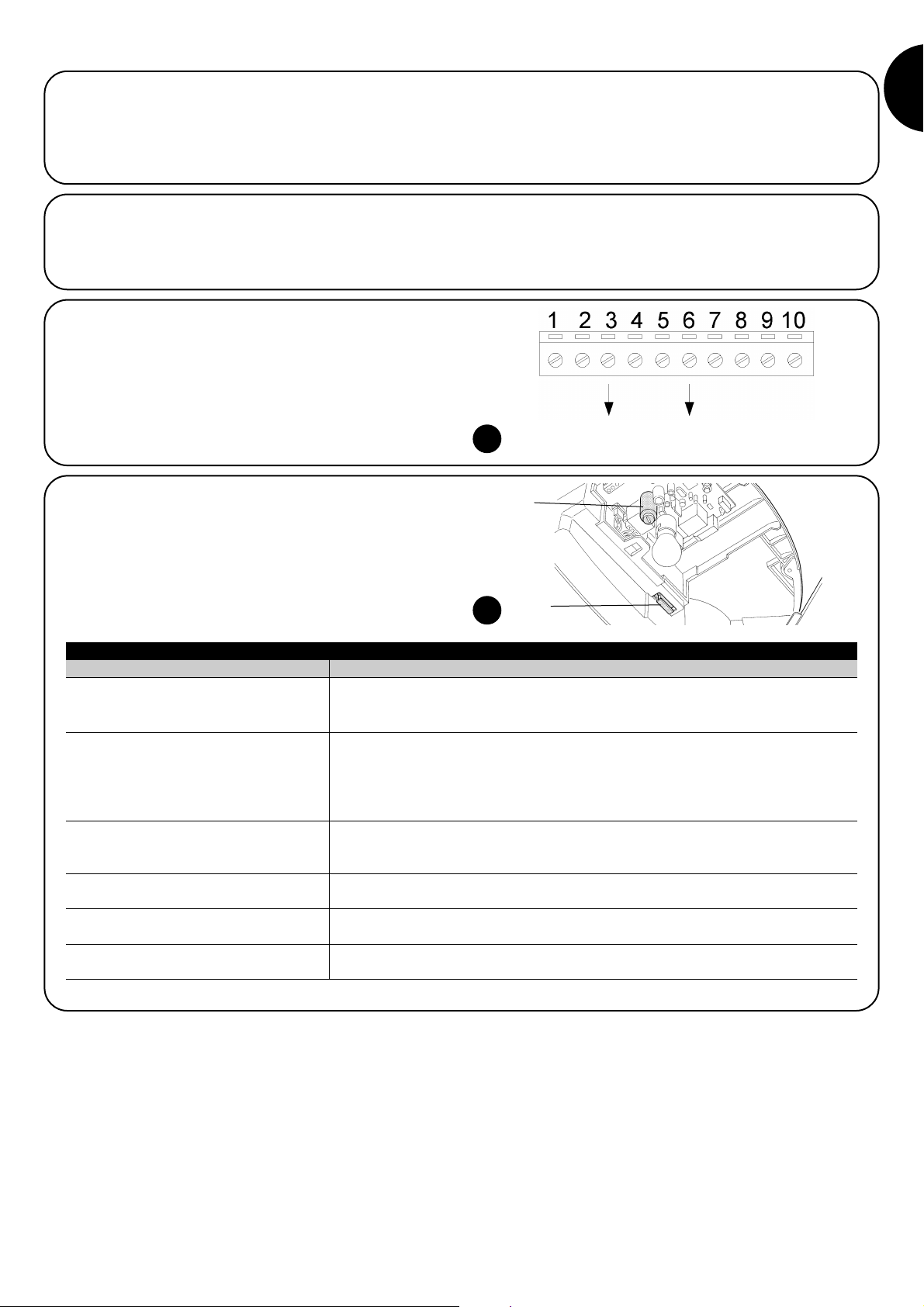
3.4) Electrical connections
Before you proceed to make any electrical connections
make sure that the power supply is disconnected.
1. Open the protection cover in order to access the electronic con-
trol unit of the SPIN. To do this, press the side and rotate as
shown in figure 31.
2. Insert all the connection cables towards the various devices
through the hole, leaving a length of 20÷30 cm longer than necessary. See Table 5 for information regarding the type of cables
and Figure 2 for the connections.
3. Connect up the cables according to the diagram in Figure 33.
!
31 32
33
LUCYB
MOSE
Page 11
11
GB
The manufacturers recommend you unhook the carriage and position the leaf at approximately half travel before starting the checking
and start up phase of the automation. This will ensure the leaf is free
to move both during opening and closure.
4) Final checks and start up
4.1) Power Supply Connection
To power SPIN just insert the plug in a power outlet. If necessary, use
a commercial adapter if the plug on the SPIN unit does not correspond to the socket available.
Never cut or remove the cable supplied with SPIN.
If not already available, the power socket for SPIN connection must be made by qualified and experienced personnel in strict observance of current legislation, standards and regulations.
The power supply line must be protected from short circuits and ground leakage; a device must be provided to
enable the disconnection of the power supply during the
installation and maintenance of SPIN (the plug with outlet
are suitable for this purpose).
As soon as SPIN is energized, you should check the following:
1. Make sure that the “OK” LED flashes regularly, with about one
flash per second.
2. Check that the motor does not control the movement of the door
and that the courtesy light is off.
If the above conditions are not satisfied, you should immediately
switch off the power supply to the control unit and check the electrical connections more carefully.
For more useful information about finding and analysing failures see
also chapter “7.6 Troubleshooting”
!
3.5) Description of the electrical connections
The following is a brief description of the electrical connections; for further information please read “7.3 Adding or Removing Devices” paragraph.
Terminals Function Description
1 – 2 Aerial connection input for the radio receiver aerial. The aerial is incorporated in LUCY B; alternatively
an external aerial can be used or leave a section of wire already present on the terminal, to serve
as an aerial.
3 – 4 Step-by-step input for devices which control movement. It is possible to connect “Normally Open” devices
up to this input.
5 – 6 Stop input for the devices which block or eventually stop the manoeuvre in progress. Contacts like
“Normally Closed”, “Normally Open” or constant resistance devices can be connected up
using special procedures on the input. Please refer to Paragraph “7.3.1 STOP Input” for
further information about STOP.
3 - 7 Photo Input for safety devices such as photocells. Cut-in during closure, reversing the manoeuvre.
“Normally closed “ type contacts can be connected. Further PHOTO information on the can be
seen in paragraph “7.3.2 PHOTO input”
6 – 8 Phototest Whenever a manoeuvre is begun, the relative safety devices are checked and only if everything is in
order will the manoeuvre start.
All this is only possible if a special configuration of the connections is used; in practice, the “TX”
photocell transmitters are powered separately from the “RX” receivers. Please refer to Paragraph
“7.3.2 PHOTO Input” for further information about the connection.
9 – 10 Flashing light a NICE “LUCY B” flashing light can be connected on this output with a car type 12 V 21 W lamp.
During the manoeuvre the unit flashes at intervals of 0.5 s.
Page 12

12
4.2) Recognition of the door opening and closing
positions
The control unit must be made to recognize the opening and closing
positions of the door. In this phase, the door stroke from the closing
mechanical stop to the opening mechanical stop is detected. In
addition to position, the STOP input configuration is detected and
memorised in this phase as well as the existence or non-existence
of the PHOTO input “Phototest”.
1. Ensure that the drive belt is correctly tensioned and that the two mechanical stops are fully secured.
2. Engage the carriage.
3. Press keys []and [ Set ] and hold them down.
4. Release the keys when the manoeuvre starts (after approx. 3 s)
5. Wait for the control unit to complete the recognition stage: closing, opening and closing again of the door.
6. Push the [Step-by-Step] key to perform a complete opening manoeuvre.
7. Push the [Step-by-Step] key to close.
During these manoeuvres, the control unit memorises the force required for opening and closing.
If at the conclusion of the self-learning process the L2 and L3 flash, it means that an error has occurred; see paragraph 7.6 “Troubleshooting”.
It is important that these manoeuvres are not interrupted, e.g. by a STOP command.
If this occurs, the learning process described in point 1 must be repeated.
The recognition stage of the positions, and of the STOP and PHOTO input configuration can be repeated again at any time, even after the
installation (for example, if one of the mechanical stops is removed); just repeat the procedure starting from step
During the position search process, if the belt is not sufficiently tensioned, it may slip on the pinion. If this occurs,
press the [Stop] key to interrupt self-learning; tension the belt by tightening the M8 nut (D) as shown in figure 11, then
repeat self-learning from point 1.
Self-learning of the door opening and closing positions is only possible after the radio transmitter memorisation and
deletion time interval has elapsed (see paragraph 4.5 Radio receiver).
!
!
34
4.3) Checking door movements
On completion of the recognition of the opening and closing positions, it is advisable to carry out a number of manoeuvres in order to
check the door travels properly.
1. Press the [Step-by-Step] key to open the door. Check that
door opening occurs regularly, without any variations in speed;
the door must only slowdown and stop when it is between 30
and 20 cm from the opening mechanical stop. Then, at 2÷3 cm
from the mechanical opening stop the limit switch will trigger.
2. Press the [Step-by-Step] key to close the door. Check that door
closing occurs regularly, without any variations in speed; the door
must only slowdown and stop when it is between 30 and 20 cm
from the closing mechanical stop. A brief opening manoeuvre is
then performed to release belt tension.
3. During the manoeuvre, check that the flashing light (if any) flashes at a speed of 0.5 seconds on and 0.5 seconds off.
4. Open and close the gate several times to make sure that there
are no points of excessive friction and that there are no defects in
the assembly or adjustments.
5. Check that the fastening of the gearmotor, the guide and the
mechanical stops are solid, stable and suitably resistant, even if
the door accelerates or decelerates sharply.
4.4) Pre-set functions
The SPIN control unit has a number of programmable functions. These
functions are set to a configuration which should satisfy most automations. However, the functions can be altered at any time by means of a
special programming procedure. Please refer to paragraph “7.2 Programming” for further information about this.
4.5) Radio receiver
A radio receiver is incorporated in the control unit of SPIN for remote
control, operating at a frequency of 433.92 MHz compatible with the
following types of transmitter:
Since the type of coding is different, the first transmitter that is introduced also determines the type introduced afterwards. Up to 160
transmitters can be memorised.
Memorisation and deletion of transmitters must be performed within the first 10 seconds after powering up the
unit. In this time interval, the control unit key [RADIO] is
used for radio memorisation and deletion functions. 10
seconds after the last flash of led L1 or after the last key
is pressed, the key is disabled and led L1 is dedicated to
programming. The courtesy light flashes once to indicate
the end of the interval in which radio memorisation functions are enabled.
FLO FLO1 – FLO2 – FLO4
VERY VE
FLOR FLOR1 – FLOR2 – FLOR4
VERY VR
ERGO1 – ERGO4 – ERGO6
PLANO1 – PLANO4 – PLANO6
OPERA range transmitters
SMILO SM2 – SM4
Table 6: Transmitters
Page 13

13
GB
1 “Step-by-step” command
2 “Partial opening” command
3 “Open” command
4 “Close” command
Table 8: commands available in Mode II
4.5.1) Memorization of Radio Transmitters
Each radio transmitter is recognised by the radio receiver by means of a “code” which is different from that of any other transmitter. A “memorisation” phase must therefore be performed in order to allow the receiver to recognise each single transmitter. Transmitters can be memorised in 2 modes:
Mode I: in this mode the function of the transmitter keys is fixed and
each key corresponds to the command in the control unit shown in
Table 7; a single memorisation phase is carried out for each transmitter, during which all the transmitter keys are memorised. It doesn’t matter which key is pressed and just one memory sector is occupied. A transmitter can normally only control a single automation in
Mode I.
Mode II: In this mode, each transmitter key can be associated with
one of the 4 possible control unit commands shown in Table 8; only
one key is memorised for each stage, namely the one which was
pressed during memorisation. One memory section is occupied for
each key.
In Mode II, different keys on the same transmitter can be used in
order to give the same automation more than one command or to
control more than one automation. For example, in Table 9, only
automation “A”, is controlled, and the T3 and T4 keys are associated with the same command. Alternatively, three automations are
controlled in the example shown in Table 10, namely “A” (keys T1
and T2), “B” (key T3) and “C” (key T4).
Since the memorization procedures are timed (10s),
you must read the instructions in the following paragraphs
before you proceed with their execution.
!
T1 Key “Step-by-step” command
T2 Key “Partial opening” command
T3 Key “Open” command
T4 Key “Close” command
Table 7: Memorisation mode I
T1 Key “Open” command Automation A
T2 Key “Close” command Automation A
T3 Key “Partial opening” command Automation A
T4 Key “Partial opening” command Automation A
Table 9: 1st example of memorization in Mode II
T1 Key “Open” command Automation A
T2 Key “Close” command Automation A
T3 Key “Step-by-step” command Automation B
T4 Key “Step-by-step” command Automation C
Table 10: 2nd example of memorization in Mode II
Note: single-channel transmitters only have a T1 key, two channel
transmitters only have T1 and T2 keys.
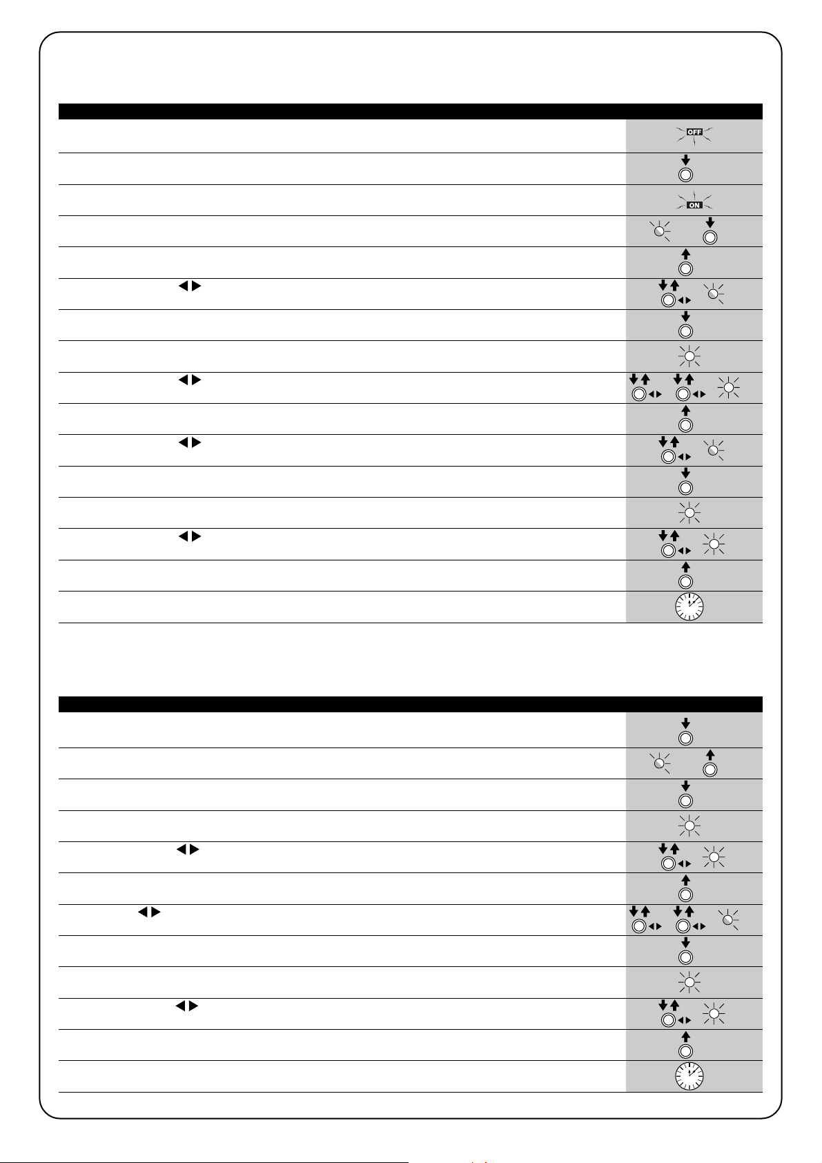
1. Press the radio key on the control unit and hold it down (approx. 4 s)
4s
2. Release the key when the radio LED on the control unit lights up
3. Within 10s, press any key on the radio transmitter to be memorized and hold it down for at least 3s
3s
4. If the memorization procedure is successful, the radio LED on the control unit will flash 3 times.
x3
If there are other transmitters to memorise, repeat step 3 within another 10s seconds.
The memorisation phase finishes if no new codes are received for 10 seconds.
Table 11: to memorize a transmitter in mode I Example
4.5.2) Memorization Mode I
35
1. Press the radio key on the control unit as many times as the number corresponding to the desired
command, according to the table 8 1....4
2. Make sure that the radio LED on the control unit makes as many flashes as the number corresponding
to the desired command 1....4
3. Within 10s, press any key on the radio transmitter to be memorized and hold it down for at least 3s
3s
4. If the memorization procedure is successful, the LED on the receiver will flash 3 times.
x3
If there are other transmitters to memorise for the same type of command, repeat step 3 within another 10 seconds.
The memorisation phase finishes if no new codes are received for 10 seconds.
Table 12: to memorize the key of a transmitter in mode II Example
4.5.3) Memorization Mode II
Page 14

14
1. Press the key on the new radio transmitter and hold it down for at least 5s, then release it.
5s
2. Press the key on the previously memorized transmitter slowly 3 times.
1s 1s 1s
3. Press the key on the new radio transmitter once slowly.
1s
At this point the new radio transmitter will be recognized by the receiver and will assume the characteristics of the previously memorized
one. If there are other transmitters to be memorized, repeat all the steps above for each new transmitter.
Table 13: for the “Remote” memorization of a transmitter Example
4.5.4) “Remote” memorization
A new radio transmitter can be memorized without directly operating
the keys on the receiver. You need to have a pre-memorized operational radio transmitter. The “new” radio transmitter will inherit the characteristics of the old one, i.e. if the old radio transmitter was memorized in Mode 1, the new one will also be memorized in Mode 1. In this
case, during the memorization stage you can press any key on the
transmitters. If, on the other hand, the old transmitter was memorized
in Mode II, the new one will also be memorized in Mode II: you must
press the key on the old transmitter which corresponds to the
desired command, and the key on the new transmitter to which you
wish to associate that command.
Programming via radio may be done on all the receivers
within the range of the transmitter; therefore, only the one
involved in the operation should be kept switched on.
!
Holding the two transmitters, position yourself within the operating range of the automation and perform the following operations:
1. Press the radio key on the control unit and hold it down
2.
Wait until the radio LED lights up, then wait until it goes off, then wait until it has flashed 3 times
x3
3. Release the radio key precisely upon the third flash.
4. If the procedure is successful, after a few moments the LED will flash 5 times.
x5
Table 14: to delete all the radio transmitters Example
4.5.5) Deleting the Radio Transmitters
This is the most important stage in the automation system installation procedure in order to ensure the maximum safety levels.
Testing can also be adopted as a method of periodically checking
that all the various devices in the system are functioning correctly.
Testing of the entire system must be performed by qualified and experienced personnel who must establish which
tests to conduct on the basis of the risks involved, and verify the compliance of the system with applicable regulations, legislation and standards, in particular with all the
provisions of EN standard 12445 which establishes the test
methods for automation systems for gates and doors.
!
5) Testing and commissioning
5.1) Testing
Each component of the system, e.g. safety edges, photocells, emergency stop, etc. requires a specific testing phase. We therefore recommend observing the procedures shown in the relative instruction
manuals.
To test SPIN proceed as follows:
1. Make sure that the provisions contained in chapter 1 «WARNINGS» have been carefully observed.
2. Release the door by pulling the release cord downwards. Check
that the door can be manually manoeuvred with a force no
greater than 225N.
3. Engage the carriage again.
4. Using the selector switch or the radio transmitter, test the opening and closing of the door and make sure that the door moves
in the intended direction.
5. The test should be carried out a number of times to make sure
that the gate moves smoothly, that there are no points of excessive friction and that there are no defects in the assembly or
adjustments.
6. Check the proper operation of all the safety devices, one by one
(photocells, sensitive edges, etc.).
In particular, each time a device is activated the “OK” LED on the
control unit flashes 2 times quickly, confirming that the control unit
recognizes the event.
7. To check the photocells and make sure that there is no interference with other devices, pass a 5 cm diameter, 30 cm long cylinder on the optical axis, first near TX, then near RX and finally at
the mid-point between them and make sure that in all these cases the device is triggered, switching from the active to the alarm
status and vice-versa; finally, that it causes the intended action in
the control unit; for example that it causes the reversal of the
movement during the closing manoeuvre.
8. If the dangerous situations caused by the movement of the door
have been safeguarded by limiting the force impact, the user
must measure the impact force according to EN Standard 12445.
If the adjustment of the “speed” and control of the “motor force”
are used to assist the system for the reduction of the impact
force, try to find the adjustment that gives the best results
Page 15

15
GB
5.2) Commissioning
Commissioning can take place only after all testing phases have been
terminated successfully. It is not permissible to execute partial commissioning or to enable use of the system in makeshift conditions.
1. Prepare and store for at least 10 years the technical documentation for the automation, which must include at least: assembly
drawing of the automation, wiring diagram, analysis of hazards
and solutions adopted, manufacturer’s declaration of conformity
of all the devices installed (for SPIN use the annexed CE declaration of conformity); copy of the instruction manual and maintenance schedule of the automation.
2. Post a permanent label or sign near the door detailing the operations for the release and manual manoeuvre (refer to the figures in
“Instructions and warnings for users of the SPIN gearmotor”).
3. Post a permanent label or sign near the door containing this picture (min. height 60 mm).
4. Post a label on the door providing at least the following data: type
of automation, name and address of manufacturer (person
responsible for the “commissioning”), serial number, year of manufacture and “CE” marking.
5. Prepare the declaration of conformity of the automation system
and deliver it to the owner.
6. Prepare the “Installation instructions and warnings” of the
automation system and deliver it to the owner.
7. Prepare the maintenance schedule of the automation system and
deliver it to the owner; it must provide all directions regarding the
maintenance of all the automation devices.
Before commissioning the automation system inform the owner in
writing regarding dangers and hazards that are still existing (e.g.
in the “Installation instructions and warnings”).
36
This chapter provides information about how to draw up a maintenance schedule, and the disposal of SPIN.
6) Maintenance and Disposal
6.1) Maintenance
The automation must be subjected to maintenance work on a regular basis, in order to guarantee it lasts.
The maintenance operations must be performed in
strict compliance with the safety directions provided in
this manual and according to the applicable legislation
and standards.
If other devices are present, follow the directions provided in the corresponding maintenance schedule.
1. SPIN requires scheduled maintenance work every 6 months or
3,000 manoeuvres after previous maintenance.
2. Disconnect the power supply
3. Check for any deterioration of the components which form the
automation, paying special attention to erosion or oxidation of the
structural parts. Replace any parts which are below the required
standard.
4. Check the wear and tear on the moving parts: belt, carriage, pinions and the door components; if necessary replace them.
Connect the electric power sources up again, and carry out all
the tests and checks described in paragraph 5.1 “Testing”.
!
6.2) Disposal
SPIN is constructed of various types of materials, some of which can
be recycled: steel, aluminium, plastic, electric cables; while others
must be disposed of (batteries and electronic boards).
Some electronic components may contain polluting
substances; do not pollute the environment. Enquire
about the recycling or disposal systems available in compliance regulations locally in force.
1. Disconnect the power supply of the automation system.
2. Disassemble all the devices and accessories, following in reverse
order the procedures described in chapter 3 “Installation”.
3. Wherever possible, separate any parts which can or must be
recycled or disposed of in different ways, e.g. metal parts must
be disposed of separately from plastic ones, as must the electronic cards etc.
4. Sort the various materials and consign them to local licensed
firms for recovery and disposal.
!
Page 16
16
This chapter deals with the options for programming, personalisation, diagnostics and troubleshooting for the SPIN gearmotor.
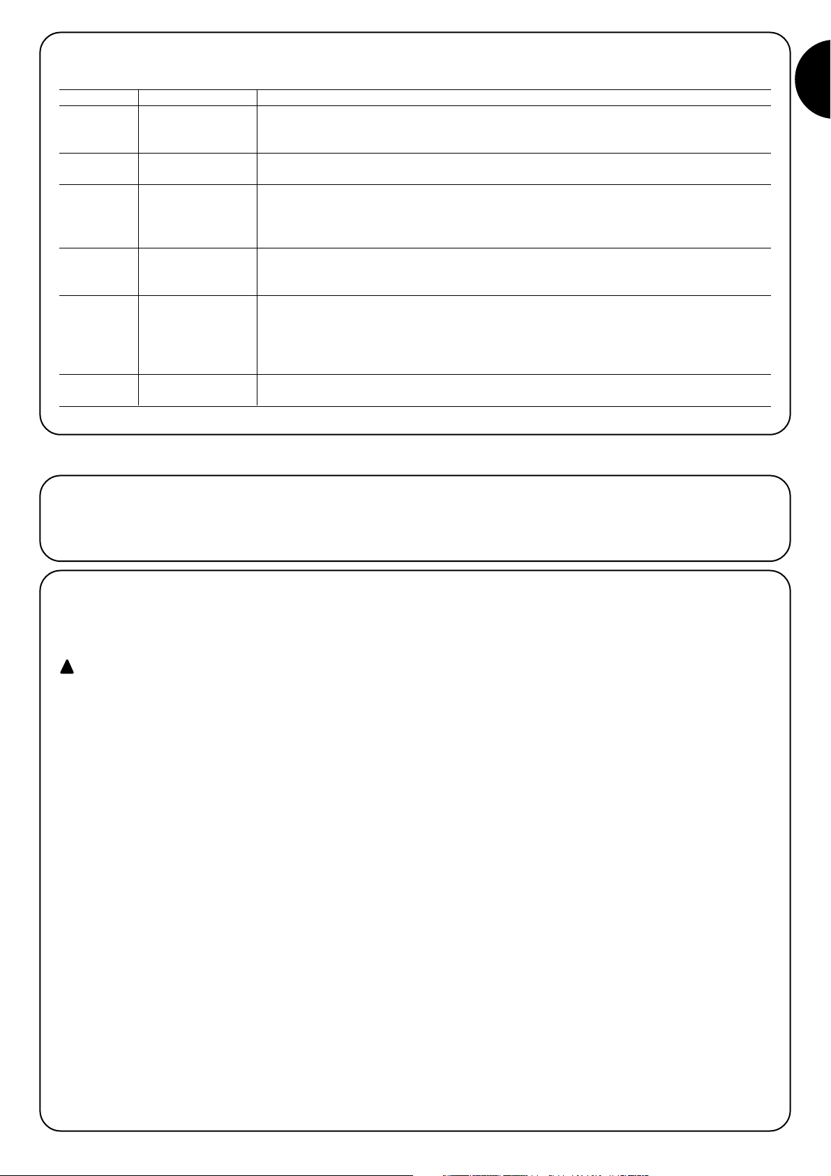
7) Further information
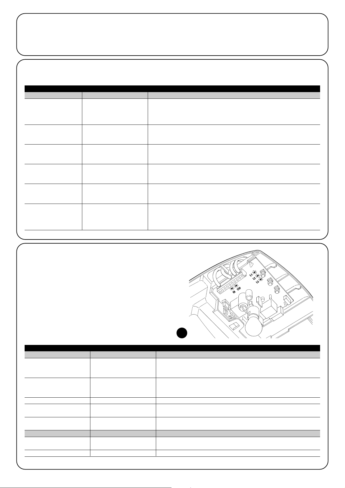
RADIO Within the first 10 seconds after power-up, perform the “RADIO” function to
enable memorisation and deletion of the radio transmitters used with SPIN.
After this time interval, the key is no longer used.
Stop The STOP key stops the manoeuvre; if pressed for more than 5 seconds,
SET it enables entry to programming mode as described below.
SS The SS key enables door opening and closing commands; otherwise this key
can be used to scroll up through the programming steps.
7.1) Programming keys
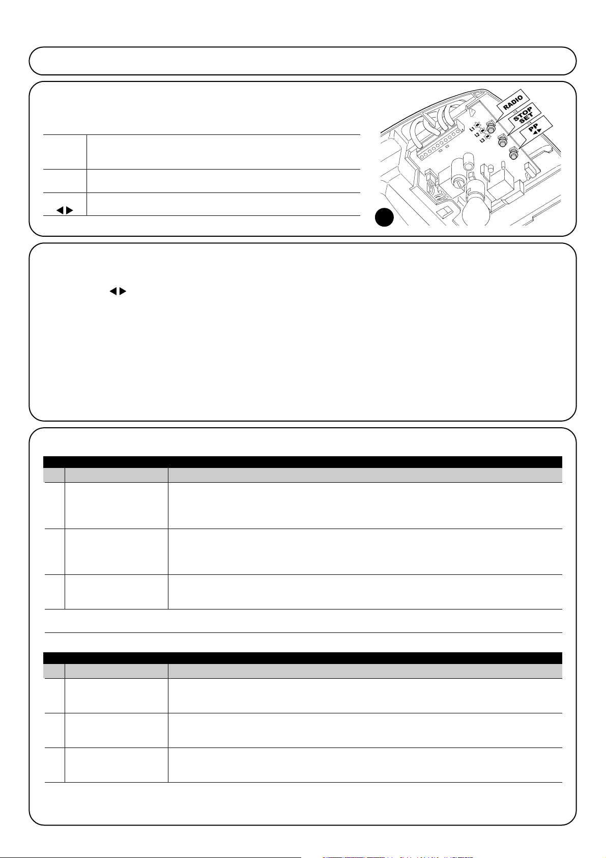
The SPIN control unit is fitted with 3 keys which can be used both for the control of
the unit during testing and the programming procedure:
7.2) Programming
The SPIN control unit is equipped with a number of programmable
functions; function settings are entered by means of the 2 keys on
the control unit: []and [Set] and are displayed by means of 3
leds: L1, L2, L3.
There are two types of programming:
Programming on power-up: This type of programming can be
performed only immediately after switching on SPIN. Press and hold
[Set] during power-up of the control unit to activate this programming mode.
Standard programming: This programming mode can be used at
any time and is activated by pressing and holding [Set].
For both modes, the programming and programmable functions
available are divided into 2 levels:
Level 1: functions settable in ON-OFF mode (enabled or disabled);
in this case leds L1, L2, and L3 indicate a function, if lit the function
is enabled, if off the function is disabled; see Tables 15 and 15a.
Level 2: parameters settable on a scale of values (from 1 to 3); in
this case each led L1, L2, L3 indicates a set value from the possible 3; see Tables 17 and 17a.
37
N° Description Example
L1 Variable Sensitivity This function enables the user to enable or disable sensitivity with which obstacles are detected.
The factory setting of sensitivity is variable (led L1 off): Greater sensitivity in the case of low motor force,
and less sensitivity where the motor force increases. All with the aim of ensuring optimal detection
precision. Variable sensitivity can be disabled, and 3 “fixed” levels of motor force remain (led L1 lit).
L2 Phototest/Electric block This function enables the user to enable output 8 of the terminal board for operation with Phototest or
with an Electric block. The factory setting of output 8 is with the “phototest” function enabled (led L2 off).
Alternatively the output can be programmed on the SPIN control unit for control of an electric block
(led L2 lit).
L3 Partial open This function enables the selection of a long or short partial opening interval. The factory setting for
partial open is long (approx. 1 m, led L3 lit). Alternatively partial open can be set to short (approx. 15cm,
led L3 off).
At the end of the “Programming on power-up” procedure, leds L1, L2 and L3 indicate the status of the functions in “Standard programming” mode.
Table 15: List of programmable functions in “Programming on power-up” mode
7.2.1) Level 1 functions (ON-OFF functions)
N° Description Example
L1 Closing speed This function enables the selection of the motor speed during the closing manoeuvre, from 2 levels:
“high” and “low”. The factory setting is “high” (led L1 lit). Alternatively the function can be disabled to set
the “low” speed (led L1 off).
L2 Opening speed This function enables the selection of the motor speed during the opening manoeuvre, from 2 levels:
“high” and “low”. The factory setting is “high” (led L2 lit). Alternatively the function can be disabled to set
the “low” speed (led L2 off).
L3 Automatic closure This function enables automatic closure of the door after a programmed pause; the default Pause Time
is set at 30 seconds but may be modified to 15 or 60 seconds. The factory setting is “semiautomatic”
as Automatic closure is disabled (led L3 off).
During normal operation of SPIN, leds L1, L2 and L3 are lit or off depending on the status of the associated function in Standard programming mode, for example L3 is lit if the function “Automatic closure” is enabled. L1 also displays the status of the “radio” function in
the first 10 seconds after power-up.
Table 15a: List of programmable functions in “Standard programming” mode
Page 17

17
GB
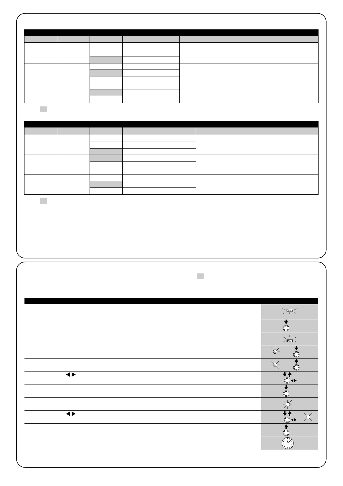
7.2.2) Level 1 programming (ON-OFF functions)
By default level 1 functions are set as shown in tables 15 and 15a, but can be modified at any time as shown in tables 16 and 16a. Take
care during modification procedures, as there is a maximum time interval of 10 seconds between pressing one key and another; otherwise
the system exits the procedure automatically memorising the changes made up to that time.
1. Switch off SPIN (for example by removing fuse F1)
2. Press and hold [Set]
3. Switch on SPIN (for example by inserting fuse F1)
4. Wait for the flashing signal indicating control unit start-up and keep [Set] pressed until L1 starts to
flash (approx. 6s) L1 6s
5. Release the key [Set] when led L1 starts to flash
L1
6. Press key []to move the flashing led to the led associated with the function to be modified
7. Press [Set] to change the status of the function (short flash = OFF; long flash = ON)
8. Wait 10s to exit the programming mode automatically after the maximum time interval.
10s
Note: points 6 and 7 can be repeated during the same programming phase to set other functions to ON or OFF.
Table 16: To modify the ON-OFF functions in “programming on power-up” mode Example
SET
SET
SET
SET
1. Press and hold [Set] for approx. 3s
3s
2. Release the key [Set] when led L1 starts to flash
L1
3. Press key []to move the flashing led to the led associated with the function to be modified
4. Press [Set] to change the status of the function (short flash = OFF; long flash = ON)
5. Wait 10s to exit the programming mode automatically after the maximum time interval.
10s
Note: points 3 and 4 can be repeated during the same programming phase to set other functions to ON or OFF
Table 16a: To modify the ON-OFF functions in “standard programming” mode Example
SET
SET
SET
Page 18
18
Sensitivity
variable
Belt recovery
Closing
slowdown
High
Medium
Low
No recovery
Minimum recovery
Maximum recovery
Short
Medium
Long
7.2.3) LEVEL 2 functions (adjustable parameters)
Table 17: List of level 2 programmable functions in “Programming on power-up” mode
Input leds Parameter Led (level) Value Description
When variable sensitivity is enabled, it can be set to three different activation thresholds. “High” variable sensitivity is most
suited to small size correctly balanced doors.
Sets the belt recovery value. After complete closure of the
door, a very brief opening manoeuvre is activated, settable
with this parameter.
Sets the slowdown time interval during the closing manoeuvre.
Note: “ ” Represents factory settings.
L1
L2
L3
L1
L2
L3
L1
L2
L3
L1
L2
L3
7.2.4) Level 2 programming (adjustable parameters)
By default the settable parameters are set as shown in Tables 17 and 17a with: “ “ but can be modified at any time as shown in Tables
18 and 18a. Take care during modification procedures, as there is a maximum time interval of 10 seconds between pressing one key and
another; otherwise the system exits the procedure automatically memorising the changes made up to that time.
1. Switch off SPIN (for example by removing fuse F1)
2. Press and hold [Set]
3. Switch on SPIN (for example by inserting fuse F1)
4. Wait for the flashing signal indicating control unit start-up and keep [Set] pressed until L1 starts to flash
(approx. 6s) L1 6s
5. Release the key [Set] when led L1 starts to flash
L1
6. Press key []to move the flashing led to the “input led” associated with the parameter to be
modified
7. Press and hold [Set] during steps 5 and 6
8. Wait approx. 3s after which the led associated with the current level of the parameter to be modified
will light up 3s
9. Press key []to move the led associated with the parameter value.
10. Release [Set]
11. Wait 10s to exit the programming mode automatically after the maximum time interval.
10s
Note: Points 6 to 10 can be repeated during the same programming phase to modify other parameters
Table 18: To modify the adjustable parameters in “programming on power-up” mode Example
SET
SET
SET
SET
Motor force
SS function.
Pause Time
Low
Medium
High
Open, Stop, Close, Open
Open, Stop, Close, Stop
Apartment block
15 seconds
30 seconds
60 seconds
Table 17a: List of level 2 programmable functions in “Standard programming” mode
Input leds Parameter Led (level) Value Description
Sets the maximum force generated by the motor to
move the door.
Adjusts the sequence of commands associated with
the SS input or the 1st radio command (see tables 7
and 8).
Adjusts the pause time, i.e. time before automatic reclosure. Is effective only if automatic closure is enabled
Note: “ ” Represents factory settings.
All parameters can be adjusted as required without any contraindications, only the “Motor force” setting may require special attention:
• Use of high force values are not recommended to compensate for the fact that the leaf has anomalous points of friction; excessive force
may impair the safety system and damage the leaf.
• If the “Motor force control” is used in support of the system for impact force reduction, after each adjustment the force measurement pro-
cedure must be performed, as envisaged by standard EN 12445.
• Wear and atmospheric conditions influence movement of the gate; force settings should be checked periodically.
L1
L2
L3
L1
L2
L3
L1
L2
L3
L1
L2
L3
SET
Page 19

19
GB
1. Press and hold [Set] for approx. 3s
3s
2. Release the key [Set] when led L1 starts to flash
L1
3. Press key []to move the flashing led to the “input led” associated with the parameter to be
modified
4. Press and hold [Set] during steps 5 and 6
5. Wait approx. 3s after which the led associated with the current level of the parameter to be modified
will light up
6. Press key []to move the led associated with the parameter value.
7. Release [Set]
8. Wait 10s to exit the programming mode automatically after the maximum time interval.
10s
Note: Points 3 to 7 can be repeated during the same programming phase to modify other parameters
Table 18a: To modify the adjustable parameters in “standard programming” mode Example
SET
SET
SET
SET
7.2.5) LEVEL 1 programming examples (ON-OFF functions)
This example shows the sequence of operations required to change the factory setting of the functions to deactivate the function of “Variable Sensitivity” (L1) and activate “Short Partial Open” (L3).
1. Switch off SPIN (for example by removing fuse F1)
2. Press and hold [Set]
L1
3. Switch on SPIN (for example by inserting fuse F1)
4. Wait for the flashing signal indicating control unit start-up and keep [Set] pressed until L1 starts to flash
(approx. 6s) L1 6s
5. Release [Set]
6. Press [Set] once to change the status of the function associated with L1 (Variable Sensitivity) led L1
now emits long flashes L1
7. Press []twice to move the flashing led onto led L3
L3
8. Press [Set] once to change the status of the function associated with L3 (Partial open) led L3 now
emits long flashes L3
9. Wait 10s to exit the programming mode automatically after the maximum time interval
10s
On standby to exit programming mode, leds L1 and L3 must remain lit to indicate that the functions “Variable Sensitivity disabled” and “Short
Partial Open” are active.
Table 19: Example of LEVEL 1 programming in “Programming on power-up” mode Example
SET
SET
SET
This example shows the sequence of operations required to change the factory setting of the functions to activate the functions of “High
opening speed” (L2) and “Automatic Closure” (L3).
1. Press and hold [Set] for approx. 3s
3s
2. Release the key [Set] when led L1 starts to flash
L1
3. Press the key [] once to move the flashing led onto led L2
L2
4. Press [Set] once to change the status of the function associated with L2 (Opening speed) led L2 now
emits long flashes L2
5. Press the key []once to move the flashing led onto led L3
L3
6. Press [Set] once to change the status of the function associated with L3 (Automatic closure) led L3
now emits long flashes L3
7. Wait 10s to exit the programming mode automatically after the maximum time interval
10s
At the end of these operations leds L2 and L3 must remain lit to indicate that the functions “High opening speed” and “Automatic closure” are
enabled.
Table 19a: Example of LEVEL 1 programming in “Standard programming” mode Example
SET
SET
SET
SET
SET
SET
Page 20
20
7.2.6) Examples of LEVEL 2 programming
This example shows the sequence of operations required to change the factory setting of the parameters and set the functions of “Belt
Recovery” to no recovery (input on L2 and level on L1) and set “Closing slowdown” to long (input on L3 and level on L3).
1. Switch off SPIN (for example by removing fuse F1)
2. Press and hold [Set]
3. Switch on SPIN (for example by inserting fuse F1)
4. Wait for the flashing signal indicating control unit start-up and keep [Set] pressed until L1 starts to flash
(approx. 6s) L1 6s
5. Release [Set]
6. Press the key []once to move the flashing led onto led L2
L2
7. Press and hold [Set] during steps 8 and 9
8. Wait approx. 3s until led L2 lights up, indicating the current level of “Belt recovery”
L2 3s
9. Press the key []once to move the illuminated led onto L1, to eliminate “Belt recovery”
L1
10. Release [Set]
11. Press the key []once to move the flashing led onto led L3
L3
12. Press and hold [Set] during steps 13 and 14
13. Wait approx. 3s until led L2 lights up, indicating the current level of “Closing slowdown”.
L2 3s
14. Press the key []once to move the illuminated led onto L3, indicating the new value of
“Closing slowdown”. L3
15. Release [Set]
16. Wait 10s to exit the programming mode automatically after the maximum time interval.
10s
Table 20: Example of LEVEL 2 programming in “Programming on power-up” mode Example
SET
SET
SET
SET
SET
SET
SET
This example shows the sequence of operations required to change the factory setting of the parameters and set the functions of “Motor
Force” to high (input on L1 and level on L3) and increase the “Pause Time” to 60s (input on L3 and level on L3).
1. Press and hold [Set] for approx. 3s
3s
2. Release the key [Set] when led L1 starts to flash
L1
3. Press and hold [Set] during steps 4 and 5
4. Wait approx. 3s until led L2 lights up, indicating the current level of “Motor Force”
L2 3s
5. Press the key []once to move the illuminated led onto L3, indicating the new value of “Motor Force”
L3
6. Release [Set]
7. Press []twice to move the flashing led onto led L3
L3
8. Press and hold [Set] during steps 9 and 10
9. Wait approx. 3s until led L2 lights up, indicating the current level of “Pause Time”.
L2 3s
10. Press the key []once to move the illuminated led onto L3, indicating the new value of “Pause Time”.
L3
11. Release [Set]
12. Wait 10s to exit the programming mode automatically after the maximum time interval.
10s
Table 20a: Example of LEVEL 2 programming in “Standard programming” mode Example
SET
SET
SET
SET
SET
SET
Page 21

21
GB
7.3) Adding or removing devices
Devices can be added or removed at any time on an automation
using SPIN. In particular the inputs STOP and PHOTO can be connected to various types of device as indicated in paragraphs “7.3.1
STOP Input” and 7.3.2 Photocells. The figure shows the wiring diagram for connection of the various devices.
7.3.1) STOP input
STOP is the input that causes immediate shutdown of the movement followed by a brief inversion of the manoeuvre. This input can
be connected to devices with contact types Normally Open (NO),
Normally Closed (NC) or devices with a constant resistance of
8.2KΩ, such as sensitive edges.
The control unit recognises the type of device connected to the
STOP input during the self-learning phase (see paragraph “4.2 –
Learning the door opening and closing positions”); after which a
STOP command is activated whenever a variation with respect to
the learned status is detected.
When set accordingly, more than one device can be connected to
the STOP input, also different from one another:
• Several NO devices can be connected in parallel with no limit to
number.
• Several NC devices can be connected in parallel with no limit to
number.
• Several devices with a constant resistance of 8,2KΩ can be con-
nected “in cascade” with a single terminating resistance of 8,2KΩ
• It is possible to combine two NO and NC contacts, placing them
in parallel, taking care to place a resistance of 8,2KΩ in series with
the NC contact (this also enables the combination of 3 devices:
NO, NC and 8,2KΩ).
If the STOP input is used to connect devices with safety functions, only the devices with a constant resistance
of 8,2KΩ guarantee safety category 3 against faults in
accordance with the standard EN 954-1.
!
Page 22

22
7.3.2) Photocells
The SPIN control unit is equipped with the function “Phototest” which increases the reliability of the safety devices, enabling classification in
category 2 in compliance with the standard EN 954-1 regarding the combination of the control unit and safety photocells.
Each time a manoeuvre is started up, all safety devices are checked and only in the case of positive results can the manoeuvre be started.
If however the test fails (photocell “blinded “ by sun, cables shorted etc) the fault is identified and the manoeuvre is disabled.
For the “phototest” function, a specific connection is required of the photocell transmitters (see fig. 40 and 41).
The control unit recognises the connection in “phototest” mode during the self-learning phase (see paragraph “4.2 Learning the door opening and closing positions”)
• Connection without “Phototest” function (Figure 38 and 39)
Power the transmitters and receivers directly from the control unit services output (terminals 3 - 6).
• Connection without “Phototest” function (Figure 40 and Figure 41):
Power of the receivers comes directly from the services output (terminals 3 - 6), while that of the transmitters is from the “Phototest” output (terminals 8 – 6). The maximum admissible current on the “Phototest” output is 100mA.
If two pairs of photocells are used, which may interfere with the other, activate the synchronisation mechanism as described in the photocell
instructions.
38 39
40 41
7.3.3) Electric block
The factory setting of the “phototest” output is with the “Phototest”
function enabled.
Alternatively the output can be programmed on the SPIN control unit
for control of an electric block. On start-up of each opening manoeuvre, the output is activated for 2 seconds; in this way an electric
block device can be connected. The output is not activated during
the closing manoeuvre and therefore the electric block must have a
provision for mechanical reactivation.
The output can control the electric block directly, but only with loads
of 24Vac – 2W. The output must be interfaced with a relay, as shown
in the figure.
Page 23
23
GB
7.4.1) “Always open” Function
The “Always open” function is a control unit feature which enables
the user to control an opening manoeuvre when the “Step-by-step”
command lasts longer than 3 seconds. This is useful for connecting
a timer contact to the “Step-by-step” input in order to keep the door
open for a certain length of time, for example. This feature is valid
whatever the “Step-by-step” input programming may be (see the
“Step-by-step” properties in table 17).
7.4) Special functions
7.4.2) “Move anyway” Function
If one of the safety devices are out of order or malfunctioning, it is still
possible to control the door in “Man present” mode.
Please refer to the Paragraph “Control with safety devices out of
order” in the enclosure “Instructions and Warnings for users of the
SPIN gearmotor”.
7.5) Connection of other devices
If the user needs to feed external devices such as a proximity reader for transponder cards or the illumination light of the key-operated
selector switch, it is possible to tap power as shown in Figure 42.
The power supply voltage is 24Vac -30% +50% with a maximum
available current of 100mA.
24Vac
42
7.6) Troubleshooting
The following table contains instructions to help you solve malfunctions or errors that may occur during the installation stage or in case
of failure.
43
Table 21: Troubleshooting
Symptoms Probable cause and possible solution
The radio transmitter does not control the
door and the LED on the transmitter does
not light up
The radio transmitter does not control the
door and the LED on the transmitter lights up
No manoeuvre starts and the OK LED fails
to flash
No manoeuvre starts and the flashing light is
off
No manoeuvre starts and the flashing light
flashes a few times
The manoeuvre starts but it is immediately
followed by a reverse run
Check to see if the transmitter batteries are exhausted, if necessary replace them
Check to see if the transmitter has been memorised correctly in the radio receiver.
Check that the emission of the transmitters radio signal is correct by means of this empirical test: push a key and rest the LED on the aerial of a normal radio (ideally an economical
one) that is switched on and tuned in, as close as possible, to 108.5Mhz FM; a slight
crackling sound should be heard.
Check that SPIN is being fed 230 V voltage from the power supply. Check to see if the
fuses F1 and F2 are blown; if necessary, identify the reason for the failure and then replace
the fuses with others having the same current rating and characteristics.
Make sure that the command is actually received. If the command reaches the Step-byStep input, the OK led flashes twice indicating that the command has been received.
Count the flashes and check the corresponding value in table 22.
The selected force could be too low for this type of door. Check to see whether there are
any obstacles; if necessary increase the force.
F2
F1
Page 24
24
OK LED Cause ACTION
STOP LED Cause ACTION
Off
7.7.2) Signals on the control unit
On the SPIN control unit there is a set of LED’s each of which can
give special indications both during normal operation and in case of
malfunctions.
Table 23: LED’s on the control unit’s terminals
Malfunction
Make sure there is power supply; check to see if the fuses are blown; if
necessary, identify the reason for the failure and then replace the fuses with
others having the same characteristics.
On Serious malfunction
There is a serious malfunction; try switching off the control unit for a few
seconds; if the condition persists it means there is a malfunction and the
electronic board has to be replaced.
One flash every second Everything OK Normal operation of control unit
2 Quick flashes
The status of the inputs has
changed
This is normal when there is a change in one of the inputs: Step-by-Step,
STOP, triggering of photocells or the radio transmitter is used
Series of flashes separated by
a second’s pause
Miscellaneous It corresponds to the flashing light or the courtesy signal. See Table 22
Off Activation of the STOP input Check the devices connected to the STOP input
On Everything OK STOP Input active
44
7.7) Diagnostics and Signals
A few devices issue special signals that allow you to recognize the
operating status or possible malfunctions.
7 flashes
1 second’s pause
7 flashes
At the starting of the manoeuvre, one or more photocells do not enable it;
check to see if there are any obstacles.
This is normal when there is an obstacle impeding the closing movement.
7.7.1) Signalling with flashing light and courtesy light
During the manoeuvre the flashing light, if connected, flashes once every second. When something is wrong the flashes are more frequent;
the light flashes twice with a second’s pause between flashes. The courtesy light gives the same diagnostics signals.
Table 22: FLASH flashing light signalling
Quick flashes Cause ACTION
2 flashes
1 second’s pause
2 flashes
Triggering of a photocell
3 flashes
1 second’s pause
3 flashes
Activation of the “motor force”
limiting device
During the movement, the door experienced excessive friction; identify the
cause.
4 flashes
1 second’s pause
4 flashes
Activation of the STOP input During the movement the STOP input was activated; identify the cause
5 flashes
1 second’s pause
5 flashes
Error in the internal
parameters of the electronic
control unit
Wait at least 30 seconds, then try giving a command; if the condition persists it
means there is a serious malfunction and the electronic board has to be
replaced.
6 flashes
1 second’s pause
6 flashes
The maximum manoeuvre
limit/hour has been exceeded
Wait for a few minutes until the manoeuvre limiting device drops to under the
maximum limit.
There is an error in the
internal electric circuits
Disconnect all the power circuits for a few seconds and then try giving a
command again; if the condition persists it means there is a serious fault on the
electronic board or the motor cabling. Check and replace as necessary.
Page 25

25
GB
L1 LED Description
• Function programming in progress.
• If it flashes together with L2 it means that the user must carry out the recognition of the door opening and
closing positions (refer to Paragraph “4.2 Recognition of the door opening and closing positions”).
L3 LED Description
L2 LED Description
Off
Table 24: LED’s on the control unit’s keys
Correct during normal functioning.
Indicates that a radio code that is not in the memory, has been received during normal functioning.
• Function programming in progress.
• Memorising or Deleting the Radio Transmitters
On
It flashes
Off Indicates the slow “Motor speed” during normal functioning.
Indicates the fast “Motor speed” during normal functioning.
• Function programming in progress.
• If it flashes together with L3 it means that the user must carry out the recognition of the door opening and
closing positions (refer to Paragraph “4.2 Recognition of the door opening and closing positions”).
On
It flashes
Off During normal operation the device indicates “Automatic Closing” is inactive.
During normal operation the device indicates “Automatic Closing” is active.On
It flashes
7.8) Accessories
The following optional accessories are available for SPIN. For information on the complete range of accessories, refer to the Nice s.p.a.
product catalogue.
For all versions
• SPA2 Mechanical release with metal cord. For use in systems
which envisage only the automated door as point of access.
For all versions
• SPA5 Oscillating arm. Required if the door to be automated is an
overhead type with springs or counterweights.
Page 26

26
Emergency power supply No
Flashing Light Output For 1 LUCYB flashing light (12V, 21 W)
SPIN Courtesy Light
SPIN/V1 Courtesy Light
12V-21W BA15 socket
12V-21W BA15 socket
Use in acid, saline or potentially explosive
atmosphere
225 x 330 h 100 / 3,3Kg
Nice S.p.a., in order to improve its products, reserves the right to modify their technical characteristics at any time without prior notice. In
any case, the manufacturer guarantees their functionality and fitness for the intended purposes.
All the technical characteristics refer to a room temperature of 20°C (±5°C).
8) Technical characteristics
Ty pe
Technical characteristics: SPIN
Electromechanical gearmotor for the automatic movement of garage doors for residential
use, complete with electronic control unit
Pinion Diameter 9.5 mm, 28 teeth; for guides SNA11 and guides supplied with SPIN10KCE
Model: SN6011
Peak thrust
[corresponds to the force necessary to start
a leaf]
9.9Nm
[550N]
4.95Nm
[275N]
Nominal torque
[corresponds to the force necessary to keep
a leaf moving]
Speed under no load
[corresponds to if “Fast” speed is
programmed]
103 rpm
[0,14m/s]
The control unit enables programming 2 speeds equal to approx. 100% - 60% approx.
Nominal torque speed
[corresponds to if “Fast” speed is
programmed]
52 rpm
[0,07m/s]
Maximum frequency of operating cycles 30 cycles per day (the control unit allows up to the maximum described in tables 3 and 4)
Maximum continuous operating time
3 minutes (the control unit limits the continuous operation up to the maximum described in
tables 3 and 4)
Operating limits
In general, SPIN is suitable for the automation of sectional or overhead doors which remain
within the dimensions stated in table 2 and limits specified in Tables 3 and 4.
Max. absorbed power 200W
Insulation class 1 (a safety grounding system is required)
STOP Input
For normally close or normally open contacts or for constant resistance
8,2KΩ with self-recognition (any variation from the memorized status causes the “STOP”
command)
Step-by-step Input
For normally open contacts (the closing of the contact causes the “STEP-BY-STEP” command)
Radio AERIAL Input 52Ω for RG58 or similar type of cable
Radio receiver Incorporated
SPIN Power Supply
SPIN/V1 Power supply
230Vac (±10%) 50/60Hz.
120Vac (±10%) 50/60Hz.
Programmable functions 6 ON-OFF functions and 6 adjustable functions (see tables 15, 15a and 17, 17a)
Operating temperature -20°C ÷ 50°C
No
Protection class IP 40 use only in indoor or protected environments
Dimensions and weight
Recognition functions
Recognition of the type of “STOP” device (NO or NC contact or 8,2KΩ resistance).
Recognition the door opening and closing positions and calculation of the slowdown and
partial opening points.
Model: Guide in SPIN10KCE SNA11
Type 3-piece profile in galvanised steel single profile in galvanised steel
Guide length 3.15m 3.15m
Guide height 35mm 35mm
Useful stroke 2.6m 2.6m
Belt width 6m 6m
Belt height 6mm 6mm
Resistance to traction 730N 730N
Guide technical characteristics
Page 27

27
GB
Technical characteristics incorporated radio receiver
Type 4 channel receiver for incorporated radio command
Frequency 433.92MHz
Coding Digital Fixed code with 12 Bit code, FLO type
Digital Rolling code with 52 Bit code, FLOR type
Digital Rolling code with 64 Bit code, SMILO type
Transmitter compatibility (1) FLO, VERY VE
FLOR, VERY VR; only single group: ERGO, PLANO,
SMILO
Transmitters memorized Up to 160 if memorized in mode 1
Input impedance 52Ω
Sensitivity better than 0.5µV
Range of the transmitters From 100 to 150 m. The range can vary if there are obstacles or electromagnetic disturbances,
and is affected by the position of the receiving aerial
Outputs /
Operating temperature -20°C ÷ 55°C
Note 1: the first transmitter that is introduced also determines the type introduced afterwards.
Type 2 channel transmitter for radio command
Frequency 433.92MHz
Coding Fixed Code with Digital Rolling code with Digital Rolling code with
12 Bit code, FLO type 52 Bit code, FLOR type 64 Bit code, SMILO type
Keys 2
Power supply 12Vdc with 23A battery
Absorption 25mA
Battery life 1 year, estimated on the basis of 20 commands/day, each lasting 1s at 20°C
(at low temperatures the efficiency of the batteries decreases)
Irradiated power 100µW
Dimensions and weight 72 x 40 h 18mm / 30g 72 x 40 h 18mm / 30g Diameter 48 h14mm / 19g
Protection class IP40 (suitable for use indoors or in protected environments)
Operating temperature -40°C ÷ 85°C
Technical characteristics transmitter: FLO2 transmitter: FLO2R-S transmitter: SM2
Page 28

Page 29

29
GB
Congratulations on your purchase of a Nice automa-
tion. Nice S.p.a. produces components for the automation
of gates, doors, shutters, rolling shutters and sun
awnings: gearmotors, control units, radio controls, flashing lights, photocells and accessories. Nice uses exclusively top quality materials and processes, and by vocation researches into the most innovative solutions to
ensure the utmost simplicity of equipment use, with special attention to technical solutions, aesthetics and
ergonomics: given the vast range of Nice products, your
installer will certainly find the ideal product for your requirements. However, Nice is not the manufacturer of your
automation, which is the result of careful analysis, assessment, choice of materials and the set-up of a system by
your entrusted installer. Each automation is unique, and
only your installer has the experience and professional
skills needed to obtain the system that meets your requirements, is safe and reliable over time, and is above all to
professional standards, i.e. compliant with all relevant current standards. An automated system is a real commodity, as well as a valid safety system and, with just a little
attention, can last for years. Even if the automation in your
possession meets the safety levels established by standards, this does not exclude possible residual risks, i.e.
the possibility that hazardous situations may be generated, usually due to inadvertent or incorrect use, and for this
reason we provide some advice on procedures to avoid
any inconvenience.
• Before using the automation for the first time,
ensure that the installer explains the sources of residual
risks, and take care to read the instruction manual
and safety warnings for the user provided by the
installer. Keep the manual for consultation when in
doubt and ensure supply to new owners of the automation.
• Photocells do not constitute actual safety
devices, but safety aids. They are designed using
highly reliable technology, but in extreme conditions
may be subject to malfunctions or potential faults, and
in certain cases these faults are not immediately evident.
For this reason, it is good practice to observe the following:
- Transit is admitted only if the gate or door is complete-
ly open with the leafs stationary
- Transit while the gate or door is closing is STRICTLY
PROHIBITED!
Periodically check correct operation of the photocells
and perform the scheduled maintenance at least every
six months.
• Your automation is a machine that performs
commands imparted by the user; negligent or
improper use may constitute a hazard: never activate
automation controls if persons, animals or objects are
present in the operating range
• Children: an automation system guarantees a high
level of safety, using special detection devices to prevent movement in the presence of persons or objects,
thereby guaranteeing constant foreseeable and safe
activation. However, it is advisable to ensure that children do not play in the vicinity of the automation to
avoid inadvertent activation, and remote controls
should always be kept out of reach. it is not a toy!
• Check the system frequently, in particular all
cables, springs and supports to detect possible imbalance, signs of wear or damage. Check monthly that the
drive motor inverts when the door touches an object
with a height of 50 mm from the ground. Do not use the
automation if repairs or adjustments are required; any
fault with the installation or an incorrectly balanced door
may lead to physical injury.
• Malfunctions: If any anomalous condition is noted on
the automation, disconnect the power supply from the
system immediately and activate the manual release.
Never attempt to repair the automation alone; contact
your local installer for assistance: in the meantime the
system can be used in manual mode, after releasing the
gearmotor as described below.
• Maintenance: As with all machinery, the automation
requires periodic maintenance to ensure optimal operation, extended lifetime and complete safety. Arrange
with your local installer to draw up a periodic maintenance schedule; Nice recommends maintenance every
6 months in the case of normal domestic use, but this
interval may vary according to the intensity of use.
Checks, maintenance and repairs must be performed
exclusively by qualified personnel.
• Even if you possess the skills, never modify the system
or automation programming and adjustment parameters: your installer is exclusively responsible for these
operations.
• Testing, periodic maintenance and any repairs must be
documented by the person performing the operations
and the relative documents must be kept by the system
owner.
The only operations that can be performed by the
user, and recommended by the manufacturer, are
cleaning of the photocell lenses and removal of any
leaves or stones that may obstruct the automation. To
prevent persons from activating the door, before proceeding, remember to release the automation (as
described below), disconnect all power sources
(including the buffer batteries if fitted) and use exclusively a cloth slightly dampened with water for cleaning
• Disposal: At the end of the automation’s lifetime,
ensure that it is disposed by qualified personnel and
that the materials are recycled or scrapped according
to current standards in the place of use.
• In the event of breakage or power supply fail-
ure: While awaiting arrival of your installer, or the return
of power, the automation can be activated like a normal
manual door. To enable this, the manual release must
be operated: this operation has been specifically
researched by Nice to ensure optimal and simple use at
all times, without the need for special tools or physical
strength.
Instructions and Warnings for users of SPIN gearmotor
Important safety instructions
Warning: for personal safety it is important to observe these instructions
Keep these instructions in a safe place
These instructions can be incorporated with the “Instructions and warnings for the use of the automation” which the installer must give the owner of the automation, and must be incorporated with them.
!
Page 30

30
Manual movement and release: before carrying out this operation please note that release can only occur when
the leaf is stopped.
1. Pull the release cord down until you hear the release of the carriage.
2. The door can now be moved manually
3. To restore automation operation return the door to the initial position until you hear the carriage engage.
Control with safety devices out of order: If the safe-
ty devices are malfunctioning, it is still possible to control
the door.
• Operate the door control device (remote control or keyoperated selector switch etc.). If the safety devices
enable the operation, the door will open and close normally, otherwise the flashing light flashes a few times
but the manoeuvre does not start (the number of flashes depends on the reason why the manoeuvre is not
enabled).
• In this case, actuate the control again within 3 seconds
and keep it actuated.
• After approximately 2 s the door will start moving in the
“man present” mode, i.e. so long as the control is maintained the door will keep moving; as soon as the control is released the door will stop.
If the safety devices are out of order the automation must be repaired as soon as possible.
Replace the Remote Control Battery: if your radio
control after a period of time, seems not to work as well,
or not to work at all, it may simply be that the battery is
exhausted (depending on the type of use, it may last from
several months up to one year and more). In this case you
will see that the light confirming the transmission is weak,
or does not come on, or comes on only briefly. Before calling the installation technician try exchanging the battery
with one from another operating transmitter: if the problem
is caused by a low battery, just replace it with another of
the same type.
Warning: The batteries contain polluting substances: do
not dispose of them together with other waste but use the
methods established by local regulations.
1. Press the white cover and turn to remove. 2. Push the lamp up and rotate to remove. Insert a new
12V / 21W lamp with BA15 socket.
Lamp replacement: before proceeding, disconnect SPIN from the power supply.
Are you satisfied? If you wish to install another automation system in your home, call your old installation technician
and use Nice products. You will get the services of a specialist and the most advanced products available on the market, superior performances and maximum system compatibility.
Thank you for reading these instructions. We feel confident that you will be well satisfied with your new system: for any
present of future requirements, please contact your reliable installation technician.
Page 31

Page 32

32
Spin10KCE
Spin11KCE
Indice: pag.
1 Avvertenze 33
2 Descrizione prodotto 33
2.1 Limiti d’impiego 34
2.2 Impianto tipico 35
2.3 Elenco cavi 35
3 Installazione 36
3.1 Verifiche preliminari 36
3.2 Fissaggio SPIN 36
3.2.1 Assemblaggio guida in dotazione a SPIN10KCE 37
3.2.2 Assemblaggio guida SNA11 38
3.2.3 Fissaggio del motoriduttore alla guida 38
3.2.4 Fissaggio del motoriduttore al soffitto 38
3.3 Installazione dei vari dispositivi 39
3.4 Collegamenti elettrici 40
3.5 Descrizione dei collegamenti elettrici 41
4 Verifiche finali ed avviamento 41
4.1 Allacciamento dell’alimentazione 41
4.2 Apprendimento delle posizioni di apertura
e chiusura del portone 42
4.3 Verifica del movimento del portone 42
4.4 Funzioni preimpostate 42
4.5 Ricevitore radio 42
4.5.1 Memorizzazione dei trasmettitori 43
4.5.2 Memorizzazione modo I 43
4.5.3 Memorizzazione modo II 43
4.5.4 Memorizzazione a distanza 44
4.5.5 Cancellazione dei trasmettitori radio 44
5 Collaudo e messa in servizio 44
5.1 Collaudo 44
5.2 Messa in servizio 45
6 Manutenzione e smaltimento 45
6.1 Manutenzione 45
6.2 Smaltimento 45
7 Approfondimenti 46
7.1 Tasti di programmazione 46
7.2 Programmazioni 46
7.2.1 Funzioni primo livello (funzioni ON-OFF) 46
7.2.2 Programmazione primo livello
(funzioni ON-OFF) 47
7.2.3 Funzioni secondo livello
(parametri regolabili) 48
7.2.4 Programmazione secondo livello
(parametri regolabili) 48
7.2.5 Esempio di programmazione primo livello
(funzioni ON-OFF) 49
7.2.6 Esempio di programmazione secondo livello
(parametri regolabili) 50
7.3 Aggiunta o rimozione dispositivi 51
7.3.1 Ingresso STOP 51
7.3.2 Fotocellule 52
7.3.3 Elettroserratura 52
7.4 Funzioni particolari 53
7.4.1 Funzione “Apri sempre” 53
7.4.2 Funzione “Muovi comunque” 53
7.5 Collegamento altri dispositivi 53
7.6 Risoluzione dei problemi 53
7.7 Diagnostica e segnalazioni 54
7.7.1 Segnalazione con lampeggiante e
luce di cortesia 54
7.7.2 Segnalazioni sulla centrale 54
7.8 Accessori 55
8 Caratteristiche tecniche 56
Istruzioni ed avvertenze destinate all’utilizzatore del
motoriduttore SPIN 59
Page 33

33
I
SPIN è una linea di motoriduttori destinati all’automazione di portoni
sezionali e con l’apposito accessorio SPA5, non fornito, portoni
basculanti a molle o a contrappesi, sia debordanti che non.
SPIN funzionano mediante energia elettrica, in caso di mancanza di
alimentazione dalla rete elettrica, è possibile effettuare lo sblocco del
motoriduttore e muovere manualmente il portone.
Della linea SPIN fanno parte i prodotti descritti in tabella 1.
* per le tipologie di trasmettitori che possono essere impiegati vedere il paragrafo “4.5 Ricevitore radio”.
1) Avvertenze
Istruzioni importanti di sicurezza per l'installazione.
L'installazione non corretta può causare gravi danni.
Seguire tutte le istruzioni di installazione.
Questo manuale di istruzioni contiene importanti informazioni riguardanti la sicurezza per l’installazione, è necessario leggere tutte le istruzioni
prima di procedere all’installazione. Conservare con cura questo manuale anche per utilizzi futuri.
Nel presente manuale quando verranno riportati dati, avvertenze, e
quant’altro comuni a tutti i prodotti si utilizzerà il nome della linea: “SPIN”.
La descrizione dei singoli prodotti è presente nel capitolo “2 Descrizione
prodotto”. Considerando i pericoli che si possono verificare durante l’installazione e l’uso di SPIN, per la massima sicurezza è necessario che
l’installazione avvenga nel pieno rispetto di leggi, norme e regolamenti.
In questo capitolo verranno riportate avvertenze di tipo generico; altre
importanti avvertenze sono presenti nei capitoli “3.1 Verifiche preliminari”; “5 Collaudo e messa in servizio”.
Secondo la più recente legislazione europea, la realizzazione di una porta o cancello automatico ricade in quanto
previsto dalla Direttiva 98/37/CE (Direttiva Macchine) e nel
particolare, alle norme: EN 12445; EN 12453 ed EN 12635,
che consentono di dichiarare la presunzione di conformità.
Ulteriori informazioni, linee guida all’analisi dei rischi ed alla realizzazione
del Fascicolo Tecnico, sono disponibili su: “www.niceforyou.com”.
• Il presente manuale è destinato solamente al personale tecnico quali-
ficato per l'installazione. Salvo lo specifico allegato da staccare a cura
dell’installatore “Istruzioni ed avvertenze destinate all’utilizzatore del
motoriduttore SPIN” nessuna altra informazione contenuta nel presente fascicolo può essere considerata d’interesse per l'utilizzatore finale!
• L’uso diverso di SPIN da quanto previsto in queste istruzioni è vietato;
usi impropri possono essere causa di pericoli o danni a persone e cose.
• Prima di iniziare l’installazione è necessario eseguire analisi dei rischi
che comprendente l’elenco dei requisiti essenziali di sicurezza previsti
nell’allegato I della Direttiva Macchine, indicando le relative soluzioni
adottate. Si ricorda che l’analisi dei rischi è uno dei documenti che
costituiscono il “fascicolo tecnico” dell’automazione.
• Verificare la necessità di ulteriori dispositivi per completare l’automazione con SPIN in base alla specifica situazione d’impiego ed ai pericoli presenti; devono essere considerati ad esempio i rischi di impatto,
schiacciamento, cesoiamento, convogliamento, ecc., ed altri pericoli in
genere.
• Non eseguire modifiche su nessuna parte se non previste nelle presenti istruzioni; operazioni di questo tipo possono solo causare malfunzionamenti; NICE declina ogni responsabilità per danni derivati da
prodotti modificati.
• Durante l’installazione e l’uso evitare che parti solide o liquidi possano
penetrare all’interno della centrale e di altri dispositivi aperti; eventualmente rivolgersi al servizio di assistenza NICE; l’uso di SPIN in queste
situazioni può causare situazioni di pericolo.
• L’automatismo non può essere utilizzato prima di aver effettuato la
messa in servizio come specificato nel capitolo: “5 Collaudo e messa
in servizio”.
• Il materiale dell’imballaggio di SPIN deve essere smaltito nel pieno
rispetto della normativa locale.
• Nel caso di guasto non risolvibile facendo uso delle informazioni riportate nel presente manuale, interpellare il servizio di assistenza NICE.
• Qualora si verifichino interventi di interruttori automatici o di fusibili, prima di ripristinarli è necessario individuare ed eliminare il guasto.
• Prima di accedere ai morsetti interni al coperchio di SPIN scollegare
tutti i circuiti di alimentazione; se il dispositivo di sconnessione non è a
vista apporvi un cartello: “ATTENZIONE MANUTENZIONE IN CORSO”.
!
!
2) Descrizione prodotto
1
Modello tipo Motoriduttore Guida Ricevitore radio Trasmettitore radio
SPIN10KCE SN6011 3x1m Incorporato FLO2R-S*
SPIN11KCE SN6011 3m Incorporato FLO2R-S*
Tabella 1: descrizione composizione SPIN
Page 34

34
2.1) Limiti d’impiego
I dati relativi alle prestazioni dei prodotti della linea SPIN sono riportati nel capitolo “8 Caratteristiche tecniche” e sono gli unici valori che consentono la corretta valutazione dell’idoneità all’uso.
Le caratteristiche strutturali dei prodotti SPIN li rendono adatti all’uso su portoni di tipo sezionale o basculante, secondo i limiti riportati nelle
tabelle 2, 3 e 4.
Le misure in tabella 2 sono puramente indicative e servono solo per una stima di massima. La reale idoneità di SPIN ad automatizzare un
determinato portone dipendono dal grado di bilanciamento dell’anta; dagli attriti delle guide e da altri fenomeni, anche occasionali, come la
pressione del vento o la presenza di ghiaccio che potrebbero ostacolare il movimento dell’anta.
Per una verifica reale è assolutamente indispensabile misurare la forza necessaria per muovere l’anta in tutta la sua corsa e controllare che
questa non superi la “coppia nominale” riportata nel capitolo “8 Caratteristiche tecniche”; inoltre per stabilire il numero di cicli/ora e cicli consecutivi occorre considerare quanto riportato nelle tabelle 3 e 4.
L’altezza del portone permette di determinare il numero massimo di cicli per ora e di cicli consecutivi mentre la forza necessaria a muoverla
permette di determinare la percentuale di riduzione dei cicli; ad esempio, se l’anta è alta 2,2m sarebbero possibili 12 cicli/ora e 6 cicli consecutivi ma se per muovere l’anta sono necessari 250N, occorre ridurli a 70%, il risultato è quindi 8 cicli/ora e circa 4 cicli consecutivi.
Per evitare surriscaldamenti la centrale prevede un limitatore che si basa sullo sforzo del motore e la durata dei cicli, intervenendo quando
viene superato il limite massimo.
Nota: 1Kg = 9.81N, quindi, ad esempio, 500N = 51Kg
Altezza anta metri cicli/ora massimi cicli consecutivi massimi
Fino a 2 16 8
2÷2,5 12 6
2,5÷3 10 5
3÷3,5 8 4
Tabella 3: limiti in relazione all’altezza dell’anta
Forza per muovere l’anta N Percentuale riduzione cicli SN6011
Fino a 200 100%
200÷300 70%
300÷400 25
Tabella 4: limiti in relazione alla forza necessaria a muovere l’anta
Modello tipo: Portone SEZIONALE Portone BASCULANTE non Portone BASCULANTE debordante
debordante (con accessorio SPA5) (con accessorio SPA5) o a molle (senza SPA5)
Altezza Larg. Altezza Larg. Altezza Larg.
SPIN10KCE 2.4m 3.7m 2.2m 3.5m 2.8m 3.5m
SPIN11KCE 2.4m 3.7m 2.2m 3.5m 2.8m 3.5m
Tabella 2: limiti d’impiego motoriduttori SPIN
Page 35

35
I
2.2) Impianto tipico
Nella figura 2 è riportato l’installazione tipica per un portone di tipo sezionale.
2
1 SPIN
2 Fotocellule
3 Fotocellule su colonnina (fig. 3)
4 Bordo primario
5 Lampeggiante con antenna
incorporata
6 Selettore a chiave
7 Trasmettitore radio
Nelle figure 3, 4 sono riportate le installazioni tipiche per un portone basculante debordante e non debordante.
Per installazioni su portoni basculanti è necessario l’accessorio SPA5.
!
3 4
5
6
C
B
A
2
2
4
B
B
D
7
1
3
2.3) Elenco cavi
Nell’impianto tipico di figura 3 sono indicati anche i cavi necessari
per i collegamenti dei vari dispositivi; in tabella 5 sono indicate le
caratteristiche dei cavi.
I cavi utilizzati devono essere adatti al tipo di installazione; ad esempio si consiglia un cavo tipo H03VV-F se
posato all’interno.
!
Nota 1: i due cavi 2x0,5mm2possono essere sostituiti da un solo cavo 4x0,5mm2.
Nota 2: per il collegamento dei bordi su portoni occorre utilizzare opportuni accorgimenti che permettono la connessione anche con l’an-
ta in movimento.
Collegamento Tipo cavo Lunghezza massima consentita
A: Lampeggiante con antenna N°1 cavo 2x0,5mm
2
20m
N°1 cavo schermato tipo RG58 20m (consigliato minore di 5m)
B: Fotocellule N°1 cavo 2x0,25mm2per TX 30m
N°1 cavo 4x0,25mm2per TX 30m
C: Selettore a chiave N°2 cavi 2x0,5mm2(nota 1) 50m
D: Bordo sensibile primario N°1 cavo 2x0,5mm2(nota 2) 30m
Tabella 5: elenco cavi
B
Page 36

36
3.1) Verifiche preliminari
Prima di procedere con l’installazione di SPIN è necessario eseguire
questi controlli:
• Verificare ed assicurarsi che dopo l'installazione le parti della porta
non ingombrino strade o marciapiedi pubblici.
• Verificare che tutto il materiale da utilizzare sia in ottimo stato, adat-
to all’uso e conforme alle norme.
• Verificare che la struttura del portone sia adatta ad essere auto-
matizzata.
• Verificare che il portone abbia forza e dimensioni che rientrino nei
limiti di impiego riportati nel paragrafo “2.1 Limiti d’impiego”.
• Verificare, confrontando con i valori riportati nel capitolo “8 Carat-
teristiche tecniche”, che l’attrito statico (cioè la forza necessaria
per mettere in movimento l’anta) sia inferiore a metà della “Coppia
massima” e che l’attrito dinamico (cioè la forza necessaria per
mantenere in movimento l’anta) sia inferiore a metà della “Coppia
nominale”; viene consigliato un margine del 50% sulle forze perché
le condizioni climatiche avverse possono far aumentare gli attriti.
• Verificare che nella corsa del portone, sia in chiusura che in aper-
tura, non ci siano punti di maggiore attrito.
• Verificare la robustezza degli arresti meccanici e controllare che
non vi sia pericolo di uscita dalle guide del portone.
• Verificare che il portone sia ben bilanciato, cioè non deve muover-
si se lasciato fermo in una qualsiasi posizione.
• Verificare che i punti di fissaggio dei vari dispositivi (fotocellule, pul-
santi, ecc…) siano in zone protette da urti e le superfici di fissaggio siano sufficientemente solide.
• Verificare che vi siano gli spazi minimi e massimi riportati nelle figu-
re 5 e 6.
• Verificare e prevedere che lo sblocco manuale sia ad un'altezza
inferiore a 1.8 m.
• Evitare che le parti dell’automatismo possano venir immerse in
acqua o in altre sostanze liquide
• Non tenere i componenti di SPIN vicino a fonti di calore né espor-
lo a fiamme; tali azioni possono danneggiarlo ed essere causa di
malfunzionamenti, incendio o situazioni di pericolo.
• Nel caso sia presente un porta di passaggio interna al portone,
assicurarsi che non intralci la normale corsa, e nel caso provvedere con un sistema di interblocco opportuno.
• Se il portone da automatizzare è di tipo basculante verificare la
quota E di figura 7, cioè la distanza minima tra il lato superiore della guida ed il punto massimo raggiunto dal bordo superiore del
portone. Altrimenti SPIN non può essere montato.
• Collegare la spina di alimentazione di SPIN ad una presa elettrica
dotata di messa a terra di sicurezza.
• La presa elettrica deve essere protetta da un adeguato dispositivo
magnetotermico e differenziale.
7
3.2) Fissaggio SPIN
Il fissaggio di SPIN si compone di 3 parti:
• Assemblaggio guida (vedere paragrafo 3.2.1 per guida in dotazio-
ne a SPIN10KCE, paragrafo 3.2.2 per guida SNA11)
• Fissaggio del motoriduttore alla guida (vedere paragrafo 3.2.3)
• Fissaggio del motoriduttore al soffitto (vedere paragrafo 3.2.4)
L’installazione di SPIN deve essere effettuata da personale qualificato, nel rispetto di leggi, norme e regolamenti e di quanto riportato nelle presenti istruzioni.
!
3) Installazione
5
6
200mm
300mm
380mm
E 65÷300 mm
C 2970mm D 380mm
B 0÷400mm
A 40÷400mm
200mm
Page 37

B
37
I
3.2.1) Assemblaggio guida in dotazione a SPIN10KCE
La guida in dotazione a SPIN10KCE deve essere assemblata in questo modo:
1. Facendo riferimento alla figura 8, estrarre il rinvio tendicinghia (8a); infilare un estremo della cinghia nella puleggia (8b); reinserire il rinvio
tendicinghia nella guida (8c).
4. Posizionare entrambi gli estremi della cinghia nelle feritoie sagomate del carrello inferiore (C), occupandole tutte. Fissare gli estremi della
cinghia tramite le apposite 2 viti V4.2x9.5 e le 2 rondelle R05, come in figura 11.
5. Fissare tramite la vite V6x18 e relativo dado M6 la staffa di traino (D) al carrello superiore (E), come in figura 12.
6. Agganciare il carrello superiore (E) a quello inferiore (C) e portare l'intero carrello all'interno della guida, come in figura 13.
7. Assemblare i tre pezzi della guida innestando con forza i pezzi all’interno delle due staffe di giunzione (F), usando il martello, come in figu-
ra 14 e 15.
Importante: le guide devono scorrere nelle staffe fino a quando si avverte uno scatto secco
8. Posizionare, con molta attenzione, la cinghia nella guida evitando che resti attorcigliata.
9. Incastrare con molta forza la testa (B) nell’estremità libera della guida, come in figura 16.
10.Agendo, infine, sul la vite di regolazione (H) del rinvio tendicinghia, mettere in tensione la cinghia. Co me in figura 17.
Attenzione: Se la cinghia è MOLTO tesa, si rischia di rompere il mo toriduttore; se inve ce è POCO tesa, può causare fastidiosi rumori.
11 12 13
C
14 16 17
H
D
E
E
C
8A 8B 8C
10
A
B
9
A
A
2. Far passare lo stesso estremo della cinghia attraverso la testa (B), come in figura 9.
Nota: Fate attenzione alla posizione della cinghia: deve essere con i denti rivolti verso l'interno, dritta e senza attorcigliamenti.
3. Orientare la parte inferiore del carrello, facendo corrispondere le scanalature con i due estremi della cinghia, come in figura 10.
F
15
Page 38

38
3.2.2) Assemblaggio guida SNA11
La guida SNA11 è già preassemblata. L’unica operazione da fare è
tendere la cinghia tramite il dado M8 (H), come in figura 17, fino a
sentirla sufficientemente rigida.
3.2.3) Fissaggio del motoriduttore alla guida
1. Unire il motoriduttore SPIN con la testa della guida (B); quindi fissarlo tramite le 4 viti V6.3x38, come in figura 18.
2. Il motore può essere ruotato in tre diverse posizioni, come in figura 19.
18 19
3.2.4) Fissaggio del motoriduttore al soffitto
1. Rispettando le quote A, B di figura 5, tracciare al centro del portone i due punti di fissaggio della staffa anteriore della guida. In base al
tipo di materiale, la staffa anteriore può essere fissata con rivetti, tasselli o viti (figure 20, 21). Se le quote A, B (figura 5) lo consentono, la
staffa può essere fissata direttamente al soffitto, come in figura 22.
2. Dopo avere forato nei punti previsti, lasciando il motoriduttore a terra, sollevare la guida dalla parte anteriore e fissarla con due viti, tasselli
o rivetti a seconda della superficie.
3. Fissare le staffe (I) tramite le viti M6x15 (L) ed i dadi M6 (M) scegliendo il foro che consenta di rispettare il più possibile la quota B, come
in figura 23.
4. Utilizzando una scala, sollevare il motoriduttore fino ad appoggiare le staffe al soffitto. Tracciare i punti di foratura, quindi riportare il moto-
riduttore a terra, come in figura 24.
20 21 22
23 24
L
M
I
B
Page 39

39
I
5. Forare nei punti tracciati, quindi, utilizzando una scala, far appoggiare le staffe sui fori appena fatti e fissare utilizzando viti e tasselli adat-
ti al materiale, come in figura 25.
6. Verificare che la guida risulti perfettamente orizzontale, quindi tagliare con un seghetto la parte eccedente delle staffe, come in figura 26.
7. Con il portone chiuso tirare la cordicella per sganciare il carrello (E), come in figura 27.
8. Fare scorrere il carrello fino a portare la staffa di attacco anta (D) sul bordo superiore del portone, esattamente perpendicolare alla guida
(G). Fissare poi la staffa attacco anta (D) con rivetti o viti, come in figura 28. Utilizzare viti o rivetti adeguati al materiale dell’anta verificando che siano in grado di supportare tutto lo sforzo necessario all’apertura e chiusura dell’anta stessa.
9. Allentare le viti dei due fermi meccanici d’arresto, quindi spostare il fermo meccanico di arresto anteriore (O) davanti al carrello, come in
figura 29. Spingere il carrello con forza nella direzione di chiusura e, nella posizione raggiunta, stringere con forza la vite (N).
10.Aprire manualmente il portone fino al punto desiderato di apertura, spostare il fermo meccanico di arresto posteriore (Q), affiancarlo al
carrello, come in figura 30 e bloccarlo stringendo con forza la vite (P).
11.Provare a muovere manualmente il portone. Verificare che il carrello scorra facilmente, senza attriti sulla guida e che la manovra manua-
le sia agevole senza richiedere sforzi particolari.
25 26
27 28
29 30
E
G
D
O
N
Q
P
3.3) Installazione dei vari dispositivi
Effettuare l’installazione degli altri dispositivi previsti seguendo le
rispettive istruzioni. Verificare nel paragrafo “3.5 Descrizione dei collegamenti elettrici” ed in figura 2 i dispositivi che possono essere collegati a SPIN.
Page 40

40
3.4) Collegamenti elettrici
Tutti i collegamenti elettrici devono essere eseguiti in
assenza di tensione all’impianto.
1. Per aprire il coperchio di protezione ed accedere alla centrale elet-
tronica di controllo di SPIN occorre premere a lato e farlo ruotare
come in figura 31.
2. Far passare attraverso il foro i cavi di collegamento verso i vari
dispositivi, lasciandoli 20÷30cm più lunghi del necessario. Vedere
tabella 5 per il tipo di cavi e la figura 2 per i collegamenti.
3. Eseguire i collegamenti dei cavi secondo lo schema di figura 33.
!
31 32
33
LUCYB
MOSE
Page 41
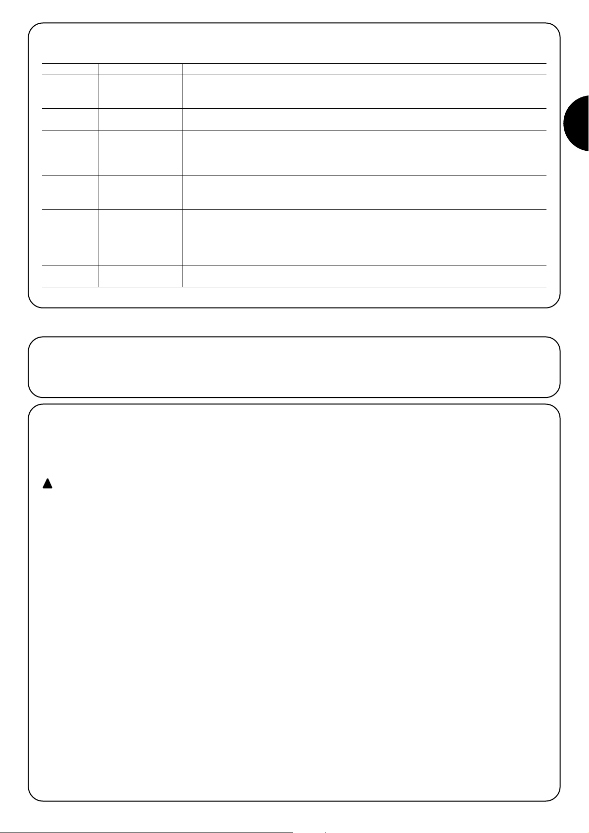
41
I
Prima di iniziare la fase di verifica ed avviamento dell’automazione è
consigliabile sganciare il carrello e porre il portone a metà corsa in
modo che sia libero di muovere sia in apertura che in chiusura.
4) Verifiche finali ed avviamento
4.1) Allacciamento dell’alimentazione
Per l’alimentazione elettrica a SPIN è sufficiente inserire la sua spina
in una presa di corrente. Eventualmente utilizzare un adattatore
comunemente reperibile in commercio se la spina di SPIN non corrisponde alla presa disponibile.
Non tagliare ne rimuovere il cavo in dotazione a SPIN.
Se non è disponibile la presa; l’allacciamento dell’alimentazione a SPIN deve essere eseguito da personale esperto, qualificato, in possesso dei requisiti richiesti e nel pieno rispetto di leggi, norme e regolamenti.
La linea elettrica di alimentazione deve essere protetta
contro il corto circuito e le dispersioni a terra; deve essere presente un dispositivo che permetta di staccare l'alimentazione durante l'installazione o la manutenzione di
SPIN (la stessa spina più presa può andar bene).
Non appena viene fornita tensione a SPIN è consigliabile fare alcune
semplici verifiche:
1. Verificare che il led OK lampeggi regolarmente alla frequenza di
un lampeggio al secondo.
2. Verificare che il motore non comandi il movimento del portone e
che la luce di cortesia sia spenta.
Se tutto questo non avviene occorre spegnere immediatamente l’alimentazione alla centrale e controllare con maggiore attenzione i collegamenti elettrici.
Altre informazioni utili per la ricerca e la diagnosi dei guasti sono presenti nel paragrafo “7.6 Risoluzione dei problemi”
!
3.5) Descrizione dei collegamenti elettrici
In questo paragrafo c’è una breve descrizione dei collegamenti elettrici; ulteriori informazioni nel paragrafo “7.3 Aggiunta o rimozione dispositivi”.
Morsetti Funzione Descrizione
1 – 2 Antenna ingresso di collegamento dell’antenna per ricevitore radio. L’antenna è incorporata su LUCY B, in
alternativa è possibile utilizzare un’antenna esterna oppure lasciare lo spezzone di cavetto,
che funziona da antenna, già presente nel morsetto.
3 – 4 Passo - passo ingresso per dispositivi che comandano il movimento; è possibile collegare contatti di tipo
“Normalmente Aperto”.
5 – 6 Stop ingresso per dispositivi che bloccano o eventualmente arrestano la manovra in corso; con
opportuni accorgimenti sull’ ingresso è possibile collegare contatti tipo “Normalmente Chiuso”,
tipo “Normalmente Aperto” oppure un dispositivo a resistenza costante.
Altre informazioni su STOP sono presenti nel paragrafo “7.3.1 Ingresso STOP”.
3 - 7 Foto ingresso per dispositivi di sicurezza come le fotocellule. Intervengono durante la chiusura
invertendo la manovra. È possibile collegare contatti tipo “Normalmente Chiuso”.
Altre informazioni su FOTO sono presenti nel paragrafo “7.3.2 Ingresso FOTO”.
6 – 8 Fototest ogni volta che viene avviata una manovra vengono controllati tutti i dispositivi di sicurezza e solo se
il test da esito positivo la manovra ha inizio.
Ciò è possibile impiegando un particolare tipo di collegamenti; i trasmettitori delle fotocellule “TX”
sono alimentati separatamente rispetto ai ricevitori “RX”. Altre informazioni sul collegamento sono
presenti nel paragrafo “7.3.2 Ingresso FOTO”.
9 – 10 Lampeggiante su questa uscita è possibile collegare un lampeggiante NICE “LUCY B” con una lampadina a 12V
21W tipo auto. Durante la manovra lampeggia con periodo 0.5s acceso e 0.5s spento.
Page 42
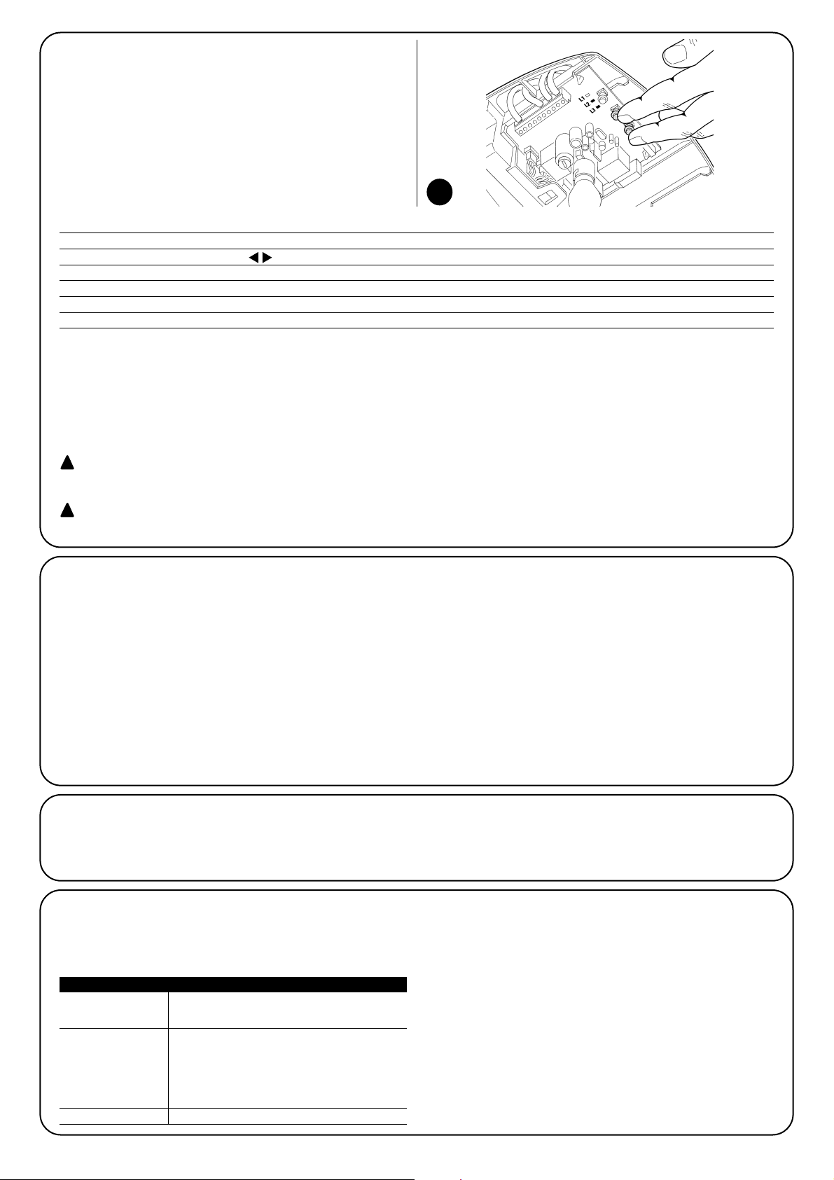
42
4.2) Apprendimento delle posizioni di apertura e
chiusura del portone
È necessario far riconoscere alla centrale le posizioni di apertura e
chiusura del portone; in questa fase viene rilevata la corsa del portone dal fermo meccanico di arresto di chiusura a quello di apertura. Oltre alle posizioni, in questa fase viene rilevata e memorizzata la
configurazione dell’ingresso STOP e la presenza o meno del collegamento in modalità “Fototest” dell’ingresso FOTO.
1. Verificare che la cinghia di trascinamento sia tesa e che i due fermi meccanici siano ben bloccati
2. Agganciare il carrello
3. Premere e tenere premuti i tasti []e [ Set ]
4. Rilasciare i tasti quando inizia la manovra (dopo circa 3s)
5. Attendere che la centrale esegua la fase di apprendimento: chiusura, apertura e richiusura del portone
6. Premere il tasto [PP] per eseguire una manovra completa di apertura
7. Premere il tasto [PP] per eseguire la chiusura
Durante queste manovre la centrale memorizza la forza necessaria nei movimenti di apertura e chiusura.
Se al termine dell’apprendimento i LED L2 e L3 lampeggiano significa che c’è un errore; vedere il paragrafo “7.6 Risoluzioni dei problemi”.
E’ importante che queste prime manovre non vengano interrotte, es. da un comando di STOP.
Se ciò dovesse avvenire occorre eseguire nuovamente l’apprendimento dal punto 1.
La fase di apprendimento delle posizioni e della configurazione degli ingressi STOP e FOTO può essere rifatta in qualsiasi momento anche
dopo l’installazione (ad esempio se viene spostato uno dei fermi meccanici); basta ripeterla dal punto 1.
Durante la ricerca delle posizioni, se la cinghia non è adeguatamente tesa, può verificarsi uno slittamento tra cinghia e pignone. Se ciò si verifica interrompere l’apprendimento premendo il tasto [Stop]; tendere la cinghia avvitando il
dado M8 (D) come in figura 11; quindi ripetere l’apprendimento dal punto 1.
L’apprendimento delle posizioni di apertura e chiusura del portone può essere fatta solo dopo che è trascorso il tempo di memorizzazione e cancellazione dei trasmettitori radio (vedi paragrafo “4.5 Ricevitore radio”)
!
!
34
4.3) Verifica del movimento del portone
Dopo l’apprendimento delle posizioni di apertura e chiusura è consigliabile effettuare alcune manovre per verificare il corretto movimento del portone.
1. Premere il tasto [PP] per comandare una manovra di “Apre”;
verificare che l’apertura del portone avvenga regolarmente senza
variazioni di velocità; solo quando il portone è tra 30 e 20cm dal
fermo meccanico di apertura dovrà rallentare e fermarsi, a 2÷3cm
dal fermo.
2. Premere il tasto [PP] per comandare una manovra di “Chiude”;
verificare che la chiusura del portone avvenga regolarmente senza variazioni di velocità; solo quando il portone è tra 30 e 20cm
dal fermo meccanico di chiusura dovrà rallentare e fermarsi
contro il fermo meccanico di chiusura. Poi viene eseguita una
breve manovra di apertura per scaricare la tensione della cinghia.
3. Durante le manovre verificare che il lampeggiante (se presente)
effettui i lampeggi con periodi di 0,5s acceso e 0,5s spento.
4. Effettuare varie manovre di apertura e chiusura con lo scopo di
evidenziare eventuali difetti di montaggio e regolazione o altre
anomalie come ad esempio punti con maggior attrito.
5. Verificare che il fissaggio del motoriduttore, della guida e dei fermi meccanici siano solidi, stabili ed adeguatamente resistenti
anche durante le brusche accelerazioni o decelerazioni del movimento del portone.
4.4) Funzioni preimpostate
La centrale di controllo di SPIN dispone di alcune funzioni programmabili, di fabbrica queste funzioni vengono regolate in una configurazione
che dovrebbe soddisfare la maggior parte delle automazioni; comunque
le funzioni possono essere cambiate in qualsiasi momento attraverso
una opportuna procedura di programmazione, a questo scopo vedere
paragrafo “7.2 Programmazioni”.
4.5) Ricevitore radio
Per il comando a distanza di SPIN, sulla centrale di controllo, è incorporata una ricevente radio che opera alla frequenza di 433.92 MHz
compatibile con le seguenti tipologie di trasmettitori:
Poiché il tipo di codifica è diverso, il primo trasmettitore inserito
determina anche la tipologia di quelli che si potranno inserire in
seguito. Possono essere memorizzati fino a 160 trasmettitori.
La memorizzazione e la cancellazione dei trasmettitori deve
essere fatta entro i primi 10 secondi dopo aver dato alimentazione. In questo intervallo di tempo il tasto sulla centrale
[RADIO] è dedicato alla memorizzazione e cancellazione
radio. Trascorsi 10 secondi dall'ultimo lampeggio del led L1 o
dall'ultima pressione, il tasto viene disabilitato ed il led L1 viene dedicato alle programmazioni. Per segnalare la fine dell'intervallo di tempo dedicato alla memorizzazione e cancellazione radio viene eseguito 1 lampeggio con la luce di cortesia.
FLO FLO1 – FLO2 – FLO4
VERY VE
FLOR FLOR1 – FLOR2 – FLOR4
VERY VR
ERGO1 – ERGO4 – ERGO6
PLANO1 – PLANO4 – PLANO6
Trasmettitori linea OPERA
SMILO SM2 – SM4
Tabella 6: trasmettitori
Page 43

43
I
1 Comando “PP”
2 Comando “Apertura parziale”
3 Comando “Apre”
4 Comando “Chiude”
Tabella 8: comandi disponibili in Modo II
4.5.1) Memorizzazione dei trasmettitori
Ogni radio trasmettitore viene riconosciuto dal ricevitore radio mediante un “codice” diverso da ogni altro trasmettitore. E’ necessaria quindi
una fase di “memorizzazione” attraverso la quale si predispone il ricevitore a riconoscere ogni singolo trasmettitore, la memorizzazione dei
trasmettitori può avvenire in 2 modalità:
Modo I: in questa modalità la funzione dei tasti del trasmettitore è
fissa e ad ogni tasto corrisponde nella centrale al comando riportato in tabella 7; si esegue una unica fase per ogni trasmettitore del
quale vengono memorizzati tutti i tasti, durante questa fase non ha
importanza quale tasto viene premuto e viene occupato un solo
posto in memoria. In modo I, normalmente un trasmettitore può
comandare una sola automazione
Modo II: in questa modalità ogni singolo tasto del trasmettitore può
essere associato ad uno dei 4 possibili comandi della centrale riportati in tabella 8; per ogni fase viene memorizzato solo un tasto e cioè
quello premuto durante la fase di memorizzazione. Nella memoria
viene occupato un posto per ogni tasto memorizzato.
In modo II i diversi tasti dello stesso trasmettitore possono essere
usati per dare più comandi alla stessa automazione oppure per
comandare più automazioni. Ad esempio, in tabella 9, viene comandata solo l’automazione “A” ed i tasti T3 e T4 sono associati allo
stesso comando; oppure nell’esempio in tabella 10 dove vengono
comandate 3 automazioni “A” (tasti T1 e T2), “B” (tasto T3) e “C”
(tasto T4).
Poiché le procedure di memorizzazione hanno un tempo limite di 10s è necessario leggere prima le istruzioni
riportate nei prossimi paragrafi e poi procedere con l’esecuzione delle stesse.
!
Tasto T1 Comando “PP”
Tasto T2 Comando “Apertura parziale”
Tasto T3 Comando “Apre”
Tasto T4 Comando “Chiude”
Tabella 7: memorizzazione Modo I
Tasto T1 Comando “Apre” Automazione A
Tasto T2 Comando “Chiude” Automazione A
Tasto T3 Comando “Apertura parziale” Automazione A
Tasto T4 Comando “Apertura parziale” Automazione A
Tabella 9: 1° esempio di memorizzazione in Modo II
Tasto T1 Comando “Apre” Automazione A
Tasto T2 Comando “Chiude” Automazione A
Tasto T3 Comando “PP” Automazione B
Tasto T4 Comando “PP” Automazione C
Tabella 10: 2° esempio di memorizzazione in Modo II
Nota: i trasmettitori monocanale dispongono solo del tasto T1, i trasmettitori bicanale dispongono solo dei tasti T1 e T2.
1. Premere e tener premuto il tasto radio sulla centrale (per circa 4s)
4s
2. Rilasciare il tasto quando si accende il led radio sulla centrale
3. Entro10s premere per almeno 3s un tasto qualsiasi del trasmettitore da memorizzare
3s
4. Se la memorizzazione è andata a buon fine il led radio sulla centrale farà 3 lampeggi.
x3
Se ci sono altri trasmettitori da memorizzare, ripetere il punto 3 entro 10s.
La fase di memorizzazione termina se per 10 secondi non vengono ricevuti nuovi codici.
Tabella 11: per memorizzare un trasmettitore in modo I Esempio
4.5.2) Memorizzazione modo I
35
1. Premere il tasto radio sulla centrale un numero di volte pari al comando desiderato secondo la tabella 8
1....4
2. Verificare che il led radio sulla centrale emetta un numero di lampeggi uguali al comando desiderato
1....4
3. Entro10s premere per almeno 3s il tasto desiderato del trasmettitore da memorizzare
3s
4. Se la memorizzazione è andata a buon fine il led sul ricevitore farà 3 lampeggi.
x3
Se ci sono altri trasmettitori da memorizzare per lo stesso comando, ripetere il punto 3 entro 10s.
La fase di memorizzazione termina se per 10 secondi non vengono ricevuti nuovi codici.
Tabella 12: per memorizzare il tasto di un trasmettitore in modo II Esempio
4.5.3) Memorizzazione modo II
Page 44
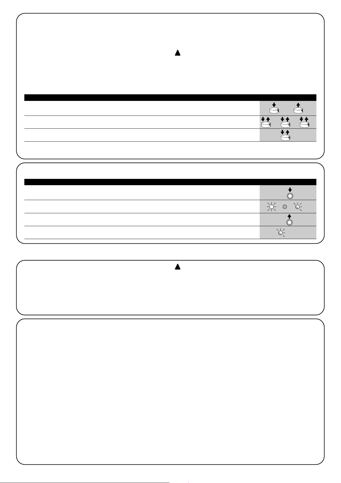
44
1. Premere per almeno 5s il tasto sul nuovo trasmettitore radio, poi rilasciare.
5s
2. Premere lentamente per 3 volte il tasto sul trasmettitore radio già memorizzato.
1s 1s 1s
3. Premere lentamente per 1 volta il tasto sul nuovo trasmettitore radio.
1s
Ora il nuovo trasmettitore radio verrà riconosciuto dal ricevitore e prenderà le caratteristiche che aveva quello già memorizzato.
Se ci sono altri trasmettitori da memorizzare, ripetere tutti i passi per ogni nuovo trasmettitore.
Tabella 13: per memorizzare un trasmettitore “a distanza” Esempio
4.5.4) Memorizzazione “a distanza”
E’ possibile memorizzare un nuovo trasmettitore senza dover agire
direttamente sul tastino del ricevitore; per fare ciò è necessario
disporre di un telecomando già memorizzato e funzionante. Il nuovo
trasmettitore “erediterà” le caratteristiche di quello già memorizzato;
quindi se il primo trasmettitore è memorizzato in modo I anche il nuovo sarà memorizzato in modo I e si potrà premere uno qualunque dei
tasti dei trasmettitori. Se invece il trasmettitore già funzionante è
memorizzato in modo II anche il nuovo sarà memorizzato in modo II
e diventa importante premere, nel primo trasmettitore il tasto relativo
al comando desiderato, e nel secondo trasmettitore il tasto da associare a quel comando.
La memorizzazione a distanza può avvenire in tutti i
ricevitori che si trovano nel raggio della portata del trasmettitore; è quindi necessario tenere alimentato solo
quello interessato all’operazione.
!
Con i due trasmettitori porsi nel raggio di azione dell’automazione ed eseguire i seguenti passi:
1. Premere e tenere premuto il tasto radio sulla centrale
2.
Aspettare che il led radio si accenda, poi aspettare che si spenga, quindi aspettare che emetta 3 lampeggi
x3
3. Rilasciare il tasto radio esattamente durante il 3° lampeggio
4. Se la procedura è andata a buon fine, dopo qualche istante, il led emetterà 5 lampeggi.
x5
Tabella 14: per cancellare tutti i trasmettitori Esempio
4.5.5) Cancellazione dei trasmettitori radio
Questa è la fase più importante nella realizzazione dell’automazione
al fine di garantire la massima sicurezza.
Il collaudo può essere usato anche come verifica periodica dei
dispositivi che compongono l’automatismo.
Il collaudo dell’intero impianto deve essere eseguito da
personale esperto e qualificato che deve farsi carico delle prove richieste, in funzione del rischio presente e di
verificare il rispetto di quanto previsto da leggi, normative
e regolamenti, ed in particolare tutti i requisiti della norma EN12445 che stabilisce i metodi di prova per la verifica degli automatismi per cancelli e porte.
!
5) Collaudo e messa in servizio
5.1) Collaudo
Ogni singolo componente dell’automatismo, ad esempio bordi sensibili, fotocellule, arresto di emergenza, ecc. richiede una specifica
fase di collaudo; per questi dispositivi si dovranno eseguire le procedure riportate nei rispettivi manuali istruzioni.
Per il collaudo di SPIN eseguire la seguente sequenza di operazioni:
1. Verificare che si sia rispettato rigorosamente quanto previsto nel
capitolo 1 “AVVERTENZE”.
2. Sbloccare il portone tirando il cordino di sblocco verso il basso.
Verificare che sia possibile muovere manualmente il portone in
apertura e in chiusura con una forza non superiore a 225N.
3. Riagganciare il carrello.
4. Utilizzando il selettore o il trasmettitore radio, effettuare delle prove di chiusura e apertura del portone e verificare che il movimento corrisponda a quanto previsto.
5. Conviene eseguire diverse prove al fine di valutare la scorrevolezza del portone ed eventuali difetti di montaggio o regolazione
nonché la presenza di particolari punti d’attrito.
6. Verificare uno ad uno il corretto funzionamento di tutti i dispositivi di sicurezza presenti nell’impianto (fotocellule, bordi sensibili
ecc.). In particolare, ogni volta che un dispositivo interviene il led
OK sulla centrale esegue 2 lampeggi più veloci a conferma che la
centrale riconosce l’evento.
7. Per verificare il funzionamento delle fotocellule ed in particolare
che non vi siano interferenze con altri dispositivi, passare un cilindro di diametro 5cm e lunghezza 30cm sull’asse ottico prima vicino al TX, poi vicino all’RX e infine al centro tra i due e verificare
che in tutti i casi il dispositivo intervenga passando dallo stato di
attivo a quello di allarme e viceversa; infine che provochi nella
centrale l’azione prevista; esempio: nella manovra di chiusura
provoca l’inversione di movimento.
8. Se le situazioni pericolose provocate dal movimento del portone
sono state salvaguardate mediante la limitazione della forza d’impatto si deve eseguire la misura della forza secondo quanto previsto dalla norma EN 12445. Se la regolazione della “Velocità” ed
il controllo della “Forza Motore” vengono usati come ausilio al
sistema per la riduzione della forza d’impatto, provare e trovare le
regolazione che offrono i migliori risultati.
Page 45

45
I
5.2) Messa in servizio
La messa in servizio può avvenire solo dopo aver eseguito con esito positivo tutte le fasi di collaudo. Non è consentita la messa in servizio parziale o in situazioni “provvisorie”.
1. Realizzare e conservare per almeno 10 anni il fascicolo tecnico
dell’automazione che dovrà comprendere almeno: disegno complessivo dell’automazione, schema dei collegamenti elettrici, analisi dei rischi e relative soluzioni adottate, dichiarazione di conformità del fabbricante di tutti i dispositivi utilizzati (per SPIN utilizzare la Dichiarazione CE di conformità allegata); copia del manuale
di istruzioni per l’uso e del piano di manutenzione dell’automazione.
2. Fissare in maniera permanente sul portone un’etichetta o targa
con indicate le operazioni per lo sblocco e la manovra manuale
(utilizzare le figure contenute in “Istruzioni ed avvertenze destinate all’utilizzatore del motoriduttore SPIN”).
3. Fissare in maniera permanente sul portone una etichetta o targa
con questa immagine (altezza minima 60mm).
4. Apporre sul portone una targhetta contenente almeno i seguenti
dati: tipo di automazione, nome e indirizzo del costruttore
(responsabile della “messa in servizio”), numero di matricola,
anno di costruzione e marchio “CE”.
5. Compilare e consegnare al proprietario dell’automazione la dichiarazione di conformità dell’automazione.
6. Realizzare e consegnare al proprietario il manuale di “Istruzioni ed
avvertenze per l’uso dell’automazione”.
7. Realizzare e consegnare al proprietario dell’automazione il piano
di manutenzione (che raccoglie le prescrizioni sulla manutenzione
di tutti i dispositivi dell’automazione).
Prima di mettere in servizio l’automatismo informare adeguatamente ed in forma scritta il proprietario (ad esempio sul manuale
di istruzioni ed avvertenze per l’uso dell’automazione) sui pericoli
ed i rischi ancora presenti.
36
In questo capitolo sono riportate le informazioni per la realizzazione del piano di manutenzione e lo smaltimento di SPIN.
6) Manutenzione e smaltimento
6.1) Manutenzione
Per mantenere costante il livello di sicurezza e per garantire la massima durata dell’intera automazione è necessaria una manutenzione
regolare.
La manutenzione deve essere effettuata nel pieno
rispetto delle prescrizioni sulla sicurezza del presente
manuale e secondo quanto previsto dalle leggi e normative vigenti.
Per gli altri dispositivi diversi da SPIN seguire quanto previsto nei
rispettivi piani manutenzione.
1. Per SPIN è necessaria una manutenzione programmata al mas-
simo entro 6 mesi o 3000 manovre dalla precedente manutenzione.
2. Scollegare qualsiasi sorgente di alimentazione elettrica.
3. Verificare lo stato di deterioramento di tutti i materiali che compongono l’automazione con particolare attenzione a fenomeni di
erosione o di ossidazione delle parti strutturali; sostituire le parti
che non forniscono sufficienti garanzie.
4. Verificare lo stato di usura delle parti in movimento: cinghia, carrello, pignoni e tutte le parti del portone, sostituire le parti usurate.
Ricollegare le sorgenti di alimentazione elettrica ed eseguire tutte
le prove e le verifiche previste nel paragrafo “5.1 Collaudo”.
!
6.2) Smaltimento
SPIN è costituito da diverse tipologie di materiali, alcuni di questi
possono essere riciclati; acciaio, alluminio, plastica, cavi elettrici; altri
dovranno essere smaltiti: batterie e schede elettroniche.
Alcuni componenti elettronici potrebbero contenere
sostanze inquinanti, non disperderli nell’ambiente. Informatevi sui sistemi di riciclaggio o smaltimento attenendovi alle norme in vigore a livello locale.
1. Scollegare l’alimentazione elettrica dall’automatismo.
2. Smontare tutti i dispositivi ed accessori, seguendo il procedimento inverso a quello descritto nel capitolo “3 Installazione”
3. Separare per quanto possibile le parti che possono o devono
essere riciclate o smaltite in modo diverso, ad esempio le parti
metalliche da quelle plastiche, le schede elettroniche ecc.
4. Smistare ed affidare i vari materiali così separati ai centri abilitati
al recupero ed allo smaltimento previsti a livello locale.
!
Page 46

46
In questo capitolo verranno trattate le possibilità di programmazione, personalizzazione, diagnostica e ricerca guasti su SPIN
7) Approfondimenti
RADIO Entro i primi 10 secondi dall’accensione esegue la funzione “RADIO” permet-
tendo di memorizzare e cancellare i trasmettitori radio da utilizzare con SPIN.
Dopo questo intervallo di tempo il tasto non è più utilizzato.
Stop Il tasto “STOP” permette di fermare la manovra; se premuto per più di 3
SET secondi permette di entrare in programmazione, nelle modalità descritte di
seguito.
PP Il tasto “PP” permette di comandare l’apertura e la chiusura del portone;
oppure di spostare verso l’alto o il basso il punto di programmazione.
7.1) Tasti di programmazione
Sulla centrale di controllo di SPIN sono presenti 3 tasti che possono essere usati sia
per il comando della centrale durante le prove sia per le programmazioni:
7.2) Programmazioni
Sulla centrale di controllo di SPIN sono disponibili alcune funzioni
programmabili; la regolazione delle funzioni avviene attraverso 2 tasti
presenti sulla centrale: []e [Set] e vengono visualizzate attra-
verso 3 led: L1, L2, L3.
Le programmazioni si dividono in 2 gruppi:
Programmazione all’accensione: questo tipo di programmazione può essere fatta solo subito dopo aver dato alimentazione a
SPIN. Tenendo premuto il tasto [Set] durante l’accensione della
centrale si attiva questo tipo di programmazione.
Programmazione standard: questo tipo di programmazione può
essere fatta in qualsiasi momento e viene attivata tenendo premuto
il tasto [Set].
Per entrambe le programmazioni le funzioni programmabili disponibili sono disposte su 2 livelli:
Primo livello: funzioni regolabili in modo ON-OFF (attivo oppure
non attivo); in questo caso i led L1, L2, L3 indica una funzione, se
acceso la funzione è attiva, se spento la funzione non è attiva; vedere tabelle 15 e 15a.
Secondo livello: parametri regolabili su una scala di valori (valori
da 1 a 3); in questo caso ogni led L1, L2, L3 indica il valore regolato tra i 3 possibili; vedere tabella 17 e 17a.
N° Descrizione Esempio
L1 Sensibilità variabile Questa funzione permette di attivare o disattivare la sensibilità con la quale vengono rilevati gli ostacoli.
Di fabbrica la sensibilità di questo sistema è variabile (led L1 spento): maggiore sensibilità dove il motore
ha poco sforzo, minore sensibilità dove il motore ha più sforzo. Il tutto con lo scopo di rilevare gli
ostacoli con la massima precisione. È possibile disattivare la sensibilità variabile e rimangono i 3 livelli
“fissi” di forza motore (led L1 acceso).
L2 Fototest / Elettroserratura Questa funzione permette di abilitare l’uscita 8 della morsettiera per il funzionamento con Fototest o con
Elettroserratura. Di fabbrica l’uscita 8 è attiva per la funzione “Fototest” (led L2 spento). In alternativa nella
centrale di SPIN è possibile programmare l’uscita per il comando di una elettroserratura (led L2 acceso).
L3 Apertura parziale Questa funzione permette di scegliere la quota di Apertura parziale corta o lunga. Di fabbrica l’apertura
parziale è impostata lunga (circa 1m, led L3 acceso). In alternativa è possibile programmare l’Apertura
parziale corta (circa 15cm, led L3 spento).
Al termine della procedura di “Programmazione all’accensione” i led L1, L2 e L3 visualizzano lo stato delle funzioni della “Programmazione
standard”.
Tabella 15: elenco funzioni programmabili della “Programmazione all’accensione”
7.2.1) Funzioni primo livello (funzioni ON-OFF)
N° Descrizione Esempio
L1 Velocità chiusura Questa funzione permette di scegliere la velocità del motore durante la manovra di chiusura tra 2 livelli:
“veloce”, “lenta”. Di fabbrica la velocità impostata è “veloce” (led L1 acceso). In alternativa,
disattivando la funzione, la velocità impostata è “lenta” (led L1 spento).
L2 Velocità apertura Questa funzione permette di scegliere la velocità del motore durante la manovra di apertura tra 2 livelli:
“veloce”, “lenta”. Di fabbrica la velocità impostata è “veloce” (led L2 acceso). In alternativa,
disattivando la funzione, la velocità impostata è “lenta” (led L2 spento).
L3 Chiusura Automatica Questa funzione permette una chiusura automatica del portone dopo il tempo pausa programmato, di
fabbrica il Tempo Pausa è posto a 30 secondi ma può essere modificato a 15 o 60 secondi. Di fabbrica il
funzionamento è “semiautomatico” perché la Chiusura automatica è disattivata (led L3 spento)
Durante il funzionamento normale di SPIN i led L1, L2 e L3 sono accesi o spenti in base allo stato della funzione che rappresentano appartenente alla “Programmazione standard”, ad esempio L3 è acceso se è attiva la “Chiusura automatica”. L1 visualizza anche lo stato della funzione “radio” nei primi 10” dall’accensione.
Tabella 15a: elenco funzioni programmabili della “Programmazione standard”
37
Page 47

47
I
7.2.2) Programmazione primo livello (funzioni ON-OFF)
Di fabbrica le funzioni del primo livello sono impostate come descritto in tabelle 15 e 15a, ma si possono cambiare in qualsiasi momento
come indicato in tabelle 16 e 16a. Fare attenzione nell’eseguire la procedura perché c’è un tempo massimo di 10s tra la pressione di un tasto
e l’altro, allo scadere del quale la procedura finisce automaticamente memorizzando le modifiche fatte fino a quel momento.
1. Spegnere SPIN (ad esempio togliendo il fusibile F1)
2. Premere e tenere premuto il tasto [Set]
3. Accendere SPIN (ad esempio inserendo il fusibile F1)
4. Attendere il lampeggio di avvio della centrale quindi mantenere premuto il tasto [Set]
finché inizia a lampeggiare L1 (circa 6s) L1 6s
5. Rilasciare il tasto [Set] quando il led L1 inizia a lampeggiare
L1
6. Premere il tasto []per spostare il led lampeggiante sul led che rappresenta la funzione da
modificare
7. Premere il tasto [Set] per cambiare lo stato della funzione
(lampeggio breve = OFF; lampeggio lungo = ON)
8. Attendere 10s per uscire dalla programmazione per fine tempo massimo.
10s
Nota: i punti 6 e 7 possono essere ripetuti durante le stessa fase di programmazione per porre ON o OFF altre funzioni
Tabella 16: per cambiare le funzioni ON-OFF della “Programmazione all’accensione” Esempio
SET
SET
SET
SET
1. Premere e tener premuto il tasto [Set] per circa 3s
3s
2. Rilasciare il tasto [Set] quando il led L1 inizia a lampeggiare
L1
3. Premere il tasto []per spostare il led lampeggiante sul led che rappresenta la funzione da
modificare
4. Premere il tasto [Set] per cambiare lo stato della funzione
(lampeggio breve = OFF; lampeggio lungo = ON)
5. Attendere 10s per uscire dalla programmazione per fine tempo massimo.
10s
Nota: i punti 3 e 4 possono essere ripetuti durante le stessa fase di programmazione per porre ON o OFF altre funzioni
Tabella 16a: per cambiare le funzioni ON-OFF della “Programmazione all’accensione” Esempio
SET
SET
SET
Page 48

48
Sensibilità
variabile
Recupero
cinghia
Rallentamento
chiusura
Alta
Media
Bassa
Nessun recupero
Recupero minimo
Recupero massimo
Corto
Medio
Lungo
7.2.3) Funzioni secondo livello (parametri regolabili)
Tabella 17: elenco funzioni programmabili secondo livello della “Programmazione all’accensione”
Led di entrata Parametro Led (livello) valore Descrizione
Quando la sensibilità variabile è attivata è possibile regolarla su
3 soglie di intervento. La sensibilità variabile Alta è adatta a
portoni di piccole dimensioni correttamente bilanciati
Regola la misura del recupero cinghia. Dopo la chiusura completa del portone viene avviata una brevissima manovra di
apertura regolabile con questo parametro.
Regola la lunghezza del rallentamento durante la manovra di
chiusura.
Nota: “ ” rappresenta la regolazione di fabbrica
L1
L2
L3
L1
L2
L3
L1
L2
L3
L1
L2
L3
7.2.4) Programmazione secondo livello (parametri regolabili)
Di fabbrica i parametri regolabili sono posti come evidenziato in tabelle 17 e 17a con: “ ” ma si possono cambiare in qualsiasi momento
come indicato in tabelle 18 e 18a. Fare attenzione nell’eseguire la procedura perché c’è un tempo massimo di 10s tra la pressione di un tasto
e l’altro, allo scadere del quale la procedura finisce automaticamente memorizzando le modifiche fatte fino a quel momento.
1. Spegnere SPIN (ad esempio togliendo il fusibile F1)
2. Premere e tenere premuto il tasto [Set]
3. Accendere SPIN (ad esempio inserendo il fusibile F1)
4. Attendere il lampeggio di avvio della centrale quindi mantenere premuto il tasto [Set]
finché inizia a lampeggiare L1 (circa 6s) L1 6s
5. Rilasciare il tasto [Set] quando il led L1 inizia a lampeggiare
L1
6. Premere il tasto []per spostare il led lampeggiante sul “led di entrata” che rappresenta il
parametro da modificare
7. Premere e mantenere premuto il tasto [Set]; il tasto [Set] va mantenuto premuto durante tutti i passi
5 e 6
8. Attendere circa 3s dopodichè si accenderà il led che rappresenta il livello attuale del parametro da
modificare 3s
9. Premere il tasto []per spostare il led che rappresenta il valore del parametro.
10. Rilasciare il tasto [Set]
11. Attendere 10s per uscire dalla programmazione per fine tempo massimo.
10s
Nota: i punti da 6 a 10 possono essere ripetuti durante le stessa fase di programmazione per regolare più parametri
Tabella 18: per cambiare i parametri regolabili della “Programmazione all’accensione” Esempio
SET
SET
SET
SET
Forza motore
Funzione PP
Tempo Pausa
Bassa
Media
Alta
Apre - stop - chiude- apre
Apre - stop - chiude- stop
Condominiale
15 secondi
30 secondi
60 secondi
Tabella 17a: elenco funzioni programmabili secondo livello della “Programmazione standard”
Led di entrata Parametro Led (livello) valore Descrizione
Regola la forza massima che il motore può sviluppare
per muovere il portone.
Regola la sequenza di comandi associati all’ingresso
P.P oppure al 1° comando radio (vedere tabelle 7 e 8).
Regola il tempo di pausa cioè il tempo prima della
richiusura automatica. Ha effetto solo se la chiusura
automatica è attiva
Nota: “ ” rappresenta la regolazione di fabbrica
Tutti i parametri possono essere regolati a piacere senza nessuna controindicazione; solo la regolazione della “Forza motore” potrebbe richiedere una attenzione particolare:
• E’ sconsigliato utilizzare valori alti di forza per compensare il fatto che l’anta abbia dei punti di attrito anomali; una forza eccessiva può pre-
giudicare il funzionamento del sistema di sicurezza o danneggiare l’anta.
• Se il controllo della “forza motore” viene usato come ausilio al sistema per la riduzione della forza di impatto, dopo ogni regolazione ripe-
tere la misura della forza, come previsto dalla norma EN 12445.
• L’usura e le condizioni atmosferiche influiscono sul movimento del portone, periodicamente e necessario ricontrollare la regolazione della
forza.
L1
L2
L3
L1
L2
L3
L1
L2
L3
L1
L2
L3
SET
Page 49

49
I
1. Premere e tener premuto il tasto [Set] per circa 3s
3s
2. Rilasciare il tasto [Set] quando il led L1 inizia a lampeggiare
L1
3. Premere il tasto []per spostare il led lampeggiante sul “led di entrata” che rappresenta
il parametro da modificare
4. Premere e mantenere premuto il tasto [Set]; il tasto [Set] va mantenuto premuto
durante tutti i passi 5 e 6
5. Attendere circa 3s dopodichè si accenderà il led che rappresenta il livello attuale del parametro
da modificare
6. Premere il tasto []per spostare il led che rappresenta il valore del parametro
7. Rilasciare il tasto [Set]
8. Attendere 10s per uscire dalla programmazione per fine tempo massimo.
10s
Nota: i punti da 3 a 7 possono essere ripetuti durante le stessa fase di programmazione per regolare più parametri
Tabella 18a: per cambiare i parametri regolabili della “Programmazione standard” Esempio
SET
SET
SET
SET
7.2.5) Esempio di programmazione primo livello (funzioni ON-OFF)
Come esempio viene riportata la sequenza di operazioni per cambiare l’impostazione di fabbrica delle funzioni per disattivare la funzione
“Sensibilità Variabile” (L1) e attivare “Apertura Parziale Corta” (L3).
1. Spegnere SPIN (ad esempio togliendo il fusibile F1)
2. Premere e tenere premuto il tasto [Set]
L1
3. Accendere SPIN (ad esempio inserendo il fusibile F1)
4. Attendere il lampeggio di avvio della centrale quindi mantenere premuto il tasto [Set] finché inizia a
lampeggiare L1 (circa 6s) L1 6s
5. Rilasciare il tasto [Set]
6. Premere una volta il tasto [Set] per cambiare lo stato della funzione associala ad L1 (Sensibilità Variabile)
ora il led L1 lampeggia con lampeggio lungo L1
7. Premere 2 volte il tasto []per spostare il led lampeggiante sul led L3
L3
8. Premere 1 volta il tasto [Set] per cambiare lo stato della funzione associala ad L3 (Apertura Parziale)
ora il led L3 lampeggia con lampeggio lungo L3
9. Attendere 10s per uscire dalla programmazione per fine tempo massimo
10s
Durante l’attesa per uscire dalla programmazione i led L1 ed L3 devono rimanere accesi ad indicare che sono attive le funzioni di “Sensibilità
Variabile Disattivata” e “Apertura Parziale Corta”.
Tabella 19: esempio di programmazione primo livello della “Programmazione all’accensione” Esempio
SET
SET
SET
Come esempio viene riportata la sequenza di operazioni per cambiare l’impostazione di fabbrica delle funzioni per attivare le funzioni di “Velocità apertura alta” (L2) e “Chiusura Automatica” (L3).
1. Premere e tener premuto il tasto [Set] per circa 3s
3s
2. Rilasciare il tasto [Set] quando il led L1 inizia a lampeggiare
L1
3. Premere 1 volta il tasto []per spostare il led lampeggiante sul led L2
L2
4. Premere una volta il tasto [Set] per cambiare lo stato della funzione associala ad L2 (Velocità apertura)
ora il led L2 lampeggia con lampeggio lungo L2
5. Premere 1 volta il tasto []per spostare il led lampeggiante sul led L3
L3
6. Premere 1 volta il tasto [Set] per cambiare lo stato della funzione associala ad L3 (Chiusura Automatica)
ora il led L3 lampeggia con lampeggio lungo L3
7. Attendere 10s per uscire dalla programmazione per fine tempo massimo
10s
Al termine di queste operazioni i led L2 ed L3 devono rimanere accesi ad indicare che sono attive le funzioni di “Velocità apertura Alta” e “Chiusura Automatica”.
Tabella 19a: esempio di programmazione primo livello della “Programmazione standard” Esempio
SET
SET
SET
SET
SET
SET
Page 50

50
7.2.6) Esempio di programmazione secondo livello (parametri regolabili)
Come esempio viene riportata la sequenza di operazioni per cambiare l’impostazione di fabbrica dei parametri e regolare il “Recupero cinghia” in nessun recupero (entrata su L2 e livello su L1) e selezionare il “Rallentamento Chiusura” lungo (entrata su L3 e livello su L3).
1. Spegnere SPIN (ad esempio togliendo il fusibile F1)
2. Premere e tenere premuto il tasto [Set]
3. Accendere SPIN (ad esempio inserendo il fusibile F1)
4. Attendere il lampeggio di avvio della centrale quindi mantenere premuto il tasto [Set] finché inizia
a lampeggiare L1 (circa 6s) L1 6s
5. Rilasciare il tasto [Set]
6. Premere 1 volta il tasto [] per spostare il led lampeggiante su L2
L2
7. Premere e mantenere premuto il tasto [Set]; il tasto [Set] va mantenuto premuto durante tutti i
passi 8 e 9
8. Attendere circa 3s fino a che si accenderà il led L2 che rappresenta il livello attuale della
“Recupero cinghia” L2 3s
9. Premere 2 volte il tasto []per spostare il led acceso su L1 che elimina il “Recupero cinghia”
L1
10. Rilasciare il tasto [Set]
11. Premere 1 volta il tasto []per spostare il led lampeggiante sul led L3
L3
12. Premere e mantenere premuto il tasto [Set]; il tasto [Set] va mantenuto premuto durante
tutti i passi 13 e 14
13. Attendere circa 3s fino a che si accenderà il led L2 che rappresenta il livello attuale del
“Rallentamento Chiusura”. L2 3s
14. Premere 1 volta il tasto []per spostare il led acceso su L3 che rappresenta il nuovo valore del
“Rallentamento Chiusura”. L3
15. Rilasciare il tasto [Set]
16. Attendere 10s per uscire dalla programmazione per fine tempo massimo.
10s
Tabella 20: esempio di programmazione secondo livello Esempio
SET
SET
SET
SET
SET
SET
SET
Come esempio viene riportata la sequenza di operazioni per cambiare l’impostazione di fabbrica dei parametri e regolare la “Forza Motore”
in alta (entrata su L1 e livello su L3) e aumentare il “Tempo Pausa” a 60s (entrata su L3 e livello su L3).
1. Premere e tener premuto il tasto [Set] per circa 3s
3s
2. Rilasciare il tasto [Set] quando il led L1 inizia a lampeggiare
L1
3. Premere e mantenere premuto il tasto [Set]; il tasto [Set] va mantenuto premuto durante tutti i
passi 4 e 5
4. Attendere circa 3s fino a che si accenderà il led L2 che rappresenta il livello attuale della “Forza Motore”
L2 3s
5. Premere 1 volta il tasto []per spostare il led acceso su L3 che rappresenta il nuovo valore della
“Forza Motore” L3
6. Rilasciare il tasto [Set]
7. Premere 2 volte il tasto []per spostare il led lampeggiante sul led L3
L3
8. Premere e mantenere premuto il tasto [Set]; il tasto [Set] va mantenuto premuto durante
tutti i passi 9 e 10
9. Attendere circa 3s fino a che si accenderà il led L2 che rappresenta il livello attuale del “Tempo Pausa”.
L2 3s
10. Premere 1 volta il tasto []per spostare il led acceso su L3 che rappresenta il nuovo valore del
“Tempo Pausa”. L3
11. Rilasciare il tasto [Set]
12. Attendere 10s per uscire dalla programmazione per fine tempo massimo.
10s
Tabella 20a: esempio di programmazione secondo livello della “Programmazione standard” Esempio
SET
SET
SET
SET
SET
SET
Page 51

51
I
7.3) Aggiunta o rimozione dispositivi
Ad una automazione con SPIN è possibile aggiungere o rimuovere
dispositivi in qualsiasi momento. In particolare agli ingressi di STOP
e FOTO possono essere collegati vari tipi di dispositivi come indicato nei paragrafi “7.3.1 Ingresso STOP”e 7.3.2 Fotocellule. In figura è
riportato lo schema elettrico per il collegamento dei vari dispositivi.
7.3.1) Ingresso STOP
STOP è l’ingresso che provoca l’arresto immediato della manovra
seguito da una breve inversione. A questo ingresso possono essere
collegati dispositivi con uscita a contatto normalmente aperto “NA”,
normalmente chiuso “NC” oppure dispositivi con uscita a resistenza
costante 8,2KΩ, ad esempio bordi sensibili.
La centrale riconosce il tipo di dispositivo collegato all’ingresso
STOP durante la fase di apprendimento (vedere paragrafo “4.2
Apprendimento delle posizioni di apertura e chiusura del portone”);
successivamente viene provocato uno STOP quando si verifica una
qualsiasi variazione rispetto allo stato appreso.
Con opportuni accorgimenti è possibile collegare all’ingresso STOP
più di un dispositivo, anche di tipo diverso:
• Più dispositivi NA si possono collegare in parallelo tra di loro sen-
za alcun limite di quantità.
• Più dispositivi NC si possono collegare in serie tra di loro senza
alcun limite di quantità.
• Più dispositivi a resistenza costante 8,2KΩ possono essere colle-
gati “in cascata” con una sola resistenza di terminazione da 8,2KΩ
• E’ possibile la combinazione di NA ed NC ponendo i 2 contatti in
parallelo con l’avvertenza di porre in serie al contatto NC una resistenza da 8,2KΩ (ciò rende possibile anche la combinazione di 3
dispositivi: NA, NC e 8,2KΩ).
Se l’ingresso STOP è usato per collegare dispositivi con
funzioni di sicurezza solo i dispositivi con uscita a resistenza costante 8,2 KΩ garantiscono la categoria 3 di
sicurezza ai guasti secondo la norma EN 954-1.
!
Page 52

52
7.3.2) Fotocellule
La centrale di SPIN è provvista della funzione “Fototest” che aumenta l’affidabilità dei dispositivi di sicurezza, permettendo di raggiungere la
“categoria 2” secondo la norma EN 954-1 per quanto riguarda l’insieme centrale e fotocellule di sicurezza.
Ogni volta che viene avviata una manovra vengono controllati i dispositivi di sicurezza coinvolti, solo se tutto è a posto la manovra ha inizio.
Se invece il test non da esito positivo (fotocellula accecata dal sole, cavi in corto circuito ecc.) viene individuato il guasto e la manovra non
viene eseguita.
Per la funzione “fototest” è necessario uno specifico collegamento dei trasmettitori delle fotocellule (vedere fig.40 e 41). La centrale riconosce il collegamento in modo “fototest”durante la fase di apprendimento (vedere paragrafo “4.2 apprendimento delle posizioni di apertura e
chiusura del portone”)
• Collegamento senza funzione “Fototest” (Figura 38 e 39)
Alimentare trasmettitori e ricevitori direttamente dall’uscita servizi della centrale (morsetti 3 - 6).
• Collegamento con funzione “Fototest” (Figura 40, e 41):
L’alimentazione dei ricevitori è presa direttamente dall’uscita dei servizi (morsetti 3 - 6), mentre quella dei trasmettitori dall’uscita “Fototest”
(morsetti 8 - 6). La corrente massima utilizzabile sull’uscita “Fototest” è di 100mA.
Nel caso si usino 2 coppie di fotocellule che si possono interferire tra loro, attivare il sincronismo come descritto nelle istruzioni delle fotocellule.
38 39
40 41
7.3.3) Elettroserratura
Di fabbrica l’uscita “fototest” è attiva per la funzione “Fototest”.
In alternativa nella centrale di SPIN è possibile programmare l’uscita
per il comando di una elettroserratura. All’avvio di ogni manovra di
apertura l’uscita viene attivata per una durata di 2 secondi; in questo modo è possibile collegare un dispositivo elettroserratura. Nella
manovra di chiusura l’uscita non viene attivata per cui l’elettroserratura deve essere capace di riarmarsi meccanicamente.
L’uscita non può comandare direttamente l’elettroserratura ma solo
un carico da 24Vac - 2W. L’uscita dovrà essere interfacciata con un
relé, come illustrato in figura.
Page 53

53
I
7.4.1) Funzione “Apri Sempre”
La funzione “Apri Sempre” è una proprietà della centrale di controllo
che permette di comandare sempre una manovra di apertura quando il comando di “Passo-Passo” ha una durata superiore a 3 secondi; ciò è utile ad esempio per collegare all’ingresso PP il contatto di
un orologio programmatore per mantenere aperto il portone per una
certa fascia oraria.
Questa proprietà è valida qualunque sia la programmazione dell’ingresso di PP (vedere parametro “Funzione PP” in tabella 17).
7.4) Funzioni particolari
7.4.2) Funzione “Muovi comunque”
Nel caso in cui qualche dispositivo di sicurezza non dovesse funzionare correttamente o fosse fuori uso, è possibile comunque comandare e muovere il portone in modalità “Uomo presente”.
Per i dettagli vedere il paragrafo “Comando con sicurezze fuori uso”
presente nell’allegato “Istruzioni ed avvertenze destinate all’utilizzatore del motoriduttore SPIN”.
7.5) Collegamento altri dispositivi
Se vi fosse l’esigenza di alimentare dispositivi esterni ad esempio un
lettore di prossimità per tessere a transponder oppure la luce d’illuminazione del selettore a chiave è possibile prelevare l’alimentazione
come indicato in figura 42. La tensione di alimentazione è 24Vac 30% ÷ +50% con corrente massima disponibile di 100mA.
24Vac
42
7.6) Risoluzione dei problemi
Nella tabella seguente è possibile trovare utili indicazioni per affrontare casi di malfunzionamento in cui è possibile incorrere durante l’installazione o a causa di un guasto.
43
Tabella 21: ricerca guasti
Sintomi Probabile causa e possibile rimedio
Il trasmettitore radio non comanda il portone
ed il led sul trasmettitore non si accende
Il trasmettitore radio non comanda il portone
ma il led sul trasmettitore si accende.
Non si comanda nessuna manovra ed il led
OK non lampeggia
Non si comanda nessuna manovra ed il
lampeggiante è spento
La manovra non parte e la luce di cortesia fa
alcuni lampeggi
La manovra ha inizio ma subito dopo avviene la breve inversione
Verificare se le pile del trasmettitore sono scariche, eventualmente sostituirle.
Verificare se il trasmettitore è correttamente memorizzato nel ricevitore radio.
Verificare la corretta emissione del segnale radio del trasmettitore con questa prova empirica: premere un tasto ed appoggiare il led all’antenna di un comune apparecchio radio
(meglio se di tipo economico) acceso e sintonizzato sulla banda FM alla frequenza di
108,5Mhz o quanto più prossima; si dovrebbe ascoltare un leggero rumore con pulsazione
gracchiante.
Verificare che SPIN sia alimentato con la tensione di rete 230V. Verificare che i fusibili F1 e
F2 non siano interrotti; in questo caso, verificare la causa del guasto e poi sostituirli con
altri dello stesso valore di corrente e caratteristiche.
Verificare che il comando venga effettivamente ricevuto. Se il comando giunge sull’ingresso
PP il led OK esegue un doppio lampeggio per segnalare che il comando è stato ricevuto.
Contare il numero di lampeggi e verificare secondo quanto riportato in tabella 22.
La forza selezionata potrebbe essere troppo bassa per muovere il portone. Verificare se ci
sono degli ostacoli ed eventualmente selezionare una forza superiore.
F2
F1
Page 54

54
Led OK Causa AZIONE
Led STOP Causa AZIONE
Spento
7.7.2) Segnalazioni sulla centrale
Nella centrale di SPIN ci sono una serie di led ognuno dei quali può
dare delle segnalazioni particolari, sia nel funzionamento normale
che in caso di anomalia.
Tabella 23: led sui morsetti della centrale
Anomalia
Verificare se c’è alimentazione; verificare che i fusibili non siano intervenuti; nel
caso, verificare la causa del guasto e poi sostituirli con altri dello stesso valore.
Acceso Anomalia grave
C’è una anomalia grave; provare a spegnere per qualche secondo la centrale;
se lo stato permane c’è un guasto e occorre sostituire la scheda elettronica.
Un lampeggio al secondo Tutto OK Funzionamento normale della centrale
2 lampeggi veloci
E’ avvenuta una variazione
dello stato degli ingressi
E’ normale quando avviene un cambiamento di uno degli ingressi: PP,
STOP, intervento delle fotocellule o viene utilizzato il trasmettitore radio.
Serie di lampeggi separati da
una pausa di un secondo
Varie
E’ la stessa segnalazione che c’è sul lampeggiante o luce di cortesia.
Vedere Tabella 22
Spento
Intervento dell’ingresso di
STOP
Verificare i dispositivi collegati all’ingresso di STOP
Acceso Tutto OK Ingresso STOP attivo
44
7 lampeggi
pausa di 1 secondo
7 lampeggi
All’inizio della manovra una o più fotocellule non danno il consenso al movimento, verificare se ci sono ostacoli.
Durante il movimento di chiusura è normale se effettivamente è presente un
ostacolo.
7.7.1) Segnalazione con lampeggiante e luce di cortesia
Se viene collegato un lampeggiante, durante la manovra esegue un lampeggio ogni secondo; quando accadono delle anomalie, vengono
emessi dei lampeggi più brevi; i lampeggi si ripetono due volte, separati da una pausa di un secondo. Le stesse segnalazioni di diagnostica
sono riportate dalla luce di cortesia.
Tabella 22: segnalazioni sul lampeggiante FLASH
Lampeggi veloci Causa AZIONE
2 lampeggi
pausa di 1 secondo
2 lampeggi
Intervento di una fotocellula
3 lampeggi
pausa di 1 secondo
3 lampeggi
Intervento del limitatore della
“Forza Motore”
Durante il movimento il portone ha incontrato un maggiore attrito; verificare la
causa.
4 lampeggi
pausa di 1 secondo
4 lampeggi
Intervento dell’ingresso di
STOP
All’inizio della manovra o durante il movimento c’è stato un intervento dell’ingresso di STOP; verificare la causa.
5 lampeggi
pausa di 1 secondo
5 lampeggi
Errore nei parametri interni
della centrale elettronica
Attendere almeno 30 secondi e riprovare a dare un comando; se lo stato rimane potrebbe esserci un guasto grave ed occorre sostituire la scheda elettronica.
6 lampeggi
pausa di 1 secondo
6 lampeggi
Superato il limite massimo di
manovre per ora.
Attendere alcuni minuti che il limitatore di manovre ritorni sotto il limite massimo.
Errore nei circuiti elettrici
interni
Scollegare tutti i circuiti di alimentazione per qualche secondo poi riprovare a
dare un comando; se lo stato rimane potrebbe esserci un guasto grave sulla
scheda oppure sul cablaggio del motore. Fare le verifiche e le eventuali sostituzioni.
7.7) Diagnostica e segnalazioni
Alcuni dispositivi offrono direttamente delle segnalazioni particolari attraverso le quali è possibile riconoscere lo stato di funzionamento o dell’eventuale malfunzionamento.
Page 55

55
I
Led 1 Descrizione
• Programmazione delle funzioni in corso
• Se lampeggia assieme ad L2 indica che è necessario eseguire la fase di apprendimento delle posizioni di apertura e chiusura del portone (vedere paragrafo “4.2 Apprendimento delle posizioni di apertura e chiusura del portone”).
Led L3 Descrizione
Led L2 Descrizione
Spento
Tabella 24: led sui tasti della centrale
Durante il funzionamento normale è corretto.
Durante il funzionamento normale indica che è stato ricevuto un codice radio che non è tra quelli in memoria.
• Programmazione delle funzioni in corso
• Memorizzazione o cancellazione dei trasmettitori radio.
Acceso
Lampeggia
Spento Durante il funzionamento normale indica “Velocità motore” lenta.
Durante il funzionamento normale indica “Velocità motore” veloce.
• Programmazione delle funzioni in corso
• Se lampeggia assieme ad L3 indica che è necessario eseguire la fase di apprendimento posizioni di apertura e
chiusura del portone (vedere paragrafo “4.2 Apprendimento delle posizioni di apertura e chiusura del portone”).
Acceso
Lampeggia
Spento Durante il funzionamento normale indica “Chiusura automatica” non attiva.
Durante il funzionamento normale indica “Chiusura automatica” attiva.Acceso
Lampeggia
7.8) Accessori
Per SPIN sono presenti i seguenti accessori opzionali. Consultare il
catalogo prodotti di Nice S.p.A. per l’elenco completo ed aggiornato degli accessori.
Per tutti
• SPA2 Sblocco meccanico con cordino metallico. Da impiegare
negli impianti che prevedono come punto d’accesso il solo portone da automatizzare.
Per tutti
• SPA5 Braccio oscillante. È necessario quando il portone da auto-
matizzare è di tipo basculante, sia a contrappesi che a molle.
Page 56

56
Alimentazione di emergenza No
Uscita lampeggiante per 1 lampeggiante LUCYB (12V, 21W)
Luce di cortesia SPIN
Luce di cortesia SPIN/V1
12V-21W attacco BA15
12V-21W attacco BA15
Utilizzo in atmosfera particolarmente acida
o salina o potenzialmente esplosiva
225 x 330 h 100 / 3,3Kg
Con lo scopo di migliorare i propri prodotti, Nice S.p.a si riserva il diritto di modificare le caratteristiche tecniche in qualsiasi momento e senza preavviso pur mantenendo funzionalità e destinazione d’uso.
Tutte le caratteristiche tecniche riportate si riferiscono alla temperatura ambientale di 20°C (±5°C).
8) Caratteristiche tecniche
Tipologia
Caratteristiche tecniche: SPIN
Motoriduttore elettromeccanico per il movimento automatico di portoni da garage ad uso
residenziale completo di centrale elettronica di controllo
Pignone Diametro 9.5mm, 28 denti; per guide SNA11 e guide in dotazione a SPIN10KCE
Modello SN6011
Coppia massima allo spunto
[corrispondente alla capacità di sviluppare
una forza per mettere in movimento l’anta]
9.9Nm
[550N]
4.95Nm
[275N]
Coppia nominale [corrispondente alla capacità di sviluppare una forza per mantenere in
movimento l’anta]
Velocità a vuoto [corrispondenti
se programmata velocità “Veloce”]
103 rpm
[0,14m/s]
La centrale consente di programmare 2 velocità pari a 100% - 60% circa
Velocità alla coppia nominale
[corrispondenti se programmata velocità
“Veloce”]
52 rpm
[0,07m/s]
Frequenza massima cicli di funzionamento 30 cicli / giorno (la centrale limita i cicli al massimo previsto nelle tabelle 3 e 4)
Tempo massimo funzionamento continuo 3 minuti (la centrale limita il funzionamento continuo al massimo previsto nelle tabelle 3 e 4)
Limiti d’impiego
Generalmente SPIN è in grado di automatizzare portoni sezionali o basculanti che rientrano
nelle dimensioni riportati in tabella 2 e secondo i limiti previsti nelle tabelle 3 e 4
Potenza massima assorbita 200W
Classe di isolamento 1 (è necessaria la messa a terra di sicurezza)
Ingresso STOP
Per contatti normalmente chiusi, normalmente aperti oppure a resistenza costante
8,2KΩ; in autoapprendimento (una variazione rispetto allo stato memorizzato provoca il
comando “STOP”).
Ingresso PP Per contatti normalmente aperti (la chiusura del contatto provoca il comando PP)
Ingresso ANTENNA Radio 52Ω per cavo tipo RG58 o simili
Ricevitore radio Incorporato
Alimentazione SPIN
Alimentazione SPIN/V1
230Vac (±10%) 50/60Hz.
120Vac (±10%) 50/60Hz.
Funzioni programmabili 6 funzioni di tipo ON-OFF e 6 funzioni regolabili (vedere tabelle 15, 15a, 17 e 17a)
Temperatura di funzionamento -20°C ÷ 50°C
No
Grado di protezione IP 40 utilizzo solo in ambienti interni o protetti
Dimensioni e peso
Funzioni in autoapprendimento
Autoapprendimento del tipo di dispositivo di "STOP" (contatto NA, NC o resistenza 8,2KΩ)
Autoapprendimento delle posizioni di apertura e chiusura del portone e calcolo dei punti di
rallentamento ed apertura parziale.
Modello tipo Guida contenuta in SPIN10KCE SNA11
Tipologia profilo da 3 pezzi in acciaio zincato profilo unico in acciaio zincato
Lunghezza guida 3.15m 3.15m
Altezza guida 35mm 35mm
Corsa utile 2.6m 2.6m
Lunghezza cinghia 6m 6m
Altezza cinghia 6mm 6mm
Resistenza alla trazione 730N 730N
Caratteristiche tecniche guide
Page 57

57
I
Caratteristiche tecniche ricevitore radio incorporato
Tipologia Ricevitore a 4 canali per radiocomando incorporato
Frequenza 433.92MHz
Codifica Digitale codice fisso a 12 Bit, tipo FLO
Digitale Rolling code a 52 Bit, tipo FLOR
Digitale Rolling code a 64 Bit, tipo SMILO
Compatibilità trasmettitori (1) FLO, VERY VE
FLOR, VERY VR; solo gruppo singolo: ERGO, PLANO, PLANOTIME
SMILO
Trasmettitori memorizzabili Fino a 160 se memorizzati in Modo I
Impedenza di ingresso 52Ω
Sensibilità migliore di 0.5µV
Portata dei trasmettitori Da 100 a 150m, questa distanza può variare in presenza di ostacoli e disturbi elettromagnetici
eventualmente presenti ed è influenzata dalla posizione dell'antenna ricevente
Uscite /
Temperatura di funzionamento -20°C ÷ 55°C
Nota 1: il primo trasmettitore inserito determina anche la tipologia di quelli che si potranno inserire in seguito
Tipologia Trasmettitore 2 canali per radiocomando
Frequenza 433.92MHz
Codifica Digitale codice fisso a 12 Bit Digitale Rolling code a 52 Bit, Digitale Rolling code a 64 Bit,
tipo FLO tipo FLOR tipo SMILO
Tasti 2
Alimentazione 12Vdc con batteria tipo 23A
Assorbimento 25mA
Durata della batteria 1 anno, stimata su una base di 20 comandi/giorno della durata di 1s a 20°C
(alle basse temperature l’efficienza della batteria diminuisce)
Potenza irradiata 100µW
Dimensioni e peso 72 x 40 h 18mm / 30g 72 x 40 h 18mm / 30g Diametro 48 h14mm / 19g
Grado di protezione IP 40 (utilizzo in casa o ambienti protetti)
Temperatura di funzionamento -40°C ÷ 85°C
Caratteristiche tecniche trasmettitore: FLO2 trasmettitore: FLO2R-S trasmettitore: SM2
Page 58

Page 59

59
I
Complimenti per aver scelto per la vostra automazione
un prodotto Nice! Nice S.p.a. produce componenti per
l'automazione di cancelli, porte,serrande, tapparelle e tende da sole: motoriduttori, centrali di comando,radiocomandi, lampeggianti, fotocellule e accessori. Nice utilizza
solo materiali e lavorazioni di qualità, e per vocazione ricerca soluzioni innovative che semplifichino al massimo l'utilizzo delle sue apparecchiature, curate nelle soluzioni tecniche, estetiche, ergonomiche: nella grande gamma Nice
il vostro installatore avrà senz'altro scelto il prodotto più
adatto alle vostre esigenze. Nice non è però il produttore
della vostra automazione, che è invece il risultato di un'opera di analisi, valutazione, scelta dei materiali, e realizzazione dell'impianto eseguita dal vostro installatore di fiducia. Ogni automazione è unica e solo il vostro installatore
possiede l'esperienza e la professionalità necessarie ad
eseguire un impianto secondo le vostre esigenze, sicuro
ed affidabile nel tempo, e soprattutto a regola d'arte,
rispondente cioè alle normative in vigore. Un impianto di
automazione è una bella comodità, oltre che un valido
sistema di sicurezza e, con poche, semplici attenzioni, è
destinato a durare negli anni. Anche se l'automazione in
vostro possesso soddisfa il livello di sicurezza richiesto
dalle normative, questo non esclude l'esistenza di un
“rischio residuo”, cioè la possibilità che si possano generare situazioni di pericolo, solitamente dovute ad un utilizzo incosciente o addirittura errato, per questo motivo
desideriamo darvi alcuni consigli sui comportamenti da
seguire per evitare ogni inconveniente:
• Prima di usare per la prima volta l’automazio-
ne, fatevi spiegare dall'installatore l'origine dei rischi
residui, e dedicate qualche minuto alla lettura del
manuale di istruzioni ed avvertenze per l'utiliz-
zatore consegnatovi dall'installatore. Conservate il
manuale per ogni dubbio futuro e consegnatelo ad un
eventuale nuovo proprietario dell'automazione.
• Le fotocellule non sono un dispositivo di sicu-
rezza ma soltanto un dispositivo ausiliario alla
sicurezza. Sono costruite con tecnologia ad altissima
affidabilità ma possono, in situazioni estreme, subire
malfunzionamenti o addirittura guastarsi ed in certi casi
il guasto potrebbe non essere subito evidente.
Per questi motivi, e comunque per buona regola:
- Il transito è consentito solo se il cancello o portone è
completamente aperto e con ante ferme.
- E' ASSOLUTAMENTE VIETATO transitare mentre il can-
cello o portone si sta chiudendo!
Verificare periodicamente il corretto funzionamento delle fotocellule e far eseguire i controlli di manutenzione
previsti, almeno ogni 6 mesi.
• La vostra automazione è un macchinario che
esegue fedelmente i vostri comandi; un uso incosciente ed improprio può farlo diventare pericoloso: non
comandate il movimento dell'automazione se nel suo
raggio di azione si trovano persone, animali o cose.
• Bambini: un impianto di automazione garantisce un
alto grado di sicurezza, impedendo con i suoi sistemi di
rilevazione il movimento in presenza di persone o cose,
e garantendo un'attivazione sempre prevedibile e sicura. È comunque prudente vietare ai bambini di giocare
in prossimità dell'automazione e per evitare attivazioni
involontarie non lasciare i telecomandi alla loro portata:
non è un gioco!
• Controllare spesso l'impianto, in particolare i cavi,
le molle e i supporti per scoprire eventuali sbilanciamenti e segni di usura o danni.
Verificare mensilmente che il motore di movimentazione
si inverta quando la porta tocca un oggetto alto 50 mm
posto al suolo. Non usare l'automazione, se è necessaria una riparazione o regolazione, dal momento che
un guasto all'installazione o una porta non correttamente bilanciata può provocare ferite.
• Anomalie: Non appena notate qualunque comportamento anomalo da parte dell'automazione, togliete alimentazione elettrica all'impianto ed eseguite lo sblocco
manuale. Non tentate da soli alcuna riparazione, ma
richiedete l'intervento del vostro installatore di fiducia:
nel frattempo l'impianto può funzionare come un'apertura non automatizzata, una volta sbloccato il moto
riduttore come descritto più avanti.
• Manutenzione: Come ogni macchinario la vostra
automazione ha bisogno di una manutenzione periodica affinché possa funzionare più a lungo possibile ed in
completa sicurezza. Concordate con il vostro installatore un piano di manutenzione con frequenza periodica;
Nice consiglia un intervento ogni 6 mesi per un normale utilizzo domestico, ma questo periodo può variare in
funzione dell'intensità d'uso. Qualunque intervento di
controllo, manutenzione o riparazione deve essere eseguito solo da personale qualificato.
• Anche se ritenete di saperlo fare, non modificate l'impianto ed i parametri di programmazione e di regolazione dell'automazione: la responsabilità è del vostro
installatore.
• Il collaudo, le manutenzioni periodiche e le eventuali
riparazioni devono essere documentate da chi le esegue e i documenti conservati dal proprietario dell'impianto.
Gli unici interventi che vi sono possibili e vi consigliamo di effettuare periodicamente sono la pulizia dei
vetrini delle fotocellule e la rimozione di eventuali foglie
o sassi che potrebbero ostacolare l'automatismo. Per
impedire che qualcuno possa azionare il portone, prima
di procedere, ricordatevi di sbloccare l'automati-
smo (come descritto più avanti), scollegare tutte le
sorgenti di alimentazione (anche le batterie tampo-
ne se presenti) e di utilizzare per la pulizia solamente un
panno leggermente inumidito con acqua.
• Smaltimento: Al termine della vita dell'automazione,
assicuratevi che lo smantellamento sia eseguito da personale qualificato e che i materiali vengano riciclati o
smaltiti secondo le norme valide a livello locale.
• In caso di rotture o assenza di alimentazione:
Attendendo l'intervento del vostro installatore, o il ritorno dell'energia elettrica, l'automazione può essere azionata come una qualunque apertura non automatizzata.
Per fare ciò è necessario eseguire lo sblocco manuale:
tale operazione è stata particolarmente studiata da Nice
per assicurarvi sempre la massima facilità di utilizzo,
senza uso di attrezzi particolari o necessità di sforzo fisico.
Istruzioni ed avvertenze destinate all’utilizzatore del motoriduttore SPIN
Istruzioni importanti di sicurezza
Per la sicurezza delle persone è importante seguire queste istruzioni
Conservare queste istruzioni
Queste istruzioni possono integrare le “Istruzioni ed avvertenze per l’uso dell’automazione” che l’installatore deve consegnare al proprietario dell’automazione e comunque devono essere integrate da esse.
!
Page 60

60
Sblocco e movimento manuale: prima di eseguire questa operazione porre attenzione che lo sblocco può avveni-
re solo quando il portone è fermo.
1. Tirare il cordino di sblocco verso il basso fino a sentire lo sgancio del carrello.
2. A questo punto è possibile agire manualmente sul portone
3. Per ripristinare la funzionalità dell’automatismo riportare il portone nella posizione iniziale fino a sentire l’aggancio
del carrello.
Comando con sicurezze fuori uso: nel caso i dispositivi di sicurezza presenti nel portone non dovessero funzionare correttamente è possibile comunque comandare il
portone.
• Azionare il comando del portone (col telecomando, col
selettore a chiave, ecc.); se tutto è a posto il portone si
aprirà o chiuderà normalmente, altrimenti il lampeggiante farà alcuni lampeggi e la manovra non partirà (il
numero di lampeggi dipende dal motivo per cui la
manovra non può partire).
• In questo caso, entro tre secondi si deve azionare
nuovamente e tenere azionato il comando.
• Dopo circa 2s inizierà il movimento del portone in
modalità a “uomo presente”, cioè finché si mantiene il
comando, il portone continuerà a muoversi; appena il
comando viene rilasciato, il portone si ferma.
Con le sicurezze fuori uso è necessario far riparare quanto prima l’automatismo.
Sostituzione pila del telecomando: se il vostro radio-
comando dopo qualche tempo vi sembra funzionare peggio, oppure non funzionare affatto, potrebbe semplicemente dipendere dall’esaurimento della pila (a seconda
dell’uso, possono trascorrere da diversi mesi fino ad oltre
un anno). Ve ne potete accorgere dal fatto che la spia di
conferma della trasmissione non si accende, è fioca,
oppure si accende solo per un breve istante. Prima di
rivolgervi all’installatore provate a scambiare la pila con
quella di un altro trasmettitore eventualmente funzionante:
se questa fosse la causa dell’anomalia, sarà sufficiente
sostituire la pila con altra dello stesso tipo.
Attenzione: Le pile contengono sostanze inquinanti: non
gettarle nei rifiuti comuni ma utilizzare i metodi previsti dai
regolamenti locali.
1. Aprire il coperchio bianco premendo e facendolo
ruotare.
2. Togliere la lampadina premendo verso l’alto e poi
facendola ruotare. Inserire una nuova lampadina da
12V / 21W attacco BA15.
Sostituzione lampada: prima di eseguire questa operazione togliere alimentazione allo SPIN.
Siete soddisfatti? Nel caso voleste aggiungere nella vostra casa un nuovo impianto di automazione, rivolgendovi
allo stesso installatore e a Nice vi garantirete, oltre che la consulenza di uno specialista e i prodotti più evoluti del mercato, il migliore funzionamento e la massima compatibilità delle automazioni.
Vi ringraziamo per aver letto queste raccomandazioni, e vi auguriamo la massima soddisfazione dal vostro nuovo
impianto: per ogni esigenza presente o futura rivolgetevi con fiducia al vostro installatore.
Page 61

Page 62

62
Spin10KCE
Spin11KCE
Table des matières: page
1 Avertissements 63
2 Description du produit 63
2.1 Limites d’utilisation 64
2.2 Installation typique 65
2.3 Liste des câbles 65
3 Installation 66
3.1 Contrôles préliminaires 66
3.2 Fixation du SPIN 66
3.2.1 Assemblage du rail fourni avec le SPIN10KCE 67
3.2.2 Assemblage du rail SNA11 68
3.2.3 Fixation de l’opérateur au rail 68
3.2.4 Fixation de l’opérateur au plafond 68
3.3 Installation des divers dispositifs 69
3.4 Connexions électriques 70
3.5 Description des connexions électriques 71
4 Vérifications finales et mise en service 71
4.1 Branchement au secteur 71
4.2 Reconnaissance des positions d’ouverture
et de fermeture de la porte 72
4.3 Vérification du mouvement de la porte 72
4.4 Fonctions préprogrammées 72
4.5 Récepteur radio 72
4.5.1 Mémorisation des émetteurs 73
4.5.2 Mémorisation en mode I 73
4.5.3 Mémorisation en mode II 73
4.5.4 Mémorisation à distance 74
4.5.5 Effacement des émetteurs radio 74
5 Essai et mise en service 74
5.1 Essai 74
5.2 Mise en service 75
6 Maintenance et mise au rebut 75
6.1 Maintenance 75
6.2 Mise au rebut 75
7 Approfondissements 76
7.1 Touches de programmation 76
7.2 Programmations 76
7.2.1 Fonctions de premier niveau (fonctions ON-OFF)76
7.2.2 Programmation du premier niveau
(fonctions ON-OFF) 77
7.2.3 Fonctions de deuxième niveau
(paramètres réglables) 78
7.2.4 Programmation du deuxième niveau
(paramètres réglables) 78
7.2.5 Exemple de programmation du premier niveau
(fonctions ON-OFF) 79
7.2.6 Exemple de programmation du deuxième niveau
(paramètres réglables) 80
7.3 Ajout ou retrait de dispositifs 81
7.3.1 Entrée STOP 81
7.3.2 Entrée PHOTO 82
7.3.3 Serrure électrique 82
7.4 Fonctions particulières 83
7.4.1 Fonction « Ouvre toujours » 83
7.4.2 Fonction « Manœuvre dans tous les cas » 83
7.5 Connexion d’autres dispositifs 83
7.6 Résolution des problèmes 83
7.7 Diagnostic et signalisations 84
7.7.1 Signalisation avec clignotant et éclairage
automatique 84
7.7.2 Signalisations sur la logique de commande 84
7.8 Accessoires 85
8 Caractéristiques techniques 86
Instructions et recommandations destinées à l’utilisateur
de l’opérateur SPIN 89
Page 63

63
F
SPIN est une ligne d’opérateurs destinés à l’automatisation de
portes sectionnelles et, avec l’accessoire spécial SPA5 non fourni,
de portes basculantes à ressort ou à contrepoids, débordantes ou
non.
Les SPIN fonctionnent grâce à l’énergie électrique; en cas de coupure de courant, il est possible de débrayer l’opérateur et de
manœuvrer la porte à la main. Les produits décrits dans le tableau 1
font partie de la ligne SPIN.
* pour connaître les types d’émetteurs qui peuvent être utilisés, lire le paragraphe «4.5 Récepteur radio».
1) Recommandations
Consignes importantes de sécurité pour l'installation
Une installation incorrecte peut causer de graves dommages.
Suivre toutes les instructions d’installation
Ce manuel d’instructions contient des informations importantes concernant la sécurité pour l’installation: il faut donc lire toutes les instructions
avant de procéder à l’installation. Conserver soigneusement ce manuel
pour d’éventuelles consultations futures.
Chaque fois que des données, des recommandations et tout ce qui est
commun à tous les produits sont fournis dans ce manuel, on utilisera le
nom de la ligne: «SPIN». La description des différents produits se trouve
au chapitre 2 «Description du produit». Compte tenu des dangers qui
peuvent se vérifier durant l’installation et l’utilisation de SPIN, pour une
sécurité maximale, il faut que l’installation soit effectuée en parfaite
conformité avec les lois, normes et règlements. Dans ce chapitre, nous
donnons des recommandations d’ordre général; d’autres recommandations importantes se trouvent dans les chapitres «3.1 Contrôles préliminaires» et «5 Essai et mise en service».
ATTENTION: d’après la législation européenne la plus
récente, la réalisation d’une porte ou d’un portail automatique présente les caractéristiques prévues par la Directive
98/37/CE (Directive «Machines») et en particulier par les
normes EN 12445, EN 12453 et EN 12635 qui permettent de
déclarer la présomption de conformité.
D’autres informations et les conseils pour l’analyse des risques et la réalisation
du dossier technique sont disponibles sur le site: «www.niceforyou.com».
• Le présent manuel est réservé au personnel technique qualifié pour
l’installation. À l’exception de l’encart «Instructions et recommandations destinées à l’utilisateur de l’opérateur SPIN» que l’installateur
devra détacher, aucune autre information contenue dans la présente
notice ne peut concerner l’utilisateur final!
• Une utilisation de SPIN différente de ce qui est prévu dans cette notice est interdite; les utilisations impropres peuvent être sources de dangers ou de dommages aux personnes et aux choses.
• Avant de commencer l’installation, il faut effectuer l’analyse des
risques comprenant la liste des conditions de sécurité requises par
l’annexe I de la Directive «Machines», en indiquant les solutions adoptées. Nous rappelons que l’analyse des risques est l’un des documents qui constituent le «dossier technique» de l’automatisation.
• Vérifier s’il est nécessaire d’installer d’autres dispositifs pour compléter l’automatisation avec SPIN suivant les conditions spécifiques de
l’application et les risques présents; il faut considérer par exemple les
risques d’impact, d’écrasement, de cisaillement, de coincement, etc.,
et d’autres dangers en général.
• N’effectuer des modifications sur aucune des parties si elles ne sont pas
prévues dans le présent manuel. Des opérations de ce type entraîneraient obligatoirement des problèmes de fonctionnement. NICE décline
toute responsabilité pour les dommages dérivant de produits modifiés.
• Pendant l’installation et l’utilisation, éviter que des parties solides ou
liquides ne pénètrent à l’intérieur de la logique de commande ou
d’autres composants ouverts; s’adresser éventuellement au service
après-vente NICE; l’utilisation de SPIN dans de telles circonstances
peut créer des situations de danger.
• L’automatisme ne peut pas être utilisé avant d’avoir effectué la mise en
service comme l’explique le chapitre: «5 Essai et mise en service».
• Les matériaux d’emballage de SPIN doivent être mis au rebut conformément à la réglementation locale.
• En cas de panne, qui ne peut pas être résolue grâce aux informations
fournies dans ce manuel, contacter le service après-vente NICE.
• En cas d’intervention de disjoncteurs ou de fusibles, avant de les réarmer, il faut identifier et éliminer la panne.
• Avant d’accéder aux bornes situées sous le carter de SPIN, déconnecter tous les circuits d’alimentation; si le dispositif de déconnexion
n’est pas visible, accrocher un panonceau: «ATTENTION MAINTENANCE EN COURS».
!
!
2) Description du produit
1
Modèle type Opérateur Rail Récepteur radio Émetteur radio
SPIN10KCE SN6011 3x1 m Incorporé FLO2R-S*
SPIN11KCE SN6011 3x1 m Incorporé FLO2R-S*
Tableau 1: description de la composition SPIN.
Page 64

64
2.1) Limites d’utilisation
Les données relatives aux performances des produits de la ligne SPIN figurent dans le chapitre «8 Caractéristiques techniques» et sont les
seules valeurs qui permettent d’évaluer correctement si l’opérateur est adapté à l’application.
Les caractéristiques structurales des produits SPIN permettent de les utiliser sur des portes sectionnelles ou basculantes, dans les limites
indiquées dans les tableaux 2, 3 et 4.
Les mesures du tableau 2 sont purement indicatives et servent seulement à une estimation générale. La capacité réelle de SPIN à automatiser une porte particulière dépend du degré d’équilibrage de la porte, des frottements des rails et d’autres phénomènes, même occasionnels, comme la pression du vent ou la présence de glace, qui pourraient gêner le mouvement de la porte.
Pour une vérification réelle, il est absolument indispensable de mesurer la force nécessaire pour déplacer la porte sur toute sa course et de
contrôler que cette dernière ne dépasse pas le «couple nominal» indiqué dans le chapitre 8 «Caractéristiques techniques»; de plus, pour établir le nombre de cycles/heure et de cycles consécutifs, il faut tenir compte des indications des tableaux 3 et 4.
La hauteur de la porte permet de déterminer le nombre maximum de cycles à l’heure et de cycles consécutifs tandis que la force nécessaire pour l’actionner permet de déterminer le pourcentage de réduction des cycles; par exemple, si la porte fait 2,2 m de hauteur, on peut avoir
12 cycles/heure et 6 cycles consécutifs mais s’il faut 250 N pour déplacer la porte, il faut les réduire à 70%, soit 8 cycles/heure et environ 4
cycles consécutifs.
Pour éviter les surchauffes, la logique de commande comprend un limiteur qui se base sur l'effort du moteur et sur la durée des cycles: il
intervient quand la limite maximale est dépassée.
Nota: 1 kg = 9,81 N donc, par exemple, 500 N = 51 kg.
Hauteur porte mètres cycles/heure maximums
cycles consécutifs maximums
Jusqu’à 2 16 8
2÷2,5 12 6
2,5÷3 10 5
3÷3,5 8 4
Tableau 3: limites relatives à la hauteur de la porte.
Force pour actionner la porte N
Pourcentage de réduction des cycles SN6011
Jusqu’à 200 100 %
200÷300 70 %
300÷400 25 %
Tableau 4: limites en fonction de la force nécessaire pour actionner la porte.
Modèle type: Porte SECTIONNELLE
Porte BASCULANTE non débordante
Porte BASCULANTE débordante (avec
(avec accessoire SPA5) accessoire SPA5) ou à ressorts (sans SPA5)
Hauteur Larg. Hauteur Larg. Hauteur Larg.
SPIN10KCE 2.4m 3.7m 2.2m 3.5m 2.8m 3.5m
SPIN11KCE 2.4m 3.7m 2.2m 3.5m 2.8m 3.5m
Tableau 2: limites d’utilisation des opérateurs SPIN.
Page 65

65
F
2.2) Installation typique
La figure 2 présente l’installation typique pour une porte sectionnelle.
2
1 SPIN
2 Photocellules
3 Photocellules sur colonne (fig. 3)
4 Bord primaire
5 Clignotant avec antenne
incorporée
6 Sélecteur à clé
7 Émetteur radio
Les figures 3 et 4 présentent les installations typiques pour une porte basculante débordante et non débordante.
Pour les installations sur les portes basculantes, l’accessoire SPA5 est nécessaire.
!
3 4
5
6
C
B
A
2
2
4
B
B
D
7
1
3
2.3) Liste des câbles
Dans l’installation typique de la figure 3 sont également indiqués les
câbles nécessaires pour les connexions des différents dispositifs; le
tableau 5 indique les caractéristiques des câbles.
Les câbles utilisés doivent être adaptés au type d’installation; par exemple, on conseille un câble type H03VVF pour la pose à l’intérieur.
!
Note 1: les deux câbles de 2x0,5mm2peuvent être remplacés par un seul câble de 4x0,5mm2.
Note 2: pour la connexion des bords sensibles sur les portes, il faut utiliser des dispositifs spéciaux qui permettent la connexion même
quand la porte est en mouvement.
Connexion Type de câble Longueur maximum admise
A: clignotant avec antenne 1 câble 2x0,5mm
2
20m
1 câble blindé type RG58 20 m 20m (longueur conseillée: moins de 5 m)
B: Photocellules 1 câble 2x0,25mm2pour l’émission 30m
1 câble 4x0,25mm2pour la réception 30m
C: Sélecteur à clé 2 câbles 2x0,5mm2(note 1) 50m
D: Bord sensible primaire 1 câble 2x0,5mm2(note 2) 30m
Tableau 5: liste des câbles
B
Page 66

66
3.1) Contrôles préliminaires
Avant de continuer l’installation de SPIN, il faut effectuer les
contrôles suivants:
• Vérifier et s'assurer qu’après l'installation aucune partie de la por-
te n’encombre la rue ou le trottoir.
• Vérifier que tout le matériel à utiliser est en excellent état, adapté à
l’usage et conforme aux normes.
• Vérifier que la structure de la porte est adaptée pour être équipée
d’un automatisme.
• Vérifier que la force et les dimensions de la porte rentrent dans les
limites d’utilisation indiquées au paragraphe 2.1 «Limites d’utilisation».
• Vérifier, en comparant avec les valeurs figurant dans le chapitre “8
Caractéristiques techniques”, que la friction statique (c’est-à-dire
la force nécessaire pour mettre la porte en mouvement) est inférieure à la moitié du «couple maximum» et que la friction dynamique (c’est-à-dire la force nécessaire pour maintenir la porte en
mouvement) est inférieure à la moitié du «couple nominal»; on
conseille une marge de 50 % sur les forces car les conditions climatiques adverses peuvent faire augmenter les frictions.
• Vérifier que dans la course de la porte, aussi bien en fermeture qu’en
ouverture, il n’y a pas de points présentant une plus grande friction.
• Vérifier la robustesse des butées mécaniques et contrôler qu’il n’y
a pas de risque de sortie des rails de la porte.
• Vérifier que la porte est bien équilibrée, c’est-à-dire qu’elle ne doit
pas bouger si elle est laissée dans une position quelconque.
• Vérifier que les points de fixation des différents dispositifs (photo-
cellules, boutons, etc.) se trouvent dans des endroits à l’abri des
chocs et que les surfaces sont suffisamment solides.
• Vérifier qu’il y a les espaces minimums et maximums indiqués sur
les figures 5 et 6.
• Vérifier et veiller à ce que le débrayage manuel se situe à moins de
1,8 m de hauteur.
• Éviter que les parties de l’automatisme puissent être plongées
dans l’eau ou dans d’autres substances liquides.
• Ne pas placer les composants de SPIN à proximité de sources de
chaleur ni les exposer à des flammes; ces actions peuvent endommager le SPIN, causer des problèmes de fonctionnement et provoquer un incendie ou des dangers.
• Si la porte est munie d’un portillon pour le passage de piétons
incorporé, il faut s’assurer que ce portillon ne gêne pas la course
normale et prévoir éventuellement un système d’interverrouillage.
• Si la porte à automatiser est basculante, vérifier sur la figure 7 la
mesure E, à savoir la distance minimum entre le côté supérieur du
rail et le point maximum atteint par le bord supérieur de la porte.
Sinon SPIN ne peut pas être monté.
• Connecter la fiche d’alimentation de SPIN à une prise électrique
avec mise à la terre.
• La prise électrique doit être protégée par un disjoncteur magnéto-
thermique associé à un déclencheur différentiel.
7
3.2) Fixation SPIN
La fixation de SPIN comprend 3 parties:
• Assemblage du rail (voir le paragraphe 3.2.1 pour le rail fourni avec
SPIN10KCE et le paragraphe 3.2.2 pour le rail SNA11).
• Fixation de l’opérateur au rail (voir le paragraphe 3.2.3).
• Fixation de l’opérateur au plafond (voir le paragraphe 3.2.4).
L’installation de SPIN doit être effectuée par du personnel qualifié, dans le respect des lois, des normes et
des règlements ainsi que de toutes les instructions de ce
manuel.
!
3) Installation
5
6
200mm
300mm
380mm
E 65÷300 mm
C 2970mm D 380mm
B 0÷400mm
A 40÷400mm
200mm
Page 67

67
F
B
3.2.1) Assemblage du rail fourni avec SPIN10KCE.
Le rail fourni avec SPIN10KCE doit être assemblé de la façon suivante:
1. En suivant les indications de la figure 8, extraire le renvoi de tension de la courroie (8a); enfiler courroie dans la poulie (8b); réintroduire le
renvoi de tension de la courroie dans le rail (8c).
4. Positionner les deux extrémités de la courroie dans les fentes du chariot inférieur (C), en les occupant complètement. Fixer les extrémi-
tés de la courroie avec les 2 vis V4.2x9.5 et les 2 rondelles R05 fournies, comme sur la figure 11.
5. Avec la vis V6x18 et l’écrou M6 correspondant, fixer l’étrier de traction (D) au chariot supérieur (E), comme sur la figure 12.
6. Accrocher le chariot supérieur (E) au chariot inférieur (C) et porter tout le chariot à l’intérieur du rail, comme sur la figure 13.
7. Assembler les trois pièces à l’intérieur des deux étriers de jonction (F), en utilisant un marteau, comme sur les figures 14 et 15.
Important: les rails doivent coulisser dans les étriers jusqu’à ce qu’on entende un déclic sec.
8. Positionner, avec beaucoup d’attention, la courroie dans le rail en évitant les entortillements.
9. Avec beaucoup de force la tête (B) dans l’extrémité libre du rail, comme sur la figure 16.
10.En agissant enfin sur la vis de réglage (H) du renvoi de tension de la courroie, tendre la courroie comme sur la figure 17
Attention: Une courroie TRÈS risque de casser l’opérateur; une courroie PEU tendue peut causer des bruits gênants.
11 12 13
C
14 15 16 17
H
D
E
E
C
8A 8B 8C
10
A
B
9
A
A
2. Faire passer la même extrémité de la tête (B), comme sur la figure 9.
Note: Faites attention à la position de la courroie: elle doit se trouver avec les dents vers l’intérieur, droite et sans torsions.
3. Orienter la partie inférieure du chariot, en faisant coïncider les rainures avec les deux extrémités de la courroie, comme sur la figure 10.
F
Page 68

68
3.2.2) Assemblage du rail SNA11
Le rail SNA11 est préassemblé. La seule opération à effectuer est de
tendre la courroie au moyen de l’écrou M8 (H), comme indiqué sur
la figure 17, jusqu'à ce qu’elle soit suffisamment rigide.
3.2.3) Fixation de l’opérateur au rail
1. Unir l’opérateur SPIN à la tête du rail (B); puis le fixer au moyen des 4 vis V6.3x38, comme indiqué sur la figure 18.
2. Le moteur peut être tourné dans trois positions différentes, comme indiqué sur la figure 19.
18 19
3.2.4) Fixation de l’opérateur au plafond
1. En respectant les mesures A et B de la figure 5, tracer au centre de la porte les deux points de fixation de la patte avant du rail. En fonc-
tion du type de matériau, la patte avant peut être fixée avec des rivets, des chevilles ou des vis (figures 20 et 21). Si les mesures A et B
(figure 5) le permettent, la patte peut être fixée directement au plafond, comme indiqué sur la figure 22.
2. Après avoir percé sur les points prévus, en laissant l’opérateur au sol, soulever le rail par l’avant et le fixer avec deux vis, chevilles ou rivets
selon la surface.
3. Fixer les pattes (I) avec les vis M6x15 (L) et les écrous M6 (M) en choisissant le trou qui permet de respecter le plus possible la mesure
B, comme indiqué sur la figure 23.
4. En utilisant une échelle, soulever l’opérateur jusqu'à ce que les pattes soient contre le plafond. Tracer les points de perçage puis remettre
l’opérateur au sol, comme indiqué sur la figure 24.
20 21 22
23 24
L
M
I
B
Page 69

69
F
5. Percer sur les points tracés puis, en utilisant une échelle, soulever l’opérateur jusqu'à ce que les pattes se trouvent contre les trous qui
viennent d’être percés et les fixer à l’aide de vis et de chevilles adaptées au matériau, comme indiqué sur la figure 25.
6. Vérifier que le rail est parfaitement horizontal puis couper avec une petite scie la partie excédante des pattes, comme indiqué sur la figu-
re 26.
7. Avec la porte fermée, tirer le cordon pour décrocher le chariot (E), comme indiqué sur la figure 27.
8. Faire coulisser le chariot jusqu'à ce que l’équerre de la porte (D) soit sur le bord supérieur de la porte, exactement perpendiculaire au rail
(G). Fixer l’équerre de la porte (D) avec des rivets ou des vis, comme indiqué sur la figure 28. Utiliser des vis ou des rivets adaptés au
matériau de la porte en vérifiant qu’ils sont en mesure de supporter tout l’effort nécessaire pour l’ouverture et la fermeture de la porte.
9. Desserrer les vis des deux butées mécaniques d’arrêt puis déplacer la butée mécanique d’arrêt avant (O) devant le chariot, comme indi-
qué sur la figure 29. Pousser le chariot avec force dans le sens de la fermeture et, dans la position atteinte, serrer fortement la vis (N).
10.Ouvrir manuellement la porte jusqu’au point d’ouverture voulu, déplacer la butée mécanique d’arrêt arrière (Q) au niveau du chariot, com-
me indiqué sur la figure 30, et la bloquer en serrant fortement la vis (P).
11.Essayer de déplacer manuellement la porte. Vérifier que le chariot coulisse facilement, sans frottement sur le rail et que la manœuvre
manuelle est facile et ne requiert pas d’efforts particuliers.
25 26
27 28
29 30
E
G
D
O
N
Q
P
3.3) Installation des divers dispositifs
Installer les autres dispositifs prévus en suivant les instructions correspondantes. Vérifier dans le paragraphe «3.5 Description des
connexions électriques» et sur la figure 2 les dispositifs qui peuvent
être connectés à SPIN.
Page 70

70
3.4) Connexions électriques
Toutes les connexions électriques doivent être effectuées sans tension dans l’installation.
1. Pour ouvrir le couvercle de protection et accéder à la logique élec-
tronique de commande de SPIN, il faut appuyer sur le côté et le
faire tourner comme indiqué sur la figure 31.
2. Faire passer à travers le trou les câbles de raccordement vers les
divers dispositifs, en les laissant 20 à 30 cm plus longs que
nécessaire. Voir le tableau 5 pour le type de câbles et la figure 2
pour les connexions.
3. Effectuer les connexions des câbles suivant le schéma de la figure 33.
!
31 32
33
LUCYB
MOSE
Page 71
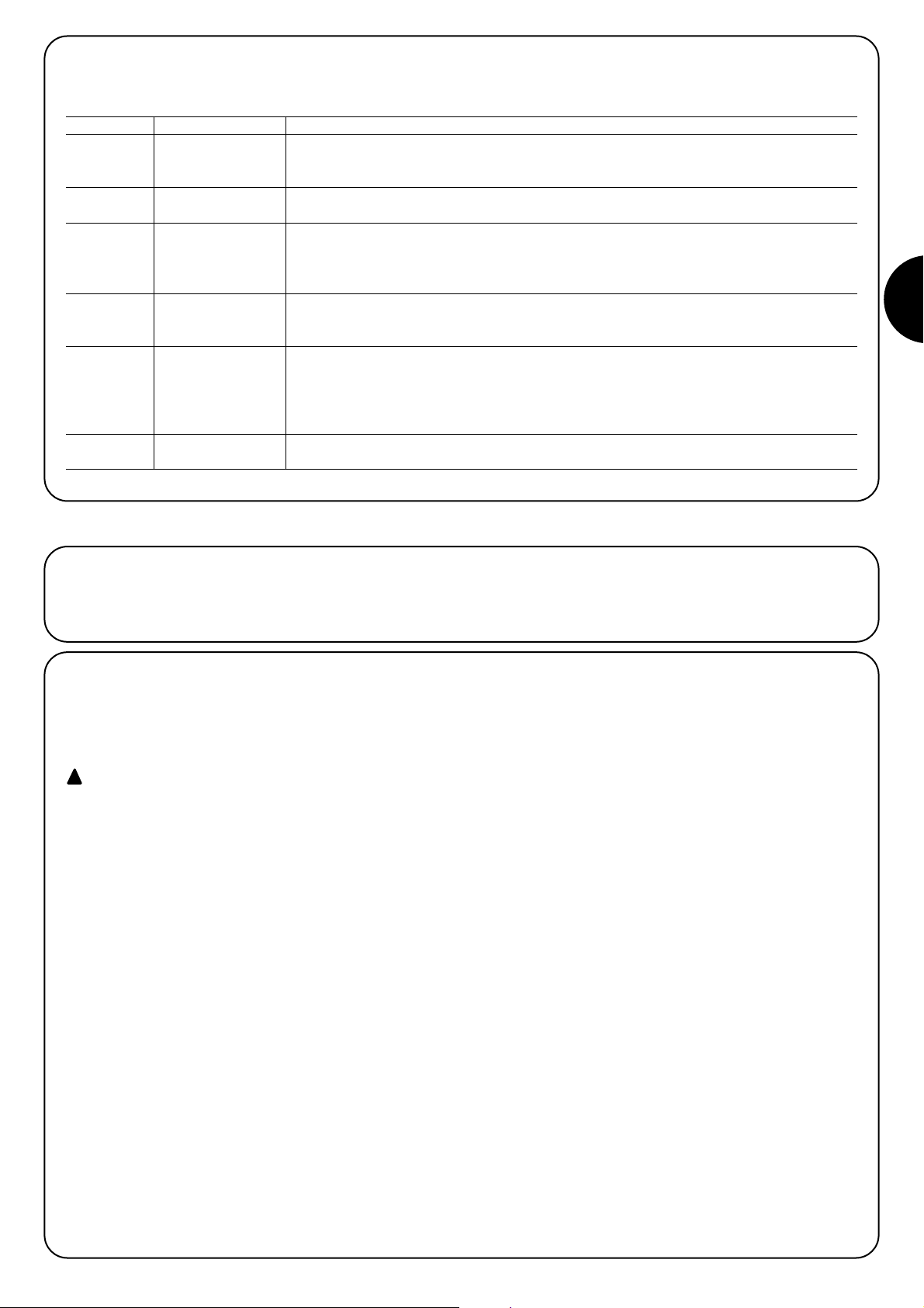
71
F
Avant de commencer la phase de contrôle et de mise en service de
l’automatisme, il est conseillé de décrocher le chariot et de mettre la
porte à mi-course environ de sorte qu’il puisse se déplacer aussi
bien en ouverture qu’en fermeture.
4) Vérifications finales et mise en service
4.1) Branchement au secteur
Pour l’alimentation électrique de SPIN, il suffit de brancher sa fiche
dans une prise de courant. Utiliser éventuellement un adaptateur en
vente dans le commerce si la fiche de SPIN ne correspond pas à la
prise disponible.
Ne pas couper ni enlever le câble fourni avec SPIN.
S’il n’y a pas de prise disponible, le branchement de l’alimentation à SPIN doit être effectué par du personnel spécialisé, qualifié, en possession des critères requis et dans
le respect des lois, normes et règlements.
La ligne électrique d’alimentation doit être protégée
contre les courts-circuits et le défaut de mise à la terre; il
doit y avoir un dispositif permettant de couper l’alimentation durant l’installation ou la maintenance de SPIN (la
fiche plus la prise peut convenir)
Dès que l’opérateur SPIN est alimenté, il est conseillé de faire
quelques vérifications élémentaires:
1. Vérifier que la led OK clignote régulièrement à la fréquence d’un
clignotement à la seconde.
2. Vérifier que le moteur ne commande pas le mouvement de la porte et que l’éclairage automatique est éteint.
Si ce n’est pas le cas, il faut couper immédiatement l’alimentation de
la logique de commande et contrôler plus attentivement les
connexions électriques.
D’autres informations utiles pour la recherche et le diagnostic des
pannes sont fournies dans le chapitre «7.6 Résolution des problèmes».
!
3.5) Description des connexions électriques
Ce paragraphe contient une brève description des connexions électriques; d’autres informations se trouvent dans le paragraphe «7.3 Ajout ou
retrait de dispositifs».
Bornes Fonction Description
1 – 2 Antenne entrée pour la connexion de l’antenne pour récepteur radio. L’antenne est incorporée sur LUCY B.
Il est également possible d’utiliser une antenne externe ou de laisser le tronçon de câble, qui fait
office d’antenne, déjà présent dans la borne.
3 – 4 Pas à pas entrée pour les dispositifs qui commandent le mouvement; on peut y connecter des contacts du
type «normalement ouvert».
5 – 6 Stop entrée pour les dispositifs qui bloquent ou éventuellement arrêtent la manœuvre en cours; en
adoptant certaines solutions sur l’entrée, il est possible de connecter des contacts du type
«normalement fermé», du type «normalement ouvert» ou un dispositif à résistance constante.
D’autres informations sur STOP sont fournies dans le paragraphe «7.3.1 Entrée STO ».
3 - 7 Photo entrée pour les dispositifs de sécurité, tels que les photocellules. Ils interviennent durant la fermeture
en inversant la manœuvre. Il est possible de connecter des contacts du type «normalement fermé».
D’autres informations sur PHOTO sont fournies dans le paragraphe «7.3.2 Entrée PHOTO».
6 – 8 Photo-test chaque fois qu’une manœuvre est activée, tous les dispositifs de sécurité sont contrôlés et la
manœuvre ne démarre que si le test est positif. Cela est possible grâce à l’utilisation d’un type de
connexion particulier; les émetteurs des photocellules «TX» sont alimentés séparément par rapport
aux récepteurs «RX». D’autres informations sur la connexion sont fournies dans le paragraphe
«7.2.3 Entrée PHOTO».
9 – 10 Clignotant sur cette sortie, il est possible de raccorder un clignotant NICE «LUCY B» à une ampoule 12 V 21 W
type auto. Durant la manœuvre, il clignote à raison de: 0,5 s allumé et 0,5 s éteint.
Page 72

72
4.2) Reconnaissance des positions d’ouverture et
de fermeture de la porte.
Il est nécessaire de faire reconnaître à la logique de commande les
positions d’ouverture et de fermeture de la porte. Durant cette phase, la course de la porte est détectée par la butée mécanique d’arrêt de fermeture et par la butée d’ouverture. En plus des positions,
c’est également durant cette phase qu’est relevée et mémorisée la
configuration de l’entrée STOP et la présence ou non de la
connexion en mode «Photo-test» de l’entrée PHOTO.
1. Vérifier que la courroie d’entraînement est bien tendue et que les deux butées mécaniques sont bien bloquées.
2. Accrocher le chariot.
3. Appuyer sur les touches []et [ Set ] sans relâcher.
4. Relâcher les touches quand la manœuvre commence (au bout d’environ 3 s).
5. Attendre que la logique exécute la phase de reconnaissance: fermeture, ouverture et refermeture de la porte.
6. Appuyer sur la touche [PP] pour exécuter une manœuvre complète d’ouverture.
7. Appuyer sur la touche [PP] pour exécuter la fermeture.
Durant ces manœuvres, la logique de commande mémorise la force nécessaire dans les mouvements d’ouverture et de fermeture.
Si, à la fin de la reconnaissance, les led L2 et L3 clignotent, cela signifie qu’il y a une erreur; voir le paragraphe «7.6 Résolution des problèmes».
Il est important que ces premières manœuvres ne soient pas interrompues, par exemple par une commande d’arrêt.
Si cela devait se produire, il faudrait recommencer la reconnaissance à partir du point 1.
La phase de reconnaissance des positions et de la configuration des entrées STOP et PHOTO peut être refaite à tout moment même après
l’installation (par exemple si l’une des butées mécaniques est déplacée); il suffit de recommencer à partir du point 1.
Durant la recherche des positions, si la courroie n’est pas suffisamment tendue, il peut se produire un glissement entre
la courroie et le pignon. Si c’est le cas, interrompre la reconnaissance en appuyant sur la touche [Stop]; tendre la courroie
en vissant l’écrou M8 (D) comme indiqué sur la figure 11; répéter alors l’opération de reconnaissance à partir du point 1.
La reconnaissance des positions d’ouverture et de fermeture de la porte ne peut s’effectuer que lorsque le temps de
mémorisation et d’effacement des émetteurs radio (voir paragraphe 4.5 « Récepteur radio ») s’est écoulé
!
!
34
4.3) Vérification du mouvement de la porte
Après la reconnaissance des positions d’ouverture et de fermeture,
il est conseillé d’effectuer quelques manœuvres pour vérifier que le
mouvement de la porte est correct.
1. Appuyer sur la touche [PP] pour commander une manœuvre
d’ouverture; vérifier que l’ouverture de la porte s’effectue régulièrement sans variation de vitess; la porte ne doit ralentir et s’arrêter, à 2 ou 3 cm de la butée, que lorsqu’elle se trouve entre 30 et
20 cm de la butée mécanique d’ouverture.
2. Appuyer sur la touche [PP] pour commander une manœuvre de
fermeture; vérifier que la fermeture de la porte s’effectue régulièrement sans variation de vitesse; la porte ne doit ralentir et s’arrêter contre la butée que lorsqu’elle se trouve entre 30 et 20 cm
de la butée mécanique de fermeture. Puis une brève manœuvre
d’ouverture est exécutée pour libérer la tension de la courroie.
3. Durant la manœuvre, vérifier que le clignotant (s’il est présent) clignote à une fréquence régulière de 0,5 s allumé et 0,5 s éteint.
4. Effectuer différentes manœuvres d’ouverture et de fermeture pour
mettre en évidence les éventuels défauts de montage et de réglage ou d’autres anomalies comme les points de plus grande friction.
5. Vérifier que les fixations de l’opérateur, du rail et des butées
mécaniques sont solides, stables et suffisamment résistantes
même en cas de brusques accélérations ou de décélérations du
mouvement de la porte.
4.4) Fonctions préprogrammées
La logique de commande de SPIN dispose de certaines fonctions programmables; en usine, ces fonctions sont réglées suivant une configuration qui devrait satisfaire la plupart des automatisations; quoiqu’il en
soit, les fonctions peuvent être modifiées à tout moment à l’aide d’une
procédure de programmation particulière: voir pour ce faire le paragraphe «7.2 Programmations».
4.5) Récepteur radio
Pour la commande à distance de SPIN, un récepteur radio est incorporé à la logique de commande, ce récepteur opère à la fréquence
de 433,92 MHz compatible avec les typologies d’émetteurs suivantes:
Comme le type de codage est différent, le premier émetteur activé
détermine aussi la typologie de ceux qui pourront être activés ensuite. Il est possible de mémoriser jusqu'à 160 émetteurs.
La mémorisation et l’effacement des émetteurs doivent être
effectués dans les 10 secondes qui suivent la mise sous
tension. Durant ce laps de temps, la touche sur la logique
de commande [RADIO] est dédiée à la mémorisation et à
l’effacement radio. Quand 10 secondes se sont écoulées
depuis le dernier clignotement de la LED L1 ou depuis la
dernière pression, la touche est désactivée et la LED L1 est
dédiée aux fonctions de programmation. Pour signaler la fin
du laps de temps réservé à la mémorisation radio, 1 clignotement de l'éclairage automatique se produit.
FLO FLO1 – FLO2 – FLO4
VERY VE
FLOR FLOR1 – FLOR2 – FLOR4
VERY VR
ERGO1 – ERGO4 – ERGO6
PLANO1 – PLANO4 – PLANO6
Émetteurs ligne OPERA
SMILO SM2 – SM4
Tableau 6: émetteurs
Page 73

73
F
1 Commande « PP »
2 Commande « Ouverture partielle »
3 Commande « Ouverture »
4 Commande « Fermeture »
Tableau 8: commandes disponibles en Mode II
4.5.1) Mémorisation des émetteurs
Chaque émetteur radio est reconnu par le récepteur radio à travers un «code» différent de tous les autres émetteurs. Il faut donc effectuer
une phase de «mémorisation» à travers laquelle le récepteur est préparé à reconnaître chaque émetteur. La mémorisation des émetteurs peut
se faire de deux manières:
Mode I: dans ce mode, la fonction des touches de l’émetteur est
fixe et chaque touche correspond dans la logique à la commande
indiquée dans le tableau 7; on effectue une seule phase pour chaque
émetteur dont sont mémorisées toutes les touches; durant cette
phase, la touche enfoncée n’a pas d’importance et une seule place
est occupée dans la mémoire. En mode I, un émetteur ne peut normalement commander qu’un seul automatisme.
Mode II: dans ce mode, chaque touche de l’émetteur peut être associée à l’une des 4 commandes possibles de la logique, indiquées dans
le tableau 8; pour chaque phase, une seule touche, celle qui est enfoncée durant la phase de mémorisation, est mémorisée. Dans la mémoire, une seule place est occupée pour chaque touche mémorisée.
En mode II, les différentes touches du même émetteur peuvent être
utilisées pour donner des commandes différentes au même automatisme ou pour commander des automatismes différents. Par
exemple, dans le tableau 9, seul l’automatisme «A» est commandé
et les touches T3 et T4 sont associées à la même commande; ou
bien, dans l’exemple du tableau 10, les 3 touches commandent 3
automatismes différents: «A» (touches T1 et T2), «B» (touche T3) et
«C» (touche T4).
Comme les procédures de mémorisation ont un temps limite de
10 s, il faut lire d’abord les instructions fournies dans les paragraphes suivants avant de les exécuter.
!
Touche T1 Commande « PP »
Touche T2 Commande « Ouverture partielle »
Touche T3 Commande « Ouverture »
Touche T4 Commande « Fermeture »
Tableau 7: mémorisation Mode I
Touche T1 Commande « Ouverture » Automatisme A
Touche T2 Commande « Fermeture » Automatisme A
Touche T3 Commande « Ouverture partielle » Automatisme A
Touche T4 Commande « Ouverture partielle » Automatisme A
Tableau 9: 1erexemple de mémorisation en Mode II
Touche T1 Commande « Ouverture » Automatisme A
Touche T2 Commande « Fermeture » Automatisme A
Touche T3 Commande « PP » Automatisme B
Touche T4 Commande « PP » Automatisme C
Tableau 10: 2eexemple de mémorisation en Mode II
Note: les émetteurs à un canal disposent uniquement de la touche T1, les
émetteurs à deux canaux disposent uniquement des touches T1 et T2.
1. Appuyer sans relâcher sur la touche radio sur la logique de commande (pendant 4 s environ).
4s
2. Relâcher la touche quand la led radio sur la logique de commande s’allume.
3. Dans les 10 s qui suivent, appuyer pendant au moins 3 s sur l’une des touches de l’émetteur à mémoriser.
3s
4. Si la mémorisation a été effectuée correctement, la led radio sur la logique de commande émettra
3 clignotements. x3
S’il y a d’autres émetteurs à mémoriser, répéter le point 3 dans les 10 s.
La phase de mémorisation se termine automatiquement si aucun nouveau code n’est mémorisé dans les 10 secondes qui suivent.
Tableau 11: pour mémoriser un émetteur en mode I Exemple
4.5.2) Mémorisation en Mode I
35
1. Appuyer sur la touche radio sur la logique de commande un nombre de fois équivalent à la commande
voulue suivant le tableau 8. 1....4
2. Vérifier que la led radio sur la logique de commande émet un nombre de clignotements équivalent à la
commande voulue. 1....4
3. Dans les 10 s qui suivent, appuyer pendant au moins 3 s sur la touche voulue de l’émetteur à mémoriser.
3s
4. Si la mémorisation a été effectuée correctement, la led sur le récepteur émettra 3 clignotements.
x3
S’il y a d’autres émetteurs à mémoriser pour la même commande, répéter le point 3 dans les 10 s.
La phase de mémorisation se termine automatiquement si aucun nouveau code n’est mémorisé dans les 10 secondes qui suivent.
Tableau 12: pour mémoriser la touche d’un émetteur en mode II Exemple
4.5.3) Mémorisation en Mode II
Page 74

74
1. Avec les deux émetteurs, se placer dans le rayon d’action de l’automatisme et exécuter les opérations
suivantes: 5s
2. Appuyer pendant au moins 5 s sur la touche sur le nouvel émetteur radio, puis relâcher.
1s 1s 1s
3. Appuyer lentement 3 fois sur la touche sur l’émetteur radio déjà mémorisé.
1s
Maintenant, le nouvel émetteur radio sera reconnu par le récepteur et prendra les caractéristiques qu’avait celui qui était déjà mémorisé.
S’il y a d’autres émetteurs à mémoriser, répéter les mêmes opérations pour chaque nouvel émetteur.
Tabella 13: per memorizzare un trasmettitore “a distanza” Exemple
4.5.4) Mémorisation «à distance»
Il est possible de mémoriser un nouvel émetteur sans agir directement
sur la petite touche du récepteur. Pour ce faire, il faut disposer d’une
télécommande déjà mémorisée et en fonction. Le nouvel émetteur
«héritera » des caractéristiques de celui qui est déjà mémorisé; cela
signifie que, si le premier émetteur est mémorisé en mode I, le nouveau
sera lui aussi mémorisé en mode I et l’on pourra appuyer sur n’importe quelle touche des émetteurs. En revanche, si le premier émetteur est
mémorisé en mode II, le nouveau devra lui aussi être mémorisé en
mode II; il devient alors important d’appuyer, sur le premier émetteur,
sur la touche relative à la commande voulue et, sur le nouvel émetteur,
sur la touche à laquelle on souhaite associer cette commande.
La mémorisation à distance peut s’effectuer dans tous
les récepteurs qui se trouvent dans le rayon de portée de
l’émetteur; il faut donc alimenter uniquement celui qui est
concerné par l’opération.
!
Tableau 13: pour mémoriser un émetteur «à distance»
1. Appuyer sans relâcher sur la touche radio sur la logique de commande.
2.
Attendre que la led radio s’allume puis qu’elle s’éteigne et enfin qu’elle émette 3 clignotements.
x3
3. Relâcher la touche radio exactement durant le 3e clignotement.
4. Si la procédure a été effectuée correctement, au bout de quelques instants, la led émettra 5 clignotements.
x5
Tableau 14: pour effacer tous les émetteurs. Exemple
4.5.5) Effacement des émetteurs radio
Il s’agit de la phase la plus importante dans la réalisation de l’automatisation afin de garantir une sécurité maximale.
L’essai peut aussi être utilisé comme vérification périodique des dispositifs qui composent l’automatisme.
L’essai de toute l’installation doit être effectué par du personnel spécialisé et qualifié qui devra se charger des essais
requis en fonction des risques présents et vérifier le respect
de ce qui est prévu par les lois, les normes et les règlements,
en particulier toutes les prescriptions de la norme EN 12445
qui détermine les méthodes d’essai pour la vérification des
automatismes pour les portails et les portes.
!
5) Essai et mise en service
5.1) Essai
Chaque élément de l’automatisme, tels que les bords sensibles, les
photocellules, l’arrêt d’urgence, etc. demande une phase spécifique
d’essai; pour ces dispositifs, il faudra effectuer les procédures figurant dans leurs manuels d’instructions respectifs.
Pour l’essai de SPIN, effectuer les opérations suivantes:
1. Vérifier que tout ce qui est prévu dans le chapitre «1 AVERTISSEMENTS» est rigoureusement respecté.
2. Débrayer la porte en tirant sur le cordon de débrayage vers le
bas. Vérifier qu’il est possible de déplacer manuellement la porte
en ouverture et en fermeture avec une force inférieure ou égale à
225 N.
3. Raccrocher le chariot.
4. En utilisant le sélecteur ou l’émetteur radio, effectuer des essais
de fermeture et d’ouverture de la porte et vérifier que le mouvement correspond à ce qui est prévu.
5. Il faut effectuer plusieurs essais afin d’évaluer la régularité du mouvement de la porte et les éventuels défauts de montage ou de
réglage ainsi que la présence de points de frottement particuliers.
6. Vérifier un par un le fonctionnement correct de tous les dispositifs de sécurité présents dans l’installation (photocellules, bords
sensibles, etc.); en particulier, chaque fois qu’un dispositif intervient, la led OK sur la logique de commande doit émettre 2 clignotements plus rapides qui confirment qu’elle reconnaît l’événement.
7. Pour vérifier le fonctionnement des photocellules et, en particulier,
pour contrôler qu’il n’y a pas d’interférences avec d’autres dispositifs, passer un cylindre de 5 cm de diamètre et de 30 cm de
longueur sur l’axe optique, d’abord à proximité de l’émetteur,
puis du récepteur et enfin au centre, entre les deux, et vérifier que
dans tous les cas le dispositif intervient en passant de l’état d’actif à l’état d’alarme et vice versa; pour finir, vérifier que cela provoque dans la logique l’action prévue; exemple: dans la
manœuvre de fermeture, vérifier que cette action provoque l’inversion du mouvement.
8. Si l’on n’a pas remédier aux situations de risque liées au mouvement de la porte à travers la limitation de la force d’impact, il faut
effectuer la mesure de la force suivant les prescriptions de la norme EN 12445. Si le réglage de la « Vitesse » et le contrôle de la
« Force moteur » sont utilisés pour aider le système à réduire la
force d’impact, essayer et trouver les réglages qui garantissent
les meilleurs résultats.
Page 75

75
F
5.2) Mise en service
La mise en service ne peut être faite que si toutes les phases d’essai ont été exécutées avec un résultat positif. La mise en service partielle ou dans des situations «provisoires» n’est pas autorisée.
1. Réaliser et conserver au moins 10 ans le fascicule technique de
l’automatisation qui devra comprendre au moins: le dessin d’ensemble de l’automatisation, le schéma des connexions électriques,
l’analyse des risques et les solutions adoptées, la déclaration de
conformité du fabricant de tous les dispositifs utilisés (pour SPIN,
utiliser la déclaration CE de conformité jointe), un exemplaire du
manuel d’instructions et du plan de maintenance de l’automatisme.
2. Fixer de manière permanente sur la porte une étiquette ou une
plaque indiquant les opérations à effectuer pour le débrayage et
la manœuvre manuelle (utiliser les figures contenues dans les
«Instructions et recommandations destinées à l’utilisateur de
l’opérateur SPIN»).
3. Fixer de manière permanente sur la porte une étiquette ou une
plaque avec cette image (hauteur minimum: 60 mm).
4. Appliquer sur la porte une plaquette contenant au moins les données suivantes: type d’automatisme, nom et adresse du
constructeur (responsable de la «mise en service»), numéro de
matricule, année de construction et marque «CE».
5. Remplir et remettre au propriétaire la déclaration de conformité
de l’automatisme.
6. Rédiger et remettre au propriétaire de l’automatisme le manuel
«Instructions et recommandations pour l’utilisation de l’automatisme».
7. Rédiger et remettre au propriétaire le plan de maintenance de l’automatisme (qui doit regrouper toutes les prescriptions pour la
maintenance de tous les dispositifs de l’automatisme).
Avant de mettre en service l’automatisme, informer le propriétaire, de manière adéquate et par écrit (par exemple dans le manuel
d’instructions et de recommandations pour l’utilisation de l’automatisme), sur les dangers et les risques encore présents.
36
Ce chapitre contient les informations nécessaires pour la réalisation du plan de maintenance et la mise au rebut de SPIN.
6) Maintenance et mise au rebut
6.1) Maintenance
Pour maintenir un niveau de sécurité constant et pour garantir la
durée maximum de tout l’automatisme, il faut effectuer une maintenance régulière.
La maintenance doit être effectuée dans le respect
absolu des consignes de sécurité du présent manuel et
selon les prescriptions des lois et des normes en vigueur.
Si d’autres dispositifs sont présents, suivre ce qui est prévu dans
leurs plans de maintenance respectifs.
1. Pour SPIN, il faut effectuer une maintenance programmée au
maximum dans les 6 mois ou quand 3000 manœuvres ont été
effectuées depuis la dernière intervention de maintenance.
2. Déconnecter toutes les sources d’alimentation électrique.
3. Vérifier l’état de détérioration de tous les matériaux qui composent l’automatisme avec une attention particulière pour les phénomènes d’érosion ou d’oxydation des parties de la structure;
remplacer les parties qui ne donnent pas de garanties suffisantes.
4. Vérifier l’état d’usure des parties en mouvement: courroie, chariot, pignons et toutes les parties de la porte; remplacer les parties usées.
Reconnecter les sources d’alimentation électrique et effectuer
tous les essais et les contrôles prévus dans le paragraphe «5.1
Essai».
!
6.2) Mise au rebut
SPIN est constitué de différents types de matériaux dont certains
peuvent être recyclés: acier, aluminium, plastique, câbles électriques; d’autres devront être mis au rebut: batteries et cartes électroniques.
Certains composants électroniques et les batteries
peuvent contenir des substances polluantes; ne pas les
abandonner dans la nature. S’informer sur les systèmes
de recyclage ou de mise au rebut et respecter les normes
locales en vigueur.
1. Déconnecter l’alimentation électrique de
2. Démonter tous les dispositifs et accessoires, en suivant la procédure inverse à celle qui est décrite dans le chapitre 3 «Installation».
3. Séparer le plus possible les parties qui peuvent ou doivent être
recyclées ou éliminées de manière différente; par exemple, séparer les parties métalliques des parties en plastique, les cartes
électroniques, etc.
4. Trier et confier les différents matériaux ainsi séparés aux centres
agréés de recyclage et de traitement des déchets qui existent localement.
!
Page 76

76
Ce chapitre explique les possibilités de programmation, de personnalisation, de diagnostic et de recherche des pannes sur SPIN.
7) Approfondissements
RADIO Dans les 10 secondes qui suivent la mise sous tension, exécute la fonction
« RADIO », ce qui permet de mémoriser et d’effacer les émetteurs radio à uti
liser avec SPIN. Après ce laps de temps, la touche n’est plus utilisée.
Stop La touche « STOP » permet d’arrêter la manœuvre;
SET Si elle est pressée pendant plus de 5 secondes, elle permet d’entrer en
programmation selon les modalités décrites ci-dessous.
PP La touche « PP » permet de commander l’ouverture et la fermeture de la
porte ou de déplacer vers le haut ou le bas le point de programmation.
7.1) Touches de programmation
Sur la logique de commande de SPIN se trouvent 3 touches qui peuvent être utilisées aussi bien pour la commande de la logique durant les essais que pour les programmations:
7.2) Programmations
La logique de commande de SPIN possède plusieurs fonctions programmables; le réglage des fonctions s’effectue au moyen de 2
touches présentes sur la logique: []et [Set]; elles sont signa-
lées par 3 LED: L1, L2, L3.
Les programmations se divisent en 2 groupes:
Programmation lors de la mise sous tension: ce type de programmation s’effectue tout de suite après la mise sous tension de SPIN.
Pour activer ce type de programmation, maintenir la touche [Set]
enfoncée durant la mise sous tension de la logique de commande.
Programmation standard: ce type de programmation peut s’effectuer à tout moment et s’active en maintenant la touche [Set] enfoncée.
Pour les deux types de programmation, les fonctions programmables disponibles sont réparties sur deux niveaux:
Premier niveau: fonctions réglables en mode ON-OFF (actif ou
non actif); dans ce cas, chaque LED (L1, L2, L3) indique une fonction; si elle est allumée, la fonction est active, si elle est éteinte la
fonction n’est pas active (voir tableaux 15 et 15a).
Deuxième niveau: paramètres réglables sur une échelle de
valeurs (valeurs de 1 à 3); dans ce cas, chaque LED (L1, L2, L3)
indique la valeur réglée parmi les 3 possibles (voir tableaux 17 et
17a).
37
N° Description Exemple
L1 Sensibilité variable Cette fonction permet d’activer ou de désactiver la sensibilité avec laquelle les obstacles sont détectés.
Par défaut, la sensibilité de ce système est variable (LED L1 éteinte): plus de sensibilité là où le moteur
fait peu d’effort, moins de sensibilité là où il fait plus d’effort. Cela a pour but de détecter les obstacles
avec une précision maximale. Il est possible de désactiver la sensibilité variable; restent alors les 3
niveaux « fixes » de force du moteur (LED L1 allumée).
L2
Photo-test/Serrure électrique
Cette fonction permet d’activer la sortie 8 du bornier pour le fonctionnement avec photo-test ou avec
serrure électrique. Par défaut, la sortie 8 test est activée pour la fonction « photo-test » (LED L2 éteinte).
Il est aussi possible, dans la logique de commande de SPIN, de programmer la sortie pour la
commande d’une serrure électrique (LED L2 allumée).
L3 Ouverture partielle Cette fonction permet de choisir la position d’ouverture partielle courte ou longue. Par défaut, l’ouverture
partielle est réglée sur « longue » (environ 1 m, LED L3 allumée). Il est aussi possible de programmer
l’ouverture partielle courte (environ 15 cm, LED L3 éteinte).
À la fin de la procédure de « programmation lors de la mise sous tension », les LED L1, L2 et L3 indique l’état des fonctions de « pro-
grammation standard ».
Tableau 15: liste des fonctions programmables de la « programmation lors de la mise sous tension »
7.2.1) Fonctions du premier niveau (fonctions ON-OFF)
N° Description Exemple
L1 Vitesse de fermeture Cette fonction permet de choisir la vitesse du moteur durant la manœuvre de fermeture entre 2 niveaux:
« rapide » et « lente ». Par défaut, la vitesse est réglée sur « rapide » (LED L1 allumée). En désactivant la
fonction, il est possible de régler la vitesse sur « lente » (LED L1 éteinte).
L2 Vitesse d’ouverture Cette fonction permet de choisir la vitesse du moteur durant la manœuvre d’ouverture entre 2 niveaux:
« rapide » et « lente ». Par défaut, la vitesse est réglée sur « rapide » (LED L2 allumée). En désactivant la
fonction, il est possible de régler la vitesse sur « lente » (LED L2 éteinte).
L3 Fermeture automatique Cette fonction permet une fermeture automatique de la porte après le temps de pause programmé; le temps
de pause est réglé par défaut à 30 secondes mais peut être modifié à 15 ou 60 secondes. Par défaut, le
fonctionnement est « semi-automatique » car la fermeture automatique est désactivée (LED L3 éteinte).
Durant le fonctionnement normal de SPIN, les LED L1, L2 et L3 sont allumées ou éteintes suivant l’état de la fonction à laquelle elles correspondent dans la programmation standard: par exemple, L3 est allumée si la « fermeture automatique » est active. L1 indique aussi
l’état de la fonction « radio » durant les 10 s qui suivent la mise sous tension.
Tableau 15a: liste des fonctions programmables de la « programmation standard »
Page 77

77
F
7.2.2) Programmation du premier niveau (fonctions ON-OFF)
Par défaut, les fonctions du premier niveau sont programmées conformément aux descriptions des tableaux 15 et 15a mais peuvent être
modifiées à tout moment comme indiqué dans les tableaux 16 et 16a. Faire attention durant la procédure car il ne faut pas que s’écoulent
plus de 10 s entre la pression d’une touche et l’autre: dans le cas contraire, la procédure se termine automatiquement et mémorise les modifications effectuées jusqu’à ce momentlà.
1. Éteindre SPIN (par exemple en enlevant le fusible F1).
2. Presser et maintenir enfoncée la touche [Set].
3. Allumer SPIN (par exemple en mettant le fusible F1).
4. Attendre le clignotement de mise en marche de la logique de commande puis maintenir la touche [Set]
enfoncée jusqu'à ce que L1 commence à clignoter (environ 6 s). L1 6s
5. Relâcher la touche [Set] quand la LED L1 commence à clignoter.
L1
6. Presser la touche []pour déplacer la LED clignotante sur la LED qui correspond à la fonction
à modifier.
7. Presser la touche [Set] pour changer l’état de la fonction (clignotement bref = OFF;
clignotement long = ON).
8. Attendre 10 s pour sortir de la programmation pour cause de temps maximum écoulé.
10s
Note: les points 6 et 7 peuvent être répétés au cours de la même phase de programmation pour mettre d’autres fonctions en mode ON ou OFF.
Tableau 16: pour changer les fonctions ON-OFF de la programmation lors de la mise sous tension Exemple
SET
SET
SET
SET
1. Presser et maintenir enfoncée la touche [Set] pendant 3 s environ.
3s
2. Relâcher la touche [Set] quand la LED L1 commence à clignoter.
L1
3. Presser la touche []pour déplacer la LED clignotante sur la LED qui correspond à la fonction
à modifier.
4. Presser la touche [Set] pour changer l’état de la fonction (clignotement bref = OFF;
clignotement long = ON).
5. Attendre 10 s pour sortir de la programmation pour cause de temps maximum écoulé.
10s
Note: les points 3 et 4 peuvent être répétés au cours de la même phase de programmation pour mettre d’autres fonctions en mode ON ou OFF.
Tableau 16a: pour changer les fonctions ON-OFF de la programmation standard Exemple
SET
SET
SET
Page 78
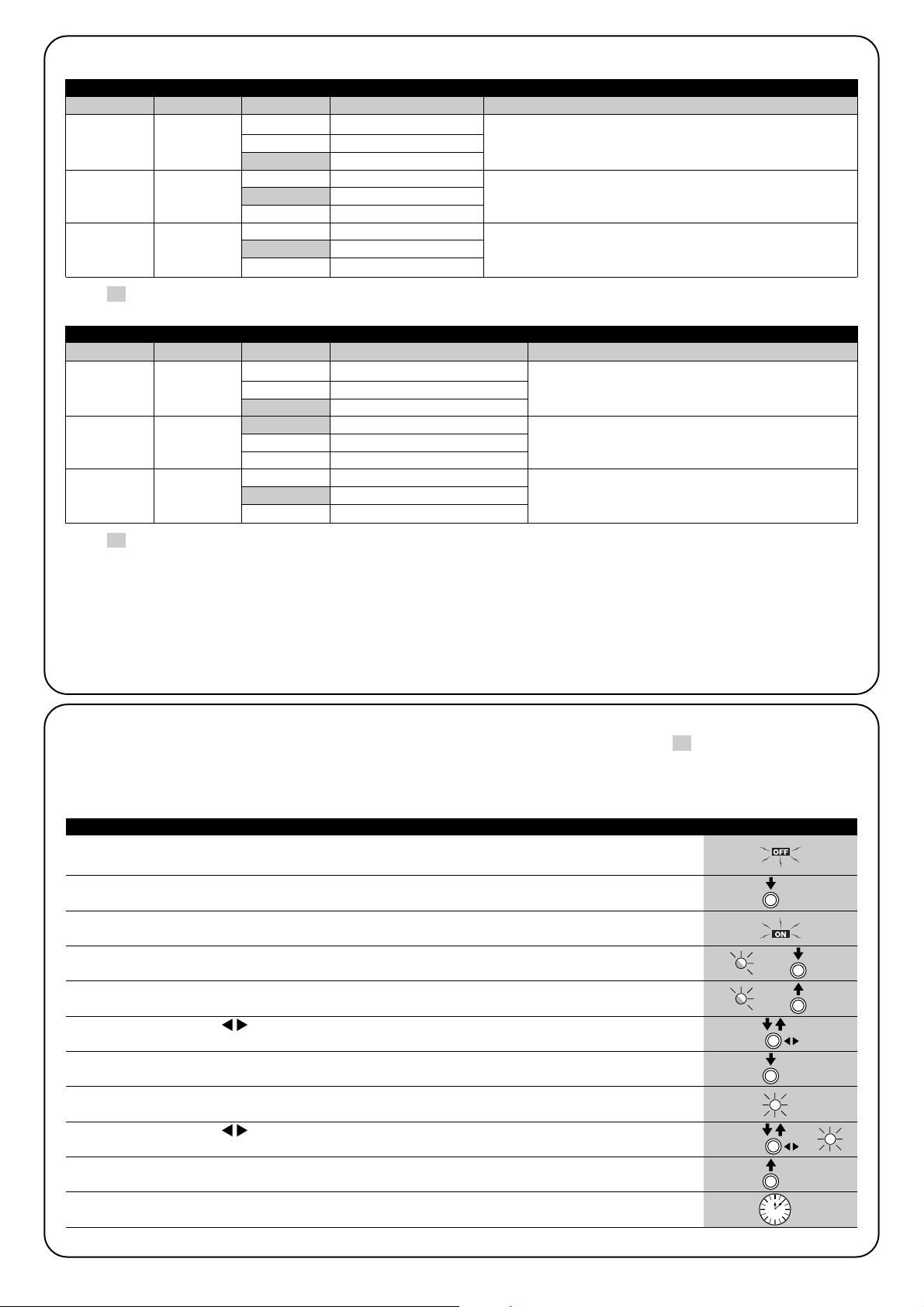
78
Sensibilité
Variable
Réajustement
de la courroie
cinghia
Ralentissement
en fermeture
Élevée
Moyenne
Basse
Aucun réajustement
Réajustement minimum
Réajustement maximum
Court
Moyen
Long
7.2.3) Fonctions du deuxième niveau (paramètres réglables)
Tableau 17: liste des fonctions programmables de deuxième niveau de la « programmation lors de la mise sous tension »
LED d’entrée Paramètre LED (niveau) valeur Description
Quand la sensibilité variable est activée, il est possible de la régler
sur 3 seuils d’intervention. La sensibilité variable élevée est adaptée aux portes de petites dimensions correctement équilibrées.
Règle la mesure du réajustement de la courroie. Après la fermeture complète de la porte, une manœuvre d’ouverture extrêmement brève, réglable avec ce paramètre, est commandée.
Règle la longueur du ralentissement durant la manœuvre de fermeture.
Note: “ ” représente le réglage par défaut.
L1
L2
L3
L1
L2
L3
L1
L2
L3
L1
L2
L3
7.2.4) Programmation du deuxième niveau (paramètres réglables)
Par défaut, les paramètres réglables sont réglés comme cela est décrit dans les tableaux 17 et 17a avec: « » mais ils peuvent être modifiés à tout moment comme l’indiquent les tableaux 18 et 18a. Faire attention durant la procédure car il ne faut pas que s’écoulent plus de
10 s entre la pression d’une touche et l’autre: dans le cas contraire, la procédure se termine automatiquement et mémorise les modifications
effectuées jusqu’à ce moment-là.
1. Éteindre SPIN (par exemple en enlevant le fusible F1).
2. Presser et maintenir enfoncée la touche [Set].
3. Allumer SPIN (par exemple en mettant le fusible F1).
4. Attendre le clignotement de mise en marche de la logique de commande puis maintenir la touche [Set]
enfoncée jusqu'à ce que L1 commence à clignoter (environ 6 s). L1 6s
5. Relâcher la touche [Set] quand la LED L1 commence à clignoter.
L1
6. Presser la touche []pour déplacer la LED clignotante sur la LED d’entrée qui correspond au
paramètre à modifier.
7. Presser et maintenir enfoncée la touche [Set]; la pression sur la touche [Set] doit être maintenue
pendant toute la durée des phases 5 et 6.
8. Attendre environ 3 s puis la LED qui correspond au niveau actuel du paramètre à modifier s’allumera.
3s
9. Presser la touche []pour déplacer la LED qui correspond à la valeur du paramètre.
10. Relâcher la touche [Set].
11. Attendre 10 s pour sortir de la programmation pour cause de temps maximum écoulé.
10s
Note: les points de 6 à 10 peuvent être répétés au cours de la même phase de programmation pour régler plusieurs paramètres.
Tableau 18: pour modifier les paramètres réglables de la programmation lors de la mise sous tension Exemple
SET
SET
SET
SET
Force moteur
Fonction P.P.
Temps de
pause
Basse
Moyenne
Élevée
Ouverture - stop - fermeture- ouverture
Ouverture - stop – fermeture - stop
Fonctionnement collectif
15 secondes
30 secondes
60 secondes
Tableau 17a: liste des fonctions programmables de deuxième niveau de la « programmation standard »
LED d’entrée Paramètre LED (niveau) valeur Description
Règle la force maximum que le moteur peut développer
pour manœuvrer la porte.
Règle la séquence de commandes associées à l’entrée
P.P. ou bien à la première commande radio (voir
tableaux 7 et 8).
Règle le temps de pause, à savoir le temps qui s’écoule avant la refermeture automatique. La fonction n’a
d’effet que si la fermeture automatique est active.
Note: “ ” représente le réglage par défaut.
Tous les paramètres peuvent être réglés librement sans aucune contre-indication; seul le réglage de la « force moteur » pourrait demander
une attention particulière:
• Il est déconseillé d’utiliser des valeurs de force élevées pour compenser le fait que le tablier a des points de friction anormaux; une force
excessive peut compromettre le fonctionnement du système de sécurité ou endommager le tablier.
• Si le contrôle de la « force moteur » est utilisé comme soutien du système pour la réduction de la force d’impact, après chaque réglage,
répéter la mesure de la force, comme le prévoit la norme EN 12445.
• L’usure et les conditions atmosphériques peuvent influencer le mouvement de la porte, périodiquement il faut recontrôler le réglage de la force.
L1
L2
L3
L1
L2
L3
L1
L2
L3
L1
L2
L3
SET
Page 79

79
F
1. Presser et maintenir enfoncée la touche [Set] pendant 3 s environ.
3s
2. Relâcher la touche [Set] quand la LED L1 commence à clignoter.
L1
3. Presser la touche []pour déplacer la LED clignotante sur la LED d’entrée qui correspond au
paramètre à modifier.
4. Presser et maintenir enfoncée la touche [Set]; la pression sur la touche [Set] doit être maintenue
pendant toute la durée des phases 5 et 6.
5. Attendre environ 3 s puis la LED qui correspond au niveau actuel du paramètre à modifier s’allumera.
6. Presser la touche []pour déplacer la LED qui correspond à la valeur du paramètre.
7. Relâcher la touche [Set].
8. Attendre 10 s pour sortir de la programmation pour cause de temps maximum écoulé.
10s
Note: les points de 3 à 7 peuvent être répétés au cours de la même phase de programmation pour régler plusieurs paramètres.
Tableau 18a: pour modifier les paramètres réglables de la programmation standard Exemple
SET
SET
SET
SET
7.2.5) Exemple de programmation du premier niveau (fonctions ON-OFF)
Comme exemple, nous indiquons la séquence d’opérations à effectuer pour modifier le réglage par défaut des fonctions, désactiver la fonction « sensibilité variable » (L1) et activer « l’ouverture partielle courte » (L3).
1. Éteindre SPIN (par exemple en enlevant le fusible F1).
2. Presser et maintenir enfoncée la touche [Set].
L1
3. Allumer SPIN (par exemple en mettant le fusible F1).
4. Attendre le clignotement de mise en marche de la logique de commande puis maintenir la touche [Set]
enfoncée jusqu'à ce que L1 commence à clignoter (environ 6 s). L1 6s
5. Relâcher la touche [Set].
6. Presser une fois la touche [Set] pour changer l’état de la fonction associée à L1 (sensibilité variable);
à présent la LED L1 clignote avec un clignotement long. L1
7. Presser 2 fois la touche []pour déplacer la LED clignotante sur la LED L3.
L3
8. Presser une fois la touche pour changer l’état de la fonction associée à L3 (ouverture partielle); à présent
la LED L3 clignote avec un clignotement long. L3
9. Attendre 10 s pour sortir de la programmation pour cause de temps maximum écoulé.
10s
Pendant l’attente précédant la sortie de la programmation, les LED L1 et L3 doivent rester allumées, ce qui indique que les fonctions « sensibilité variable désactivée » et « ouverture partielle courte » sont activées.
Tableau 19: exemple de programmation de premier niveau de la programmation lors de la mise sous tension
Exemple
SET
SET
SET
Comme exemple, nous indiquons les diverses opérations à effectuer pour modifier le réglage des fonctions par défaut pour activer les fonctions de « vitesse d’ouverture élevée » (L2) et « fermeture automatique » (L3).
1. Presser et maintenir enfoncée la touche [Set] pendant 3 s environ.
3s
2. Relâcher la touche [Set] quand la LED L1 commence à clignoter.
L1
3. Presser une fois la touche []pour déplacer la LED clignotante sur la LED L2.
L2
4. Presser une fois la touche [Set] pour changer l’état de la fonction associée à L2 (vitesse d’ouverture);
maintenant la LED L2 clignote avec un clignotement long. L2
5. Presser une fois la touche []pour déplacer la LED clignotante sur la LED L3.
L3
6. Presser une fois la touche [Set] pour changer l’état de la fonction associée à L3 (fermeture automatique);
maintenant la LED L3 clignote avec un clignotement long L3
7. Attendre 10 s pour sortir de la programmation pour cause de temps maximum écoulé.
10s
À la fin de ces opérations les LED L2 et L3 doivent rester allumées pour indiquer que les fonctions de « vitesse d’ouverture élevée » et « fermeture automatique » sont actives.
Tableau 19a: exemple de programmation de premier niveau de la programmation standard Exemple
SET
SET
SET
SET
SET
SET
Page 80

80
7.2.6) Exemple de programmation du deuxième niveau (paramètres réglables)
Comme exemple, nous indiquons la séquence d’opérations à effectuer pour modifier le réglage par défaut des paramètres, régler le « réajustement de la courroie » sur « aucun réajustement » (entrée sur L2 et niveau sur L1) et sélectionner le « ralentissement en fermeture » sur «
long »(entrée sur L3 et niveau sur L3).
1. Éteindre SPIN (par exemple en enlevant le fusible F1).
2. Presser et maintenir enfoncée la touche [Set].
3. Allumer SPIN (par exemple en mettant le fusible F1).
4. Attendre le clignotement de mise en marche de la logique de commande puis maintenir la touche [Set]
enfoncée jusqu'à ce que L1 commence à clignoter (environ 6 s). L1 6s
5. Relâcher la touche [Set].
6. Presser une fois la touche []pour déplacer la LED clignotante sur la LED L2.
L2
7. Presser et maintenir enfoncée la touche [Set]; la pression sur la touche [Set] doit être maintenue
pendant toute la durée des phases 8 et 9.
8. Attendre environ 3 s jusqu’à ce que la LED L2, qui correspond au niveau actuel du
« réajustement de la courroie », s’allume. L2 3s
9. Presser 2 fois la touche []pour déplacer la LED allumée sur L1 qui élimine le « réajustement
de la courroie ». L1
10. Relâcher la touche [Set].
11. Presser une fois la touche []pour déplacer la LED clignotante sur la LED L3.
L3
12. Presser et maintenir enfoncée la touche [Set]; la pression sur la touche [Set] doit être maintenue
pendant toute la durée des phases 13 et 14.
13. Attendre environ 3 s jusqu’à ce que la LED L2, qui correspond au niveau actuel du
« ralentissement en fermeture », s’allume. L2 3s
14. Presser 1 fois la touche []pour déplacer la LED allumée sur L3 qui représente la nouvelle valeur
du « ralentissement en fermeture ». L3
15. Relâcher la touche [Set].
16. Attendre 10 s pour sortir de la programmation pour cause de temps maximum écoulé.
10s
Tabella 20: Exemple de programmation de deuxième niveau de la programmation lors de la mise sous tension
Exemple
SET
SET
SET
SET
SET
SET
SET
Comme exemple, nous indiquons les diverses opérations à effectuer pour modifier le réglage des paramètres par défaut et régler la « force
moteur » sur élevée (entrée sur L1 et niveau sur L3) et augmenter le « temps de pause » à 60 s (entrée sur L3 et niveau sur L3).
1. Presser et maintenir enfoncée la touche [Set] pendant 3 s environ.
3s
2. Relâcher la touche [Set] quand la LED L1 commence à clignoter.
L1
3. Presser et maintenir enfoncée la touche [Set]; la pression sur la touche [Set] doit être maintenue
pendant toute la durée des phases 4 et 5.
4. Attendre environ 3 s jusqu’à ce que la LED L2, qui correspond au niveau actuel de la « force moteur »,
s’allume. L2 3s
5. Presser 1 fois la touche []pour déplacer la LED allumée sur L3 qui représente la nouvelle valeur
de la « force moteur ». L3
6. Relâcher la touche [Set].
7. Presser 2 fois la touche []pour déplacer la LED clignotante sur la LED L3.
L3
8. Presser et maintenir enfoncée la touche [Set]; la pression sur la touche [Set] doit être maintenue
pendant toute la durée des phases 9 et 10.
9. Attendre environ 3 s jusqu’à ce que la LED L2, qui correspond au niveau actuel du « temps de pause »,
s’allume. L2 3s
10. Presser une fois la touche []pour déplacer la LED allumée sur L3 qui représente la nouvelle
valeur du « temps de pause ». L3
11. Relâcher la touche [Set].
12. Attendre 10 s pour sortir de la programmation pour cause de temps maximum écoulé.
10s
Tableau 20a: exemple de programmation de deuxième niveau de la programmation standard Exemple
SET
SET
SET
SET
SET
SET
Page 81

81
F
7.3) Ajout ou retrait de dispositifs
Il est possible d’ajouter ou d’enlever à tout moment des dispositifs à
un automatisme avec SPIN. En particulier, on peut connecter aux
entrées « STOP » et « PHOTO » différents types de dispositifs comme l’indiquent les paragraphes 7.3.1 « Entrée STOP » et 7.3.2 « Photocellules ». Sur la figure Y est reporté le schéma électrique pour la
connexion des divers dispositifs.
7.3.1) Entrée STOP
STOP est l’entrée qui provoque l’arrêt immédiat de la manœuvre suivi d’une brève inversion. On peut connecter à cette entrée des dispositifs avec sortie à contact normalement ouvert « NO », normalement fermé « NF » ou des dispositifs avec sortie à résistance
constante 8,2 kilohms, par exemple des bords sensibles.
La logique de commande reconnaît le type de dispositif connecté à
l’entrée STOP durant la phase de reconnaissance (voir paragraphe
4.2 « Reconnaissance des positions d’ouverture et de fermeture de
la porte »); ensuite un arrêt est provoqué quand une variation quelconque se produit par rapport à l’état reconnu.
En adoptant certaines solutions, on peut connecter à l’entrée STOP
plusieurs dispositifs, même s’ils sont de différents types:
• Plusieurs dispositifs NO peuvent être connectés les uns aux autres
en parallèle sans aucune limite de nombre.
• Plusieurs dispositifs NF peuvent être connectés les uns aux autres
en série sans aucune limite de nombre;
• Plusieurs dispositifs à résistance constante 8,2 kilohms peuvent
être connectés « en cascade » avec une seule résistance terminale de 8,2 kilohms.
• Il est possible de combiner NO et NF en mettant les deux contacts
en parallèle, en prenant la précaution de mettre en série au contact
NF une résistance de 8,2 kilohms (cela donne aussi la possibilité
de combiner 3 dispositifs: NO, NF et 8,2 kilohms ).
Si l’entrée STOP est utilisée pour connecter des dispositifs ayant des fonctions de sécurité, seuls les dispositifs
avec sortie à résistance constante 8,2 kilohms garantissent la catégorie 3 de sécurité aux pannes selon la norme
EN 954-1.
!
Page 82

82
7.3.2) Photocellules
La logique de commande SPIN est munie de la fonction « phototest » qui augmente la fiabilité des dispositifs de sécurité, permettant d’atteindre la « catégorie 2 selon la norme EN 954-1 en ce qui concerne l’ensemble logique de commande + photocellules de sécurité.
Chaque fois qu’une manœuvre est commandée, tous les dispositifs de sécurité concernés sont contrôlés; la manœuvre ne commence que
si le test est positif. En revanche, si le test n’est pas positif (photocellule éblouie par le soleil, câbles en court-circuit, etc.), la panne est identifiée et la manœuvre n’est pas effectuée.
Pour la fonction « photo-test », il est nécessaire de prévoir une connexion spécifique des émetteurs des photocellules (voir fig. 40 et 41). La
logique de commande reconnaît la connexion en mode « photo-test » durant la phase de reconnaissance (voir le paragraphe 4.2 « Reconnaissance des positions d’ouverture et de fermeture de la porte »).
• Connexion sans fonction « phototest » (figures 38 et 39):
Alimenter les émetteurs et les récepteurs directement depuis la sortie des services de la logique de commande (bornes 3 - 6).
• Connexion avec fonction « phototest » (figures 40 et 41):
L’alimentation des récepteurs s’effectue directement depuis la sortie des services (bornes 3 - 6), alors que celle des émetteurs s’effectue
depuis la sortie « phototest » (bornes 8 – 6). Le courant maximal utilisable sur la sortie « phototest » est de 100 mA.
Si on utilise 2 paires de photocellules qui peuvent interférer entre elles, activer le synchronisme suivant les instructions fournies avec les photocellules.
38 39
40 41
7.3.3) Serrure électrique
Par défaut, la sortie « phototest » est activée pour la fonction « phototest ».
Sinon, il est possible, sur la logique de commande de SPIN, de programmer la sortie pour la commande d’une serrure électrique. Au
démarrage de chaque manœuvre d’ouverture, la sortie est activée
pendant 2 secondes; il est ainsi possible de connecter une serrure
électrique. Durant la manœuvre de fermeture, la sortie n’est pas
activée: la serrure électrique doit donc être en mesure de se réenclencher mécaniquement.
La sortie ne peut pas commander directement la serrure électrique
mais seulement une charge de 2W Vca - 2 W. La sortie devra être
interfacée avec un relais comme l’indique la figure.
Page 83

83
F
7.4.1) Fonction « Ouvre toujours »
La fonction « Ouvre toujours » est une propriété de la logique de
commande qui permet de commander toujours une manœuvre
d’ouverture quand la commande de « Pas à Pas » a une durée supérieure à 3 secondes; c’est utile, par exemple, pour connecter à
l’entrée P.P. le contact d’une horloge de programmation pour maintenir la porte ouverte pendant une certaine plage horaire. Cette propriété est valable quelle que soit la programmation de l’entrée P.P.
(voir paramètre « Fonction P.P. » dans le tableau 17).
7.4) Fonctions particulières
7.4.2) Fonction « Manœuvre dans tous les cas »
Si un dispositif de sécurité quelconque devait mal fonctionner ou
tomber en panne, il est possible dans tous les cas de commander
et de manœuvrer la porte en mode « Commande homme mort ».
Pour plus de détails, voir le paragraphe « Commande avec dispositifs
de sécurité hors d’usage » présent dans les « Instructions et recommandations destinées à l’utilisateur de l’opérateur SPIN » ci-jointes.
7.5) Connexion d’autres dispositifs
S’il est nécessaire d’alimenter des dispositifs extérieurs, par exemple
un lecteur de proximité pour cartes à transpondeur ou bien l’éclairage du sélecteur à clé, il est possible de prélever l’alimentation comme l’indique la figure 42. La tension d’alimentation est de 24 Vac 30 % ÷ +50 % avec un courant maximal disponible de 100 mA.
24Vac
42
7.6) Résolution des problèmes
Dans le tableau suivant, on peut trouver des indications utiles pour
affronter les éventuels problèmes de fonctionnement pouvant se
vérifier durant l’installation ou en cas de panne.
43
Tableau 21: recherche des pannes
Symptômes Cause probable et solution possible
L’émetteur radio ne commande pas la porte
et la led sur l’émetteur ne s’allume pas.
L’émetteur radio ne commande pas la porte
mais la led sur l’émetteur s’allume.
Aucune manœuvre n’est commandée et la
led OK ne clignote pas.
Aucune manœuvre n’est commandée et le
clignotant est éteint.
La manœuvre ne démarre pas et l’éclairage
automatique émet quelques clignotements.
La manœuvre démarre mais une brève
inversion se produit tout de suite après.
Vérifier si les piles de l’émetteur sont déchargées et éventuellement les remplacer.
Vérifier si l’émetteur est correctement mémorisé dans le récepteur radio.
Vérifier que le signal radio de l’émetteur est correctement émis en effectuant ce test empirique: appuyer sur une touche et poser la led contre l’antenne d’un poste de radio ordinaire (de type économique de préférence) allumé et syntonisé sur la bande FM à la fréquence
de 108,5 MHz ou la plus proche possible; on devrait alors entendre un léger bruit avec
une pulsation.
Vérifier que SPIN est alimenté à une tension de 230 V. Vérifier que les fusibles F1 et F2 ne
sont pas interrompus; si c’est le cas, vérifier la cause de la panne puis les remplacer par
des fusibles ayant la même valeur de courant et les mêmes caractéristiques.
Vérifier que la commande est effectivement reçue. Si la commande arrive à l’entrée PP, la
led OK clignote deux fois pour signaler que la commande a été reçue.
Compter le nombre de clignotements et vérifier suivant les indications du tableau 22.
La force sélectionnée pourrait être trop basse pour le type de porte. Vérifier s’il y a des
obstacles et sélectionner éventuellement une force supérieure.
F2
F1
Page 84
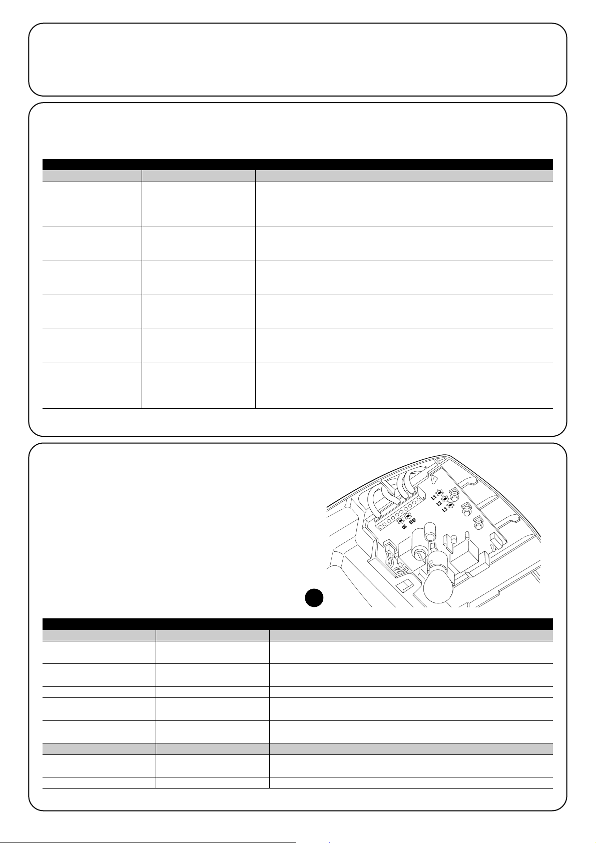
84
Led OK Cause ACTION
Led STOP Cause ACTION
Éteinte
7.7.2) Signalisations sur la logique de commande
Dans la logique de SPIN il y a une série de led qui peuvent donner
chacune des signalisations particulières aussi bien durant le fonctionnement normal qu’en cas d’anomalie.
Tableau 23: led sur les bornes de la logique
Anomalie
Vérifier si l’alimentation arrive; vérifier si les fusibles sont intervenus; si c’est le cas, vérifier la cause de la panne et remplacer les fusibles par des fusibles ayant les mêmes caractéristiques.
Allumée Anomalie grave
Il y a une anomalie grave; essayer d’éteindre la logique pendant quelques secondes; si
la situation persiste, il y a une panne et il faut remplacer la carte électronique.
Un clignotement à la seconde Tout est OK Fonctionnement normal de la logique
2 clignotements rapides
Il y a eu une variation de l’état
des entrées.
C’est normal quand il y a un changement de l’une des entrées: PP, STOP,
intervention des photocellules ou quand on utilise l’émetteur radio.
Série de clignotements séparés
par une pause d’une seconde.
Diverses
C’est la même signalisation que celle du clignotant ou de l’éclairage automatique. Voir le tableau 22.
Éteinte
Intervention de l’entrée de
STOP
Vérifier les dispositifs connectés à l’entrée de STOP.
Allumée Tout est OK Entrée STOP active
44
7.7) Diagnostic et signalisations
Certains dispositifs offrent directement des signalisations particulières à travers lesquelles il est possible de reconnaître l’état de fonctionnement ou l’éventuel problème.
7 clignotements
pause de 1 seconde
7 clignotements
Au début de la manœuvre, une ou plusieurs photocellules refusent d’autoriser
la manœuvre, vérifier s’il y a des obstacles.
Durant le mouvement de fermeture, c'est normal si un obstacle est effectivement présent.
7.7.1) Signalisation avec le clignotant et l’éclairage automatique
Si un clignotant est connecté, durant la manœuvre, il émet un clignotement toutes les secondes; quand des anomalies se produisent, les clignotements sont plus brefs; les clignotements se répètent deux fois, avec un intervalle d’une seconde. On retrouve les mêmes signalisations
de diagnostic sur l’éclairage automatique.
Tableau 22: signalisations sur le clignotant FLASH.
Clignotements rapides Cause ACTION
2 clignotements
pause de 1 seconde
2 clignotements
Intervention d’une
photocellule
3 clignotements
pause de 1 seconde
3 clignotements
Intervention du limiteur
de la « Force moteur »
Durant le mouvement, la porte a rencontré une friction plus forte; en vérifier la
cause.
4 clignotements
pause de 1 seconde
4 clignotements
Intervention de l’entrée de
STOP
Au début de la manœuvre ou durant le mouvement, il y a eu une intervention
de l’entrée de STOP; en vérifier la cause.
5 clignotements
pause de 1 seconde
5 clignotements
Erreur dans les paramètres
internes de la logique
électronique.
Attendre au moins 30 secondes et réessayer d’exécuter une commande; si la
situation persiste, il peut y avoir une panne grave; il faut alors remplacer la carte électronique.
6 clignotements
pause de 1 seconde
6 clignotements
La limite maximum du
nombre de manœuvres à
l’heure a été dépassée.
Attendre quelques minutes que le limiteur de manœuvres retourne sous la
limite maximum.
Erreur dans les circuits
électriques internes
Déconnecter tous les circuits d’alimentation pendant quelques secondes puis
tenter d’exécuter de nouveau une commande; si la situation persiste, il peut y
avoir une panne grave sur la carte ou sur la câblage du moteur. Vérifier et procéder aux remplacements nécessaires.
Page 85

85
F
Led L1 Description
• Programmation des fonctions en cours
• Si elle clignote en même temps que L2, cela signifie qu’il faut effectuer la reconnaissance des positions d’ouverture et de fermeture de la porte (voir paragraphe 4.2 « Reconnaissance des positions d’ouverture et de fermeture de la porte »).
Led L3 Description
Led L2 Description
Éteinte
Tableau 24: led sur les touches de la logique de commande
Correct durant le fonctionnement normal.
Durant le fonctionnement normal, indique qu’a été reçu un code radio qui ne fait pas partie des codes mémorisés.
• Programmation des fonctions en cours.
• Mémorisation ou effacement des émetteurs radio.
Allumée
Clignote
Éteinte Durant le fonctionnement normal, indique « Vitesse moteur » lente.
Durant le fonctionnement normal, indique « Vitesse moteur » rapide.
• Programmation des fonctions en cours
• Si elle clignote en même temps que L3, cela signifie qu’il faut effectuer la reconnaissance des positions d’ouverture et de
fermeture de la porte (voir paragraphe «4.2(4) Reconnaissance des positions d’ouverture et de fermeture de la porte »).
Allumée
Clignote
Éteinte Durant le fonctionnement normal, indique « Fermeture automatique » non active.
Durant le fonctionnement normal, indique « Fermeture automatique » active.Allumée
Clignote
7.8) Accessoires
SPIN peut être équipé des accessoires en option suivants. Consulter le catalogue des produits Nice S.p.A. pour avoir la liste complète et mise à jour des accessoires.
Pour tous
• SPA2 Débrayage mécanique avec cordon métallique. À utiliser
dans les installations qui prévoient comme point d’accès uniquement la porte à automatiser.
Pour tous
• SPA5 Bras oscillant. Il est nécessaire quand la porte à automati-
ser est basculante, à contrepoids comme à ressorts.
Page 86

86
Alimentation de secours Non
Sortie clignotant pour 1 clignotant LUCYB (12 V, 21 W).
Éclairage automatique SPIN
Éclairage automatique SPIN/V1
12 V-21 W douille BA15
12 V-21 W douille BA15
Utilisation en atmosphère particulièrement acide ou saline ou potentiellement explosive
225 x 330 h 100 / 3,3Kg
Dans le but d’améliorer ses produits, Nice S.p.A. se réserve le droit de modifier les caractéristiques techniques à tout moment et sans préavis, en garantissant dans tous les cas le bon fonctionnement et le type d’utilisation prévus.
Toutes les caractéristiques techniques se réfèrent à une température ambiante de 20 °C (± 5 °C).
8) Caractéristiques techniques
Typologie
Caractéristiques techniques
Opérateur électromécanique pour le mouvement automatique de portes de garage à usage résidentiel avec logique électronique de commande incorporée.
Pignon Diamètre 9,5 mm, 28 dents; pour rails SNA11 et rails fournis avec SPIN10KCE.
Modèle type SN6011
Couple maximum au démarrage
[correspondant à la capacité de mettre en
mouvement un portail]
9.9Nm
[550N]
4.95Nm
[275N]
Couple nominal [correspond à la capacité
de développer une force pour maintenir en
mouvement la porte]
Vitesse à vide [correspondant à si est programmée la vitesse « rapide »]
103 rpm
[0,14m/s]
La logique de commande permet de programmer 2 vitesses équivalant à 100% - 60% environ.
Vitesse au couple nominal
[correspondant à si est programmée la
vitesse « Rapide »]
52 rpm
[0,07m/s]
Fréquence maximum des cycles de fonctionnement
30 cycles/jour (la logique limite les cycles au maximum prévu dans les tableaux 3 et 4)
Temps maximum de fonctionnement continu
3 minutes (la logique limite le fonctionnement continu au maximum prévu dans les tableaux
3 et 4)
Limites d’utilisation
Généralement SPIN est en mesure d’automatiser des portes sectionnelles ou basculantes
dont les dimensions sont comprises dans les valeurs indiquées dans le tableau 2 et suivant les limites prévues dans les tableaux 3 et 4.
Puissance maximum absorbée 200W
Classe d’isolement 1 (la mise à la terre est nécessaire)
Entrée STOP
Pour contacts normalement fermés, normalement ouverts ou à résistance constante.
8,2kΩ; en auto-apprentissage (une variation par rapport à l'état mémorisé provoque la
commande STOP)
Entrée PP Pour contacts normalement ouverts (la fermeture du contact provoque la commande P.P.).
Entrée ANTENNE Radio 52 ohms pour câble type RG58 ou similaires.
Récepteur radio incorporé
Alimentation SPIN
Alimentation SPIN/V1
230Vac (±10%) 50/60Hz.
120Vac (±10%) 50/60Hz.
Fonctions programmables 6 fonctions de type ON-OFF et 6 fonctions réglables (voir tableaux 15, 15a et 17, 17a).
Température de fonctionnement -20°C ÷ 50°C
Non
Indice de protection IP 40 (utilisation à l’intérieur ou dans des milieux protégés uniquement)
Dimensions et poids
Fonctions en auto-apprentissage
Fonctions en auto-apprentissage Auto-apprentissage du type de dispositif de « STOP »
(contact NO, NF ou résistance 8,2kΩ). Auto-apprentissage des positions d’ouverture et de
fermeture de la porte et calcul des points de ralentissement et d’ouverture partielle.
Modèle type Rail contenu dans SPIN10KCE SNA11
Typologie profil de 3 segments en acier zingué profil unique en acier zingué
Longueur rail 3,15 m 3,15 m
Hauteur rail 35 mm 35 mm
Course utile 2,6 m 2,6 m
Longueur courroie 6 m 6 m
Hauteur courroie 6 mm 6 mm
Résistance à la traction 730 N 730 N
Caractéristiques techniques des rails
Page 87

87
F
Caractéristiques techniques récepteur radio incorporé
Typologie Récepteur à 4 canaux par radiocommande incorporé
Fréquence 433.92MHz
Codage Numérique à code fixe à 12 bits, type FLO
Numérique à rolling code à 52 bits, type FLOR
Numérique à rolling code à 64 bits, type SMILO
Compatibilité émetteurs (1) FLO, VERY VE
FLOR, VERY VR; seulement pour groupe simple: ERGO, PLANO, PLANOTIME
SMILO
Émetteurs mémorisables Jusqu’à 160 s’ils sont mémorisés en Mode I
Impédance d’entrée 52Ω
Sensibilité supérieure à 0,5 µV
Portée des émetteurs de 100 à 150 m; cette distance peut varier en présence d’obstacles et de parasites
électromagnétiques et elle est influencée par la position de l’antenne réceptrice.
Sorties /
Température de fonctionnement -20°C ÷ 55°C
Note 1: Le premier émetteur activé détermine également la typologie des émetteurs qui pourront être activés ensuite.
Typologie Émetteur à 2 canaux par radiocommande
Fréquence 433.92MHz
Codage Numérique à code fixe à Numérique à rolling code à Numérique à rolling code à
12 bits, type FLO 52 bits, type FLOR 64 bits, type SMILO
Touches 2
Alimentation 12 Vcc avec pile type 23 A
Absorption 25mA
Durée de la pile 1 an, estimée sur une base de 20 commandes/jour d’une durée de 1 s à 20 °C
(à basse température, l’efficacité de la pile diminue).
Puissance irradiée 100µW
Dimensions et poids 72 x 40 h 18mm / 30g 72 x 40 h 18mm / 30g Diamètre 48 h 14 mm / 19 g
Indice de protection IP 40 (utilisation à l’intérieur ou dans des milieux protégés)
Température de fonctionnement -40°C ÷ 85°C
Caractéristiques techniques émetteur: FLO2 émetteur: FLO2R-S émetteur: SM2
Page 88

Page 89

89
F
Nous vous félicitons d’avoir choisi un produit Nice pour
votre automatisation! Nice S.p.A. produit des composants
pour l’automatisation de portails, portes, rideaux métalliques,
volets roulants et stores: opérateurs, logiques de commande,
radiocommandes, clignotants, photocellules et accessoires.
Nice n’utilise que des matériaux et des usinages de qualité et
par vocation, elle recherche des solutions innovantes qui simplifient au maximum l’utilisation de ses appareils, très soignés
sur le plan de la technique, de l’esthétique et de l’ergonomie:
dans la vaste gamme Nice, votre installateur aura choisi sans
aucun doute le produit le plus adapté à vos exigences. Nice
n’est toutefois pas le producteur de votre automatisme qui est
en effet le résultat d’un travail d’analyse, évaluation, choix des
matériaux et réalisation de l’installation, exécuté par votre installateur de confiance. Chaque automatisme est unique et seul
votre installateur possède l’expérience et la compétence professionnelle nécessaires pour réaliser une installation répondant à vos exigences, sûre et fiable dans le temps et surtout,
exécutée dans les règles de l’art et conforme par conséquent
aux normes en vigueur. Une installation d’automatisation est
une belle commodité ainsi qu’un système de sécurité valable;
avec quelques attentions très simples, elle est destinée à durer
dans le temps. Même si l’automatisme en votre possession
satisfait le niveau de sécurité requis par les normes, cela n’exclut pas la persistance d’un «risque résiduel», c’est-à-dire la
possibilité de situations de danger dues généralement à une
utilisation inconsciente, voire erronée. C’est la raison pour
laquelle nous désirons vous donner quelques conseils sur les
comportements à adopter pour éviter tout inconvénient:
• Avant d’utiliser pour la première fois l’automatis-
me, faites-vous expliquer par l’installateur l’origine des
risques résiduels et consacrez quelques minutes à la lecture du guide «Instructions et avertissements pour
l’utilisateur» qui vous est remis par l’installateur. Conservez le guide pour pouvoir le consulter dans le futur, en cas
de doute, et remettez-le, le cas échéant, au nouveau propriétaire de l’automatisme.
• Les photocellules ne sont pas un dispositif de
sécurité mais uniquement un dispositif auxiliaire
de sécurité. Elles sont construites selon une technologie
extrêmement fiable mais peuvent, dans des situations
extrêmes, connaître des problèmes de fonctionnement ou
même tomber en panne; dans certains cas, la panne peut
ne pas être immédiatement évidente.
C’est pourquoi il est conseillé dans tous les cas ce qui suit:
- Le transit n’est autorisé que si le portail ou la porte sont
complètement ouverts et avec les vantaux ou le tablier
immobiles.
- IL EST ABSOLUMENT INTERDIT de transiter pendant que
le portail ou la porte sont en phase de fermeture!
Vérifier régulièrement le fonctionnement correct des photocellules et faire exécuter les contrôles de maintenance prévus, au minimum tous les 6 mois.
• Votre automatisme est un équipement qui exécute
fidèlement vos commandes; une utilisation inconsciente et incorrecte peut le rendre dangereux: ne commandez
pas le mouvement de l’automatisme si des personnes, des
animaux ou des objets se trouvent dans son rayon d’action.
• Enfants: une installation d’automatisation garantit un
degré de sécurité élevé en empêchant avec ses systèmes
de détection le mouvement en présence de personnes ou
d’objets et en garantissant une activation toujours prévisible
et sûre. Il est toutefois prudent de ne pas laisser jouer les
enfants à proximité de l’automatisme et, pour éviter les activations involontaires, de ne pas laisser à leur portée les
émetteurs qui commandent la manœuvre: ce n’est pas
un jeu!
• Contrôler souvent l'installation, en particulier les
câbles, les ressorts et les supports pour déceler les éventuels déséquilibrages, signes d’usure ou dommages. Vérifier
chaque mois que la motorisation inverse le mouvement
quand la porte rencontre un objet de 50 mm de haut posé
sur le sol. Ne pas utiliser l'automatisme si une réparation ou
un réglage est nécessaire car une panne de l'installation ou
une porte mal équilibrée peut causer des blessures.
• Anomalies: si vous notez une anomalie quelconque dans
le fonctionnement de l’automatisme, mettez l’installation
hors tension et effectuez un débrayage manuel; Ne tentez
jamais de le réparer vous-même mais demandez l’intervention de votre installateur de confiance: dans l’intervalle, l’installation peut fonctionner comme un système non automatisé, après avoir débrayé l’opérateur suivant les indications
fournies plus loin.
• Maintenance: comme toutes les machines, votre automatisme a besoin d’une maintenance périodique pour pouvoir
fonctionner le plus longtemps possible et en toute sécurité.
Établissez avec votre installateur un plan de maintenance
périodique programmée; Nice conseille une intervention tous
les 6 mois pour une utilisation domestique normale mais cette période peut varier en fonction de l’intensité d’utilisation.
Toute intervention de contrôle, maintenance ou réparation
doit être exécutée exclusivement par du personnel qualifié.
• Même si vous estimez en être capable, ne modifiez pas
l’installation et les paramètres de programmation et de
réglage de l’automatisme: la responsabilité en incombe à
votre installateur.
• L’essai de fonctionnement, les opérations de maintenance
périodique et les éventuelles réparations doivent être documentés par la personne qui s’en charge et les documents
doivent être conservés par le propriétaire de l’installation.
Les seules interventions que l’utilisateur peut et doit
effectuer périodiquement sont le nettoyage des verres des
photocellules et l’élimination des feuilles et des cailloux qui
pourraient bloquer l’automatisme. Pour empêcher que quelqu’un puisse actionner la porte, avant d’intervenir, n’oubliez
pas de débrayer l’automatisme (comme cela est décrit
plus loin), de débrancher toutes les sources d’ali-
mentation (y compris les batteries tampon si elles sont
présentes) et d’utiliser pour le nettoyage uniquement un
chiffon légèrement imbibé d’eau.
• Mise au rebut: à la fin de la vie utile de l’automatisme,
assurez-vous que le démantèlement est effectué par du
personnel qualifié et que les matériaux sont recyclés ou mis
au rebut en respectant les normes locales en vigueur.
• En cas de ruptures ou de coupure de courant: en
attendant l’intervention de votre installateur (ou le retour du
courant si l’installation n’est pas équipée d’une batterie tampon), l’installation peut être actionnée comme n’importe
quel autre système non automatisé. Pour cela, il faut effectuer le débrayage manuel: cette opération a fait l’objet d’une
étude particulière de la part de Nice pour vous assurer une
utilisation toujours extrêmement simple, sans aucun outil ni
effort physique.
Instructions et recommandations destinées à l’utilisateur de l’opérateur SPIN
Consignes importantes de sécurité
Pour la sécurité des personnes, il est important de respecter ces consignes.
Conserver ces consignes.
Ces instructions peuvent compléter les « Instructions et recommandations pour l’utilisation » que l’installateur doit remettre au propriétaire de l’automatisme et doivent dans tous les cas être complétées par celles-ci.
!
Page 90

90
Débrayage et mouvement manuel: avant d’effectuer cette opération, faire attention au fait que le débrayage ne
peut être fait que lorsque la porte est à l’arrêt.
1. Tirer le cordon de débrayage vers le bas jusqu'à sentir le décrochage du chariot.
2. Il est maintenant possible d’agir manuellement sur la porte
3. Pour rétablir le fonctionnement de l’automatisme, remettre la porte dans sa position initiale, jusqu'à sentir l’accro-
chage du chariot.
Commande avec sécurités hors service: Si les dispositifs de sécurité ne fonctionnent pas correctement ou sont
hors service, on peut quand même commander la porte.
• Actionner la commande de la porte (avec la télécommande, le sélecteur à clé, etc.); si tout est en ordre, la
porte s’ouvre ou se ferme normalement, sinon le clignotant émet quelques clignotements mais la manœuvre ne
démarre pas (le nombre de clignotements dépend du
motif pour lequel la manœuvre ne démarre pas).
• Maintenant, dans les 3 secondes, il faut actionner de
nouveau la commande et la maintenir active.
• Au bout d’environ 2 s le mouvement de la porte commencera en mode « homme mort », c’est-à-dire que
tant que la commande est maintenue, le portail continue sa manœuvre; dès que la commande est relâchée,
la porte s’arrête.
Avec les dispositifs de sécurité hors service, il
faut faire réparer au plus tôt l’automatisme.
Remplacement de la pile de l’émetteur: si votre ins-
tallation est munie d’une radiocommande qui au bout
d’une certaine période présente des problèmes de fonctionnement ou ne fonctionne plus du tout, cela pourrait
dépendre tout simplement du fait que la pile est usagée
(suivant l’intensité d’utilisation, il peut s’écouler plusieurs
mois jusqu’à plus d’un an). Vous pouvez vérifier cet état
de chose si le voyant de confirmation de la transmission
est faible, s’il ne s’allume plus du tout ou s’il ne s’allume
qu’un bref instant. Avant de vous adresser à l’installateur,
essayez de remplacer la pile en utilisant celle d’un autre
émetteur qui fonctionne encore: si cette intervention remédie au problème, il vous suffit de remplacer la pile usagée
par une neuve du même type.
Attention: les piles contiennent des substances polluantes: ne pas les jeter à la poubelle mais suivre les règles
de tri sélectif prévues par les réglementations locales.
1. Ouvrir le couvercle blanc en appuyant et en le faisant
tourner.
2. Enlever l’ampoule en appuyant vers le haut puis en
la faisant tourner. Mettre une ampoule neuve de 12
V / 21 W douille BA15.
Remplacement de l’ampoule: avant d’effectuer cette opération, couper l’alimentation du SPIN.
Êtes-vous satisfait? Si vous désirez équiper votre maison d’un nouvel automatisme, adressez-vous au même ins-
tallateur et à Nice. Vous serez sûr de bénéficier ainsi, en plus du conseil d’un spécialiste et des produits les plus évolués du marché, également du meilleur fonctionnement et de la compatibilité parfaite des différents automatismes installés. Nous vous remercions d’avoir lu ces recommandations et nous espérons que votre nouvelle installation vous
donnera entière satisfaction: pour tout besoin présent ou futur, adressez-vous en toute confiance à votre installateur.
Page 91

Page 92

92
Spin10KCE
Spin11KCE
Inhaltsverzeichnis S.
1 Hinweise 93
2 Produktbeschreibung 93
2.1 Einsatzgrenzen 94
2.2 Typische Anlage 95
2.3 Kabelliste 95
3 Installation 96
3.1 Vorprüfungen 96
3.2 Befestigung von SPIN 96
3.2.1 Zusammenbau der mit SPIN10KCE gelieferten
Führung 97
3.2.2 Zusammenbau der Führung SNA11 98
3.2.3 Befestigung des Toröffners an der Führung 98
3.2.4 Befestigung des Toröffners an der Decke 98
3.3 Installation der verschiedenen Vorrichtungen 99
3.4 Elektrische Anschlüsse 100
3.5 Beschreibung der elektrischen Anschlüsse 101
4 Endprüfungen und Anlassen 101
4.1 Anschluss der Versorgung 101
4.2 Erlernung der Öffnungs- und Schließpositionen
des Tors 102
4.3 Überprüfung der Torbewegung 102
4.4 Bereits programmierte Funktionen 102
4.5 Funkempfänger 102
4.5.1 Speicherung der Sender 103
4.5.2 Speicherung im Modus I 103
4.5.3 Speicherung im Modus II 103
4.5.4 Fernspeicherung 104
4.5.5 Löschen der Funksender 104
5 Abnahme und Inbetriebsetzung 104
5.1 Abnahme 104
5.2 Inbetriebsetzung 105
6 Wartung und Entsorgung 105
6.1 Wartung 105
6.2 Entsorgung 105
7 Weitere Auskünfte 106
7.1 Programmierungstasten 106
7.2 Programmierungen 106
7.2.1 Funktionen des ersten Niveaus 106
(ON-OFF-Funktionen)
7.2.2 Erstes Niveau – Programmierungen
(ON-OFF-Funktionen) 107
7.2.3 Funktionen des zweiten Niveaus
(einstellbare Parameter) 108
7.2.4 Zweites Niveau: Programmierungen
(einstellbare Parameter) 108
7.2.5 Erstes Niveau - Programmierungsbeispiel
(ON-OFF-Funktionen) 109
7.2.6 Zweites Niveau: Programmierungsbeispiel
(einstellbare Parameter) 110
7.3 Hinzufügen oder Entfernen von Vorrichtungen 111
7.3.1 Eingang STOPP 111
7.3.2 Photozellen 112
7.3.3 Elektroschloss 112
7.4 Sonderfunktionen 113
7.4.1 Funktion “Öffnet Immer” 113
7.4.2 Funktion “Todmann” 113
7.5 Verbindung sonstiger Vorrichtungen 113
7.6 Probleme und deren Lösungen 113
7.7 Diagnose und Anzeigen 114
7.7.1 Anzeigen durch die Blinkleuchte und
die zusätzliche Beleuchtung 114
7.7.2 Anzeigen durch die Steuerung 114
7.8 Zubehör 115
8 Technische Merkmale 116
Anweisungen und Hinweise für den Benutzer des
Toröffners SPIN 119
Page 93
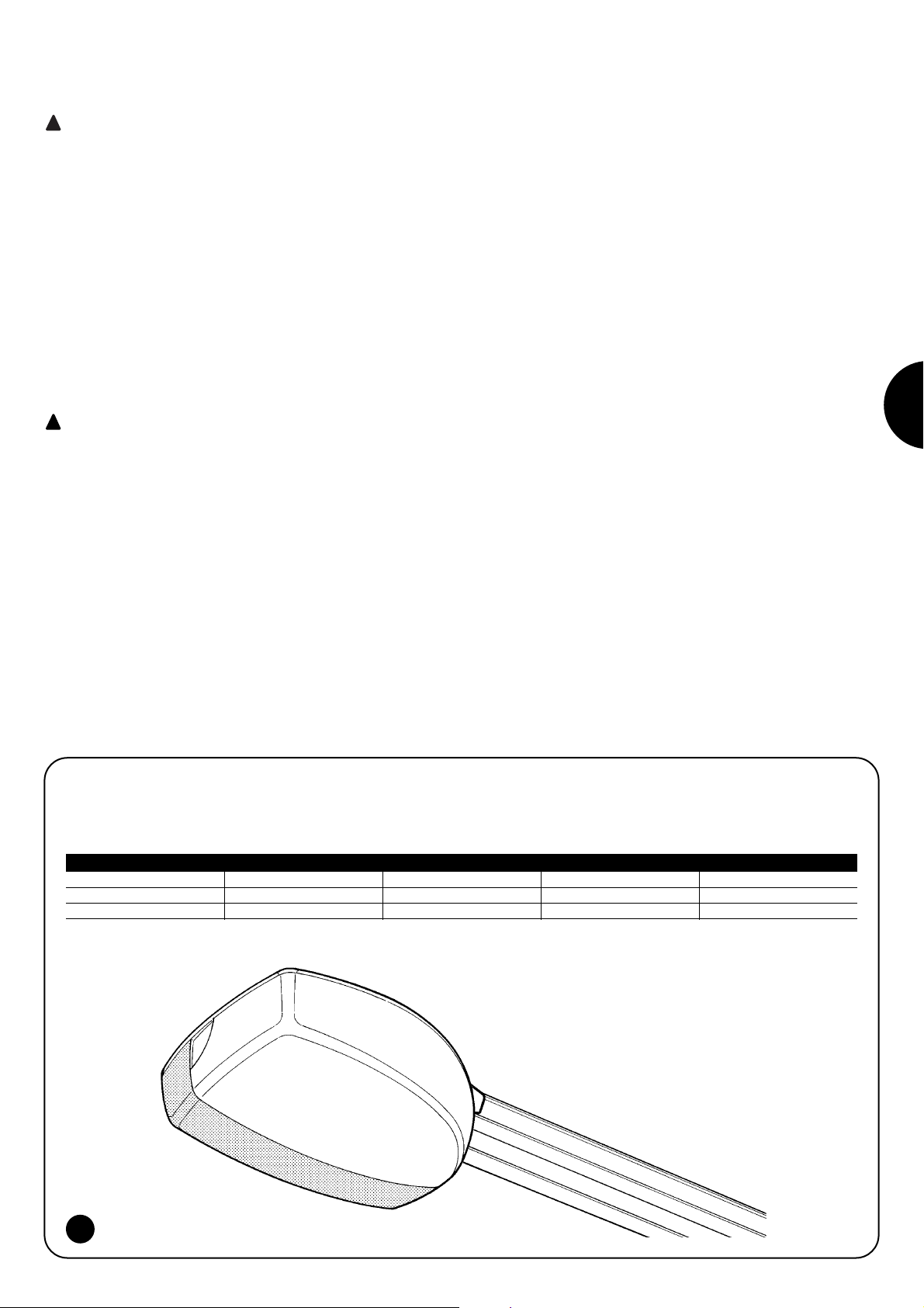
93
D
SPIN ist eine Toröffnerlinie für die Automatisierung von Sektionaltoren und, mit dem nicht mitgelieferten Spezialzubehör SPA5 auch für
die Automatisierung von Schwingtoren mit Federn oder Gegengewichten, die ausfahrend oder nicht sein können.
SPIN funktioniert mit elektrischer Energie; bei Stromausfall kann der
Toröffner entriegelt und das Tor von Hand bewegt werden.
Zur Linie SPIN gehören die in Tabelle 1 beschriebenen Produkte.
* siehe Paragraph “4.5 Funkempfänger”, was die einsetzbaren Sendertypen betrifft.
1) Hinweise
Wichtige Sicherheitsanweisungen für die Installation
Eine unkorrekte Installation kann schwere Schäden verursachen.
Alle Installationsanweisungen befolgen.
Die vorliegenden Anweisungen enthalten wichtige Sicherheitsinformationen für die Installation; vor der Installation alle Anweisungen lesen. Dieses Handbuch auch für die Zukunft sorgfältig aufbewahren.
Wenn in den vorliegenden Anweisungen Daten, Hinweise und sonstiges
angegeben wird, das für alle Produkte gilt, wird der Name der Produktlinie
“SPIN” verwendet. Die Beschreibung der einzelnen Produkte befindet sich
in Kapitel “2 Produktbeschreibung”. Unter Berücksichtigung der Gefahren,
die bei Installation und Bedienung von SPIN auftreten können, muss die
Installation für größte Sicherheit unter voller Einhaltung von Gesetzen, Vorschriften und Verordnungen erfolgen. In diesem Kapitel sind Hinweise allgemeiner Art gegeben; weitere wichtige Hinweise befinden sich in den
Kapiteln “3.1 Vorprüfungen”; “5 Abnahme und Inbetriebsetzung”.
Nach der neuesten europäischen Gesetzgebung, gehört
die Realisierung einer automatischen Tür oder eines automatischen Tors zu den Verordnungen der Richtlinie 98/37/CE
(Maschinenrichtlinie) und insbesondere zu den Vorschriften:
EN 12445; EN 12453 und EN 12635, die es erlauben, die vermutliche Konformität zu erklären.
Weitere Auskünfte und Hinweise zur Analyse der Risiken und der Realisierung der Technischen Unterlagen stehen in www.niceforyou.com zur
Verfügung.
• Die vorliegende Anleitung ist nur für technisches Personal bestimmt,
das für die Installation qualifiziert ist. Mit Ausnahme der Anlage “Anweisungen und Hinweise für den Benutzer des Toröffners SPIN“, die der
Installateur abtrennen muss, ist keine im vorliegenden Heft enthaltene
Information als interessant für den Endbenutzer zu betrachten!
• Ein Gebrauch von SPIN, der anders als in diesen Anweisungen vorgesehen ist, ist verboten; ein unsachgemäßer Gebrauch kann Gefahren
und Personen- oder Sachschäden verursachen.
• Vor der Installation ist die Risikoanalyse auszuführen, welche die Liste
der wesentlichen Sicherheitsanforderungen, vorgesehen in Anlage I
der Maschinenrichtlinie einschließt und die jeweiligen, angewendeten
Lösungen angeben muss. Es wird daran erinnert, dass die Risikoanalyse eine der Unterlagen ist, die Bestandteil der “Technischen Dokumentation“ der Automatisierung sind.
• Je nach Einsatzbedingungen und vorhandenen Gefahren prüfen, ob
weitere Vorrichtungen und Materialien erforderlich sind, um die Automatisierung mit SPIN zu vervollständigen; berücksichtigt werden müssen zum Beispiel Aufprallgefahr, Quetsch- und Mitnehmgefahr usw.
und sonstige Gefahren allgemein.
• Keine Änderungen an keinem Teil ausführen, falls nicht im vorliegenden
Handbuch vorgesehen. Vorgänge dieser Art können nur Betriebsstörungen verursachen. NICE lehnt jegliche Haftung für Schäden aufgrund geänderter Produkte ab.
• Während Installation und Gebrauch vermeiden, dass Festteile oder Flüssigkeiten in die Steuerung und sonstige geöffnete Vorrichtungen eindringen können; wenden Sie sich ggf. an den NICE Kundendienst; der
Gebrauch von SPIN in solchen Situationen kann Gefahren verursachen.
• Der Automatismus darf erst verwendet werden, nachdem die Inbetriebsetzung ausgeführt wurde, wie in Punkt “5 Abnahme und Inbetriebsetzung“ vorgesehen.
• Das Verpackungsmaterial von SPIN muss unter voller Einhaltung der
örtlichen Vorschriften entsorgt werden.
• Wenn ein Defekt mit den im vorliegenden Handbuch gegebenen Infos
nicht beseitigt werden kann, wenden Sie sich bitte an den NICE Kundendienst.
• Wenn Automatikschalter oder Sicherungen ausgelöst werden, muss
vor ihrer Rückstellung der Defekt festgestellt und beseitigt werden.
• Vor dem Zugriff auf die Klemmen im Deckel von SPIN, alle Kreisläufe der
Versorgung abtrennen; falls die Abtrennvorrichtung nicht sichtbar ist, ein
Schild mit der Aufschrift: “ACHTUNG – WARTUNG IM GANG” anbringen.
!
!
2) Produktbeschreibung
1
Modell Typ Toröffner Führung Funkempfänger Funksender
SPIN10KCE SN6011 3x1m Eingebaut FLO2R-S*
SPIN11KCE SN6011 3m Eingebaut FLO2R-S*
Tabelle 1: Beschreibung der Bestandteile von SPIN
Page 94

94
2.1) Einsatzgrenzen
Die Leistungsdaten der Produkte der Linie SPIN sind in Kapitel “8 Technische Merkmale” angegeben; sie sind die einzigen Werte, die eine
korrekte Bewertung der Eignung ermöglichen.
Aufgrund ihrer strukturellen Merkmale sind die Produkte der Linie SPIN für den Einsatz an Sektional- oder Schwingtoren gemäß den in Tabelle 2, 3 und 4 angegebenen Grenzen geeignet.
Die Maße in Tabelle 2 dienen nur als Hinweis für eine generelle Schätzung. Ob SPIN effektiv zur Automatisierung eines bestimmten Tors geeignet ist, hängt vom Gleichgewicht des Torflügels, von der Reibung der Führungen und sonstigen, auch gelegentlichen Vorfällen ab, wie Windstärke oder Vorhandensein von Eis, das die Bewegung des Torflügels behindern könnte.
Für eine effektive Überprüfung muss die Kraft gemessen werden, die zur Bewegung des Torflügels auf seiner ganzen Laufstrecke erforderlich ist, dann prüfen, dass diese das in Kapitel “8 Technische Merkmale” angegebene Nenndrehmoment nicht überschreitet; um die Anzahl
an Zyklen/Stunde und die der Zyklen nacheinander zu bestimmen, ist das in den Tabellen 3 und 4 angegebene zu berücksichtigen.
Mit der Torhöhe kann die Höchstzahl an Zyklen pro Stunde und die Höchstzahl der Zyklen nacheinander bestimmt werden, wogegen mit der
zur Torflügelbewegung notwendigen Kraft der Reduzierungsanteil der Zyklen in Prozenten bestimmt werden kann. Wenn der Torflügel zum
Beispiel 2,2 m hoch ist, wären 12 Zyklen/Stunde und 6 Zyklen nacheinander möglich, wenn aber zur Bewegung des Torflügels 250N notwendig sind, müssen die Zyklen auf 70% reduziert werden; das Ergebnis ist daher 8 Zyklen/Stunde und ca. 4 Zyklen nacheinander.
Um Überhitzungen zu vermeiden, sieht die Steuerung einen Begrenzer vor, der sich auf die Beanspruchung des Motors und die Dauer der
Zyklen beruht und bei Überschreitung der Höchstgrenze eingreift.
Anmerkung: 1Kg = 9.81N, daher, zum Beispiel, 500N = 51Kg
Torhöhe Meter max. Zyklen/Stunde max. Zyklen nacheinander
Fino a 2 16 8
2÷2,5 12 6
2,5÷3 10 5
3÷3,5 8 4
Tabelle 3: Grenzwerte in Abhängigkeit von der Torhöhe
Kraft für die Bewegung des Torflügels N Reduzierung der Zyklen (in Prozenten)
bis zu 200 100%
200÷300 70%
300÷400 25
Tabelle 4: Grenzwerte in Abhängigkeit von der Kraft, die zur Bewegung des Torflügels notwendig ist
Modell Typ: SEKTIONALTOR nicht vorspringendes SCHWINGTOR Vorspringendes SCHWINGTOR
(mit Zubehör SPA5) (mit Zubehör SPA5) oder mit Federn (ohne SPA5)
Höhe Breite Höhe Breite Höhe Breite
SPIN10KCE 2.4m 3.7m 2.2m 3.5m 2.8m 3.5m
SPIN11KCE 2.4m 3.7m 2.2m 3.5m 2.8m 3.5m
Tabelle 2: Einsatzgrenzen der Toröffner SPIN
Page 95

95
D
2.2) Typische Anlage
In Abbildung 2 ist eine typische Installation für ein Sektionaltor gezeigt.
2
1 SPIN
2 Photozellen
3 Photozellen auf Standsäule (abb. 3)
4 Hauptschaltleiste
5 Blinkleuchte mit eingebauter
Antenne
6 Schlüsseltaster
7 Funksender
Die Abbildungen 3 und 4 zeigen typische Installationsbeispiele für ein ausfahrendes und ein nicht ausfahrendes Schwingtor.
Für die Installation an Schwingtoren ist das Zubehör SPA5 erforderlich.
!
3 4
5
6
C
B
A
2
2
4
B
B
D
7
1
3
2.3) Kabelliste
In Abbildung 3 Typische Anlage sind die Kabel für den Anschluss der
verschiedenen Vorrichtungen angegeben; in Tabelle 5 sind die Merkmale der Kabel verzeichnet.
Die benutzten Kabel müssen für den Installationstyp
geeignet sein; zum Beispiel wird ein Kabel des Typs
H03VV-F für das Verlegen in Innenräumen empfohlen.
!
Anmerkung 1: die beiden Kabel 2x0,5mm2können mit nur einem Kabel 4x0,5mm2ersetzt werden.
Anmerkung 2: für den Anschluss der Schaltleisten an Toren müssen spezielle Vorrichtungen verwendet werden, die eine Verbindung auch
bei sich bewegendem Tor ermöglichen.
Anschluss Kabeltyp Zulässige Höchstlänge
A: Blinkleuchte mit Antenne Nr. 1 Kabel 2x0,5mm
2
20m
Nr. 1 Abschirmkabel Typ RG58 20m (besser, wenn unter 5m)
B: Photozellen Nr. 1 Kabel 2x0,25mm2per TX 30m
Nr. 1 Kabel 4x0,25mm2per RX 30m
C: Schlüsseltaster Nr. 2 Kabel 2x0,5mm2(Anmerkung 1) 50m
D: Hauptschaltleiste Nr. 1 Kabel 2x0,5mm2(Anmerkung 2) 30m
Tabelle 5: Kabelliste
B
Page 96

96
3.1) Vorprüfungen
Vor der Installation von SPIN sind folgende Kontrollen auszuführen:
• Nach der Installation überprüfen und sicherstellen, dass keine Tor-
teile Platz auf öffentlichen Straßen und Gehsteigen einnehmen.
• Prüfen, dass sich das gesamte benutzte Material in bestem
Zustand befindet, für den Einsatzzweck geeignet und konform mit
den Vorschriften ist.
• Prüfen, dass sich die Struktur des Tors zu einer Automatisierung
eignet.
• Prüfen, dass sich Motorkraft und Abmessungen des Torflügels inner-
halb der Einsatzgrenzen in Kapitel “2.1 Einsatzgrenzen” befinden.
• Durch Vergleich mit den Werten in Kapitel “8 Technische Merkma-
le” prüfen, dass die statische Reibung (bzw. die zur Bewegung des
Torflügels notwendige Kraft) kleiner als die Hälfte des “maximalen
Drehmoments“ ist, und dass die dynamische Reibung (bzw. die
Kraft, die notwendig ist, um den Torflügel in Bewegung zu halten)
kleiner als die Hälfte des “Nenndrehmoments” ist; eine Spanne der
Kräfte von 50% wird empfohlen, da schlechte Witterung die Reibungswerte erhöhen kann.
• Prüfen, dass entlang dem gesamten Lauf des Tors sowohl in
Schließung als auch in Öffnung keine größeren Reibungen vorhanden sind.
• Die Robustheit der mechanischen Anschläge kontrollieren und
prüfen, dass das Tor nicht aus seinen Führungen gleiten kann.
• Das Gleichgewicht des Tors überprüfen; es darf sich nicht bewe-
gen, wenn es in beliebiger Stellung steht.
• Prüfen, dass die verschiedenen Vorrichtungen in stoßgeschützten
Zonen und auf ausreichend festen Oberflächen befestigt sind.
• Prüfen, dass die minimalen und maximalen Freiräume vorhanden
sind, wie in den Abb. 5 und 6 angegeben.
• Die manuelle Entriegelung in einer Höhe unter 1,8 m anbringen
und dies überprüfen.
• Die Bestandteile des Automatismus dürfen nicht in Wasser oder
andere Flüssigkeiten getaucht werden.
• Die Bestandteile von SPIN nicht in der Nähe von Wärmequellen
oder Flammen halten; dies kann Schäden und Betriebsstörungen
an SPIN sowie Gefahren und Brand verursachen.
• Sollte eine Fußgängertür im Tor oder eine Tür im Bewegungsbe-
reich des Tors vorhanden sein, ist sicher zu stellen, dass sie den
normalen Torlauf nicht behindert; ggf. für ein geeignetes Verblockungssystem sorgen.
• Falls es sich bei dem Tor, das automatisiert werden soll, um ein
Schwingtor handelt, das Maß E in Abbildung 7, bzw. den Mindestabstand zwischen oberer Führungsseite und von der oberen Torkante erreichter Höchststelle überprüfen. Andernfalls kann SPIN
nicht montiert werden.
• Den Stromstecker von SPIN an einer Steckdose mit Sicherheitser-
dung anschließen.
• Der Stecker muss durch eine geeignete magnetothermische Vor-
richtung und durch Differentialschalter geschützt sein.
7
3.2) Befestigung von SPIN
Die Befestigung von SPIN erfolgt in drei Schritten:
• Zusammenbau der Führung (siehe Par. 3.2.1 für die mit
SPIN10KCE gelieferte Führung, Par. 3.2.2 für die Führung SNA11)
• Befestigung des Toröffners an der Führung (siehe Par. 3.2.3)
• Befestigung des Toröffners an der Decke (siehe Par. 3.2.4)
Die Installation von SPIN darf nur von qualifiziertem Personal unter Einhaltung der Gesetze, Vorschriften und Verordnungen sowie der vorliegenden Anweisungen ausgeführt
werden.
!
3) Installation
5
6
200mm
300mm
380mm
E 65÷300 mm
C 2970mm D 380mm
B 0÷400mm
A 40÷400mm
200mm
Page 97
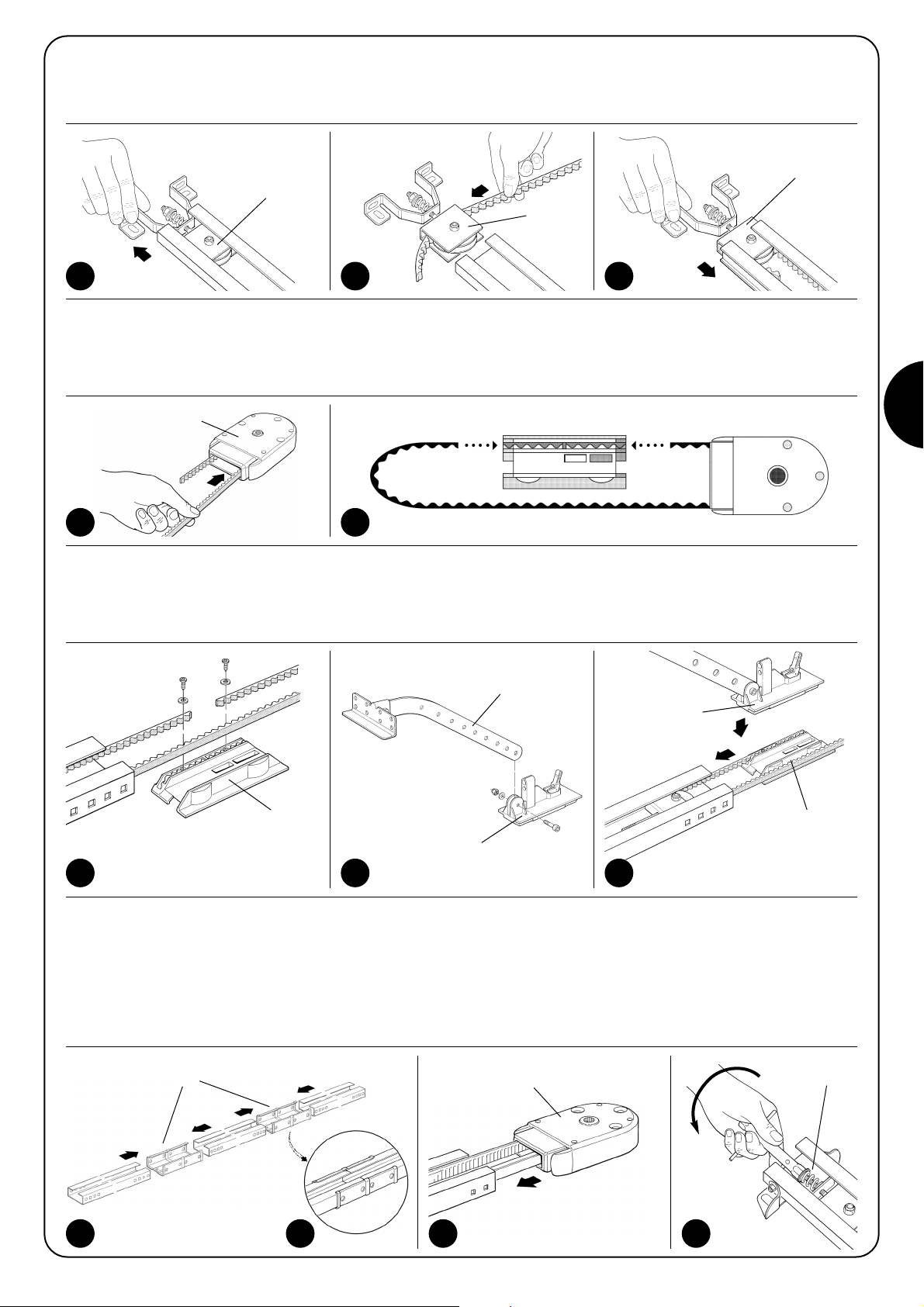
97
D
B
3.2.1) Zusammenbau der mit SPIN10KCE gelieferten Führung
Die mit SPIN10KCE gelieferte Führung muss wie folgend zusammengebaut werden:
1. Unter Bezugnahme auf Abbildung 8, den Riemenspanner (8a) herausnehmen; ein Ende des Riemens in die Scheibe (8b) stecken; den
Riemenspanner wieder in der Führung (8c) anbringen.
4. Beide Riemenenden in den geformten Schlitzen des unteren Wagens (C) anbringen, so dass die Schlitze ganz ausgefüllt sind. Die Rie-
menenden mit den 2 Schrauben V4.2x9.5 und den 2 Unterlegscheiben R05 befestigen - siehe Abbildung 11.
5. Den Zugbügel (D) mit jeweiligen Mutter M6 am siehe Abbildung 12.
6. Den oberen Wagen (E) am unteren (C) einspannen und den ganzen Wagen in die Führung bringen - siehe Abbildung 13.
7. Die drei Führungsteile mit Hilfe eines Hammers fest in die beiden Verbindungsbügel (F) einspannen – siehe die Abbildungen 14 und 15.
Wichtig: Die Führungen müssen in den Bügeln gleiten, bis man ein trockenes Einrastgeräusch hört.
8. Den Riemen sehr genau in der Führung anbringen - er darf nicht verdreht sein.
9. Den Kopf (B) fest in das freie einspannen - siehe Abbildung 16
10.Abschließend, den Riemen mit der Riemenspanner- Stellschraube (H) spannen - siehe Abbildung 17.
Achtung: wenn der Riemen SEHR gespannt ist, könnte das den Antrieb beschädigen; wenn er dagegen WENIG gespannt ist, kann das
unangenehme Geräusche verursachen.
11 12 13
C
14 16 17
H
D
E
E
C
8A 8B 8C
10
A
B
9
A
A
2. Dasselbe Riemenende durch den Kopf (B) führen - siehe Abbildung 9.
Wichtig: Die Position des Riemens beachten: die Zahnung muss nach innen gerichtet sein und der Riemen muss gerade und darf nicht
verdreht sein.
3. Den unteren Wagenteil so ausrichten, dass die Rillen mit den beiden Riemenenden zusammentreffen - siehe Abbildung 10.
F
15
Page 98

98
3.2.2) Zusammenbau der Führung SNA11
Die Führung SNA11 wird vormontiert geliefert. Die einzige Arbeit, die
getan werden muss, ist den Riemen mit der Mutter M8 (H) zu spannen – siehe Abb. 17 – bis er genügend gespannt ist.
3.2.3) Befestigung des Toröffners an der Führung
1. Den Toröffner SPIN mit dem Kopfteil der Führung (B) vereinen; dann diesen mit den 4 Schrauben V6.3x38 befestigen - siehe Abbildung 18.
2. Der Motor kann in drei verschiedene Stellungen gedreht werden, gemäß Abbildung 19.
18 19
3.2.4) Befestigung des Toröffners an der Decke
1. Unter Einhaltung der Maße A und B in Abbildung 5, in der Mitte des Tors die beiden Stellen zur Befestigung des vorderen Führungsbü-
gels aufzeichnen. Je nach Material kann der vordere Bügel mit Nieten, Dübeln oder Schrauben befestigt werden (Abbildungen 20, 21).
Falls es die Maße A und B ermöglichen (Abbildung 5), kann der Bügel gemäß Abbildung 22 direkt an der Decke befestigt werden.
2. Nachdem die Bohrungen an den vorgesehenen Stellen ausgeführt sind, den Toröffner auf dem Boden lassen, die Führung vorne heben
und je nach Material der Oberfläche mit zwei Schrauben, Dübeln oder Nieten befestigen.
3. Die Bügel (I) mit den Schrauben M6x15 (L) und den Muttern M6 (M) befestigen, hierbei die Bohrung auswählen, mit der das Maß B am
genauesten eingehalten werden kann – siehe Abbildung 23.
4. Eine Leiter benutzen und den Toröffner heben, bis die Bügel an der Decke anliegen. Die Stellen aufzeichnen, an denen gebohrt werden
soll, dann den Toröffner wieder auf den Boden legen - siehe Abbildung 24.
20 21 22
23 24
L
M
I
B
Page 99

99
D
5. Die Bohrungen an den aufgezeichneten Stellen ausführen, dann die Bügel mit Hilfe einer Leiter an den soeben ausgeführten Bohrungen
anliegen lassen und mit für das Material geeigneten Schrauben und Dübeln befestigen – siehe Abbildung 25.
6. Prüfen, dass die Führung einwandfrei waagerecht ist, dann den überschüssigen Bügelteil absägen - siehe Abbildung 26.
7. Mit geschlossenem Tor das Seil ziehen, um den Wagen (E) auszuspannen - siehe Abbildung 27.
8. Den Wagen gleiten lassen, bis sich der Toranschlussbügel (D) an der oberen Torkante befindet, genau rechtwinklig zur Führung (G). Dann
den Toranschlussbügel (D) mit Nieten oder Schrauben befestigen - siehe Abbildung 28. Für das Material des Torflügels geeignete Schrauben oder Nieten verwenden und prüfen, dass diese der gesamten Beanspruchung standhalten, die zum Öffnen und Schließen des Torflügels aufgewendet wird.
9. Die Schrauben der beiden mechanischen Endanschläge lockern, dann den vorderen mechanischen Endanschlag (O) so verschieben,
dass er sich vor dem Wagen befindet – siehe Abbildung 29. Den Wagen kräftig in Schließrichtung schieben und die Schraube (N) in der
erreichten Stellung fest anziehen.
10.Das Tor bis zum gewünschten Öffnungspunkt von Hand öffnen, den hinteren mechanischen Endanschlag (Q) so verschieben, dass er
sich neben dem Wagen befindet – siehe Abbildung 30 – und diesen durch kräftiges Anziehen der Schraube (P) blockieren.
11.Versuchen, das Tor von Hand zu bewegen. Prüfen, ob der Wagen leicht und reibungslos auf der Führung gleitet und ob die Bewegung
von Hand leicht und ohne besondere Anstrengungen erfolgt.
25 26
27 28
29 30
E
G
D
O
N
Q
P
3.3) Installation der verschiedenen Vorrichtungen
Alle Vorrichtungen nach den jeweiligen Anweisungen installieren. In
Punkt “3.5 Beschreibung der elektrischen Anschlüsse” und in Abbildung 2 die Vorrichtungen überprüfen, die an SPIN angeschlossen
werden können.
Page 100

100
3.4) Elektrische Anschlüsse
Alle elektrischen Anschlüsse müssen ohne Spannung
zur Anlage ausgeführt werden.
1. Um den Schutzdeckel zu öffnen und Zugang zur elektronischen
Steuerung von SPIN zu erhalten, muss seitlich auf diesen
gedrückt werden, dann den Deckel drehen – siehe Abbildung 31..
2. Die Verbindungskabel zu den anderen Vorrichtungen durch die
Bohrung führen. Die Kabel 20÷30 cm länger als notwendig lassen. Siehe Tabelle 5 für den Kabeltyp und Abbildung 2 für die
Anschlüsse.
3. Die Anschlüsse der Kabel nach dem Plan in Abbildung 33 ausführen.
!
31 32
33
LUCYB
MOSE
 Loading...