

Page 1

Soon
Garage door opener
Instructions and warnings for the fitter
Istruzioni ed avvertenze per l’installatore
Instructions et recommandations pour l’installateur
Anweisungen und Hinweise für den Installateur
Instrucciones y advertencias para el instalador
Instrukcje i uwagi dla instalatora
Page 2
2
Soon
Summary: page
Instructions for automation installation and start-up 3
1 Working in safety 3
1.1 Safety precautions and warnings 3
2 Product specifications 3
2.1 Product description, intended use and
technical data 3
3 Installation feasibility check 4
3.1 Check product components 4
3.2 Check suitability of environment 4
3.3 Check product application limits 4
4 Install the various components 4
4.1 Standard installation layout 4
4.2 Install the mechanical components 5
4.3 Laying electric cables 6
4.4 Manual lock and release procedure 6
5 Make electrical connections 6
5.1 Connect all devices 6
5.2 Connect bluebus devices 8
5.2.1 Photocells 8
5.2.2 Photosensor FT210B 8
5.3 Connect devices to STOP input 8
5.4 Connect electrical power supply 9
6 Initial system start-up - checks 9
6.1 Operating test 9
7 Memorising devices and positions 9
7.1 Memorising devices 9
7.2 Memorising positions 10
8 Perform final testing of system 11
8.1 Final testing 11
8.2 Start-up 11
INTRODUCTION
This manual explains how to install, program and use the
Soon sectional door opening automation. The various subjects are divided into three sections.
SECTION 1 is a step-by-step guide illustrating the phases required for physical installation of the product and operation
start-up.
SECTION 2 describes how to personalise operation of Soon,
by the programming of specific functions and selection of
special operations and settings.
There is also a section on maintenance and disposal of the
product.
The First and Second Part of the manual are aimed exclusively at
qualified Technical Personnel assigned to install the automation. None of
this information is relevant for the final user of the product.
!
9 Instructions for personalised automation
operation 12
9.1 Programming keys 12
10 Settings 12
10.1 Level 1 functions 12
10.2 Level 1 programming 13
10.3 Level 2 Functions (settable parameters ) 13
10.4 Level 2 programming 14
11 Maintenance notification 14
11.1 Check of number of manoeuvres performed 15
11.2 Manoeuvre counter reset 15
12 Fault log list 15
13 Connecting other devices 15
14 Further details: special functions 16
14.1 “Always open” function 16
14.2 “Move anyway” function 16
15 Automation operation by means of transmitter
and “SM” radio receiver 16
16 Automatic fault finding and diagnostics 16
17 What to do if… (Troubleshooting guide) 17
18 Disposal 17
Page 3
3
GB
Instructions for installation and start-up of the automation
This SECTION provides a step-by-step description of all phases of product installation (mechanical assembly, electrical connections, testing)
and initial start-up (operating settings).
These phases are preceded by a number of very important instructions,
which regard safety, product characteristics and system feasibility.
1.1) Safety precautions and warnings
The product installation, programming and start-up procedures
must be performed exclusively by technically qualified personnel, in
observance of current legislation and standards governing these
operations, and according to the instructions in this manual.
This manual has been drawn up to provide a step-by-step guide to
the procedures of installation, programming and start-up of the Soon
gearmotor. All tasks required, together with the necessary instructions, are specified in the exact order in which they must be performed.
It is therefore important to read all sections of the manual before
starting installation. We recommend in particular to carefully read the
Sections containing the essential information on SAFETY, i.e. this
Section 1, Section 3 - CHECKS BEFORE INSTALLATION AND
PRODUCT APPLICATION LIMITS and Section 8 - SYSTEM TESTING AND COMMISSIONING.
In consideration of the hazards that may arise during installation and
daily use of the product, installation must be in full observance of the
European Directive 98/37/EC (Machinery Directive governing the
installation of power-operated doors and gates) and in particular
standards EN 12445, EN 12453 and EN 12635.
Compliance with this Directive will enable operation in maximum
safety, and the issue of the relative declaration of conformity at the
end of installation, with the consequent guarantee of system safety.
NOTE: Further information and guidelines on the risk assessment,
useful when drawing up the “Technical Documentation” are available
on the Internet site: www.niceforyou.com
• Use of the Soon product other than as specified in this manual is
strictly prohibited. Improper use constitutes a risk of damage to the
product and a hazard to persons and objects.
• Never apply modifications to any of the product components, un-
less expressly specified in the manual. Unauthorised interventions
can lead to malfunctions and Nice
®
declines all liability for damage
caused by makeshift modifications to the product.
• Before starting installation, an assessment of the associated risks
must be made, including a list of the essential safety requirements
as envisaged in Appendix I of the Machinery Directive, specifying
the relative solutions adopted. Note that the risk assessment is
one of the documents included in the automation Technical documenta-tion.
• Before starting installation, check whether other devices or mate-
rials are required to complete automation with Soon, evaluating the
specific application and associated risks; for example considering
the risks of impact, crushing, shearing, dragging and other hazards in general.
• Connect the Soon control unit only to an electric power line
equipped with an earthing system.
• During installation, prevent any parts of the automation from coming into contact with water or other liquids, or penetration of these
liquids and/or objects inside the control unit and other open devices. Should this occur, disconnect the power supply immediately and contact a Nice
®
service centre:
Use of Soon in these conditions constitutes a hazard!
• Never keep Soon components near to sources of heat and never
expose to naked flames. This may damage system components
and cause malfunctions, fire or hazardous situations
• During installation, all operations requiring access to internal parts,
concealed by the Soon cover (e.g. terminals) must be performed
with the power supply disconnected. If the connection is already
made and the disconnection devices are concealed, a suitable
notice must be affixed, indicating: WARNING: MAINTENANCE in
PROGRESS:
• During installation, if electrical safety device trip, such as circuit
breakers or fuses, the cause of the fault must be identified and
eliminated before resuming normal operation.
• At the end of installation, the automation may only be used after
completing the “commissioning” procedure as specified in Section
8 - SYSTEM TESTING AND COMMISSIONING.
• In the event of prolonged periods of disuse, the optional battery of
Soon should be removed and stored in a dry location. This precaution will prevent deterioration and the risk of leakage of hazardous substances from the battery.
• In the event of a fault not remediable with the information in this
manual, contact an authorised Nice
®
Service centre.
• The Soon product packaging material must be disposed of in full
observance of current local legislation governing waste disposal.
• Take care to conserve this manual to facilitate future maintenance
and interventions on the product.
!
!
1) Working in safety
2.1) Product description, intended use and technical data
2) Product specifications
SOON is an electromechanical operator for the automation of sectional doors up to 20 m
2
. Thanks to the cable outlet shaft, it enables
simple connection with the spring support shaft of most commercially available sectional doors.
The SOA2 control unit, as well as powering the DC motor, enables
optimal control of the gearmotor torque and speed and precise mea-
surement of distances, gradual start-up and closure, and ob-stacle
detection. It is also equipped with a maintenance indicator to enable
recording of the manoeuvres performed by the gearmotor during its
lifetime.
The release mechanism, activated from the ground, disengages the
motor from the reduction unit.
Page 4

4
Before proceeding with installation, check the condition of the product components, suitability of the selected model and conditions of the
intended installation environment.
3) Installation feasibility check
3.1) Check product components (see fig. 1)
Check the condition of the packaging:
unpack the product and ensure presence of:
- 1 Soon gearmotor
- 1 fixing bracket
- 4 release half-rings
- 2 keys
- 1 M8x130 screw
- 1 M8 locknut
- 1 D8 washer
- 1 gear
- 3 black self-tapping screws
- 1 instruction manual
Installation of the automation must be performed exclusively by qualified personnel, in observance of current legis-
lation and standards governing these operations, and according to the instructions in this manual.
!
4) Install the various components
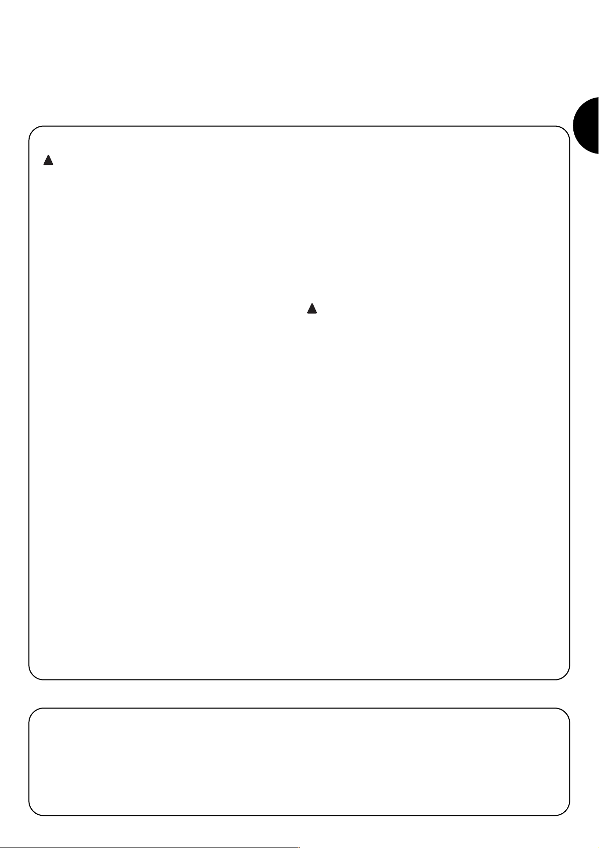
4.1) Standard installation layout (see fig. 3)
Fig. 3 illustrates the complete installation of a Soon gearmotor. The drawing shows the various components and cables required for connection, all assembled and positioned according to a standard layout.
Key to mechanical components in Fig. 3:
1 - Soon gearmotor
2 - Photocell
3 - Key-operated selector switch
4 - Post for photocell
5 - Flashing light
6 - Transmitter
7 - Main edge
Key to electric cables in Fig. 3:
A - Electric power line
B - Flashing light with aerial
C - Photocells
D - Key-operated selector switch
E - Main edge
1
3.3) Check product application limits (see fig. 2)
Check the application limits of the Soon model and relative accessories to be installed, assessing suitability of the characteristics to
meet the requirements of the environment and the limitations specified below.
• Ensure that the size of the sectional door is less than 20 m
2
.
• Ensure that the section door drive shaft is compatible with the
Soon outlet shaft, using the keys provided in the pack.
• Ensure that the wall fixing brackets are sufficiently long.
3.2) Check suitability of environment
• Check that the selected site of installation is compatible with the
overall dimensions of the Soon model (Fig. 2).
• Check that there are no obstacles along the trajectory of the sec-
tion door, which could obstruct total opening and closing movements.
• Check that the selected site of installation enables easy and safe
execution of manual manoeuvres
• Check that each device to be fixed is positioned on a solid surface
protected from the risk of accidental impact.
2
Page 5

5
GB
4.2) Install the mechanical components
After completing the preliminary installation tasks (such as digging
the routes for the electric cables or laying external ducting; possible
embedding of pipelines and other preparation work), assembly and
installation procedures can be started.
complete with all mechanical and electrical components of the Soon
gearmotor. Proceed in the order specified below.
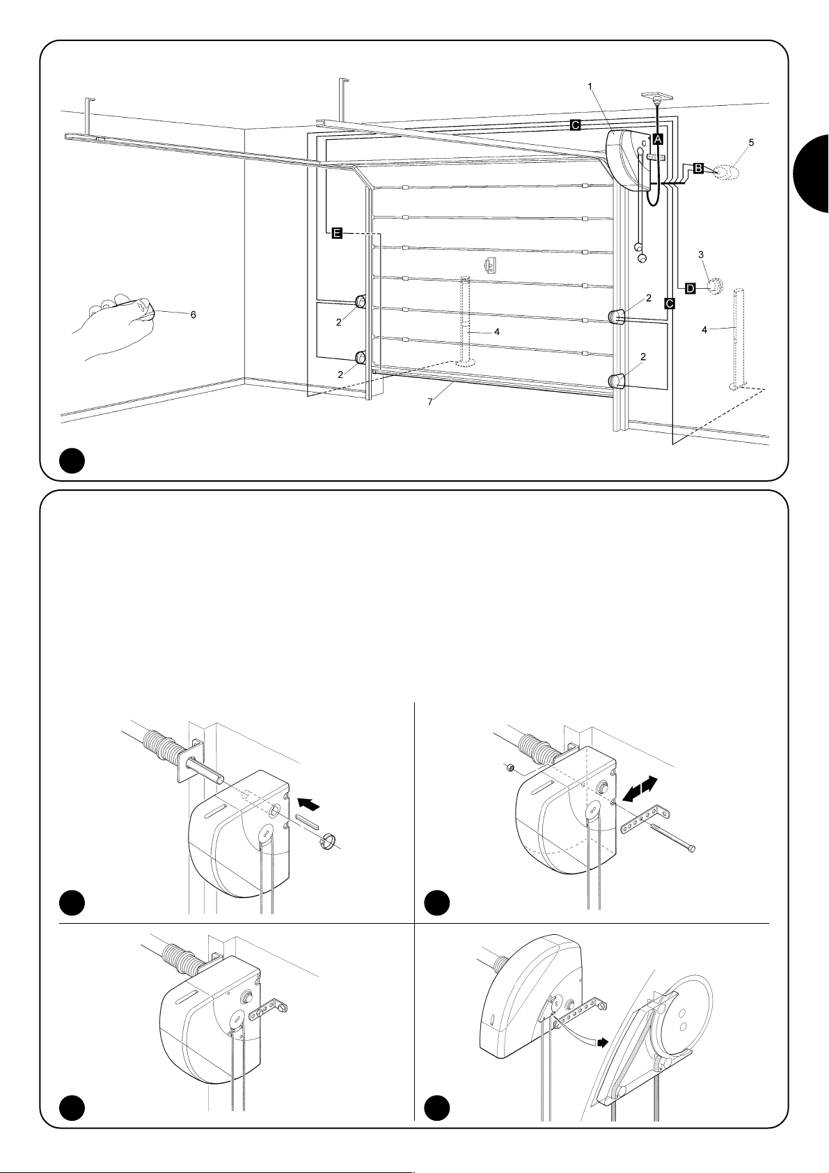
Mounting the Soon gearmotor (see Fig. 4)
1. (Fig. 4-a) Insert the Soon outlet shaft in the sectional door drive
shaft, coupling them using the keys provided in the pack.
Perform this operation with the door CLOSED.
2. (Fig. 4-b) Secure the bracket to the Soon gearmotor by means
of the screw, nut and washer supplied.
3. (Fig. 4-c) Fix the bracket to the wall by means of a plug (not supplied) suited to the wall material.
4. (Fig. 4-d) The Soon gearmotor can be installed horizontally using
the special gear (supplied) which should be fixed by means of
the three screws (supplied) in the position shown in the figure,
taking care to position the release mechanism cable outlets correctly.
4a 4b
4c 4d
3
Page 6
6
4.3) Laying electric cables (see fig. 3 and table 1)
On completion of installation of all mechanical components, pro-ceed with laying all electric cables required, with reference to Fig. 3 showing the typical location of these cables, and Table 1 which analyses the technical characteristics in detail.
The cables used for connecting the various devices must be suitable for the type of installation to be obtained: in
the case of installation in a covered environment or indoors, use cable type H03VV-F.
ELECTRIC CABLE SPECIFICATIONS
(The letters associated with the cables as indicated also in Fig. 3)
!
Note: (*) if the power cable is longer than 30 m, a cable with a larger section is required, (e.g. 3 x 2,5 mm2) and safety earthing is neces-
sary in the vicinity of the automation.
Connection Cable type Max. admissible length
A: Electric power line n° 1 cable (3 x 1.5 mm2) 30 m (*)
B: Flashing light n° 1 cable (2 x 1 mm2) 20 m
C: Aerial n° 1 shielded cable (type RG58) 20 m (recommended: less than5 m)
D: Photocell n° 1 cable (2 x 0.5 mm2) 30 m
E: Key-operated selector switch n° 1 cable (4 x 0.5 mm2) 50 m
F: Mobile edge connection n° 1 cable (2 x 0.5 mm2) 20 m
Table 1: cable list
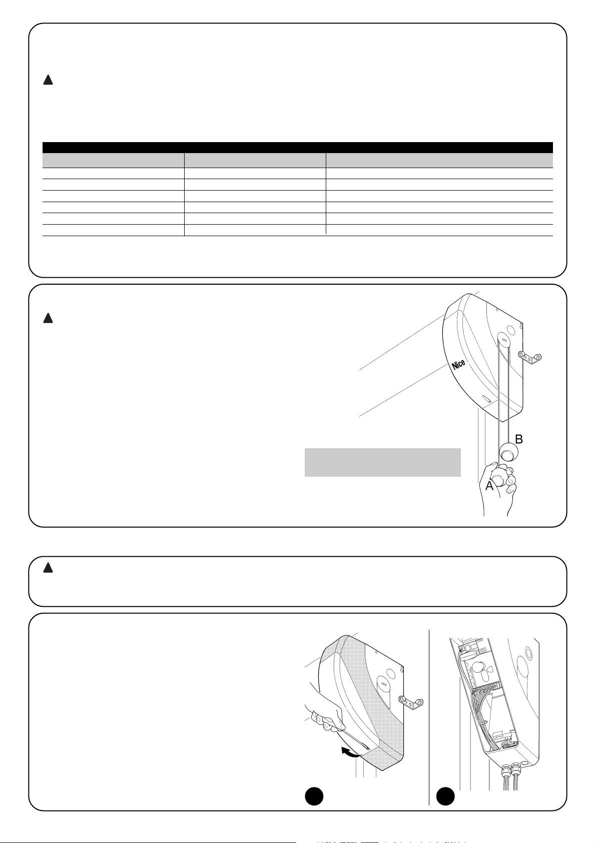
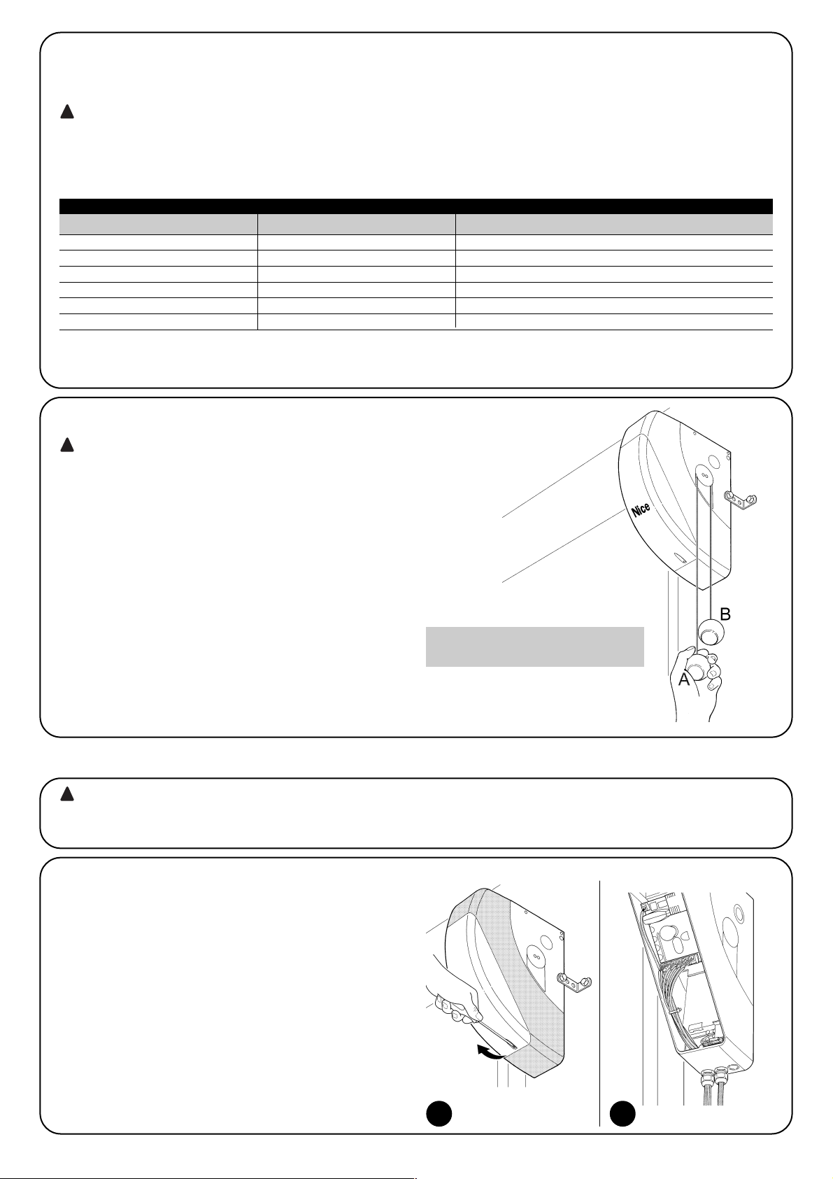
4.4) Manual lock and release procedure
Refer to this procedure when the text of the manual
requires “locking” or “release” of the SOON mechanism.
Note:
The release or locking manoeuvres of the mechanism must be performed exclusively with the gearmotor completely stationary.
• The manual operation must be per-formed in the event of a power
failure, system faults or when expressly requested in the manual.
• Manual release enables free travel of the sectional door.
!
To release - pull ball A
To lock - pull ball B
To ensure the Safety of the installer and avoid damage to automation components, before making electrical connections or connecting the radio receiver, ensure that the control unit is DISCONNECTED from the mains and any buffer
batteries
!
5) Make electrical connections
5.1) Connect all devices
All electrical connections must be made with the system disconnected from the power supply
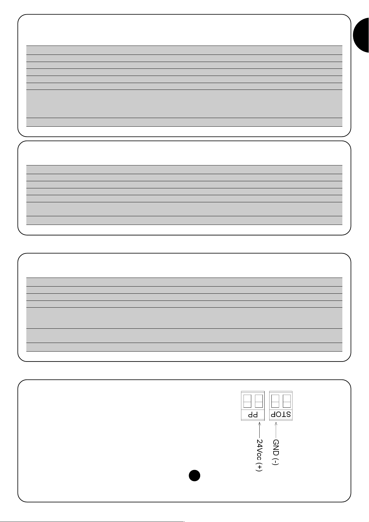
1. To remove the protection cover and access the SOON elec-tron-
ic control unit, remove the screw and pull the cover up-wards to
remove (Fig. 5).
2. Loosen the free cable clamp and route the cables through for
connection to the control unit terminals Leave a cable length of
20÷30 cm longer than necessary. See table 1 for the cable types
and Fig. 6 for connections.
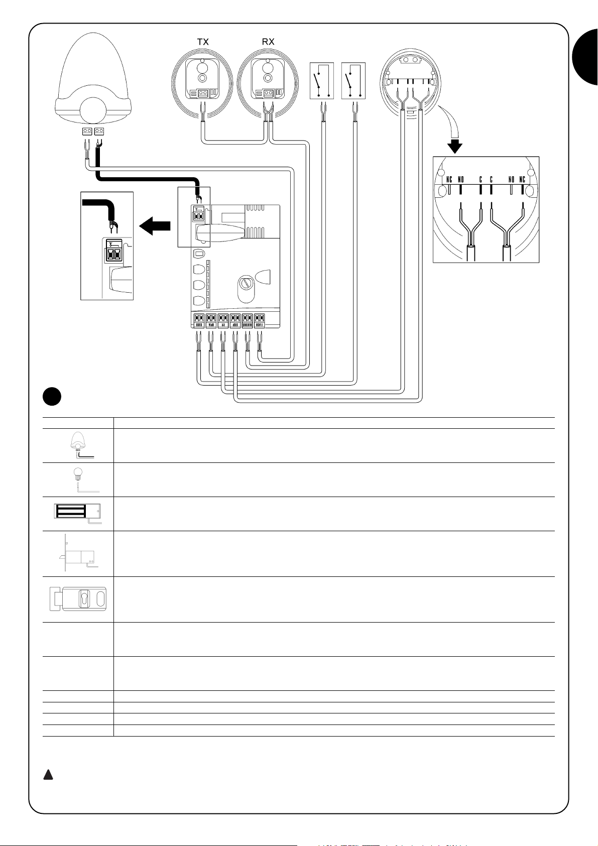
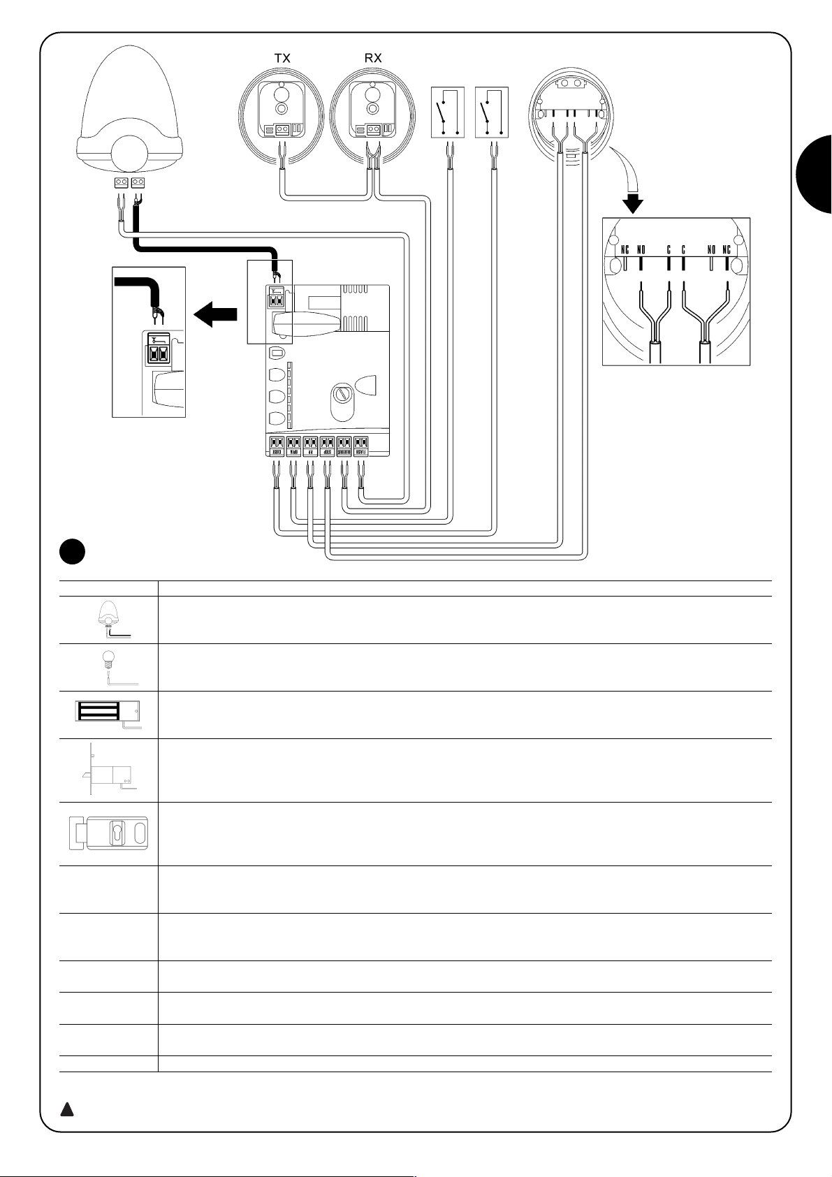
3. Make cable connections as shown in the diagram of Fig. 7. To
facilitate work, the terminals are removable
4. On completion of connections secure the cables by pressing
down the cable clamp. The excess aerial cable should be secured to the other cables with a clip.
65
Page 7
7
GB
7
FLASH this output is programmable (see SECTION 2 of the manual) to connect one of the following devices:
Flashing light If programmed as “flashing light” the “FLASH” output can be con-nected to a NICE “LUCY B” flashing
light with a 12V 21W car type lamp.
During the manoeuvre the light flashes at an interval 0.5s on and 0.5s off
“Door open indicator” output If programmed as “door open indicator” the “FLASH” output can be connected to a
24V max 5W indicator light for the door open signal.
It can also be programmed for other functions; see SECTION 2 of the manual.
Suction cup* If programmed as “suction cup” the “FLASH” output can be connected to a 24V max 10W suction cup
(versions with electromagnet only, without electronic devices). When the door is closed, the suction cup is activated to
lock the door in place. During the opening and closing manoeuvre it is deac-tivated.
Electric block* If programmed as “electric block” the “FLASH” output can be con-nected to a max. 24V electric lock
with latch (versions with electromagnet only, without electronic devices).
During the opening manoeuvre, the electric lock is activated and remains active to free the door and perform the
manoeuvre. In the closing manoeuvre ensure that the electric block re-engages mechanically.
Electric lock* If programmed as “electric lock” the “FLASH” output can be con-nected to a 24V max 10W electric lock
with latch (versions with electromagnet only, without electronic devices).
During the opening manoeuvre, the electric lock is activated for a brief interval to free the door and perform the
manoeuvre. In the closing manoeuvre ensure that the electric lock re-engages mechanically.
BLUEBUS This terminal enables the connection of compatible devices; all are connected in parallel with just two wires conveying
the electric power and communication signals. More information on BlueBUS is available in paragraph “5.2 - Connect
the BlueBUS devices”.
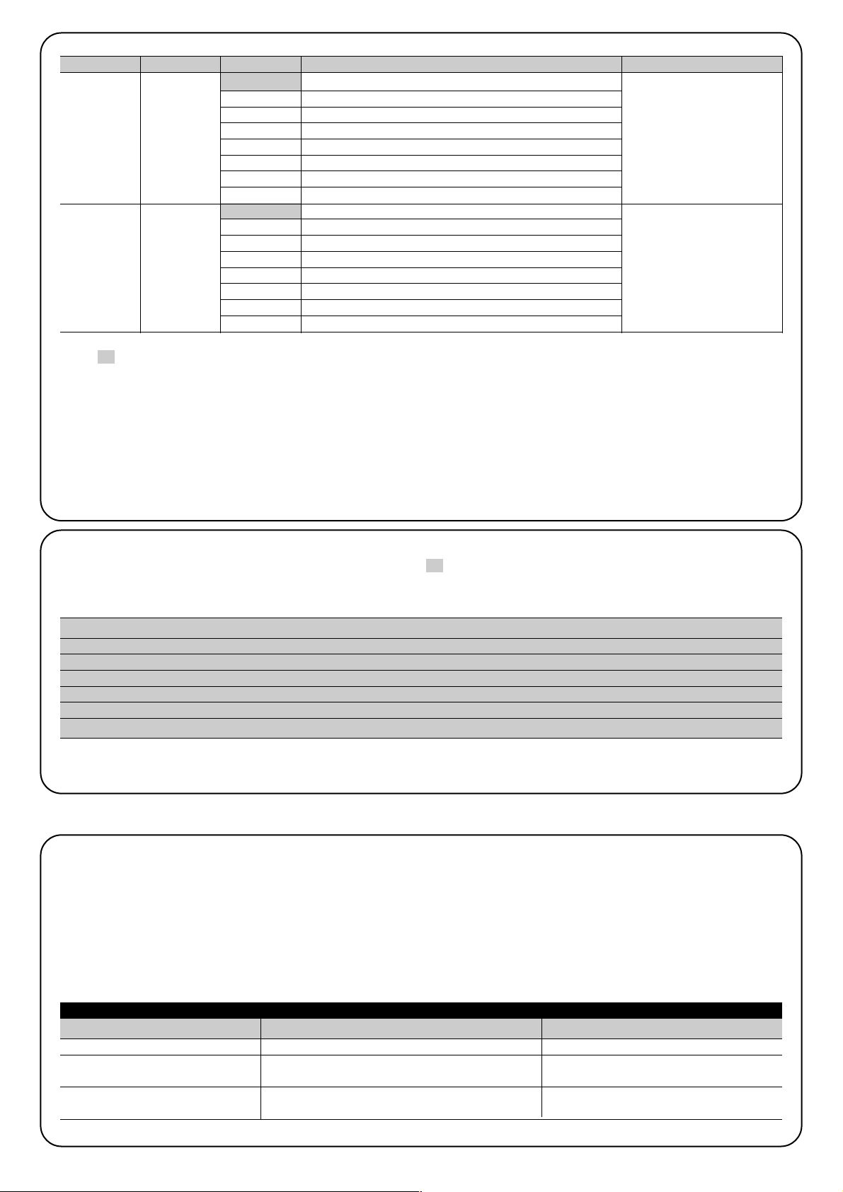
STOP Input for devices that block or shut down the manoeuvre in pro-gress; by setting the input accordingly, it is possible to connect
Normally Closed type contacts, Normally Open contacts, constant resistance or optical devices. More information on STOP is
available in paragraph “5.3 - Connect devices to the STOP input”.
SS Input for devices that control movement in Step-Step mode, ena-bling the connection of Normally Open contacts.
OPEN Input for devices that control opening movement only, enabling the connection of Normally Open contacts.
CLOSE Input for devices that control closing movement only, enabling the connection of Normally Open contacts.
AERIAL input for connection of the aerial for the radio receiver (the aerial is incorporated on LUCY B)
* Only devices containing exclusively the electromagnet can be connected.
Never use devices other than those specified
!
Page 8

8
5.2) Connect bluebus devices
BlueBUS is a technology that enables the connection of compatible
devices with just two wires conveying the electric power and communication signals. All devices are connected in parallel on the same
2 BlueBUS wires, without the need to observe polarity; each devices
is recognised individually as it is assigned with an exclusive address
during installation. BlueBUS can be used, for example, to connect
the following: photocells, safety devices, control pushbuttons, indicator lamps, etc. The SOON control unit recognises each one of the
devices connected by means of a specific self-learning phase and is
able to detect all possible faults in maximum safety and with the
utmost precision. For this reason each time a device is connected to
or removed from BlueBUS the self-learning phase must be repeated, as described in paragraph “7.1 - Memorising devices”.
5.2.2) Photosensor ft210b
Photosensor FT210B combines in a single device a force limitation
system (type C to the standard EN12453) and a presence detector
that detects obstacles on the optic axis between the transmitter TX
and receiver RX (type D to standard EN12453). On photosensor
FT210B the signals of the sensitive edge status are sent via the photocell beam, integrating the 2 systems in a single device. The transmitting section on the mobile leaf is battery-powered, thus eliminating unsightly connection system; special circuits reduce battery consumption to guarantee a lifetime of up to 15 years (see details of the
estimated lifetime in the product instructions).
A single FT210B device combined with a sensitive edge (e.g. TCB65)
enables the safety level of the “main edge” as required by the standard
EN12453 for any “type of use” and “type of activation”. Photosensor
FT210B combined with “resistive” sensitive edges (8,2Kohm), is safe
with single faults (class 3 to standard EN 954-1). It is equipped with a
special anti-collision circuit to prevent interference with other detectors, even not synchronised, and enables the addition of other photocells; for example in the case of transit of heavy vehicles where a second photocell is normally positioned at 1 m from the ground.
For further information on connection methods and address assignment, see the instruction manual for FT210B.
5.3) Connect devices to stop input
STOP is the input that causes immediate shutdown of the movement followed by a brief inversion of the manoeuvre This input can
be connected to devices with an output for NO normally open contact, NC normally closed contact, constant resistance 8,2KΩ or optical devices, such as sensitive edges.
As in the case of BlueBUS, the control unit recognises the type of
device connected to the STOP input during the self-learning phase
(see paragraph “7.1 - Memorising devices”); after which a STOP
command is activated whenever a variation with respect to the
learned status is detected.
When set accordingly, more than one device can be connected to
the STOP input, also different from one another:
• Several NO devices can be connected in parallel with no limit to
number.
5.2.1) Photocells
The “BlueBUS” system enables, by means of address assignment
using the specific jumpers, recognition of the photocells by the control unit and assignment of the correct detection function. The address assignment procedure is performed both on the TX and RX
(setting the jumpers in the same way) and ensuring that there are no
other pairs of photocells with the same address.
On an automation for sectional doors with a SOON gearmotor, photocells can be installed as shown in Fig. 8. After installation the selflearning phase must be repeated on the control unit, as described in
paragraph “7.1 - Memorising devices”.
8
PHOTO
Photocell h = 50
With activation on closing
PHOTO II
Photocell h = 100
With activation on closing
PHOTO 1
Photocell h = 50
With activation on closing and opening
PHOTO 1 II
Photocell h = 100
With activation on closing and opening
PHOTO 2
Photocell
With activation on opening
PHOTO 2 II
Photocell
With activation on opening
PHOTO 3
CONFIGURATION NOT ADMITTED
Table 2: photocell addresses
Photocell Jumpers Photocell Jumpers
Page 9

9
GB
5.4) Connect electrical power supply
For electrical power supply of SOON, simply insert the plug in a mains socket. If necessary, use a commercially available adapter if the SOON
plug does not correspond to the mains socket available.
• Several NC devices can be connected in parallel with no limit to
number.
• Two devices with constant resistance 8,2KΩ can be connected in
parallel; if there are more than 2 devices then all must be connected in cascade, with a single terminating resistance of 8,2KΩ.
• NO and NC combinations are possible by placing the 2 contacts
in parallel, taking care to place a 8,2KΩ resistance in parallel to the
NC contact (thus enabling the combination of 3 devices: NO, NC
and 8,2KΩ).
If the STOP input is used to connect devices with safety functions, only devices with the constant resistance
8,2KΩ output or OPTO SENSOR optical devices guarantee
safety class 3 against faults, according to standard EN
954-1.
For connection of an OPTO SENSOR type optical device, make connections as shown in Fig. 9:
!
9
The following operations will be performed on live electrical circuits and therefore manoeuvres may be hazardous!
Therefore take great care and never perform operations alone.
On completion of component installation and electrical connections, a number of simple checks must be made to ensure correct operation
of the system operation, before proceeding. Perform the following operations as specified and cross off the points as conformity of results is
verified.
!
6) Initial system start-up - checks
7) Memorising devices and positions
6.1) Operating test
As soon as SOON is powered up, proceed as follows:
K Check that the BlueBUS led flashes regularly at the frequency of
one flash per second.
K If photocells are present, ensure that the relative leds are also
flashing (both on TX and RX); the type of flash is not significant,
as this depends on other factors.
K Check that the device connected to the FLASH output is off.
K Check that the courtesy light is off.
If none of these conditions occur, disconnect the power supply immediately and check the electrical connections thoroughly.
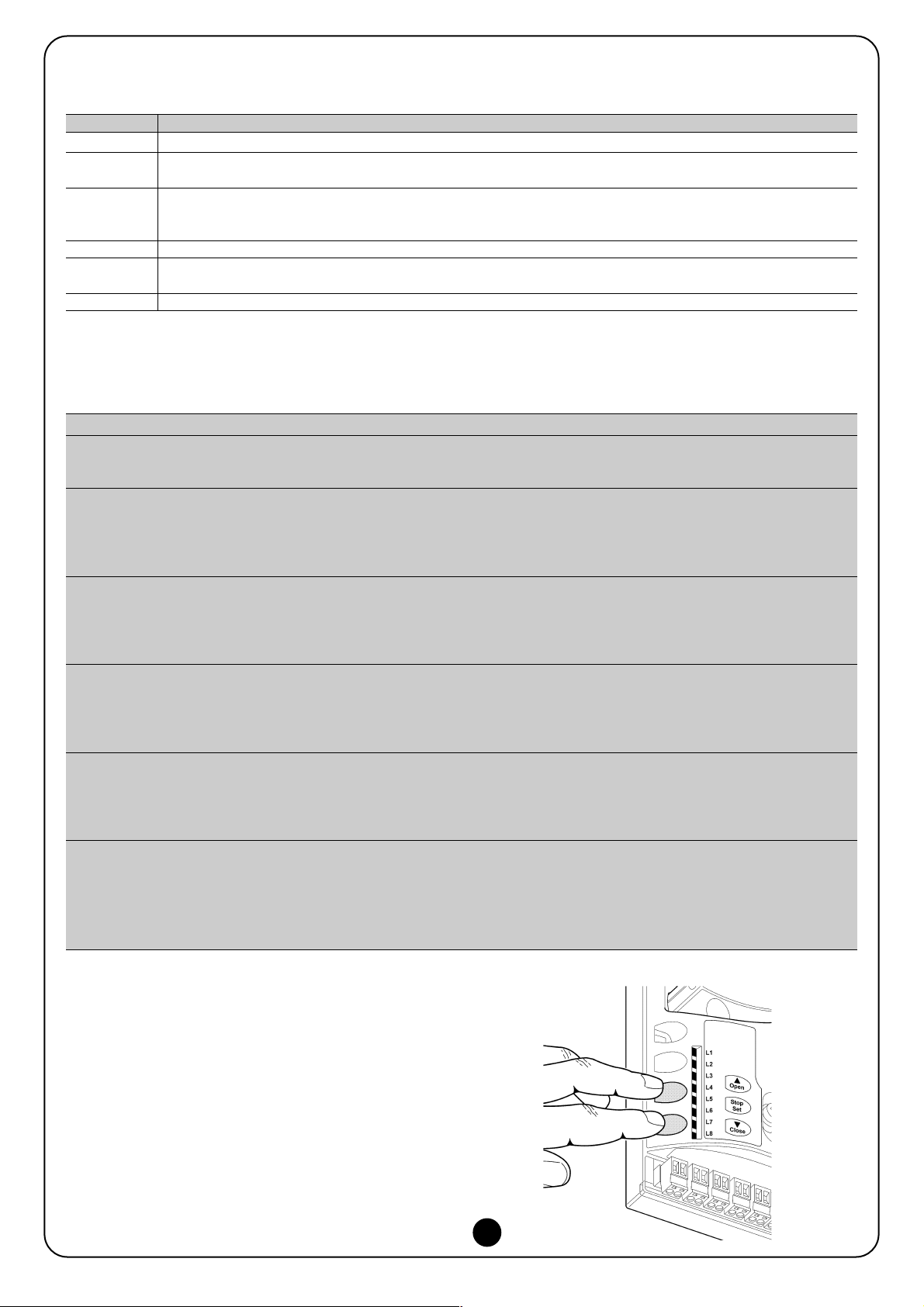
7.1) Memorising devices
After connecting to the power supply, the control unit must recognise the devices connected to the inputs BlueBUS and STOP Before this phase, leds L1 and L2 flash to indicate that the device selflearning process must be performed.
The device self-learning phase must be performed
even if no device is connected
1. Press and hold keys [▲] and [Set]
2. Release the keys when leds L1 and L2 start to flash quickly (after
around 3s)
3. Wait a few seconds for the control unit to finish device self-learn-
ing.
At the end of the self-learning process, the STOP led must remain lit,
while leds L1 and L2 turn off (where relevant leds L3 and L4 start
flashing).
The phase of self-learning the devices connected can be repeated
at any time also after installation, such as in the case that a device is
added.
!
10
Page 10
10
7.2) Memorising positions
After self-learning the devices, the control unit must recognise the door opening and closing positions. Up to 6 positions can be programmed
as follows:
Position Meaning
A1 Maximum required opening position. When the door reaches this position it stops.
RA1 Slowdown start position during opening manoeuvre. When the door reaches this position the motor decelerates to the
minimum speed.
RINT Intermediate slowdown position in closing manoeuvre. When this point is programmed, the door starts to decelerate at
approx. 50 cm beforehand, to pass the position RINT to minimum speed. On passing the RINT position the motor
returns to the set speed.
AP Partial opening position. This is the position at which the door stops after receiving a partial opening command.
RA0 Slowdown start position during closing manoeuvre. When the door reaches this position the motor decelerates to the
minimum speed.
A0 Maximum closing position. When the door reaches this position it stops.
When the positions have not been acquired, leds L3 and L4 flash.
The position memorisation procedure is described below: Positions A1 and A0 must be programmed, while the other positions can be
skipped. In the latter case, they are calculated automatically by the control unit.
1. Press [Set] + [▼] for 3 seconds to enter in position memorisation mode.
Led 1 flashes: Position A1 programming
2 Use keys [▲] or [▼] to move the door to the maximum opening position.
3. Press [Set] for 2 seconds to confirm position A1. Led L1 remains lit.
Led 2 flashes: Position RA1 programming
4. If the opening slowdown position programming is not required, press the key [Set] twice quickly to skip to the next programming;
led L2 remains off. Otherwise proceed with the sequence.
5. Use keys [▲] or [▼] to move the door to the opening deceleration position.
6. Press [Set] for 2 seconds to confirm position RA1. Led L2 remains lit.
Led L4 flashes: Position RINT programming
7. If the intermediate slowdown position programming is not required, press the key [Set] twice quickly to skip to the next
programming; led L4 remains off. Otherwise proceed with the sequence.
8. Use keys [▲] or [▼] to move the door to the intermediate deceleration position.
9. Press [Set] for 2 seconds to confirm position RINT. Led L4 remains lit
Led L5 flashes: Position RAP programming
10. If the partial opening position programming is not required, press the key [Set] twice quickly to skip to the next programming; led
L5 remains off. Otherwise proceed with the sequence
11. Use keys [▲] or [▼] to move the door to the partial opening position.
12. Press [Set] for 2 seconds to confirm position RAP. Led L5 remains lit
Led L7 flashes: Position RA0 programming
13. If the closing slowdown position programming is not required, press the key [Set] twice quickly to skip to the next programming;
led L7 remains off. Otherwise proceed with the sequence
14. Use keys [▲] or [▼] to move the door to the closing deceleration position.
15. Press [Set] for 2 seconds to confirm position RA0. Led L7 remains lit.
Led L8 flashes: Position A0 programming
16. Use keys [▲] or [▼] to move the door to the maximum closing position.
17. Press [Set] for 2 seconds to confirm position A0. Led L8 remains lit.
18. On release of [Set] all leds turn off.
19. Give an open command by pressing [Open] to execute a complete opening manoeuvre.
20. Give a close command by pressing [Close] to execute a complete closing manoeuvre.
During these manoeuvres, the control unit memorises the force
required for the opening and closing movements
It is important that these preliminary manoeuvres are not
interrupted for example by a STOP command.
The position learning phase can be repeated at any time also after
installation, by simply repeating the procedure from point 1. However, if only one position needs to be modified, repeat the se-quence
from point 1 and skip programming of the positions not involved by
pressing the key [Set] twice quickly for each position to skip.
11
Page 11
11
GB
8) Perform final testing of system
8.1) Final testing
Each component of the automation, such as the sensitive
edges, photocells, emergency stop, etc., requires a specific testing phase; for these devices the specific procedures in the respective instruction manuals must be performed. To test SOON proceed as follows:
1. Ensure that all specifications in chapter 1 “WARNINGS” have
been observed.
2. Release the door from the motor by pulling the release cord
down. Check that the door can be moved manually in opening
and closing with a maximum force of 225N.
3. Lock the door to the motor by pulling the locking cord down.
4. Using the selector or radio transmitter, perform door opening
and closing tests and ensure that the movement corresponds to
specifications.
5. Test several times to assess smooth operation of the door and
check for any defects in assembly or adjustment and any possible points of friction.
6. Check operation of all system safety devices one at a time (photocells, sensitive edges, etc.) In particular, each time a device is
activated the “BlueBUS” led on the control unit must flash rapidly twice to confirm acknowledgement of the event.
7. To check the photocells, and in particular to ensure there is no
interference with other devices, pass a cylinder with diameter of
5cm and length 30cm on the optical axis, first close to the TX,
then close to the RX and lastly at the centre between the two
and ensure that in all cases the device engages, changing from
the active status to alarm status and vice versa, and that the
envisaged action is generated on the control unit, for example: in
the closing manoeuvre it inverts movement.
8. If hazardous situations generated by the moving door are protected by means of impact force limitation, measure the force as
specified in the standard EN 12445. If speed and motor force
controls are used as auxiliary functions with the system for
reduction of impact force, test and identify the setting that
obtains the best results.
8.2) Commissioning
Commissioning can only be performed after positive
results of all test phases on Soon and the other devices
present. Partial or “makeshift” commissioning is strictly
prohibited.
1 The prepared automation technical documentation should be
conserved for at least ten years and must contain at least the following: overall drawing of the automation, electrical wiring diagram, risk assessment and relative solutions adopted, manufacturer's declaration of conformity for all devices used (in the case
of Soon, use the EC declaration of conformity en-closed); copy
of the operation instruction manual and mainte-nance schedule
for the automation.
2. Affix a dataplate on the door, specifying at least the following
data: type of automation, name and address of manufacturer
(responsible for commissioning), serial number, year of construction and CE mark
3. Permanently affix a label or plate in the vicinity of the door, indicating the operations for door release and manual manoeuvres.
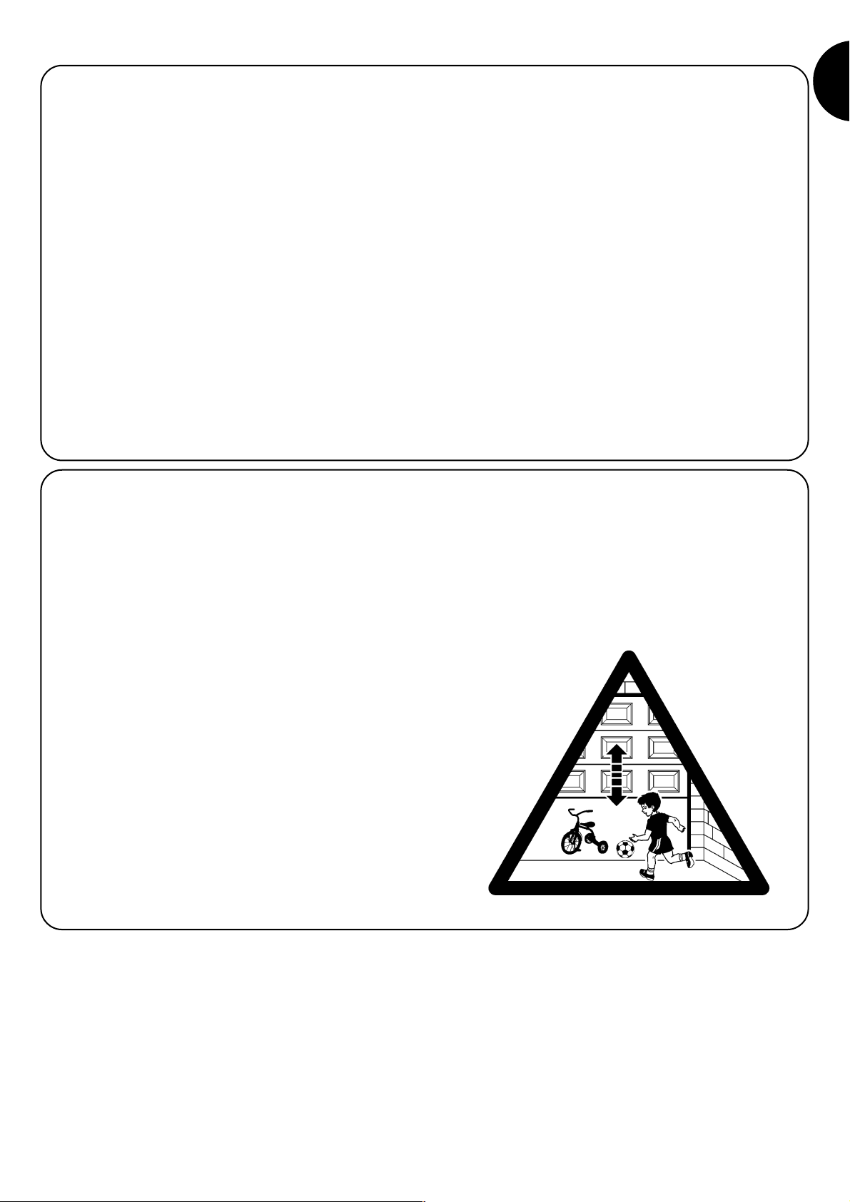
4. Permanently affix a label or plate on the door, bearing this image
(min. height 60 mm).
5. Prepare and provide the owner with the declaration of conformity of the automation.
6. Prepare and provide the owner with a the manual “Automation
operation instructions and warnings”.
7. Prepare and provide the owner with the automation maintenance schedule (containing all prescriptions for maintenance of individual devices).
8. Before commissioning the automation, ensure that the owner is
adequately informed in writing (such as in the automation
instruction and warning manual) of all associated risks and
hazards.
Page 12
12
SECTION 2 describes how to personalise operation of the automation, by means of settings and options to be memorised in the control unit.
The final section is dedicated to troubleshooting, maintenance and disposal of the product.
9) Instructions for personalised automation operation
The SOON control unit is equipped with a number of programmable
functions; function settings are entered by means of the 3 keys on
the control unit: [▲] [Set] [▼] and are displayed by means of 8
leds: L1….L8.
The programmable functions available on SOON are divided into 2
levels:
Level 1: functions settable in ON-OFF mode (enabled or disabled);
in this case each led L1….L8 indicates a function, if lit the function
is enabled, if off the function is disabled; see Table 3.
Level 2: parameters settable on a scale of values (from 1 to 8); in
this case each led L1….L8 indicates a set value from the possible
8; see Table 4.
10) Settings
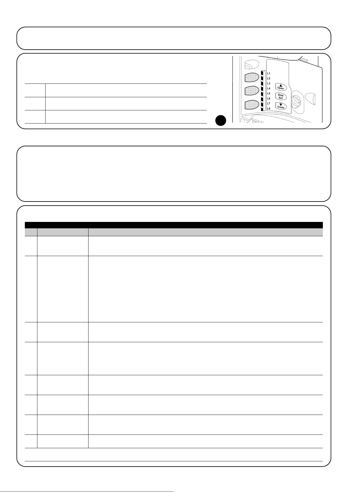
The “OPEN” key enables the user to open the door or scroll up through
the programming steps
The “STOP” key enables the user to stop the manoeuvre, or when pressed
for 5 seconds enables access to programming mode.
The “CLOSE” key enables the user to close the door or scroll down
through the programming steps
9.1) Programming keys
The SOON control unit is fitted with 3 keys which can be used both for the control of
the unit during testing and the programming pro-cedure:
12
OPEN
▲
STOP
SET
CLOSE
▼
Led Function Description
L1 Automatic closure This function enables automatic closure of the gate after a set pause time; by default the Pause Time is set
at 30 seconds, but can be modified to 10, 20, 40, 60, 80, 120, 160 or 200 seconds.
If the function is disabled, operation is “semiautomatic”.
L2 Close After Photo This function enables the system to keep the door open only for the time required for transit, in fact activation of
"Photo" always causes automatic closure with a pause time of 5s (regardless of the set value)
The behaviour changes according to whether the function "Automatic closure" is enabled or disabled.
With "Automatic closure" disabled: the door always reaches the totally open position (even if Photo is
disengaged beforehand). On release of Photo, automatic closure is activated with a pause of 5s.
With "Automatic closure" enabled: the opening manoeuvre stops immediately after release of the
photocells and automatic closure is activated with a pause of 5s.
The function "Close After Photo" is always disabled in manoeuvres interrupted by means of a Stop
command. If the function "Close After Photo" is disabled, the pause time is as set; otherwise there is no
auto-matic closure if the function is disabled.
L3 Always Close The function “Always Close” is activated, causing closure, when an open door is detected on restoral of
power supply. For safety reasons, the manoeuvre is preceded by a 3-second pre-flashing interval.
If the function is disabled, the door remains stationary on restoral of power.
L4 Stand-By This function enables reduction of consumption to a minimum. If this function is enabled, 1 minute after
completion of the manoeuvre the control unit turns off the BlueBUS output (and therefore the devices) and
all leds, with the exception of the BlueBUS led, which flashes at a slower speed. When the control unit
receives a command it restores full operating conditions. If the function is disabled, no reduction in
consumption is enabled.
L5 Long inversion This function enables the selection of the type of inversion executed by the door after activation of a STOP
command or the force limiter device. If the function is disabled, inversion is short (approx. 15cm). If the
function is enabled, inversion continues through to the maximum opening or closing position.
L6 Preflashing The pre-flashing function is added to a pause of 3s between activation of the flashing light and the start of
the manoeuvre to warn of a hazardous situation. If preflashing is disabled, activation of the flashing light
coincides with the start of the manoeuvre.
L7 Sensitivity This function enables a significant increase in sensitivity of the motor for obstacle detection. If used in
support of detection of the impact force, the parameters “Speed” and “Motor force” must also be set in the
level 2 menu.
L8 Compensation This function enables recovery of the extension over time of the metal tops of the door and is subordinate
to the use of a 8,2KΩ resistive type senstivie edge or OSE optic sensor.
During normal operation of SOON, when no manoeuvre is in progress, leds L1….L8 are lit or off depending on the status of the associated
function, for example L1 is lit if the function “Automatic closure” is enabled.
Table 3: list of programmable functions: level 1
10.1) Level 1 functions
Page 13
13
GB
Pause Time
Funzione P.P.
Motor speed
FLASH
output.ì
Motor Force
on opening
Motor Force
on closing
L1
L2
L3
L4
L5
L6
L7
L8
L1
L2
L3
L4
L5
L6
L7
L8
L1
L2
L3
L4
L5
L6
L7
L8
L1
L2
L3
L4
L5
L6
L7
L8
L1
L2
L3
L4
L5
L6
L7
L8
L1
L2
L3
L4
L5
L6
L7
L8
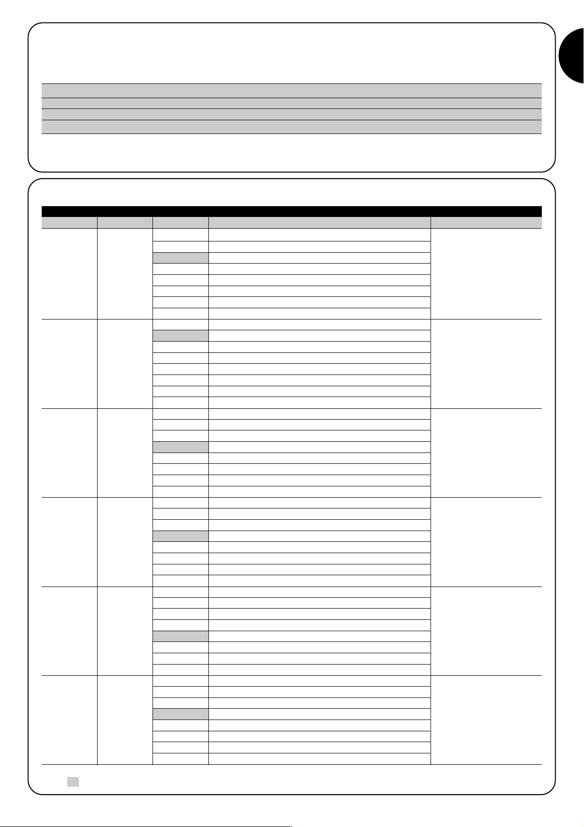
10 seconds
20 seconds
40 seconds
60 seconds
80 seconds
120 seconds
160 seconds
200 seconds
Open - stop - close - stop
Open - stop - close- open
Open - close - open - close
Apartment block
Apartment block 2 (more than 2” generates stop)
Step-step 2 (less than 2” generates partial open)
Hold-to-run
Opening in “semiautomatic”, closure in “hold-to-run””
Speed 1 (30% - slow)
Speed 2 (44%)
Speed 3 (58%)
Speed 4 (72%)
Speed 5 (86%)
Speed 6 (100% - fast)
Open V4, close V2
Open V6, close V4
Door Open Indicator
Active if door closed
Active if door open
Flashing light
Electric block
Electric lock
Suction cup
Maintenance indicator
Force 1 (low)
Force 2
Force 3
Force 4
Force 5
Force 6
Force 7
Force8 (high)
Force 1 (low)
Force 2
Force 3
Force 4
Force 5
Force 6
Force 7
Force8 (high)
10.3) Level 2 Functions (settable parameters)
Table 4: list of programmable functions: level 2
Input Led Parameter Led (level) Value Description
Sets the pause time, i.e. the
time before automatic
closure. Applied only when
auto-matic closure function
is enabled
Sets the sequence of
commands associated with
the SS input or the 1st
radio command.
Sets the motor speed
during normal travel.
Selects the device
connected to the FLASH
output.
Sets the system for
controlling motor force, to
adapt it to the weight of the
door during the opening
manoeuvre.
Sets the system for
controlling motor force, to
adapt it to the weight of the
door during the closing
manoeuvre.
Note: “ “ represents factory settings SEGUE
L1
L2
L3
L4
L5
L6
10.2) Level 1 programming
By default level 1 function are all set to OFF, but can be modified at any time as described below. Take care during modification procedures,
as there is a maximum time interval of 10 seconds between pressing one key and another; otherwise the system exits the procedure automatically memorising the changes made up to that time.
Wait 10s to exit the programming mode automatically after the maximum time interval.
Note: points 3 and 4 can be repeated during the same program-ming phase to set other functions to ON or OFF.
1. Press and hold [Set] for approx. 3s
2. Release [Set] when led L1 starts flashing.
3. Press keys [▲] or [▼] to move the flashing led to the led associated with the function to be modified
4. Press [Set] to change the status of the function (short flash = OFF; long flash = ON)
Page 14
14
SOON enables the user to be notified when a maintenance
check needs to be performed on the automation. The number of manoeuvres after which the signal can be enabled is
selectable from 8 levels, by means of the modifiable parameter “Maintenance notifica-tion” (see Table 4).
Adjustment level 1 is “automatic” and takes into account manoeuvre
stress, i.e. force and duration of the manoeuvre, while the other adjustments are set on the basis on the number of manoeuvres.
The maintenance requirement notification is via the flashing light or the
maintenance indicator, depending on the relative settings (see Table 4).
On the basis of the number of manoeuvres performed with respect to the
programmed limit, the Flash flashing light and maintenance indicator activate the signals as described in Table 5.
11) Maintenance notification
Maintenance
notification
Fault log list
L1
L2
L3
L4
L5
L6
L7
L8
L1
L2
L3
L4
L5
L6
L7
L8
Automatic (based on gravity of manoeuvre)
1.000
2.000
4.000
6.000
8.000
10.000
12.000
Result of 1stmanoeuvre (most recent)
Result of 2ndmanoeuvre
Result of 3rdmanoeuvre
Result of 4thmanoeuvre
Result of 5thmanoeuvre
Result of 6thmanoeuvre
Result of 7thmanoeuvre
Result of 8
th
manoeuvre
Input Led Parameter Led (level) Value Description
Controls the number of
manoeuvres after which the
automation maintenance
notification signal is sent
(see paragraph “13 Maintenance notification”).
Enables the user to check
the type of faults occurring
in the last 8 manoeuvres
(see paragraph “14 Fault
log list”).
Note: “ ” represents factory settings
All parameters can be adjusted as required without any contraindications, only the “Motor force on opening” and “Motor force in closing”
may require special attention:
• Use of high force values are not recommended to compensate for the fact that the leaf has anomalous points of friction; excessive force
may impair the safety system and damage the leaf.
• If the “Motor force control” is used in support of the system for impact force reduction, after each adjustment the force measure-ment pro-
cedure must be performed, as envisaged by standard EN 12445.
• Wear and atmospheric conditions influence movement of the gate; and force settings should be checked periodically.
L7
L8
10.4) Level 2 programming
By default the settable parameters are set as shown in Table 4 with: “ ” but can be modified at any time as described below. Take care
during modification procedures, as there is a maximum time interval of 10 seconds between pressing one key and another; otherwise the
system exits the procedure automatically memorising the changes made up to that time.
Wait 10s to exit the programming mode automatically after the maximum time interval.
Note: points 3 to 7 can be repeated during the same programming phase to modify other parameters.
1. Press and hold [Set] for approx. 3s
2. Release [Set] when led L1 starts flashing.
3. Press keys [▲] or [▼] to move the flashing led to the “in-put led” associated with the parameter to be modified
4. Press and hold [Set] during steps 5 and 6
5. Wait approx. 3s after which the led associated with the current level of the parameter to be modified will light up.
6. Press keys [▲] or [▼] to move the led associated with the parameter value
7. Release [Set]
Number of manoeuvres Signal on Flash Signal on maintenance indicator
Less than 80% of the limit Normal (0.5s on, 0.5s off) On for 2s at the start of opening
Between 81 and 100% of the limit At the start of the manoeuvre, remains lit for 2s then Flashes throughout manoeuvre
proceeds normally
Over 100% of the limit At the start of the manoeuvre, remains lit for 2s then Flashes continuously.
proceeds normally
Table 5: maintenance notification signal with Flash and maintenance indicator
Page 15
15
GB
11.1) Check of number of manoeuvres performed
The function “Maintenance notification” enables the user to check the number of manoeuvres performed as a percentage of the set limit.
To check, proceed as follows:
1. Press and hold [Set] for approx. 3s
2. Release [Set] when led L1 starts flashing.
3. Press keys [▲] or [▼] to move the flashing led to L7, i.e. the “input led” associated with the parameter to be “Maintenance notification”
4. Press and hold [Set] during steps 5, 6 and 7
5. Wait approx. 3s after which the led associated with the current level of the parameter “Maintenance notification” will light up.
6. Briefly press keys [▲] and [▼].
7. The led corresponding to the selected level flashes a few times. The number of flashes indicates the percentage of manoeuvres
performed (in multiples of 10%) with respect to the set limit. For example: when the maintenance notification is set on L7 i.e. 10000, 10%
corresponds to 1000 manoeuvres; if the indicator led flashes 4 times, this means that 40% of the maximum number of manoeuvres
has been reached (i.e. between 4000 and 4999 manoeuvres). If 10% has not yet been reached, the led does not flash at all.
8. Release [Set]
SOON enables the display of any faults that have occurred in the last 8 manoeuvres, for example interruption of a manoeuvre due to activation of a photocell or sensitive edge. To check the list of faults, proceed as follows:
1. Press and hold [Set] for approx. 3s
2. Release [Set] when led L1 starts flashing.
3. Press keys [▲] or [▼] to move the flashing led to L8, i.e. the “input led” associated with the parameter “Fault log”
4. Press and hold [Set] during steps 5 and 6
5. Wait approx. 3s after which the leds corresponding to the manoeuvres subject to faults will light up. Led L1 indicates the result of
the most recent manoeuvre, while led L8 indicates the result of the eighth manoeuvre. If the led is lit this means that faults have
occurred during the manoeuvre; if off this means that the manoeuvre was completed without faults.
6. Press the keys [▲] and [▼] to select the required manoeuvre: The corresponding led emits a number of flashes equal to those
normally emitted by the flashing light after a fault.
7. Release [Set]
11.2) Manoeuvre counter reset
After performing system maintenance the manoeuvre counter must be reset. Proceed as described in table:
1. Press and hold [Set] for approx. 3s
2. Release [Set] when led L1 starts flashing.
3. Press keys [▲] or [▼] to move the flashing led to L7, i.e. the “input led” associated with the parameter “Maintenance notification”
4. Press and hold [Set] during steps 5 and 6
5. Wait approx. 3s after which the led associated with the current level of the parameter “Maintenance notification” will light up.
6. Press and hold keys [▲] and [▼] for at least 5 seconds, then release. The led corresponding to the selected level shows a series of
quick flashes to indicate that the manoeuvre counter has been reset.
7. Release [Set]
If external devices need to be powered, such as a proximity reader
for transponder badges or the lighting of a key-operated selector
switch, power can be supplied as shown in figure 12. The supply
voltage is 24Vcc -30% ÷ +50% with maximum available current of
100mA.
13) Connecting other devices
12) Fault log list
12
Page 16

16
14) Further details: special functions
14.1) “Always open” function
The “always open” function is a feature of the control unit that enables continuous activation of an opening manoeuvre when the “Step-bystep” command lasts more than 2 seconds; this can be useful for example to connect the SS terminal with the contact of a programme clock
to keep the gate open during a specific time band. This feature is valid regardless of the setting of the input SS with exception of the setting
as “Apartment block 2”, see parameter “Function SS” in Table 4.
15) Automation operation by means of transmitter and “SM” radio receiver
The Control unit is fitted with a connector specially for the installation
of a radio receiver with “SM” type connection (Fig. 13), to control the
automation using a radio transmitter (receiver and transmitter are
optional accessories). The four Outputs of the Receiver enable delivery of the following commands to the control unit:
If the aerial incorporated in LUCYB or other type of external aerial is
not used, screw the rigid cable supplied with the receiver onto the
aerial terminal (Fig. 14).
14.2) “Move anyway” function
In the event that a safety device malfunctions or is out of service, the gate may still be moved in “hold-to-run” mode. For details, refer to the
paragraph “Control with safety devices out of service” in the enclosure “Instructions and warnings for the SOON gearmotor user”.
Output N°1 “SS” command (Step-Step)
Output N°2 “Partial open” command
Output N°3 “Open” command
Output N°4 “Close” command
Table 6: commands with receiver SMXI, SMXIS
16) Automatic fault finding and diagnostics
During normal operation, the control unit constantly monitors the automation processes and is designed to indicate any faults that arise, by
means of a pre-set sequence of flashes emitted by the flashing light, courtesy light and the “BlueBUS Led” (the diagnostics flashes always
refer to the last action performed by Soon) For an explanation of the number of flashes and associated cause, refer to the table below:
Table 7: diagnostics flash signals
13 14
n° flash Cause
1 BlueBUS synchronisation error
2 Activation of Photocell or Phototest error
3 Gearmotor force insufficient or obstacle detected during travel
4 Stop device activation
5 Memory parameter error
6 Internal manoeuvre limiter activation
7 Power failure on motor circuits
8 Overcurrent on motor circuits
Page 17
17
GB
17) What to do if… (Troubleshooting guide)
This is a small guide to solving the most common problems that may
arise during installation and programming of the automation.
•
…no manoeuvre is activated and the “BlueBUS” led does
not flash
- Ensure that Soon is powered from a 230V mains.
Ensure that fuses F1 and F2 (Fig. 15) are not blown; in this case,
identify the cause of the fault and then replace with versions of the
same current value and specifications.
•
…no manoeuvre is activated and the flashing light is off
- Check that the command is effectively received. If the command is
delivered to the input SS the relative “SS” led must light up; otherwise if the radio transmitter is used, the “BlueBUS” led flashes
quickly twice.
• …
the manoeuvre does not start and the courtesy light
flashes a few times
Count the number of flashes and check with reference to the data
in Table 7.
• …
a brief inversion is activated during the manoeuvre
- The selected force may be too low to move the door. Check
whether there are any obstacles, and if necessary select a higher
force.
- Check whether a safety device connected to the STOP input has
tripped.
• …
the manoeuvre is executed by the device connected to
the FLASH output does not work
- Check that the device connected to the FLASH output is effectively the one programmed
- Check that when the device should be powered that there is voltage present on the device terminal; if voltage is present, the problem is caused by the device, which should be replaced with one of
the same characteristics. If no voltage is present, this means that
there is an electric overload on the output. Check that there are no
short circuits on the cable
•
…during the position memorisation phase led L1 or led
L8 flashes quickly
- This means that the upper overtravel limit position has been
reached (L1 flashing quickly) or lower overtravel limit (L8 flashing
quickly).
- If led L1 flashes, perform a closing manoeuvre until L1 stops flashing quickly. Then detach Soon from the spring support shaft, open
the door to the maximum position and re-install Soon in this position.
- If led L8 flashes, perform an opening manoeuvre until L8 stops
flashing quickly. Then detach Soon from the spring support shaft,
close the door to the maximum position and re-install Soon in this
position.
15
As in installation, also at the end of product lifetime, the disassembly and scrapping operations must be performed by qualified personnel.
This product is made up of various types of materials: some may be
recycled, and others must be disposed of. Seek information on the
recycling and disposal systems envisaged by the local regula-tions
in your area for this product category.
Some parts of the product may contain pollutant or
hazardous substances which, if disposed of into the environment, may cause serious damage to the environment
or physical health.
As shown by the symbol in Fig. 16, disposal of this product in domestic waste is strictly prohibited. Separate the waste into categories for disposal, according to the methods envisaged by current
legislation in your area, or return the product to the retailer when purchasing a new version.
Local legislation may envisage serious fines in the
event of abusive disposal of this product.
!
!
16
18) Disposal
Page 18
18
Soon
Sommario pag.
Istruzioni per installare e avviare l'automazione 19
1 Operare in condizioni di sicurezza 19
1.1 Precauzioni e avvertenze per la sicurezza 19
2 Conoscere le caratteristiche del prodotto 19
2.1 Descrizione del prodotto, destinazione d'uso
e caratteristiche tecniche 19
3 Valutare la fattibilità dell'installazione 20
3.1 Verificare i componenti del prodotto 20
3.2 Verificare l'idoneità dell'ambiente 20
3.3 Verificare i limiti d'impiego del prodotto 20
4 Installare i vari componenti 20
4.1 Schema tipico di installazione 20
4.2 Installare i componenti meccanici 21
4.3 Posa dei cavi elettrici 22
4.4 Procedura manuale di blocco e sblocco 22
5 Effettuare i collegamenti elettrici 22
5.1 Collegare tutti i dispositivi 22
5.2 Collegare i dispositivi BlueBUS 24
5.2.1 Fotocellule 24
5.2.2 Fotosensore FT210B 24
5.3 Collegare dispositivi all'ingresso STOP 24
5.4 Collegare l'alimentazione elettrica 25
6 Prima accensione dell'impianto - verifiche 25
6.1 Test di funzionamento 25
7 Memorizzazione dispositivi e posizioni 25
7.1 Memorizzazione dispositivi 25
7.2 Memorizzazione delle posizioni 26
8 Effettuare il collaudo finale dell'impianto 27
8.1 Test per il collaudo finale 27
8.2 Messa in servizio 27
INTRODUZIONE
Il presente manuale spiega come installare, programmare e
usare l'apri portone sezionale Soon. I vari argomenti sono
suddivisi in tre parti distinte:
La PRIMA PARTE è una guida passo-passo che illustra le fasi
necessarie all'installazione “fisica” del prodotto e all'avvio del
suo funzionamento.
La SECONDA PARTE descrive come personalizzare il funzionamento di Soon, attraverso la programmazione di alcune
funzioni specifiche e la scelta di opzioni e regolazioni particolari. Inoltre, una sezione è dedicata anche alla manutenzione e allo smaltimento del prodotto.
La Prima e la Seconda Parte del manuale sono destinate esclusi-
vamente al Personale Tecnico qualificato che installerà l'automazione.
Nessuna di queste informazioni può ritenersi utile o di qualche interesse
per l'Utente finale del prodotto.
!
9 Istruzioni per personalizzare il funzionamento
dell'automazione 28
9.1 Tasti di programmazione 28
10 Programmazioni 28
10.1 Funzioni primo livello 28
10.2 Programmazioni primo livello 29
10.3 Funzioni secondo livello (parametri regolabili) 29
10.4 Programmazioni secondo livello 30
11 Avviso di manutenzione 30
11.1 Verifica del numero di manovre effettuate 31
11.2 Azzeramento contatore manovre 31
12 Elenco storico anomalie 31
13 Collegamento altri dispositivi 31
14 Approfondimenti: funzioni particolari 32
14.1 Funzione “Apri sempre” 32
14.2 Funzioni “Muovi comunque” 32
15 Funzionaamento dell’automazione tramite
trasmettitore e ricevitore-adio con innesto tipo
“SM” 32
16 Controllo e diagnosi delle anomalie di
funzionamento 32
17 Casa fare se...
(Guida alla risoluzione dei problemi) 33
18 Smaltimento 33
Page 19
19
I
Istruzioni per l'installazione e l'avvio dell'automazione
Questa PRIMA PARTE descrive passo per passo tutte le fasi dell'installazione del prodotto (montaggio meccanico, collegamenti elettrici, collaudo) e del suo primo avvio (impostazioni di funzionamento).
Queste fasi sono precedute da indicazioni molto importanti che
riguardano la sicurezza, le caratteristiche del prodotto e la fattibilità dell'impianto.
1.1) Precauzioni e avvertenze per la sicurezza
Le operazioni di installazione, programmazione e messa in servizio del prodotto devono essere effettuate unicamente da personale
tecnicamente qualificato, nel rispetto sia delle leggi e delle norme
vigenti che regolamentano la materia, sia delle istruzioni contenute in
questo manuale.
Il presente manuale è strutturato per guidare passo dopo passo il
lavoro di installazione, programmazione e messa in servizio del
motoriduttore Soon. Tutte le operazioni da effettuare, insieme alle
necessarie istruzioni, sono riportate nell'esatto ordine con cui
dovranno essere eseguite le fasi del lavoro.
È' importante quindi, leggere tutte le sezioni del manuale prima di iniziare il lavoro di installazione. Raccomandiamo in particolare, di leggere con molta attenzione le Sezioni che contengono informazioni
fondamentali per la SICUREZZA come la presente Sezione 1, la
Sezione 3 - VERIFICHE PRIMA DELL'INSTALLAZIONE E LIMITI
D'IMPIEGO DEL PRODOTTO e la Sezione 8 - COLLAUDO E MESSA IN SERVIZIO DEL SISTEMA.
Considerati i pericoli che possono verificarsi durante l'installazione e
l'uso quotidiano del prodotto, è necessario che l'installazione avvenga nel pieno rispetto della Direttiva europea n° 98/37/CE (Direttiva
Macchine che disciplina la realizzazione di una porta o di un cancello automatico) e in particolare dalle norme EN 12445, EN 12453 e
EN 12635.
L'osservanza di questa Direttiva vi permette di operare nella massima sicurezza, consentendovi di emettere alla fine del lavoro la dichiarazione di presunta conformità e, dunque, la sicurezza dell'impianto.
NOTA: Ulteriori informazioni e linee guida all'analisi dei rischi, utili alla
vostra realizzazione del "Fascicolo Tecnico", sono disponibili sul sito
internet: www.niceforyou.com.
• È vietato fare un uso diverso del prodotto Soon, rispetto a quanto
riportato in questo manuale. Usi impropri possono danneggiare il
prodotto e mettere in pericolo persone e cose.
• È vietato eseguire modifiche su qualsiasi componente del prodot-
to, salvo quelle espressamente indicate nel manuale. Operazioni
non autorizzate possono causare solo malfunzionamenti e Nice
®
declina ogni responsabilità per danni derivati da prodotti modificati arbitrariamente.
• Prima di iniziare l'installazione è necessario eseguire l'analisi dei
rischi, comprendente l'elenco dei requisiti essenziali di sicurezza previsti nell'allegato I della Direttiva Macchine, indicando le relative soluzioni adottate. Si ricorda che “l'analisi dei rischi" è uno dei documenti
che costituiscono il "Fascicolo Tecnico" dell'automazione.
• Prima di iniziare l'installazione è bene verificare la necessità di ulte-
riori dispositivi e materiali che possono servire a completare
l'automazione con Soon, valutando la specifica situazione d'impiego e i pericoli presenti; ad esempio devono essere considerati i
rischi di impatto, di schiacciamento, cesoiamento, convogliamento e altri pericoli in genere.
• Collegare la Centrale di comando di Soon solo ad una linea di alimentazione elettrica dotata di messa a terra di sicurezza.
• Prima Durante l'installazione, evitare che le parti dell'automatismo
possano venir immerse in acqua o in altre sostanze liquide o che
queste sostanze o anche oggetti solidi possano penetrare all'interno della centrale e di altri dispositivi aperti. Se ciò dovesse verificarsi, scollegare immediatamente l'alimentazione elettrica e rivolgersi al Servizio di Assistenza Nice
®
.
L'uso di Soon in queste situazioni può essere fonte di pericolo!
• Prima Non tenere i vari componenti di Soon vicino a fonti di calore e tanto meno esporli alla nuda fiamma. Tali azioni possono danneggiare i componenti del sistema ed essere causa di malfunzionamenti, incendio o situazioni di pericolo.
• Prima Durante l'installazione, tutte le operazioni che richiedono l'accesso alle parti interne, nascoste dal coperchio di Soon (es. i morsetti), devono essere effettuate in assenza di alimentazione elettrica. Se il collegamento è già stato effettuato e il dispositivo di sconnessione è fuori dalla vostra vista, è importante apporvi vicino un
cartello con scritto: "ATTENZIONE! MANUTENZIONE IN CORSO".
• Prima Se durante l'installazione dovessero entrare in funzione sistemi di protezione elettrica come interruttori automatici o fusibili,
prima di ripristinarne il normale funzionamento è necessario individuare le cause del guasto ed eliminarle.
• Prima Al termine dell'installazione, l'automatismo può essere utilizzato solo dopo aver effettuato la "messa in servizio", così come
specificato nella Sezione 8 - COLLAUDO E MESSA IN SERVIZIO
DEL SISTEMA.
• Prima In caso di lunghi periodi di inutilizzo di Soon, è consigliabile
estrarre la batteria opzionale e custodirla in luogo asciutto. Questa
precauzione eviterà il deterioramento e il rischio di perdite di
sostanze nocive dalla batteria.
• Prima In caso di qualche guasto non risolvibile con le informazioni
contenute in questo manuale, si consiglia di chiamare il Servizio
Assistenza Nice
®
.
• Prima Il materiale dell'imballaggio del prodotto Soon deve essere
smaltito nel pieno rispetto della normativa locale in materia di smaltimento dei rifiuti.
• Prima Vi raccomandiamo di conservare con cura questo manuale
per facilitare eventuali manutenzioni e interventi futuri sul prodotto.
!
!
1) Operare in condizioni di sicurezza
2.1) Descrizione del prodotto, destinazione d'uso e caratteristiche tecniche
2) Conoscere le caratteristiche del prodotto
SOON è un attuatore elettromeccanico per l'automazione di porte
sezionali fino a 20mq. Grazie all'albero di uscita cavo permette un
facile innesto con l'albero portamolle di gran parte dei sezionali in
commercio.
La centrale SOA2, oltre ad alimentare il motore in corrente continua,
permette una ottimale regolazione della coppia e della velocità del
motoriduttore, un esatto rilievo delle quote, la partenza e la chiusura
graduali, la rilevazione dell'ostacolo. Inoltre essa è dotata di una spia
di manutenzione che permette di registrare le manovre che il motoriduttore esegue durante tutta la sua vita.
Lo sblocco, azionabile da terra, disimpegna il motore dal corpo riduttore.
Page 20

20
Prima di procedere all'installazione, verificare l'integrità dei componenti del prodotto, l'adeguatezza del modello scelto e l'idoneità dell'ambiente destinato all'installazione.
3) Valutare la fattibilità dell'installazione
3.1) Verificare i componenti del prodotto (vedere fig. 1)
Verificare l'integrità della confezione;
disimballare il prodotto e accertare la presenza di:
- 1 motoriduttore Soon
- 1 staffa di fissaggio
- 4 semighiere di sblocco
- 2 chiavette
- 1 vite M8x130
- 1 dado M8 autobloccante
- 1 rondella D8
- 1 rinvio
- 3 viti autofilettanti nere
- 1 manuale istruzioni
L'installazione dell'automazione deve essere effettuata unicamente da personale qualificato, rispettando le presen-
ti istruzioni, le leggi e le norme vigenti.
!
4) Installare i vari componenti
4.1) Schema tipico di installazione (vedere fig. 3)
La Fig. 3 mostra l'installazione completa di un motoriduttore Soon. Il disegno riporta i vari componenti e i cavi necessari al loro collegamento, il tutto assemblato e posizionato secondo uno schema tipico e usuale.
Legenda dei componenti meccanici in Fig. 3:
1 - Motoriduttore Soon
2 - Fotocellula
3 - Selettore a chiave
4 - Colonnina per fotocellula
5 - Lampeggiante
6 - Trasmettitore
7 - Bordo primario
Legenda dei cavi elettrici in Fig. 3:
A - Linea elettrica di alimentazione
B - Lampeggiante con antenna
C - Fotocellule
D - Selettore a chiave
E - Bordo primario
1
3.3) Verificare i limiti d'impiego del prodotto (vedere fig. 2)
Verificare i limiti di impiego del vostro Soon e degli accessori che si prevede d'installare, valutando l'idoneità delle loro caratteristiche a soddisfare le esigenze dell'ambiente e le limitazioni riportate di seguito:
• Verificare se la grandezza del sezionale è inferiore ai 20 mq.
• Verificare che l'albero di movimentazione del sezionale sia compatibile con l'albero di uscita del Soon con l'ausilio delle chiavette fornite nell'imballo.
• Verificare che la staffa di fissaggio al muro sia sufficientemente lunga.
3.2) Verificare l'idoneità dell'ambiente
• Verificare che l'ambiente prescelto per l'installazione, sia compatibile con l'ingombro totale del vostro modello Soon (Fig. 2).
• Verificare che nell'ambiente non vi siano ostacoli lungo la traiettoria del sezionale, che possano limitare il suo movimento totale in
apertura e chiusura.
• Verificare che l'ambiente prescelto per l'installazione possa consentire una facile e sicura esecuzione delle manovre ma-nuali.
• Verificare che ciascun dispositivo da fissare sia posizionato su una
superficie solida e al riparo da urti accidentali.
2
Page 21
21
I
4.2) Installare i componenti meccanici
Dopo aver terminato i lavori di preparazione all'installazione (ad
esempio, lo scavo delle tracce per i tubi dei cavi elettrici o la posa di
canaline esterne; l'eventuale fissaggio nel calcestruzzo dei suddetti
tubi e altre preparazioni utili), sarà possibile procedere al montaggio
e all'installazione completa di tutti i componenti meccanici ed elettrici del Soon. Procedere quindi seguendo l'ordine indicato di seguito.
Montaggio della motoriduttore Soon (vedere Fig. 4)
1. (Fig. 4-a) Inserire l'albero di uscita del Soon nell'albero di trasmissione del moto del portone sezionale accoppiandoli con
l'ausilio di una chiavetta in dotazione.
Eseguire questa operazione a portone CHIUSO.
2. (Fig. 4-b) Fissare al Soon la staffa tramite vite, dado e rondella in
dotazione.
3. (Fig. 4-c) Fissare alla parete la staffa tramite un tassello (non in
dotazione) adeguato al materiale della parete.
4. (Fig. 4-d) E' possibile installare Soon in posizione orizzontale tramite l'ausilio del particolare rinvio (in dotazione) che va fissato
tramite tre viti (in dotazione) nella posizione raffigurata facendo
attenzione alle uscite dei cavi di sblocco.
4a 4b
4c 4d
3
Page 22
22
4.3) Posa dei cavi elettrici (vedere Fig. 3 e Tab. 1)
Terminata l'installazione dei vari componenti meccanici, procedere ora alla posa di tutti i cavi elettrici necessari facendo riferimento alla Fig.
3 che mostra la collocazione tipica di questi cavi, e alla Tabella 1 che analizza in dettaglio le loro caratteristiche tecniche.
I cavi utilizzati per i collegamenti dei vari dispositivi devono essere adatti al tipo di installazione che s'intende effet-
tuare: se l'installazione avviene in ambiente coperto o all'interno, si consiglia un cavo tipo H03VV-F.
CARATTERISTICHE DEI CAVI ELETTRICI
(Le lettere abbinate ai cavi sono le stesse riportate anche in Fig. 3)
!
Nota: (*) Se il cavo di alimentazione è più lungo di 30 m, occorre usare un cavo con sezione maggiore (esempio: 3 x 2,5 mm2) ed è neces-
saria una messa a terra di sicurezza in prossimità dell'automazione.
Collegamento Tipo di cavo Lunghezza massima consentita
A: Linea elettrica di alimentazione n° 1 cavo (3 x 1,5 mm2) 30 m (*)
B: Lampeggiante n° 1 cavo (2 x 1 mm2) 20 m
C: Antenna n° 1 cavo schermato (tipo RG58) 20 m (si consiglia: minore di 5 m)
D: Fotocellula n° 1 cavo (2 x 0,5 mm2) 30 m
E: Selettore a chiave n° 1 cavo (4 x 0,5 mm2) 50 m
F: Collegamento bordi mobili n° 1 cavo (2 x 0,5 mm2) 20 m
Tabella 1: elenco cavi
4.4) Procedura manuale di sblocco e blocco
Fare riferimento a questa procedura ogni volta che nel
testo del manuale, si invita a “bloccare” o a “sbloccare”
manualmente il meccanismo del SOON.
Note:
Le manovre di sblocco o di blocco del meccanismo devono essere
fatte esclusivamente con il motoriduttore completamente fermo.
• L'operazione manuale deve essere eseguita nei casi di mancanza
di corrente, di anomalie dell'impianto o se richiesta espressamente nel testo del manuale.
• Lo sblocco manuale, consente la libera corsa del portone sezio-
nale.
!
Per sbloccare - tirare la pallina A
Per bloccare - tirare la pallina B
Con lo scopo di garantire la Sicurezza dell'installatore ed evitare danni ai componenti dell'automazione, prima di
effettuare i collegamenti elettrici o di innestare il Ricevitore - radio, accertarsi che la Centrale di comando sia SCOLLEGATA dalla rete elettrica e da eventuali batterie tampone.
!
5) Effettuare i collegamenti elettrici
5.1) Collegare tutti i dispositivi
Tutti i collegamenti elettrici devono essere eseguiti in assenza di tensione all'impianto.
1. Per rimuovere il coperchio di protezione ed accedere alla cen-
trale elettronica di controllo di SOON occorre togliere la vite e
sollevare il coperchio tirandolo verso l'alto (Fig. 5).
2. Allentare il pressacavo libero e far passare i cavi per il collega-
mento ai morsetti della centrale. Lasciare i cavi 20÷30 cm più
lunghi del necessario. Vedere tabella 1 per il tipo di cavi e Fig. 6
per i collegamenti.
3. Eseguire i collegamenti dei cavi secondo lo schema di Fig. 7. Per
maggiore comodità i morsetti sono estraibili.
4. Terminati i collegamenti bloccare i cavi serrando il pressacavo.
La parte eccedente del cavo d'antenna va bloccata agli altri cavi
con un'altra fascetta.
65
Page 23
23
I
7
FLASH questa uscita è programmabile (vedere la SECONDA PARTE del manuale) per collegare uno fra i seguenti dispositivi:
Lampeggiante Se programmata come “lampeggiante” sull'uscita “FLASH” è possibile collegare un lampeggiante NICE
“LUCY B” con una lampadina a 12V 21W tipo auto. Durante la manovra lampeggia con periodo 0.5s acceso e 0.5s
spento.
Uscita “spia portone aperto” Se programmata come “spia portone aperto” sull'uscita “FLASH” è possibile collegare
una spia 24V max 5W per la segnalazione di portone aperto.
Può essere programmata anche per altre funzioni; vedere la SECONDA PARTE del manuale
Ventosa* Se programmata come “ventosa” sull'uscita “FLASH” è possibile collegare una ventosa 24V max 10W
(versioni con solo elettromagnete, senza dispositivi elettronici). Quando il portone è chiuso la ventosa viene attivata
bloccando il portone. Durante la manovra di apertura o chiusura viene disattivata.
Elettroblocco* Se programmata come “elettroblocco” sull'uscita “FLASH” è possibile collegare un'elettroblocco con
scrocco 24V max 10W (versioni con solo elettromagnete, senza dispositivi elettronici).
Durante la manovra di apertura l'elettroblocco viene attivato e rimane attivo per liberare il portone ed eseguire la manovra.
Nella manovra di chiusura accertarsi che l'elettroblocco si riagganci meccanicamente.
Elettroserratura* Se programmata come “elettroserratura” sull'uscita “FLASH” è possibile collegare una
elettroserratura con scrocco 24V max 10W (versioni con solo elettromagnete, senza dispositivi elettronici).
Durante la manovra di apertura l'elettroserratura viene attivato per un breve periodo per liberare il portone ed eseguire la
manovra. Nella manovra di chiusura accertarsi che l'elettroserratura si riagganci meccanicamente.
BLUEBUS Su questo morsetto si possono collegare i dispositivi compatibili; tutti vengono collegati in parallelo con soli due
conduttori sui quali transita sia l'alimentazione elettrica che i segnali di comunicazione. Altre informazioni su BlueBUS
sono presenti nel paragrafo “5.2 - Collegare i dispositivi BlueBUS”.
STOP ingresso per dispositivi che bloccano o eventualmente arrestano la manovra in corso; con opportuni accorgimenti sull'ingresso
è possibile collegare contatti tipo “Normalmente Chiuso”, tipo “Normalmente Aperto”, dispositivi a resistenza costante o
di tipo ottico. Altre informazioni su STOP sono presenti nel paragrafo “5.3 - Collegare dispositivi all'ingresso stop”.
PP ingresso per dispositivi che comandano il movimento in modalità Passo-Passo; è possibile collegare contatti di tipo
“Normalmente Aperto”.
OPEN ingresso per dispositivi che comandano il movimento di sola apertura; è possibile collegare contatti di tipo “Normalmente
Aperto”.
CLOSE ingresso per dispositivi che comandano il movimento di sola chiusura; è possibile collegare contatti di tipo “Normalmente
Aperto”.
ANTENNA ingresso di collegamento dell'antenna per ricevitore radio (l'antenna è incorporata su LUCY B).
* Possono essere collegati solo dispositivi contenenti il solo elettromagnete.
Non impiegare dispositivi diversi da quelli previsti
!
Page 24

24
5.2) Collegare dispositivi BlueBus
BlueBUS è una tecnica che permette di effettuare i collegamenti dei
dispositivi compatibili con soli due conduttori sui quali transita sia l'alimentazione elettrica che i segnali di comunicazione. Tutti i dispositivi vengono collegati in parallelo sugli stessi 2 conduttori di BlueBUS
e senza necessità di rispettare alcuna polarità; ogni dispositivo viene
riconosciuto singolamente poiché durante l'installazione gli viene
assegnato un indirizzo univoco. A BlueBUS si possono collegare ad
esempio: fotocellule, dispositivi di sicurezza, pulsanti di comando,
spie di segnalazione ecc. La centrale di controllo di SOON riconosce
uno ad uno tutti i dispositivi collegati attraverso un'opportuna fase di
apprendimento ed è in grado di rilevare con estrema sicurezza tutte
le possibili anomalie. Per questo motivo ogni volta che viene aggiunto o tolto un dispositivo collegato a BlueBUS occorrerà eseguire, nella centrale, la fase di apprendimento come descritto nel paragrafo
“7.1 - Memorizzazione dispositivi”.
5.2.2) Fotosensore FT210B
Il fotosensore FT210B unisce in un unico dispositivo un sistema di
limitazione della forza (tipo C secondo la norma EN12453) ed un rilevatore di presenza che rileva ostacoli presenti sull'asse ottico tra trasmettitore TX e ricevitore RX (tipo D secondo la norma EN12453).
Nel fotosensore FT210B i segnali dello stato del bordo sensibile vengono inviati attraverso il raggio della fotocellula integrando i 2 sistemi in un unico dispositivo. La parte trasmittente posta sull'anta mobile è alimentata con batterie eliminando così gli antiestetici sistemi di
collegamento; speciali circuiti riducono il consumo della batteria per
garantire una durata fino a 15 anni (vedere i dettagli della stima nelle istruzioni del prodotto). Un solo dispositivo FT210B abbinato ad
un bordo sensibile (esempio TCB65) permette di raggiungere il livello di sicurezza del "bordo primario" richiesto dalla norma EN12453
per qualsiasi "tipo di utilizzo" e "tipo di attivazione". Il fotosensore
FT210B abbinato a bordi sensibili "resistivi" (8,2Kohm), è sicuro al
guasto singolo (categoria 3 secondo EN 954-1). Dispone di uno speciale circuito anticollisione che evita interferenze con altri rilevatori
anche se non sincronizzati e permette di aggiungere altre fotocellule; ad esempio, nel caso di transito di veicoli pesanti dove normalmente si pone una seconda fotocellula a 1m da terra.
Per ulteriori informazioni sulle modalità di collegamento e indirizzamento vedere il manuale di istruzioni di FT210B.
5.3) Collegare dispositivi all'ingresso STOP
STOP è l'ingresso che provoca l'arresto immediato della manovra
seguito da una breve inversione.
A questo ingresso possono essere collegati dispositivi con uscita a
contatto normalmente aperto “NA”, normalmente chiuso “NC”,
dispositivi con uscita a resistenza costante 8,2KΩ oppure di tipo ottico, ad esempio bordi sensibili.
Come per BlueBUS, la centrale riconosce il tipo di dispositivo collegato all'ingresso STOP durante la fase di apprendimento (vedere
paragrafo “7.1 - Memorizzazione dispositivi”); successivamente viene provocato uno STOP quando si verifica una qualsiasi variazione
rispetto allo stato appreso.
Con opportuni accorgimenti è possibile collegare all'ingresso STOP
più di un dispositivo, anche di tipo diverso:
• Più dispositivi NA si possono collegare in parallelo tra di loro senza alcun limite di quantità.
5.2.1) Fotocellule
Il sistema “BlueBUS” consente, tramite l'indirizzamento con gli
appositi ponticelli, il riconoscimento delle fotocellule da parte della
centrale e di assegnare la corretta funzione di rilevazione. L'operazione di indirizzamento va fatta sia sul TX che sul RX (ponendo i ponticelli nello stesso modo) verificando che non vi siano altre coppie di
fotocellule con lo stesso indirizzo.
In un automatismo per cancelli scorrevoli con SOON è possibile
installare le fotocellule secondo quanto rappresentato in Fig. 8. Dopo
l'installazione o la rimozione di fotocellule occorrerà eseguire nella
centrale la fase di apprendimento come descritto nel paragrafo “7.1
- Memorizzazione dispositivi”.
8
FOTO
Fotocellula esterna h = 50
con intervento in chiusura
FOTO II
Fotocellula esterna h = 100
con intervento in chiusura
FOTO 1
Fotocellula interna h = 50
con intervento sia in chiusura che in apertura
FOTO 1 II
Fotocellula interna h = 100
con intervento sia in chiusura che in apertura
FOTO 2
Fotocellula esterna
con intervento in apertura
FOTO 2 II
Fotocellula interna
con intervento in apertura
FOTO 3
CONFIGURAZIONE NON PERMESSA
Tabella 2: indirizzi delle fotocellule
Fotocellula Ponticelli Fotocellula Ponticelli
Page 25
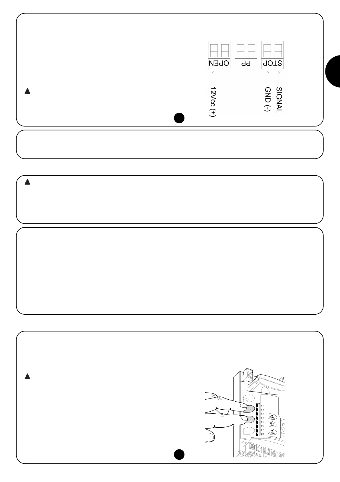
25
I
5.4) Collegare l'alimentazione elettrica
Per l'alimentazione elettrica a SOON è sufficiente inserire la sua spina in una presa di corrente. Eventualmente utilizzare un adattatore comunemente reperibile in commercio se la spina di SOON non corrisponde alla presa disponibile.
• Più dispositivi NC si possono collegare in serie tra di loro senza
alcun limite di quantità.
• Due dispositivi con uscita a resistenza costante 8,2KΩ si possono
collegare in parallelo; se vi sono più di 2 dispositivi allora tutti devono essere collegati “in cascata” con una sola resistenza di terminazione da 8,2KΩ.
• E' possibile la combinazione di NA ed NC ponendo i 2 contatti in
parallelo con l'avvertenza di porre in serie al contatto NC una resistenza da 8,2KΩ (ciò rende possibile anche la combinazione di 3
dispositivi: NA, NC e 8,2KΩ).
Se l'ingresso STOP è usato per collegare dispositivi con
funzioni di sicurezza; solo i dispositivi con uscita a resistenza costante 8,2KΩ o dispositivi ottici OPTO SENSOR
garantiscono la categoria 3 di sicurezza ai guasti secondo
la norma EN 954-1.
Per il collegamento di un dispositivo ottico tipo OPTO SENSOR eseguire, invece, le connessioni come in Fig. 9:
!
9
Le operazioni successive saranno effettuate su circuiti elettrici sotto tensione e le manovre potranno risultare pericolose! Operare quindi con attenzione e mai da soli.
Terminata l'installazione dei componenti ed effettuati i collegamenti elettrici, è necessario fare subito alcune semplici verifiche sul corretto funzionamento dell'impianto, prima di procedere oltre. Quindi, effettuare le operazioni elencate di seguito, barrando mano mano i punti dopo
aver verificato la conformità dei risultati.
!
6) Prima accensione dell'impianto - verifiche
7) Memorizzazione dispositivi e posizioni
6.1) Test di funzionamento
Non appena viene fornita tensione a SOON è consigliabile fare alcune semplici verifiche:
K Verificare che il led BlueBUS lampeggi regolarmente alla fre-
quenza di un lampeggio al secondo.
K Se presenti le fotocellule, verificare che lampeggino anche i led
sulle fotocellule (sia su TX che su RX); non è significativo il tipo
di lampeggio, dipende da altri fattori.
K Verificare che il dispositivo collegato all'uscita FLASH sia spento.
K Verificare che la luce di cortesia sia spenta.
Se tutto questo non avviene occorre spegnere immediatamente l'alimentazione alla centrale e controllare con maggiore attenzione i collegamenti elettrici.
7.1) Memorizzazione dispositivi
Dopo l'allacciamento dell'alimentazione occorre far riconoscere alla
centrale i dispositivi collegati sugli ingressi BlueBUS e STOP. Prima
di questa fase i led L1 ed L2 lampeggiano per indicare che occorre
eseguire l'apprendimento dei dispositivi.
La fase di apprendimento dei dispositivi deve essere
eseguita anche se non c'è nessun dispositivo collegato.
1. Premere e tenere premuti i tasti [▲] e [Set]
2. Rilasciare i tasti quando i led L1 e L2 iniziano a lampeggiare mol-
to velocemente (dopo circa 3s)
3. Attendere alcuni secondi che la centrale finisca l'apprendimento
dei dispositivi
Al termine dell'apprendimento il led STOP deve rimanere acceso, i
led L1 e L2 si spegneranno (eventualmente inizieranno a lampeggiare i led L3 e L4).
La fase di apprendimento dispositivi collegati può essere rifatta in
qualsiasi momento anche dopo l'installazione per esempio se venisse aggiunto un dispositivo.
!
10
Page 26

26
7.2) Memorizzazione delle posizioni
Dopo l'apprendimento dei dispositivi è necessario far riconoscere alla centrale le posizioni di apertura e chiusura del portone. È possibile programmare fino a 6 posizioni che sono:
Posizione Significato
A1 Quota di massima apertura che si desidera. Quando il portone arriva in questa posizione si ferma.
RA1 Quota di inizio rallentamento durante la manovra di apertura. Quando il portone arriva in questa posizione il motore
decelera portandosi alla velocità minima.
RINT Quota di rallentamento intermedio nella manovra di chiusura. Programmando questo punto il portone comincia a
decelerare circa 50cm prima, in modo da passare la posizione RINT a velocità minima. Passata la quota RINT il motore si
riporta alla velocità programmata.
AP Quota di apertura parziale. È la quota in cui il portone si arresta dopo aver dato un comando di apertura parziale.
RA0 Quota di inizio rallentamento durante la manovra di chiusura. Quando il portone arriva in questa posizione il motore
decelera portandosi alla velocità minima.
A0 Quota di massima chiusura. Quando il portone arriva in questa posizione si ferma.
Quando le quote non sono state acquisite lampeggiano i led L3 e L4.
Di seguito è descritta la procedura per la memorizzazione delle posizioni. Le quote A1 e A0 devono essere programmate mentre le altre
quote possono essere saltate. In quest'ultimo caso verranno calcolate automaticamente dalla centrale.
1. Premere [Set] + [▼] per 3 secondi per entrare in memorizzazione quote.
Lampeggia il led L1: programmazione quota A1
2. Con i tasti [▲] o [▼] spostare il portone nella posizione di apertura massima.
3. Premere il tasto [Set] per 2 secondi per confermare la quota A1. Il led L1 rimane acceso.
Lampeggia il led L2: programmazione quota RA1
4. Se non si vuole programmare la quota di rallentamento apertura, premere 2 volte velocemente il tasto [Set] per saltare alla
prossima programmazione, il led L2 rimane spento. Altrimenti proseguire con la sequenza.
5. Con i tasti [▲] o [▼] spostare il portone nella posizione di rallentamento apertura.
6. Premere il tasto [Set] per 2 secondi per confermare la quota RA1. Il led L2 rimane acceso.
Lampeggia il led L4: programmazione quota RINT
7. Se non si vuole programmare la quota di rallentamento intermedio, premere 2 volte velocemente il tasto [Set] per saltare alla
prossima programmazione, il led L4 rimane spento. Altrimenti proseguire con la sequenza.
8. Con i tasti [▲] o [▼] spostare il portone nella posizione di rallentamento intermedio.
9. Premere il tasto [Set] per 2 secondi per confermare la quota RINT. Il led L4 rimane acceso.
Lampeggia il led L5: programmazione quota RAP
10. Se non si vuole programmare la quota di apertura parziale, premere 2 volte velocemente il tasto [Set] per saltare alla prossima
programmazione, il led L5 rimane spento. Altrimenti proseguire con la sequenza.
11. Con i tasti [▲] o [▼] spostare il portone nella posizione di apertura parziale.
12. Premere il tasto [Set] per 2 secondi per confermare la quota RAP. Il led L5 rimane acceso.
Lampeggia il led L7: programmazione quota RA0
13. Se non si vuole programmare la quota di rallentamento chiusura, premere 2 volte velocemente il tasto [Set] per saltare alla
prossima programmazione, il led L7 rimane spento. Altrimenti proseguire con la sequenza.
14. Con i tasti [▲] o [▼] spostare il portone nella posizione di rallentamento chiusura.
15. Premere il tasto [Set] per 2 secondi per confermare la quota RA0. Il led L7 rimane acceso.
Lampeggia il led L8: programmazione quota A0
16. Con i tasti [▲] o [▼] spostare il portone nella posizione di chiusura massima.
17. Premere il tasto [Set] per 2 secondi per confermare la quota A0. led L8 rimane acceso.
18. Rilasciando il tasto [Set] si spengono tutti il led.
19. Dare un comando di apertura premendo il tasto [Open] per eseguire una manovra completa di apertura.
20. Dare un comando di chiusura premendo il tasto [Close] per eseguire una manovra completa di chiusura.
Durante queste manovre la centrale memorizza la forza necessaria
nei movimenti di apertura e chiusura.
E' importante che queste prime manovre non vengano interrotte, es. da un comando di STOP.
La fase di apprendimento delle posizioni può essere rifatta in qualsiasi momento anche dopo l'installazione; basta ripeterla dal punto
1. Se invece è necessario modificare una sola quota ripetere la
sequenza dal punto 1 e saltare la programmazione delle quote non
interessate premendo 2 volte velocemente il tasto [Set] per ogni
posizione da saltare.
11
Page 27
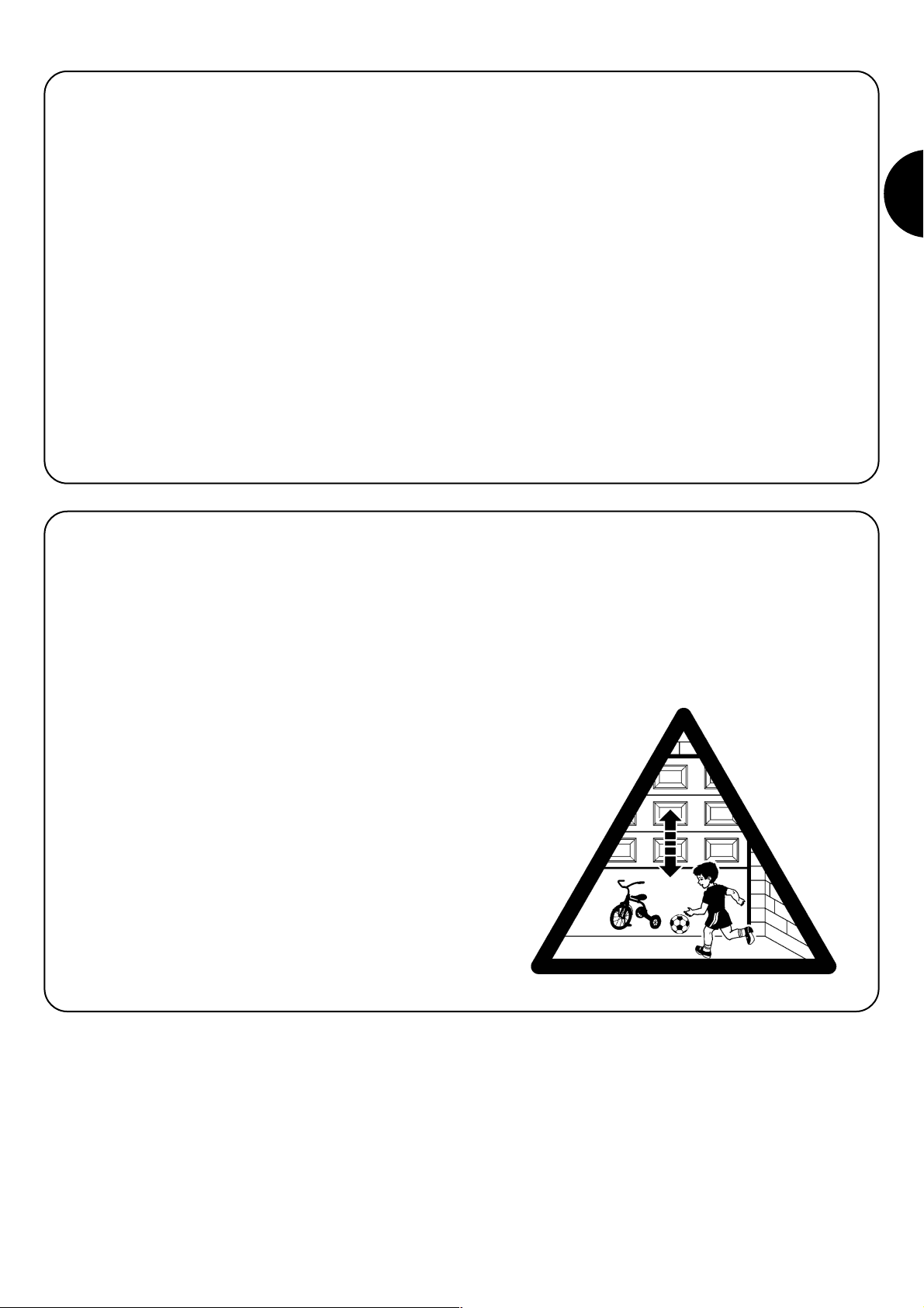
27
I
8) Effettuare il collaudo finale dell'impianto
8.1) Test per il collaudo finale
Ogni singolo componente dell'automatismo, ad esempio
bordi sensibili, fotocellule, arresto di emergenza, ecc. richiede una specifica fase di collaudo; per questi dispositivi si dovranno eseguire le procedure riportate nei rispettivi manuali istruzioni. Per il collaudo di SOON eseguire la
seguente sequenza di operazioni:
1. Verificare che si sia rispettato rigorosamente quanto previsto nel
capitolo 1 “AVVERTENZE”.
2. Sbloccare il portone dal motore tirando il cordino di sblocco verso il basso. Verificare che sia possibile muovere manualmente il
portone in apertura e in chiusura con una forza non superiore a
225N.
3. Bloccare il portone al motore tirando manualmente il cordino di
blocco.
4. Utilizzando il selettore o il trasmettitore radio, effettuare delle prove di chiusura e apertura del portone e verificare che il movimento corrisponda a quanto previsto.
5. Conviene eseguire diverse prove al fine di valutare la scorrevolezza del portone ed eventuali difetti di montaggio o regolazione
nonché la presenza di particolari punti d'attrito.
6. Verificare uno ad uno il corretto funzionamento di tutti i dispositivi di sicurezza presenti nell'impianto (fotocellule, bordi sensibili
ecc.). In particolare, ogni volta che un dispositivo interviene il led
“BlueBUS” sulla centrale esegue 2 lampeggi più veloci a conferma che la centrale riconosce l'evento.
7. Per verificare il funzionamento delle fotocellule ed in particolare
che non vi siano interferenze con altri dispositivi, passare un cilindro di diametro 5cm e lunghezza 30 cm sull'asse ottico prima
vicino al TX, poi vicino all'RX e infine al centro tra i due e verificare che in tutti i casi il dispositivo intervenga passando dallo
stato di attivo a quello di allarme e viceversa; infine che provochi
nella centrale l'azione prevista; esempio: nella manovra di chiusura provoca l'inversione di movimento.
8. Se le situazioni pericolose provocate dal movimento del portone
sono state salvaguardate mediante la limitazione della forza
d'impatto si deve eseguire la misura della forza secondo quanto
previsto dalla norma EN 12445. Se la regolazione della “Velocità”
ed il controllo della “Forza Motore” vengono usati come ausilio al
sistema per la riduzione della forza d'impatto, provare e trovare
le regolazione che offrono i migliori risultati.
8.2) Messa in servizio
La messa in servizio può avvenire solo dopo aver eseguito con esito positivo tutte le fasi di collaudo di Soon e degli altri dispositivi presenti. E' vietata la messa in servizio
parziale o in situazioni “provvisorie”.
1. Realizzare e conservare per almeno 10 anni il fascicolo tecnico
dell'automazione che dovrà comprendere almeno: disegno
complessivo dell'automazione, schema dei collegamenti elettrici,
analisi dei rischi e relative soluzioni adottate, dichiarazione di
conformità del fabbricante di tutti i dispositivi utilizzati (per Soon
utilizzare la Dichiarazione CE di conformità allegata); copia del
manuale di istruzioni per l'uso e del piano di manutenzione dell'automazione.
2. Apporre sul portone una targhetta contenente almeno i seguenti dati: tipo di automazione, nome e indirizzo del costruttore
(responsabile della “messa in servizio”), numero di matricola,
anno di costruzione e marchio “CE”.
3. Fissare in maniera permanente in prossimità del portone un'etichetta o una targa con indicate le operazioni per lo sblocco e la
manovra manuale
4. Fissare in maniera permanente sul portone una etichetta o targa
con questa immagine (altezza minima 60mm).
5. Realizzare e consegnare al proprietario la dichiarazione di
conformità dell'automazione.
6. Realizzare e consegnare al proprietario il manuale di “Istruzioni
ed avvertenze per l'uso dell'automazione”.
7. Realizzare e consegnare al proprietario il piano di manutenzione
dell'automazione (che deve raccogliere tutte le prescrizioni sulla
manutenzione dei singoli dispositivi).
8. Prima di mettere in servizio l'automatismo informare adeguatamente ed in forma scritta il proprietario (ad esempio sul manuale di istruzioni ed avvertenze per l'uso dell'automazione) sui pericoli ed i rischi ancora presenti.
Page 28
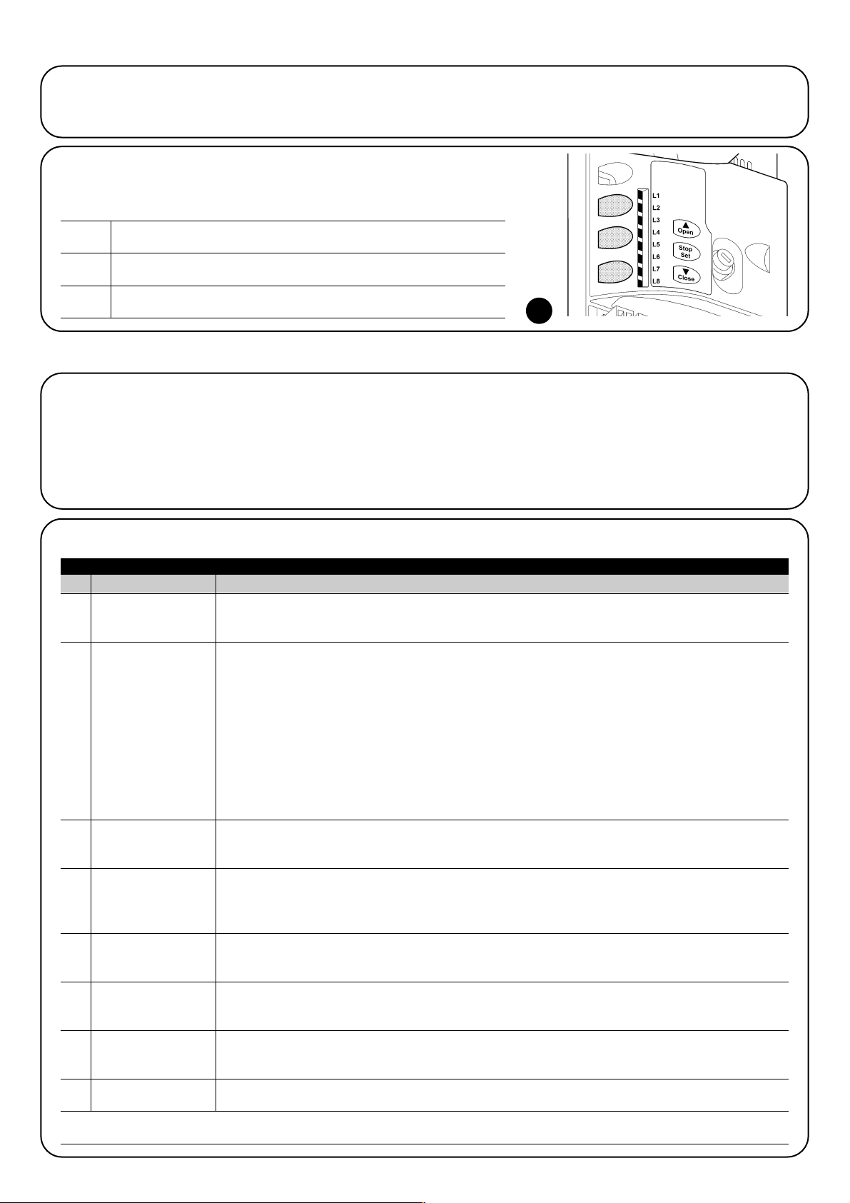
28
Questa SECONDA PARTE descrive come personalizzare il funzionamento dell'automazione, attraverso regolazioni e opzioni da memorizzare nella memoria della Centrale. Una sezione finale è dedicata invece alla risoluzione dei problemi, alla manutenzione e allo smaltimento del
prodotto.
9) Istruzioni per personalizzare il funzionamento dell'automazione
Sulla centrale di controllo di SOON sono disponibili alcune funzioni
programmabili; la regolazione delle funzioni avviene attraverso 3 tasti
presenti sulla centrale: [▲] [Set] [▼] e vengono visualizzate attraverso 8 led: L1….L8.
Le funzioni programmabili disponibili su SOON sono disposte su 2
livelli:
Primo livello: funzioni regolabili in modo ON-OFF (attivo oppure
non attivo); in questo caso ogni led L1….L8 indica una funzione, se
acceso la funzione è attiva, se spento la funzione non è attiva; vedere Tab. 3.
Secondo livello: parametri regolabili su una scala di valori (valori
da 1 a 8); in questo caso ogni led L1….L8 indica il valore regolato
tra i 8 possibili; vedere Tab. 4.
10) Programmazioni
Il tasto “OPEN” permette di comandare l'apertura del portone oppure di
spostare verso l'alto il punto di programmazione
Il tasto “STOP” permette di fermare la manovra se premuto per più di 5
secondi permette di entrare in programmazione.
Il tasto “CLOSE “permette di comandare la chiusura del portone oppure di
spostare verso il basso il punto di programmazione
9.1) Tasti di programmazione
Sulla centrale di controllo di SOON sono presenti 3 tasti che possono essere usati sia
per il comando della centrale durante le prove sia per le programmazioni:
12
OPEN
▲
STOP
SET
CLOSE
▼
Led Funzione Descrizione
L1 Chiusura Automatica Questa funzione permette una chiusura automatica del cancello dopo il tempo pausa programmato, di
fabbrica il Tempo Pausa è posto a 30 secondi ma può essere modificato a 10, 20, 40, 60, 80, 120, 160 e
200 secondi. Se la funzione non è attivata, il funzionamento è “semiautomatico”.
L2 Richiudi Dopo Foto Questa funzione permette di tenere il portone aperto solo per il tempo necessario al transito, infatti l'intervento di
"Foto" provoca sempre una richiusura automatica con un tempo pausa di 5s (indipendentemente dal valore
programmato). Il comportamento cambia a seconda che sia attiva o meno la funzione di "Chiusura Automatica".
Con "Chiusura Automatica" non attiva: Il portone raggiunge sempre la posizione di totale apertura
(anche se il disimpegno di Foto avviene prima). Al disimpegno di Foto si provoca la richiusura automatica
con una pausa di 5s.
Con "Chiusura Automatica" attiva: la manovra di apertura si arresta subito dopo il disimpegno delle
fotocellule e si provoca la richiusura automatica con una pausa di 5s.
La funzione di "Richiudi Dopo Foto" viene sempre disabilitata nelle manovre interrotte con un comando di
Stop. Se la funzione "Richiudi Dopo Foto" non è attiva il tempo di pausa sarà quello programmato o non ci
sarà richiusura automatica se la funzione non è attiva.
L3 Chiude Sempre La funzione “Chiude Sempre” interviene, provocando una chiusura, quando al ritorno dell'alimentazione
viene rilevato il portone aperto. Per questioni di sicurezza la manovra viene preceduta da 3s di
prelampeggio. Se la funzione non è attiva, al ritorno dell'alimentazione il portone rimarrà fermo.
L4 Stand-By Questa funzione permette di ridurre al massimo i consumi. Se questa funzione è attiva, dopo 1 minuto dal
termine della manovra, la centrale spegne l'uscita BlueBUS (e quindi i dispositivi) e tutti i led ad esclusione
del led BlueBUS che lampeggerà più lentamente. Quando la centrale riceve un comando ripristina il pieno
funzionamento. Se la funzione non è attiva non ci sarà riduzione dei consumi.
L5 Inversione lunga Questa funzione permette di selezione il tipo inversione che il portone esegue a causa dell'intervento di
STOP o del limitatore di forza. Se la funzione non è attiva l'inversione è breve (15cm circa). Se la funzione è
attiva l'inversione avviene fino alla quota di apertura o chiusura massima.
L6 Prelampeggio Con la funzione di prelampeggio viene aggiunta una pausa di 3s tra l'accensione del lampeggiante e l'inizio
della manovra per avvertire in anticipo della situazione di pericolo. Se il prelampeggio non è attivo
l'accensione del lampeggiante coincide con l'inizio manovra.
L7 Sensibilità Questa funzione permette di aumentare notevolmente la sensibilità del motore nella rilevazione ostacoli. Se
viene utilizzata come ausilio per la rilevazione della forza d'impatto regolare anche i parametri “Velocità” e
“Forza motore” nel menù di secondo livello.
L8 Compensazione Questa funzione permette di recuperare l'allungamento nel tempo delle funi metalliche del portone ed è
subordinata all'impiego di un bordo sensibile ti tipo resistivo 8,2KΩ oppure ottico OSE.
Durante il funzionamento normale di SOON, quando non è in corso nessuna manovra, i led L1….L8 sono accesi o spenti in base allo stato della funzione che rappresentano, ad esempio L1 è acceso se è attiva la “Chiusura automatica”.
Tabella 3: elenco funzioni programmabili: primo livello
10.1) Funzioni primo livello
Page 29
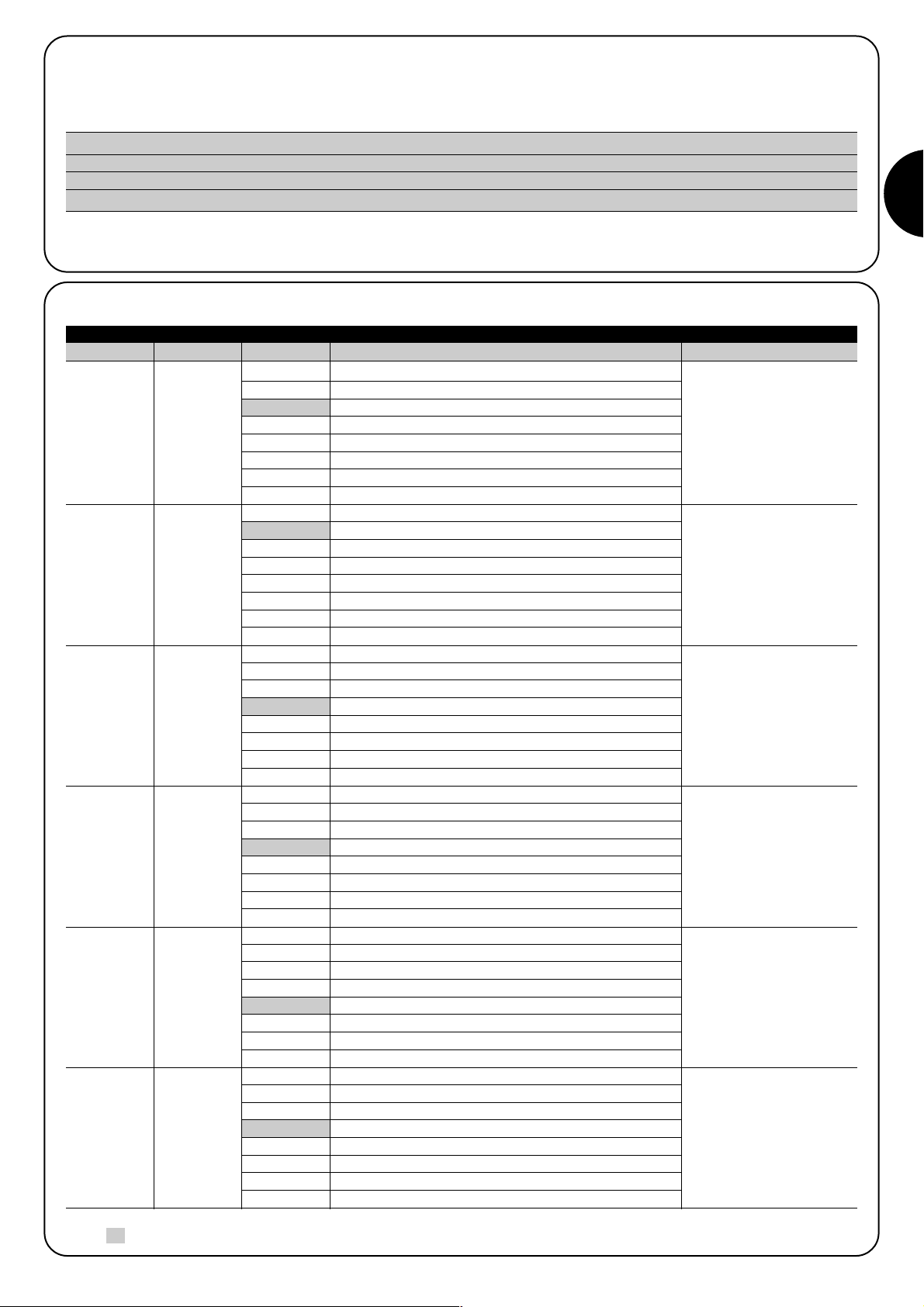
29
I
Tempo
Pausa
Funzione P.P.
Velocità
Motore
Uscita
FLASH
Forza motore
in apertura
Forza motore
in chiusura
L1
L2
L3
L4
L5
L6
L7
L8
L1
L2
L3
L4
L5
L6
L7
L8
L1
L2
L3
L4
L5
L6
L7
L8
L1
L2
L3
L4
L5
L6
L7
L8
L1
L2
L3
L4
L5
L6
L7
L8
L1
L2
L3
L4
L5
L6
L7
L8
10 secondi
20 secondi
40 secondi
60 secondi
80 secondi
120 secondi
160 secondi
200 secondi
Apre - stop - chiude - stop
Apre - stop - chiude- apre
Apre - chiude - apre - chiude
Condominiale
Condominiale 2 (più di 2” fa stop)
Passo-Passo 2 (meno di 2” fa apre parziale)
Uomo presente
Apertura in “semiautomatico”, chiusura a “uomo presente”
Velocità 1 (30% - lenta)
Velocità 2 (44%)
Velocità 3 (58%)
Velocità 4 (72%)
Velocità 5 (86%)
Velocità 6 (100% - veloce)
Apre V4, chiude V2
Apre V6, chiude V4
Spia Portone Aperto
Attiva se portone chiuso
Attiva se portone aperto
Lampeggiante
Elettroblocco
Elettroserratura
Ventosa
Spia Manutenzione
Forza 1 (bassa)
Forza 2
Forza 3
Forza 4
Forza 5
Forza 6
Forza 7
Forza8 (alta)
Forza 1 (bassa)
Forza 2
Forza 3
Forza 4
Forza 5
Forza 6
Forza 7
Forza8 (alta)
10.3) Funzioni secondo livello (parametri regolabili)
Tabella 4: elenco funzioni programmabili: secondo livello
Led di entrata
Parametro Led (livello) Valore Descrizione
Regola il tempo di pausa
cioè il tempo prima della
richiusura automatica. Ha
effetto solo se la chiusura
automatica è attiva.
Regola la sequenza di
comandi associati
all'ingresso PPoppure al 1°
comando radio.
Regola la velocità del
motore durante la corsa
normale.
Seleziona il dispositivo
collegato all'uscita FLASH.
Regola il sistema di
controllo della forza del
motore per adeguarlo al
peso del portone durante la
manovra di apertura.
Regola il sistema di
controllo della forza del
motore per adeguarlo al
peso del portone durante la
manovra di chiusura.
Nota: “ ” rappresenta la regolazione di fabbrica SEGUE
L1
L2
L3
L4
L5
L6
10.2) Programmazioni primo livello
Di fabbrica le funzioni del primo livello sono poste tutte “OFF” ma si possono cambiare in qualsiasi momento come descritto di seguito. Fare
attenzione nell'eseguire la procedura perché c'è un tempo massimo di 10s tra la pressione di un tasto e l'altro, altrimenti la procedura finisce automaticamente memorizzando le modifiche fatte fino a quel momento.
Attendere 10s per uscire dalla programmazione per fine tempo massimo.
Nota: i punti 3 e 4 possono essere ripetuti durante le stessa fase di programmazione per porre ON o OFF altre funzioni
1. Premere e tener premuto il tasto [Set] per circa 3s
2. Rilasciare il tasto [Set] quando il led L1 inizia a lampeggiare
3. Premere i tasti [▲] o [▼] per spostare il led lampeggiante sul led che rappresenta la funzione da modificare
4. Premere il tasto [Set] per cambiare lo stato della funzione (lampeggio breve = OFF; lampeggio lungo = ON)
Page 30
30
SOON consente di avvisare l'utente quando eseguire un
controllo di manutenzione dell'automazione. Il numero di
manovre dopo il quale avviene la segnalazione è selezionabile tra 8 livelli, mediante il parametro regolabile “Avviso di manutenzione” (vedere Tab. 4).
Il livello 1 di regolazione è “automatico” e tiene conto della gravosità delle manovre, cioè dello sforzo e della durata della manovra, mentre le altre
regolazioni sono fissate in base al numero delle manovre.
La segnalazione di richiesta di manutenzione avviene attraverso il lampeggiante o la Spia di manutenzione a seconda della programmazione
(vedere Tab. 4).
In base al numero di manovre eseguite rispetto al limite programmato il
lampeggiante Flash e la spia manutenzione danno le segnalazioni riportate in Tab. 5.
11) Avviso di manutenzione
Avviso di
manutenzione
Elenco
anamalie
L1
L2
L3
L4
L5
L6
L7
L8
L1
L2
L3
L4
L5
L6
L7
L8
Automatico (in base alla gravosità delle manovre)
1.000
2.000
4.000
6.000
8.000
10.000
12.000
Esito 1amanovra (la più recente)
Esito 2amanovra
Esito 3amanovra
Esito 4amanovra
Esito 5amanovra
Esito 6amanovra
Esito 7amanovra
Esito 8
a
manovra
Led di entrata
Parametro Led (livello) Valore Descrizione
Regola il numero di
manovre dopo il quale
segnalare la richiesta di
manutenzione
dell'automazione (vedere
paragrafo “13 Avviso di
Manutenzione”).
Permette di verificare il tipo
di anomalia intervenuta
nelle ultime 8 manovre
(vedere paragrafo “14
Elenco storico anomalie”)
Nota: “ ” rappresenta la regolazione di fabbrica
Tutti i parametri possono essere regolati a piacere senza nessuna controindicazione; solo le regolazioni di “Forza motore in apertura” “Forza
motore in chiusura” potrebbero richiedere una attenzione particolare:
• E' sconsigliato utilizzare valori alti di forza per compensare il fatto che l'anta abbia dei punti di attrito anomali; una forza eccessiva può pre-
giudicare il funzionamento del sistema di sicurezza o danneggiare l'anta.
• Se il controllo della “Forza motore” viene usato come ausilio al sistema per la riduzione della forza di impatto, dopo ogni regolazione ripe-
tere la misura della forza, come previsto dalla norma EN 12445.
• L'usura e le condizioni atmosferiche influiscono sul movimento del portone, periodicamente e necessario ricontrollare la regolazione della
forza.
L7
L8
10.4) Programmazioni secondo livello
Di fabbrica i parametri regolabili sono posti come evidenziato in Tab. 4 con: “ ” ma si possono cambiare in qualsiasi momento come
descritto di seguito. Fare attenzione nell'eseguire la procedura perché c'è un tempo massimo di 10s tra la pressione di un tasto e l'altro, altrimenti la procedura finisce automaticamente memorizzando le modifiche fatte fino a quel momento
Attendere 10s per uscire dalla programmazione per fine tempo massimo.
Nota: i punti da 3 a 7 possono essere ripetuti durante le stessa fase di programmazione per regolare più parametri.
1. Premere e tener premuto il tasto [Set] per circa 3s
2. Rilasciare il tasto [Set] quando il led L1 inizia a lampeggiare
3. Premere i tasti [▲] o [▼] per spostare il led lampeggiante sul “led di entrata” che rappresenta il parametro da modificare
4. Premere e mantenere premuto il tasto [Set], il tasto [Set] va mantenuto premuto durante tutti i passi 5 e 6
5. Attendere circa 3s dopodiché si accenderà il led che rappresenta il livello attuale del parametro da modificare
6. Premere i tasti [▲] o [▼] per spostare il led che rappresenta il valore del parametro.
7. Rilasciare il tasto [Set]
Numero manovre Segnalazione su Flash Segnalazione su spia manutenzione
Inferiore a 80% del limite Normale (0.5s acceso, 0.5s spento) Accesa per 2s ad inizio apertura
Tra 81 e 100% del limite A inizio manovra rimane acceso per Lampeggia durante tutta la manovra
2s poi prosegue normalmente
Oltre il 100% del limite Ad inizio e fine manovra rimane acceso per 2s poi prosegue Lampeggia sempre.
normalmente
Tabella 5: avviso di manutenzione con Flash e spia manutenzione
Page 31

31
I
11.1) Verifica del numero di manovre effettuate
Con la funzione di “Avviso di manutenzione” è possibile verificare il numero di manovre eseguite in percentuale sul limite impostato. Per la
verifica procedere come descritto di seguito.
1. Premere e tener premuto il tasto [Set] per circa 3s
2. Rilasciare il tasto [Set] quando il led L1 inizia a lampeggiare
3. Premere i tasti [▲] o [▼] per spostare il led lampeggiante sul L7, cioè il “led di entrata” per il parametro “Avviso si manutenzione”
4. Premere e mantenere premuto il tasto [Set], il tasto [Set] va mantenuto premuto durante tutti i passi 5, 6 e 7
5. Attendere circa 3s dopodiché si accenderà il led che rappresenta il livello attuale del parametro “Avviso si manutenzione”
6. Premere e subito rilasciare i tasti [▲] e [▼].
7. Il led corrispondente al livello selezionato farà alcuni lampeggi. Il numero di lampeggi identifica la percentuale di manovre effettuate
(in multipli di 10%) rispetto al limite impostato. Ad esempio: con impostato l'avviso di manutenzine su L7 cioè 10000, il 10%
corrisponde a 1000 manovre; se il led di visualizzazione fa 4 lampeggi, significa che è stato raggiunto il 40% delle manovre (cioè tra
4000 e 4999 manovre). Se non è stato raggiunto il 10% delle manovre non ci sarà nessun lampeggio.
8. Rilasciare il tasto [Set].
SOON permette di visualizzare le eventuali anomalie che si sono verificate nelle ultime 8 manovre, ad esempio l'interruzione di una manovra
per l'intervento di una fotocellula o di un bordo sensibile. Per verificare l'elenco delle anomalie precedere descritto di seguito.
1. Premere e tener premuto il tasto [Set] per circa 3s
2. Rilasciare il tasto [Set] quando il led L1 inizia a lampeggiare
3. Premere i tasti [▲] o [▼] per spostare il led lampeggiante sul L8, cioè il “led di entrata” per il parametro “Elenco anomalie”
4. Premere e mantenere premuto il tasto [Set], il tasto [Set] va mantenuto premuto durante tutti i passi 5 e 6
5. Attendere circa 3s dopodiché si accenderanno i led corrispondenti alle manovre che hanno avuto delle anomalie.
Il led L1 indica l'esito della manovra più recente,il led L8 indica l'esito dell'ottava Se il led è acceso significa che durante la manovra
si sono verificate delle anomalie; se il led è spento significa che la manovra è terminata senza anomalie.
6. Premere i tasti i tasti [▲] e [▼] per selezionare la manovra desiderata: il led corrispondente farà un numero di lampeggi pari a quelli
normalmente eseguiti dal lampeggiante dopo un'anomalia.
7. Rilasciare il tasto [Set].
11.2) Azzeramento contatore manovre
Dopo aver eseguito la manutenzione dell'impianto è necessario azzerare il contatore delle manovre. Procedere come descritto.
1. Premere e tener premuto il tasto [Set] per circa 3s
2. Rilasciare il tasto [Set] quando il led L1 inizia a lampeggiare
3. Premere i tasti [▲] o [▼] per spostare il led lampeggiante sul L7, cioè il “led di entrata” per il parametro “Avviso si manutenzione”
4. Premere e mantenere premuto il tasto [Set], il tasto [Set] va mantenuto premuto durante tutti i passi 5 e 6
5. Attendere circa 3s dopodiché si accenderà il led che rappresenta il livello attuale del parametro “Avviso si manutenzione”
6. Premere e tenere premuto per almeno 5 secondi i tasti [▲] e [▼], quindi rilasciare i 2 tasti. Il led corrispondente al livello
selezionato eseguirà una serie di lampeggi veloci per segnalare che il contatore delle manovre è stato azzerato.
7. Rilasciare il tasto [Set].
Se vi fosse l'esigenza di alimentare dispositivi esterni ad esempio un
lettore di prossimità per tessere a transponder oppure la luce d'illuminazione del selettore a chiave è possibile prelevare l'alimentazione
come indicato in figura 12. La tensione di alimentazione è 24Vcc 30% ÷ +50% con corrente massima disponibile di 100mA.
13) Collegamento altri dispositivi
12) Elenco storico anomalie
12
Page 32

32
14) Approfondimenti: funzioni particolari
14.1) Funzione “Apri sempre”
La funzione “Apri sempre” è una proprietà della centrale di controllo che permette di comandare sempre una manovra di apertura quando il
comando di “Passo-Passo” ha una durata superiore a 2 secondi; ciò è utile ad esempio per collegare al morsetto PP il contatto di un orologio programmatore per mantenere aperto il cancello per una certa fascia oraria. Questa proprietà è valida qualunque sia la programmazione
dell'ingresso di PP ad esclusione della programmazione come “Condominiale 2”, vedere parametro “Funzione PP” in Tab. 4.
15) Funzionamento dell’automazione tramite trasmettitore e ricevitore-radio con innesto tipo “SM”
Sulla Centrale è presente un connettore dedicato all'installazione di
un Ricevitoreradio con innesto tipo “SM" (Fig. 13), per comandare
l'automazione con un Trasmettitore-radio (ricevitore e trasmettitore
sono accessori opzionali). Le quattro Uscite del Ricevitore permettono di dare alla Centrale i seguenti comandi:
Se non viene utilizzata l'antenna incorporata a LUCYB o altro tipo di
antenna esterna, avvitare il cavetto rigido in dotazione al ricevitore al
morsetto dell'antenna (Fig. 14).
14.2) Funzione “Muovi comunque”
Nel caso in cui qualche dispositivo di sicurezza non dovesse funzionare correttamente o fosse fuori uso, è possibile comunque comandare
e muovere il cancello in modalità “Uomo presente”. Per i dettagli vedere il paragrafo “Comando con sicurezze fuori uso” presente nell'allegato “Istruzioni ed avvertenze destinate all'utilizzatore del motoriduttore SOON”.
Uscita N°1 Comando “P.P.” (Passo-Passo)
Uscita N°2 Comando “Apertura parziale”
Uscita N°3 Comando “Apre”
Uscita N°4 Comando “Chiude”
Tabella 6: comandi con ricevitore SMXI, SMXIS
16) Controllo e diagnosi automatica delle anomalie di funzionamento
Durante il regolare funzionamento, la Centrale tiene costantemente sotto controllo i processi dell'automazione ed è in grado di segnalare
eventuali anomalie, attraverso preordinate sequenze di lampeggi emesse dal lampeggiante, luce di cortesia e “Led BlueBUS” (i lampeggi diagnostici si riferiscono sempre all'ultima azione compiuta da Soon). Per comprendere la corrispondenza fra numero dei lampeggi e cause, fare
riferimento alla seguente tabella:
Tabella 7: lampeggi di diagnostica
13 14
n° lamp causa
1 Errore sincronizzazione BlueBUS
2 Intervento di Foto o errore del Fototest
3 Forza del motoriduttore non sufficiente oppure rilevato ostacolo durante la corsa
4 Intervento dei dispositivi di Stop
5 Errore sui parametri della memoria
6 Intervento limitatore manovre interno
7 Mancanza corrente nei circuiti motore
8 Sovracorrente nei circuiti motore
Page 33

33
I
17) Cosa fare se… (Guida alla risoluzione dei problemi)
Questa è una piccola guida alla risoluzione dei problemi più comuni
che si possono presentare durante l'installazione e la programmazione dell'automazione.
•
…non si comanda nessuna manovra ed il led “Blue-BUS”
non lampeggia
- Verificare che Soon sia alimentato con la tensione di rete 230V.
Verificare che i fusibili F1 e F2 (Fig. 15) non siano interrotti; in questo caso, verificare la causa del guasto e poi sostituirli con altri dello stesso valore di corrente e caratteristiche.
•
…non si comanda nessuna manovra ed il lampeggiante è
spento
- Verificare che il comando venga effettivamente ricevuto. Se il
comando giunge sull'ingresso PP il relativo led “PP” deve accendersi; se invece viene utilizzato il trasmettitore radio, il led “BlueBUS” deve fare due lampeggi veloci.
• …
la manovra non parte e la luce di cortesia fa alcuni
lampeggi
Contare il numero di lampeggi e verificare secondo quanto riportato in Tab. 7.
• …
durante la manovra viene eseguita una breve inver-
sione
- La forza selezionata potrebbe essere troppo bassa per muovere il
portone. Verificare se ci sono degli ostacoli ed eventualmente selezionare una forza superiore.
- Verificare se è intervenuto un dispositivo di sicurezza collegato
all'ingresso di Stop.
• …
la manovra viene eseguita ma il dispositivo collegato
all'uscita FLASH non funziona
- Verificare che il dispositivo collegato all'uscita “FLASH” sia effettivamente quello programmato.
- Verificare che quando il dispositivo dovrebbe essere alimentato ci
sia tensione sul morsetto del dispositivo; se c'è tensione, il problema è dovuto al dispositivo che dovrà essere sostituito con uno di
uguali caratteristiche. Se non c'è tensione significa che che c'è un
sovraccarico elettrico sull'uscita. Verificare che non vi sia cortocircuito sul cavo.
•
…durante la fase di memorizzazione quote lampeggiano
velocemente il led L1 oppure il led L8
- Significa che è stata raggiunta la quota di extracorsa alta (lampeggia velocemente L1) o bassa (lampeggia velocemente L8).
- Se lampeggia il led L1 eseguire una manovra di chiusura fino a
quando L1 smette di lampeggiare velocemente. Quindi disinstallare Soon dall'albero portamolle, aprire il portone nella posizione
massima e reinstallare Soon da questa posizione.
- Se lampeggia il led L8 eseguire una manovra di apertura fino a
quando L8 smette di lampeggiare velocemente. Quindi disinstallare Soon dall'albero portamolle, chiudere il portone nella posizione
massima e reinstallare Soon da questa posizione.
15
Come per le operazioni d'installazione, anche al termine della vita di
questo prodotto, le operazioni di smantellamento devono essere
eseguite da Personale Tecnico qualificato.
Questo prodotto è costituito da vari tipi di materiali: alcuni possono
essere riciclati, altri devono essere smaltiti. Informatevi sui sistemi di
riciclaggio o smaltimento previsti dai Regolamenti vigenti nel vostro
territorio, per questa categoria di prodotto.
Alcune parti del prodotto possono contenere sostanze
inquinanti o pericolose, se disperse potrebbero provocare
effetti dannosi sull'ambiente e sulla salute umana.
Come indicato dal simbolo di Figura 16 è vietato gettare questo prodotto nei rifiuti domestici. Eseguire la “raccolta separata” per lo smaltimento secondo i metodi previsti dai regolamenti locali; oppure
riconsegnare il prodotto al venditore nel momento dell'acquisto di un
nuovo prodotto equivalente.
I Regolamenti locali possono prevedere pesanti sanzio-
ni in caso di smaltimento abusivo di questo prodotto.
!
!
16
18) Smaltimento
Page 34

34
Soon
Sommaire page
Instructions pour installer et mettre en marche
l'automatisme 35
1 Opérer en conditions de sécurité 35
1.1 Précautions et consignes de sécurité 35
2 Connaître les caractéristiques du produit 35
2.1 Description du produit, application et
caractéristiques techniques 35
3 Évaluer la faisabilité de l'installation 36
3.1 Vérifier les composants du produit 36
3.2 Vérifier que l'environnement est adapté 36
3.3 Vérifier les limites d'utilisation du produit 36
4 Installer les différents composants 36
4.1 Schéma typique d'installation 36
4.2 Installer les composants mécaniques 37
4.3 Pose des câbles électriques 38
4.4
Procédure manuelle d'embrayage et de débrayage
38
5 Effectuer les connexions électriques 38
5.1 Connecter tous les dispositifs 38
5.2 Connecter les dispositifs BlueBUS 40
5.2.1 Photocellules 40
5.2.2 Photodétecteur FT210B 40
5.3 Connecter les dispositifs à l'entrée STOP 40
5.4 Connecter l'alimentation électrique 41
6 Premier allumage de l'installation - vérifications 41
6.1 Test de fonctionnement 41
7 Mémorisation dispositifs et positions 41
7.1 Mémorisation dispositifs 41
7.2 Mémorisation des positions 42
8 Effectuer l'essai final de l'installation 43
8.1 Test pour l'essai final 43
8.2 Mise en service 43
INTRODUCTION
Cette notice explique comment installer, programmer et utiliser l'automatisme Soon pour porte sectionnelle. Les différents points sont subdivisés en trois parties distinctes:
La PREMIÈRE PARTIE est un guide pas à pas qui illustre les
phases nécessaires à l'installation « physique » du produit et
à sa mise en service.
La DEUXIÈME PARTIE décrit comment personnaliser le fonctionnement de Soon, à travers la programmation de certaines
fonctions spécifiques et le choix d'options et de réglages particuliers. De plus, une section est dédiée à la maintenance et
à la mise au rebut du produit.
La Première et la Deuxième Partie de la notice sont destinées
exclusivement au Personnel Technique qualifié qui installera l'automatisme. Aucune de ces informations ne peut être considérée comme utile ou
intéressante pour l'utilisateur final du produit.
!
9 Instructions pour personnaliser le fonctionnement
de l'automatisme 44
9.1 Touches de programmation 44
10 Programmations 44
10.1 Fonctions premier niveau 44
10.2 Fonctions premier niveau 45
10.3 Fonctions deuxième niveau (paramètres réglables) 45
10.4 Programmations deuxième niveau 46
11 Avis de maintenance 46
11.1 Vérification du nombre de manœuvres effectuées 47
11.2 Mise à zéro du compteur des manœuvres 47
12 Liste historique des anomalies 47
13 Connexion d'autres dispositifs 47
14 Approfondissements: fonctions particulières 48
14.1 Fonction « Ouvre toujours » 48
14.2 Fonction « Manœuvre dans tous les cas » 48
15 Fonctionnement de l'automatisme avec
émetteur et récepteur-radio « SM » 48
16 Contrôle et diagnostic automatique des
anomalies de fonctionnement 48
17 Que faire si…
(Guide à la résolution des problèmes) 49
18 Mise au rebut 49
Page 35

35
F
Instructions pour l'installation et la mise en marche de l'automatisme
Cette PREMIÈRE PARTIE décrit pas à pas toutes les phases de l'installation du produit (montage mécanique, connexions électriques, essai) et
de sa première mise en marche (paramétrages de fonctionnement).
Ces phases sont précédées d'indications très importantes concernant la
sécurité, les caractéristiques du produit et la faisabilité de l'installation.
1.1) Precauzioni e avvertenze per la sicurezza
Les opérations d'installation, de programmation et de mise en
service du produit doivent être effectuées uniquement par du personnel techniquement qualifié, conformément aux lois et normes en
vigueur en la matière et aux instructions contenues dans cette notice.
La présente notice est structurée pour guider pas à pas le travail
d'installation, de programmation et de mise en service de l'opérateur
Soon. Toutes les opérations à effectuer, avec les instructions nécessaires, sont reportées dans l'ordre précis dans lequel les phases de
travail devront être effectuées.
Il est donc important de lire toutes les sections de la notice avant de
commencer le travail d'installation. Nous recommandons en particulier de lire très attentivement les sections qui contiennent des informations fondamentales pour la SÉCURITÉ comme la présente Section 1, la Section 3 - VÉRIFICATIONS AVANT L'INSTALLATION ET
LIMITES D'UTILISATION DU PRODUIT et la Section 8 - ESSAI ET
MISE EN SERVICE DU SYSTÈME.
Compte tenu des dangers qui peuvent se vérifier durant l'installation
et l'utilisation quotidienne du produit, il faut que l'installation soit faite dans le plein respect de la Directive Européenne n° 98/37/CE
(Directive Machines réglementant la réalisa-tion d'une porte ou d'un
portail automatique) et en particulier des normes EN 12445, EN
12453 et EN 12635.
Le respect de cette Directive vous permet d'opérer avec le maximum de sécurité, d'émettre à la fin du travail la déclaration de
conformité présumée et donc, de garantir la sécurité de l'installation.
NOTE: D'autres informations et les conseils pour l'analyse des
risques, utiles pour la réalisation du “Dossier Technique”, sont disponibles sur le site internet: www.niceforyou.com.
• Une utilisation du produit Soon différente des applications illus-
trées dans cette notice est interdite. Des utilisations impropres
peuvent endommager le produit et mettre en danger les personnes et les choses.
• Toute modification d'un composant quelconque du produit est
interdite à l'exclusion de celles qui sont expressément indiquées
dans la notice. Les opérations non autorisées ne peuvent qu'entraîner des problèmes de fonctionnement et Nice
®
décline toute
responsabilité pour les dommages dérivant de produits modifiés
arbitrairement.
• Avant de commencer l'installation, il faut effectuer l'analyse des
risques comprenant la liste des exigences essentielles de sécurité
requises par l'annexe I de la Directive Machines, en indiquant les
solutions adoptées. Nous rappelons que l'analyse des risques est
l'un des documents qui constituent le “Dossier technique” de l'automatisation.
• Avant de commencer l'installation, il est bon de vérifier la nécessité
d'autres dispositifs et matériels qui peuvent servir à compléter l'automatisation avec Soon en évaluant les conditions spécifiques de
l'application et les risques présents; il faut considérer par exemple
les risques d'impact, écrasement, cisaillement, coincement, etc.,
et les autres dangers en général.
• Connecter la logique de commande de Soon uniquement à une
ligne d'alimentation électrique avec mise à la terre.
• Durant l'installation, éviter que les parties de l'automatisme puissent être immergées dans l'eau ou dans d'autres substances
liquides ou que ces substances ou des objets solides puissent
pénétrer à l'intérieur de la logique et d'autres dispositifs ouverts. Si
cela devait se vérifier, déconnecter immédiatement l'alimentation
électrique et s'adresser au service après-vente Nice
®
.
L'utilisation de Soon dans ces situations peut être une source de
danger!
• Ne pas conserver les différents composants de Soon à proximité
de sources de chaleur et encore moins les exposer à une flamme
vive. Ces actions peuvent endommager les composants du système et causer des problèmes de fonctionnement, l'incendie ou des
situations de danger.
• Durant l'installation, toutes les opérations qui nécessitent l'accès
aux parties internes, masquées par le couvercle de Soon (ex. les
bornes), doivent être effectuées en l'absence d'alimentation électrique. Si la connexion a déjà été effectuée et que le dispositif de
déconnexion est en dehors de votre champ de vision, il est important d'y placer un panonceau avec l'avertissement: « ATTENTION!
MAINTENANCE EN COURS ».
• Si durant l'installation, l'intervention de systèmes de protection
électrique tels que des disjoncteurs ou fusibles se vérifie, avant de
rétablir le fonctionnement normal, il faut identifier les causes de la
panne et les éliminer.
• À la fin de l'installation, l'automatisme peut être utilisé uniquement
après avoir effectué la « mise en service », suivant les indications
de la Section 8 - ESSAI ET MISE EN SERVICE DU SYSTÈME.
• En cas de longues périodes d'inutilisation de Soon, il est conseillé
d'extraire la batterie tampon et de la conserver dans un lieu sec.
Cette précaution évitera sa détérioration et le risque de fuites
nocives de la batterie.
• Dans le cas de panne ne pouvant être résolue avec les informations contenues dans cette notice, il est conseillé de faire appel au
service après-vente Nice
®
.
• L'emballage du produit Soon doit être mis au rebut dans le plein
respect des normes locales en vigueur en matière de recyclage
des déchets.
• Nous vous recommandons de conserver avec soin cette notice
pour faciliter les éventuelles maintenances et interventions futures
sur le produit.
!
!
1) Operare in condizioni di sicurezza
2.1) Description du produit, application et caractéristiques techniques
2) Connaître les caractéristiques du produit
SOON est un opérateur électromécanique pour l'automatisation de
portes sectionnelles jusqu'à 20m
2
. Grâce à l'arbre de sortie câble, il
permet un enclenchement aisé avec l'arbre porte-ressorts de la plupart des portes sectionnelles présentes dans le com-merce.
La logique de commande SOA2, en plus d'alimenter le moteur en
courant continu, permet un réglage optimal du couple et de la vites-
se de l'opérateur, un relevé exact des positions, un démarrage et
une fermeture progressive, la détection de l'obstacle. De plus, elle
est munie d'un voyant de maintenance qui permet d'enregistrer les
manœuvres que l'opérateur exécute durant toute sa vie.
Le débrayage, actionnable au sol, libère le moteur du corps réducteur.
Page 36
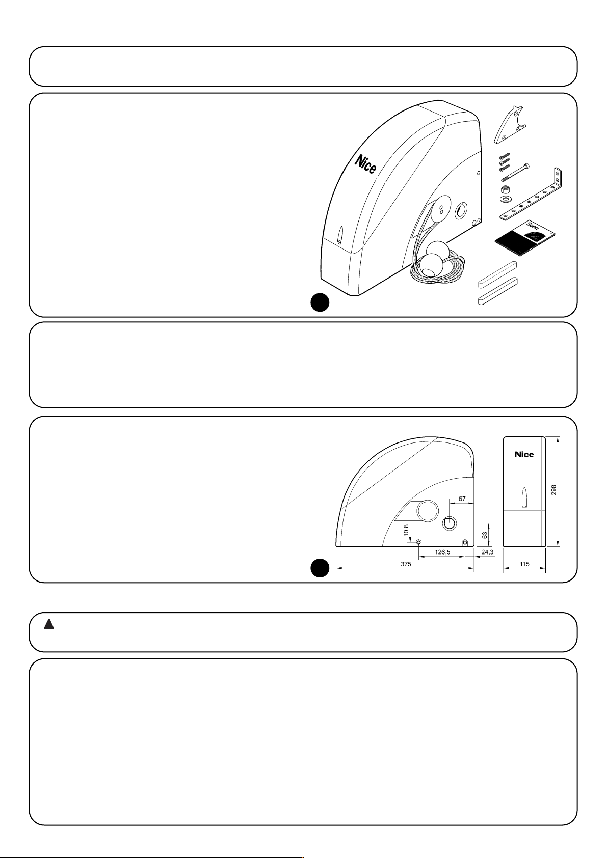
36
Avant de procéder à l'installation, vérifier l'intégrité des composants du produit, l'adéquation du modèle choisi et la compatibilité de l'environnement où l'automatisme sera installé.
3) Évaluer la faisabilité de l'installation
3.1) Vérifier les composants du produit (voir Fig. 1)
Vérifier l'intégrité de l'emballage;
déballer le produit et contrôler la présence de:
- 1 opérateur Soon
- 1 patte de fixation
- 4 demi-bagues de débrayage
- 2 clavettes
- 1 vis M8x130
- 1 écrou M8 indesserrable
- 1 rondelle D8
- 1 renvoi
- 3 vis autotaraudeuses noires
- 1 notice d'instructions
L'installation de l'automatisme doit être effectuée uniquement par du personnel qualifié, en respectant les présentes
instructions, les lois et les normes en vigueur.
!
4) Installer les différents composants
4.1) Schéma typique d'installation (voir Fig. 3)
La Fig. 3 illustre l'installation complète d'un opérateur Soon. Le dessin reporte les différents composants et les câbles nécessaires à leur
connexion, le tout assemblé et positionné suivant un schéma typique et courant.
Légende des composants mécaniques de la Fig. 3:
1 - Opérateur Soon
2 - Photocellule
3 - Sélecteur à clé
4 - Colonne pour photocellule
5 - Clignotant
6 - Émetteur
7 - Bord primaire
Légende des câbles électriques de la Fig. 3:
A - Ligne électrique d'alimentation
B - Clignotant avec antenne
C - Photocellules
D - Sélecteur à clé
E - Bord primaire
1
3.3) Vérifier les limites d'utilisation du produit (voir Fig. 2)
Vérifier les limites d'utilisation de l'opérateur Soon et des accessoires
que l'on prévoit d'installer, en évaluant si leurs caractéristiques sont
à même de satisfaire les exigences de l'environnement et les limitations indiquées cia-près:
• Vérifier que la taille de la porte sectionnelle est inférieure à 20 m
2
.
• Vérifier que l'arbre d'enroulement de la porte sectionnelle est com-
patible avec l'arbre de sortie du Soon à l'aide des clavettes fournies dans l'emballage.
• Vérifier que la patte de fixation au mur est suffisamment longue.
3.2) Vérifier que l'environnement est adapté
• Vérifier que l'environnement choisi pour l'installation est compa-
tible avec l'encombrement total de l'opérateur Soon (Fig. 2).
• Vérifier que l'environnement choisi ne présente pas d'obstacles
sur la trajectoire de la porte sectionnelle, qui peuvent limiter son
mouvement total en ouverture et en fermeture.
• Vérifier que l'environnement choisi pour l'installation permet une
exécution facile et sûre des manœuvres manuelles.
• Vérifier que tous les dispositifs à fixer sont positionnés sur une surface solide et à l'abri des chocs accidentels.
2
Page 37

37
F
4.2) Installer les composants mécaniques
Après avoir terminé les travaux de préparation de l'installation (par
exemple, les saignées pour les gaines des câbles électriques ou la
pose de conduits à l'extérieur; l'éventuelle fixation dans le béton des
tubes susdits et autres travaux nécessaires), on peut procéder au
montage et à l'installation complète de tous les composants mécaniques et électriques de Soon. Procéder en suivant l'ordre indiqué
ci-après.
Montage de l'opérateur Soon (voir Fig. 4)
1. (Fig. 4-a) Enfiler l'arbre de sortie de Soon dans l'arbre de transmission du mouvement de la porte sectionnelle en les accouplant à l'aide de la clavette fournie.
Effectuer cette opération avec la porte FERMÉE.
2. (Fig. 4-b) Fixer la patte de fixation sur Soon à l'aide de la vis, de
l'écrou et de la rondelle fournie.
3. (Fig. 4-c) Fixer la patte au mur avec une cheville (non fournie)
adaptée au matériau du mur.
4. (Fig. 4-d) On peut installer Soon en position horizontale avec un
renvoi particulier (fourni) qui doit être fixé avec trois vis (fournies)
dans la position illustrée, en faisant attention aux sorties des
câbles de débrayage.
4a 4b
4c 4d
3
Page 38

38
4.3) Pose des câbles électriques (voir Fig. 3 et Tab. 1)
Quand l'installation des différents composants mécaniques est terminée, procéder à la pose de tous les câbles électriques nécessaires en
se référant à la Fig. 3 qui montre la position typique de ces câbles, et au Tableau 1 qui en analyse en détail les caractéristiques techniques.
Les câbles utilisés pour les connexions des différents dispositifs doivent être adaptés au type d'installation que l'on comp-
te effectuer: si l'installation s'effectue dans un endroit couvert ou à l'intérieur, nous conseillons un câble type H03VV-F.
CARACTÉRISTIQUES DES CÂBLES ÉLECTRIQUES
(Les lettres associées aux câbles sont les mêmes que celles de la Fig. 3)
!
Notes: (*) Si le câble d'alimentation dépasse les 30 m, il faut utiliser un câble d'une plus grande section (exemple: 3 x 2,5 mm2et il faut pro-
céder à une mise à la terre à proximité de l'automatisme.
Connexion Type de câble Longueur maximum admise
A: Ligne électrique d'alimentation 1 câble (3 x 1,5 mm2) 30 m (*)
B: Clignotant 1 câble (2 x 1 mm2) 20 m
C: Antenne 1 câble blindé (type RG58) 20 m (longueur conseillée: moins de 5 m)
D: Photocellule 1 câble (2 x 0,5 mm2) 30 m
E: Sélecteur à clé 1 câble (4 x 0,5 mm2) 50 m
F: Connexion des bords mobiles 1 câble (2 x 0,5 mm2) 20 m
Tableau 1: liste des câbles
4.4) Procédure manuelle d'embrayage et de débrayage
Se référer à cette procédure à chaque fois que dans la
notice, on invite à « embrayer » ou à « débrayer » manuellement le mécanisme du SOON.
Notes:
Les manœuvres de débrayage ou d'embrayage du mécanisme doivent être faites exclusivement avec l'opérateur complètement arrêté.
• L'opération manuelle doit être effectuée dans les cas de manque
de courant, d'anomalie de l'installation ou si la notice le demande
expressément.
• Le débrayage manuel permet de manœuvrer librement la porte
sectionnelle
!
Pour le débrayage - tirer la boule A
Pour l'embrayage - tirer la boule B
Dans le but de garantir la sécurité de l'installateur et d'éviter des dommages aux composants de l'automatisme,
avant d'effectuer les connexions électriques ou d'embrocher le récepteur radio, vérifier que la logique de commande
est DÉCONNECTÉE du secteur électrique et des éven-tuelles batteries tampon.
!
5) Effectuer les connexions électriques
5.1) Connecter tous les dispositifs
Toutes les connexions électriques doivent être réalisées avec l'installation hors tension.
1. Pour éliminer le couvercle de protection et accéder à la logique
électronique de commande de Soon il faut enlever la vis et soulever le couvercle en le tirant vers le haut (Fig. 5).
2. Desserrer le presse-étoupe libre et faire passer les câbles pour la
connexion aux bornes de la logique. Laisser les câbles 20÷30
cm plus longs que nécessaire. Voir le tableau N°1 pour le type
de câble et la Fig. 6 pour les connexions.
3. Connecter les câbles suivant le schéma de la Fig. 7. Pour plus
de commodité, les bornes sont extractibles.
4. Quand les connexions sont terminées, bloquer les câbles en ser-
rant le presse-étoupe. La partie du câble d'antenne en excès
doit être fixée aux autres câbles à l'aide d'un autre collier.
65
Page 39

39
F
7
FLASH Cette sortie est programmable (voir la DEUXIÈME PARTIE du manuel) pour connecter l'un des dispositifs suivants:
Clignotant Si elle est programmée comme « clignotant » sur la sortie « FLASH » il est possible de connecter un cli-
gnotant NICE “LUCY B” avec une ampoule à 12 V 21 W type auto.
Durant la manœuvre elle clignote à une fréquence de 0,5 s allumée et 0,5 s éteinte.
Sortie « Voyant porte ouverte » Si elle est programmée comme « voyant porte ouverte » sur la sortie « FLASH » il
est possible de connecter un voyant 24 V max. 5 W pour la signalisation de la porte ouverte.
Elle peut également être programmée pour d'autres fonctions; voir la DEUXIÈME PARTIE de la notice.
Ventouse* Si elle est programmée comme « ventouse » sur la sortie « FLASH » il est possible de connecter une ventouse 24 V max. 10 W (versions avec électroaimant uniquement, sans dispositifs électroniques). Quand la porte est fermée la ventouse est activée en bloquant la porte. Durant la manœuvre d'ouverture ou de fermeture elle est désactivée.
Verrou électrique* Si elle est programmée comme « verrou électrique » sur la sortie « FLASH » il est possible de connecter un verrou électrique avec pêne-piston 24 V max. 10 W (versions avec électroaimant uniquement, sans dispositifs électroniques). Durant la manœuvre d'ouverture le verrou électrique est activé et reste actif pour libérer la porte et exécuter la
manœuvre. Lors de la manœuvre de fermeture, s'assurer que le verrou électrique se réenclenche mécaniquement.
Serrure électrique* Si elle est programmée comme « serrure électrique » sur la sortie « FLASH » il est possible de
connecter une serrure électrique avec pêne-piston 24 V max. 10 W (versions avec électroaimant uniquement, sans dispositifs électroniques). Durant la manœuvre d'ouverture la serrure électrique est activée et reste active pendant une courte période pour libérer la porte et exécuter la manœuvre. Lors de la manœuvre de fermeture, s'assurer que la serrure
électrique se réenclenche mécaniquement.
BLUEBUS Sur cette borne, on peut connecter les dispositifs compatibles; ils sont tous connectés en parallèle avec seulement deux
conducteurs sur lesquels transitent aussi bien l'alimentation électrique que les signaux de communication.
D'autres informations sur BlueBUS se trouvent dans le paragraphe « 5.2 - Connecter les dispositifs BlueBUS ».
STOP
Entrée pour dispositifs qui bloquent ou éventuellement arrêtent la manœuvre en cours; en adoptant certaines solutions sur l'entrée,
il est possible de connecter des contacts type « Normalement Fermé », « Normalement Ouvert », des dispositifs à résistance constante
ou de type optique. D'autres informations sur STOP se trouvent dans le paragraphe « 5.3 - Connecter les dispositifs à l'Entrée STOP ».
PP entrée pour dispositifs qui commandent le mouvement en mode Pas à Pas; on peut y connecter des contacts de type
« Normalement Ouvert ».
OPEN entrée pour dispositifs qui commandent le mouvement d'ouverture uniquement; on peut y connecter des contacts de
type « Normalement Ouvert ».
CLOSE entrée pour dispositifs qui commandent le mouvement de fermeture uniquement; on peut y connecter des contacts de
type « Normalement Ouvert ».
ANTENNA entrée pour la connexion de l'antenne pour récepteur radio (l'antenne est incorporée sur LUCY B).
* Seuls les dispositifs contenant uniquement l'électroaimant peuvent être raccordés
Ne pas utiliser de dispositifs différents de ceux qui sont prévus
!
Page 40

40
5.2) Connecter les dispositifs bluebus
BlueBUS est une technique qui permet d'effectuer les connexions
des dispositifs compatibles avec seulement deux conducteurs sur
lesquels transitent aussi bien l'alimentation électrique que les
signaux de communication. Tous les dispositifs sont connectés en
parallèle sur les 2 mêmes conducteurs de BlueBUS sans devoir respecter une polarité quelconque; chaque dispositif est reconnu individuellement car au cours de l'installation le système lui attribue une
adresse univoque. Il est possible de connecter à BlueBUS, par
exemple: des photocellules, des dispositifs de sécurité, des boutons
de com-mande, des voyants de signalisation, etc. La logique de
com-mande de SOON reconnaît un par un tous les dispositifs
connectés à travers une procédure de reconnaissance ad hoc et est
en mesure de détecter de manière extrêmement sûre toutes les
éventuelles anomalies. Pour cette raison, à chaque fois qu'on ajoute ou qu'on enlève un dispositif connecté à BlueBUS il faudra effectuer dans la logique la procédure de reconnaissance décrite dans le
paragraphe « 7.1 - Mémorisation dispositifs ».
5.2.2) Photodétecteur FT210B
Le photodétecteur FT210B réunit dans un seul dispositif un système
de limitation de la force (type C suivant la norme EN12453) et un
détecteur de présence qui détecte les obsta-cles présents sur l'axe
optique entre l'émetteur TX et le récepteur RX (type D suivant la norme EN12453). Dans le photodétecteur FT210B, les signaux de l'état
du bord sensible sont envoyés à travers le rayon de la photocellule
en intégrant les 2 systèmes dans un seul dispositif. La partie émettrice située sur le tablier est alimentée par des batteries, ce qui permet d'éliminer les systèmes de connexion, peu esthétiques; les circuits spéciaux réduisent la consommation de la batterie pour garantir jusqu'à 15 ans de durée (voir les détails sur la durée estimée dans
les instructions du produit).
Un seul dispositif FT210B associé à un bord sensible (TCB65 par
exemple) permet d'atteindre le niveau de sécurité du «bord primaire»
requis par la norme EN12453 pour n'importe quel «type d'utilisation»
et «type d'activation». Le photodétecteur FT210B associé à des bords
sensibles «à variation de résistance» (8,2KΩ), maintient la sécurité en
cas de défaut unique (catégorie 3 selon EN 954-1). Il dispose d'un circuit spécial anticollision qui évite les interférences avec d'autres détecteurs même s'ils ne sont pas synchronisés et permet d'ajouter
d'autres photocellules; par exemple, en cas de passage de véhicules
lourds où l'on place normalement une deuxième photocellule à 1 m du
sol. Pour tout renseignement supplémentaire sur les modalités de
connexion et d'adressage, voir la notice technique de FT210B.
5.3) Connecter les dispositifs à l'entrée stop
STOP est l'entrée qui provoque l'arrêt immédiat de la manœuvre suivi d'une brève inversion.
On peut connecter à cette entrée des dispositifs avec sortie à
contact normalement ouvert « NO », normalement fermé « NF » ou
des dispositifs avec sortie à résistance constante 8,2KΩ ou de type
optique, par exemple des bords sensibles.
Comme pour BlueBUS, la logique reconnaît le type de dispositif
connecté à l'entrée STOP durant la phase de reconnaissance (voir
paragraphe « 7.1 - Mémorisation dispositifs); ensuite on a un STOP
quand une variation quelconque se vérifie par rapport à l'état reconnu.
En adoptant certaines solutions, on peut connecter à l'entrée STOP
plusieurs dispositifs, même de type différent:
• Plusieurs dispositifs NO peuvent être connectés les uns aux autres
en parallèle sans aucune limite de nombre.
• Plusieurs dispositifs NF peuvent être connectés les uns aux autres
en série sans aucune limite de nombre;
5.2.1) Photocellules
Le système « BlueBUS » permet, à travers l'adressage avec les
cavaliers prévus à cet effet, la reconnaissance des photocellules de
la part de la logique et d'attribuer la fonction de détection correcte.
L'opération d'adressage doit être faite aussi bien sur TX que sur RX
(en plaçant les cavaliers de la même manière) en vérifiant qu'il n'y a
pas d'autres paires de photocellules ayant la même adresse.
Dans un automatisme pour portes sectionnelles avec SOON on peut
installer les photocellules suivant la représentation de la Fig. 8. Après
l'installation ou l'enlèvement de photocellules, il faudra effectuer
dans la logique la phase de reconnaissance comme le décrit le paragraphe « 7.1 - Mémorisation disposi-tifs ».
8
PHOTO
Photocellule h = 50
avec intervention en fermeture
PHOTO II
Photocellule h = 100
avec intervention en fermeture
PHOTO 1
Photocellule h = 50
avec intervention tant en fermeture qu'en ouverture
PHOTO 1 II
Photocellule h = 100
avec intervention tant en fermeture qu'en ouverture
PHOTO 2
Photocellule
avec intervention en ouverture
PHOTO 2 II
Photocellule
avec intervention en ouverture
PHOTO 3
CONFIGURATION NON AUTORISÉE
Tableau 2: adresses des photocellules
Photocellule Cavaliers Photocellule Cavaliers
Page 41

41
F
5.4) Connecter l'alimentation électrique
Pour l'alimentation électrique de SOON il suffit de brancher sa fiche électrique dans une prise de courant. Utiliser éventuellement un adaptateur du type disponible dans le commerce si la fiche de SOON ne correspond pas à la prise disponible.
• Deux dispositifs avec sortie à résistance constante 8,2KΩ peuvent
être connectés en parallèle; s'il y a plus de 2 dispositifs, tous doivent être connectés en « cascade » avec une seule résistance terminale de 8,2KΩ;
• Il est possible de combiner NO et NF en mettant les deux contacts
en parallèle, en prenant la précaution de mettre en série au contact
NF une résistance de 8,2KΩ (cela donne aussi la possibilité de
combiner 3 dispositifs: NO, NF et 8,2KΩ).
Si l'entrée STOP est utilisée pour connecter des dispositifs avec fonctions de sécurité, seuls les dispositifs avec
sortie à résistance constante 8,2KΩ ou les dispositifs
optiques OPTO SENSOR garantissent une per-formance
de sécurité de catégorie 3 selon la norme EN 954-1.
Pour la connexion d'un dispositif optique type OPTO SENSOR exécuter par contre les connexions comme dans la Fig. 9:
!
9
Les opérations successives seront effectuées sur des circuits électriques sous tension et les manœuvres pourront
résulter dangereuses! Opérer par conséquent avec attention et jamais seuls.
Quand l'installation des composants est terminée et que les connexions électriques ont été effectuées, il faut faire immédiatement quelques
vérifications sur le fonctionnement correct de l'installation, avant de continuer. Effectuer ensuite les opérations énumérées ci-après en les
cochant au fur et à mesure, après avoir vérifié la conformité des résultats.
!
6) Premier allumage de l'installation - vérifications
7) Mémorisation dispositifs et position
6.1) Test de fonctionnement
Dès que l'opérateur SOON est alimenté, il est conseillé de faire
quelques vérifications élémentaires:
K Vérifier que la led BLUEBUS clignote régulièrement à la fréquen-
ce d'un clignotement à la seconde;
K Si les photocellules sont présentes, vérifier que les led sur les
photocellules clignotent elles aussi (aussi bien sur TX que sur
RX); la fréquence de clignotement n'est pas significative, elle est
liée à d'autres facteurs.
K Vérifier que le dispositif connecté à la sortie FLASH est éteint.
K Vérifier que l'éclairage automatique est éteint.
Si tout cela ne se vérifie pas, il faut couper immédiatement l'alimentation de la logique de commande et contrôler plus attentivement les
connexions électriques.
7.1) Mémorisation dispositifs
Après le branchement au secteur il faut faire reconnaître par la
logique de commande les dispositifs connectés aux entrées BLUEBUS et STOP. Avant cette phase, les led L1 et L2 clignotent pour
indiquer qu'il faut effectuer la reconnaissance des dispositifs.
La phase de reconnaissance des dispositifs doit être
exécutée même s'il n'y a aucun dispositif connecté.
1. Presser et maintenir enfoncées les touches [▲] et [Set];
2. Relâcher les touches quand les led L1 et L2 commencent à cli-
gnoter très rapidement (au bout d'environ 3s);
3. Attendre quelques secondes que la logique termine la recon-
naissance des dispositifs;
À la fin de la reconnaissance, la led STOP doit rester allumée, les led
L1 et L2 s'éteindront (les led L3 et L4 commenceront éventuellement
à clignoter).
La phase de reconnaissance des dispositifs connectés peut être
refaite à tout moment y compris après l'installation, par exemple si
un nouveau dispositif est ajouté.
!
10
Page 42

42
7.2) Mémorisation des positions
Après la reconnaissance des dispositifs il faut faire reconnaître par la logique les positions d'ouverture et de fermeture de la porte. On peut
programmer jusqu'à 6 positions qui sont:
Position Signification
A1 Position d'ouverture maximum désirée. Quand la porte arrive dans cette position, elle s'arrête.
RA1 Position de début ralentissement durant la manœuvre d'ouverture. Quand la porte arrive dans cette position, le moteur
décélère en se portant à la vitesse minimum.
RINT Position de ralentissement intermédiaire dans la manœuvre de fermeture. En programmant ce point, la porte commence
à décélérer environ 50 cm avant, de manière à passer la position RINT à la vitesse minimum. Passée la position RINT le
moteur se reporte à la vitesse programmée.
AP Position d'ouverture partielle. C'est la position dans laquelle la porte s'arrête après avoir donné une commande
d'ouverture partielle.
RA0 Position de début ralentissement durant la manœuvre de fermeture. Quand la porte arrive dans cette position, le moteur
décélère en se portant à la vitesse minimum.
A0 Position de fermeture maximum. Quand la porte arrive dans cette position, elle s'arrête.
Quand les positions n'ont pas été mémorisées, les led L3 et L4 clignotent.
Nous décrivons ci-après la procédure pour la mémorisation des positions. Les positions A1 et A0 doivent être programmées tandis que les
autres peuvent être sautées. Dans ce dernier cas, elles seront calculées automatiquement par la logique de commande.
1. Presser la touche [Set] + [▼] pendant 3 secondes pour entrer en mémorisation positions.
La led L1 clignote: programmation position A1
2. Avec les touches [▲] ou [▼] déplacer la porte dans la position d'ouverture maximum.
3. Presser la touche [Set] pendant 2 secondes pour confirmer la position A1. La led L1 reste allumée.
La led L2 clignote: programmation position RA1
4. Si l'on ne souhaite pas programmer la position de ralentissement ouverture, presser rapidement 2 fois la touche [Set] pour passer
à la programmation successive, la led L2 reste éteinte. Autrement, continuer la séquence d'opérations.
5. Avec les touches [▲] ou [▼] déplacer la porte dans la position de ralentissement ouverture.
6. Presser la touche [Set] pendant 2 secondes pour confirmer la position RA1. La led L2 reste allumée.
La led L4 clignote: programmation position RINT
7. Si l'on ne souhaite pas programmer la position de ralentissement intermédiaire, presser rapidement 2 fois la touche [Set] pour
passer à la programmation successive, la led L4 reste éteinte. Autrement, continuer la séquence d'opérations.
8. Avec les touches [▲] ou [▼] déplacer la porte dans la position de ralentissement intermédiaire.
9. Presser la touche [Set] pendant 2 secondes pour confirmer la position RINT. La led L4 reste allumée.
La led L5 clignote: programmation position RAP
10. Si l'on ne souhaite pas programmer la position d'ouverture partielle, presser rapidement 2 fois la touche [Set] pour passer à la
programmation successive, la led L5 reste éteinte. Autrement, continuer la séquence d'opérations.
11. Avec les touches [▲] ou [▼] déplacer la porte dans la position d'ouverture partielle.
12. Presser la touche [Set] pendant 2 secondes pour confirmer la position RAP. La led L5 reste allumée.
La led L7 clignote: programmation position RA0
13. Si l'on ne souhaite pas programmer la position de ralentissement fermeture, presser rapidement 2 fois la touche [Set] pour passer
à la programmation successive, la led L7 reste éteinte. Autrement, continuer la séquence d'opérations.
14. Avec les touches [▲] ou [▼] déplacer la porte dans la position de ralentissement fermeture.
15. Presser la touche [Set] pendant 2 secondes pour confirmer la position RA0. La led L7 reste allumée.
La led L8 clignote: programmation position A0
16. Avec les touches [▲] ou [▼] déplacer la porte dans la position de fermeture maximum.
17. Presser la touche [Set] pendant 2 secondes pour confirmer la position A0. La led L8 reste allumée.
18. Quand on relâche la touche [Set] toutes les led s'éteignent.
19. Donner une commande d'ouverture en pressant la touche [Open] pour effectuer une manœuvre complète d'ouverture.
20. Donner une commande de fermeture en pressant la touche [Close] pour effectuer une manœuvre complète de fermeture.
Durant ces manœuvres la logique de commande mémorise la force
nécessaire dans les mouvements d'ouverture et de fermeture.
Il est important que ces premières manœuvres ne soient
pas interrompues, par ex. par une commande d'ARRÊT.
La phase de reconnaissance des positions peut être refaite à tout
moment même après l'installation; il suffit de recommencer à partir
du point 1. Si par contre il est nécessaire de modifier une seule position, répéter la séquence d'opérations à partir du point 1 et sauter la
programmation des positions à exclure en pressant rapidement 2
fois la touche [Set] pour chaque position à sauter.
11
Page 43

43
F
8) Effectuer l'essai final de l'installation
8.1) Test pour l'essai final
Chaque élément de l'automatisme comme par exemple les
bords sensibles, les photocellules, l'arrêt d'urgence, etc.
demande une phase spécifique d'essai; pour ces dispositifs, il faudra effectuer les procédures figurant dans les
notices techniques correspondantes.
Pour l'essai de SOON, effectuer les opérations suivantes:
1. Vérifier que tout ce qui est prévu dans le chapitre 1 « AVERTISSEMENTS » est respecté.
2. Débrayer la porte du moteur en tirant le cordon de débrayage
vers le bas. Vérifier qu'il est possible de bouger manuellement la
porte en ouverture et en fermeture avec une force ne dépassant
pas 225 N.
3. Embrayer la porte au moteur en tirant manuellement le cordon
d'embrayage.
4. En utilisant le sélecteur ou l'émetteur radio, effectuer des essais
de fermeture et d'ouverture de la porte et vérifier que le comportement correspond à ce qui est prévu.
5. Il convient d'effectuer différentes manœuvres pour contrôler le
bon coulissement de la porte et détecter les éventuels défauts
de montage et de réglage ainsi que la présence de points de
frottement.
6. Vérifier un par un le fonctionnement correct de tous les dispositifs de sécurité présents dans l'installation (photocellules, bords
sensibles, etc.). En particulier, à chaque fois qu'un dispositif
intervient, la led « BlueBUS » sur la logique de commande effectue 2 clignotements plus rapides qui confirment qu'elle reconnaît
l'événement.
7. Pour le contrôle des photocellules et en particulier pour contrôler qu'il n'y a pas d'interférences avec d'autres dispositifs, passer un cylindre d'un diamètre de 5 cm et d'une longueur de 30
cm sur l'axe optique, d'abord à proximité de TX, puis de RX, et
enfin au centre entre les deux et vérifier que dans tous les cas le
dispositif intervient en passant de l'état d'actif à l'état d'alarme
et vice versa; pour finir, vérifier que cela provoque dans la logique
l'action prévue, par exemple: dans la manœuvre de fermeture,
vérifier que cette action provoque l'inversion du mouvement.
8. Si la protection contre les situations dangereuses provoquées
par le mouvement de la porte a été assurée à travers la limitation
de la force d'impact, il faut effectuer la mesure de la force conformément à ce qui est prévu par la norme EN 12445. Si le réglage de la « Vitesse » ou le contrôle de la « Force Moteur » sont utilisés pour aider le système à réduire la force d'impact, essayer et
trouver le réglage qui donne les meilleurs résultats.
8.2) Mise en service
La mise en service ne peut être faite que si toutes les
phases d'essai de Soon et des autres dispositifs ont été
exécutées avec résultat positif. La mise en service partielle ou dans des situations « provisoires » n'est pas autorisée.
1. Réaliser et conserver pendant au moins 10 ans le dossier technique de l'automatisme qui devra comprendre au minimum: dessin d'ensemble de l'automatisation, schéma des connexions
électriques, analyse des risques et solutions adoptées, déclaration de conformité du fabricant de tous les dispositifs utilisés
(pour Soon, utiliser la déclaration CE de conformité ci-jointe),
exemplaire de la notice technique et du plan de maintenance de
l'automatisme;
2. Appliquer sur la porte une plaquette contenant au moins les
données suivantes: type d'automatisme, nom et adresse du
constructeur (responsable de la « mise en service »), numéro de
série, année de construction et marque CE;
3. Fixer de manière permanente à proximité de la porte une étiquette ou une plaque indiquant les opérations à effectuer pour le
débrayage et la manœuvre manuelle.
4. Fixer de manière permanente sur la porte une étiquette ou une
plaque avec cette image (hauteur minimum 60 mm).
5. Remplir et remettre au propriétaire la déclaration de conformité
de l'automatisme;
6. Rédiger et remettre au propriétaire de l'automatisme la notice «
Instructions et avertissements pour l'utilisation de l'automatisme »;
7. Réaliser et remettre au propriétaire le plan de maintenance de
l'automatisme (qui doit regrouper toutes les prescriptions pour la
maintenance de chaque dispositif).
8. Avant de mettre en service l'automatisme, informer le propriétaire, de manière adéquate et par écrit (par exemple dans le
manuel d'instructions et d'avertissements pour l'utilisation de
l'automatisme), sur les risques encore présents.
Page 44

44
Cette DEUXIÈME PARTIE décrit comment personnaliser le fonctionnement de l'automatisme, à travers les réglages et options à mémoriser
dans la mémoire de la Logique de commande. Une section finale est consacrée à la résolution des problèmes, à la maintenance et à la mise
au rebut du produit.
9) Instructions pour personnaliser le fonctionnement de l'automatisme
Des fonctions programmables sont disponibles dans la logique de
commande de SOON; le paramétrage des fonctions s'effectue à l'aide des trois touches présentes sur la logique: [▲] [Set] [▼] et sont
visualisées par 8 led: L1….L8.
Les fonctions programmables disponibles sur SOON sont réparties
en deux niveaux:
Premier niveau: fonctions réglables en mode ON-OFF (actif ou
non actif); dans ce cas, chaque led L1....L8 indique une fonction, si
elle est allumée la fonction est active, si elle est éteinte la fonction
n'est pas active; voir Tab. 3.
Deuxième niveau: paramètres réglables sur une échelle de
valeurs (valeurs d'1 à 8); dans ce cas, chaque led L1….L8 indique
la valeur réglée parmi les 6 possibles; voir Tab. 4.
10) Programmations
La touche « OPEN » permet de commander l'ouverture de la porte ou de
déplacer vers le haut le point de programmation
La touche « STOP » permet d'arrêter la manœuvre et si elle est pressée
plus de 5 secondes, elle permet d'entrer en programmation.
La touche “CLOSE” permet de commander la fermeture de la porte ou de
déplacer vers le bas le point de programmation.
9.1) Touches de programmation
Sur la logique de commande de SOON se trouvent 3 touches qui peuvent être utilisées
aussi bien pour la commande de la logique durant les essais que pour les programmations:
12
OPEN
▲
STOP
SET
CLOSE
▼
Led Fonction Description
L1 Fermeture automatique Cette fonction permet une fermeture automatique de la porte après le temps de pause programmé; le
temps de pause est réglé en usine à 30 secondes mais peut être modifié et réglé sur 10, 20, 40, 60, 80,
120, 160 et 200 secondes. Si la fonction n'est pas active, le fonctionnement est « semi-automatique ».
L2 Refermeture après Cette fonction permet de garder la porte ouverte uniquement le temps nécessaire au transit, en effet l'intervention
passage devant la de « Photo » provoque toujours une refermeture automatique avec un temps de pause de 5 s (indépendamment
photocellule de la valeur programmée); le comportement varie suivant si la « Fermeture Automatique » est active ou pas.
Avec « Fermeture Automatique » inactive: La porte atteint toujours la position d'ouverture totale (même si
Photo est libérée avant). La libération de la photocellule provoque la refermeture automatique au bout de 5 s.
Avec « Fermeture Automatique » active: la manœuvre d'ouverture s'arrête juste après que les photocellules
aient été libérées et provoque la manœuvre de refermeture automatique au bout de 5 s.
La fonction de « refermeture après passage devant la photocellule » est toujours désactivée dans les
manœuvres interrompues avec une commande de Stop.
Si la fonction « refermeture après passage devant la photocellule » n'est pas active, le temps de pause sera
celui qui est programmé ou bien il n'y aura pas de refermeture automatique si la fonction n'est pas active.
L3 Ferme toujours La fonction « Ferme toujours » intervient, en provoquant une fermeture, quand au retour de l'alimentation la
logique détecte la porte ouverte. Pour des questions de sécurité, la manœuvre est précédée par 3 s de
préclignotement. Si la fonction n'est pas active au retour de l'alimentation, la porte restera arrêtée.
L4 Stand-By Cette fonction permet de réduire au maximum la consommation d'énergie. Si cette fonction est active, 1
minute après la fin de la manœuvre, la logique éteint BlueBUS (et donc les dispositifs) et toutes les led sauf
la led BlueBUS qui clignotera plus lentement. Quand une commande arrive, la logique rétablit le plein
fonctionnement. Si la fonction n'est pas active, il n'y aura pas de réduction de la consommation.
L5 Inversion longue Cette fonction permet de sélectionner le type d'inversion effectuée par la porte à cause de l'intervention de
STOP et du limiteur de force. Si la fonction n'est pas active l'inversion est brève (15 cm environ). Si la
fonction est active l'inversion s'effectue jusqu'à la position d'ouverture ou de fermeture maximum.
L6 Préclignotement Avec la fonction de préclignotement, une pause de 3 s est ajoutée entre l'allumage du clignotant et le début
de la manœuvre pour avertir l'utilisateur de la situation de danger. Si la fonction n'est pas active, l'allumage
du clignotant coïncide avec le début de la manœuvre.
L7 Sensibilité Cette fonction permet d'augmenter considérablement la sensibilité du moteur dans la détection des
obstacles. Si elle est utilisée comme aide pour la mesure de la force d'impact régler aussi les paramètres
« Vitesse » et « Force moteur » dans le menu du deuxième niveau.
L8 Compensation Cette fonction permet de récupérer l'allongement dans le temps des câbles métalliques de la porte et elle
est subordonnée à l'emploi d'un bord sensible à variation de résistance 8,2KΩ ou de type optique OSE.
Durant le fonctionnement normal de SOON, quand aucune manœuvre n'est en cours, les led L1…L8 sont allumées ou éteintes suivant l'état
de la fonction à laquelle elles correspondent, par exemple L1 est allumée si la « fermeture automatique » est active.
Tableau 3: liste fonctions programmables: premier niveau
10.1) Fonctions premier niveau
Page 45

45
F
Temps de
pause
Fonction P.P.
Vitesse
moteur
Sortie
FLASH
Force moteur
en ouverture
Force moteur
en fermeture
L1
L2
L3
L4
L5
L6
L7
L8
L1
L2
L3
L4
L5
L6
L7
L8
L1
L2
L3
L4
L5
L6
L7
L8
L1
L2
L3
L4
L5
L6
L7
L8
L1
L2
L3
L4
L5
L6
L7
L8
L1
L2
L3
L4
L5
L6
L7
L8
10 secondes
20 secondes
40 secondes
60 secondes
80 secondes
120 secondes
160 secondes
200 secondes
Ouverture - stop - fermeture - stop
Ouverture - stop - fermeture - ouverture
Ouverture - fermeture - ouverture - fermeture
Fonctionnement collectif
Fonctionnement collectif 2 (plus de 2 s entraîne un arrêt)
Pas à pas 2 (moins de 2 s entraîne une ouverture partielle)
Commande « par action maintenue »
Ouverture en « semi-automatique », fermeture avec commande « par action maintenue »
Vitesse 1 (30 % - lente)
Vitesse 2 (44 %)
Vitesse 3 (58 %)
Vitesse 4 (72 %)
Vitesse 5 (86 %)
Vitesse 6 (100 % - rapide)
Ouverture V4, fermeture V2
Ouverture V6, fermeture V4
Voyant porte ouverte
Active si la porte est fermée
Active si la porte est ouverte
Clignotant
Verrou électrique
Serrure électrique
Ventouse
Voyant maintenance
Force 1 (basse)
Force 2
Force 3
Force 4
Force 5
Force 6
Force 7
Force 8 (haute)
Force 1 (basse)
Force 2
Force 3
Force 4
Force 5
Force 6
Force 7
Force 8 (haute)
10.3) Fonctions deuxième niveau (paramètres réglables )
Tableau 4: liste fonctions programmables: deuxième niveau
Led d'entrée Paramètre Led (niveau) Valeur Description
Règle le temps de pause,
c'est-à-dire le temps avant
la refermeture automatique.
La fonction n'a d'effet que
si la fermeture automatique
est active.
Règle la séquence de
commandes associées à
l'entrée P.P. ou bien à la 1
re
commande radio.
Règle la vitesse du moteur
durant la course normale.
Sélectionne le dispositif
connecté à la sortie FLASH.
Règle le système de
contrôle de la force du
moteur pour l'adapter au
poids de la porte durant la
manœuvre d'ouverture.
Règle le système de
contrôle de la force du
moteur pour l'adapter au
poids de la porte durant la
manœuvre de fermeture.
Note: “ ” représente le réglage fait en usine. SEGUE
L1
L2
L3
L4
L5
L6
10.2) Fonctions premier niveau
En usine, les fonctions du premier niveau sont toutes mises sur « OFF » mais on peut les modifier à tout moment en suivant les indications
données ci-après. Faire attention dans l'exécution de la procédure car il y a un temps maximum de 10 s entre la pression d'une touche et
l'autre, autrement la procédure se termine automatiquement en mémorisant les modifications faites jusqu'à ce moment-là.
Attendre 10 s pour sortir de la programmation pour temps maximum écoulé.
Note: les points 3 et 4 peuvent être répétés au cours de la même phase de programmation pour mettre d'autres fonctions en mode ON ou OFF.
1. Presser et maintenir enfoncée la touche [Set] pendant environ 3 s.
2. Relâcher la touche [Set] quand la led L1 commence à clignoter.
3. Presser les touches [▲] ou [▼] pour déplacer la led clignotante sur la led qui correspond à la fonction à modifier.
4. Presser la touche [Set] pour changer l'état de la fonction (clignotement bref = OFF; clignotement long = ON)
Page 46

46
SOON permet d'aviser l'utilisateur quand il faut procéder
à la maintenance de l'automatisme. Le nombre de
manœuvres après lequel s'effectue la signalisation est
sélectionnable parmi 8 niveaux, avec le paramètre
réglable « Avis de maintenance » (voir Tab. 4).
Le niveau 1 de réglage est « automatique » et tient compte de l'intensité
et des conditions des manœuvres, c'est-à-dire de l'effort et de la durée
de la manœuvre, tandis que les autres réglages sont fixés en fonction du
nombre de manœuvres. La signalisation de demande de maintenance
s'effectue à travers le clignotant ou le voyant de maintenance suivant la
programmation (voir Tab. 4).
Suivant le nombre de manœuvres effectuées par rapport à la limite programmée, le clignotant Flash et le voyant de maintenance donnent les
signalisations indiquées dans le Tab. 5
11) Avis de maintenance
Avis de
maintenance
Liste des
anomalies
L1
L2
L3
L4
L5
L6
L7
L8
L1
L2
L3
L4
L5
L6
L7
L8
Automatique (suivant la charge de travail des manœuvres)
1.000
2.000
4.000
6.000
8.000
10.000
12.000
Résultat 1remanœuvre (la plus récente)
Résultat 2emanœuvre
Résultat 3emanœuvre
Résultat 4emanœuvre
Résultat 5emanœuvre
Résultat 6emanœuvre
Résultat 7emanœuvre
Résultat 8
e
manœuvre
Led d'entrée Paramètre Led (niveau) Valeur Description
Règle le nombre de
manœuvres au bout duquel
il faut signaler la demande
de maintenance de
l'automatisme (voir
paragraphe 13 « Avis de
maintenance »).
Permet de vérifier le type
d'anomalie qui s'est vérifiée
dans les 8 dernières
manœuvres (voir
paragraphe « 14 Liste
historique des anomalies »).
Note: “ ” représente le réglage fait en usine.
Tous les paramètres peuvent être réglés suivant les préférences sans aucune contre-indication; seul les réglages « Force moteur en ouverture » « Force moteur en fermeture » pourraient demander une attention particulière:
• Il est déconseillé d'utiliser des valeurs de force élevées pour compenser le fait que le tablier a des points de friction anormaux. Une force
excessive peut compromettre le fonctionnement du système de sécurité ou endommager le tablier.
• Si le contrôle de la « Force moteur » est utilisé comme soutien du système pour la réduction de la force d'impact, après chaque réglage,
répéter la mesure de la force, comme le prévoit la norme EN 12445.
• L'usure et les conditions atmosphériques peuvent influencer le mouvement de la porte, périodiquement il faut recontrôler le réglage de la
force.
L7
L8
10.4) Programmations deuxième niveau
En usine, les paramètres réglables sont réglés comme l'illustre le Tab. 4 avec: “ ” mais ils peuvent être modifiés à tout moment suivant les
indications données ci-après. Faire attention dans l'exécution de la procédure car il y a un temps maximum de 10 s entre la pression d'une
touche et l'autre, autrement la procédure se termine automatiquement en mémorisant les modifications faites jusqu'à ce moment-là.
Attendre 10 s pour sortir de la programmation pour temps maximum écoulé.
Note: les points 3 à 7 peuvent être répétés au cours de la même phase de programmation pour régler plusieurs paramètres.
1. Presser et maintenir enfoncée la touche [Set] pendant environ 3 s.
2. Relâcher la touche [Set] quand la led L1 commence à clignoter.
3. Presser les touches [▲] ou [▼] pour déplacer la led clignotante sur la « led d'entrée » qui correspond au paramètre à modifier.
4. Presser et maintenir enfoncée la touche [Set], la pression doit être maintenue sur la touche [Set] pendant toute la durée des phases 5 et 6.
5. Attendre environ 3 s puis la led qui correspond au niveau actuel du paramètre à modifier s'allumera.
6. Presser les touches [▲] ou [▼] pour déplacer la led qui correspond à la valeur du paramètre.
7. Relâcher la touche [Set]
Nombre de manœuvres Signalisation sur Flash Signalisation sur voyant maintenance
Inférieur à 80 % de la limite Normal (0,5 s allumé, 0,5 s éteint) Allumé pendant 2 s au début de l'ouverture.
Entre 81 et 100 % de la limite Au début de la manœuvre, il reste allumé pendant 2 s puis Clignote pendant toute la manœuvre.
continue normalement.
Au-delà de 100 % de la limite Au début et à la fin de la manœuvre, il reste allumé pendant Clignote constamment.
2 s puis continue normalement.
Tableau 5: avis de maintenance avec Flash et voyant de maintenance
Page 47

47
F
11.1) Vérification du nombre de manœuvres effectuées
Avec la fonction d'« Avis de maintenance », il est possible de vérifier le nombre de manœuvres effectuées en pourcentage sur la limite fixée.
Pour le contrôle, procéder suivant les indications ci-après.
1. Presser et maintenir enfoncée la touche [Set] pendant environ 3 s.
2. Relâcher la touche [Set] quand la led L1 commence à clignoter.
3. Presser les touches [▲] o [▼] pour déplacer la led clignotante sur L7, c'est-à-dire la « led d'entrée » qui correspond au paramètre
« Avis de maintenance ».
4. Presser et maintenir enfoncée la touche [Set], la pression doit être maintenue sur la touche [Set] pendant toute la durée des
phases 5, 6 et 7.
5. Attendre environ 3 s puis la led qui représente le niveau actuel du paramètre « Avis de maintenance » s'allumera.
6. Presser puis relâcher immédiatement les touches [▲] et [▼].
7. La led correspondant au niveau sélectionné émettra quelques clignotements. Le nombre de clignotements identifie le pourcentage
de manœuvres effectuées (en multiples de 10 %) par rapport à la limite programmée. Par exemple: avec l'avis de maintenance
programmé sur L7, c'est-à-dire 10 000, 10 % correspond à 1 000 manœuvres; si la led de signalisation émet 4 clignotements, cela
signifie que l'on a atteint 40 % des manœuvres (c'est-à-dire entre 4 000 et 4 999 manœuvres). Si l'on n'a pas atteint 10 % des
manœuvres, il n'y aura aucun clignotement.
8. Relâcher la touche [Set].
SOON permet d'afficher les éventuelles anomalies qui se sont vérifiées lors des 8 dernières manœuvres, par exemple, l'interruption d'une manœuvre
due à l'intervention d'une photocellule ou d'un bord sensible. Pour vérifier la liste des anomalies procéder suivant les indications ci-après.
1. Presser et maintenir enfoncée la touche [Set] pendant environ 3 s.
2. Relâcher la touche [Set] quand la led L1 commence à clignoter.
3. Presser les touches [▲] ou [▼] pour déplacer la led clignotante sur L8, c'est-à-dire la « led d'entrée » pour le paramètre
« Liste des anomalies ».
4. Presser et maintenir enfoncée la touche [Set], la pression doit être maintenue sur la touche [Set] pendant toute la durée des
phases 5 et 6.
5. Attendre environ 3 s puis les led correspondant aux manœuvres qui ont eu des anomalies s'allumeront. La led L1 indique le résultat
de la manœuvre la plus récente, la led L8 indique le résultat de la huitième. Si la led est allumée, cela signifie que des anomalies se
sont vérifiées durant la manœuvre; si la led est éteinte, cela signifie que la manœuvre s'est terminée sans anomalies.
6. Presser les touches [▲] et [▼] pour sélectionner la manœuvre désirée: la led correspondante émettra un nombre de clignotements
égal à ceux qui sont exécutés normalement par le clignotant après une anomalie.
7. Relâcher la touche [Set].
11.2) Mise à zéro du compteur des manœuvres
Après avoir effectué la maintenance de l'installation, il faut mettre à zéro le compteur des manœuvres. Procéder suivant les indications du tableau 18.
1. Presser et maintenir enfoncée la touche [Set] pendant environ 3 s.
2. Relâcher la touche [Set] quand la led L1 commence à clignoter.
3. Presser les touches [▲] ou [▼] pour déplacer la led clignotante sur L7, c'est-à-dire la « led d'entrée » qui correspond au paramètre
« Avis de maintenance ».
4. Presser et maintenir enfoncée la touche [Set], la pression doit être maintenue sur la touche [Set] pendant toute la durée des
phases 5 et 6.
5. Attendre environ 3 s puis la led qui représente le niveau actuel du paramètre « Avis de maintenance » s'allumera.
6. Presser et maintenir enfoncées les touches [▲] et [▼] pendant au moins 5 s puis relâcher les 2 touches. La led correspondant au
niveau sélectionné effectuera une série de clignotements rapides pour signaler que le compteur des manœuvres a été mis à zéro.
7. Relâcher la touche [Set].
S'il est nécessaire d'alimenter des dispositifs extérieurs, par exemple
un lecteur de proximité pour cartes transpondeur ou bien l'éclairage
du sélecteur à clé, il est possible de prélever l'alimentation comme
l'indique la figure 12. La tension d'alimentation est de 24 Vcc -30 %
÷ +50 % avec courant maximum disponible de 100 mA.
13) Connexion d'autres dispositifs
12) Liste historique des anomalies
12
Page 48

48
14) Approfondissements: fonctions particulières
14.1) Fonction « Ouvre toujours »
La fonction « Ouvre toujours » est une propriété de la logique de commande qui permet de commander toujours une manœuvre d'ouverture quand la commande de « Pas à Pas » a une durée supérieure à 2 secondes; c'est utile par exemple pour connecter à la borne P.P. le
contact d'une horloge de programmation pour maintenir la porte sectionelle ouverte pendant une certaine plage horaire. Cette propriété est
valable quelle que soit la programmation de l'entrée P.P. à l'exclusion de la programmation comme « fonctionnement collectif 2 »; voir paramètre « Fonction P.P. » dans le Tab. 4.
15) Fonctionnement de l'automatisme avec émetteur et récepteur-radio « SM »
Sur la logique se trouve un connecteur pour l'installation d'un récepteur-radio embrochable type « SM » (Fig. 13), pour commander l'automatisme avec un émetteur-radio (le récepteur et l'émetteur sont
des accessoires en option). Les quatre Sorties du Récepteur permettent de donner à la logique les commandes suivantes.
Si on n'utilise pas l'antenne incorporée à LUCYB ou un autre type
d'antenne extérieure, visser le câble rigide fourni avec le récepteur à
la borne de l'antenne (Fig. 14).
14.2) Fonction « Manœuvre dans tous les cas »
Si un dispositif de sécurité quelconque fonctionne mal ou tombe en panne, il est possible dans tous les cas de commander et de manœuvrer la porte en mode « commande par action maintenue ». Pour tout détail, voir le paragraphe « Commande avec sécurités hors d'usage »
présent dans les « Instructions et recommandations destinées à l'utilisateur de l'opérateur SOON ».
Sortie n° 1 Commande « P.P. » (Pas à Pas)
Sortie n° 2 Commande « Ouverture partielle »
Sortie n° 3 Commande « Ouverture »
Sortie n° 4 Commande « Fermeture »
Tableau 6: commandes avec récepteur SMXI, SMXIS
16) Contrôle et diagnostic automatique des anomalies de fonctionnement
Durant le fonctionnement régulier, la logique de commande tient constamment les processus de l'automatisme sous contrôle et est en mesure de signaler les éventuelles anomalies à travers des séquences préétablies de clignotements émis par le clignotant, l'éclairage automatique
et la « led BlueBUS » (les clignotements diagnostics se réfèrent toujours à la dernière action accomplie par Soon). Pour comprendre la correspondance entre le nombre de clignotements et les causes, se référer au tableau suivant:
Tableau 7: clignotements de diagnostic
13 14
n° clig. Cause
1 Erreur synchronisation BlueBUS
2 Intervention de Photo ou erreur du Phototest
3 Force de l'opérateur insuffisante ou obstacle détecté durant la course
4 Intervention des dispositifs d'arrêt
5 Erreur sur les paramètres de la mémoire
6 Intervention limiteur de manœuvres interne
7 Manque de courant dans les circuits moteur
8 Surintensité dans les circuits moteur
Page 49
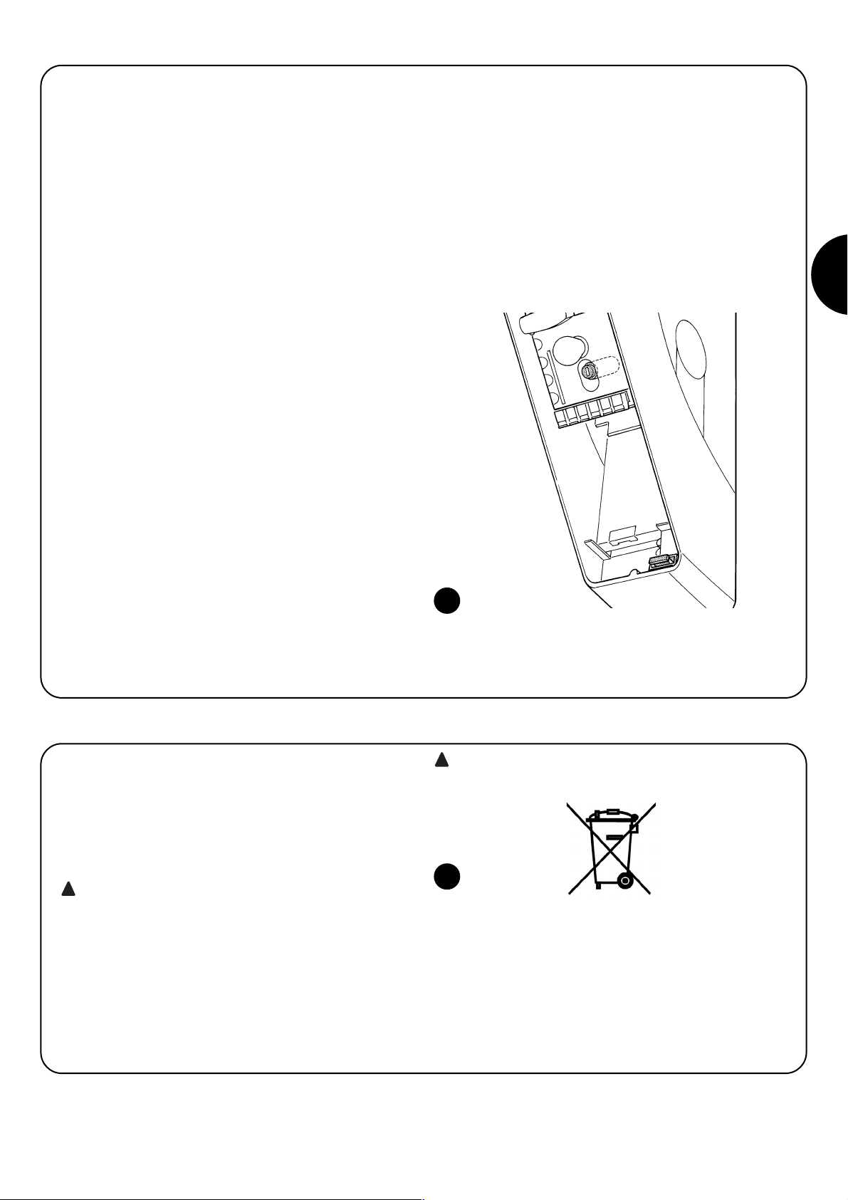
49
F
17) Que faire si… (Guide à la résolution des problèmes)
Nous fournissons ici un petit guide pour résoudre les problèmes qui
peuvent se présenter durant l'installation et la programmation de
l'automatisme.
•
…aucune manœuvre n'est commandée et la led “BLUEBUS” ne clignote pas
- Vérifier que Soon est alimenté à la tension de secteur à 230 V. Vérifier si les fusibles F1 et F2 (Fig. 15) sont grillés; si c'est le cas, identifier la cause de l'avarie et remplacer les fusibles par d'autres
ayant les mêmes valeurs de courant et caractéristiques.
•
…aucune manœuvre n'est commandée et le clignotant
est éteint.
- Vérifier que la commande est effectivement reçue. Si la commande arrive à l'entrée PP la led « PP » correspondante doit s'allumer;
si par contre on utilise l'émetteur radio, la led « Bluebus » doit faire deux clignotements rapides.
• …aucune manœuvre n'est commandée et le clignotant
fait quelques clignotements
Compter le nombre de clignotements et vérifier suivant les indications du Tab. 7.
• ...il y a une brève inversion durant la manœuvre
- La force sélectionnée pourrait être trop basse pour manœuvrer la
porte. Vérifier s'il y a des obstacles et sélectionner éventuellement
une force supérieure.
- Vérifier si un dispositif de sécurité connecté à l'entrée Stop est
intervenu.
• …la manœuvre est effectuée mais le dispositif connecté
à la sortie FLASH ne fonctionne pas
- Vérifier que le dispositif connecté à la sortie FLASH correspond
effectivement à celui programmé.
- Vérifier que quand le dispositif devrait être alimenté la tension arrive sur la borne du dispositif; si la tension arrive, le problème est dû
au dispositif qui devra être remplacé par un ayant les mêmes
caractéristiques. S'il n'y a pas de tension cela signifie qu'il y a une
surcharge électrique sur la sortie. Vérifier qu'il n'y a pas de courtcircuit sur le câble.
•
…durant la phase de mémorisation des positions, la led
L1 ou la led L8 clignotent rapidement
- Cela veut dire que la position de surcourse supérieure (clignotement rapide de L1) ou inférieure (clignotement rapide de L8) a été
atteinte.
- Si la led L1 clignote, effectuer une manœuvre de fermeture jusqu'à
ce que L1 arrête de clignoter rapidement. Démonter ensuite Soon
de l'arbre porte-ressorts, ouvrir la porte dans la position maximum
et réinstaller Soon depuis cette position.
- Si la led L8 clignote, effectuer une manœuvre d'ouverture jusqu'à
ce que L8 arrête de clignoter rapidement. Démonter ensuite Soon
de l'arbre porte-ressorts, fermer la porte dans la position maximum et réinstaller Soon depuis cette position.
15
Comme pour l'installation, à la fin de la durée de vie de ce produit,
les opérations de démantèlement doivent être effectuées par du personnel technique qualifié.
Ce produit est constitué de différents types de matériaux: certains peuvent être recyclés, d'autres doivent être mis au rebut. Informez-vous sur
les systèmes de recyclage ou de mise au rebut prévus par les normes
en vigueur dans votre région pour cette catégorie de produit.
Certains composants du produit peuvent contenir des
substances polluantes ou dangereuses qui pourraient avoir
des effets nuisibles sur l'environnement et sur la santé des
personnes s'ils n'étaient pas adéquatement éliminés.
Comme l'indique le symbole de la Fig. 16, il est interdit de jeter ce
produit avec les ordures ménagères. Procéder à la « collecte différenciée » des composants pour leur traitement conformément aux
méthodes prescrites par les normes locales en vigueur ou restituer
le produit au vendeur lors de l'achat d'un nouveau produit équivalent.
Les règlements locaux peuvent appliquer de lourdes
sanctions en cas d'élimination prohibée de ce produit.
!
!
16
18) Mise au rebut
Page 50

50
Soon
Inhaltsverzeichnis S.
Anweisungen für die Installation und
Inbetriebnahme der Automatisierung 51
1 Sicher arbeiten 51
1.1 Vorsichtsmassnahmen und Sicherheitshinweise 51
2 Die merkmale des produkts kennen 51
2.1 Produktbeschreibung, Einsatz und technische
Merkmale 51
3 Die durchführbarkeit der installation bewerten 52
3.1 Die Bestandteile des Produktes überprüfen 52
3.2 Die Eignung der Umgebung überprüfen 52
3.3 Die Einsatzgrenzen des Produktes überprüfen 52
4 Die verschiedenen bestandteile installieren 52
4.1 Typisches Installationsschema 52
4.2 Die mechanischen Bestandteile installieren 53
4.3 Die elektrischen Kabel verlegen 54
4.4 Ver- und Entriegelung von Hand 54
5 Die elektrischen anschlüsse ausführen 54
5.1 Alle Vorrichtungen anschließen 54
5.2 Die BlueBUS-Vorrichtungen anschließen 56
5.2.1 Photozellen 56
5.2.2 Lichtsensor FT210B 56
5.3 Vorrichtungen am Eingang STOP anschließen 56
5.4 Die Stromversorgung anschließen 57
6 Erstes einschalten der anlage - überprüfungen 57
6.1 Betriebstest 57
7 Vorrichtungen und positionen speichern 57
7.1 Vorrichtungen speichern 57
7.2 Positionen speichern 58
8 Die endabnahme der anlage ausführen 59
8.1 Test für die Endabnahme 59
8.2 Inbetriebsetzung 59
EINLEITUNG
Das vorliegende Handbuch erklärt, wie man den Sektionaltorantrieb Soon installiert, programmiert und bedient. Die verschiedenen Themen sind in drei Teile getrennt:
ERSTER TEIL: eine Schrittanleitung, die die notwendige
Schritte zur “physischen” Installation des Produktes und für
seine Inbetriebnahme schildert.
ZWEITER TEIL: er beschreibt, wie Soon durch die Programmierung einiger Sonderfunktionen und die Wahl von Optionen
und besonderer Einstellungen personalisiert werden kann.
Ein Abschnitt des Handbuchs ist auch der Wartung und Entsorgung des Produktes gewidmet.
Der erste und der zweite Teil des Handbuchs sind ausschließlich
für das Technische Fachpersonal bestimmt, das die Automatisierung
installieren wird. Keine dieser Informationen ist als für den Endbenutzer
des Produktes nützlich oder interessant zu betrachten.
!
9 Anweisungen für die Personalisierung der
Automatisierung 60
9.1 Programmierungstasten 60
10 Programmierungen 60
10.1 Funktionen des ersten niveaus 60
10.2 Programmierungen des ersten niveaus 61
10.3 Funktionen des zweiten niveaus
(einstellbaren Parameter) 61
10.4 Programmierungen zweiten niveaus 62
11 Wartungsanzeige 62
11.1 Überprüfung der anzahl an ausgeführten
bewegungen 63
11.2 Nullstellung des bewegungszählers 63
12 Liste der alarmhistorik 63
13 Verbindung sonstiger vorrichtungen 63
14 Weitere Auskünfte: Sonderfunktionen 64
14.1 Funktion “Öffnet Immer” 64
14.2 Funktion “Todmann” 64
15 Funktionsweise der automatisierung über
sender und funkempfänger “SM” 64
16 Kontrolle und automatische diagnose von
betriebsstörungen 64
17 Was tun, wenn...
(Leitfaden zum Lösen von Problemen) 65
18 Entsorgung 65
Page 51
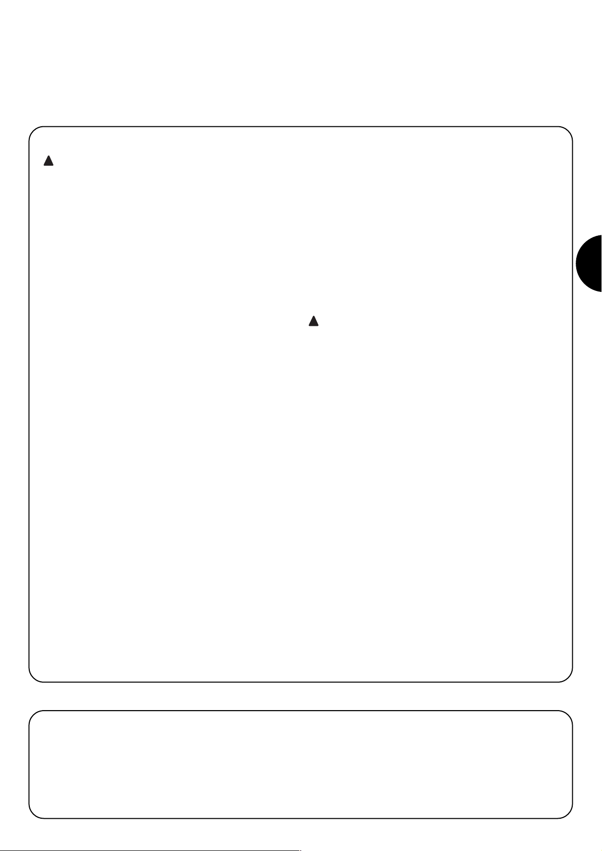
51
D
Anweisungen für die Installation und Inbetriebnahme
Im ERSTEN TEIL sind alle Installationsphasen des Produktes (mechanische Montage, elektrische Anschlüsse, Abnahme) und seine erste Inbetriebnahme (Einstellungen) Schritt für Schritt beschrieben.
Diesen Phasen gehen sehr wichtige Hinweise voraus, die Sicherheit, die
Merkmale des Produktes und die Durchführbarkeit der Anlage betreffen.
1.1) Vorsichtsmaßnahmen und sicherheitshinweise
Installation, Programmierung und Inbetriebnahme des Produktes
müssen von technisch qualifiziertem Personal unter genauester
Beachtung sowohl der diesbezüglich gültigen Gesetze und Vorschriften als auch der Anweisungen im vorliegenden Handbuch ausgeführt werden.
Das vorliegende Handbuch ist so aufgebaut, dass es bei der Installation, Programmierung und Inbetriebnahme des Antriebs Soon
Schritt für Schritt anleitet. Alle auszuführenden Arbeiten sind zusammen mit den notwendigen Anweisungen in der genauen Reihenfolge
angegeben, in der die Arbeitsphasen auszuführen sind.
Daher ist es wichtig, alle Abschnitte des Handbuchs vor Installationsbeginn zu lesen. Insbesondere sind die Abschnitte sehr aufmerksam zu lesen, die wichtige SICHERHEITSHINWEISE enthalten,
wie der vorliegende Abschnitt 1, der Abschnitt 3 - ÜBERPÜFUNGEN
VOR DER INSTALLATION UND EINSATZGRENZEN DES PRODUKTES sowie der Abschnitt 8 - ABNAHME UND INBETRIEBSETZUNG
DES SYSTEMS. Unter Berücksichtigung der Gefahren, die bei der
Installation und dem täglichen Gebrauch des Produktes auftreten
können, muss die Installation unter voller Einhaltung der Europarichtlinie Nr. 98/37/CE (Maschinenrichtlinie für die Realisierung eines
automatischen Tors) und insbesondere der Normen EN 12445, EN
12453 und EN 12635 erfolgen. Die Beachtung dieser Richtlinie wird
es Ihnen ermöglichen, mit größter Sicherheit vorzugehen und am
Ende der Arbeit die Erklärung der vermutlichen Konformität auszustellen und daher die Sicherheit der Anlage zu bestätigen.
ANMERKUNG: Weitere Auskünfte und Richtlinien zur Analyse der
Risiken, nützlich für die Realisierung von Ihnen ausgestellten der
Technischen Unterlagen stehen im Web unter www.niceforyou.com
zur Verfügung.
• Der Gebrauch von Soon zu einem anderen Einsatz als im vorlie-
genden Handbuch vorgesehen ist untersagt. Ein unsachgemäßer
Gebrauch kann Produktschäden und Personen und Gegenstände
gefährden.
• Es ist verboten, Änderungen an Bestandteilen des Produktes aus-
zuführen, falls nicht ausdrücklich im vorliegenden Handbuch angegeben. Nicht genehmigte Vorgänge können nur Betriebsstörungen
verursachen; Nice
®
lehnt jegliche Haftung für Schäden aufgrund
willkürlich geänderter Produkte ab.
• Vor der Installation ist die Risikoanalyse auszuführen, welche die
Liste der wesentlichen Sicherheitsanforderungen, vorgesehen in
Anlage I der Maschinenrichtlinie einschließen und die jeweiligen,
angewendeten Lösungen angeben muss. Es wird daran erinnert,
dass die “Risikoanalyse” eine der Unterlagen ist, die Bestandteil
der "Technischen Dokumentation“ der Automatisierung sind.
• Vor Beginn der Installation sollte geprüft werden, ob weitere Vorrichtungen und Materialien erforderlich sind, um die Automatisierung mit Soon zu vervollständigen; berücksichtigt werden müssen
zum Beispiel Aufprallgefahr, Quetsch- und Mitnehmgefahr usw.
und sonstige Gefahren allgemein.
• Die Steuerung von Soon an eine elektrische Versorgungsleitung
mit Sicherheitserdung anschließen.
• Während der Installation vermeiden, dass Teile des Automatismus
in Wasser oder andere Flüssigkeiten getaucht werden oder dass
solche Stoffe bzw. Festkörper in die Steuerung und sonstige geöffnete Vorrichtungen eindringen können. Trennen Sie die Stromversorgung in einem solchen Fall unverzüglich ab und wenden Sie
sich an den Nice
®
Kundendienst.
Der Gebrauch von Soon in solchen Situationen kann Gefahren
verursachen!
• Die verschiedenen Bestandteile von Soon nicht in der Nähe von
Wärmequellen halten und keinesfalls Flammen aussetzen. Solche
Handlungen können die Bestandteile des Systems schädigen und
Betriebsstörungen, Brand und Gefahren verursachen.
• Während der Installation müssen alle Arbeiten, bei denen der
Zugang zu Innenteilen unter dem Deckel von Soon (z.B. Klemmen)
notwendig ist, ohne Spannungsversorgung ausgeführt werden.
Wenn der Anschluss bereits ausgeführt wurde und die Abschaltvorrichtung nicht in Ihrer Sichtweite ist, muss in ihrer Nähe ein Schild mit
der Schrift: “ACHTUNG! WARTUNG IM GANG” angebracht werden.
• Sollten während der Installation elektrische Schutzsysteme wie
Automatikschalter oder Sicherungen auslösen, muss vor ihrer Rückstellung die Ursache des Defekts gefunden und beseitigt werden.
• Am Ende der Installation darf der Automatismus erst benutzt werden, nachdem die "Inbetriebsetzung" durchgeführt ist, wie in
Abschnitt 8 - ABNAHME UND INBETRIEBSETZUNG DES
SYSTEMS angegeben.
• Wenn Soon längere Zeit nicht benutzt wird, sollte die Batterie (Optional) herausgenommen und an einem trockenen Ort aufbewahrt werden. Durch diese Maßnahme kann man Alterung und ein eventuelles Auslaufen von Schadstoffen aus der Batterie vermeiden.
• Wenn ein Defekt mit den im vorliegenden Handbuch gegebenen
Infos nicht beseitigt werden kann, wenden Sie sich bitte an den
Nice
®
Kundendienst.
• Das Verpackungsmaterial des Produktes Soon muss unter voller
Einhaltung der örtlichen Vorschriften entsorgt werden.
• Wir empfehlen Ihnen, das vorliegende Handbuch sorgfältig aufzubewahren, um eventuelle zukünftige Wartungsarbeiten und Eingriffe am Produkt zu erleichtern.
!
!
1) Sicher arbeiten
2.1) Produktbeschreibung, einsatz und technische merkmale
2) Die Merkmale des Produkts kennen
SOON ist ein elektromechanischer Antrieb für die Automatisierung
von Sektionaltoren bis 20m
2
. Dank der Kabelausgangswelle ist an
den meisten handelsüblichen Sektionaltoren eine leichte Verbindung
mit der Federtragwelle möglich.
Die Steuerung SOA2 speist den Antrieb mit Gleichstrom und ermöglicht eine optimale Regelung seines Drehmoments und der Geschwin-
digkeit, eine präzise Messung der Maße, eine Softöffnung und schließung und die Wahrnehmung von Hindernissen. Weiterhin ist
sie mit einem Wartungsleuchtmelder ausgestattet, die die vom
Antrieb in seinem Leben ausgeführten Bewegungen registriert.
Die vom Boden aus aktivierbare Entriegelung löst den Motor vom
Körper des Antriebs.
Page 52

52
Vor Installationsbeginn muss geprüft werden, ob Bestandteile des Produktes beschädigt sind und ob das gewählte Modell und die Umgebung für die jeweilige Installation geeignet sind.
3) Die Durchführbarkeit der Installation bewerten
3.1) Die Bestandteile des Produktes überprüfen (siehe Abb. 1)
Die Verpackung auf Schäden überprüfen;
das Produkt auspacken und prüfen, ob folgendes vorhanden ist:
- 1 Antrieb Soon
- 1 Befestigungsbügel
- 4 Entriegelungshalbringe
- 2 Keile
- 1 Schraube M8x130
- 1 selbstsperrende Mutter M8
- 1 Unterlegscheibe D8
- 1 Vorgelege
- 3 selbstschneidende schwarze Schrauben
- 1 Bedienungsanleitung
Die Installation der Automatisierung muss von qualifiziertem Personal unter genauester Beachtung der vorliegenden
Anweisungen sowie der gültigen Gesetze und Vorschriften ausgeführt werden.
!
4) Die Verschiedenen Bestandteile Installieren
4.1) Typisches installationsschema (siehe Abb. 3)
Die Abb. 3 zeigt die komplette Installation eines Antriebs Soon. Auf der Zeichnung sind die verschiedenen Bestandteile und die für ihren
Anschluss notwendigen Kabel angegeben, das Ganze ist nach einem typischen und üblichen Schema zusammengebaut und angeordnet.
Legende der mechanischen Bestandteile in Abb. 3:
1 - Antrieb Soon
2 - Photozelle
3 - Schlüsseltaster
4 - Standsäule für Photozelle
5 - Blinkleuchte
6 - Sender
7 - Hauptschaltleiste
Legende der Elektrokabel in Abb. 3:
A - Elektrische Versorgungsleitung
B - Blinkleuchte mit Antenne
C - Photozellen
D - Schlüsseltaste
E - Hauptschaltleiste
1
3.3) Die einsatzgrenzen des produktes überprüfen (siehe Abb. 2)
Die Einsatzgrenzen Ihres Modells Soon und der Zubehörteile überprüfen, die man installieren wird; bewerten, ob ihre Merkmale für die
Umgebung geeignet sind und ob sie folgenden Einschränkungen
entsprechen:
• Das Sektionaltor muss kleiner als 20m
2
sein;
• Die Bewegungswelle des Sektionaltors muss mit der Ausgangs-
welle von Soon mit Hilfe der in der Verpackung gelieferten Keile
kompatibel sein;
• Der Bügel für die Befestigung an der Mauer muss ausreichend
lang sein.
3.2) Die eignung der umgebung überprüfen
• Prüfen, dass die zur Installation gewählte Umgebung mit dem
Gesamtplatzbedarf Ihres Modells Soon kompatibel ist (Abb. 2).
• Prüfen, dass sich in dieser Umgebung keine Hindernisse entlang
der Laufstrecke des Sektionaltors befinden, die seine Bewegung
insgesamt in Öffnung und Schließung einschränken können.
• Prüfen, dass die zur Installation gewählte Umgebung eine leichte
und sichere Durchführung der Bewegungen von Hand ermöglicht.
• Prüfen, dass jede Vorrichtung, die befestigt werden muss, auf
einer festen und vor zufälligen Stößen geschützten Fläche angebracht ist.
2
Page 53
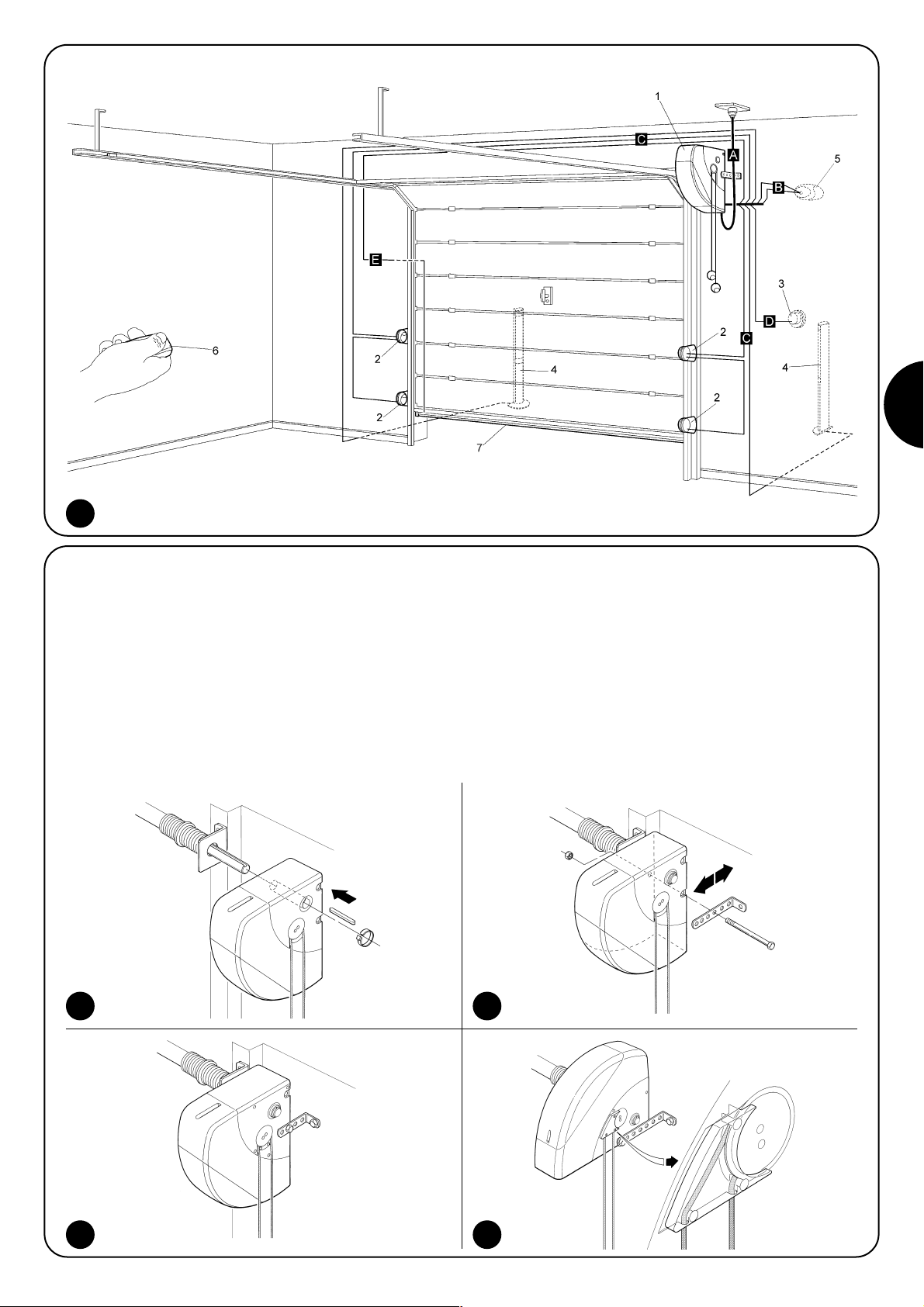
53
D
4.2) Die mechanischen bestandteile installieren
Nachdem die Vorbereitungsarbeiten zur Installation (wie z.B. Ausgraben der Kanäle zum Verlegen der Elektrokabel oder Verlegen
externer Kanäle; eventuelle Befestigung der genannten Kanäle im
Beton und andere notwendige Vorbereitungen) beendet sind, können die Montage und die vollständige Installation aller
mechanischen und elektrischen Teile des Soon ausgeführt werden.
In der hier angegebenen Reihenfolge weiterarbeiten.
Montage des Antriebs Soon (siehe Abb. 4)
1. (Abb. 4-a) Die Ausgangswelle des Soon in die Antriebswelle des
Sektionaltors stecken und mit Hilfe eins mitgelieferten Keils verbinden.
Diesen Vorgang bei GESCHLOSSENEM Tor ausführen
2. (Abb. 4-b) Am Soon, den Bügel mit Schraube, Mutter und Unterlegscheibe (mitgeliefert) befestigen.
3. (Abb. 4-c) Den Bügel mit einem für das Mauermaterial geeigneten Dübel (nicht mitgeliefert) an der Wand befestigen.
4. (Abb. 4-d) Soon kann mit Hilfe des speziellen Vorgeleges (mitgeliefert) in horizontaler Stellung befestigt werden. Das Vorgelege
muss mit drei Schrauben (mitgeliefert) in der dargestellten Position befestigt werden. Achtung: den Austritt der Entriegelungsseile beachten.
4a 4b
4c 4d
3
Page 54

54
4.3) Die elektrischen kabel verlegen (siehe Abb. 3 und Tab. 1)
Nach der Installation der verschiedenen mechanischen Bestandteile, alle notwendigen Elektrokabel verlegen - siehe Abb. 3 mit der typischen
Anordnung dieser Kabel, und die Tabelle 1, die ihre technischen Merkmale vereinzelt analysiert.
Die für den Anschluss der verschiedenen Vorrichtungen benutzten Kabel müssen für den auszuführenden Installationstyp geeignet sein: wenn die Installation in einem überdachten Raum oder in einem Gebäude erfolgt, wird ein Kabel
des Typs H03VV-F empfohlen.
MERKMALE DER ELEKTRISCHEN KABEL
(Die mit den Kabeln kombinierten Buchstaben sind dieselben wie in Abb. 3)
!
Anmerkungen: (*) Falls das Versorgungskabel länger als 30 m ist, muss ein Kabel mit größerem Durchschnitt benutzt werden (z.B.: und
eine Sicherheitserdung in der Nähe der Automatisierung ist erforderlich.
Anschluss Kabeltyp Zulässige Höchstlänge
A: Elektrische Versorgungsleitung Nr. 1 Kabel (3 x 1,5 mm2) 30 m (*)
B: Blinkleuchte Nr. 1 Kabel (2 x 1 mm2) 20 m
C: Antenne Nr. 1 abgeschirmtes Kabel (Typ RG58) 20 m (empfohlen: kürzer als 5m)
D: Photozelle Nr. 1 Kabel (2 x 0,5 mm2) 30 m
E: Schlüsseltaster Nr. 1 Kabel (4 x 0,5 mm2) 50 m
F: Bewegliche Schaltleisten Nr. 1 Kabel (2 x 0,5 mm2) 20 m
Tabelle 1: Kabelliste
4.4) Ver- und entriegelung von hand
Jedes Mal auf dieses Verfahren Bezug nehmen, wenn
im Text des Handbuchs gefordert wird, den Mechanismus
von SOON von Hand zu “verriegeln” oder zu “entriegeln.
Anmerkungen:
Ent- und Verriegelungsverfahren dürfen nur mit ganz stehendem
Antrieb ausgeführt werden.
• Das manuelle Verfahren muss bei einem Stromausfall, bei Störun-
gen der Anlage oder wann ausdrücklich im Text des Handbuchs
verlangt ausgeführt werden.
• Die manuelle Entriegelung ermöglicht den freien Lauf des Sektio-
naltors.
!
Zum Entriegeln: an Kugel A ziehen
Zum Verriegeln: an Kugel B ziehen
Um die Sicherheit des Installateurs zu gewährleisten und Schäden an den Bestandteilen der Automatisierung zu vermeiden, ist vor der Durchführung der elektrischen Anschlüsse oder dem Einstecken des Funkempfängers sicher zu stellen, dass die Steuerung vom Stromnetz und von eventuellen Pufferbatterien ABGETRENNT ist.
!
5) Die elektrischen Anschlüsse ausführen
5.1) Alle vorrichtungen anschließen
Alle elektrischen Anschlüsse müssen ohne Spannung zur Anlage
ausgeführt werden.
1. Um den Schutzdeckel zu entfernen und Zugang zur elektroni-
schen Steuerung von SOON zu erhalten, muss die Schraube entfernt und der Deckel nach oben herausgezogen werden (Abb. 5).
2. Den freien Kabelhalter lösen und die Kabel für den Anschluss an
den Klemmen der Steuerung durchführen. Die Kabel 20-30 cm
länger als notwendig lassen. Siehe die Tabelle Nr. 1 für den Kabeltyp und die Abbildung 6 für die Anschlüsse.
3. Den Anschluss der Kabel nach dem Schema in Abb. 7 ausführen.
Um die Anschlüsse zu erleichtern, sind die Klemmen abziehbar.
4. Die Kabel nach Beendigung der Anschlüsse durch Festziehen
des Kabelhalters blockieren. Der über-schüssige Teil des Antennekabels muss mit einer ande-ren Schelle an den anderen
Kabeln blockiert werden.
65
Page 55

55
D
7
FLASH Dieser Ausgang kann programmiert werden (siehe den ZWEITEN TEIL des Handbuchs), um eine der folgenden
Vorrichtungen daran anzuschließen:
Blinkleuchte Falls als “Blinkleuchte” programmiert, kann am Ausgang “FLASH” eine NICE Blinkleuchte “LUCY B” mit
12V 21W Lampe automatischen Typs angeschlossen werden.
Während der Bewegung blinkt sie in Abständen von 0,5 Sekunden (0,5 Sek. ein, 0,5 Sek. aus).
Ausgang “Kontrolllampe Tor geöffnet“ Falls als “Kontrolllampe Tor geöffnet“ programmiert, kann am Ausgang
“FLASH” eine 24V max. 5W Kontrolllampe für die Anzeige Tor geöffnet angeschlossen werden.
Kann auch für andere Funktionen programmiert werden - siehe den ZWEITEN TEIL des Handbuchs.
Saugscheibe* Falls als “Saugscheibe” programmiert, kann am Ausgang “FLASH” eine 24V max. 10W Saugscheibe angeschlossen werden (Ausführungen nur mit Elektromagnet, ohne elektronische Vorrichtungen). Wenn das Tor geschlossen ist,
aktiviert sich die Saugscheibe und blockiert das Tor. Während der Öffnungs- oder Schließbewegung wird sie deaktiviert.
Elektrosperre* Falls als “Elektrosperre” programmiert, kann am Ausgang “FLASH” eine Elektrosperre mit 24V max. 10W
Schnappschloss angeschlossen werden (Ausführungen nur mit Elektromagnet, ohne elektronische Vorrichtungen). Während
der Öffnungsbewegung aktiviert sich die Elektrosperre und bleibt aktiv, um das Tor frei zu machen, so dass die Bewegung
erfolgen kann. Bei der Schließbewegung ist sicher zu stellen, dass sich die Elektrosperre wieder mechanisch einspannt.
Elektroschloss* Falls als “Elektroschloss” programmiert, kann am Ausgang “FLASH” ein Elektroschloss mit 24V max.
10W Schnappschloss e angeschlossen werden (Ausführungen nur mit Elektromagnet, ohne elektronische Vorrichtungen).
Während der Öffnungsbewegung aktiviert sich das Elektroschloss kurz, um das Tor frei zu machen, so dass die Bewegung
erfolgen kann. Bei der Schließbewegung ist sicher zu stellen, dass sich das Elektroschloss wieder mechanisch einspannt.
BLUEBUS an dieser Klemme können kompatible Vorrichtungen angeschlossen werden; alle Vorrichtungen werden mit nur zwei Leitern,
auf denen sowohl die Stromversorgung als auch die Kommunikationssignale übermittelt werden, parallel geschaltet.
Weitere Auskünfte über BlueBUS sind in Par. “5.2 Die BlueBUS-Vorrichtungen anschließen” enthalten.
STOPP Eingang für Vorrichtungen, welche die laufende Bewegung blockieren oder ggf. anhalten; mit entsprechenden Maßnahmen am
Eingang können "gewöhnlich geschlossene“ und "gewöhnlich geöffnete“ Kontakte oder Vorrichtungen mit konstantem
Widerstand bzw. optische Vorrichtungen angeschlossen werden. Weitere Auskünfte über STOPP sind in Par. “5.3 - Vorrichtungen
am Eingang Stopp anschließen” enthalten.
PP Eingang für Vorrichtungen, welche die Bewegung in Modalität Schrittbetrieb steuern; es können “gewöhnlich geöffnete”
Kontakte angeschlossen werden.
OPEN Eingang für Vorrichtungen, die nur eine Öffnungsbewegung steuern; es können “gewöhnlich geöffnete” Kontakte
angeschlossen werden.
CLOSE Eingang für Vorrichtungen, die nur eine Schließbewegung steuern; es können “gewöhnlich geöffnete” Kontakte
angeschlossen werden.
ANTENNE Eingang für den Anschluss der Antenne für Funkempfänger (die Antenne ist in LUCY B eingebaut).
* Es können nur Vorrichtungen angeschlossen werden, die nur den Elektromagneten enthalten.
Keine anderen vorrichtungen als vorgesehen verwenden
!
Page 56
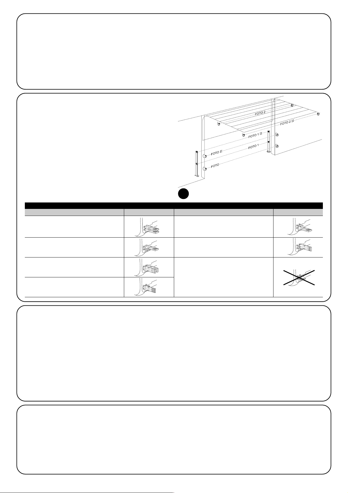
56
5.2) Die bluebus-vorrichtungen anschließen
BlueBUS ist eine Technik, mit der kompatible Vorrichtungen mit nur
zwei Leitern, auf denen sowohl die Stromversorgung als auch die
Kommunikationssignale übermittelt werden, angeschlossen werden
können. Alle Vorrichtungen werden an den 2 BlueBUS Leitern parallel geschaltet; eine Polung ist nicht zu beachten. Jede Vorrichtung
wird einzeln erkannt, da ihr während der Installation eine eindeutige
Adresse zugeteilt wird. An BlueBUS kann man zum Beispiel Photozellen, Sicherheitsvorrichtungen, Steuertasten, Leuchtmelder usw.
anschließen. Die Steuerung von SOON er-kennt nacheinander alle
angeschlossenen Vorrichtungen durch eine geeignete Erlernung und
ist imstande, alle möglichen Stö-rungen mit höchster Sicherheit
wahrzunehmen. Deshalb muss an der Steuerung jedes Mal, wenn
eine an BlueBUS angeschlossene Vorrichtung hinzugefügt oder entfernt wird, die Erlernphase aus-geführt werden, wie in Par. “7.1 Vorrichtungen speichern” be-schrieben.
5.2.2) Lichtsensor FT210B
Der Lichtsensor FT210B vereint in einer einzigen Vorrichtung das
Kraftbegrenzungssystem (Typ C gemäß EN12453) und einen Präsenzdetektor, der Hindernisse auf der optischen Achse zwischen
Sender TX und Empfänger RX wahrnimmt (Typ D gemäß EN12453).
Die Statussignale der Schaltleiste werden über den Strahl der Photozelle in den Lichtsensor FT210B gesendet, wodurch 2 Systeme in
einer einzigen Vorrichtung integriert sind. Der übertragende Teil am
beweglichen Torflügel ist durch Batterien gespeist, was unschöne
Anschlüsse verhindert; spezielle Kreisläufe verringern den Verbrauch
der Batterie, deren Dauer bis zu 15 Jahre lang garantiert wird (siehe
Details dieser Schätzung in den Anweisungen des Produkts).
Mit nur einer Vorrichtung FT201B, kombiniert mit einer Schaltleiste
(z.B. TCB65) kann das Sicherheitsniveau der "Hauptschaltleiste“
erreicht werden, das von Norm EN12453 für jede Art von "Benutzung“ und "Aktivierung“ verlangt ist. Der Lichtsensor FT210B in
Kombination mit resistiven Schaltleisten (8,2Kohm) ist vor einzelnen
Defekten geschützt (Klasse 3 gemäß EN 954-1). Er verfügt über
einen speziellen Antikollisionskreislauf, der Interferenzen mit anderen,
auch nicht synchronisierten Detektoren verhindert und die Hinzufügung weiterer Photozellen ermöglicht, wie zum Beispiel für die
Durchfahrt von schweren Fahrzeugen, wo gewöhnlich eine zweite
Photozelle in 1 m Höhe ab Boden angebracht wird. Für weitere Auskünfte über Anschluss und Adressierung wird auf die Anleitung von
FT210B verwiesen.
5.3) Vorrichtungen am eingang stopp anschließen
STOPP ist der Eingang, der das unverzügliche Anhalten der Bewegung verursacht, gefolgt von einer kurzen Umkehrung. An diesen
Eingang können Vorrichtungen mit Ausgang mit gewöhnlich geöffnetem “NO”-Kontakt, mit gewöhnlich geschlossenem “NC”-Kontakt
oder Vorrichtungen mit Ausgang mit konstantem 8,2KΩ Widerstand,
wie zum Beispiel Schaltleisten, oder optische Vorrichtungen angeschlossen werden.
Wie für BlueBUS, erkennt die Steuerung die am Eingang STOPP
angeschlossene Vorrichtung während der Erlernung - siehe Paragraph “7.1 Vorrichtungen speichern”; danach wird ein STOPP verursacht, wenn eine beliebige Variation des erlernten Status erfolgt.
Mit entsprechenden Maßnahmen kann am Eingang STOPP mehr als
eine Vorrichtung auch anderen Typs angeschlossen werden.
• Mehrere NO-Vorrichtungen können miteinander in unbegrenzter
Menge parallelgeschaltet werden.
5.2.1) Photozellen
Das System “BlueBUS” ermöglicht durch die Adressierung mit speziellen Überbrückungen die Erkennung der Photozellen seitens der
Steuerung und die Zuteilung der korrekten Wahrnehmungsfunktion.
Die Adressierung muss sowohl an TX als auch an RX ausgeführt
werden (wobei die Überbrückungen auf dieselbe Art anzuordnen
sind). Überprüft werden muss, dass andere Photozellenpaare nicht
dieselbe Adresse haben.
An einem Sektionaltorautomatismus mit SOON können die Photozellen wie auf Abbildung 8 gezeigt installiert werden. 8. Nach der
Installation oder Entfernung von Photozellen muss an der Steuerung
die Erlernphase ausgeführt werden, wie in Par. “7.1 - Vorrichtungen
speichern” beschrieben.
8
FOTO
Photozelle H = 50
mit Auslösung in Schließung;
FOTO II
Photozelle H = 100
mit Auslösung in Schließung;
FOTO 1
Photozelle H = 50 mit Auslösung sowohl in
Schließung als auch in Öffnung;
FOTO 1 II
Photozelle H = 50 mit Auslösung sowohl in
Schließung als auch in Öffnung;
FOTO 2
Photozelle
mit Auslösung in Öffnung
FOTO 2 II
Photozelle
mit Auslösung in Öffnung
FOTO 3
UNZULÄSSIGE KONFIGURATION
Tabelle 2: Adressierungen der Photozellen
Photozelle Überbrückungen Photozelle Überbrückungen
Page 57
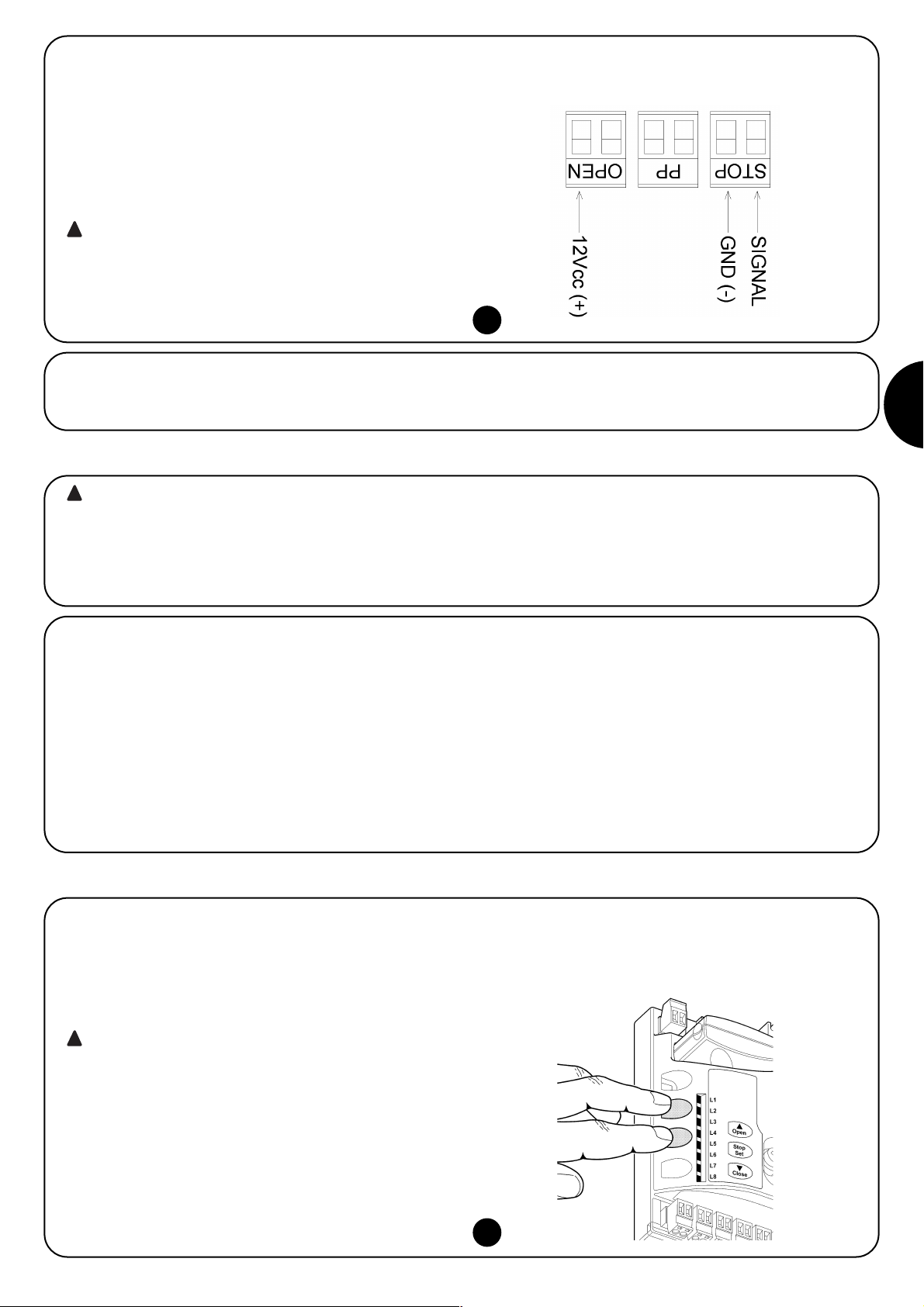
57
D
5.4) Die bluebus-vorrichtungen anschließen
Für die Versorgung von SOON mit Betriebsspannung genügt es, den Stecker von SOON in eine Steckdose zu stecken. Sollte der Stecker
von SOON nicht mit der verfügbaren Steckdose übereinstimmen, kann ein handelsüblicher Adapter benutzt werden.
• Mehrere NC-Vorrichtungen können miteinander in unbegrenzter
Menge seriengeschaltet werden.
•
Zwei Vorrichtungen mit konstantem 8,2KΩ Widerstand können parallelgeschaltet werden, im Falle von mehr als 2 Vorrichtungen müssen alle
mit nur einem 8,2KΩ Endwiderstand “kaskadengeschaltet” werden.
• Die Kombination NO und NC ist möglich, wenn die 2 Kontakte parallelgeschaltet werden, wobei ein 8,2KΩ Widerstand mit dem NCKontakt seriengeschaltet werden muss (daher ist auch die Kombination von 3 Vorrichtungen NO, NC und 8,2KΩ möglich)
Falls der Eingang STOPP für den Anschluss von Vorrichtungen mit Sicherheitsfunktionen benutzt wird, garantieren nur die Vorrichtungen mit Ausgang mit konstantem
8,2KΩ Widerstand oder optische Vorrichtungen OPTO
SENSOR die Sicherheitsklasse 3 gegen Defekte gemäß
der Vorschrift EN 954-1.
Für den Anschluss einer optischen Vorrichtung des Typs OPTO
SENSOR sind die Verbindungen hingegen wie in Abb. 9 gezeigt auszuführen. 9:
!
9
Die hier folgenden Arbeiten werden an unter Spannung stehenden elektrischen Kreisläufen ausgeführt, die Vorgänge könnten daher gefährlich sein! Daher sehr vorsichtig und nie allein vorgehen.
Nachdem die Installation der Bestandteile und der elektrische Anschluss beendet sind, müssen sofort einige einfache Überprüfungen des
korrekten Betriebs der Anlage ausführt werden, bevor weitergemacht wird. Dann die hier folgend verzeichneten Vorgänge ausführen und die
Punkte nach der Überprüfung der Konformität der Ergebnisse nach und nach abhaken.
!
6) Erstes Einschalten der Anlage - Überprüfungen
7) Vorrichtungen und Positionen speichern
6.1) Betriebstest
Sobald SOON mit Spannung versorgt ist, sollten einige einfache
Überprüfungen ausgeführt werden:
K Prüfen, ob die BlueBUS-Led regelmäßig einmal pro Sekunde
blinkt.
K Falls Photozellen vorhanden sind, prüfen, dass auch die LEDs an
den Photozellen (sowohl an TX als auch an RX) blinken; wie die
LEDs blinken, ist unwichtig und hängt von anderem ab.
K Prüfen, dass die an Ausgang FLASH angeschlossene Vorrich-
tung ausgeschaltet ist.
K Prüfen, dass die zusätzliche Beleuchtung ausgeschaltet ist.
Sollte all dies nicht der Fall sein, muss die Versorgung zur Steuerung
unverzüglich ausgeschaltet werden, dann die elektrischen Anschlüsse genauer kontrollieren.
7.1) Vorrichtungen speichern
Nach dem Anschluss der Versorgung muss die Steuerung die an
den Eingängen BlueBUS und STOP angeschlossenen Vorrichtungen
erkennen. Vor dieser Phase blinken die LEDs L1 und L2 und geben
somit an, dass die Erlernung der Vorrichtungen ausgeführt werden
muss.
Die Erlernungsphase der Vorrichtungen muss auch,
wenn keine Vorrichtung angeschlossen ist, ausgeführt
werden.
1. Auf die Tasten [▲] und [Set] drücken und gedrückt halten
2. Die Tasten loslassen, wenn die LEDs L1 und L2 sehr schnell zu
blinken beginnen (nach ca. 3 Sekunden)
3. Ein paar Sekunden warten, bis die Steuerung die Erlernung der
Vorrichtungen beendet.
4. Am Ende der Erlernung muss die LED STOPP eingeschaltet blei-
ben; die LEDs L1 und L2 werden sich ausschalten (eventuell
werden L3 und L4 zu blinken beginnen)
Die Erlernphase der angeschlossenen Vorrichtungen kann jederzeit
auch nach der Installation wiederholt werden, wenn zum Beispiel
eine Vorrichtung hinzugefügt wird.
!
10
Page 58

58
7.2) Positionen speichern
Nach der Erlernung der Vorrichtungen muss die Steuerung die Öffnungs- und Schließpositionen des Tors erkennen. Man kann bis zu 6 Positionen programmieren. Sie sind:
Position Bedeutung
A1 Maß der gewünschten, maximalen Öffnung. Das Tor hält an, wenn es diese Position erreicht.
RA1 Maß, an dem die Verlangsamung in Öffnung beginnt. Wenn das Tor diese Position erreicht, geht der Motor auf die
Mindestgeschwindigkeit herunter.
RINT Zwischenmaß für die Verlangsamung in Schließung. Wenn man diese Position programmiert, wird das Tor die
Verlangsamung ca. 50 cm vorher beginnen und die Position RINT mit Mindestgeschwindigkeit durchlaufen. Nachdem es
das Maß RINT durchlaufen hat, wird sich der Motor wieder auf die programmierte Geschwindigkeit bringen.
AP Teilöffnungsmaß. Ist die Position, in der das Tor anhält, wenn ein Befehl für Teilöffnung gegeben wird.
RA0 Maß, an dem die Verlangsamung in Schließung beginnt. Wenn das Tor diese Position erreicht, geht der Motor auf die
Mindestgeschwindigkeit herunter.
A0 Maß der maximalen Schließung. Das Tor hält an, wenn es diese Position erreicht.
Die LEDs L3 und L4 blinken, wenn die Maße nicht erfasst sind.
Hier folgend ist das Speicherverfahren der Positionen beschrieben. Die Maße A1 und A0 müssen programmiert sein, wogegen die anderen
Positionen übersprungen werden können. Die Steuerung wird sie in diesem Fall automatisch berechnen.
1. 3 Sekunden lang auf [Set] + [▼] drücken, um in Speicherung der Maße zu gehen.
Die LED L1 blinkt: Programmierung von Maß A1
2. Das Tor mit den Tasten [▲] oder [▼] bis zur Position “maximale Öffnung” verschieben.
3. Sekunden lang auf Taste [Set] drücken, um das Maß A1 zu bestätigen. Die LED L1 bleibt eingeschaltet.
Die LED L2 blinkt: Programmierung von Maß RA1
4. Wenn man das Verlangsamungsmaß in Öffnung nicht programmieren will, 2 Mal schnell auf Taste [Set] drücken, um auf die
nächste Programmierung überzugehen; die LED L2 bleibt ausgeschaltet. Andernfalls in der angegebenen Reihenfolge weitermachen.
5. Das Tor mit den Tasten [▲] oder [▼] bis zur Position “Verlangsamung in Öffnung” verschieben.
6. 2 Sekunden lang auf Taste [Set] drücken, um das Maß RA1 zu bestätigen. Die LED L2 bleibt eingeschaltet.
Die LED L4 blinkt: Programmierung von Maß RINT
7. Wenn man das Verlangsamungszwischenmaß nicht programmieren will, 2 Mal schnell auf Taste [Set] drücken, um auf die nächste
Programmierung überzugehen; die LED L4 bleibt ausgeschaltet. Andernfalls in der angegebenen Reihenfolge weitermachen.
8. Das Tor mit den Tasten [▲] oder [▼] bis zur Verlangsamung-Zwischenposition verschieben.
9. 2 Sekunden lang auf Taste [Set] drücken, um das Maß RINT zu bestätigen. Die LED L4 bleibt eingeschaltet.
Die LED L5 blinkt: Programmierung von Maß RAP
10. Wenn man das Teilöffnungsmaß nicht programmieren will, 2 Mal schnell auf Taste [Set] drücken, um auf die nächste
Programmierung überzugehen; die LED L5 bleibt ausgeschaltet. Andernfalls in der angegebenen Reihenfolge weitermachen.
11. Das Tor mit den Tasten [▲] oder [▼] bis zur Position “Teilöffnung” verschieben.
12. 2 Sekunden lang auf Taste [Set] drücken, um das Maß RAP zu bestätigen. Die LED L5 bleibt eingeschaltet.
Die LED L7 blinkt: Programmierung von Maß RA0
13. Wenn man das Verlangsamungsmaß in Schließung nicht programmieren will, 2 Mal schnell auf Taste [Set] drücken, um auf die
nächste Programmierung überzugehen; die LED L7 bleibt ausgeschaltet. Andernfalls in der angegebenen Reihenfolge weitermachen.
14. Das Tor mit den Tasten [▲] oder [▼] bis zur Position “Verlangsamung in Schließung” verschieben.
15. 2 Sekunden lang auf Taste [Set] drücken, um das Maß RA0 zu bestätigen. Die LED L7 bleibt eingeschaltet.
Die LED L8 blinkt: Programmierung von Maß A0
16. Das Tor mit den Tasten [▲] oder [▼] bis zur Position “maximale Schließung” verschieben.
17. 2 Sekunden lang auf Taste [Set] drücken, um das Maß A0 zu bestätigen. Die LED L8 bleibt eingeschaltet.
18. Wenn man die Taste [Set] loslässt, schalten sich alle LEDs aus.
19. Auf Taste [Open] drücken, um einen Öffnungsbefehl zu erteilen und eine vollständige Öffnungsbewegung auszuführen.
20. Auf Taste [Close] drücken, um einen Schließbefehl zu erteilen und eine vollständige Schließbewegung auszuführen.
Bei diesen Bewegungen speichert die Steuerung die zu den Öffnungs- und Schließbewegungen notwendige Kraft.
Wichtig: diese ersten Bewegungen dürfen z.B. mit einem
STOPP-Befehl nicht unterbrochen werden.
Die Erlernung der Positionen kann jederzeit auch nach der Installation wiederholt werden; es genügt, sie ab Punkt 1 erneut auszuführen. Wenn dagegen nur ein Maß geändert werden muss, die
Sequenz ab Punkt 1 wiederholen und die Programmierung jeder
betreffenden Position durch 2-maliges schnelles Drücken der Taste
[Set] überspringen.
11
Page 59

59
D
8) Die Endabnahme der Anlage ausführen
8.1) Test für die endabnahme
Für jedes einzelne Element des Automatismus wie zum
Beispiel Schaltleisten, Photozellen, Notstops usw. ist eine
spezielle Abnahmephase erforderlich; für diese Vorrichtungen sind die Verfahren in den jeweiligen Anleitungen
auszuführen. Für die Abnahme von SOON muss die folgende Sequenz an Vorgängen ausgeführt werden:
1. Prüfen, ob alles in Kapitel 1 “HINWEISE” angegebene genauestens eingehalten ist.
2. Das Tor vom Motor entriegeln, indem das Entriegelungsseil nach
unten gezogen wird. Prüfen, ob es möglich ist, das Tor in Öffnung und Schließung mit einer Kraft nicht über 225N von Hand
zu bewegen.
3. Das Tor wieder mit dem Motor verriegeln, indem am Verriegelungsseil gezogen wird.
4. Den Schlüsseltaster oder Funksender verwenden, die
Schließung und Öffnung des Tors testen und prüfen, ob die
Bewegung wie vorgesehen ist.
5. Besser mehrere Tests ausführen, um das Gleiten des Tors und
eventuelle Montage- und Einstellfehler sowie das Vorhandensein
besonderer Reibungen zu überprüfen.
6. Den korrekten Betrieb aller Sicherheitsvorrichtungen der Anlage
einzeln überprüfen (Photozellen, Schaltleisten usw.). Bei jeder
Auslösung einer Vorrichtung wird die BlueBUS-LED an der
Steuerung zweimal schneller blinken und so bestätigen, dass die
Steuerung das Ereignis erkannt hat.
7. Zur Überprüfung der Photozellen und insbesondere um zu prüfen, dass keine Interferenzen mit anderen Vorrichtungen vorhanden sind, einen 30 cm langen Zylinder mit 5 cm Durchmesser auf
der optischen Achse zuerst nah an TX, dann nah an RX und
abschließend in ihrer Mitte durchführen (siehe Abbildung 15) und
prüfen, dass die Vorrichtung in allen Fällen ausgelöst wird und
vom aktiven Zustand auf den Alarmzustand übergeht und umgekehrt; abschließend prüfen, dass in der Steuerung die vorgesehene Handlung erfolgt, wie zum Beispiel: während der
Schließung also zum Beispiel eine Umkehrung der Bewegung.
8. Falls die durch die Torbewegung verursachten Gefahren mittels
Begrenzung der Aufprallkraft abgesichert worden sind, muss die
Kraft nach den Verordnungen der Vorschrift EN 12445 gemessen werden. Falls die « Geschwindigkeitsregelung“ und die Kontrolle der “Motorkraft” als Hilfsmittel für das System zur Aufprallkraftreduzierung benutzt wird, die Einstellung erproben und finden, mit der die besten Ergebnisse erzielt werden.
8.2) Inbetriebsetzung
Die Inbetriebsetzung darf erst erfolgen, nachdem alle Abnahmephasen von Soon sowie der anderen Vorrichtungen
erfolgreich beendet sind. Eine teilweise oder vorübergehende Inbetriebsetzung ist unzulässig.
1. Die technischen Unterlagen der Automatisierung zusammenstellen und diese mindestens 10 Jahre lang aufbewahren. Sie müssen mindestens umfassen: Gesamtzeichnung der Automatisierung, Schaltplan mit den elektrischen Anschlüssen, Risikoanalyse und jeweilige angewendete Lösungen, Konformitätserklärung
des Herstellers für alle benutzten Vorrichtungen (für Soon die
anliegende “CE-Konformitätserklärung” verwenden), Kopie der
Bedienungsanweisungen und des Wartungsplans der Automatisierung.
2. Am Tor ein Schild mit mindestens folgenden Daten anbringen:
Automatisierungstyp, Name und Adresse des Herstellers (Verantwortlicher der “Inbetriebsetzung”), Seriennummer, Baujahr
und CE-Markierung.
3. In Tornähe auf bleibende Art ein Etikett oder ein Schild befestigen, dass die Angaben zur Durchführung der Entriegelung und
der Bewegung von Hand enthält.
4. Am Tor auf bleibende Weise ein Etikett oder Schild mit dieser
Abbildung befestigen (Mindesthöhe 60 mm).
5. Die Konformitätserklärung der Automatisierung anfertigen und
dem Inhaber aushändigen.
6. Das Handbuch "Anweisungen und Hinweise für die Bedienung
der Automatisierung“ anfertigen und dem Inhaber der Automatisierung übergeben.
7. Den Wartungsplan anfertigen und dem Inhaber der Automatisierung aushändigen. Er enthält die Wartungsvorschriften der einzelnen Vorrichtungen.
8. Vor der Inbetriebsetzung des Automatismus, den Inhaber auf
geeignete Weise und schriftlich (z.B. in den "Anweisungen und
Hinweise für die Bedienung der Automatisierung“ über die noch
vorhandenen Gefahren und Risiken informieren.
Page 60

60
Im ZWEITEN TEIL des Handbuchs wird beschrieben, wie die Automatisierung durch Einstellungen und Optionen, die in der Steuerung gespeichert werden, personalisiert werden kann. Ein Endabschnitt des Handbuchs ist dagegen den Problemen und ihrer Lösung sowie der Wartung und Entsorgung des Produktes gewidmet.
9) Anweisungen für die Personalisierung der Automatisierung
Die Steuerung von SOON verfügt über einige programmierbare
Funktionen; die Einstellung dieser Funktionen erfolgt mit 3 Tasten an
der Steuerung: [▲] [Set] [▼]; die Funktionen werden über 8 LEDs
angezeigt: L1….L8.
Die an SOON zur Verfügung stehenden programmierbaren Funktionen befinden sich auf 2 Niveaus:
Erstes Niveau: ON-OFF-Funktionen (aktiv oder nicht aktiv); in diesem Fall zeigt jede LED L1É.L8 eine Funktion an; wenn die LED
leuchtet, ist die Funktion aktiviert, wenn die LED nicht leuchtet, ist
die Funktion deaktiviert - siehe Tabelle Nr. 3.
Zweites Niveau: auf einer Werteskala von 1 bis 8 einstellbare Parameter; in diesem Fall zeigt jede LED L1É.L8 den unter den 8 möglichen eingestellten Wert an - siehe Tabelle Nr. 4.
10) Programmierungen
Mit Taste “OPEN” kann dem Tor ein Öffnungsbefehl erteilt werden oder sie
dient zur Verschiebung des Programmierungspunktes nach oben.
Mit Taste “STOP” kann die Bewegung angehalten werden; falls länger als
5 Sekunden gedrückt, ermöglicht sie den Zugriff auf die Programmierung.
Mit Taste “CLOSE“ kann dem Tor ein Schließbefehl erteilt werden oder sie
dient zur Verschiebung des Programmierungspunktes nach unten.
9.1) Programmierungstasten
An der Steuerung von SOON sind 3 Tasten vorhanden, die sowohl zur Schaltung der
Steuerung bei den Tests als auch zu Programmierungen benutzt werden können:
12
OPEN
▲
STOP
SET
CLOSE
▼
LED Funktion Beschreibung
L1 Automatische Diese Funktion ermöglicht eine automatische Torschließung nach der programmierten Pausezeit; werkseitig ist die
Schließung Pausezeit auf 30 Sekunden eingestellt, kann aber auf 10, 20, 40, 60, 80, 120, 160 und 200 Sekunden geändert
werden. Wenn die Funktion nicht aktiviert ist, ist die Funktionsweise “halbautomatisch”.
L2 Zulauf nach Diese Funktion ermöglicht es, das Tor nur in der zur Durchfahrt nötigen Zeit geöffnet zu halten. In der Tat verursacht die
Durchfahrt Auslösung von « Foto » immer ein automatisches erneutes Schließen mit einer Pausezeit von 5 Sekunden (unabhängig
der Photozelle vom programmierten Wert). Das Verhalten ändert sich je nachdem, ob die Funktion « Automatische Schließung” aktiviert
ist oder nicht.
Mit deaktivierter “Automatischer Schließung”: Das Tor erreicht immer die Position ganz geöffnet (auch wenn d
ie Photozelle vorher frei wird). Beim Freiwerden der Photozelle wird der automatische Zulauf mit einer Pause von 5
Sekunden verursacht.
Mit aktivierter “Automatischer Schließung”: die Öffnungsbewegung stoppt gleich nach dem Freiwerden der
Photozellen und es wird der automatische Zulauf mit einer Pause von 5 Sekunden verursacht.
Die Funktion "Zulauf nach Durchfahrt der Photozelle“ wird im Falle von Bewegungen, die mit einem Stoppbefehl
unterbrochen wurden, immer deaktiviert. Wenn die Funktion "Zulauf nach Durchfahrt der Photozelle“ nicht aktiviert ist,
wird die Pausezeit wie programmiert sein, oder es erfolgt kein automatischer Zulauf, wenn die Funktion nicht aktiviert war.
L3 Schließt immer Die Funktion “Schließt Immer” wird ausgelöst und verursacht eine Schließung, wenn nach einem Stromausfall und
der Rückkehr der Stromversorgung das geöffnete Tor wahrgenommen wird. Aus Sicherheitsgründen geht der
Bewegung eine Vorwarnung von 3 Sekunden voraus. Wenn die Funktion nicht aktiviert ist, wird das Tor nach der
Rückkehr der Stromversorgung stehen bleiben.
L4 Stand-By Mit dieser Funktion kann der Verbrauch auf das Geringste reduziert werden. Wenn diese Funktion aktiviert ist,
schaltet die Steuerung 1 Minute nach Beendigung der Bewegung den Ausgang BlueBUS (und daher alle
Vorrichtungen) sowie alle LEDs mit Ausnahme der BlueBUS-LED aus, die langsamer blinken wird. Wenn die
Steuerung einen Befehl erhält, geht sie wieder auf den Normalbetrieb über. Wenn die Funktion deaktiviert ist, erfolgt
keine Reduzierung des Stromverbrauchs.
L5 Lange Mit dieser Funktion kann der Reversierungstyp gewählt werden, den das Tor aufgrund der Auslösung von STOPP
Reversierung oder des Kraftbegrenzers ausführt. Bei deaktivierter Funktion ist die Reversierung kurz (ca. 15 cm). Wenn die
Funktion aktiviert ist, erfolgt die Reversierung bis zum maximalen Maß i n Öffnung oder Schließung.
L6 Vorwarnen Mit der Vorwarnfunktion wird eine 3 Sekunden lange Pause zwischen Einschalten der Blinkleuchte und
Bewegungsbeginn erfolgen, um die Gefahr vorab bekannt zu geben. Wenn die Vorwarnfunktion nicht aktiviert ist,
erfolgen Einschalten der Blinkleuchte und Bewegungsbeginn gleichzeitig.
L7 Empfindlichkeit Mit dieser Funktion kann die Empfindlichkeit des Antriebs bei der Wahrnehmung von Hindernissen bedeutend
erhöht werden. Falls als Hilfe zur Aufprallkraftmessung benutzt, sind auch die Parameter „Geschwindigkeit“ und
“Motorkraft“ im Menü zweiten Niveaus einzustellen.
L8 Ausgleich Mit dieser Funktion kann die Dehnung der Metallseile des Tors im Laufe der Zeit ausgeglichen werden; sie untersteht
der Anwendung einer restitiven Schaltleiste des Typs 8,2KΩ oder einer optischen Schaltleiste des Typs OSE.
Während des Normalbetriebs von SOON0 sind die LEDs L1….L8 nach dem Status der Funktion, die sie darstellen, ein- oder ausgeschaltet, zum Beispiel ist L1 eingeschaltet, wenn die Funktion “Automatische Schließung” aktiviert ist.
Tabelle 3: Liste der programmierbaren Funktionen: erstes Niveau
10.1) Funktionen des ersten niveaus
Page 61

61
D
Pausezeit
Funktion
Schrittbetrieb
Motorgeschwindigkeit
Ausgang
FLASH
Motorkraft in
Öffnung
Motorkraft in
Schließung
L1
L2
L3
L4
L5
L6
L7
L8
L1
L2
L3
L4
L5
L6
L7
L8
L1
L2
L3
L4
L5
L6
L7
L8
L1
L2
L3
L4
L5
L6
L7
L8
L1
L2
L3
L4
L5
L6
L7
L8
L1
L2
L3
L4
L5
L6
L7
L8
10 Sekunden
20 Sekunden
40 Sekunden
60 Sekunden
80 Sekunden
120 Sekunden
160 Sekunden
200 Sekunden
Öffnet - Stop - Schließt - Stop
Öffnet - Stop - Schließt - Öffnet
Öffnet - Schließt - Öffnet - Schließt
Wohnblockbetrieb
Wohnblockbetrieb 2 (mehr als 2” bewirkt Stop)
Schrittbetrieb 2 (weniger als 2” bewirkt Gehflügel)
Todmannfunktion
Öffnung “halbautomatisch”, Schließung mit “Todmannfunktion”
Geschwindigkeit 1 (30% - langsam)
Geschwindigkeit 2 (44%)
Geschwindigkeit 3 (58%)
Geschwindigkeit 4 (72%)
Geschwindigkeit 5 (86%)
Geschwindigkeit 6 (100% - schnell)
Öffnet V4, schließt V2
Öffnet V6, schließt V4
Kontrolllampe Tor Geöffnet
Aktiv, wenn das Tor geschlossen ist
Aktiv, wenn das Tor geöffnet ist
Blinkleuchte
Elektrosperre
Elektroschloss
Saugscheibe
Leuchtmelder Wartung erforderlich
Kraft 1 (niedrig)
Kraft 2
Kraft 3
Kraft 4
Kraft 5
Kraft 6
Kraft 7
Kraft 8 (hoch)
Kraft 1 (niedrig)
Kraft 2
Kraft 3
Kraft 4
Kraft 5
Kraft 6
Kraft 7
Kraft 8 (hoch)
10.3) Funktionen des zweiten niveaus (einstellbaren Parameter)
Tabelle 4: Liste der programmierbaren Funktionen: zweites Niveau
Eingangs- LED Parameter LED (Niveau) Wert Beschreibung
Stellt die Pausezeit ein bzw.
die Zeit vor dem automatischen Zulauf. Wirkt nur, falls
die automatische
Schließung aktiviert ist.
Stellt die Sequenz der Steuerbefehle ein, die dem Eingang Schrittbetrieb oder
dem 1. Funkbefehl zugeteilt
sind.
Stellt die Motorgeschwindigkeit während des normalen Laufs ein
Wählt die an Ausgang
FLASH angeschlossene
Vorrichtung
Regelt das Kontrollsystem
der Motorkraft, um sie
während der Öffnungsbewegung dem Tortyp anzupassen.
Regelt das Kontrollsystem
der Motorkraft, um sie
während der Schließbewegung dem Tortyp anzupassen.
Anmerkung: “ ” ist die werkseitige Einstellung SEGUE
L1
L2
L3
L4
L5
L6
10.2) Programmierungen des ersten niveaus
Werkseitig sind alle Funktionen des ersten Niveaus auf “OFF” gestellt, was aber jederzeit geändert werden kann, wie hier folgend beschrieben. Bei der Durchführung des Verfahrens vorsichtig sein, da die Zeitgrenze 10s zwischen dem Druck auf eine Taste und die andere beträgt.
Andernfalls wird das Verfahren automatisch beendet, mit Speicherung der bisher ausgeführten Änderungen.
10s warten, um die Programmierung aufgrund des Ablaufs der Zeitgrenze zu beenden.
Anmerkung: die Punkte 3 und 4 können während derselben Programmierungsphase wiederholt werden, um andere Funktionen auf ON
oder OFF zu stellen.
1. Auf Taste [Set] drücken und ca. 3 Sekunden gedrückt halten
2. Ta st e [Set] loslassen, wenn LED L1 zu blinken beginnt
3. Auf Taste [▲] oder [▼] drücken, um das Blinken auf die LED zu verschieben, welche die zu ändernde Funktion darstellt
4. Auf Taste [Set] drücken, um den Status der Funktion zu ändern (kurzes Blinken = OFF; langes Blinken = ON)
Page 62

62
SOON warnt den Benutzer, wann eine Wartung der Automatisierung ausgeführt werden soll. Die Anzahl an Bewegungen, nach der die Anzeige erfolgt, kann im einstellbaren Parameter “Wartungsanzeige” (siehe Tabelle 4) auf 8
Niveaus ausgewählt werden. 4).
Das Niveau 1 ist “automatisch” und berücksichtigt die Beschwerlichkeit der Bewegungen bzw. den Kraftaufwand und die Dauer der
Bewegung, wogegen die anderen Niveaus von der Anzahl der
Bewegungen ausgehen.
Die Anzeige “Wartung notwendig” erfolgt durch die Blinkleuchte oder
die Wartungskontrolllampe, je nach Programmierung (siehe Tab. 4).
Je nach Anzahl an ausgeführten Bewegungen im Vergleich zum programmierten Grenzwert geben die Blinkleuchte Flash und die Wartungskontrolllampe die in Tabelle 5 angegebenen Anzeigen ab. 5.
11) Wartungsanzeige
Wartungsanzeige
Liste der
Störungen
L1
L2
L3
L4
L5
L6
L7
L8
L1
L2
L3
L4
L5
L6
L7
L8
Automatisch (je nach Beschwerlichkeit der Bewegungen)
1.000
2.000
4.000
6.000
8.000
10.000
12.000
Ergebnis 1. Bewegung (die letzte)
Ergebnis 2. Bewegung
Ergebnis 3. Bewegung
Ergebnis 4. Bewegung
Ergebnis 5. Bewegung
Ergebnis 6. Bewegung
Ergebnis 7. Bewegung
Ergebnis 8. Bewegung
Eingangs- LED Parameter LED (Niveau) Wert Beschreibung
Regelt die Anzahl an
Bewegungen, nach der die
Anzeige « Wartung der
Automatisierung
erforderlich“ erscheinen soll
(siehe Par. “13
Wartungsmeldung”).
Zur Überprüfung der
Störung, die bei den 8
letzten Bewegungen
erfolgte (siehe Par. “14
Alarmhistorik”).
Anmerkung: “ ” ist die werkseitige Einstellung
Alle Parameter können beliebig ohne Nebenwirkungen eingestellt werden, nur für die Einstellung der “Motorkraft in Öffnung” und “Motorkraft
in Schließung” könnte besondere Aufmerksamkeit geboten sein:
• Keine hohen Kraftwerte benutzen, um der Tatsache abzuhelfen, dass das Tor starke Reibungspunkte hat. Eine zu starke Kraft kann das
Sicherheitssystem beeinträchtigen und das Tor beschädigen.
• Falls die Kontrolle der “Motorkraft” als Hilfsmittel für das System zur Aufprallkraftreduzierung benutzt wird, die Kraftmessung nach jeder Einstellung wiederholen, wie von Norm EN 12445 vorgesehen.
• Verschleiß und Witterung können die Torbewegungen beeinflussen; die Krafteinstellung sollte in regelmäßigen Abständen überprüft werden.
L7
L8
10.4) Programmierungen zweiten niveaus
Werkseitig sind die einstellbaren Parameter wie in Tabelle Nr. 4 mit “ ” angegeben eingestellt, sie können aber wie hier folgend beschrieben jederzeit geändert werden. Bei der Durchführung des Verfahrens vorsichtig sein, da die Zeitgrenze 10s zwischen dem Druck auf eine
Taste und die andere beträgt. Andernfalls wird das Verfahren automatisch beendet, mit Speicherung der bisher ausgeführten Änderungen.
10s warten, um die Programmierung aufgrund des Ablaufs der Zeitgrenze zu beenden.
Anmerkung: die Punkte von 3 bis 7 können während derselben Programmierungsphase wiederholt werden, um mehrere Parameter einzustellen.
1. Auf Taste [Set] drücken und ca. 3 Sekunden gedrückt halten
2. Ta st e [Set] loslassen, wenn LED L1 zu blinken beginnt
3. Auf Taste [▲] oder [▼] drücken, um das Blinken auf die “Eingangs-LED“ zu verschieben, die den zu ändernden Parameter darstellt
4. Auf Taste [Set] drücken und gedrückt halten; die Taste [Set] muss während der Schritte 5 und 6 ständig gedrückt bleiben
5. Ca. 3s warten, danach wird die LED aufleuchten, die das aktuelle Niveau des zu ändernden Parameters darstellt
6. Auf Taste [▲] oder [▼] drücken, um die LED zu verschieben, die den Wert des Parameters darstellt.
7. Die Taste [Set] loslassen
Anzahl an Bewegungen Anzeige an Flash Anzeige an Wartungskontrolllampe
Unter 80% des Grenzwertes Normal (0,5 Sek. ein, 0,5 Sek. aus). Ein für 2 Sek. bei Öffnungsbeginn
Zwischen 81 und 100% des Bleibt bei Öffnungsbeginn 2 Sek. eingeschaltet, blinkt dann Blinkt während der ganzen Grenzwertes
Bewegung. normal weiter
Über 100% des Grenzwertes Bleibt bei Bewegungsbeginn und am Ende der Bewegung Blinkt immer
2 Sek. eingeschaltet, blinkt dann normal weiter
Tabelle 5: Wartungsanzeige mit Flash und Wartungskontrolllampe
Page 63

63
D
11.1) Überprüfung der anzahl an ausgeführten bewegungen
Mit der Funktion “Wartungsanzeige” kann die Anzahl an ausgeführten Bewegungen als Prozentsatz des eingestellten Grenzwertes überprüft
werden. Die Überprüfung wie hier folgend beschrieben ausführen.
1. Auf Taste [Set] drücken und ca. 3 Sekunden gedrückt halten
2. Ta st e [Set] loslassen, wenn LED L1 zu blinken beginnt
3. Auf Taste [▲] oder [▼] drücken, um das Blinken auf die LED L7, die “Eingangs-LED“ des Parameters “Wartungsanzeige” zu verschieben
4. Auf Taste [Set] drücken und gedrückt halten; die Taste [Set] muss während der Schritte 5, 6 und 7 ständig gedrückt bleiben
5. Ca. 3s warten, danach wird die LED aufleuchten, die das aktuelle Niveau des Parameters "Wartungsanzeige“ darstellt
6. Auf die Tasten [▲] und [▼] drücken und sofort loslassen.
7. Die LED, die dem gewählten Niveau entspricht, wird mehrmals blinken. Die Anzahl an Blinkvorgängen steht für den Prozentsatz an
ausgeführten Bewegungen (Vielfaches von 10%) im Vergleich zum eingestellten Grenzwert. Beispiel: eingestellt ist die
Wartungsanzeige an L7 mit 10000. 10% entspricht 1000 Bewegungen. Wenn die LED vier Mal blinkt, ist 40% der Bewegungen
erreicht worden (zwischen 4000 und 4999 Bewegungen). Unter 10% der Bewegungen erfolgt kein Blinken.
8. Die Taste [Set] loslassen
SOON ermöglicht es, eventuelle Störungen bei den 8 letzten Bewegungen zu sehen, wie z.B. die Unterbrechung einer Bewegung infolge der
Auslösung einer Photozelle oder Schaltleiste. Um die Liste der Alarmhistorik zu überprüfen, wie hier folgend beschrieben vorgehen.
1. Auf Taste [Set] drücken und ca. 3 Sekunden gedrückt halten
2. Ta st e [Set] loslassen, wenn LED L1 zu blinken beginnt
3. Auf Taste [▲] oder [▼] drücken, um das Blinken auf die LED L8, die “Eingangs-LED“ des Parameters “Alarmhistorik” zu verschieben
4. Auf Taste [Set] drücken und gedrückt halten; die Taste [Set] muss während der Schritte 5 und 6 ständig gedrückt bleiben
5. Ca. 3s warten, danach werden die LEDs aufleuchten, die den Bewegungen mit der Störung entsprechen. L1 gibt das Ergebnis der
letzten Bewegung an, L8 das Ergebnis der achten. Wenn die LED leuchtet, haben sich Störungen während der Bewegung ereignet,
wenn sie ausgeschaltet ist, wurde die Bewegung störungsfrei beendet.
6. Auf die Tasten [▲] und [▼] drücken, um die gewünschte Bewegung auszuwählen: die entsprechende LED wird sooft blinken, wie
die Blinkleuchte gewöhnlich nach einer Störung blinkt.
7. Die Taste [Set] loslassen.
11.2) Nullstellung des bewegungszählers
Nach der Wartung der Anlage muss der Bewegungszähler auf Null gestellt werden. Wie in Tabelle 18 beschrieben vorgehen.
1. Auf Taste [Set] drücken und ca. 3 Sekunden gedrückt halten
2. Ta st e [Set] loslassen, wenn LED L1 zu blinken beginnt
3. Auf Taste [▲] oder [▼] drücken, um das Blinken auf die LED L7, die “Eingangs-LED” des Parameters “Wartungsanzeige” zu
verschieben
4. Auf Taste [Set] drücken und gedrückt halten; die Taste [Set] muss während der Schritte 5 und 6 ständig gedrückt bleiben
5. Ca. 3s warten, danach wird die LED aufleuchten, die das aktuelle Niveau des Parameters "Wartungsanzeige“ darstellt
6. Auf die Tasten [▲] und [▼] drücken und mindestens 5 Sekunden lang gedrückt halten, dann die beiden Tasten loslassen. Die dem
gewählten Niveau entsprechende LED wird mehrmals schnell blinken und so anzeigen, dass der Bewegungszähler nullgestellt ist.
7. Die Taste [Set] loslassen.
Sollte es notwendig sein, externe Vorrichtungen wie zum Beispiel
einen Proximity-Leser für Transponder-Cards oder die Beleuchtung
des Schlüsseltasters anzuschließen, kann die Versorgung wie in
Abbildung 12 gezeigt entnommen werden. Die Versorgungsspannung ist 24Vcc -30% ÷ +50% mit zur Verfügung stehendem Höchststrom von 100mA.
13) Verbindung sonstiger vorrichtungen
12) Liste der alarmhistorik
12
Page 64

64
14) Weitere Auskünfte: Sonderfunktionen
14.1) Funktion “Öffnet Immer”
Die Funktion “Öffnet Immer” ist eine Besonderheit der Steuerung, mit der immer eine Öffnungsbewegung erfolgt, wenn der Befehl “Schrittbetrieb” länger als 2 Sekunden gegeben wird; das ist zum Beispiel nützlich, um an Klemme Schrittbetrieb den Kontakt einer Zeituhr anzuschließen, damit das Tor in einer bestimmten Zeitspanne geöffnet bleibt. Diese Eigenschaft ist unabhängig von der Programmierung des Eingangs P.P. (Schrittbetrieb), außer wenn dieser Eingang als “Wohnblock 2” programmiert ist - siehe Parameter “Funktion Schrittbetrieb” in
Tabelle Nr. 4.
15) Funktionsweise der automatisierung über sender und funkempfänger “SM”
Die Steuerung verfügt über einen Verbinder für den Einbau eines
steckbaren Funkempfängers des Typs “SM" (Abb. 13), um die Automatisierung über Sender/Empfänger zu steuern (Empfänger und
Sender sind Sonderzubehör). Die vier Ausgänge des Empfängers
ermöglichen es, der Steuerung folgende Befehle zu erteilen:
Falls die in LUCYB eingebaute Antenne oder eine andere externe
Antenne nicht benutzt wird, das mit dem Empfänger gelieferte starre Kabel an der Klemme der Antenne festschrauben (Abb. 14).
14.2) Funktion “Todmann”
Wenn eine Sicherheitsvorrichtung nicht korrekt funktionieren oder außer Betrieb sein sollte, kann das Tor in der Modalität “Todmann” bewegt
werden. Für Einzelheiten wird auf den Paragraph “Torbewegung mit Sicherheitsvorrichtungen außer Betrieb” in der Anlage “Anweisungen und
Hinweise für den Benutzer des Toröffners SOON” verwiesen.
Ausgang Nr. 1 Befehl “P.P.” (Schrittbetrieb)
Ausgang Nr. 2 Befehl “Teilöffnung”
Ausgang Nr. 3 Befehl “Öffnet”
Ausgang Nr. 4 Befehl “Schließt”
Tabelle 6: Befehle mit Empfänger SMXI, SMXIS
16) Kontrolle und automatische diagnose von betriebsstörungen
Die Steuerung hält während des ordnungsgemäßen Betriebs die Automatisierungsprozesse ständig unter Kontrolle und zeigt eventuelle
Störungen durch bereits eingestellte Blinksequenzen der Blinkleuchte, der zusätzlichen Beleuchtung oder der BlueBUS-Led an (das Diagnose-Blinken bezieht sich immer auf die von Soon ausgeführte, letzte Handlung). Für den Zusammenhang der Anzahl an Blinkvorgängen
mit den Ursachen ist auf die nachfolgende Tabelle Bezug zu nehmen:
Tabelle 7: Diagnose-Blinken
13 14
Anzahl an Blinkv. Ursache
1 BlueBUS-Synchronisierungsfehler
2 Auslösung von Photozelle oder Fehler beim Photozellentest
3 Antriebskraft ungenügend oder Hindernis während der Torbewegung wahrgenommen
4 Auslösung der Stoppvorrichtungen
5 Fehler in den gespeicherten Parametern
6 Auslösung des internen Bewegungsbegrenzers
7 Keine Betriebsspannung in den Antriebskreisen
8 Überstrom in den Antriebskreisen
Page 65
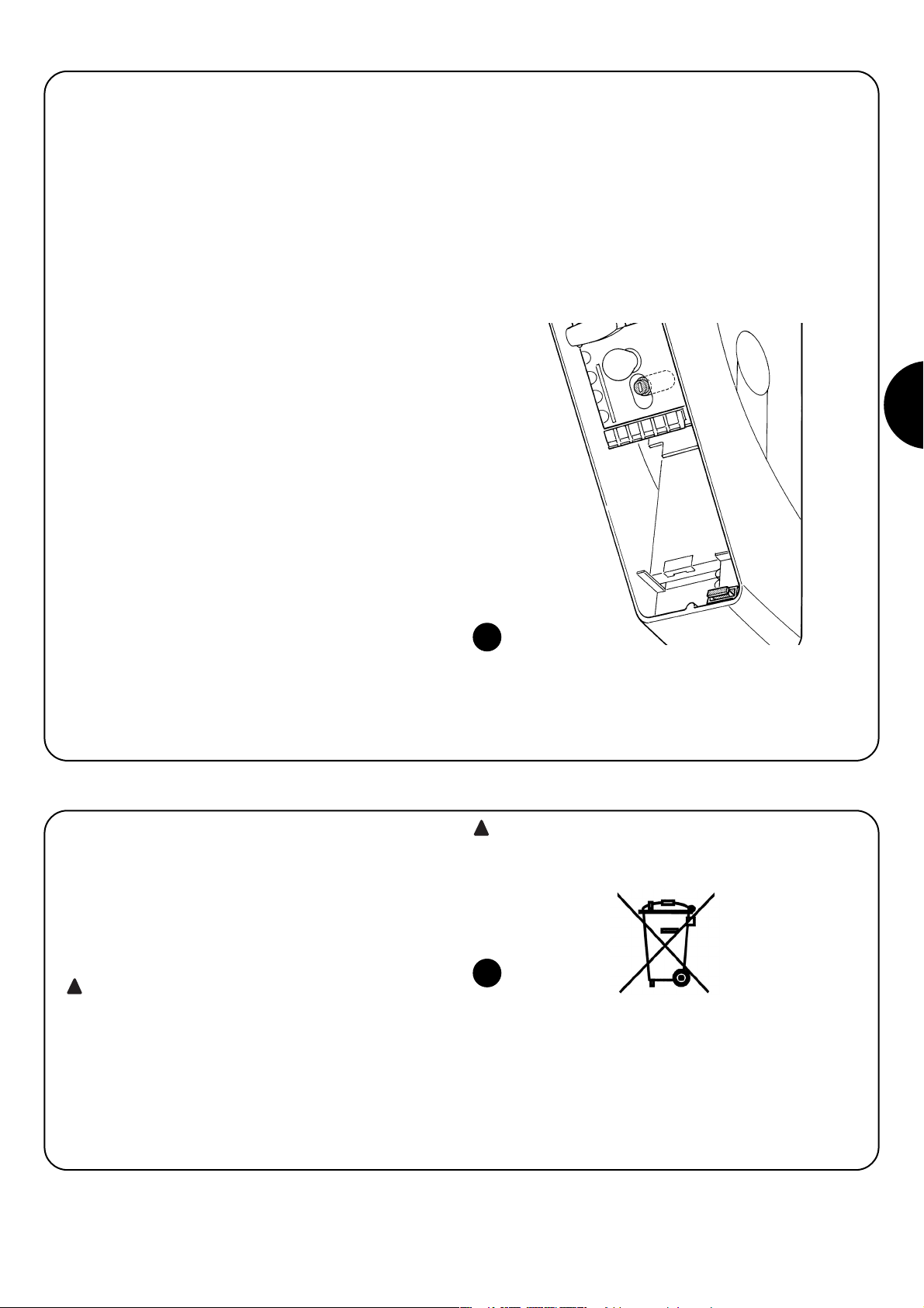
65
D
17) Was tun, wenn... (Leitfaden zum Lösen von Problemen)
Hier folgt eine kurze Anleitung zur Lösung der üblichsten Probleme,
die bei der Installation und Programmierung der Automatisierung
auftreten können.
•
Es erfolgt keine Bewegung und die BlueBUS-LED blinkt
nicht.
- Prüfen, ob Soon mit der 230V Netzspannung gespeist ist. Prüfen,
ob die Sicherungen F1 und F2 (Abb. 15) unterbrochen sind; in diesem Fall die Ursache des Defekts überprüfen, dann die Sicherungen mit anderen mit demselben Stromwert und denselben Merkmalen auswechseln.
•
Es erfolgt keine Bewegung und die Blinkleuchte blinkt
nicht.
- Prüfen, ob der Befehl effektiv empfangen wird. Falls der Befehl am
Eingang PP angelangt, muss die jeweilige LED “PP” aufleuchten,
wenn dagegen der Funksender benutzt wird, muss die BlueBUSLED zweimal schnell blinken.
• Es erfolgt keine Bewegung und die zusätzliche Beleuch-
tung blinkt mehrmals.
Zählen, wie oft die Beleuchtung blinkt und nach den Angaben in
Tabelle Nr. 7 überprüfen.
• ...während der Bewegung erfolgt eine kurze Umkehrung
- Die gewählte Kraft könnte für das Tor zu gering sein. Prüfen, ob
Hindernisse vorhanden sind und ggf. eine stärkere Kraft wählen.
- Prüfen, ob eine am Eingang Stopp angeschlossene Sicherheitsvorrichtung ausgelöst hat.
• …die Bewegung wird ausgeführt, aber die am Ausgang
FLASH angeschlossene Vorrichtung funktioniert nicht
- Prüfen, dass die an Ausgang FLASH angeschlossene Vorrichtung
die effektiv programmierte ist.
- Prüfen, ob Spannung an der Klemme der Vorrichtung vorhanden
ist, wenn diese gespeist sein müsste; falls ja, hängt das Problem
mit der Vorrichtung zusammen, die mit einer mit denselben Merkmalen ersetzt werden muss. Falls keine Spannung vorhanden ist,
ist der Ausgang elektrisch überlastet. Prüfen, dass das Kabel nicht
kurzgeschlossen ist.
•
…während der Speicherung der Maße blinken die LEDS
1 oder 8 schnell
- Bedeutet, dass das Extralaufmaß hoch (L1 blinkt schnell) oder
niedrig (L8 blinkt schnell) erreicht wurde.
- Falls L1 blinkt, eine Schließbewegung ausführen, bis L1 nicht mehr
schnell blinkt. Dann Soon von der Federtragwelle abmontieren,
das Tor in max. Position öffnen und Soon ab dieser Position wieder installieren.
- Falls L8 blinkt, eine Öffnungsbewegung ausführen, bis L8 nicht
mehr schnell blinkt. Dann Soon von der Federtragwelle abmontieren, das Tor in max. Position schließen und Soon ab dieser Position wieder installieren.
15
Wie die Installationsarbeiten muss auch die Abrüstung am Ende der
Lebensdauer dieses Produktes von technischem Fachpersonal
ausgeführt werden.
Dieses Produkt besteht aus verschiedenen Stoffen, von denen einige recycled werden können, andere müssen hingegen entsorgt werden. Informieren Sie sich über die Recycling- oder Entsorgungssysteme für dieses Produkt, die von den auf Ihrem Gebiet gültigen
Verordnungen vorgesehen sind.
Bestimmte Teile des Produktes können Schadstoffe
oder gefährliche Substanzen enthalten, die, falls in die
Umwelt gegeben, schädliche Wirkungen auf die Umwelt
und die Gesundheit der Menschen haben könnten.
Wie vom Symbol in Abb. 16 angegeben, darf dieses Produkt nicht in
den Hausmüll gegeben werden. Daher differenziert nach den Methoden entsorgen, die von den auf Ihrem Gebiet gültigen Verordnungen
vorgesehen sind, oder das Produkt dem Verkäufer beim Kauf eines
neuen, gleichwertigen Produktes zurückgeben
Die örtlichen Verordnungen sehen schwere Strafen im
Fall einer widerrechtlichen Entsorgung dieses Produktes
vor.
!
!
16
18) Entsorgung
Page 66

66
Soon
Índice pág.
Instrucciones para instalar y poner en
funcionamiento la automatización 67
1 Trabajar en condiciones seguras 67
1.1 Precauciones y advertencias de seguridad 67
2 Conocer las características del producto 67
2.1 Descripción del producto, uso adecuado y
características técnicas 67
3 Evaluar la factibilidad de la instalación 68
3.1 Control de los componentes del producto 68
3.2 Control de la idoneidad del ambiente 68
3.3 Control de los límites de empleo del producto 68
4 Instalar los diferentes componentes 68
4.1 Esquema típico de instalación 68
4.2 Instalación de los componentes mecánicos 69
4.3 Tendido de los cables eléctricos 70
4.4 Procedimiento manual de bloqueo y desbloqueo 70
5 Efectuar las conexiones eléctricas 70
5.1 Conexión de todos los dispositivos 70
5.2 Conexión de los dispositivos BlueBUS 72
5.2.1 Fotocélulas 72
5.2.2 Fotosensor FT210B 72
5.3 Conexión de los dispositivos a la entrada STOP 72
5.4 Conexión de la alimentación eléctrica 73
6 primer encendido de la instalación - controles 73
6.1 Test de funcionamiento 73
7 Memorización de los dispositivos y posiciones 73
7.1 Memorización de los dispositivos 73
7.2 Memorización de las posiciones 74
8 Efectuar el ensayo final de la instalación 75
8.1 Test para el ensayo final 75
8.2 Puesta en servicio 75
INTRODUCCIÓN
En este manual se explica cómo instalar, programar y utilizar
dispositivo para abrir y cerrar puertas seccionales Soon. Los
argumentos están subdivididos en tres partes diferentes:
La PRIMERA PARTE es una guía paso a paso que ilustra las
etapas necesarias para la instalación “física” del producto y
para ponerlo en funcionamiento.
La SEGUNDA PARTE describe cómo personalizar el funcionamiento de Soon mediante la programación de algunas funciones específicas y la elección de opcionales y regulaciones
especiales. También hay una sección dedicada al mantenimiento y al desguace del producto.
La Primera y la Segunda Parte del manual están destinadas
exclusivamente al Personal Técnico cualificado que instalará la automatización. Ninguna de estas informaciones puede ser considerada útil
para el Usuario final del producto
!
9 Instrucciones para personalizar el
funcionamiento de la automatización 76
9.1 Botones de programación 76
10 Programaciones 76
10.1 Funciones de primer nivel 76
10.2 Programaciones de primer nivel 77
10.3 Funciones de segundo nivel
(parámetros regulables) 77
10.4 Programaciones de segundo nivel 78
11 Aviso de mantenimiento 78
11.1 Control del número de maniobras efectuadas 79
11.2 Puesta a cero del contador de maniobras 79
12 Listado del historial de los desperfectos 79
13 Conexión de otros dispositivos 79
14 Otras informaciones: funciones especiales 80
14.1 Función “Abrir siempre” 80
14.2 Función “Mover igualmente” 80
15 Funcionamiento de la automatización mediante
transmisor y receptor “SM” 80
16 Control y diagnóstico automático de los
desperfectos de funcionamiento 80
17 Qué hacer si ...
(Guía para resolver los problemas) 81
18 Desguace 81
Page 67

67
E
Instrucciones para instalar y poner en funcionamiento la automatización
En esta PRIMERA PARTE se describen paso a paso todas las etapas de
instalación del producto (montaje mecánico, conexiones eléctricas,
ensayo) y su primera puesta en funcionamiento (configuraciones de funcionamiento).
Estas etapas están antecedidas por indicaciones muy importantes
sobre la seguridad, las características del producto y la factibilidad de la
instalación.
1.1) Precauciones y advertencias de seguridad
Las operaciones de instalación, programación y puesta en servicio del producto deben ser efectuadas únicamente por personal
técnicamente cualificado, respetando las leyes y normas vigentes
respectivas, y también las instrucciones contenidas en este manual.
Este manual está estructurado para guiar paso a paso el trabajo de
instalación, programación y puesta en servicio del motorreductor
Soon. Todas las operaciones que hay que efectuar, junto con las
instrucciones necesarias, están mencionadas en el orden exacto en
que deberán llevarse a cabo.
Por lo tanto, es importante leer todas las secciones del manual antes
de comenzar con la instalación. Se recomienda leer detenidamente
las Secciones que contienen informaciones fundamentales para la
SEGURIDAD como la Sección 1, la Sección 3 - CONTROLES A
EFECTUAR ANTES DE LA INSTALACIÓN Y LÍMITES DE EMPLEO
DEL PRODUCTO, y la Sección 8 - ENSAYO Y PUESTA EN SERVICIO DEL SISTEMA.
Considerando los peligros que pueden generarse durante la instalación y el uso diario del producto, es necesario que la instalación se
realice respetando plenamente la Directiva europea n° 98/37/CE
(Directiva de Máquinas que reglamenta la realización de una puerta
o de una cancela automática) y, en especial, las normas EN 12445,
EN 12453 y EN 12635.
La observancia de esta Directiva le permitirá trabajar con la máxima
seguridad, pudiendo emitir al final del trabajo la declaración de la
presunta conformidad y la seguridad de la instalación.
NOTA: Más informaciones y directrices para el análisis de los riesgos, útiles para la realización del “Expediente Técnico”, están
disponibles en la página web: www.niceforyou.com .
• Está prohibido utilizar el producto Soon de manera diferente de
aquella indicada en este manual. Un uso inadecuado podría averiar el producto y ser peligroso para las personas o bienes.
• Está prohibido modificar cualquier componente del producto sal-
vo que esté indicado expresamente en el manual. Las operaciones no autorizadas pueden provocar desperfectos de funcionamiento; Nice
®
no se asume ninguna responsabilidad por daños
provocados por productos modificados arbitrariamente.
• Antes de comenzar la instalación es necesario realizar el análisis
de los riesgos, que incluye la lista de los requisitos esenciales de
seguridad previstos en el anexo I de la Directiva de Máquinas, indicando las respectivas soluciones adoptadas. Recuerde que el
“análisis de los riesgos” es uno de los documentos que forman
parte del “Expediente Técnico” de la automatización.
• Antes de comenzar la instalación compruebe si es necesario
incorporar otros dispositivos y materiales que puedan servir para
completar la automatización con Soon, evaluando la situación de
empleo específica y los peligros presentes: por ejemplo, deben
tenerse en cuenta los peligros de choque, aplastamiento, corte,
arrastre y otros peligros en general.
• Conecte exclusivamente la Central de mando de Soon a una línea
de alimentación eléctrica dotada de puesta a tierra de seguridad.
• Durante la instalación, tenga cuidado de que las piezas de la automatización no sean sumergidas en el agua o en otras sustancias
líquidas, ni que dichas sustancias u objetos sólidos entren dentro
de la central o de los demás dispositivos abiertos. Si así fuera,
desconecte inmediatamente la alimentación eléctrica y contacte
con el Servicio de Asistencia Nice
®
.
¡Utilizar el Soon en estas situaciones puede ser peligroso!
• No coloque los componentes del Soon cerca de fuentes de calor
ni los exponga al fuego. Esto podría averiar los componentes del
sistema y provocar desperfectos de funcionamiento, incendios o
situaciones peligrosas.
• Durante la instalación, todas las operaciones que requieren el
acceso a las piezas internas cubiertas por la tapa de Soon (por ej.
los bornes) deben efectuarse con la alimentación eléctrica cortada. Si la conexión ya ha sido efectuada y el dispositivo de desconexión no está a la vista, es importante colocar un cartel que indique: "¡ATENCIÓN! MANTENIMIENTO EJECUTÁNDOSE”.
• Si durante la instalación se desconectaran los sistemas de protección eléctrica, tales como los interruptores automáticos o los
fusibles, antes de restablecerlos hay que localizar y eliminar la
avería.
• Al concluir la instalación, la automatización puede utilizarse sólo
después de haber efectuado la “puesta en servicio”, tal como
especificado en la Sección 8 - ENSAYO Y PUESTA EN SERVICIO
DEL SISTEMA.
• Si el Soon debe permanecer por mucho tiempo inactivo, se aconseja extraer la batería opcional y guardarla en un lugar seco. Dicha
medida de precaución evitará que la batería se deteriore y que de
ésta salgan sustancias peligrosas.
• Si hubiera algún desperfecto que no se pueda resolver por medio
de las informaciones contenidas en este manual, se aconseja contactar con el Servicio de Asistencia Nice
®
.
• El material de embalaje del producto Soon debe eliminarse respetando la normativa local en materia de eliminación de residuos.
• Se recomienda conservar con cuidado este manual para facilitar
las futuras operaciones de mantenimiento o reparaciones del producto.
!
!
1) Trabajar en condiciones seguras
2.1) Descripción del producto, uso adecuado y características técnicas
2) Conocer las características del producto
SOON es un actuador electromecánico para la automatización de
puertas seccionales de hasta 20m
2
. El eje hueco de salida permite
un acoplamiento fácil al eje portamuelles de la mayoría de las puertas seccionales en comercio.
La central SOA2, además de alimentar el motor con corriente continua, permite una regulación excelente del par y de la velocidad del
motorreductor, una medición exacta de las medidas, el arranque y el
cierre graduales, y la detección del obstáculo. Además la central
incorpora un indicador de mantenimiento que memoriza las maniobras que el motorreductor ejecuta durante toda su vida útil.
El dispositivo de desbloqueo, que se acciona desde el suelo, desactiva el motor del cuerpo del reductor.
Page 68

68
Antes de proceder con la instalación, controle que los componentes del producto estén íntegros, que el modelo corresponda con el pedido y que sea idóneo para el entorno en el cual debe ser instalado.
3) Evaluar la factibilidad de la instalación
3.1) Control de los componentes del producto (véase la fig. 1)
Controle que el embalaje esté íntegro;
desembale el producto y compruebe que se encuentren los siguientes elementos:
- 1 motorreductor Soon
- 1 estribo de fijación
- 4 semicasquillos de desbloqueo
- 2 llaves
- 1 tornillo M8x130
- 1 tuerca M8 de seguridad
- 1 arandela Ø8
- 1 reenvío
- 3 tornillos autorroscantes negros
- 1 manual de instrucciones
La automatización debe ser instalada únicamente por personal cualificado, respetando las instrucciones dadas en
este manual, las leyes y las normas vigentes.
!
4) Instalar los diferentes componentes
4.1) Esquema típico de instalación (véase la Fig. 3)
La Fig. 3 muestra la instalación completa de un motorreductor Soon. En el dibujo se muestran los componentes y los cables necesarios para
la conexión, todo ensamblado y colocado según un esquema típico y usual.
Leyenda de los componentes mecánicos indicados en la Fig. 3:
1 - Motorreductor Soon
2 - Fotocélula
3 - Selector de llave
4 - Columna para fotocélula
5 - Luz intermitente
6 - Transmisor
7 - Banda de seguridad principal
Leyenda de los cables eléctricos en la Fig. 3:
A - Línea eléctrica de alimentación
B - Luz intermitente con antena
C - Fotocélulas
D - Selector de llave
E - Banda de seguridad principal
1
3.3) Control de los límites de empleo del producto (véase la fig. 2)
Controle los límites de empleo del Soon y de los accesorios que se
deseen montar, evaluando que sus características cumplan con las
exigencias del entorno y los límites indicados a continuación:
• Controle que las dimensiones de la puerta seccional no supere
20m
2
.
• Controle que el eje de movimiento de la puerta seccional sea com-
patible con el eje de salida del Soon, utilizando las llaves entregadas.
• Controle que el estribo de fijación a la pared sea suficientemente
largo.
3.2) Control de la idoneidad del ambiente
• Controle que el entorno escogido para la instalación sea compati-
ble con las medidas totales del modelo Soon (Fig. 2).
• Controle que no haya obstáculos en la trayectoria de la puerta
seccional que puedan limitar el movimiento total de apertura y de
cierre de la puerta.
• Controle que en el entorno escogido para la instalación se puedan
realizar fácilmente y de manera segura las maniobras manuales.
• Controle que cada dispositivo que deba fijar quede colocado
sobre una superficie firme y protegida de golpes accidentales.
2
Page 69

69
E
4.2) Instalación de los componentes mecánicos
Después de haber concluido los trabajos de preparación para la instalación (por ejemplo la realización de las rozas para los tubos de los
cables eléctricos o la colocación de las canaletas externas, la fijación
en el hormigón de los tubos y otras preparaciones útiles) se podrá
proceder con el montaje y la instalación completa de todos los componentes mecánicos y eléctricos del Soon. Proceda siguiendo el
orden indicado a continuación.
Montaje del motorreductor Soon (véase la Fig. 4)
1. (Fig. 4-a) Introduzca el eje de salida del Soon en el eje de transmisión de la puerta seccional, acoplándolos utilizando la llave
entregada de serie.
Realice esta operación con la puerta CERRADA.
2. (Fig. 4-b) Fije el estribo al Soon con el tornillo, la tuerca y la arandela entregados de serie.
3. (Fig. 4-c) Fije el estribo a la pared con un taco (no suministrado)
adecuado para el tipo de pared.
4. (Fig. 4-d) Soon puede instalarse en posición horizontal por
medio de un reenvío (suministrado) específico que debe fijarse
con tres tornillos (suministrados) en la posición indicada, observando las salidas de los cables de desbloqueo.
4a 4b
4c 4d
3
Page 70

70
4.3) Tendido de los cables eléctricos (véase la Fig. 3 y la Tab. 1)
Concluida la instalación de los componentes mecánicos, proceda con el tendido de todos los cables eléctricos necesarios, tomando como referencia la Fig. 3 donde se muestra la colocación típica de dichos cables, y la Tabla 1 donde se analizan detalladamente sus características técnicas.
Los cables utilizados para las conexiones de los diferentes dispositivos deben ser adecuados para el tipo de instala-
ción que se desea efectuar: se aconseja un cable tipo H03VV-F para instalaciones en interiores o en un local cubierto.
CARACTERÍSTICAS DE LOS CABLES ELÉCTRICOS
(Las letras de los cables también están indicadas en la Fig. 3)
!
Notas: (*) Si el cable de alimentación mide más de 30 m, habrá que utilizar un cable de sección más grande (por ejemplo 3 x 2,5mm2) y es
necesaria una puesta a tierra de seguridad cerca de la automatización.
Conexión Tipo de cable Longitud máxima admitida
A: Línea eléctrica de alimentación 1 cavo (3 x 1,5 mm2) 30 m (*)
B: Luz intermitente 1 cavo (2 x 1 mm2) 20 m
C: Antena 1 cable blindado (tipo RG58) 20 m (se aconseja: menos de 5 m)
D: Fotocélula 1 cavo (2 x 0,5 mm2) 30 m
E: Selector de llave 1 cavo (4 x 0,5 mm22) 50 m
F: Conexión bandas sensibles montadas
1 cavo (2 x 0,5 mm
2
) 20 m
en elementos móviles
Tabla 1: listado de los cables
4.4) Procedimiento manual de desbloqueo y bloqueo
Tome como referencia este procedimiento cada vez
que en el texto del manual se indique que haya que “bloquear” o “desbloquear” manualmente el mecanismos del
SOON.
Notas:
Las maniobras de desbloqueo o de bloqueo del mecanismo deben
hacerse exclusivamente con el motorreductor completamente detenido.
• La operación manual debe realizarse cuando no haya corriente
eléctrica, cuando haya algún desperfecto en la instalación, o cuando esté indicado expresamente en el texto del manual.
• El desbloqueo manual permite que la puerta seccional se mueva
libremente
!
Para desbloquear - tire de la bola A
Para bloquear - tire de la bola B
A fin de garantizar la seguridad del instalador y evitar daños a los componentes de la automatización, antes de efectuar las conexiones eléctricas o activar el Radiorreceptor, asegúrese de que la Central de mando esté DESCONECTADA de la red eléctrica y de posibles baterías de compensación.
!
5) Efectuar las conexiones eléctricas
5.1) Conexión de todos los dispositivos
Todas las conexiones eléctricas deben efectuarse sin tensión en la
instalación.
1. Para desmontar la tapa de protección y acceder a la central
electrónica de control del SOON quite el tornillo del costado y
levante la tapa tirando de ella hacia arriba (Fig. 5).
2. Afloje el prensaestopas libre y pase los cables para la conexión
a los bornes de la central. Deje los cables 20÷30 cm más largos
de lo necesario. Véase la tabla 1 para el tipo de cable y la Fig. 6
para las conexiones.
3. Conecte los cables según el esquema de la Fig. 7. Para mayor
comodidad, los bornes son extraíbles.
4. Concluidas las conexiones, bloquee los cables apretando el
prensaestopas. La parte que excede del cable de la antena
debe atarse a los demás cables con otra abrazadera.
65
Page 71

71
E
7
FLASH esta salida es programable (véase la SEGUNDA PARTE del manual) para conectar uno de los siguientes dispositivos:
Luz intermitente Si está programada como “luz intermitente” en la salida “FLASH”, es posible conectar una luz
intermitente NICE “LUCY B” con una bombilla de 12V 21W tipo automóvil.
Durante la maniobra destella con una frecuencia de 0,5s encendida y 0,5s apagada.
Salida “indicador puerta abierta” Si está programada como “indicador puerta abierta” en la salida “FLASH”, es
posible conectar un indicador luminoso de 24V máx. 5W para la señalización de puerta abierta.
También puede programarse para otras funciones; véase la SEGUNDA PARTE del manual
Ventosa* Si está programada como “ventosa” en la salida “FLASH”, es posible conectar una ventosa de 24V máx. 10W
(versiones sólo con electroimán, sin dispositivos electrónicos).
Cuando la puerta está cerrada, la ventosa se activa bloqueando la puerta. Se desactiva durante la apertura o el cierre.
Electrobloqueo* Si está programada como “electrobloqueo” en la salida “FLASH”, es posible conectar un
electrobloqueo con cerradura de golpe de 24V máx. 10W (versiones sólo con electroimán, sin dispositivos electrónicos).
Durante la maniobra de apertura el electrobloqueo se activa y queda activo para dejar libre la puerta y efectuar el
movimiento. Durante el cierre controle que el electrobloqueo se reenganche mecánicamente.
Electrocerradura* Si está programada como “electrocerradura” en la salida “FLASH”, es posible conectar una
electrocerradura con cerradura de golpe de 24V máx. 10W (versiones sólo con electroimán, sin dispositivos electrónicos).
Durante la maniobra de apertura la electrocerradura se activa y queda activa durante poco tiempo para dejar libre la puerta
y efectuar el movimiento. Durante el cierre controle que la electrocerradura se reenganche mecánicamente.
BLUEBUS en este borne se pueden conectar los dispositivos compatibles; todos se conectan en paralelo con dos conductores
solos por los que transita tanto la alimentación eléctrica como las señales de comunicación. Para más informaciones
sobre BlueBUS véase el párrafo “5.2 - Conexión de los dispositivos BlueBUS”.
STOP entrada para los dispositivos que bloquean o detienen la maniobra que se está ejecutando; con soluciones oportunas en la
entrada es posible conectar contactos tipo “Normalmente Cerrado”, “Normalmente Abierto”, dispositivos de resistencia constante
u ópticos. Para más informaciones sobre STOP, consulte el párrafo “5.3 - Conexión de los dispositivos a la entrada stop”.
PP entrada para los dispositivos que controlan el movimiento en modalidad Paso a Paso; es posible conectar contactos
tipo “Normalmente Abierto”.
OPEN entrada para los dispositivos que accionan el movimiento de apertura sola; es posible conectar contactos tipo
“Normalmente Abierto”.
CLOSE entrada para los dispositivos que accionan el movimiento de cierre solo; es posible conectar contactos tipo
“Normalmente Abierto”.
ANTENA entrada de conexión de la antena para el radiorreceptor (la antena está incorporada en LUCY B).
* Pueden conectarse solamente los dispositivos que contienen el electroimán solo.
No utilice dispositivos diferentes de aquellos previstos
!
Page 72

72
5.2) Conexión de los dispositivos bluebus
BlueBUS es un sistema que permite efectuar las conexiones de los
dispositivos compatibles con dos conductores solos, por los cuales
pasan la alimentación eléctrica y las señales de comunicación.
Todos los dispositivos se conectan en paralelo en los mismos 2 conductores de BlueBUS y sin tener que respetar la polaridad; cada dispositivo es reconocido individualmente puesto que durante la instalación se le asigna una dirección unívoca. Al BlueBUS se le pueden
conectar, por ejemplo: fotocélulas, dispositivos de seguridad, botones de mando, indicadores luminosos de señalización, etc.
La central de control del SOON reconoce uno a uno todos los dispositivos conectados por medio de una etapa de aprendizaje adecuada, y es capaz de detectar con extrema seguridad todos los
desperfectos. Por dicho motivo, cada vez que se instala o desinstala un dispositivo conectado al BlueBUS, habrá que ejecutar el aprendizaje en la central, tal como descrito en el párrafo “7.1 - Memorización de los dispositivos”.
5.2.2) Fotosensor FT210B
El fotosensor FT210B agrupa en un único dispositivo un sistema de
limitación de la fuerza (tipo C según la norma EN12453) y un detector de presencia que detecta los obstáculos presentes en el eje óptico entre el transmisor TX y el receptor RX (tipo D según la norma
EN12453). En el fotosensor FT210B las señales del estado de la
banda sensible son enviadas mediante el rayo de la fotocélula integrando los 2 sistemas en un solo dispositivo. La parte transmisora
situada en la hoja móvil es alimentada con baterías eliminando así
los antiestéticos sistemas de conexión; unos circuitos especiales
reducen el consumo de la batería para garantizar una duración de
hasta 15 años (véanse los detalles de la evaluación en las instrucciones del producto). Un solo dispositivo FT210B, combinado con
una banda sensible (ejemplo TCB65), permite alcanzar el nivel de
seguridad de la "banda sensible principal" exigido por la norma
EN12453 para cualquier "tipo de utilización" y "tipo de activación".
El fotosensor FT210B, combinado con bandas sensibles "resistivas"
(8,2Kohm), es seguro para una avería única (categoría 3 según EN
954-1). Dispone de un circuito especial antichoque que evita interferencias con otros detectores aunque no estén sincronizados, y permite añadir otras fotocélulas; por ejemplo, si pasan vehículos veloces pesados donde normalmente se pone una segunda fotocélula a
1 m del suelo. Para más informaciones sobre los métodos de conexión y de direccionamiento, véase el manual de instrucciones de
FT210B.
5.3) Conexión de los dispositivos a la entrada stop
STOP es la entrada que provoca la parada inmediata de la maniobra, seguida de una breve inversión. A esta entrada se le pueden
conectar dispositivos con salida de contacto normalmente abierto
“NA”, normalmente cerrado “NC”, dispositivos con salida con resistencia constante 8,2KΩ, o bien dispositivos ópticos, por ejemplo
bandas sensibles.
Al igual que para el BlueBUS, la central reconoce el tipo de dispositivo conectado a la entrada STOP durante la etapa de aprendizaje
(véase el párrafo “7.1 - Memorización de los dispositivos”); sucesivamente, se provoca un STOP cuando se produce cualquier variación respecto del estado memorizado.
Con algunas soluciones oportunas es posible conectar varios dispositivos a la entrada STOP, incluso de diferentes tipos:
• Varios dispositivos NA pueden conectarse en paralelo entre sí sin
límites de cantidad.
5.2.1) Fotocélulas
El sistema “BlueBus” permite, mediante el direccionamiento con los
puentes de conexión, el reconocimiento de las fotocélulas por parte
de la central y asignar la función correcta de detección. La operación
de direccionamiento se realiza tanto en el TX como en el RX (colocando los puentes de conexión de la misma manera), comprobando
que no haya otros pares de fotocélulas con la misma dirección.
En una automatización para puertas correderas con el SOON es
posible instalar las fotocélulas según la representación de la Fig. 8.
Después de instalar o desinstalar las fotocélulas, en la central habrá
que ejecutar la etapa de aprendizaje tal como descrito en el párrafo
“7.1 - Memorización de los dispositivos”.
8
FOTO
Fotocélula h = 50
con accionamiento en el cierre
FOTO II
Fotocélula h = 100
con accionamiento en el cierre
FOTO 1
Fotocélula h = 50 con accionamiento tanto
en el cierre como en la apertura
FOTO 1 II
Fotocélula h = 100 con accionamiento tanto
en el cierre como en la apertura
FOTO 2
Fotocélula
con accionamiento en la apertura
FOTO 2 II
Fotocélula
con accionamiento en la apertura
FOTO 3
CONFIGURACIÓN NO ADMITIDA
Tabla 2: direcciones de las fotocélulas
Fotocélula
Puentes de conexión
Fotocélula
Puentes de conexión
Page 73
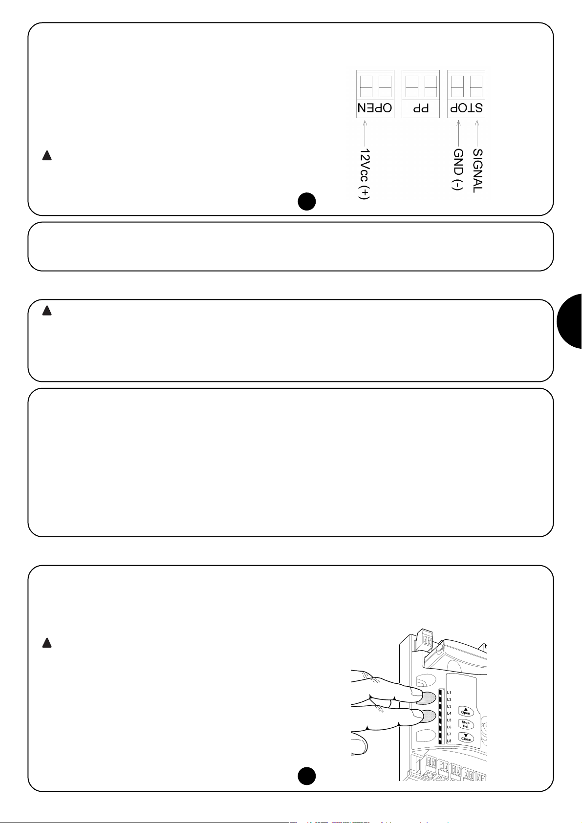
73
E
5.4) Conexión de la alimentación eléctrica
Para conectar la alimentación eléctrica al SOON basta con enchufar su clavija en un tomacorriente. De ser necesario, si la clavija del SOON
no corresponde al tomacorriente disponible, utilice un adaptador de esos que se encuentran generalmente en el comercio.
• Varios dispositivos NC pueden conectarse en serie entre sí sin límites de cantidad.
• Dos dispositivos con salida de resistencia constante 8,2KΩ pueden conectarse en paralelo; si hubiera más de 2 dispositivos,
entonces todos deben conectarse “en cascada” con una sola
resistencia de terminación de 8,2KΩ.
• La combinación NA y NC puede efectuarse colocando los 2 contactos en paralelo con la precaución de colocar, en serie al contacto NC, una resistencia de 8,2KΩ (esto permite también la combinación de 3 dispositivos: NA, NC y 8,2KΩ).
Si se utiliza la entrada STOP para conectar dispositivos
con funciones de seguridad, sólo los dispositivos con salida con resistencia constante 8,2 KΩ o dispositivos ópticos
OPTO SENSOR garantizan la categoría de seguridad 3
contra las averías, según la norma EN 954-1.
Para conectar un dispositivo óptico tipo OPTO SENSOR realice las
conexiones indicadas en la Fig. 9:
!
9
Las siguientes operaciones deben efectuarse en los circuitos eléctricos bajo tensión y las maniobras podrían ser
peligrosas. Por consiguiente, trabaje con mucho cuidado y nunca lo haga solo.
Concluido el montaje de los componentes y las conexiones eléctricas, antes de continuar es necesario realizar inmediatamente una comprobación sencilla del funcionamiento de la instalación. Efectúe las siguientes operaciones tildando los puntos a medida que vaya comprobando la conformidad de los resultados.
!
6) Primer encendido de la instalación - controles
7) Memorización de los dispositivos y posiciones
6.1) Test de funcionamiento
Ni bien se conecta la tensión al SOON se aconseja realizar algunos
controles sencillos:
K Controle que el led BLUEBUS destelle regularmente con una fre-
cuencia de un destello por segundo.
K Si estuvieran montadas las fotocélulas, controle que también des-
tellen los leds de las fotocélulas (tanto en TX como en RX); no es
importante el tipo de destello que depende de otros factores.
K Controle que el dispositivo conectado a la salida FLASH esté
apagado.
K Controle que la luz de cortesía esté apagada.
Si así no fuera, se aconseja apagar inmediatamente la alimentación
de la central y controlar más detenidamente las conexiones eléctricas.
7.1) Memorización de los dispositivos
Después de concluir la conexión de la alimentación, hay que hacer
que la central reconozca los dispositivos conectados a las entradas
BlueBUS y STOP. Antes de esta etapa los leds L1 y L2 destellan
indicando que hay que efectuar el aprendizaje de los dispositivos.
La fase de aprendizaje de los dispositivos debe ejecutarse aunque no haya ningún dispositivo conectado.
1. Pulse y mantenga pulsados los botones [▲] y [Set].
2. Suelte los botones cuando los leds L1 y L2 comiencen a deste-
llar muy rápidamente (después de unos 3s).
3. Espere algunos segundos a que la central concluya el aprendi-
zaje de los dispositivos.
Al concluir el aprendizaje, el led STOP debe quedar encendido y los
leds L1 y L2 se apagarán (podrían comenzar a destellar los leds L3
y L4).
La etapa de aprendizaje de los dispositivos conectados puede repetirse en cualquier momento, incluso después de la instalación (por
ejemplo si se añade un dispositivo).
!
10
Page 74

74
7.2) Memorización de las posiciones
Después del aprendizaje de los dispositivos es necesario que la central reconozca las posiciones de apertura y cierre de la puerta. Es posible programar hasta 6 posiciones, a saber:
Posición Significado
A1 Cota de apertura máxima deseada. La puerta se detiene cuando llega a esta posición.
RA1 Cota de inicio de la desaceleración durante la apertura. Cuando la puerta llega a esta posición el motor desacelera
funcionando a la velocidad mínima.
RINT Cota de desaceleración intermedia durante el cierre. Programando este punto, la puerta comienza a desacelerar unos 50
cm antes, de manera de pasar la posición RINT a la velocidad mínima. Superada la cota RINT el motor funciona a la
velocidad programada.
AP Cota de apertura parcial. Es la cota en que la puerta se detiene después de haber accionado un mando de apertura parcial.
RA0 Cota de inicio de la desaceleración durante el cierre. Cuando la puerta llega a esta posición el motor desacelera
funcionando a la velocidad mínima.
A0 Cota de cierre máximo. La puerta se detiene cuando llega a esta posición.
Cuando las cotas no han sido adquiridas, los leds L3 y L4 destellan.
A continuación se describe el procedimiento para memorizar las posiciones. Las cotas A1 y A0 deben programarse mientras que las demás
cotas pueden obviarse. En este último caso las cotas serán calculadas automáticamente por la central.
1. Pulse [Set] + [▼] durante 3 segundos para entrar en la memorización de las cotas.
El led L1 destella: programación cota A1
2. Con los botones [▲] o [▼] desplace la puerta hacia la posición de apertura máxima.
3. Pulse el botón [Set] durante 2 segundos para confirmar la cota A1. El led L1 queda encendido.
El led L2 destella: programación cota RA1
4. Si no se desea programar la cota de desaceleración de apertura, pulse 2 veces rápidamente el botón [Set] para pasar a la
programación siguiente, el led L2 queda apagado. En caso contrario, siga con la secuencia.
5. Con los botones [▲] o [▼] desplace la puerta hacia la posición de desaceleración apertura.
6. Pulse el botón [Set] durante 2 segundos para confirmar la cota RA1. El led L2 queda encendido.
El led L4 destella: programación cota RINT
7. Si no se desea programar la cota de desaceleración intermedia, pulse 2 veces rápidamente el botón [Set] para pasar a la
programación siguiente, el led L4 queda apagado. En caso contrario, siga con la secuencia.
8. Con los botones [▲] o [▼] desplace la puerta hacia la posición de desaceleración intermedia.
9. Pulse el botón [Set] durante 2 segundos para confirmar la cota RINT. El led L4 queda encendido.
El led L5 destella: programación cota RAP
10. Si no se desea programar la cota de apertura parcial, pulse 2 veces rápidamente el botón [Set] para pasar a la programación
siguiente, el led L5 queda apagado. En caso contrario, siga con la secuencia.
11. Con los botones [▲] o [▼] desplace la puerta hacia la posición de apertura parcial.
12. Pulse el botón [Set] durante 2 segundos para confirmar la cota RAP. El led L5 queda encendido.
El led L7 destella: programación cota RA0
13. Si no se desea programar la cota de desaceleración de cierre, pulse 2 veces rápidamente el botón [Set] para pasar a la
programación siguiente, el led L7 queda apagado. En caso contrario, siga con la secuencia.
14. Con los botones [▲] o [▼] desplace la puerta hacia la posición de desaceleración cierre.
15. Pulse el botón [Set] durante 2 segundos para confirmar la cota RA0. El led L7 queda encendido.
El led L8 destella: programación cota A0
16. Con los botones [▲] o [▼] desplace la puerta hacia la posición de cierre máximo.
17. Pulse el botón [Set] durante 2 segundos para confirmar la cota A0. El led L8 queda encendido.
18. Al soltar el botón [Set] se apagan todos los leds.
19. Accione un mando de apertura pulsando el botón [Open] para ejecutar una maniobra completa de apertura.
20. Accione un mando de cierre pulsando el botón [Close] para ejecutar una maniobra completa de cierre.
Durante dichas maniobras la central memoriza la fuerza necesaria
para los movimientos de apertura y cierre.
Es importante que estas primeras maniobras no sean interrumpidas, por ej. por un mando de STOP.
La etapa de aprendizaje de las posiciones puede ejecutarse en cualquier momento, incluso después de la instalación; es suficiente
repetirla a partir del punto 1. Por el contrario, si es necesario modificar una sola cota, repita la secuencia a partir del punto 1 y pase a
la programación de las cotas no interesadas, pulsando 2 veces rápidamente el botón [Set] para cada posición que hay que saltar.
11
Page 75

75
E
8) Efectuar el ensayo final de la instalación
8.1) Test para el ensayo final
Cada componente de la automatización, por ejemplo las
bandas sensibles, fotocélulas, parada de emergencia,
etc., exige un fase de ensayo específica; por dicha razón
se deberán seguir los diferentes procedimientos indicados en los manuales de instrucciones respectivos.
Para el ensayo del SOON ejecute la siguiente secuencia
de operaciones:
1. Controle que se respeten estrictamente las indicaciones del
capítulo 1 “ADVERTENCIAS”.
2. Desbloquee la puerta del motor tirando hacia abajo del tirador
de desbloqueo. Controle que sea posible abrir y cerrar manualmente la puerta con una fuerza que no supere 225N.
3. Bloquee la puerta al motor tirando manualmente del tirador de
bloqueo.
4. Utilizando el selector o el transmisor, efectúe los ensayos de cierre y apertura de la puerta y controle que el movimiento de la
puerta sea el previsto.
5. Conviene efectuar diferentes ensayos para comprobar el deslizamiento de la puerta y los posibles defectos de montaje o de
regulación, así como la presencia de puntos de fricción.
6. Controle uno por uno el funcionamiento correcto de todos los
dispositivos de seguridad montados en la instalación (fotocélulas, bandas sensibles, etc.). Cada vez que un dispositivo se
acciona, el led “BlueBUS” en la central destella 2 veces para
confirmar que la central reconoce el evento.
7. Para controlar el funcionamiento de las fotocélulas y especialmente para que no haya interferencias con otros dispositivos,
pase un cilindro de 5 cm de diámetro y 30 cm de longitud por el
eje óptico, primero cerca del TX y después cerca del RX y, por
último, por el centro entre los dos y controle que el dispositivo
siempre se accione pasando del estado activo al estado de alarma y viceversa; por último, compruebe que provoque en la central la acción prevista, por ejemplo: que en la maniobra de cierre
provoque la inversión de movimiento.
8. Si las situaciones peligrosas causadas por el movimiento de la
puerta se han prevenido limitando la fuerza de impacto, hay que
medir la fuerza de acuerdo con la prescripción de la norma EN
12445. Si la regulación de la “Velocidad” y el control de la “Fuerza del motor” se usan como una ayuda del sistema para reducir
la fuerza de impacto, pruebe y busque la regulación que ofrezca
los mejores resultados.
8.2) Puesta en servicio
La puesta en servicio puede llevarse a cabo sólo después
de haber efectuado correctamente todas las etapas de
ensayo del Soon y de los demás dispositivos montados. No
está admitida la puesta en servicio parcial o en situaciones “precarias”.
1. Realice y conserve durante al menos 10 años el expediente técnico de la automatización que deberá incluir como mínimo: dibujo de conjunto de la automatización, esquema de las conexiones
eléctricas, análisis de los riesgos y soluciones adoptadas, declaración de conformidad del fabricante de todos los dispositivos
utilizados (para el Soon utilice la Declaración de conformidad CE
adjunta); copia del manual de instrucciones de uso y del plan de
mantenimiento de la automatización.
2. Aplique sobre la puerta una placa con los siguientes datos: tipo
de automatización, nombre y dirección del fabricante (responsable de la “puesta en servicio”), número de matrícula, año de
fabricación y marcado “CE”.
3. Aplique de manera permanente y en proximidad de la puerta una
etiqueta o una placa que indique las operaciones para el desbloqueo y la maniobra manual.
4. Aplique de forma permanente sobre la puerta una etiqueta o una
placa con esta imagen (altura mínima 60 mm).
5. Prepare y entregue al dueño de la automatización la declaración
de conformidad correspondiente.
6. Prepare y entregue al dueño el “Manual de instrucciones y
advertencias para el uso de la automatización”.
7. Prepare y entregue al dueño el plan de mantenimiento de la
automatización (que debe incluir todas las prescripciones sobre
el mantenimiento de cada dispositivo).
8. Antes de poner en funcionamiento la automatización, informe
adecuadamente y por escrito al dueño (por ejemplo en el manual
de instrucciones y advertencias para el uso de la automatización) acerca de los peligros y los riesgos presentes.
Page 76

76
En esta SEGUNDA PARTE se describe cómo personalizar el funcionamiento de la automatización mediante regulaciones y opcionales que
se han de memorizar en la memoria de la Central. Una sección final está dedicada a la solución de los problemas, al mantenimiento y al desguace del producto.
9) Instrucciones para personalizar el funcionamiento de la automatización
En la central de control del SOON hay disponibles algunas funciones
programables; las funciones se regulan con los 3 botones situados
en la central: [▲] [Set] [▼] y se visualizan a través de los 8 leds:
L1…L8.
Las funciones programables disponibles en SOON están dispuestas
en 2 niveles:
Primer nivel: funciones regulables en modo ON-OFF (activo o
desactivado); en este caso, cada led L1….L8 indica una función; si
está encendido, la función está activa, si está apagado, la función
está desactivada; véase la Tab. 3.
Segundo nivel: parámetros regulables en una escala de valores
(valores de 1 a 8); en este caso cada led L1….L8 indica el valor
regulado entre los 8 valores posibles; véase la Tab. 4.
10) Programaciones
El botón “OPEN” permite accionar la apertura de la puerta, o bien desplazar hacia arriba el punto de programación.
El botón “STOP” permite detener la maniobra; al pulsarlo durante más de
5 segundos, permite entrar en programación.
El botón “CLOSE” permite accionar el cierre de la puerta o desplazar hacia
abajo el punto de programación.
9.1) Botones de programación
En la central de control del SOON hay 3 botones que pueden utilizarse para el accionamiento de la central durante los ensayos y para las programaciones:
12
OPEN
▲
STOP
SET
CLOSE
▼
Led Función Descripción
L1 Cierre automático Esta función permite un cierre automático de la puerta después del tiempo de pausa programado, el
Tiempo Pausa está configurado de fábrica en 30 segundos, pero puede modificarse en 10, 20, 40, 60, 80,
120, 160 y 200 segundos. Si la función está desactivada, el funcionamiento es “semiautomático”.
L2 Cerrar después de Esta función permite tener la puerta abierta solo durante el tiempo necesario para el tránsito, en efecto, la
Fotocélula activación de "Foto" provoca siempre un cierre automático con un tiempo de pausa de (independientemente
del valor programado) El comportamiento cambia según si se activa o no la función de "Cierre Automático".
Con "Cierre automático" desactivado: la puerta siempre alcanza la posición de apertura total (aunque
si la Fotocélula queda descubierta antes). Al quedar descubierta la fotocélula se provoca el cierre
automático con una pausa 5s.
Con “Cierre Automático” activo: la maniobra de apertura se detiene inmediatamente después de que
las fotocélulas quedan descubiertas y comenzará la maniobra de cierre automático con una pausa de 5s.
La función "Cerrar después de Fotocélula" siempre se deshabilita en las maniobras interrumpidas por un
mando de Stop. Si la función "Cerrar después de fotocélula" no está activa el tiempo de pausa será aquel
programado, o no se producirá el cierre automático si la función no está activa.
L3 Cerrar Siempre La función “Cerrar Siempre” se activa provocando un cierre cuando al volver la alimentación se detecta que
la puerta está abierta. Por motivos de seguridad, la maniobra es antecedida de 3s de destello previo.
Si la función está desactivada, al volver la alimentación la puerta quedará detenida.
L4 Stand-By Esta función permite reducir al mínimo los consumos. Si esta función está activa, después de 1 minuto del
final de la maniobra la central apaga la salida BlueBUS (y después los dispositivos) y todos los leds, salvo el
led BlueBUS que destellará más lentamente. Cuando la central recibe un mando, restablece el funcionamiento.
Si la función está desactivada, los consumos no disminuirán.
L5 Inversión larga Esta función permite seleccionar el tipo de inversión que la puerta debe ejecutar por la activación de STOP
o del limitador de fuerza. Si la función está desactivada, la inversión es breve (15 cm aprox.). Si la función
está activa, la inversión se produce hasta la cota de apertura o de cierre máximo.
L6 Destello previo Con la función de destello previo se añade una pausa de 3s entre el encendido de la luz intermitente y el
inicio de la maniobra para advertir anticipadamente sobre la situación de peligro. Si el destello previo está
desactivado, el encendido de la luz intermitente coincide con el comienzo de la maniobra.
L7 Sensibilidad Esta función permite aumentar notablemente la sensibilidad del motor para la detección de obstáculos. Si
se utiliza como ayuda para la medición de la fuerza de impacto, regule también los parámetros “Velocidad”
y “Fuerza motor” en el menú del segundo nivel.
L8 Compensación Esta función permite compensar el alargamiento de los cables metálicos de la puerta y depende del uso de
una banda sensible resistiva 8,2KΩ u óptica OSE.
Durante el funcionamiento normal del SOON, cuando no se está ejecutando ninguna maniobra, los leds L1….L8 están encendidos o apagados según el estado de la función que estos representan, por ejemplo L1 está encendido si la función “Cierre automático” está activa.
Tabla 3: lista de las funciones programables: primer nivel
10.1) Funciones de primer nivel
Page 77

77
E
Tiempo de
pausa
Función P.P.
Velocidad del
motor
Salida
FLASH
Fuerza del
motor en la
apertura
Fuerza del
motor en el
cierre
L1
L2
L3
L4
L5
L6
L7
L8
L1
L2
L3
L4
L5
L6
L7
L8
L1
L2
L3
L4
L5
L6
L7
L8
L1
L2
L3
L4
L5
L6
L7
L8
L1
L2
L3
L4
L5
L6
L7
L8
L1
L2
L3
L4
L5
L6
L7
L8
10 segundos
20 segundos
40 segundos
60 segundos
80 segundos
120 segundos
160 segundos
200 segundos
Abrir - stop - cerrar - stop
Abrir - stop - cerrar - abrir
Abrir - cerrar - abrir - cerrar
Comunitario
Comunitario 2 (más de 2” se detiene)
Paso a Paso 2 (menos de 2” provoca apertura parcial)
Hombre presente
Apertura modo “semiautomático”, cierre modo “hombre presente”
Velocidad 1 (30% - lenta)
Velocidad 2 (44%)
Velocidad 3 (58%)
Velocidad 4 (72%)
Velocidad 5 (86%)
Velocidad 6 (100% - rápida)
Abrir V4, cerrar V2
Abrir V6, cerrar V4
Indicador Puerta Abierta
Activa si la puerta está cerrada
Activa si la puerta está abierta
Luz intermitente
Electrobloqueo
Electrocerradura
Ventosa
Indicador de mantenimiento
Fuerza 1 (baja)
Fuerza 2
Fuerza 3
Fuerza 4
Fuerza 5
Fuerza 6
Fuerza 7
Fuerza 8 (alta)
Fuerza 1 (baja)
Fuerza 2
Fuerza 3
Fuerza 4
Fuerza 5
Fuerza 6
Fuerza 7
Fuerza 8 (alta)
10.3) Funciones de segundo nivel (parámetros regulables)
Tabla 4: lista de las funciones programables: segundo nivel
Led de entrada
Parámetro Led (nivel)
Valor Descripción
Regula el tiempo de pausa,
es decir el tiempo antes del
cierre automático. Es válido
sólo si el cierre automático
está activo.
Regula la secuencia de
mandos asociados a la
entrada PP o al 1° mando
radio.
Regula la secuencia de
mandos asociados a la
entrada PP o al 1° mando
radio.
Selecciona el dispositivo
conectado a la salida
FLASH.
Regula el sistema de
control de la fuerza del
motor para adecuarlo al
peso de la puerta durante
la maniobra de apertura.
Regula el sistema de
control de la fuerza del
motor para adecuarlo al
peso de la puerta durante
la maniobra de cierre.
Nota: “ ” representa la regulación de fábrica SEGUE
L1
L2
L3
L4
L5
L6
10.2) Programaciones de primer nivel
Todas las funciones de primer nivel están configuradas de fábrica en “OFF” pero pueden cambiarse en cualquier momento como descrito a
continuación. Tenga cuidado cuando efectúe la operación porque hay un tiempo máximo de 10s entre la presión de un botón y otro; en caso
contrario el procedimiento se concluye automáticamente, memorizando las modificaciones hechas hasta ese momento.
Espere 10s para salir de la programación por conclusión del tiempo máximo.
Nota: los puntos 3 y 4 pueden repetirse durante la misma etapa de programación para colocar en ON u OFF las demás funciones.
1. Pulse y mantenga pulsado el botón [Set] durante unos 3s
2. Suelte el botón [Set] cuando el led L1 comienza a destellar
3. Pulse los botones [▲] o [▼] para pasar del led intermitente al led que representa la función a modificar
4. Pulse el botón [Set] para cambiar el estado de la función (destello breve = OFF; destello prolongado = ON)
Page 78

78
El SOON permite avisar al usuario cuándo efectuar un control de mantenimiento de la automatización. El número de
maniobras que deben ejecutarse antes de la señalización
puede seleccionarse entre 8 niveles, mediante el parámetro regulable “Aviso de mantenimiento” (véase la Tab. 4).
El nivel 1 de regulación es “automático” y tiene en cuenta la dificultad de las maniobras, es decir el esfuerzo y la duración de la maniobra, mientas que las demás regulaciones están fijadas según la can-
tidad de las maniobras. La señal de aviso de mantenimiento es indicada por la luz intermitente o por el Indicador luminoso de mantenimiento
según la programación (véase la Tab. 4).
Según el número de maniobras efectuadas respecto del límite programado, la luz intermitente Flash y el indicador luminoso de mantenimiento dan las señales indicadas en la Tab. 5.
11) Aviso de mantenimiento
Aviso de
mantenimiento
Listado de
desperfectos
L1
L2
L3
L4
L5
L6
L7
L8
L1
L2
L3
L4
L5
L6
L7
L8
Automático (según el esfuerzo de las maniobras)
1.000
2.000
4.000
6.000
8.000
10.000
12.000
Resultado 1amaniobra (la más reciente)
Resultado 2amaniobra
Resultado 3amaniobra
Resultado 4amaniobra
Resultado 5amaniobra
Resultado 6amaniobra
Resultado 7amaniobra
Resultado 8
a
maniobra
Led de entrada
Parámetro Led (nivel)
Valor Descripción
Regula el número de
maniobras, superado el
cual, señala la necesidad
de mantenimiento de la
automatización (véase el
párrafo “13 Aviso de
Mantenimiento”).
Permite comprobar el tipo
de desperfecto que se
produjo en las 8 últimas
maniobras (véase el párrafo
“14 Historial desperfectos”).
Nota: “ ” representa la regulación de fábrica
Todos los parámetros pueden regularse a placer sin ninguna contraindicación; sólo las regulaciones de la “Fuerza del motor en la apertura”
y la “Fuerza del motor en el cierre” podrían requerir ciertas precauciones:
• Se desaconseja utilizar valores de fuerza elevados para compensar el hecho de que la puerta tiene puntos de fricción anormales; una fuer-
za excesiva puede perjudicar el funcionamiento del sistema de seguridad o averiar la hoja.
• Si el control de la "Fuerza motor" se usa como ayuda del sistema para reducir la fuerza de impacto, después de cada regulación, repita la
medición de la fuerza tal como previsto por la norma EN 12445.
• El desgaste y las condiciones atmosféricas influyen sobre el movimiento de la puerta; por dicho motivo es necesario controlar periódica-
mente la regulación de la fuerza.
L7
L8
10.4) Programaciones de segundo nivel
Los parámetros regulables están configurados de fábrica como se muestra en la Tab. 4 con: “ ” pero se pueden cambiar en cualquier momento, tal como descrito a continuación. Tenga cuidado cuando efectúe la operación porque hay un tiempo máximo de 10s entre la presión de un
botón y otro; en caso contrario el procedimiento se concluye automáticamente, memorizando las modificaciones hechas hasta ese momento.
Espere 10s para salir de la programación por conclusión del tiempo máximo.
Nota: los puntos de 3 a 7 pueden repetirse durante la misma etapa de programación para regular varios parámetros
1. Pulse y mantenga pulsado el botón [Set] durante unos 3s
2. Suelte el botón [Set] cuando el led L1 comienza a destellar
3. Pulse los botones [▲] o [▼] para pasar del led intermitente al “led de entrada” que representa el parámetro a modificar
4. Pulse y mantenga pulsado el botón [Set], mantenga pulsado el botón [Set] durante los pasos 5 y 6
5. Espere unos 3s, después se encenderá el led que representa el nivel actual del parámetro a modificar
6. Pulse los botones [▲] o [▼] para desplazar el led que representa el valor del parámetro.
7. Suelte el botón [Set]
Cantidad de maniobras Señal en Flash Señal en indicador de mantenimiento
Inferior al 80% del límite Normal (0,5s encendido, 0,5s apagado) Encendida durante 2s al comenzar la apertura
Entre el 81 y el 100% del límite Al comenzar la maniobra queda encendido durante 2s Destella durante toda la maniobra
después prosigue normalmente
Superior al 100% del límite Al comenzar y al final de la maniobra queda encendido Destella siempre.
durante 2s después prosigue normalmente
Tabla 5: aviso de mantenimiento con Flash e indicador luminoso mantenimiento
Page 79

79
E
11.1) Control del número de maniobras efectuadas
Con la función de “Aviso de mantenimiento” es posible controlar las maniobras efectuadas en porcentaje sobre el límite configurado. Para
dicho control, proceda como descrito a continuación.
1. Pulse y mantenga pulsado el botón [Set] durante unos 3s
2. Suelte el botón [Set] cuando el led L1 comienza a destellar
3. Pulse los botones [▲] o [▼] para desplazar el led intermitente al L7, es decir el “led de entrada” para el parámetro “Aviso de
mantenimiento”.
4. Pulse y mantenga pulsado el botón [Set], mantenga pulsado el botón [Set] durante los pasos 5, 6 y 7
5. Espere unos 3s, posteriormente se encenderá el led que representa el nivel actual del parámetro “Aviso de mantenimiento”.
6. Pulse y suelte de inmediato los botones [▲] y [▼].
7. El led correspondiente al nivel seleccionado destellará algunas veces. La cantidad de destellos identifica el porcentaje de maniobras
efectuadas (en múltiplos de 10%) respecto del límite configurado. Por ejemplo: configurando el aviso de mantenimiento en L7 es
decir 10000, el 10% corresponde a 1000 maniobras; si el led de visualización destella 4 veces significa que se ha alcanzado el
40% de las maniobras (es decir entre 4000 y 4999 maniobras). Si no se alcanzó el 10% de las maniobras, el led no destellará.
8. Suelte el botón [Set].
El SOON permite visualizar los desperfectos que se hayan producido en las últimas 8 maniobras, por ejemplo la interrupción de una maniobra por
la activación de una fotocélula o de una banda sensible. Para comprobar el listado de los desperfectos, proceda como indicado a continuación.
1. Pulse y mantenga pulsado el botón [Set] durante unos 3s
2. Suelte el botón [Set] cuando el led L1 comienza a destellar
3.
Pulse los botones [▲] o [▼] para desplazar el led intermitente al L8, es decir el “led de entrada” para el parámetro “Listado desperfectos”
4. Pulse y mantenga pulsado el botón [Set], mantenga pulsado el botón [Set] durante los pasos 5 y 6
5. Espere unos 3s, se encenderán los leds correspondientes a las maniobras que han tenido algún desperfecto. El led indica el resultado
de la maniobra más reciente, el led L8 indica el resultado de la octava maniobra. Si el led está encendido significa que durante la
maniobra se han producir desperfectos; si el led está apagado significa que la maniobra se ha concluido sin problemas.
6. Pulse los botones [▲] y [▼] para seleccionar la maniobra deseada: el led correspondiente destellará la misma cantidad de veces
que la luz intermitente después de un desperfecto.
7. Suelte el botón [Set].
11.2) Puesta a cero del contador de maniobras
Después de haber hecho el mantenimiento de la instalación, es necesario poner a cero el contador de las maniobras. Proceda como descrito.
1. Pulse y mantenga pulsado el botón [Set] durante unos 3s
2. Suelte el botón [Set] cuando el led L1 comienza a destellar
3. Pulse los botones [▲] o [▼] para desplazar el led intermitente al L7, es decir el “led de entrada” para el parámetro “Aviso de
mantenimiento”.
4. Pulse y mantenga pulsado el botón [Set], mantenga pulsado el botón [Set] durante los pasos 5 y 6
5. Espere unos 3s, posteriormente se encenderá el led que representa el nivel actual del parámetro “Aviso de mantenimiento”.
6. Pulse y mantenga pulsados durante unos 5 segundos como mínimo los botones [▲] y [▼], después suelte los 2 botones. El led
correspondiente al nivel seleccionado ejecutará una serie de destellos rápidos para señalar que el contador de las maniobras fue
puesto a cero.
14. Suelte el botón [Set].
Si hubiera que alimentar algún dispositivo exterior, por ejemplo un
lector de proximidad para tarjetas por transponder o bien la luz de
iluminación del selector de llave, es posible tomar la alimentación tal
como indicado en la figura 12. La tensión de alimentación es 24Vcc
-30% ÷ +50% con corriente máxima disponible de 100mA.
13) Conexión de otros dispositivos
12) Listado del historial de los desperfectos
12
Page 80

80
14) Otras informaciones: funciones especiales
14.1) Función “abrir siempre”
La función “Abrir siempre” es una característica de la central de control que permite accionar siempre una maniobra de apertura cuando el
mando de “Paso a Paso” dura más de 2 segundos; esto es útil por ejemplo para conectar al borne PP el contacto de un reloj programador
para mantener abierta la puerta durante una cierta franja horaria. Dicha característica es válida cualquiera sea la programación de la entrada de PP salvo la programación como “Comunitaria 2”, véase el parámetro “Función PP” en la Tab. 4.
15) Funcionamiento de la automatización mediante transmisor y receptor “SM”
La Central incorpora un conector dedicado a la instalación de un
Receptor con enganche tipo “SM" (Fig. 13) para accionar la automatización con un Transmisor (el receptor y el transmisor son accesorios opcionales). Las cuatro Salidas del Receptor permiten accionar en la Central los siguientes mandos:
Si no se utiliza la antena incorporada en LUCYB u otro tipo de antena exterior, enrosque el cable rígido entregado con el receptor en el
borne de la antena (Fig. 14).
14.2) Función “mover igualmente”
Si alguno de los dispositivos de seguridad no funcionara correctamente o estuviera fuera de uso, es posible igualmente accionar y mover la
puerta en modalidad “Hombre presente”. Para más detalles, véase el párrafo “Accionamiento con dispositivos de seguridad fuera de uso”
presente en el anexo “Instrucciones y advertencias destinadas al usuario del motorreductor SOON”.
Salida N°1 Mando “P.P.” (Paso a Paso)
Salida N°2 Mando "Apertura parcial"
Salida N°3 Mando “Abrir”
Salida N°4 Mando “Cerrar”
Tabla 6: mandos con transmisor SMXI, SMXIS
16) Control y diagnóstico automático de los desperfectos de funcionamiento
Durante el funcionamiento regular, la Central mantiene constantemente bajo control los procesos de la automatización y señala posibles desperfectos mediante secuencias predeterminadas de destellos de la luz intermitente, luz de cortesía y “Led BlueBUS” (los destellos de diagnósticos se refieren siempre a la última acción realizada por el Soon). Para saber la correspondencia entre el número de destellos y las causas, consulte la siguiente tabla:
Tabla 7: destellos de diagnóstico
13 14
n° dest. causa
1 Error sincronización BlueBUS
2 Activación de Foto o error del Fototest
3 Fuerza del motorreductor insuficiente o detectado un obstáculo durante la carrera
4 Activación de los dispositivos de Stop
5 Error en los parámetros de la memoria
6 Activación del limitador de las maniobras interno
7 Falta de corriente en los circuitos del motor
8 Sobrecorriente en los circuitos del motor
Page 81

81
E
17) Qué hacer si... (Guía para resolver los problemas)
Esta es una pequeña guía para resolver los problemas más comunes que se pueden presentar durante la instalación y la programación de la automatización.
•
…no se acciona ninguna maniobra y el led “BlueBUS” no
destella
- Controle que el Soon esté alimentado con la tensión de red de
230V. Controle que los fusibles F1 y F2 (Fig. 15) no estén quemados; si así fuera, controle la causa de la avería y sustitúyalos con
otros con el mismo valor de corriente y características.
•
…no se acciona ninguna maniobra y la luz intermitente
está apagada
- Controle que el mando sea recibido efectivamente. Si el mando llega a la entrada PP, el led “PP” debe encenderse; por el contrario,
si se utiliza el transmisor, el led “BlueBUS” debe emitir dos destellos rápidos.
• …
la maniobra no arranca y la luz de cortesía destella
algunas veces
Cuente la cantidad de destellos y controle según lo indicado en la
Tab. 7.
• …
durante la maniobra se produce una breve inversión
- La fuerza seleccionada podría ser muy baja para mover la puerta.
Controle que no haya obstáculos y, de ser necesario, seleccione
una fuerza mayor.
- Controle si se ha desconectado algún dispositivo de seguridad
conectado a la entrada de Stop.
• …
la maniobra se ejecuta pero el dispositivo conectado a
la salida FLASH no funciona
- Controle que el dispositivo conectado a la salida “FLASH” esté
programado efectivamente.
- Controle que cuando el dispositivo deba ser alimentado, haya tensión en el borne del dispositivo; si hubiera tensión, el problema es
el dispositivo que habrá que sustituir con uno con las mismas
características. Si no hay tensión significa que hay una sobrecorriente eléctrica en la salida. Controle que no haya un cortocircuito en el cable.
•
…durante la memorización de las cotas, el led L1 o el led
L8 destellan rápidamente
- Significa que se ha alcanzado la cota de sobrerrecorrido alto (L1
destella rápidamente) o bajo (L8 destella rápidamente).
- Si el led L1 destella, ejecute una maniobra de cierre hasta que L1
deje de destellar rápidamente. Posteriormente desinstale el Soon
del eje portamuelles, abra la puerta en la posición máxima y reinstale el Soon en esta posición.
- Si el led L8 destella, realice una maniobra de apertura hasta que el
led L8 deje de destellar rápidamente. Posteriormente desinstale el
Soon del eje portamuelles, cierre la puerta en la posición máxima
y reinstale el Soon en esta posición.
15
Al igual que para las operaciones de instalación, también al final de
la vida útil de este producto, las operaciones de desguace deben ser
efectuadas por Personal Técnico cualificado.
Este producto está formado de varios tipos de materiales: algunos
pueden reciclarse y otros deben eliminarse. Infórmese sobre los sistemas de reciclaje o eliminación previstos por las normas locales
vigentes para esta categoría de producto.
Algunas partes del producto pueden contener sustancias contaminantes o peligrosas; si se abandonarán en el
medio ambiente podrían ser perjudiciales para el ambiente y para la salud de las personas.
Como indicado por el símbolo de la Fig. 16, está prohibido arrojar
este producto en los residuos domésticos. Para la eliminación, realice la recogida selectiva, según los métodos previstos por las normas locales vigentes, o bien entregue el producto al vendedor cuando compre un nuevo producto equivalente.
Las normas locales pueden prever sanciones importan-
tes en el caso de eliminación abusiva de este producto.
!
!
16
18) Desguace
Page 82
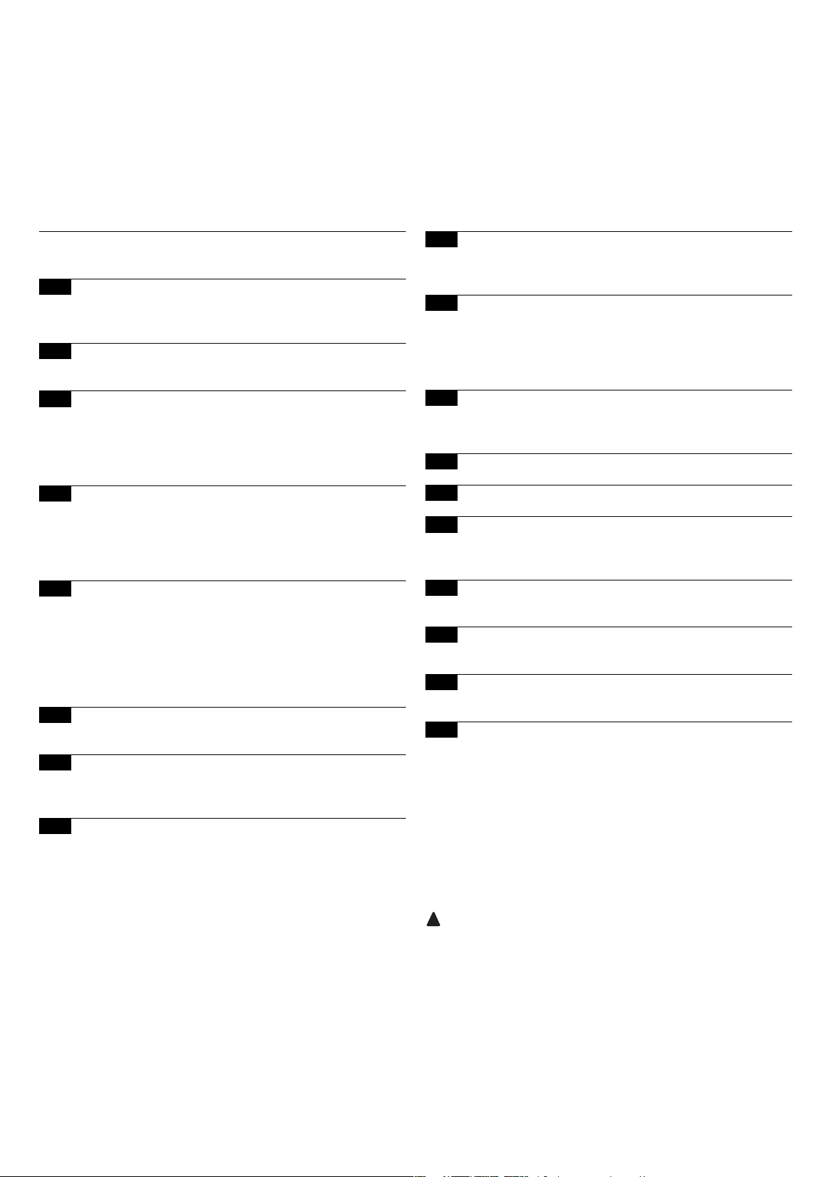
82
Soon
Spis treści pag.
Zalecenia dotyczące instalacji i uruchomienia
automatyki
83
1 Praca w bezpiecznych warunkach 83
1.1 Środki ostrożności i ostrzeżenia dotyczące
bezpieczeństwa 83
2 Zapoznanie się z charakterystyką produktu 83
2.1 Opis i przeznaczenie produktu, dane techniczne 83
3 Ocena możliwości wykonania instalacji 84
3.1 Sprawdzenie elementów produktu 84
3.2 Sprawdzenie otoczenia 84
3.3 Sprawdzenie ograniczeń eksploatacyjnych
produktu 84
4 Montaż poszczególnych elementów 84
4.1 Typowy schemat instalacji 84
4.2 Montaż elementów mechanicznych 85
4.3 Ułożenie przewodów elektrycznych 86
4.4 Ręczne wysprzęglanie i zasprzęglanie 86
5 Wykonanie podłączeń elektrycznych 86
5.1 Podłączenie wszystkich urządzeń 86
5.2 Podłączenie urządzeń BlueBUS 88
5.2.1 Fotokomórki 88
5.2.2 Fotoczujnik FT210B 88
5.3 Podłączenie urządzeń do wejścia STOP 88
5.4 Podłączenie zasilania 89
6 Pierwsze uruchomienie instalacji - testy 89
6.1 Testy prawidłowego działania 89
7 Rozpoznawanie urządzeń i pozycji 89
7.1 Rozpoznawanie dołączonych urządzeń 89
7.2 Rozpoznawanie pozycji 90
8 Końcowy odbiór techniczny instalacji 91
8.1 Testy podczas końcowego odbioru technicznego 91
8.2 Oddanie do eksploatacji 91
Wstęp
Niniejsza instrukcja przedstawia sposoby montażu,
programowania i użytkowania siłownika SOON do bram
segmentowych. Poszczególne tematy zostały podzielone na trzy
części:
Część Pierwsza to instrukcja, ilustrująca krok po kroku etapy
˝rzeczywistego˝ montażu produktu oraz jego uruchomienia
Część Druga opisuje możliwość personalizacji działania
siłownika SOON, poprzez zaprogramowanie funkcji specjalnych,
wybór opcji oraz specjalne regulacje. W części tej została
omówiona także konserwacja i późniejsza utylizacja produktu.
Część Pierwsza i Druga instrukcji są skierowane wyłącznie do
wykwalifikowanego Personelu Technicznego instalującego. Żadna z
zawartych tam informacji nie jest przeznaczona dla końcowego
Użytkownika produktu.
!
9 Zalecenia dotyczące personalizacji działania
automatyki 92
9.1 Przyciski programujące 92
10 Programowanie 92
10.1 Funkcje pierwszego poziomu 92
10.2 Programowanie funkcji pierwszego poziomu 93
10.3 Funkcje drugiego poziomu 93
10.4 Programowanie funkcji drugiego poziomu 94
11 Przypomnienie o konserwacji 94
11.1 Kontrola ilości przeprowadzonych manewrów 95
11.2 Zerowanie licznika manewrów 95
12 Historia anomalii 95
13 Podłączenie pozostałych urządzeń 95
14 Informacje dodatkowe: funkcje specjalne 96
14.1 Funkcja “Zawsze otwórz” 96
14.2 Funkcja “Wykonaj manewr mimo wszystko” 96
15 Działanie automatyki przy użyciu nadajnika i
radioodbiornika typu “SM” 96
16 Automatyczna kontrola i diagnostyka niepraw-
idłowego działania 96
17 Co robić gdy...
(Poradnik - rozwiązywanie problemów) 97
18 Utylizacja 97
Page 83

83
PL
Zalecenia dotyczące instalacji i uruchomienia automatyki
Część Pierwsza opisuje krok po kroku wszystkie etapy montażu automatyki
(montaż mechaniczny, podłączenia elektryczne, odbiór techniczny) oraz
pierwszego uruchomienia (ustawienia).
Etapy te są poprzedzone przez bardzo ważne informacje dotyczące
bezpieczeństwa, właściwości produktu i wykonalności instalacji.
Czynności związane z montażem, programowaniem i uruchomieniem
produktu mogą być wykonane wyłącznie przez wykwalifikowany personel
techniczny, zgodnie z obowiązującymi przepisami i normami oraz
zaleceniami zawartymi w niniejszej instrukcji. Instrukcja została
przygotowana tak, by poprowadzić instalatora krok po kroku podczas
montażu, programowania i uruchomienia siłownika SOON. Wszystkie
czynności, które należy wykonać oraz związane z nimi zalecenia zostały
przedstawione w kolejności wykonania poszczególnych etapów pracy.
Ważne jest zatem, aby przed przystąpieniem do montażu zapoznać się
z wszystkimi rozdziałami instrukcji. Zwracamy szczególną uwagę, na
przeczytanie z dużą uwagą rozdziałów, które zawierają podstawowe
informacje odnośnie BEZPIECZEŃSTWA, takie jak Rozdział 1, Rozdział
3 - SPRAWDZENIA PRZED MONTAŻEM I OGRANICZENIA
EKSPLOATACYJNE oraz Rozdział 8 - ODBIÓR TECHNICZNY I
ODDANIE DO EKSPLOATACJI. W związku z możliwością wystąpienia
zagrożeń - zarówno podczas montażu, jak i codziennego użytkowania
produktu - montaż musi zostać przeprowadzony według Dyrektywy
europejskiej nr 98/37/WE (Dyrektywa Maszynowa, określająca
wykonanie drzwi lub bram automatycznych), a w szczególności musi
odpowiadać normom EN 12445, EN 12453 i EN 12635.
Przestrzeganie postanowień Dyrektywy umożliwi Ci wykonanie pracy w
maksymalnie bezpiecznych warunkach, pozwalając jednocześnie na
wydanie na zakończenie oświadczenia o zgodności, a co za tym idzie,
o bezpieczeństwie instalacji.
Pamiętaj: Dodatkowe informacje i wytyczne dotyczące analizy ryzyka,
które mogłyby okazać się przydane podczas wykonania “Dokumentacji
Technicznej” są dostępne na stronie internetowej www.niceforyou.com.
• Zabrania się stosowania siłownika SOON w celach innych od
wskazanych w niniejszej instrukcji. Niewłaściwe użycie może
doprowadzić do uszkodzenia produktu i spowodować zagrożenie dla
osób i rzeczy.
• Zabrania się wprowadzania modyfikacji w jakimkolwiek elemencie
produktu, o ile nie są to zmiany opisane w niniejszej instrukcji.
Niedozwolone działania mogą doprowadzić do nieprawidłowego
funkcjonowania produktu. Firma Nice
®
nie bierze odpowiedzialności za
szkody spowodowane przez produkt zmodyfikowany na własną rękę.
• Przed rozpoczęciem montażu, musisz przeprowadzić analizę ryzyka,
zawierającą wykaz podstawowych wymogów bezpieczeństwa
przewidzianych w załączniku 1 do Dyrektywy Maszynowej, wskazując
zarazem wdrożone środki zapobiegawcze. Przypominamy, że “analiza
ryzyka” to jeden z dokumentów składających się na “Dokumentację
Techniczną” automatyki.
• Przed rozpoczęciem montażu powinieneś także sprawdzić czy
istnieje potrzeba montażu dodatkowych urządzeń i materiałów, które
mogłyby uzupełnić automatykę opartą na siłowniku SOON. Oceń
konkretną sytuację zastosowania i istniejące zagrożenia, weź pod
uwagę na przykład ryzyko uderzenia, przygniecenia, przecięcia,
wciągnięcia i inne podobne zagrożenia.
• Podłącz Centralę sterującą siłownika SOON do linii zasilania
wyposażonej w uziemienie zabezpieczające.
• Podczas montażu unikaj zetknięcia elementów automatyki z wodą
lub innymi płynami. Upewnij się również, że do wnętrza centrali i
innych otwartych urządzeń nie przedostaną się ani płyny, ani obiekty
stałe. Gdyby jednak do tego doszło, odłącz natychmiast zasilanie
elektryczne i skontaktuj się z Serwisem Nice
®
.
Użytkowanie siłownika SOON w takiej sytuacji może stanowić
źródło zagrożenia!
• Nie trzymaj elementów siłownika SOON blisko źródeł ciepła i
płomieni. Mogłoby to doprowadzić do zniszczenia elementów
instalacji, spowodować nieprawidłowe działanie, pożar lub inne
groźne sytuacje.
• Podczas montażu wszystkie czynności, które wymagają dostępu do
części wewnętrznych, znajdujących się pod pokrywą siłownika
SOON (np. do zacisków) muszą być wykonane przy odłączonym
zasilaniu. Jeśli podłączenie zasilania zostało już wykonane, a
urządzenie odcinające zasilanie znajduje się poza zasięgiem Twojego
wzroku, przywieś na nim karteczkę “UWAGA KONSERWACJA W
TOKU”.
• Jeśli podczas montażu zadziałają systemy ochrony elektrycznej takie
jak automatyczne wyłączniki lub bezpieczniki, zanim przywrócisz je
do normalnego stanu, znajdź i wyeliminuj uszkodzenie, które
wywołało ich interwencję.
• Po zakończeniu montażu, automatyka może być użytkowana tylko
po wcześniejszym przeprowadzeniu “oddania do eksploatacji”,
zgodnie ze wskazaniami zawartymi w Rozdziale 8 – ODBIÓR
TECHNICZNY I ODDANIE DO EKSPLOATACJI.
• W przypadku wystąpienia długich okresów przestoju w użytkowaniu
siłownika SOON, zaleca się wyjąć akumulator awaryjny i
przechowywać go w suchym miejscu. Dzięki temu unika się ryzyka
uszkodzenia akumulatora i wyciekania z niego substancji
szkodliwych.
• W przypadku gdy informacje zawarte w niniejszej instrukcji okażą się
niewystarczające do przywrócenia prawidłowego działania,
skontaktuj się z serwisem technicznym firmy Nice
®
.
• Opakowanie produktu Soon musi zostać zutylizowane zgodnie z
obowiązującymi przepisami lokalnymi.
• Zaleca się zachowanie niniejszej instrukcji dla ułatwienia przyszłej
konserwacji i ewentualnych interwencji na produkcie.
!
!
1.1) Środki ostrożności i ostrzeżenia dotyczące bezpieczeństwa
1) Praca w bezpiecznych warunkach
2.1) Opis i przeznaczenie produktu, dane techniczne
2) Zapoznanie się z charakterystyką produktu
SOON to elektromechaniczny siłownik do automatyzacji bram
segmentowych o powierzchni do 20m
2
.
Centrala SOA2, poza dostarczaniem do silnika prądu stałego, pozwala
na idealne wyregulowanie momentu obrotowego i prędkości siłownika,
dokładne odczytanie pozycji, stopniowe rozpoczęcie manewru
otwarcia i zamknięcia, wykrywanie przeszkód. Ponadto centrala jest
wyposażona w diodę “konserwacji”, która pozwala na rejestrowanie
manewrów wykonywanych przez siłownik podczas całego okresu
eksploatacji.
Ręczne wysprzęglenie odłącza silnik od przekładni, przy użyciu linek
dostępnych przez użytkownika.
Page 84
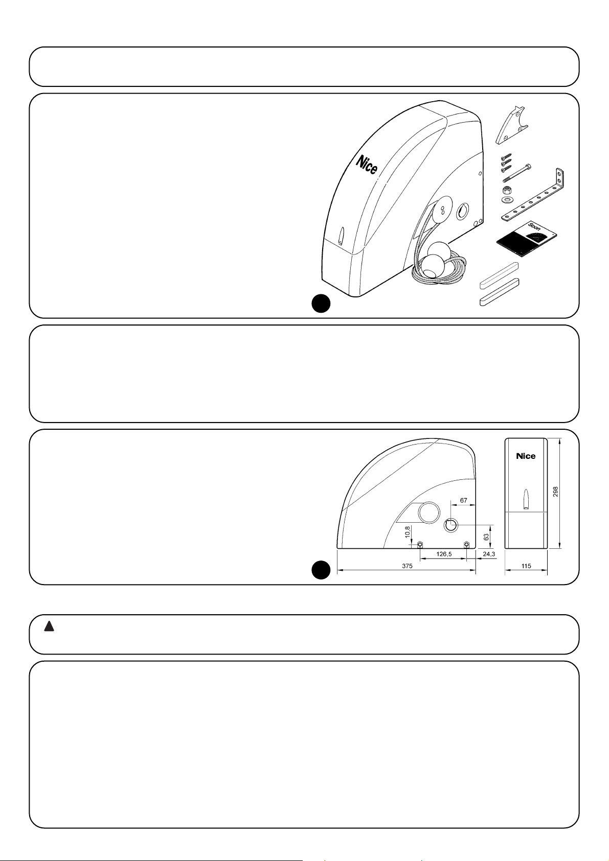
84
Przed przystąpieniem do montażu, upewnij się czy elementy produktu są nienaruszone, czy wybrano odpowiedni model oraz czy nadaje się on
do montażu w danym otoczeniu.
3) Ocena możliwości wykonania instalacji
3.1) sprawdzenie elementów produktu (Rys.1)
Sprawdź czy opakowanie jest nienaruszone;
odpakuj produkt i sprawdź czy zawiera on:
- siłownik SOON
- uchwyt mocujący
- 4 elementy gałek odblokowujących
- 2 wpusty
- 1 śruba M8x130
- 1 nakrętka samoblokująca M8
- 1 podkładka D8
- 1 prowadnica
- 3 śruby samogwintujące czarne
- 1 instrukcja obsługi
Czynności związane z montażem automatyki mogą być wykonane wyłącznie przez wykwalifikowany personel techniczny,
zgodnie z obowiązującymi przepisami i normami oraz zaleceniami zawartymi w niniejszej instrukcji.
!
4) Montaż poszczególnych elementów
4.1) Typowy schemat instalacji (Rys.3)
Na Rys. 3 przedstawiono kompletną instalację siłownika SOON. Rysunek przedstawia typowy schemat wykonania instalacji z zaznaczeniem
poszczególnych elementów oraz przewodów potrzebnych do ich montażu.
Legenda elementów mechanicznych przedstawionych na Rys. 3:
1 - Siłownik SOON
2 - Fotokomórka
3 - Przełącznik na klucz
4 - Słupek na fotokomórkę
5 - Lampa ostrzegawcza
6 - Nadajnik
7 - Główna listwa krawędziowa
Legenda przewodów elektrycznych przedstawionych na Rys. 3:
A - Linia zasilania
B - Lampa ostrzegawcza z anteną
C - Fotokomórki
D - Przełącznik na klucz
E - Główna listwa krawędziowa
1
3.3) Sprawdzenie ograniczeń eksploatacyjnych produktu (Rys.2)
Sprawdź ograniczenia eksploatacyjne siłownika SOON oraz
pozostałych akcesoriów, które mają zostać zamontowane. Oceń czy
właściwości produktów odpowiadają wymaganiom otoczenia i
wskazanym poniżej ograniczeniom:
• Upewnij się czy wielkość bramy segmentowej nie przekracza 20 m.
• Przy użyciu wpustów znajdujących się na wyposażeniu, sprawdź czy
wał napędowy bramy segmentowej jest kompatybilny z otworem
wyjściowym siłownika SOON.
• Upewnij się czy uchwyt mocujący do ściany jest wystarczająco długi.
3.2) Sprawdzenie otoczenia
• Upewnij się czy otoczenie, w którym ma zostać zamontowany
siłownik odpowiada pełnym wymiarom siłownika SOON (Rys. 2).
• Upewnij się czy na torze ruchu bramy segmentowej nie występują
przeszkody, które mogłyby ograniczyć wykonanie pełnego manewru
otwarcia i zamknięcia.
• Upewnij się czy w miejscu, w którym ma zostać wykonany montaż
istnieje możliwość przeprowadzenia manewrów ręcznych w sposób
łatwy i bezpieczny.
• Upewnij się czy do montażu każdego urządzenia przewidziane jest
miejsce o solidnej powierzchni, w którym nie występuje ryzyko
przypadkowych uderzeń.
2
Page 85
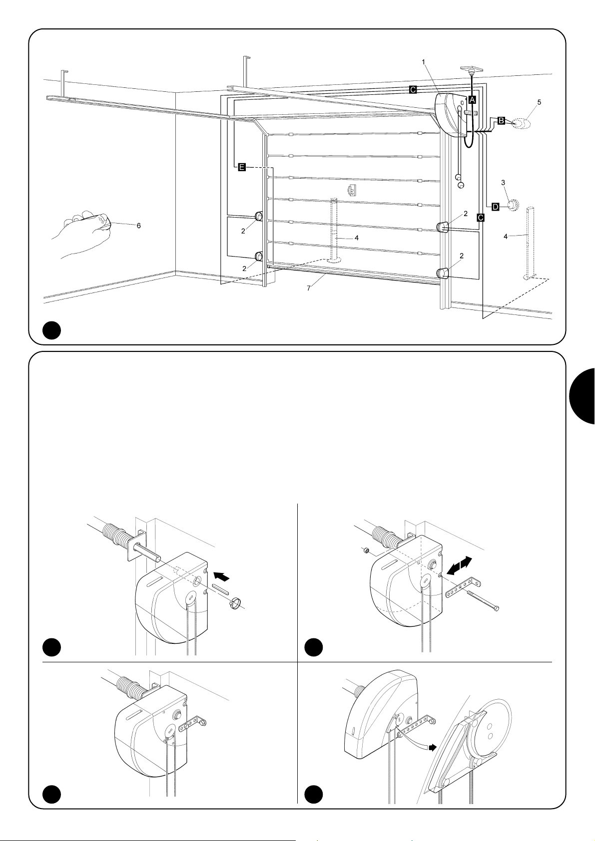
85
PL
4.2) Montaż elementów mechanicznych
Po zakończeniu prac przygotowawczych (np. wykonanie bruzd pod
rury z przewodami elektrycznymi i ułożenie zewnętrznych koryt
kablowych, ewentualne zamocowanie wspomnianych wyżej rur w
betonie i inne niezbędne prace wstępne) możesz przystąpić do
montażu i wykonania kompletnej instalacji wszystkich elementów
mechanicznych i elektrycznych siłownika SOON. Pamiętaj, aby
zachować wskazaną poniżej kolejność.
Montaż siłownika SOON (Rys. 4)
1. (Rys. 4-a) Wsuń siłownik SOON na wał napędowy bramy
segmentowej, łącząc je przy użyciu wpustu, który znajduje się na
wyposażeniu.
Czynność ta musi być wykonana przy ZAMKNIĘTEJ bramie.
2. (Rys. 4-b) Przy użyciu śruby, nakrętki i podkładki, które znajdują się
na wyposażeniu, zamontuj do siłownika SOON uchwyt mocujący.
3. (Rys. 4-c) Przy użyciu kołka rozporowego (brak w wyposażeniu)
przymocuj uchwyt do ściany. Wybierz kołek odpowiedni do typu
ściany.
4. (Rys. 4-d) Istnieje możliwość montażu siłownika SOON w pozycji
poziomej przy wykorzystaniu małej prowadnicy, który znajduje się
na wyposażeniu. Przy użyciu trzech śrub (na wyposażeniu),
przymocuj prowadnicę w pozycji przedstawionej na rysunku.
Zwróć uwagę na wyjście linek wysprzęglających
4a 4b
4c 4d
3
Page 86

86
4.3) Ułożenie przewodów elektrycznych (Rys. 3 i Tabela 1)
Po zakończeniu montażu poszczególnych elementów mechanicznych, możesz przystąpić do ułożenia przewodów elektrycznych. Postępuj według
Rys. 3, który pokazuje typowe ułożenie tych przewodów oraz Tabeli 1, zawierającej ich dane techniczne.
Przewody stosowane do podłączenia poszczególnych urządzeń muszą być odpowiednie do typu instalacji, jaką pragniesz
wykonać. W przypadku montażu w miejscu zadaszonym lub w pomieszczeniach zaleca się przewód typu H03VV-F.
WŁAŚCIWOŚĆI PRZEWODÓW ELEKTRYCZNYCH
(Litery przypisane przewodom odpowiadają oznaczeniom z Rys.3)
!
Pamiętaj: (*) Jeśli długość przewodu zasilania przekracza 30 cm, musisz użyć przewodu o większym przekroju (np. 3 x 2,5 mm2). Potrzebne
jest wówczas także uziemienie zabezpieczające w pobliżu automatyki.
Podłączenie Rodzaj przewodu Maksymalna dozwolona długość
A: Linia zasilania przewód (3 x 1,5 mm2), szt.1 30 m (*)
B: Lampa ostrzegawcza przewód (2 x 1 mm
2
), szt.1 20 m
C: Antena przewód ekranowany (typ RG58), szt.1 20 m (zalecana: mniej niż 5 m)
D: Fotokomórka przewód (2 x 0,5 mm
2
), szt.1 30 m
E: Przełącznik na klucz przewód (4 x 0,5 mm
2
), szt.1 50 m
F: Podłączenie zabezpieczających listew
przewód (2 x 0,5 mm
2
), szt.1 20 m
krawędziowych
Tabela 1: Wykaz przewodów
4.4) Ręczne wysprzęglanie i zasprzęglanie
Przedstawiona poniżej procedura obowiązuje
każdorazowo, gdy w tekście instrukcji jest mowa o ręcznym
“zasprzęglaniu” lub “wysprzęglaniu” mechanizmu siłownika
SOON.
Pamiętaj:
Manewr wysprzęglenia lub zasprzęglenia mechanizmu może być
wykonywany tylko przy całkowicie nieruchomym siłowniku.
• Ręczny manewr jest wykonywany w przypadku braku prądu,
wystąpienia anomalii w instalacji lub jeśli wyraźnie zaleca to instrukcja.
• Ręczne wysprzęglenie pozwala na swobodny ruch bramy
segmentowej.
!
W celu wysprzęglenia - pociągnij za kulkę A
W celu zasprzęglenia - pociągnij za kulkę B
Aby zapewnić bezpieczeństwo instalatora i uniknąć uszkodzenia elementów automatyki, przed wykonaniem podłączeń
elektrycznych lub włączeniem Nadajnika radiowego upewnij się czy Centrala sterująca jest ODŁĄCZONA od zasilania i od
ewentualnych akumulatorów buforowych.
!
5) Wykonanie podłączeń elektrycznych
5.1) Podłączenie wszystkich urządzeń
Wszystkie podłączenia elektryczne muszą być wykonywane na
odłączonym napięciu.
1. Aby zdjąć pokrywę zabezpieczającą i uzyskać dostęp do centrali
sterującej SOON, wykręć śrubę i podnieść pokrywkę odchylając ją
do góry (Rys.5).
2. Poluzuj wolną opaskę zaciskową i wsuń w nią przewody do
podłączenia do zacisków centrali. Zostaw przewody dłuższe o 2030 cm niż potrzeba. Typ przewodów znajdziesz w Tabeli 1,
natomiast podłączenia na Rys. 6.
3. Podłącz przewody według schematu przedstawionego na Rys. 7.
Istnieje możliwość wyjęcia zacisków, co usprawnia wykonanie
podłączeń.
4. Po wykonaniu podłączeń zablokuj przewody, zaciągając opaskę
zaciskową. Nadmiar przewodu anteny przymocuj do pozostałych
przewodów przy użyciu innej opaski.
65
Page 87
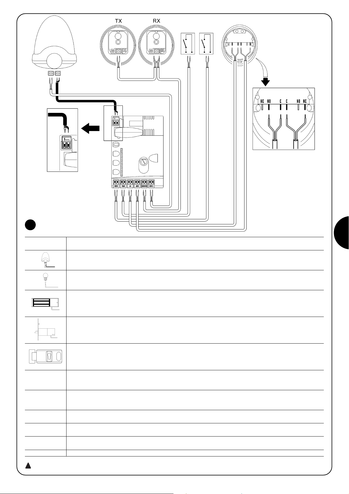
87
PL
7
FLASH istnieje możliwość zaprogramowania tego wyjścia (patrz CZĘŚĆ DRUGA instrukcji) tak, aby podłączyć jedno lub więcej
spośród następujących urządzeń:
Lampa ostrzegawcza Jeśli na wyjściu “FLASH” jest zaprogramowana “lampa ostrzegawcza” istnieje możliwość
podłączenia lampy ostrzegawczej NICE “LUCY B” z żarówką o mocy 12V/21W, typu samochodowego.
W czasie manewru lampa miga - 0.5 sekundy pali się i 0.5 sekundy jest zgaszona.
Wyjście “lampka sygnalizująca otwartą bramę” Jeśli na wyjściu “FLASH” jest zaprogramowana “lampka sygnalizująca
otwartą bramę” istnieje możliwość podłączenia lampki o napięciu 24V max 5W w celu sygnalizacji otwartej bramy.
Na tym wyjściu można zaprogramować także inne funkcje. Więcej informacji w CZĘŚCI DRUGIEJ instrukcji.
Blokada elektromagnetyczna* Jeśli na wyjściu “FLASH” jest zaprogramowana “blokada elektromagnetyczna” istnieje
możliwość podłączenia blokady elektromagnetycznej o napięciu 24V max 10W (wersja z samym elektromagnesem, bez
elektroniki sterującej). Kiedy brama jest zamknięta blokada elektromagnetyczna jest aktywna, blokując bramę. W czasie
manewru otwarcia lub zamknięcia blokada elektromagnetyczna nie jest aktywna.
Blokada elektryczna* Jeśli na wyjściu “FLASH” jest zaprogramowana “blokada elektryczna” istnieje możliwość podłączenia
blokady elektrycznej z zatrzaskiem, o napięciu 24V max 10W (wersja z samym elektromagnesem, bez elektroniki sterującej).
Blokada elektryczna jest aktywowana podczas manewru otwarcia, co pozwala na odblokowanie bramy i wykonanie
manewru. Upewnij się czy podczas manewru zamknięcia blokada elektryczna ponownie załącza się mechanicznie.
Zamek elektryczny* Jeśli na wyjściu “FLASH” jest zaprogramowany “zamek elektryczny” istnieje możliwość podłączenia
zamka elektrycznego z zatrzaskiem, o napięciu 24V max 10W (wersja z samym elektromagnesem, bez elektroniki sterującej).
Zamek elektryczny jest aktywowany na krótko podczas manewru otwarcia w celu zwolnienia bramy i wykonania manewru.
Upewnij się czy podczas manewru zamknięcia zamek elektryczny ponownie załącza się mechanicznie.
BLUEBUS do tego zacisku można podłączyć urządzenia kompatybilne. Wszystkie urządzenia są podłączone równolegle i tylko na
dwóch przewodach, przez które zarówno przechodzi zasilanie elektryczne jak i odbywa się transmisja danych. Więcej
informacji o BlueBUS znajdziesz się w punkcie “5.2 – Podłączenie urządzeń BlueBUS”.
STOP wejście dla urządzeń, które blokują lub zatrzymują manewr w toku. Przy użyciu odpowiednich sposobów można podłączyć
styki typu “Normalnie Zamknięty”, “Normalnie Otwarty”, urządzenia o stałej oporności lub typu optycznego. Więcej informacji
o wejściu STOP znajdziesz się w punkcie “5.3 – Podłączenie urządzeń do wejścia STOP”
KROK PO KROKU
wejście dla urządzeń, które sterują ruchem w trybie Krok po kroku. Istnieje możliwość podłączenia styków typu “Normalnie
Otwarty”.
OPEN wejście dla urządzeń, które sterują ruchem tylko podczas manewru otwarcia. Istnieje możliwość podłączenia styków typu
“Normalnie Otwarty”.
CLOSE wejście dla urządzeń, które sterują ruchem tylko podczas manewru zamknięcia. Istnieje możliwość podłączenia styków typu
“Normalnie Otwarty”.
ANTENA wejście podłączenia anteny odbiornika radiowego (antena jest wbudowana w LUCY B)
* Można podłączyć urządzenia posiadające wyłącznie elektromagnes.
Zakaz stosowania urządzeń innych od przewidzianych
!
Page 88
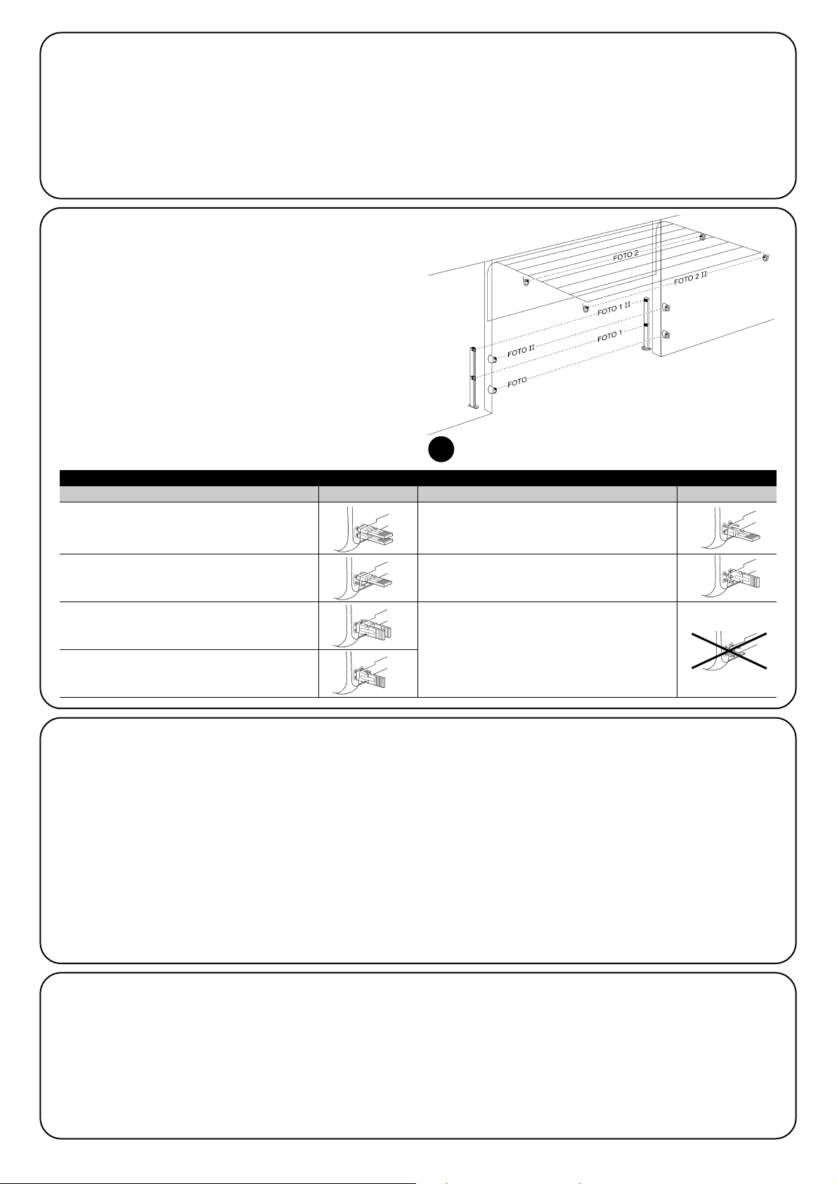
88
5.2) Podłączenie urządzeń bluebus
BlueBUS to technologia, która umożliwia podłączenie urządzeń
kompatybilnych przy użyciu jedynie dwóch przewodów, przez które
zarówno przechodzi zasilanie elektryczne jak i odbywa się transmisja
danych. Wszystkie urządzenia są podłączane równolegle, na tych
samych przewodach BlueBUS i bez konieczności zwracania uwagi na
biegunowość. Każde urządzenie jest rozpoznawane oddzielnie,
ponieważ podczas montażu jest mu przypisywany jednoznaczny adres.
Do BlueBUS można podłączyć na przykład fotokomórki, urządzenia
zabezpieczające, przyciski sterujące, lampki sygnalizacyjne, itd.
Wszystkie podłączone urządzenia są rozpoznawane automatycznie
przez centralę sterującą SOON podczas specjalnej procedury uczenia
się. Centrala jest w stanie wykryć z niezwykłą dokładnością wszelkie
anomalie. W związku z powyższym, za każdym razem, gdy dodajesz
lub usuwasz urządzenie podłączone do wyjścia BlueBUS, musisz
przeprowadzić w centrali procedurę uczenia, zgodnie z opisem
wskazanym w punkcie “7.1 – Rozpoznawanie dołączonych urządzeń”.
5.2.2) Fotoczujnik FT210B
Fotoczujnik FT210B stanowi połączenie w jednym urządzeniu systemu
ograniczenia siły (typ C, według normy EN12453) oraz wykrywacza
przeszkód występujących na osi optycznej pomiędzy nadajnikiem TX a
odbiornikiem RX (typ D, według normy EN12453). W fotoczujniku
FT210B sygnały statusu zabezpieczającej listwy krawędziowej są
przesyłane za pośrednictwem promienia fotokomórki, łącząc 2 systemy
w jednym urządzeniu. Część nadawcza znajdująca się na ruchomym
skrzydle jest zasilana baterią, co eliminuje potrzebę wykonywania
nieestetycznych systemów łączenia. Zużycie baterii jest zmniejszane
dzięki specjalnemu rozwiązaniu projektowemu, które przedłuża jej
trwałość do 15 lat (więcej na temat szczegółów oszacowania trwałości
znajdziesz w instrukcji produktu). Urządzenie FT210B, w połączeniu z
zabezpieczającą listwą krawędziową (np. TCB65), pozwala na
osiągnięcie poziomu bezpieczeństwa “głównej krawędzi zamykającej”
wymaganego przez normę EN12453 dla każdego “typu użycia” i “typu
aktywacji”. Fotoczujnik FT210B w połączeniu z zabezpieczającymi
listwami krawędziowymi “opornościowymi” (8,2KΩ), jest odporny na
pojedyncze uszkodzenie (kategoria 3, według EN 954-1). Jest
wyposażony w specjalny system anty-zakłóceniowy, który pozwala na
uniknięcie zakłóceń z innymi urządzeniami wykrywającymi, nawet jeśli
nie zostanie wcześniej przeprowadzona synchronizacja, i pozwala na
dodanie innych fotokomórek, np. gdy masz do czynienia z przejazdem
ciężkich pojazdów, kiedy to zazwyczaj należy zamontować dodatkową
fotokomórkę na wysokości 1 m od podłoża.
Więcej informacji dotyczących trybu podłączenia i adresowania
znajdziesz w instrukcji FT210B.
5.3) Podłączenie Urządzeń Do Wejścia STOP
STOP jest wejściem, które powoduje natychmiastowe zatrzymanie
manewru i krótki ruch w przeciwnym kierunku. Do tego wejścia mogą
być podłączone urządzenia z wyjściem ze stykiem normalnie otwartym
“NO”, normalnie zamkniętym “NC” lub urządzania z wyjściem o stałej
oporności 8,2KΩ, na przykład zabezpieczające listwy krawędziowe.
W przypadku wejścia STOP, tak jak przy BlueBUS, należy
przeprowadzić procedurę uczenia, rozpoznając urządzenia podłączone
do centrali (punkt 7.1 “Rozpoznawanie urządzeń).
Następnie STOP będzie interweniował za każdym razem, gdy nastąpi
zmiana w stosunku do zapamiętanego stanu.
Przy użyciu odpowiednich sposobów można podłączyć do wejścia
STOP więcej niż jedno urządzenie, nawet różnego typu:
• Kilka urządzeń NO można podłączyć równoległe, bez ograniczeń
ilości.
5.2.1) Fotokomórki
System “BlueBUS” pozwala - poprzez adresowanie przy użyciu
specjalnych zworek - na rozpoznanie fotokomórek przez centralę i
przydzielenie każdej linii właściwej funkcji odczytu. Adresowanie musi
być przeprowadzone zarówno w stosunku do TX, jak i RX (zworki
muszą być ustawione w ten sam sposób). Należy sprawdzić także czy
nie ma innych par fotokomórek o tym samym adresie.
W automatyzacji bram segmentowych z SOON można zainstalować
fotokomórki tak jak pokazano na Rys.8. Po montażu lub usunięciu
fotokomórek należy przeprowadzić w centrali procedurę uczenia,
zgodnie z punktem “7.1 – Rozpoznawanie dołączonych urządzeń”.
8
FOTO
Fotokomórka h = 50
działa podczas zamknięcia
FOTO II
Fotokomórka h = 100
działa podczas zamknięcia
FOTO 1
Fotokomórka h = 50
działa zarówno podczas zamknięcia jak i otwarcia
FOTO 1 II
Fotokomórka h = 100
działa zarówno podczas zamknięcia jak i otwarcia
FOTO 2
Fotokomórka
działa podczas otwarcia
FOTO 2 II
Fotokomórka
działa podczas otwarcia
FOTO 3
KONFIGURACJA ZABRONIONA
Tabela 2: Ustawienia fotokomórek
Fotokomórka Zworki Fotokomórka Zworki
Page 89

89
PL
5.4) Podłączenie zasilania
W celu podłączenia SOON do zasilania elektrycznego wystarczy włożyć wtyczkę do gniazdka. Jeśli wtyczka SOON nie jest kompatybilna z
istniejącym gniazdkiem, zastosuj odpowiedni adapter dostępny na rynku.
• Kilka urządzeń NC można podłączyć szeregowo, bez ograniczeń
ilości.
• Kilka urządzeń o stałej oporności 8,2KΩ można podłączyć
“kaskadowo” z jedną opornością końcową o wartości 8,2KΩ.
• Możliwa jest kombinacja NO i NC poprzez równoległe ustawienie obu
styków, należy tylko pamiętać by ustawić szeregowo ze stykiem NC
oporność 8,2KΩ (pozwala to na kombinację 3 urządzeń: NO, NC i
8,2KΩ).
Jeśli wejście STOP jest używane do podłączenia urządzeń
zabezpieczających, należy pamiętać, że tylko urządzenia z
wyjściem o stałej oporności 8,2KΩ lub urządzenia optyczne
gwarantują 3 klasę bezpieczeństwa, zgodnie z normą EN 954-1.
W celu podłączenia urządzenia optycznego typu OPTO SENSOR
(listwa optyczna) należy natomiast wykonać podłączenia tak jak
pokazano na Rys.9
!
9
Opisane poniżej czynności będą wykonywane na częsciach elektrycznych pod napięciem, w związku z tym manewry mogą
być niebezpieczne! Pracuj ostrożnie i zawsze w towarzystwie drugiej osoby.
Po zakończeniu montażu elementów i po wykonaniu podłączeń elektrycznych, zanim przejdziesz do następnego etapu, przeprowadź od razu kilka
prostych testów w celu sprawdzenia prawidłowego działania instalacji. Wykonaj czynności opisane poniżej, odhaczając po kolei punkty, gdy
uzyskasz prawidłowe wyniki.
!
6) Pierwsze uruchomienie instalacji - testy
7) Rozpoznawanie urządzeń i pozycji
6.1) Testy prawidłowego działania
Od razu po podłączeniu SOON do zasilania, zaleca się wykonanie kilku
prostych testów:
K Upewnij się czy dioda BlueBUS miga regularnie z częstotliwością
jedno mignięcie na sekundę.
K Jeśli są podłączone fotokomórki, upewnij się czy migają także
diody na fotokomórkach (zarówno TX jak i RX). Rodzaj migania jest
nieistotny, jako że zależy on od innych czynników.
K Upewnij się czy urządzenie podłączone do wyjścia FLASH jest
wyłączone.
K Upewnij się czy światełko nocne jest zgaszone.
Jeśli przeprowadzone testy nie dadzą pozytywnych wyników odłącz
natychmiast zasilanie centrali i sprawdź ponownie połączenia
elektryczne.
7.1) Rozpoznawanie dołączonych urządzeń
Po podłączeniu zasilania centrala musi rozpoznać urządzenia
podłączone do wyjść BlueBUS i STOP. Przed przystąpieniem do tej
fazy, diody L1 i L2 migają przypominając, że należy przeprowadzić
procedurę uczenia.
Procedura uczenia musi być przeprowadzona nawet
wówczas gdy żadne urządzenie nie zostało podłączone
1. Wciśnij i przytrzymaj przyciski [▲] i [Set]
2. Zwolnij przyciski po około 3 sekundach, kiedy diody L1 i L2
zaczną szybko migać.
3. Odczekaj kilka sekund, aż centrala zakończy procedurę uczenia.
Po zakończeniu wczytywania dioda STOP musi palić się, natomiast
diody L1 i L2 zgasną (ewentualnie zaczną migać diody L3 i L4).
Procedura rozpoznawania podłączonych urządzeń może być
przeprowadzona ponownie w każdej chwili, również po zakończeniu
montażu, np. w przypadku podłączania nowego urządzenia.
!
10
Page 90

90
7.2) Rozpoznawanie pozycji
Po rozpoznaniu urządzeń centrala musi zapamiętać pozycje otwarcia i zamknięcia bramy. Można zaprogramować do 6 następujących pozycji:
Pozycja Znaczenie
A1 Pozycja maksymalnego otwarcia. Po osiągnięciu tej pozycji brama zatrzymuje się.
RA1 Pozycja początku zwolnienia ruchu podczas manewru otwarcia. Po osiągnięciu tej pozycji silnik zwalnia, przechodząc na
prędkość minimalną.
RINT Pozycja zwolnienia pośredniego podczas manewru zamknięcia. W przypadku zaprogramowania tej pozycji brama zaczyna
zwalniać około 50cm wcześniej, tak by minąć pozycję RINT na prędkości minimalnej. Po przejściu pozycji RINT silnik powraca
na zaprogramowaną prędkość.
AP Pozycja częściowego otwarcia. Po osiągnięciu tej pozycji brama zatrzymuje się, jeśli zostało wydane polecenie otwarcia
częściowego.
RA0 Pozycja początku zwolnienia ruchu podczas manewru zamknięcia. Po osiągnięciu tej pozycji silnik zwalnia, przechodząc na
prędkość minimalną.
A0 Pozycja maksymalnego zamknięcia. Po osiągnięciu tej pozycji brama zatrzymuje się.
Jeśli pozycje nie zostały wczytane migają diody L3 i L4.
Poniżej została opisana procedura wczytywania pozycji. Pozycje A1 i A0 muszą zostać zaprogramowane, natomiast pozostałe pozycje możesz
ominąć - zostaną one wówczas wyznaczone automatycznie przez centralę.
1. Wciśnij i przytrzymaj przyciski [Set] + [▼] przez 3 sekundy, aby wejść w tryb wczytywania pozycji.
Miga dioda L1: wczytywanie pozycji A1.
2. Przyciskami [▲] lub [▼] ustaw bramę w pozycji maksymalnego otwarcia.
3. Wciśnij i przytrzymaj przez 2 sekundy przycisk [Set], aby potwierdzić pozycję A1. Dioda L1 zapali się na stałe.
Miga dioda L2: wczytywanie pozycji RA1
4. Jeśli nie chcesz programować pozycji zwolnienia ruchu podczas manewru otwarcia, wciśnij szybko 2 razy przycisk [Set], aby przejść do
kolejnego programowania - dioda L2 będzie zgaszona. Jeśli jednak chcesz zaprogramować tę pozycję wykonaj następującą sekwencję.
5. Przyciskami [▲] lub [▼] ustaw bramę w pozycji zwolnienia ruchu podczas manewru otwarcia.
6. Wciśnij i przytrzymaj przez 2 sekundy przycisk [Set] aby potwierdzić pozycję RA1. Dioda L2 zapali się na stałe.
Miga dioda L4: wczytywanie pozycji RINT
7. Jeśli nie chcesz programować pozycji zwolnienia pośredniego, wciśnij szybko 2 razy przycisk [Set], aby przejść do kolejnego
programowania, dioda L4 będzie zgaszona. Jeśli jednak chcesz zaprogramować tę pozycję wykonaj następującą sekwencję.
8. Przyciskami [▲] lub [▼] ustaw bramę w pozycji zwolnienia pośredniego.
9. Wciśnij i przytrzymaj przez 2 sekundy przycisk [Set] aby potwierdzić pozycję RINT. Dioda L4 zapali się na stałe.
Miga dioda L5: wczytywanie pozycji AP
10. Jeśli nie chcesz programować pozycji częściowego otwarcia, wciśnij szybko 2 razy przycisk [Set], aby przejść do kolejnego
programowania - dioda L5 będzie zgaszona. Jeśli jednak chcesz zaprogramować tę pozycję wykonaj następującą sekwencję.
11. Przyciskami [▲] lub [▼] ustaw bramę w pozycji częściowego otwarcia.
12. Wciśnij i przytrzymaj przez 2 sekundy przycisk [Set] aby potwierdzić pozycję RAP. Dioda L5 zapali się na stałe.
Miga dioda L7: wczytywanie pozycji RA0
13. Jeśli nie chcesz programować pozycji zwolnienia ruchu podczas manewru zamknięcia, wciśnij szybko 2 razy przycisk [Set], aby przejść do
kolejnego programowania - dioda L7 będzie zgaszona. Jeśli jednak chcesz zaprogramować tę pozycję wykonaj następującą sekwencję.
14. Przyciskami [▲] lub [▼] ustaw bramę w pozycji zwolnienia ruchu podczas manewru zamknięcia.
15. Wciśnij i przytrzymaj przez 2 sekundy przycisk [Set] aby potwierdzić pozycję RA0. Dioda L7 zapali się na stałe.
Miga dioda L8: wczytywanie pozycji A0
16. Przyciskami [▲] lub [▼] ustaw bramę w pozycji maksymalnego zamknięcia.
17. Wciśnij i przytrzymaj przez 2 sekundy przycisk [Set] aby potwierdzić pozycję A0. Dioda L8 pali się.
18. Po zwolnieniu przycisku [Set] zgasną wszystkie diody.
19. Wydaj polecenie otwarcia wciskając przycisk [Open], tak by brama wykonała pełny manewr otwarcia.
20. Wydaj polecenie zamknięcia wciskając przycisk [Close] tak by brama wykonała pełny manewr zamknięcia.
Podczas tych manewrów w centrali zostanie zapamiętana siła
potrzebna do wykonania ruchu otwarcia i zamknięcia.
Ważne jest aby te pierwsze manewry nie zostały przerwane,
np. poprzez zadziałanie polecenia STOP.
Procedura wczytywania pozycji może zostać wykonana ponownie w
każdej chwili, również po zakończeniu montażu, wystarczy powtórzyć
ją od punktu 1. Jeśli chcesz zmienić tylko jedną z pozycji, powtórz
sekwencję od punktu 1 i omiń programowanie pozycji, które cię nie
interesują, wciskając 2 razy szybko przycisk [Set] dla każdej pozycji,
którą chcesz ominąć.
11
Page 91

91
PL
8) Końcowy odbiór techniczny instalacji
8.1) Testy podczas końcowego odbioru technicznego
Każda część automatyki, np. zabezpieczające listwy
krawędziowe, fotokomórki, stop bezpieczeństwa itd.,
wymaga osobnego odbioru technicznego. W odniesieniu do
tych urządzeń należy zastosować procedury opisane w
odnośnych instrukcjach.
W celu przeprowadzenia odbioru technicznego siłownika
SOON wykonaj następujące czynności:
1. Upewnij się czy przestrzegane są ściśle zalecenia opisane w
rozdziale 1 “OSTRZEŻENIA”
2. Wysprzęglij bramę pociągając w dół linkę wysprzęglającą. Upewnij
się czy jest możliwe ręczne otwarcie i zamknięcie bramy przy
użyciu siły nie przekraczającej 225N.
3. Zasprzęglij bramę pociągając za linkę zasprzęglającą.
4. Używając przełącznika na klucz lub nadajnika, wykonaj kilka prób
zamknięcia i otwarcia bramy i upewnij się czy wykonywany ruch
odpowiada oczekiwanemu.
5. Wykonaj kilka prób, aby ocenić płynny ruch bramy i upewnij się czy
nie ma wad montażu lub regulacji oraz punktów większego tarcia.
6. Sprawdź po kolei prawidłowe działanie wszystkich urządzeń
zabezpieczających, w które jest wyposażona instalacja (fotokomórki,
zabezpieczające listwy krawędziowe, itd.). W szczególności
upewnij się czy za każdym razem przy interwencji jednego z tych
urządzeń, dioda “BlueBUS” na centrali miga szybko 2 razy, co
stanowi potwierdzenie, że do centrali wpłynęła informacja o
zdarzeniu.
7. Należy sprawdzić fotokomórki, a w szczególności upewnić się czy
nie ma zakłóceń z innymi urządzeniami. W tym celu przesuń
cylinder o średnicy 5 cm i długości 30cm, przecinając oś optyczną,
najpierw przy TX potem przy RX i na końcu pomiędzy nimi i upewnij
się czy zawsze urządzenie zadziała przechodząc ze stanu
aktywnego w stan alarmu i na odwrót. Upewnij się także czy
interwencja fotokomórki wywołuje w centrali przewidzianą
czynność: np. w czasie wykonywania manewru zamknięcia
prowokuje ruch w przeciwnym kierunku.
8. Jeśli zastosowano ograniczenie siły dobicia w celu uniknięcia
niebezpiecznych sytuacji związanych z ruchem bramy należy
zmierzyć tę siłę według zaleceń normy EN 12445. Jeśli regulacja
“Prędkości” i kontrola “Siły Silnika” stanowią wsparcie systemu
redukcji siły dobicia, należy powtórzyć regulację i znaleźć
ustawienia, które zapewnią lepsze wyniki.
8.2) Przekazanie do eksploatacji
Przekazanie do eksploatacji może nastąpić dopiero po
wykonaniu, z wynikiem pozytywnym, wszystkich etapów
odbioru technicznego Soon i pozostałych urządzeń. Zabrania
się częściowego lub “prowizorycznego” przekazania do
eksploatacji.
1. Sporządź i zachowaj na minimum 10 lat Dokumentację Techniczną
automatyki, która powinna zawierać: rysunek zestawieniowy
automatyki, schemat połączeń elektrycznych, analizę ryzyka wraz z
opisem wdrożonych środków zapobiegawczych, deklarację
zgodności producenta wszystkich użytych urządzeń (dla Soon
należy użyć załączoną Deklarację zgodności CE), kopię instrukcji
oraz harmonogramu konserwacji automatyki.
2. Na bramie zamocuj tabliczkę zawierającą (przynajmniej)
następujące informacje: typ automatyki, nazwa i adres instalatora
(odpowiedzialnego za “przekazanie do eksploatacji”) numer
identyfikacyjny, rok produkcji i znak “CE”.
3. Zamocuj w sposób trwały na bramie także etykietę lub tabliczkę
opisującą operacje wysprzęglenia oraz manewru ręcznego.
4. Zamocuj w sposób trwały na bramie etykietkę lub tabliczkę z takim
rysunkiem (minimalna wysokość 60mm).
5. Sporządź i przekaż właścicielowi urządzenia deklarację zgodności
automatyki.
6. Sporządź i przekaż właścicielowi urządzenia książkę “Zalecenia i
ostrzeżenia dotyczące eksploatacji automatyki”.
7. Sporządź i przekaż właścicielowi urządzenia harmonogram
konserwacji (zawierający wytyczne do konserwacji wszystkich
urządzeń wchodzących w skład automatyki).
8. Przed przekazaniem automatyki do eksploatacji poinformuj
właściciela w odpowiedni sposób i na piśmie (na przykład w
książce “Zalecenia i ostrzeżenia dotyczące eksploatacji
automatyki”) o ryzyku resztkowym.
Page 92

92
Część Druga przedstawia sposoby personalizacji działania automatyki przy użyciu regulacji oraz opcji, które można wczytać w pamięć centrali.
Rozdział końcowy jest poświęcony rozwiązywaniu problemów, konserwacji i utylizacji produktu.
9) Zalecenia dotyczące personalizacji działania automatyki
W centrali sterującej siłownika SOON znajdują się funkcje możliwe do
zaprogramowania. Do ustawienia tych funkcji służą 3 przyciski na
centrali: [▲] [Set] [▼], a do ich wizualizacji 8 diod: od L1 do L8.
W centrali SOON istnieje możliwość zaprogramowania funkcji na
dwóch poziomach:
Pierwszy poziom - funkcje typu ON-OFF (aktywne lub nieaktywne).
W tym wypadku każda dioda od L1 do L8 jest przypisana do jednej
funkcji. Jeśli dioda pali się, funkcja jest aktywna, jeśli jest zgaszona
funkcja jest nieaktywna. Patrz Tabela 3
Drugi poziom - możliwość regulacji wartości funkcji (w skali od 1 do
8). W tym wypadku każda dioda, od L1 do L8, wskazuje jeden z
ośmiu możliwych poziomów wartości funkcji. Patrz Tabela 4.
10) Programowanie
Przycisk “OPEN” umożliwia wydanie polecenia otwarcia bramy lub przesunięcie
do góry zaprogramowanego punktu.
Przycisk “STOP” umożliwia zatrzymanie manewru. Jeśli jest wciśnięty przez
więcej niż 5 sekund pozwala na przejście do trybu programowania.
Przycisk “CLOSE” umożliwia wydanie polecenia zamknięcia bramy lub
przesunięcie do dołu zaprogramowanego punktu.
9.1) Przyciski programujące
Na centrali sterującej SOON znajdują się 3 przyciski, służące do sterowania centralą
podczas prób oraz podczas programowania:
12
Open
▲
Stop
Set
Close
▼
Dioda
Funkcja Opis
L1 Zamknij Funkcja ta pozwala na automatyczne zamknięcie bramy po zaprogramowanym czasie pauzy. Fabrycznie czas
automatycznie pauzy jest ustawiony na 30 sekund, ale istnieje możliwość regulacji na 10, 20, 40, 60, 80, 120, 160 i 200
sekund. Jeśli funkcja nie zostanie aktywowana siłownik będzie dział w trybie “półautomatycznym”.
L2 Zamknij po Funkcja ta pozwala na pozostawienie bramy otwartej tylko na czas potrzebny do przejazdu samochodu. Zadziałanie
Fotokomórce “Fotokomórki” powoduje zamknięcie automatyczne po czasie pauzy równym 5 sekund (niezależnie od zaprogramowanej
wartości “czasu pauzy”). Działanie zależy od tego czy została aktywowana funkcja “Zamknięcie automatyczne”.
Jeśli funkcja “Zamknij automatycznie” nie została aktywowana brama osiąga zawsze pozycję całkowitego
otwarcia (nawet jeśli wcześniej zadziała Fotokomórka). Zadziałanie Fotokomórki powoduje zamknięcie automatyczne
po czasie pauzy równym 5 sekund.
Jeśli funkcja “Zamknij automatycznie” została aktywowana wówczas manewr otwarcia zatrzymuje się zaraz po
zadziałaniu fotokomórek, a po czasie pauzy równej 5 sekund wykonywane jest zamknięcie automatyczne.
Funkcja “Zamknij po Fotokomórce” jest zawsze dezaktywowana podczas manewrów przerwanych poleceniem STOP.
Jeśli funkcja “Zamknij po Fotokomórce” nie została aktywowana, czas pauzy będzie równy zaprogramowanemu czasowi
pauzy lub zamknięcie automatyczne nie zostanie wykonane, jeśli funkcja “zamknij automatycznie” nie została aktywowana.
L3 Zamknij zawsze Funkcja “Zamknij zawsze” interweniuje, powodując zamknięcie bramy, w sytuacji gdy, po przywróceniu zasilania, zostaje
wykryta otwarta brama. Ze względów bezpieczeństwa manewr jest poprzedzony 3 sekundowym wstępnym miganiem
lampy ostrzegawczej. Jeśli funkcja nie została aktywowana, brama pozostanie otwarta po przywróceniu zasilania.
L4 Stand-By Funkcja pozwala na maksymalne ograniczenie zużycia prądu. Jeśli funkcja jest aktywowana, wówczas po upływie 1minuty
od zakończenia manewru, centrala wyłącza wyjście BlueBUS (a co za tym idzie również podłączone do niego
urządzenia) oraz wszystkie diody, za wyjątkiem diody BlueBUS, która będzie migała wolniej. Kiedy do centrali
ponownie dochodzi polecenie, przywraca ona pełne działanie BlueBUS. Jeśli funkcja ta nie została aktywowana nie
istnieje możliwość ograniczenia zużycia prądu.
L5 Długi ruch w Funkcja ta pozwala na wybór typu ruchu w przeciwnym kierunku, który brama wykonuje po interwencji STOP lub
przeciwnym ogranicznika siły. Jeśli funkcja nie została aktywowana, ruch w przeciwnym kierunku jest krótki (około 15 cm). Jeśli
kierunku funkcja jest aktywowana, ruch w przeciwnym kierunku jest długi i osiąga pozycję maksymalnego otwarcia lub zamknięcia.
L6 Wstępne miganie Funkcja wstępnego migania daje dodatkową 3 sekundową pauzę pomiędzy zapaleniem lampy ostrzegawczej a
rozpoczęciem manewru, co pozwala na wcześniejsze uprzedzenie o niebezpiecznej sytuacji. Jeśli funkcja wstępnego
migania nie została aktywowana, zapalenie lampy ostrzegawczej nastąpi wraz z początkiem manewru.
L7 Czułość Funkcja ta pozwala na znaczne zwiększenie czułości silnika przy wykrywaniu przeszkód. Jeśli jest stosowana jako
wspomaganie przy wykrywaniu siły uderzenia, należy wyregulować także parametry “Prędkość” i “Siła silnika” w
menu drugiego poziomu.
L8 Kompensacja Funkcja ta pozwala na kompensację, następującego wraz z upływem czasu, wydłużenia metalowych linek bramy i
wymaga zastosowania zabezpieczającej listwy krawędziowej o oporności 8,2KΩ lub listwy optycznej OSE.
W czasie normalnego działania siłownika SOON, kiedy nie odbywa się żaden manewr, diody od L1 do L8 palą się lub są zgaszone w zależności
od statusu funkcji, której odpowiadają, np. dioda L1 pali się jeśli jest aktywna funkcja “Zamknięcie automatyczne”.
Tabela 3: Wykaz funkcji możliwych do zaprogramowania: pierwszy poziom
10.1) Funkcje pierwszego poziomu
Page 93

93
PL
Czas Pauzy
Funkcja
Krok po Kroku
Prędkość
silnika
Wyjście
FLASH
Siła silnika
podczas
otwarcia
Siła silnika
podczas
zamknięcia
L1
L2
L3
L4
L5
L6
L7
L8
L1
L2
L3
L4
L5
L6
L7
L8
L1
L2
L3
L4
L5
L6
L7
L8
L1
L2
L3
L4
L5
L6
L7
L8
L1
L2
L3
L4
L5
L6
L7
L8
L1
L2
L3
L4
L5
L6
L7
L8
10 sekund
20 sekund
40 sekund
60 sekund
80 sekund
120 sekund
160 sekund
200 sekund
Otwiera - stop - zamyka - stop
Otwiera - stop - zamyka- otwiera
Otwiera - zamyka - otwiera - zamyka
Zespół Mieszkalny
Zespół Mieszkalny 2 (ponad 2” powoduje stop)
Krok po kroku 2 (mniej niż 2” powoduje otwarcie częściowe)
W obecności operatora (manualne)
Otwarcie w trybie “półautomatycznym”, zamknięcie w trybie
“w obecności operatora”
Prędkość 1 (30% - mała)
Prędkość 2 (44%)
Prędkość 3 (58%)
Prędkość 4 (72%)
Prędkość 5 (86%)
Prędkość 6 (100% - duża)
Otwiera V4, zamyka V2
Otwiera V6, zamyka V4
Kontrolka otwartej bramy
Aktywne przy zamkniętej bramie
Aktywne przy otwartej bramie
Lampa ostrzegawcza
Blokada elektryczna
Zamek elektryczny
Blokada elektromagnetyczna
Dioda konserwacyjna
Siła 1 (mała)
Siła 2
Siła 3
Siła 4
Siła 5
Siła 6
Siła 7
Siła 8 (duża)
Siła 1 (mała)
Siła 2
Siła 3
Siła 4
Siła 5
Siła 6
Siła 7
Siła 8 (duża)
10.3) Funkcje drugiego poziomu
Tabela 4: Wykaz funkcji możliwych do zaprogramowania: drugi poziom
Dioda wejściowa
Parametr
Dioda (poziom)
Wartość Opis
Reguluje czas pauzy, tzn.
czas przed zamknięciem
automatycznym. Działa tylko
przy aktywowanej funkcji
“Zamknij automatycznie”
Reguluje sekwencję poleceń
związanych z wejściem Krok
po Kroku lub z 1.
poleceniem radiowym
Reguluje prędkość silnika
podczas normalnego ruchu.
Wybiera urządzenie
podłączone do wyjścia
FLASH.
Reguluje system sterowania
siłą silnika, dostosowując go
podczas manewru otwarcia
do masy bramy.
Reguluje system sterowania
siłą silnika, dostosowując go
podczas manewru
zamknięcia do masy bramy.
Pamiętaj: “ ” to ustawienie fabryczne SEGUE
L1
L2
L3
L4
L5
L6
10.2) Programowanie funkcji pierwszego poziomu
Funkcje pierwszego poziomu są fabrycznie ustawione na “OFF”, ale w każdej chwili można dokonać zmiany. Musisz być bardzo skupiony
wykonując tę procedurę ponieważ masz tylko 10 sekund pomiędzy wciśnięciem jednego przycisku i drugiego, po upływie tego czasu procedura
kończy się automatycznie i zostają wczytane wszelkie zmiany wprowadzone do tego momentu.
Odczekaj 10 sekund. Po upływie tego czasu automatycznie zakończy się etap programowania.
Pamiętaj – możesz wykonać ponownie punkty 3 i 4 podczas tej samej fazy programowania w celu ustawienia innych funkcji w ON lub OFF.
1. Wciśnij i przytrzymaj przez około 3 sekundy przycisk [Set]
2. Zwolnij przycisk [Set] kiedy dioda L1 zacznie migać.
3. Za pomocą przycisków [▲] lub [▼] przejdź do migającej diody, odpowiadającej funkcji, którą chcemy zmienić.
4. Wciśnij przycisk [Set] w celu zmiany statusu funkcji (krótkie mignięcie = OFF; długie mignięcie = ON
Page 94

94
Siłownik SOON jest wyposażony w opcję przypominania
użytkownikowi o konieczności przeprowadzenia konserwacji.
Przy użyciu funkcji “Przypomnienie o konserwacji” istnieje
możliwość ustawienia liczby manewrów, po których ma
nastąpić sygnalizacja, na jednym z 8 poziomów. Patrz Tabela 4.
Pierwszy poziom regulacji jest “automatyczny” i bierze pod uwagę
stopień trudności manewru, tzn. siłę i długość jego trwania, natomiast
pozostałe regulacje zależą od liczby manewrów.
Przypomnienie o konserwacji jest sygnalizowane przy pomocy lampy
ostrzegawczej lub diody konserwacyjnej w zależności od
zaprogramowania (patrz Tabela 4).
W zależności od liczby wykonanych manewrów w stosunku do
zaprogramowanego limitu, lampa ostrzegawcza Flash i dioda
konserwacyjna, przekazują sygnały przedstawione w Tabeli 5.
11) Przypomnienie o konserwacji
Przypomnienie
o konserwacji
Historia
anomalii
L1
L2
L3
L4
L5
L6
L7
L8
L1
L2
L3
L4
L5
L6
L7
L8
Automatyczne (w zależności od stopnia trudności manewrów)
1.000
2.000
4.000
6.000
8.000
10.000
12.000
Przebieg 1 manewru (ostatnio wykonanego)
Przebieg 2 manewru
Przebieg 3 manewru
Przebieg 4 manewru
Przebieg 5 manewru
Przebieg 6 manewru
Przebieg 7 manewru
Przebieg 8 manewru
Dioda wejściowa
Parametr
Dioda (poziom)
Wartość Opis
Ustala liczbę manewrów, po
których nastąpi przypomnienie
o konserwacji automatyki
(patrz rozdział “13
Przypomnienie o konserwacji”).
Pozwala sprawdzić rodzaj
anomalii odnotowanych
podczas ostatnich 8
manewrów (patrz rozdział
“14 Historia anomalii”)
Pamiętaj: “ ” to ustawienie fabryczne
Wszystkie parametry mogą być regulowane dowoli, bez żadnych przeciwwskazań, jedynie przy regulacji “Siły silnika” należy zwrócić uwagę na
pewne sprawy:
• Odradza się ustawianie wysokich wartości siły w celu zrównoważenia miejsc nietypowego tarcia bramy. Zbyt duża siła może wpłynąć negatywnie
na pracę systemu bezpieczeństwa lub wręcz doprowadzić do uszkodzenia bramy.
• Jeśli kontrola “Siły silnika” jest stosowana również jako wspomaganie systemu redukcji siły dobicia, wówczas po każdej regulacji należy
powtórzyć pomiar siły, zgodnie z normą EN 12445.
• Zużycie materiałów lub warunki atmosferyczne mogą mieć wpływ na ruch bramy, w związku z tym co jakiś czas może okazać się potrzebna
nowa regulacja siły.
L7
L8
10.4) Programowanie funkcji drugiego poziomu
Parametry możliwe do regulacji mają fabryczne ustawienia (patrz tabela 4 pola oznaczone “ “), które mogą jednak w każdej chwili zostać
zmienione. Musisz być bardzo skupiony wykonując tę procedurę ponieważ masz tylko 10 sekund pomiędzy wciśnięciem jednego przycisku i
drugiego, po upływie tego czasu procedura kończy się automatycznie i zostają wczytane wszelkie zmiany wprowadzone do tego momentu.
Odczekaj 10 sekund. Po upływie tego czasu automatycznie zakończy się etap programowania.
Pamiętaj: możesz powtórzyć punkty od 3 do 7 podczas tej samej fazy programowania w celu ustawienia większej ilości parametrów.
1. Wciśnij i przytrzymaj przez około 3 sekundy przycisk [Set]
2. Zwolnij przycisk [Set] kiedy dioda L1 zacznie migać.
3. Wciśnij przyciski [▲] lub [▼] aby zaczęła migać dioda wejścia, odpowiadająca funkcji, którą chcemy zmienić.
4. Wciśnij i przytrzymaj przycisk [Set]. Przycisk [Set] musi być wciśnięty podczas wykonywania czynności opisanych w kroku 5 i 6
5. Odczekaj około 3 sekundy, aż zapali się dioda, odpowiadająca aktualnemu poziomowi parametru, który chcesz zmienić.
6. Za pomocą przycisków [▲] lub [▼], aktywuj diodę, która odpowiada wartości parametru
7. Zwolnij przycisk [Set]
Liczba manewrów Sygnalizacja poprzez Lampę (Flash) Sygnalizacja poprzez diodę konserwacji
Poniżej 80% limitu Normalny (0.5s zapalona, 0.5s zgaszona) Zapalona przez 2 sekundy na początku
manewru otwarcia
Pomiędzy 81 a 100% limitu Na początku manewru pozostaje zapalona przez 2 sekundy, Miga podczas całego manewru
potem działa normalnie.
Ponad 100% limitu Na początku i na końcu manewru pozostaje zapalona przez Miga stale
2 sekundy, potem działa normalnie.
Tabela 5: Przypomnienie o konserwacji za pośrednictwem Lampy (Flash) i diody konserwacji
Page 95

95
PL
11.1) Kontrola ilości przeprowadzonych manewrów
Przy użyciu funkcji „Przypomnienie o konserwacji” można sprawdzić jaki procent z ustawionego limitu stanowi liczba wykonanych już manewrów.
Kontrolę przeprowadzamy w następujący sposób.
1. Wciśnij i przytrzymaj przez około 3 sekund przycisk [Set].
2. Zwolnij przycisk [Set] kiedy dioda L1 zacznie migać.
3. Wciśnij przyciski [▲] lub [▼], aby przesunąć diodę migającą na diodę L7, tzn. “diodę wejścia” dla funkcji “Przypomnienie o konserwacji”.
4. Wciśnij i przytrzymaj wciśnięty przycisk [Set]. Przycisk [Set] musi pozostać wciśnięty podczas wykonywania kroków 5,6 i 7.
5. Odczekaj 3 sekundy, aż zapali się dioda odpowiadająca aktualnemu poziomowi funkcji “Przypomnienie o konserwacji”.
6. Wciśnij i od razu zwolnij przyciski [▲] i [▼].
7. Dioda odpowiadająca wybranemu poziomowi mignie kilka razy. Liczba mignięć określa procent wykonanych manewrów (razy 10%) w
stosunku do ustalonego limitu. Na przykład: przy ustawieniu przypomnienia o konserwacji na L7 a więc 10000, 10% odpowiada 1000
manewrom, jeśli więc odpowiednia dioda mignie 4 razy, oznacza to, że zostało wykonanych 40% manewrów (czyli pomiędzy 4000 i
4999) Jeśli nie zostało jeszcze wykonanych 10% manewrów, nie mignie żadna z diod.
8. Zwolnij przycisk [Set].
SOON pozwala na wizualizację anomalii, które wystąpiły w czasie ostatnich 8 manewrów, np. zatrzymanie manewru ze względu na zadziałanie
fotokomórki lub zabezpieczającej listwy krawędziowej. W celu sprawdzenia historii anomalii należy wykonać następujące kroki.
1. Wciśnij i przytrzymaj przez około 3 sekund przycisk [Set].
2. Zwolnij przycisk [Set] kiedy dioda L1 zacznie migać.
3. Wciśnij przyciski [▲] lub [▼], aby przesunąć diodę migającą na diodę L8, będącą “diodą wejścia” dla funkcji “Historia anomalii”.
4. Wciśnij i przytrzymaj wciśnięty przycisk [Set]. Przycisk [Set] musi pozostać wciśnięty podczas wykonywania kroków 5 i 6.
5. Odczekaj około 3 sekund. Po tym czasie zapalą się diody odpowiadające manewrom, podczas których wystąpiły anomalie. Dioda L1
odpowiada ostatnio wykonanemu manewrowi, natomiast dioda L8 odpowiada ósmemu manewrowi od końca. Jeśli dioda pali się,
oznacza to, że w czasie manewru wystąpiły anomalie, jeśli dioda jest zgaszona oznacza to, że manewr przebiegł bez zakłóceń.
6. Wciśnij przyciski [▲] i [▼], aby wybrać żądany manewr - odpowiadająca mu dioda mignie tyle razy ile normalnie miga lampa
ostrzegawcza w chwili wystąpienia anomalii.
7. Zwolnij przycisk [Set].
11.2) Zerowanie licznika manewrów
Po przeprowadzeniu konserwacji instalacji musisz wyzerować licznik manewrów. Postępuj zgodnie z poniższym opisem.
1. Wciśnij i przytrzymaj przez około 3 sekund przycisk [Set].
2. Zwolnij przycisk [Set] kiedy dioda L1 zacznie migać.
3. Wciśnij przyciski [▲] lub [▼], aby przesunąć diodę migającą na diodę L7, będącą “diodą wejścia” dla funkcji “Przypomnienie o konserwacji”.
4. Wciśnij i przytrzymaj wciśnięty przycisk [Set]. Przycisk [Set] musi pozostać wciśnięty podczas wykonywania kroków 5 i 6.
5. Odczekaj 3 sekundy, aż zapali się dioda odpowiadająca aktualnemu poziomowi parametru “Przypomnienie o konserwacji”.
6. Wciśnij i przytrzymaj przez minimum 5 sekund przyciski [▲] i [▼], następnie zwolnij oba przyciski. Dioda odpowiadająca wybranemu
poziomowi mignie szybko kilka razy, co będzie oznaczało, że licznik manewrów został wyzerowany.
7. Zwolnij przycisk [Set]
Jeśli istnieje konieczność zasilania urządzeń zewnętrznych, np.
czytnika kart zbliżeniowych lub światełka przełącznika na klucz, można
pobrać zasilanie tak jak wskazano to na Rys. 12. Napięcie zasilania
wynosi 24Vcc -30% ÷ +50% przy maksymalnym dostępnym prądzie
100mA.
13) Podłączenie pozostałych urządzeń
12) Historia anomalii
12
Page 96
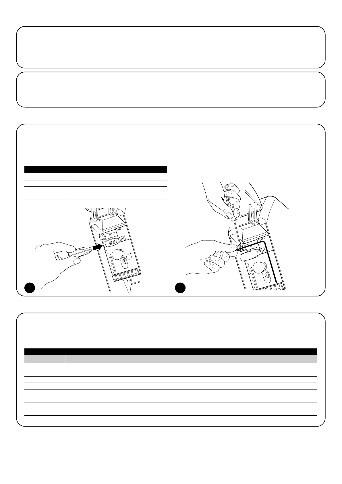
96
14) Informacje dodatkowe: funkcje specjalne
14.1) Funkcja “Zawsze otwórz”
Funkcja “Zawsze otwórz” pozwala na sterowanie poleceniem otwarcia, kiedy polecenie “Krok po kroku” trwa ponad 2 sekundy. Jest to przydatne
np. kiedy do zacisku “Krok po kroku” podłączamy styk zegara programującego tak aby w pewnych godzinach brama pozostawała cały czas
otwarta. Opcja ta jest zachowana przy każdym programowaniu wejścia Krok po kroku, za wyjątkiem programowania w trybie “Zespół Mieszkalny
2”. Patrz “Funkcja Krok po kroku” w Tabeli 4.
15) Działanie automatyki przy użyciu nadajnika i radioodbiornika typu “SM”
W centrali znajduje się złącze przeznaczone do instalacji
Radioodbiornika z wtykiem typu “SM” (Rys.13) w celu sterowania
automatyką za pomocą nadajnika (odbiornik i nadajnik stanowią
akcesoria opcjonalne). Cztery Wyjścia Odbiornika pozwalają na
przekazanie do Centrali następujących poleceń:
Jeśli nie jest stosowana antena wbudowana w LUCYB lub inny typ
zewnętrznej anteny, do zacisku anteny należy przykręcić sztywny
kabelek znajdujący się na wyposażeniu odbiornika (Rys.14)
14.2) Funkcja “Wykonaj manewr mimo wszystko”
W przypadku błędnego działania lub uszkodzenia jednego z urządzeń zabezpieczających, jest możliwe sterowanie bramą w trybie “W obecności
operatora”. Więcej informacji na ten temat znajdziesz w punkcie “Sterowanie przy niesprawnych urządzeniach zabezpieczających” znajdującym
się w załączniku “Zalecenia i środki ostrożności skierowane do użytkownika siłownika SOON”.
Wyjście N. 1 Polecenie “Krok po Kroku”
Wyjście N. 2 Polecenie “Otwarcie częściowe”
Wyjście N. 3 Polecenie “Otwiera”
Wyjście N. 4 Polecenie “Zamyka”
Tabela 6: Polecenia dla odbiornika SMXI, SMXIS
16) Automatyczna kontrola i diagnostyka nieprawidłowego działania
Podczas regularnego działania Centrala stale kontroluje procesy automatyki i może sygnalizować wystąpienie ewentualnych anomalii przy pomocy
wcześniej ustalonych sekwencji mignięć wydawanych przez lampę ostrzegawczą, światełko nocne i “Diodę BlueBUS” (mignięcia diagnostyczne
odnoszą się zawsze do ostatniej czynności wykonanej przez SOON). Poszczególnym przyczynom wystąpienia anomalii odpowiada różna liczba
mignięć, tak jak przedstawiono to w następującej tabeli:
Tabela 7: Sygnalizacja diagnostyczna
13 14
Liczba mignięć Przyczyna
1 Błąd synchronizacji BlueBUS
2 Zadziałanie Fotokomórki lub błąd Fototestu
3 Zbyt mała siła siłownika lub wykryta przeszkoda w czasie manewru
4 Interwencja urządzeń STOP
5 Błąd w parametrach pamięci
6 Interwencja wewnętrznego ogranicznika manewrów
7 Błąd w obwodach zasilania siłownika
8 Przeciążenie obwodów siłownika
Page 97
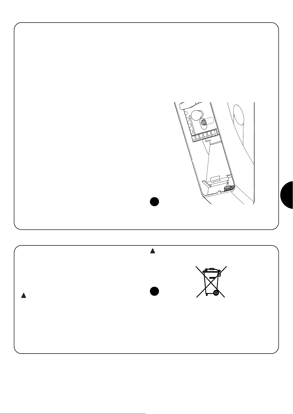
97
PL
17) Co robić gdy... (Poradnik - rozwiązywanie problemów)
Jest to krótki poradnik dotyczący rozwiązywania najczęściej
występujących problemów podczas montażu i programowania
automatyki.
•
...nie można wykonać żadnego manewru, a dioda “BlueBUS”
nie miga
- Upewnij się czy do siłownika SOON dochodzi zasilanie z sieci o
napięciu 230V. Sprawdź się czy nie zadziałały bezpieczniki F1 i F2.
Jeśli zadziałały, musisz znaleźć przyczynę uszkodzenia i wymienić
bezpieczniki na nowe o tych samych właściwościach i wartości prądu
•
...nie można wykonać żadnego manewru a lampa
ostrzegawcza jest zgaszona
- Upewnij się czy centrala rzeczywiście otrzymuje polecenie.
Potwierdzeniem dotarcia polecenia do wejścia Krok po kroku jest
zapalenie się odpowiedniej diody “Krok po kroku”. W przypadku
stosowania nadajnika, dioda “BlueBUS” musi mignąć szybko dwa razy.
•
...manewr nie rozpoczyna się a światełko nocne miga kilka
razy
- Policz liczbę mignięć i sprawdź w Tabeli xx co oznaczają
•
...podczas manewru jest wykonywany krótki ruch w
przeciwną stronę
- Wybrana siła może być zbyt niska do ruszenia bramy. Upewnij się czy
nie występują żadne przeszkody i ewentualnie wybierz wyższą siłę.
- Sprawdź czy zadziałało urządzenie zabezpieczające podłączone do
wejścia STOP.
•
...manewr jest wykonywany, ale urządzenie podłączone do
wyjścia FLASH nie działa
- Upewnij się czy urządzenie podłączone do wyjścia FLASH to
urządzenie, które zostalo zaprogramowane.
- Upewnij się czy w czasie gdy urządzenie powinno być zasilane, na
zacisku tego urządzenia rzeczywiście jest napięcie. Jeśli napięcie
jest, problem występuje po stronie urządzenia i musisz je zastąpić
innym o identycznych właściwościach. Jeśli jednak brak napięcia,
oznacza to przeciążenie elektryczne na wyjściu. Upewnij się czy nie
ma zwarcia na przewodzie.
•
...podczas procedury programowania pozycji migają
szybko dioda L1 lub L8
- Oznacza to, że została przekroczona maksymalna pozycja otwarcia
(miga szybko L1) lub zamknięcia (miga szybko L8).
- Jeśli miga dioda L1 przeprowadź manewr zamknięcia, aż do momentu
kiedy L1 przestanie szybko migać. Następnie zdejmij siłownik SOON z
wału sprężynowego, ustaw bramę w pozycji maksymalnego otwarcia i
ponownie zamontuj siłownik SOON w tej pozycji.
- Jeśli miga dioda L8, przeprowadź manewr otwarcia, dopóki L8 nie
przestanie szybko migać. Następnie zdejmij siłownik SOON z wału
sprężynowego, ustaw bramę w pozycji maksymalnego zamknięcia i
ponownie zamontuj siłownik SOON w tej pozycji.
15
Podobnie jak w przypadku montażu, również czynności związane z
demontażem muszą być wykonane przez wykwalifikowany personel
techniczny. Produkt ten składa się z różnego rodzaju materiałów,
niektóre z nich mogą być powtórnie użyte, inne muszą zostać poddane
utylizacji. Zasięgnij informacji odnośnie systemów recyklingu i utylizacji,
przewidzianych zgodnie z lokalnymi przepisami obowiązującymi dla tej
kategorii produktu.
Niektóre elementy produktu mogą zawierać substancje
szkodliwe lub niebezpieczne, które po wyrzuceniu, mogłyby
zaszkodzić środowisku lub zdrowiu ludzkiemu.
Zgodnie ze wskazaniem symbolu na rys. 16, zabrania się wyrzucania
tego produktu do odpadów domowych. Należy przeprowadzić
“segregację odpadów” na potrzeby utylizacji, według metod
przewidzianych lokalnymi przepisami lub zwrócić produkt sprzedawcy
podczas zakupu nowego, równorzędnego produktu.
Lokalne przepisy mogą przewidywać poważne sankcje w
przypadku nielegalnej utylizacji produktu.
!
!
16
18) Utylizacja
Page 98

Dichiarazione CE di conformità / EC Declaration of Conformity
Dichiarazione CE di conformità secondo Direttiva 98/37/CE, Allegato II, parte B (dichiarazione CE di conformità del fabbricante)
EC Declaration of Conformity according to Directive 98/37/EC, Annexe II, part B
Numero
/ Number:
245/SOON Revisione
/ Revision:
0
Il sottoscritto Lauro Buoro in qualità di Amministratore Delegato, dichiara sotto la propria responsabilità che il prodotto:
The undersigned Lauro Buoro, managing director, declares under his sole responsibility that the following product:
Nome produttore /
Manufacturer’s name
: NICE s.p.a.
Indirizzo /
Address:
Via Pezza Alta 13, 31046 Z.I. Rustignè, Oderzo (TV) Italia
Tipo /
Type:
Motoriduttore elettromeccanico 24Vcc. con centrale incorporata
24Vcc
electromechanical gearmotor with incorporated control unit
Modelli /
Models:
SO2000
Accessori /
Accessories:
SMXI, SMXIS, ONEXI
PS124
Risulta conforme a quanto previsto dalla direttiva comunitaria:
Satisfies the essential requirements of the following Directives:
• 98/37/CE (89/392/CEE modificata) DIRETTIVA 98/37/CE DEL PARLAMENTO EUROPEO E DEL CONSIGLIO del 22 giugno 1998 concer-
nente il ravvicinamento delle legislazioni degli Stati membri relative alle macchine
Secondo Allegato II, parte B (dichiarazione CE del fabbricante)
98/37/EC (89/392/EEC amended); DIRECTIVE 98/37/EC OF THE EUROPEAN PARLIAMENT AND COUNCIL of 22 June 1998 regarding
the approximation of member state legislation related to machinery
Conformity according to Directive EC, Annexe II, part B
Come previsto dalla direttiva 98/37/CE si avverte che non è consentita la messa in servizio del prodotto sopra indicato finché la macchina,
in cui il prodotto è incorporato, non sia stata identificata e dichiarata conforme alla direttiva 98/37/CE.
As envisaged in the directive 98/37/EC, start-up of the product specified above is not admitted unless the machine, in which the product is
incorporated, has been identified and declared as conforming to directive 98/37/EC.
Inoltre il prodotto risulta conforme a quanto previsto dalle seguenti direttive comunitarie, così come modificate dalla Direttiva 93/68/CEE del
consiglio del 22 Luglio 1993:
The product also complies with the requirements of the following EC directives, as amended by Directive 93/68/EEC of the European Council of 22 July 1993:
• 73/23/CEE DIRETTIVA 73/23/CEE DEL CONSIGLIO del 19 febbraio 1973 concernente il riavvicinamento delle legislazioni degli Stati mem-
bri relative al materiale elettrico destinato ad essere adoperato entro taluni limiti di tensione
Secondo le seguenti norme armonizzate: EN 60335-1:1994; EN 60335-2-95: 2001.
73/23/EEC; DIRECTIVE 73/23/EEC OF THE EUROPEAN COUNCIL of 19 February 1973 regarding the approximation of member state legislation related to electrical material destined for use within specific voltage limits
According to the following harmonised standard: EN 60335-1:1994; EN 60335-2-95: 2001.
• 89/336/CEE DIRETTIVA 89/336/CEE DEL CONSIGLIO del 3 maggio 1989, per il riavvicinamento delle legislazioni degli Stati membri rela-
tive alla compatibilità elettromagnetica
Secondo le seguenti norme armonizzate: EN 61000-6-2:2001; EN 61000-6-3:2001+A1:2004
89/336/EEC; DIRECTIVE 89/336/EEC OF THE EUROPEAN COUNCIL of 3 May 1989, regarding the approximation of member state legislation related to electromagnetic compatibility
According to the following harmonised standards: EN 61000-6-2:2001; EN 61000-6-3:2001+A1:2004
Inoltre risulta conforme; limitatamente per le parti applicabili, alle seguenti norme /
It also complies, within the constraints of applicable parts,
with the following standards:
EN 60335-1:2002+A1:2004+A11:2004, EN 60335-2-103:2003, EN 13241-1:2003; EN 12453:2002; EN 12445:2002; EN 12978:2003
Oderzo, 9 Maggio 2006 Lauro Buoro
Oderzo, 9 May 2006
(Ammnistratore Delegato)
(Managing Director)
98
Page 99

Page 100

ISTSO.4865 REV.02 del 05-09-2007
Nice Romania
Cluj Napoca
Tel/Fax +40.264.45.31.27
info@ro.niceforyou.com
Nice Deutschland
Gelnhausen-Hailer
Tel. +49.60.51.91.52-0
Fax +49.60.51.91.52-119
info@de.niceforyou.com
Nice China
Shanghai
Tel. +86.21.575.701.46
+86.21.575.701.45
Fax +86.21.575.701.44
info@cn.niceforyou.com
Nice USA Inc.
Jacksonville, FI.
Tel. +001.904.786.7133
Fax +001.904.786.7640
info@us.niceforyou.com
www.niceforyou.com
Headquarter
Nice SpA
Oderzo TV Italia
Tel. +39.0422.85.38.38
Fax +39.0422.85.35.85
info@niceforyou.com
Nice in Italy
Nice Padova
Sarmeola di Rubano PD Italia
Tel. +39.049.89.78.93.2
Fax +39.049.89.73.85.2
infopd@niceforyou.com
Nice Roma
Roma Italia
Tel. +39.06.72.67.17.61
Fax +39.06.72.67.55.20
inforoma@niceforyou.com
Nice worldwide
Nice France
Buchelay
Tel. +33.(0)1.30.33.95.95
Fax +33.(0)1.30.33.95.96
info@fr.niceforyou.com
Nice Rhône-Alpes
Decines Charpieu France
Tel. +33.(0)4.78.26.56.53
Fax +33.(0)4.78.26.57.53
infolyon@fr.niceforyou.com
Nice France Sud
Aubagne France
Tel. +33.(0)4.42.62.42.52
Fax +33.(0)4.42.62.42.50
infomarseille@fr.niceforyou.com
Nice Belgium
Leuven (Heverlee)
Tel. +32.(0)16.38.69.00
Fax +32.(0)16.38.69.01
info@be.niceforyou.com
Nice España Madrid
Tel. +34.9.16.16.33.00
Fax +34.9.16.16.30.10
info@es.niceforyou.com
Nice España Barcelona
Tel. +34.9.35.88.34.32
Fax +34.9.35.88.42.49
info@es.niceforyou.com
Nice Polska
Pruszków
Tel. +48.22.728.33.22
Fax +48.22.728.25.10
info@pl.niceforyou.com
Nice UK
Chesterfield
Tel. +44.87.07.55.30.10
Fax +44.87.07.55.30.11
info@uk.niceforyou.com
 Loading...