

Page 1
Instructions and warnings for the fitter
Istruzioni ed avvertenze per l’installatore
Instructions et recommandations pour l’installateur
Anweisungen und Hinweise für den Installateur
Instrucciones y advertencias para el instalador
Instrukcje i uwagi dla instalatora
Radio receiver
SMX2 SMX2R
Page 2
2
Product description
SMX2 and SMX2R are dual-channel radio receivers that are
designed for general use and differentiate themselves for their compatibility with transmitters.
SMX2 SMILO
SMX2R FLOR and VERY VR
The peculiarity of compatible transmitters is that the identification
code is different for each transmitter. Therefore, in order to recognise
a determined transmitter, the recognition code must be memorised.
This operation must be repeated for each transmitter to be used.
The receivers are provided with power and 2 outputs on the output
cabling:
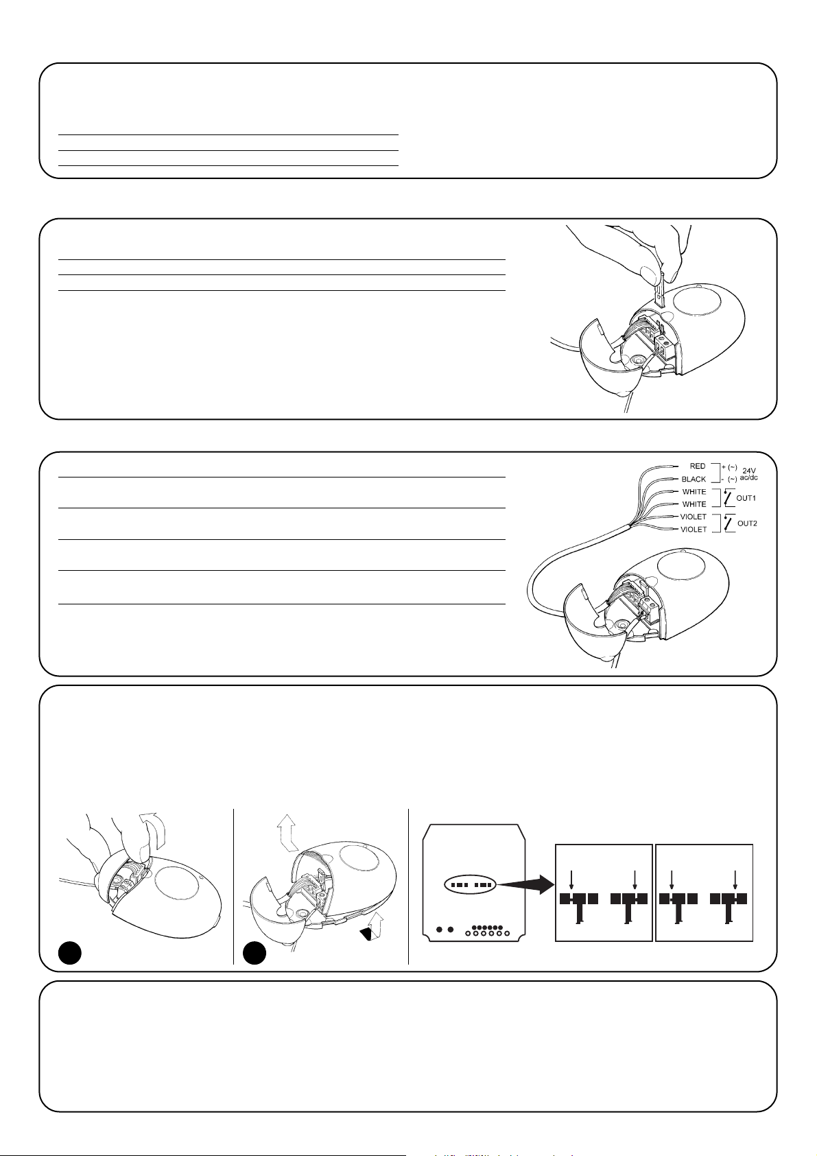
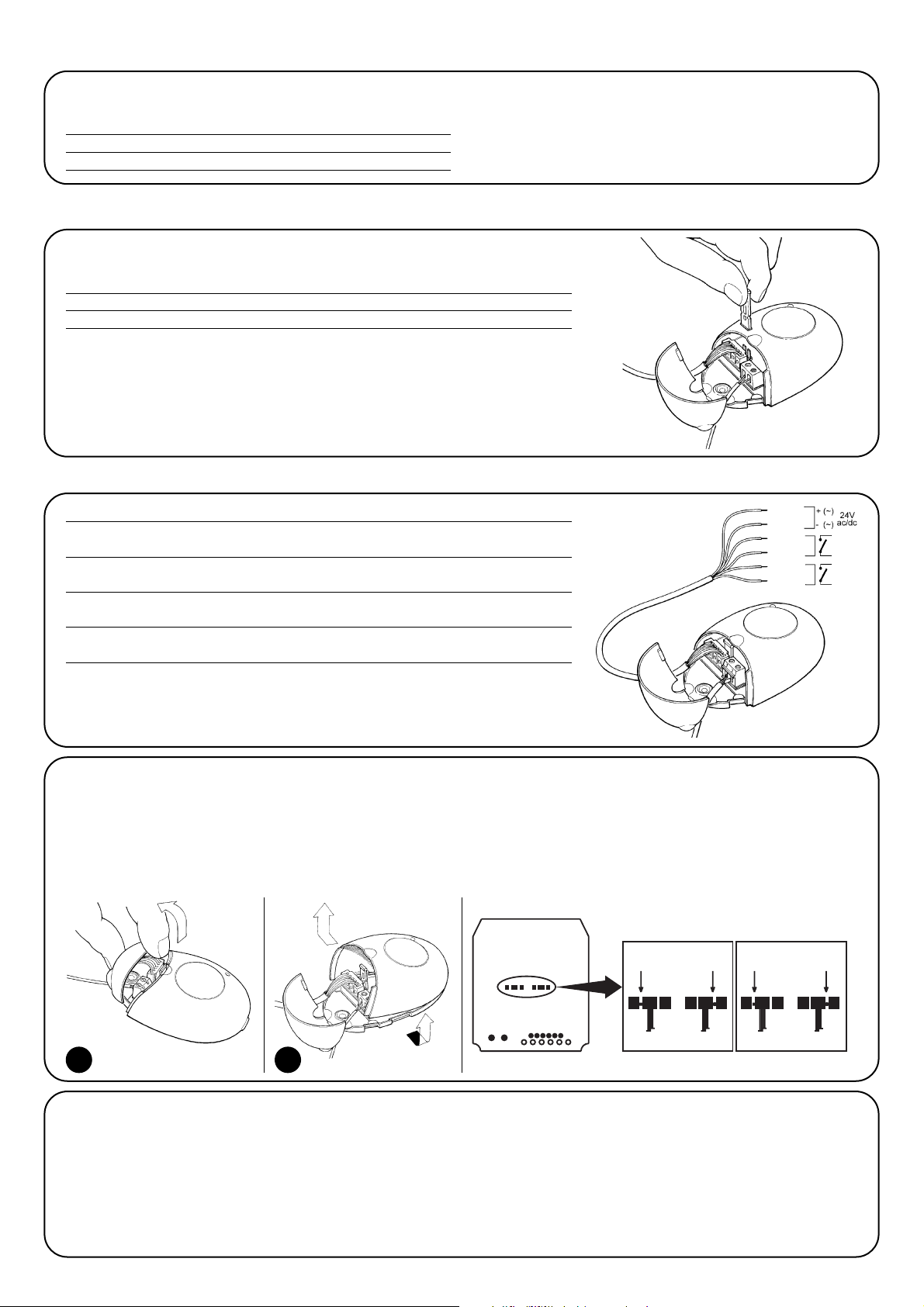
Power input selectio
Insert or remove a jumper from its seat to select power input:
Jumper not inserted 24 V ac/dc Voltage limits: 18 ÷ 24 V
Jumper inserted 12 V ac/dc Voltage limits: 10 ÷ 18 V
The receivers are provided with power and 2 outputs on the output cabling:
Red / Black POWER INPUT
Red= Positive, Black= Negative. Position is not important if alternating current is selected
White / White RELAY 1 OUTPUT
Free contact of a normally open relay
Purple / Purple RELAY 2 OUTPUT
Free contact of a normally open relay
Terminals 1, 2 AERIAL
Aerial signal input (terminal 1 braid, terminal 2 core)
Installation
Electrical connections
Contact in receiver output
The outputs are commanded by a relay with a normally open “NO” contact. If a normally closed “NC” type of contact is needed: disconnect
the power supply from the receiver, open the box, first from below as shown in Fig.5a and then from above as shown in Fig.5b, carefully
remove the board and work on the welding side of the receiver as follows:
1. Cut the part of the track at point X.
N.B.: this operation can be performed both for relay N°1 and for relay N°2.
2. Join the pads in point Y with a spot of solder.
Installing the aerial
The receiver requires an ABF or ABFKIT type aerial to work properly;
without an aerial the range is limited to just a few metres. The aerial must
be installed as high as possible; if there are metal or reinforced concrete
structures nearby you can install the aerial on top. If the cable supplied
with the aerial is too short, use a coaxial cable with 50-Ohm impedance
(e.g. low dispersion RG58), the cable must be no longer than 10 m.
If the aerial is installed in a place that is not connected to earth
(masonry structures), the braid’s terminal can be earthed to provide
a larger range of action. The earth point must, of course, be local
and of good quality. If an ABF or ABFKIT aerial cannot be installed,
you can get quite good results using the length of wire supplied with
the receiver as the aerial, laying it flat.
5a 5b
RELAY 1 RELAY 2
109-A LS
RELE’ 2
X
NC
NO
NO
X
NC
NO
RELE’ 1
NC
NO
YY
NC
Page 3

GB
3
Memorising a remote control
When the memorisation phase is activated, any transmitter correctly recognised within the reception range of
the radio is memorised. Consider this aspect with care
and remove the aerial if necessary to reduce the capacity
of the receiver.
The procedures for memorising the remote controls must be performed within a certain time limit; please read and understand the
whole procedure before starting.
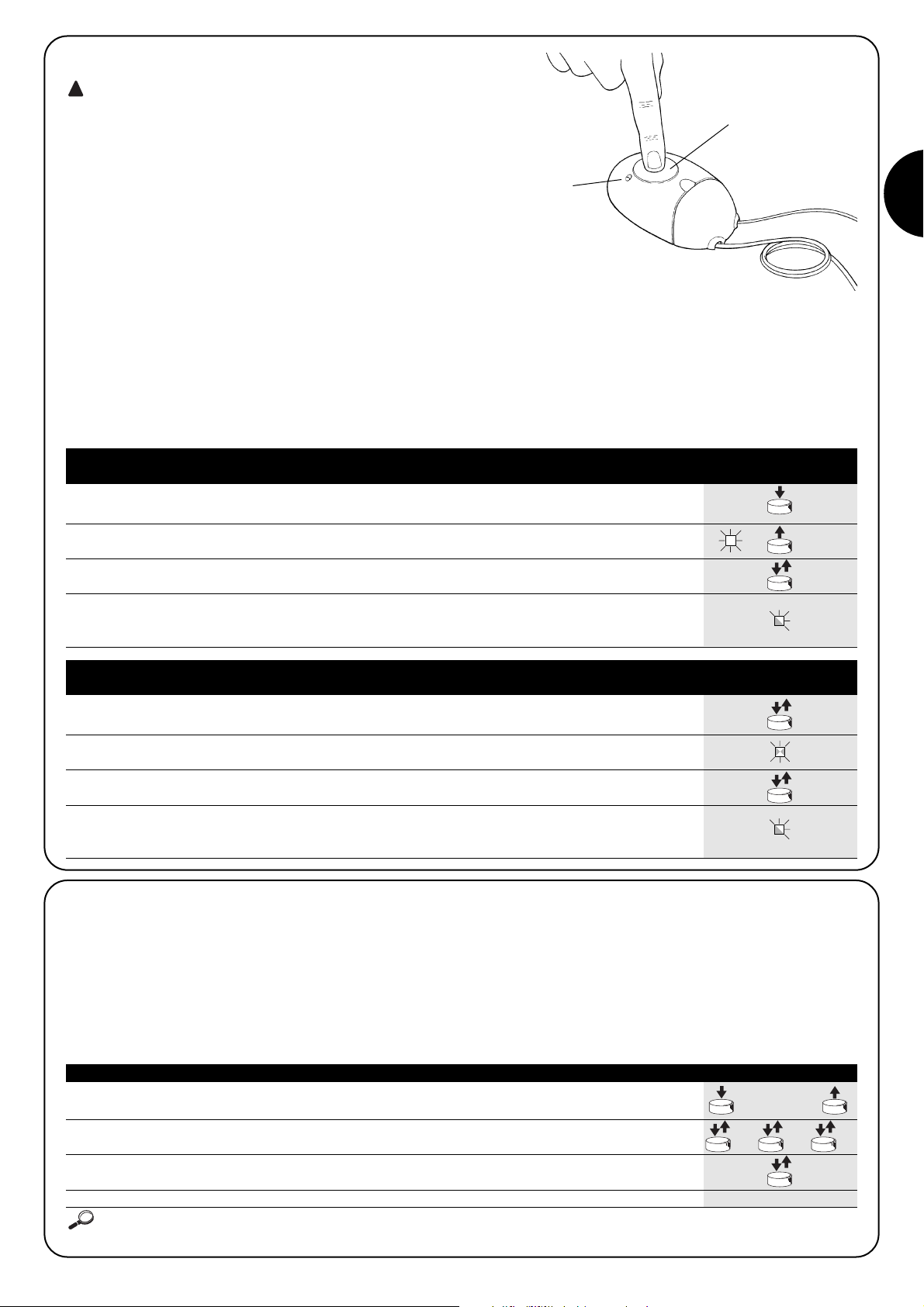
In order to carry out the following procedure, it is necessary to use
the button located on the box of the radio receiver (reference A), and
the corresponding LED (reference B) to the left of the button.
During the transmitter code memorisation phase, one of these
options may be chosen:
Mode I. Each transmitter button activates the corresponding output
in the receiver, that is, button 1 activates output 1, button 2 activates
output 2, and so on. In this case there is a single memorisation
phase for each transmitter; during this phase, it doesn’t matter
which button is pressed and just one memory sector is occupied.
Mode II. Each transmitter button can be associated with a particular output in the receiver, e.g., button 1 activates output 2, button 2
activates output 1, and so on. In this case, the transmitter must be
memorised, pressing the required button, for each output to activate. Naturally, each button can activate just one output while the
same output can be activated by more than one button. One memory section is occupied for each button.
!
x5s
1s 1s 1s
x1
1. Press the button on the NEW transmitter for at least 5 seconds and then release
2. Press the button on the OLD transmitter 3 times slowly
3. Press the button on the NEW transmitter slowly and then release
N.B.: If there are other transmitters to memorise, repeat the above steps for each new transmitter
Up to a maximum of 256 transmitters can be memorised in the receiver. No one transmitter can be cancelled; all the codes must be
deleted. For more advanced functions use the appropriate programming unit.
Table “B3” Remote Memorising Example
TX
TXTXTX
TX
TX
Remote memorising
It is possible to enter a new transmitter in the receiver memory without using the keypad. A previously memorised and operational
remote control must be available. The new transmitter will “inherit”
the characteristics of the previously memorised one. Therefore, if the
first transmitter is memorised in mode I, the new one will also be
memorised in mode I and any of the buttons of the transmitter can
be pressed. If the first transmitter is memorised in mode II the new
one will also be memorised in mode II but the button activating the
required output must be pressed on the first transmitter as must the
button required to be memorised on the second. You need to read
all the instructions in advance so you can perform the operations in
sequence without interruptions. Now, with the two remote controls
(the NEW one requiring code memorisation and the OLD one that is
already memorised), position yourself within the operating range of
the radio controls (within maximum range) and carry out the instructions listed in the table.
2s
x3
3s
2s
x3
1. Press and hold down the receiver button for at least 3 seconds
2. Release the button when the Led lights up
3.
Within 10 seconds press the 1st button on the transmitter to be memorised,
holding it down for at least 2 seconds
N.B.: If the procedure was memorised correctly, the Led on the receiver will flash 3 times.
If there are other transmitters to memorise, repeat step 3 within another 10 seconds
The memorisation phase finishes if no new codes are received for 10 seconds.
Table “B1” Mode I memorising Example
(each button activates the corresponding output in the receiver)
1. Press and release the receiver button as many times as the number of the
desired output (twice for output no. 2)
2. Make sure the Led flashes as many times as the number of the desired
output (2 flashes for output no. 2).
3. Within 10 seconds press the desired button on the transmitter to be memorised,
holding it down for at least 2 seconds.
N.B.: If the procedure was memorised correctly, the Led on the receiver will flash 3 times.
If there are other transmitters to memorise, repeat step 3 within another 10 seconds
The memorisation phase finishes if no new codes are received for 10 seconds.
Table “B2” Mode II memorising Example
(each button can be associated with a particular output)
RX
RX
TX
TX
RX
A
B
Page 4
4
x3
3°
x5
Deleting all transmitters
All the memorised codes can be deleted as follows:
1. Press the receiver button and hold it down
2. Wait for the Led to light up, then wait for it to switch off
and then wait for it to flash 3 times
3. Release the button exactly during the third flash
N.B.: if the procedure was performed correctly, the Led will flash 5 times after a few moments.
Table “B4” Deleting all transmitters Example
RX
RX
Maintenance
The receivers and transmitters, being electronic components, do not
require any special maintenance. In any case, check the materials
that the device is made of every 6 months for signs of wear, oxidation or presence of foreign bodies.
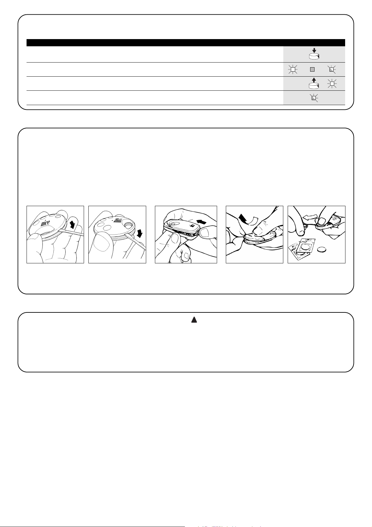
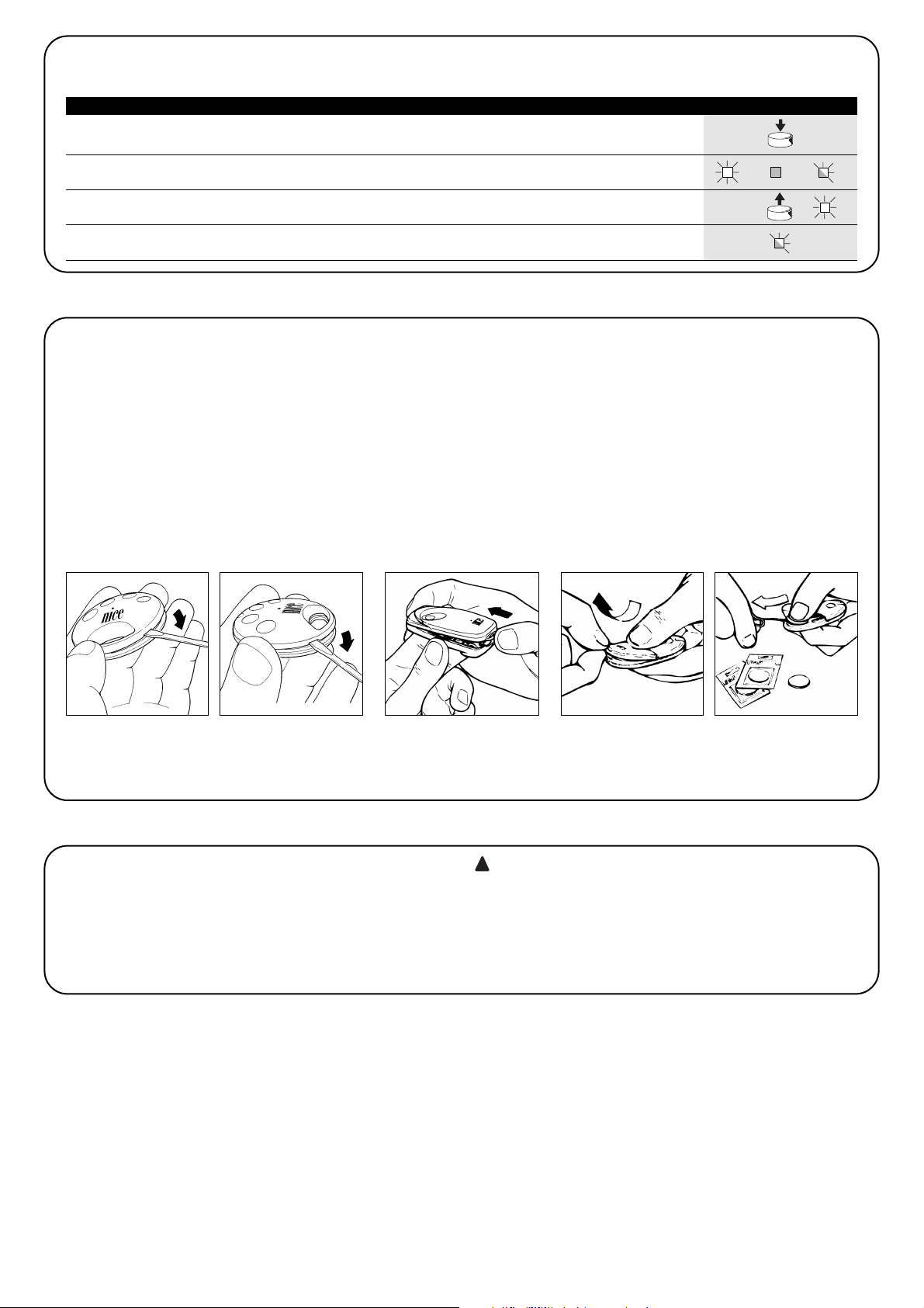
Replacing the Remote Control Battery: If your radio control,
after a period of time, seems not to work as well, or not to work at
all, it may simply be that the battery is exhausted (depending on the
type of use, it may last from several months up to one year and
more). In this case you will see that the light confirming the transmission is weak, or does not come on, or comes on only briefly.
Before calling the installation technician try exchanging the battery
with one from another operating transmitter: if the problem is caused
by a low battery, just replace it with another of the same type.
Disposal
This product is made from various kinds of materials, some of which
can be recycled while others must be scrapped.
Separate as best you can the parts that can or must be recycled
from those that must be disposed of otherwise, such as plastic
parts, electronic boards, batteries, etc.
Sort the various materials and consign them to local authorized recycling and disposal centres
Certain electronic components, as well as batteries,
might contain polluting substances. Do not pollute the
environment.
Enquire about the recycling or disposal systems available
and proceed in compliance with the regulations locally in
force.
!
SM2 - SM4 Very VR
FLO*R-S
FLO*R-SC
FLO*R-M
Page 5
GB
5
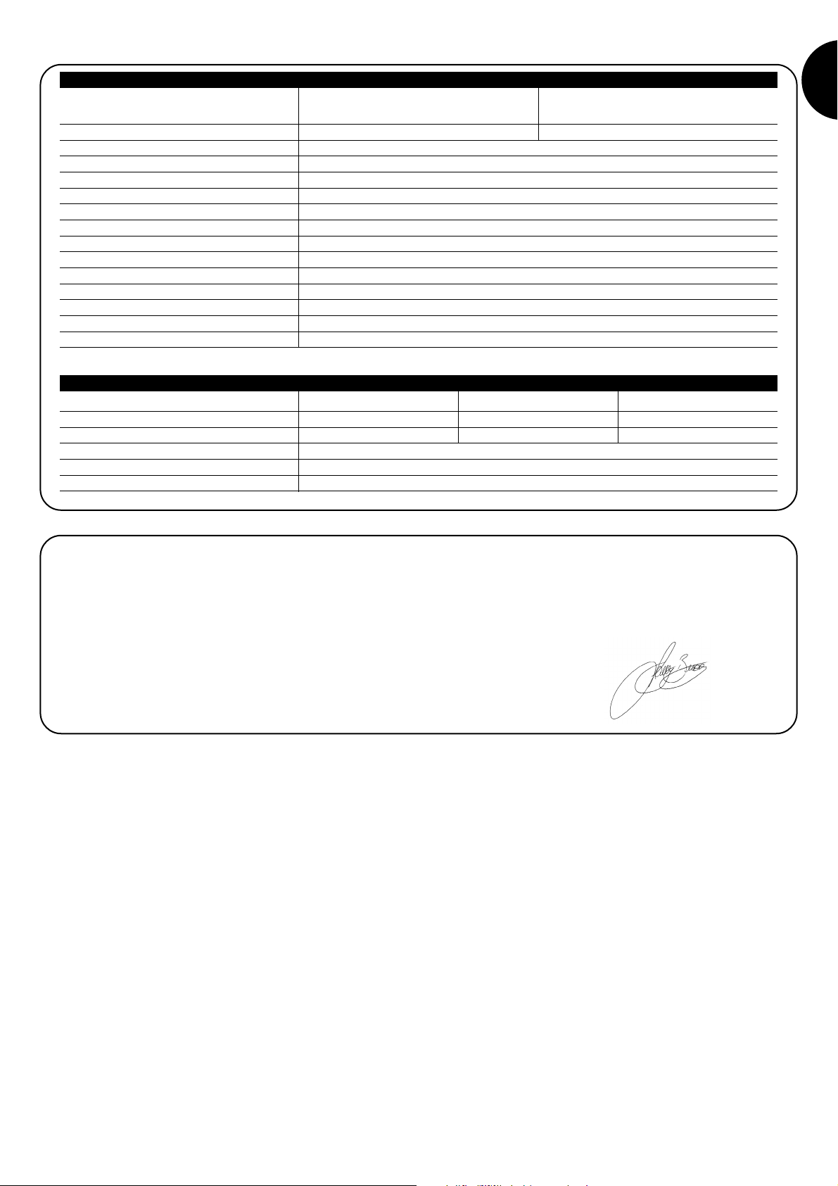
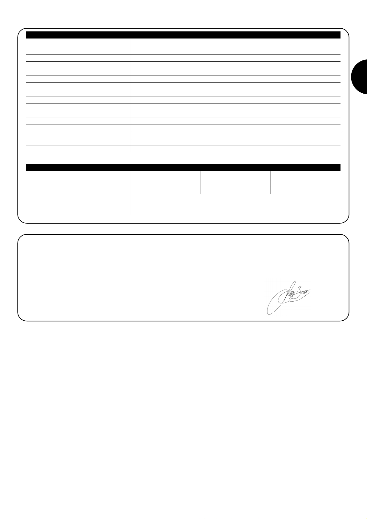
Decoding rolling code rolling code
64 bit SMILO 52 bit FLOR
Transmitter compatibility SMILO FLOR, VERY VR
Power supply without jumper = 24 V typical Limits from 18 to 24V ac or dc
with jumper = 12 V typical. Limits from 10 to 18V ac or dc
Absorption when idle 10mA at 24Vac
2 live relays absorption 60mA at 24Vac
Frequency 433.92MHz
Sensitivity better than 0.5µV
No. of relays 2
Relay contact normally open max. 0.2A and 50 V
Pickup Time approx. 200ms (reception of 2 correct codes)
Drop-out Time approx. 300ms from the last correct code
Operating temperature -10°C at +55°C
Protection class of the casing IP30D
Dimensions and weight 86x57 h22mm, weight 55g
Technical characteristics
Receiver SMX2 SMX2R
No. of buttons (N=*) 1 – 2 – 4 2 2 – 4
Power supply 12Vdc Batt. 23A 6Vdc Lithium Batt. 12Vdc Batt. 23A
Input 10mA 10mA 25mA
Frequency 433.92Mhz
Operating temp. -40°C ÷ +80°C
Radiated power 100mW
Transmitters
FLO*R-S FLO*R-SC FLO*R-M
Very VR SM2-SM4
Declaration of conformity
N°: 146/SMX2 SMX2R Rev01
Nice S.p.a., Via Pezza Alta 13, 31046 Rustignè di Oderzo (TV) Italy
NICE S.p.a. declares that radio receiver models SMX2, SMX2R and the relative FLO1R-S, FLO2R-S, FLO4R-S, FLO1R-SC, FLO2R-SC,
FLO4R-SC, FLO2R-M, FLO4R-M, VR, SM2, SM4 transmitters conform to the essential requisites specified in Directive R&TTE 1999/5/CE,
for the use the devices have been manufactured for. Manufactured in Class 1, Sub-class 20.
Fabbricato in Classe 1, Sub-classe 20
Date 19th March 2004 Managing Director
Lauro Buoro
Page 6
6
Descrizione del prodotto
SMX2 e SMX2R sono ricevitori radio a 2 canali destinati ad un uso
universale e si differenziano per la compatibilità con i trasmettitori.
SMX2 SMILO
SMX2R FLOR and VERY VR
I trasmettitori compatibili hanno la particolarità che il codice di riconoscimento risulta diverso per ognuno. Per permettere al ricevitore
di riconoscere un determinato trasmettitore occorre procedere alla
memorizzazione del codice di riconoscimento. Questa operazione di
inserimento va ripetuta per ogni trasmettitore che si voglia utilizzare.
Selezione dell’alimentazione
Attraverso un ponticello da inserire o togliere dall’apposito innesto e possibile selezionare
l’alimentazione:
Ponticello non inserito 24 V ac/dc Limiti di tensione: 18 ÷ 28 V
Ponticello inserito 12 V ac/dc Limiti di tensione: 10 ÷ 18 V
Il ricevitore dispone di alimentazione e di 2 uscite sul cablaggio in uscita:
Rosso / Nero ALIMENTAZIONE
Rosso = Positivo, Nero = Negativo. In corrente alternata è indifferente
Bianco / Bianco USCITA 1° RELÉ
Contatto pulito di un relé normalmente aperto
Viola / Viola USCITA 2° RELÉ
Contatto pulito di un relé normalmente aperto
Morsetti 1, 2 ANTENNA
Ingresso segnale antenna (morsetto 1 calza, morsetto 2 anima)
Installazione
Collegamenti elettrici
Contatto in uscita nel ricevitore
Le uscite sono comandate da un relè con contatto di tipo normalmente aperto “NA”. Nel caso sia necessario un contatto di tipo normalmente chiuso “NC”: togliere alimentazione al ricevitore, aprire il box, prima dal basso come illustrato in Fig.5a e poi dall’alto come in Fig.5b,
quindi estrarre la scheda con cura ed operare sul lato saldature del ricevitore come descritto:
1. Tagliare il tratto di traccia nel punto X .
Nota: questa operazione può essere fatta sia per il relè N°1 che per il relè N°2.
2. Unire con una goccia di stagno le piazzole nel punto Y.
Installazione antenna
Per ottenere un buon funzionamento il ricevitore necessita di un’antenna di tipo ABF o ABFKIT; senza antenna la portata si riduce a pochi
metri. L’antenna deve essere installata più in alto possibile; in presenza di strutture metalliche o di cemento armato, installare l’antenna al di
sopra di queste. Se il cavo in dotazione all’antenna è troppo corto,
impiegare cavo coassiale con impedenza 50 ohm (es. RG58 a bassa
perdita), il cavo non deve superare la lunghezza di 10 m.
Qualora l’antenna sia installata dove non esiste un buon piano di terra (strutture murarie) è possibile collegare il morsetto della calza a
terra ottenendo così una maggiore portata. Naturalmente la presa di
terra deve essere nelle vicinanze e di buona qualità. Nel caso non sia
possibile installare l’antenna accordata ABF o ABFKIT si possono
ottenere dei discreti risultati usando come antenna lo spezzone di filo
fornito col ricevitore, montato disteso.
5a 5b
ROSSO
NERO
BIANCO
BIANCO
VIOLA
VIOLA
USCITA1
USCITA2
109-A LS
NA
X
RELE' 2
NC
NA
RELE' 1
X
NC
NC
NA
YY
NC
NA
Page 7
GB
I
7
Memorizzazione di un telecomando
Quando si attiva la fase di memorizzazione, qualsiasi
trasmettitore correttamente riconosciuto nel raggio di
ricezione della radio viene memorizzato. Valutare con
attenzione questo aspetto, eventualmente staccare l’antenna per ridurre la capacità del ricevitore.
Le procedure per la memorizzazione dei telecomandi hanno un tempo limite per essere eseguite; è necessario quindi leggere e comprendere tutta la procedura prima di iniziare le operazioni.
Per eseguire la procedura seguente, è necessario utilizzare il pulsante presente sul box del ricevitore radio (riferimento A), ed il rispettivo
Led (riferimento B) alla sinistra del tasto.
Nella fase di memorizzazione del codice del trasmettitore è possibile scegliere tra queste 2 opzioni:
Modo I. Ogni tasto del trasmettitore attiva la corrisponde uscita nel
ricevitore, cioè il tasto 1 attiva l’uscita 1, il tasto 2 attiva l’uscita 2, e
così via. In questo caso c’è un’unica fase di memorizzazione per
ogni trasmettitore, durante questa fase non ha importanza quale
tasto viene premuto, e viene occupato un solo posto in memoria.
Modo II. Ad ogni tasto del trasmettitore può essere associata una
particolare uscita del ricevitore, esempio il tasto 1 attiva l’uscita 2, il
tasto 2 attiva l’uscita 1, eccetera. In questo caso bisogna memorizzare il trasmettitore, premendo il tasto desiderato, per ogni uscita da
attivare. Naturalmente ogni tasto può attivare una sola uscita, mentre la stessa uscita può essere attivata da più tasti. Viene occupato
un posto in memoria per ogni tasto.
!
x5s
1s 1s 1s
x1
1. Premere per almeno 5 secondi il tasto sul NUOVO trasmettitore, poi rilasciare
2. Premere lentamente per 3 volte il tasto sul VECCHIO trasmettitore
3. Premere lentamente per 1 volta il tasto sul NUOVO trasmettitore, poi rilasciare
Nota: se ci sono altri trasmettitori da memorizzare, ripetere tutti i passi per ogni nuovo trasmettitore
Nel ricevitore posso essere memorizzati fino ad un massimo di 256 trasmettitori. Non è prevista la cancellazione di un singolo trasmettitore ma solo la cancellazione totale di tutti i codici. Per funzioni più avanzate utilizzare l’apposita unità di programmazione.
Tabella “B3” Memorizzazione a distanza Esempio
TX
TXTXTX
TX
TX
Memorizzazione a distanza
E’ possibile memorizzare un nuovo trasmettitore nella memoria del
ricevitore senza agire direttamente sul tastino. E’ necessario disporre di un telecomando già memorizzato e funzionante. Il nuovo trasmettitore “erediterà” le caratteristiche di quello già memorizzato.
Quindi se il primo trasmettitore è memorizzato in modo I anche il
nuovo sarà memorizzato in modo I e si potranno premere uno qualunque dei tasti dei trasmettitori. Se il primo trasmettitore è memorizzato in modo II anche il nuovo sarà memorizzato in modo II
ma occorre premere, nel primo trasmettitore il tasto che attiva l’uscita desiderata, e nel secondo trasmettitore il tasto che si vuol
memorizzare. E’ necessario leggere tutte le istruzioni per poi eseguire le operazioni una dopo l’altra senza interruzioni. Ora con i due
telecomandi che chiameremo NUOVO quello con il codice da inserire, e VECCHIO quello già memorizzato, porsi nel raggio di azione
dei radiocomandi (entro la portata massima) ed eseguire i passi
riportati in tabella.
2s
x3
3s
2s
x3
1. Premere e tenere premuto il pulsante sul ricevitore per almeno 3 secondi
2. Quando il Led si accende, rilasciare il pulsante
3.
Entro 10 secondi premere per almeno 2 secondi il 1° tasto del trasmettitore
da memorizzare
Nota: Se la memorizzazione è andata a buon fine il Led sul ricevitore farà 3 lampeggi.
Se ci sono altri trasmettitori da memorizzare, ripetere il passo 3 entro altri 10 secondi.
La fase di memorizzazione termina se per 10 secondi non vengono ricevuti nuovi codici.
Tabella “B1” Memorizzazione modo I Esempio
(ogni tasto attiva la corrispondente uscita nel ricevitore)
1.
Premere e rilasciare il pulsante sul ricevitore un numero di volte uguale
all'uscita desiderata ( 2 volte per uscita n°2)
2. Verificare che il Led emetta un numero di lampeggi uguali all'uscita voluta
( 2 lampeggi se uscita n°2).
3.
Entro 10 secondi premere per almeno 2 secondi il tasto desiderato del
trasmettitore da memorizzare
Nota: Se la memorizzazione è andata a buon fine il Led sul ricevitore farà 3 lampeggi.
Se ci sono altri trasmettitori da memorizzare, ripetere il passo 3 entro altri 10 secondi.
La fase di memorizzazione termina se per 10 secondi non vengono ricevuti nuovi codici.
Tabella “B2” Memorizzazione modo II Esempio
(ad ogni tasto può essere associata una particolare uscita )
RX
RX
TX
TX
RX
A
B
Page 8
8
x3
3°
x5
Cancellazione di tutti i trasmettitori
E’ possibile cancellare tutti i codici presenti in memoria con la seguente procedura:
1. Premere e tenere premuto il pulsante sul ricevitore
2. Aspettare che il Led si accenda, poi aspettare che si spenga,
quindi aspettare che emetta 3 lampeggi
3. Rilasciare il tasto esattamente durante il 3° lampeggio
Nota: se la procedura è andata a buon fine, dopo qualche istante, il Led emetterà 5 lampeggi.
Tabella “B4” Cancellazione di tutti i trasmettitori Esempio
RX
RX
Manutenzione
I ricevitori ed i trasmettitori come parti elettroniche, non necessitano
di alcuna manutenzione particolare. Verificare comunque ogni 6 mesi
lo stato di deterioramento dei materiali che compongono il prodotto
con particolare attenzione a fenomeni di usura, ossidazione, presenza di corpi estranei.
Sostituzione pila del telecomando: se il vostro radiocomando
dopo qualche tempo vi sembra funzionare peggio, oppure non
funzionare affatto, potrebbe semplicemente dipendere
dall’esaurimento della pila (a seconda dell’uso, possono trascorrere
da diversi mesi fino ad oltre un anno).
Ve ne potete accorgere dal fatto che la spia di conferma della trasmissione non si accende, è fioca, oppure si accende solo per un
breve istante.
Prima di rivolgervi all’installatore provate a scambiare la pila con
quella di un altro trasmettitore eventualmente funzionante: se questa
fosse la causa dell’anomalia, sarà sufficiente sostituire la pila con
altra dello stesso tipo.
Smaltimento
Questo prodotto è costituito da vari tipi di materiali, alcuni possono
essere riciclati, altri dovranno essere smaltiti.
Separare per quanto possibile le parti che possono o devono essere riciclate o smaltite in modo diverso, ad esempio le parti plastiche,
le schede elettroniche, le batterie ecc.
Smistare ed affidare i vari materiali così separati ai centri abilitati al
recupero ed allo smaltimento previsti a livello locale
Alcuni componenti elettronici e le batterie potrebbero
contenere sostanze inquinanti, non disperderli nell’ambiente. Informatevi sui sistemi di riciclaggio o smaltimento attenendovi alle norme in vigore a livello locale.
!
SM2 - SM4 Very VR
FLO*R-S
FLO*R-SC
FLO*R-M
Page 9
I
9
Decodifica: Rolling code Rolling code
a 64 bit SMILO a 52 bit FLOR
Compatibilità trasmettitori: SMILO FLOR, VERY VR
Alimentazione: senza ponticello = 24V tipici. Limiti da 18 a 24V continua o alternata
con ponticello = 12V tipici. Limiti da 10 a 18V continua o alternata
Assorbimento a riposo: 10mA a 24Vac
Assorbimento 2 relè attivi: 60mA a 24Vac
Frequenza 433.92MHz
Sensibilità migliore di: 0.5µV
N° relè: 2
Contatto relè: normalmente aperto max 0.5A e 50V
Tempo eccitazione: circa 200ms (ricezione di 2 codici corretti)
Tempo diseccitazione: circa 300ms dall’ultimo codice corretto
Temperatura di funzionamento: -10°C a +55°C
Grado di protezione del contenitore: IP30D
Dimensioni e peso: 86x57 h22mm, peso 55g
Caratteristiche tecniche
Ricevitori SMX2 SMX2R
N° tasti (N=*) 1 – 2 – 4 2 2 – 4
Alimentazione 12Vdc Batt. 23A 6Vdc Batt. Litio 12Vdc Batt. 23A
Assorbimento 10mA 10mA 25mA
Frequenza 433.92Mhz
Temp. di funzionamento -40°C ÷ +80°C
Potenza irradiata 100mW
Trasmettitori
FLO*R-S FLO*R-SC FLO*R-M
Very VR SM2-SM4
Dichiarazione di conformità
N°: 146/SMX2 SMX2R Rev01
Nice S.p.a., Via Pezza Alta 13, 31046 Rustignè di Oderzo (TV) Italia
NICE S.p.a. dichiara che i ricevitori radio modelli SMX2, SMX2R ed i relativi trasmettitori FLO1R-S, FLO2R-S, FLO4R-S, FLO1R-SC, FLO2RSC, FLO4R-SC, FLO2R-M, FLO4R-M, VR, SM2, SM4 sono conformi ai requisiti essenziali richiesti dalla Direttiva R&TTE 1999/5/CE, per l’uso cui gli apparecchi sono destinati.
Fabbricato in Classe 1, Sub-classe 20
Data:19 Marzo 2004 Amministratore Delegato
Lauro Buoro
Page 10

10
Description du produit
SMX2 et SMX2R sont des récepteurs radio à 2 canaux destinés à un usage universel qui se caractérisent par la compatibilité avec les émetteurs.
SMX2 SMILO
SMX2R FLOR et VERY VR
Les émetteurs compatibles ont pour particularité que le code d’identification est différent pour chacun. Pour permettre au récepteur de
reconnaître un émetteur donné, il faut procéder à la mémorisation du
code d’identification. Cette opération de mémorisation des codes
doit être répétée pour chaque émetteur que l’on souhaite utiliser.
Sélection de l’alimentation
Avec un shunt à insérer ou à enlever à l’endroit prévu à cet effet. il est possible de sélectionner l’alimentation:
Shunt non inséré 24 V ca/cc Limites de tension: 18 ÷ 28 V
Shunt inséré 12 V ca/cc Limites de tension: 10 ÷ 18 V
Le récepteur dispose d’alimentation et de 2 sorties sur le câblages en sortie:
Rouge / Noir ALIMENTATION
Rouge = Positif, Noir = Négatif. En courant alternatif, indifférent
Blanc / Blanc SORTIE 1° RELAIS
Contact sans potentiel d’un relais normalement ouvert
Violet / Violet SORTIE 2° RELAIS
Contact sans potentiel d’un relais normalement ouvert
Bornes 1, 2 ANTENNE
Entrée signal antenne (borne 1 conducteur externe, borne 2 âme)
Installation
Connexions électriques
Contact en sortie du récepteur
Les sorties sont commandées par un relais avec contact de type normalement ouvert “NO”. Si un contact de type normalement fermé “NC”
est nécessaire, il faut couper l’alimentation du récepteur, ouvrir le boîtier, d’abord par le bas comme l’illustre la Fig.5a puis par le haut comme sur la Fig.5b, puis extraire la carte avec précaution et opérer sur la face des soudures du récepteur de la façon suivante:
1. Couper la portion de trace au point X.
Note: Cette opération peut être faite aussi bien pour le relais N°1 que pour le relais N°2.
2. Unir avec une goutte d’étain les plots au point Y.
Installation antenne
Pour obtenir un bon fonctionnement, le récepteur a besoin d’une
antenne type ABF ou ABFKIT ; sans antenne, la portée est réduite à
quelques mètres. L’antenne doit être installée le plus haut possible; en
présence de structures métalliques ou de béton armé, installer l’antenne au-dessus de ces dernières. Si le câble fourni avec l’antenne est
trop court, utiliser un câble coaxial avec une impédance de 50 ohms
(par ex. RG58 à perte faible). La longueur du câble ne doit pas être
supérieure à 10 m. Si l’antenne est installée dans un endroit ne disposant pas d’un bon plan de terre (structures en maçonnerie) il est possible de connecter la borne du conducteur externe à la terre en obtenant ainsi une meilleure portée. Naturellement, la prise de terre doit se
trouver à proximité et être de bonne qualité. S’il n’est pas possible
d’installer l’antenne accordée ABF ou ABFKIT, on peut obtenir des
résultats corrects en utilisant comme antenne un bout de fil fourni avec
le récepteur, monté à plat.
5a 5b
RELAIS 1 RELAIS 2
Rouge
Noir
Blanc
Blanc
Violet
Violet
Sortie 1
Sortie 2
24V
ca/cc
109-A LS
RELE’ 2
X
NC
NO
NO
X
NC
NO
RELE’ 1
NC
NO
YY
NC
Page 11

F
11
Speichern einer Fernbedienung
In der Speicherphase wird jeder richtig erkannte Sender im Empfangsbereich des Funks gespeichert. Beachten
Sie dies aufmerksam und stecken Sie eventuell die Antenne aus, um die Leistung des Empfängers zu reduzieren.
Die Speichervorgänge zum Speichern der Fernbedienungen sind
zeitlich begrenzt: deshalb ist es wichtig, sich den ganzen Speichervorgang vor dem Speichern durchzulesen und zu verstehen.
Zur Durchführung des folgenden Verfahrens müssen die Taste am
Gehäuse des Funkempfängers (siehe A) und die jeweilige Led (siehe B) links neben der Taste benutzt werden.
Dans la phase de mémorisation du code de l’émetteur, il est possible
de choisir entre ces deux options:
Mode I. Chaque touche de l’émetteur active la sortie correspondante dans le récepteur, c’est-à-dire que la touche 1 active la sortie
1, la touche 2 active la sortie 2 et ainsi de suite. Dans ce cas, il y a
une unique phase de mémorisation pour chaque émetteur, durant
cette phase la pression d’une touche ou d’une autre n’a pas d’importance et une seule place en mémoire est occupée.
Mode II. À chaque touche de l’émetteur, il est possible d’associer
une sortie particulière du récepteur, par exemple la touche 1 active
la sortie 2, la touche 2 active la sortie 1, etc. Dans ce cas, il faut
mémoriser l’émetteur en pressant la touche désirée pour chaque
sortie à activer. Naturellement, chaque touche ne peut activer qu’une
seule sortie tandis que la même sortie peut être activée par plusieurs
touches. Une seule place en mémoire est occupée par chaque
touche.
!
x5s
1s 1s 1s
x1
1. Presser la touche sur le NOUVEL émetteur pendant au moins 5 secondes, puis la relâcher
2. Presser lentement 3 fois de suite la touche sur l’ANCIEN émetteur
3. Presser lentement 1 fois la touche sur le NOUVEL émetteur puis la relâcher
N.B.: S’il y a d’autres émetteurs à mémoriser, répéter ces trois p oints pour chaque nouvel émetteur
Il est possible de mémoriser dans le récepteur jusqu’à un maximum de 256 émetteurs. Il n’est pas prévu de pouvoir effacer un seul émet-
teur mais seulement tous les codes en même temps. Pour des fonctions plus avancées, utiliser l’unité de programmation prévue à cet effet.
Tableau “B3” Mémorisation à distance Exemple
TX
TXTXTX
TX
TX
Mémorisation à distance
Il est possible de mémoriser un nouvel émetteur dans la mémoire du
récepteur sans agir directement sur la touche. Il faut disposer pour
cela d’un émetteur déjà mémorisé et fonctionnant correctement. Le
nouvel émetteur "héritera" des caractéristiques de celui qui est déjà
mémorisé. Par conséquent, si le premier émetteur est mémorisé en
mode I, le nouveau sera mémorisé lui aussi en mode I et on pourra
presser n’importe quelle touche des émetteurs. Si le premier émetteur est mémorisé en mode II, le nouveau sera mémorisé lui
aussi en mode II mais il faudra presser sur le premier émetteur la
touche qui active la sortie désirée et sur le deuxième émetteur la
touche que l’on veut mémoriser. Il est nécessaire de lire toutes les
instructions puis d’effectuer les opérations l’une après l’autre sans
interruptions. Maintenant, avec les deux émetteurs que nous appellerons NOUVEAU celui avec le code à introduire et ANCIEN celui qui
est déjà mémorisé, se placer dans le rayon d’action des radiocommandes (sans aller au-delà de la portée maximum) et effectuer les
opérations indiquées dans le tableau.
2s
x3
3s
2s
x3
1. Presser la touche sur le récepteur et la maintenir enfoncée pendant au moins
3 secondes
2. Quand la LED s’allume, relâcher la touche
3. Dans les 10 secondes qui suivent, presser pendant au moins 2 secondes
la 1° touche de l’émetteur à mémoriser
N.B.: Si la mémorisation a été effectuée correctement, la LED sur le récepteur clignotera 3 fois.
S’il y a d’autres émetteurs à mémoriser, répéter le point 3 dans les 10 secondes qui suivent.
La phase de mémorisation prend fin si aucun nouveau code n’est reçu dans les 10 secondes.
Tableau “B1” Mémorisation mode I Exemple
(chaque touche active la sortie correspondante dans le récepteur)
1. Presser la touche sur le récepteur et la relâcher un nombre de fois correspondant
à la sortie désirée (2 clignotements pour la sortie n°2)
2. Vérifier que la LED émet un nombre de clignotements correspondant à la
sortie désirée (2 clignotements pour la sortie n°2)
3. Dans les 10 secondes qui suivent, presser pendant au moins 2 secondes
la touche désirée de l’émetteur à mémoriser
N.B.: Si la mémorisation a été effectuée correctement, la LED sur le récepteur clignotera 3 fois.
S’il y a d’autres émetteurs à mémoriser, répéter le point 3 dans les 10 secondes qui suivent.
La phase de mémorisation prend fin si aucun nouveau code n’est reçu dans les 10 secondes.
Tableau “B2” Mémorisation mode II Exemple
(il est possible d’associer à chaque touche une sortie particulière)
RX
RX
TX
TX
RX
A
B
Page 12

12
x3
3°
x5
Effacement de tous les émetteurs
Il est possible d’effacer tous les codes présents dans la mémoire avec la procédure suivante:
1. Presser la touche sur le récepteur et la maintenir enfoncée
2. Attendre que la LED s’allume puis attendre qu’elle s’éteigne,
attendre enfin qu’elle clignote trois fois
3. Relâcher la touche exactement durant le troisième clignotement
N.B.: Si la mémorisation a été effectuée correctement, après peu la LED clignotera 5 fois
Tableau “B4” Effacement de tous les émetteurs Exemple
RX
RX
Maintenance
Les récepteurs et les émetteurs en tant que parties électroniques, ne
nécessitent aucun entretien particulier. Vérifier quand même tous les
6 mois l’état de détérioration des matériaux qui composent le produit en faisant particulièrement attention aux phénomènes d’usure et
d’oxydation et à la présence de corps étrangers.
Remplacement de la pile de l’émetteur: si votre installation est
munie d’une radiocommande qui au bout d’une certaine période
présente des problèmes de fonctionnement ou ne fonctionne plus
du tout, cela pourrait dépendre tout simplement du fait que la pile est
usagée (suivant l’intensité d’utilisation, il peut s’écouler plusieurs
mois jusqu’à plus d’un an).
Vous pouvez vérifier cet état de chose si le voyant de confirmation
de la transmission est faible, s’il ne s’allume plus du tout ou s’il ne
s’allume qu’un bref instant.
Avant de vous adresser à l’installateur, essayez de remplacer la pile
en utilisant celle d’un autre émetteur qui fonctionne encore: si cette
intervention remédie au problème, il vous suffit de remplacer la pile
usagée par une neuve du même type.
Mise au rebut
Ce produit est constitué de différents types de matériaux dont certains peuvent être recyclés, d’autres doivent être mis au rebut. Séparer dans la mesure du possible les parties qui peuvent l’être ou qui
doivent être recyclées ou mises au rebut de manière différente, par
exemple les parties ne plastique, les cartes électroniques, les piles,
etc.
Trier et déposer les différents matériaux ainsi séparés dans les
centres agréés pour le recyclage et la mise au rebut suivant les réglementations locales.
Certains composants et les piles pourraient contenir
des substances polluantes, ne pas les abandonner dans la
nature. Informez-vous sur les systèmes de recyclage ou
de mise au rebut en respectant les normes locales en
vigueur.
!
SM2 - SM4 Very VR
FLO*R-S
FLO*R-SC
FLO*R-M
Page 13

F
13
Décodage Rolling code Rolling code
à 64 bits SMILO à 52 bits FLOR
Compatibilité émetteurs SMILO FLOR, VERY VR
Alimentation sans cavalier = 24 V typiques. Limites de 18 à 24 V continu ou alternatif
avec cavalier = 12 V typiques. Limites de 10 à 18 V continu ou alternatif
Absorption au repos 10 mA à 24 Vca
Absorption 2 relais actifs 60 mA à 24 Vca
Fréquence 433,92 MHz
Sensibilité supérieure à 0,5 µV
Nombre de relais 2
Contact relais normalement ouvert max. 0,5 A et 50 V
Te mps d’excitation environ 200 ms (réception de 2 codes corrects)
Te mps de désexcitation environ 300 ms par rapport au dernier code correct)
Température de fonctionnement -10 °C à +55 °C
Indice de protection du boîtier IP30D
Dimensions et poids 86x57 h 22 mm, poids 55 g
Caractéristiques techniques
Récepteurs SMX2 SMX2R
N° touches (N=*) 1 – 2 – 4 2 2 – 4
Alimentation 12 Vcc Pile 23A 6 Vcc Pile au lithium 12 Vcc Pile 23A
Absorption 10mA 10mA 25mA
Fréquence 433,92 Mhz
Temp. de fonctionnement -40°C ÷ +80°C
Puissance rayonnée 100mW
Émetteurs
FLO*R-S FLO*R-SC FLO*R-M
Very VR SM2-SM4
Déclaration de conformité
N°: 146/SMX2 SMX2R Rev01
Nice S.p.a., Via Pezza Alta 13, 31046 Rustignè di Oderzo (TV) Italie
NICE S.p.a. déclare que les récepteurs radio modèles SMX2, SMX2R et les émetteurs FLO1R-S, FLO2R-S, FLO4R-S, FLO1R-SC, FLO2RSC, FLO4R-SC, FLO2R-M, FLO4R-M, VR, SM2, SM4 correspondants sont conformes aux conditions essentielles requises par la Directive
R&TTE 1999/5/CE, pour l’usage auquel ces appareils sont destinés.
Fabriqué en Classe 1, Sous-classe 20
Date : 19 Mars 2004 (Administrateur Délégué)
Lauro Buoro
Page 14

14
Beschreibung des Produkts
SMX2 und SMX2R sind 2-kanalige Funkempfänger für Universalgebrauch; der Unterschied zwischen den beiden Empfängern.
SMX2 SMILO
SMX2R FLOR und VERY VR
Die kompatiblen Sender haben die Besonderheit, dass der Erkennungscode für jeden Sender anders ist. Damit der Empfänger einen
bestimmten Sender erkennen kann, muss der Erkennungscode
gespeichert werden. Dieser Speichervorgang muss für jeden Sender, den man benutzen will, wiederholt werden.
Auswahl der Stromversorgung
Über eine Brücke, die in die Schaltung eingefügt oder aus ihr entfernt wird, kann die
Stromversorgung gewählt werden:
Nicht eingeschaltete Brücke 24 V ac/dc Spannungsgrenzen: 18 ÷ 28 V
Eingeschaltete Brücke 12 V ac/dc Spannungsgrenzen: 10 ÷ 18 V
Der Empfänger verfügt über Versorgung und 2 Ausgänge an der ausgehenden Verdrahtung:
Rot / Schwarz STROMVERSORGUNG
Rot = Positiv, Schwarz = Negativ. Kein Unterschied bei Wechselstrom
Weiß / Weiß AUSGANG 1. RELAIS
Reinkontakt eines gewöhnlich geöffneten Relais
Violett / Violett AUSGANG 2. RELAIS
Reinkontakt eines gewöhnlich geöffneten Relais
Klemmen 1, 2 ANTENNE
Signaleingang für Antenne (Klemme 1 Kabelmantel, Klemme 2 Kern)
Installation
Elektrische Anschlüsse
Ausgangskontakt im Empfänger
Üblicherweise werden die Ausgänge von einem Relais mit “NO”-Kontakt (gewöhnlich geöffneter Kontakt) gesteuert. Falls ein “NC”-Kontakt
(gewöhnlich geschlossener Kontakt) notwendig ist, muss die Stromversorgung zum Empfänger abgeschaltet werden, dann das Gehäuse
zuerst von unten her, wie in Abb.5a gezeigt, dann von oben her, wie in Abb.5b gezeigt, öffnen und die Leiterplatte vorsichtig herausnehmen und auf der Empfängerseite mit den Schweißungen arbeiten, wie folgt:
1. Die Strecke an Punkt X durchschneiden.
Anmerkung: dieser Vorgang kann sowohl für Relais Nr.1 als auch für Relais Nr.2 gemacht werden.
2. Die Plätze an Punkt Y mit einem Tropfen Zinn vereinen.
Installieren einer Antenne
Für einen einwandfreien Betrieb muss der Empfänger mit einer ABFoder ABFKIT-Antenne ausgestattet werden; ohne Antenne ist die Leistung auf wenige Meter begrenzt. Die Antenne muss so hoch wie
möglich angebracht werden; wenn Strukturen aus Metall oder Stahlbeton vorhanden sind, installieren Sie die Antenne über diesen Strukturen. Wenn das zur Antenne gehörige Kabel zu kurz ist, benutzen
Sie ein Koaxialkabel mit 50 Ohm Impedanz (z.B. RG58 mit niedrigem
Verlust), das Kabel darf nicht länger als 10 m. Wenn die Antenne nicht
auf einer ebenen Unterlage (Wand) montiert wird, kann die Klemme
des Geflechts geerdet werden, um eine größere Leistung zu gewährleisten. Natürlich muss die Erdung sachgemäß in der Nähe ausgeführt werden. Sollte die Montage einer ABF- oder ABFKIT-Antenne
unmöglich sein, können gute Ergebnisse mit der dem Empfänger beiliegenden Leitung als Antenne erzielt werden. Diese Leitung muss
ausgebreitet, in der vollen Länge montiert.
5a 5b
RELAIS 1 RELAIS 2
Rot
Schwarz
Weiß
Weiß
Violett
Violett
Ausgang 1
Ausgang 2
24V
ac/dc
109-A LS
RELE’ 2
X
NC
NO
NO
X
NC
NO
RELE’ 1
NC
NO
YY
NC
Page 15

D15D
Speichern einer Fernbedienung
In der Speicherphase wird jeder richtig erkannte Sender im Empfangsbereich des Funks gespeichert. Beachten
Sie dies aufmerksam und stecken Sie eventuell die Antenne aus, um die Leistung des Empfängers zu reduzieren.
Die Speichervorgänge zum Speichern der Fernbedienungen sind
zeitlich begrenzt: deshalb ist es wichtig, sich den ganzen Speichervorgang vor dem Speichern durchzulesen und zu verstehen.
Zur Durchführung des folgenden Verfahrens müssen die Taste am
Gehäuse des Funkempfängers (siehe A) und die jeweilige Led (siehe B) links neben der Taste benutzt werden.
In der Speicherphase der Codenummer des Senders stehen 2 Möglichkeiten zur Auswahl:
Art I. Jede Taste des Senders aktiviert den entsprechenden Ausgang des Empfängers, d.h. die Taste 1 aktiviert Ausgang 1, Taste 2
aktiviert Ausgang 2, usw. In diesem Fall gibt es nur eine Speicherphase für jeden Sender. Während dieser Phase ist es unwichtig, welche Taste gedrückt wird, es wird nur eine einzige Speicherstelle
besetzt.
Art II. Jeder Taste des Senders kann ein bestimmter Ausgang des
Empfängers zugeordnet werden, z.B. Taste 1 aktiviert Ausgang 2,
Taste 2 aktiviert Ausgang 1 usw. In diesem Fall muss der Sender
gespeichert werden, indem man die gewünschte Taste für jeden
Ausgang, der aktiviert werden soll, drückt. Natürlich kann jede Taste
nur einen einzigen Ausgang aktivieren, während derselbe Ausgang
durch Drücken mehrerer Tasten aktiviert werden kann. Für jede Taste
wird nur eine Speicherstelle belegt.
!
x5s
1s 1s 1s
x1
1. Drücken Sie die Taste auf dem NEUEN Sender mindestens 5 Sekunden lang, dann loslassen
2. Drücken Sie die Taste auf dem ALTEN Sender ganz langsam dreimal
3. Drücken Sie die Taste auf dem NEUEN Sender langsam einmal, dann loslassen
Anmerkung: wenn Sie weitere Sender speichern möchten, wiederholen Sie jedes Mal alle Schritte für jeden neuen Sender.
Im Empfänger können bis max. 256 Sender gespeichert werden. Ein einzelner Sender kann nicht gelöscht werden, die Codenummern
können nur alle gleichzeitig gelöscht werden. Für fortgeschrittenere Funktionen verwenden Sie bitte das spezielle Programmierungsgerät.
Tabelle “B3” Speichern aus Entfernung Beispiel
TX
TXTXTX
TX
TX
Speichern aus Entfernung
Ein neuer Sender kann im Speicher des Empfängers auch ohne
Drücken des Tastenfeldes gespeichert werden, wenn man eine
bereits gespeicherte und funktionierende Fernbedienung besitzt. Der
neue Sender erhält die Eigenschaften des bereits gespeicherten
Senders. Deshalb wird der neue Sender auf Art I gespeichert, wenn
der alte Sender auf Art I gespeichert ist. Dazu kann eine beliebige
Sendertaste gedrückt werden. Wenn der erste Sender auf Art II
gespeichert wurde, wird auch der neue auf Art II gespeichert;
allerdings muss auf dem ersten Sender die Taste gedrückt werden,
die den gewünschten Ausgang aktiviert und auf dem zweiten Sender die Taste, die gespeichert werden soll. Vor der Durchführung der
einzelnen Vorgänge müssen alle Anweisungen gelesen werden. Sich
nun mit den beiden Fernbedienungen (die, in die der Code eingegeben werden muss, werden wir mit NEU bezeichnen, die, mit dem
bereits gespeicherten Code, mit ALT) in den Aktionskreis der Funksteuerungen (innerhalb der maximalen Reichweite) begeben und die
in der Tabelle verzeichneten Schritte durchführen.
2s
x3
3s
2s
x3
1. Drücken Sie den Druckknopf mindestens 3 Sekunden lang
2. Wenn die Leuchtanzeige aufleuchtet, lassen Sie den Druckknopf los
3. Drücken Sie die dem 1. zu speichernden Sendekanal entsprechende Taste innerhalb von 10
Sekunden mindestens 2 Sekunden lang.
Anmerkung: Wenn richtig gespeichert wurde, leuchtet die Leuchtanzeige des Empfängers dreimal auf. Wenn Sie weitere
Sender speichern möchten, wiederholen Sie Vorgang 3 innerhalb von weiteren 10 Sekunden.Die Speicherphase
wird als beendet angesehen, wenn innerhalb von 10 Sekunden keine neuen Codenummern eingegeben wurden Wenn die
Tabelle “B1” Speichern I Beispiel
(jede Taste aktiviert den entsprechenden Ausgang des Empfängers)
1. Drücken Sie den Druckknopf auf dem Empfänger und lassen sie ihn sooft los, wie die Zahl
des gewünschten Ausgangs ist (2-mal für Ausgang Nr. 2).
2.
Überprüfen Sie, dass die Led sooft blinkt, wie die Zahl des gewünschten Ausgangs ist
(2-maliges Blinken für Ausgang Nr. 2)
3. Drücken Sie die gewünschte Taste des zu speichernden Senders innerhalb von 10 Sekunden
mindestens 2 Sekunden lang
Anmerkung:
Wenn richtig gespeichert wurde, leuchtet die Leuchtanzeige des Empfängers dreimal auf. Wenn Sie weitere
Sender speichern möchten, wiederholen Sie Vorgang 3 innerhalbvon weiteren 10 Sekunden. Die Speicherphase wird als
beendet angesehen, wenn innerhalb von 10 Sekunden keine neuen Codenummern eingegeben wurden.
Tabelle “B2” Speichern Art II Beispiel
(jeder Taste kann ein bestimmter Ausgang zugeordnet werden)
RX
RX
TX
TX
RX
A
B
Page 16

16
x3
3°
x5
Löschen aller Sender
Dank folgendem Ablauf können alle Codenummern des Speichers gelöscht werden.
1. Drücken Sie den Druckknopf des Empfängers und halten sie ihn gedrückt
2. Warten Sie bis die Leuchtanzeige angeht und anschließend wieder ausgeht,
solange, bis diese dreimal aufgeleuchtet hat.
3. Lassen Sie die Taste genau während dem 3. Mal Aufleuchten los.
Anmerkung: Wenn der Vorgang richtig ausgeführt wurde, leuchtet die Leuchtanzeige nach kurzem fünfmal auf.
Tabelle “B4” Löschen aller Sende Beispiel
RX
RX
Wartung
Die Empfänger und Sender bedürfen als elektronische Teile keiner
besonderen Wartung. Dennoch den Zustand der Werkstoffe, aus
denen das Produkt besteht, alle 6 Monate überprüfen, mit besonderer Achtung auf Erscheinungen wie Verschleiß, Roststellen und Vorhandensein von Fremdkörpern.
Ersatz der Batterie der Fernbedienung: falls Ihre Funksteuerung nach einiger Zeit anscheinend schlechter oder gar nicht funktioniert, so könnte das ganz einfach von der leeren Batterie abhängen (je nach Batterie kann das nach mehreren Monaten bis zu mehr
als einem Jahr geschehen).
Sie können das an dem Leuchtmelder bemerken, der die Sendung
bestätigt und nur schwach oder gar nicht oder nur ganz kurz leuchtet.
Bevor Sie sich an den Installateur wenden, versuchen Sie, die Batterie mit der eines anderen, funktionierenden Senders auszuwechseln: sollte das die Ursache sein, genügt es, die alte Batterie mit
einer anderen gleichen Typs auszuwechseln.
Achtung:Batterien enthalten Schadstoffe: nicht in den Stadtmüll
geben, sondern nach den örtlichen Verordnungen entsorgen.
Entsorgung
Dieses Produkt besteht aus verschiedenen Stoffen, von denen einige
recycled werden können, andere müssen hingegen entsorgt werden.
Soweit möglich die Teile, die verschiedenartig recyled oder entsorgt
werden können bzw. müssen, wie z.B. Plastikteile, elektronische
Steuerkarten usw. voneinander trennen
Sortieren und die so getrennten Werkstoffe örtlichen Wiederverwertungs- und Entsorgungsstellen anvertrauen.
Einige elektronische Komponenten und die Batterien
könnten Schadstoffe enthalten: nicht in die Umwelt
geben.
Informieren Sie sich über die Recycling- oder Entsorgungssysteme und halten Sie sich an die örtlich gültigen
Vorschriften.
!
SM2 - SM4 Very VR
FLO*R-S
FLO*R-SC
FLO*R-M
Page 17

D
17
Decodierung Rolling Code Rolling Code
mit 64 bit SMILO mit 52 bit FLOR
Kompatibilität mit den Sendern SMILO FLOR, VERY VR
Versorgung ohne Überbrückung = 24V typisch. Grenzwerte von 18 bis 24V Gleich- oder Wechselstrom
mit Überbrückung = 12V typisch. Grenzwerte von 10 bis 18V Gleich- oder Wechselstrom
Stromaufnahme in Ruhestellung 10mA bei 24Vac
Stromaufnahme mit 2 aktivierten Relais 60mA bei 24Vac
Frequenz 433.92MHz
Empfindlichkeit besser als 0.5µV
Relais Nr. 2
Relaiskontakt gewöhnlich geöffnet max. 0.5A und 50V
Erregungszeit ca. 200ms (Empfang von 2 korrekten Codes)
Entregelungszeit ca. 300ms ab dem letzten korrekten Code
Betriebstemperatur -10°C bis +55°C
Schutzart des Gehäuses IP30D
Abmessungen und Gewicht 86x57 H22mm, Gewicht 55g
Technische Merkmale
Tasten Nr. (N=*) 1 – 2 – 4 2 2 – 4
Versorgung 12Vdc Batt. 23A 6Vdc Lithiumbatt. 12Vdc Batt. 23A
Aufnahme 10mA 10mA 25mA
Frequenz 433.92Mhz
Betriebstemp. -40°C ÷ +80°C
Abgestrahlte Leistung 100mW
Sender
FLO*R-S FLO*R-SC FLO*R-M
Very VR SM2-SM4
Empfänger SMX2 SMX2R
Konformitätserklärung
Nr: 146/SMX2 SMX2R Rev01
Nice S.p.a., Via Pezza Alta 13, 31046 Rustignè di Oderzo (TV) Italien
NICE S.p.a. erklärt, dass die Funkempfänger Modelle SMX2, SMX2R und die jeweiligen Sender FLO1R-S, FLO2R-S, FLO4R-S, FLO1R-SC,
FLO2R-SC, FLO4R-SC, FLO2R-M, FLO4R-M, VR, SM2, SM4 mit den wichtigsten Anforderungen der Richtlinie R&TTE 1999/5/CE konform
sind, was den Einsatzzweck dieser Geräte betrifft. Hergestellt in Klasse 1, Unterklasse 20
Datum: 19. März 2004 Geschäftsführer
Lauro Buoro
Page 18

18
Descripción del producto
Los SMX2 y SMX2R son receptores radio de 2 canales destinados a un
uso universal y se distinguen por su compatibilidad con los transmisores.
SMX2 SMILO
SMX2R FLOR y VERY
Los transmisores compatibles tienen la peculiaridad de que el código
de reconocimiento es diferente para cada uno. Para que el receptor
pueda reconocer un determinado transmisor hay que proceder a la
memorización del código de reconocimiento. Esta operación de
memorización se repite para cada transmisor que se quiera utilizar.
Selección de la alimentación
La alimentación se puede seleccionar conectando o desconectando una conexión puente en la conexión correspondiente:
Conexión puente desconectada 24 V ca/cc Límites de tensión: 18 ÷ 28 V
Conexión puente conectada 12 V ca/cc Límites de tensión: 10 ÷ 18 V
El receptor dispone de alimentación y de 2 salidas en la conexión en la salida:
Rojo / Negro, ALIMENTACIÓN
Rojo = Positivo, Negro = Negativo. Con corriente alterna es indistinto
Blanco / Blanco SALIDA 1° RELÉ
Contacto sin tensión de un relé normalmente abierto
Violeta / Violeta SALIDA 2° RELÉ
Contacto sin tensión de un relé normalmente abierto
Bornes 1, 2 ANTENA
Entrada señal antena (borne 1 cable de masa, borne 2 alma)
Instalación
Conexiones eléctrica
Contacto de salida en el receptor
Las salidas son accionadas por un relé con contacto normalmente abierto “NO”. Si fuera necesario un contacto normalmente cerrado “NC”,
hay que: cortar la alimentación al receptor, abrir la caja, primero desde abajo, como muestra la Fig.5a, y luego desde arriba como muestra
la Fig.5b, luego quitar la tarjeta con cuidado y trabajar del lado de las soldaduras del receptor, como descrito:.
1. Corte el trecho de pista en el punto X.
Nota: esta operación se puede realizar tanto para el relé N°1 como para el relé N°2.
2. Una con una gota de estaño los centros en el punto Y.
Instalación de la antena
Para funcionar correctamente el receptor requiere una antena tipo
ABF o ABFKIT; sin antena el alcance se reduce a pocos metros. La
antena se debe instalar lo más alta posible; en presencia de estructuras metálicas o de cemento armado, instale la antena por encima
de tales estructuras. Si el cable suministrado con la antena es muy
corto, use un cable coaxial con impedancia 50 ohm (por ej.: RG58
de baja pérdida). El cable no debe medir más de 10 m de longitud.
Si la antena está instalada donde no hay un buen plano de tierra
(estructuras de mampostería) es posible conectar el borne del cable
de masa, así obteniendo un alcance mayor. Naturalmente la toma de
tierra debe estar cerca y ser de buena calidad. Si no fuera posible
instalar la antena sintonizada ABF o ABFKIT, se pueden obtener
resultados discretos usando como antena el trozo de cable entregado con el receptor, colocándolo extendido.
5a 5b
Rojo
Negro
Blanco
Blanco
Violeta
Violeta
Salida 1
Salida 2
24V
ac/dc
109-A LS
NO
X
RELE’ 2
NC
NO
RELE’ 1
NO
YY
NC
X
NO
NC
NC
Page 19

E19EE
Memorización de un control remoto
Cuando se activa la etapa de memorización, cualquier
transmisor correctamente reconocido en el radio de
recepción de la radio se memoriza. Considere con atención este aspecto y, de ser oportuno, desconecte la antena para reducir la capacidad del receptor.
El procedimiento de memorización de los controles remotos tienen
un tiempo límite para su ejecución, lea y comprenda perfectamente
todo el procedimiento antes de comenzar con el trabajo.
Para el procedimiento siguiente utilice el botón que hay en la caja
del radiorreceptor (ref. A), y el respectivo Led (ref. B) situado a la
izquierda del botón.
Durante la memorización del código del transmisor es posible escoger entre estas 2 opciones:
Modo I. Cada botón del transmisor activa la salida correspondiente en el receptor, es decir el botón 1 activa la salida 1, el botón 2
activa la salida 2, etc. En tal caso, hay una única etapa de memorización para cada transmisor, durante dicha etapa no importa qué
botón se oprima y se ocupa un solo lugar en la memoria.
Modo I. A cada botón del transmisor se puede asociar una salida
particular del receptor, ejemplo: el botón 1 activa la salida 2, el botón
2 activa la salida 1, etc. De esa manera hay que memorizar el transmisor oprimiendo el botón deseado para cada salida que se ha de
activar. Obviamente, cada botón puede activar una salida sola,
mientras que la misma salida puede ser activada por varios botones.
Se ocupa un lugar en la memoria por cada botón.
!
x5s
1s 1s 1s
x1
1. Oprima durante 5 segundos como mínimo el botón en el transmisor NUEVO, luego suéltelo
2. Oprima lentamente 3 veces el botón en el transmisor VIEJO
3. Oprima lentamente 1 vez el botón en el transmisor NUEVO, luego suéltelo
Nota: si tiene que memorizar otros transmisores, repita todos los pasos para cada transmisor nuevo
En el receptor se pueden memorizar hasta un máximo de 256 transmisores. No está prevista la cancelación de un solo transmisor, sino
la cancelación total de todos los códigos. Para funciones más avanzadas, utilice la unidad de programación específica.
Tabla “B3” Memorización a distancia Ejemplo
TX
TXTXTX
TX
TX
Memorización a distancia
Es posible insertar un transmisor nuevo en la memoria del receptor,
sin actuar directamente sobre el teclado. Es necesario disponer de
un control remoto ya memorizado y que funcione. El nuevo transmisor "heredará" las características de aquel memorizado; es decir que
si el primer transmisor está memorizado en modo I, también el nuevo estará memorizado en modo I y se podrá oprimir cualquiera de los
botones del transmisor. Si el primer transmisor está memorizado en
modo II, también el nuevo transmisor se memorizará en modo II,
pero habrá que oprimir, en el primer transmisor, el botón que activa
la salida deseada y, en el segundo transmisor, el botón que se quiere memorizar. Es necesario leer todas las instrucciones para después
realizar las operaciones una detrás de la otra, sin interrupciones. Ahora con los dos controles remotos que denominaremos NUEVO, aquel
con el código a insertar, y VIEJO, aquel memorizado, colóquese en el
radio de acción de los radiomandos (dentro del alcance máximo) y
lleve a cabo los pasos indicados en la tabla.
2s
x3
3s
2s
x3
1. Oprima y tenga apretado el botón en el receptor durante 3 segundos como mínimo
2. Cuando el led se enciende, suelte el botón
3. Antes de transcurridos 10 seg. oprima durante 2 segundos como mínimo el 1er botón
del transmisor que ha de memorizar
Nota: si la memorización se realizó correctamente, el Led en el receptor parpadeará 3 veces.
Si tiene que memorizar otros transmisores, repita el paso 3 antes de transcurridos 10 segundos.
La memorización concluye cuando durante 10 segundos no se reciben códigos nuevos.
Tabla “B1” Memorización modo I Ejemplo
(cada botón activa la salida correspondiente del receptor)
1. Oprima y suelte el botón en el receptor un número de veces igual a la salida deseada
(2 veces para la salida n° 2)
2. Controle que el led parpadee el número de veces igual a la salida deseaDA
(2 parpadeos si la salida es la n°2)
3. Antes de transcurridos 10 seg. oprima durante 2 segundos
como mínimo el botón deseada del transmisor que ha de memorizar
Nota: si la memorización se realizó correctamente, el Led en el receptor parpadeará 3 veces.
Si tiene que memorizar otros transmisores, repita el paso 3 antes de transcurridos 10 segundos.
La memorización concluye cuando durante 10 segundos no se reciben códigos nuevos
Tabla “B2” Memorización modo II Ejemplo
(a cada botón se puede asociar una salida especial)
RX
RX
TX
TX
RX
A
B
Page 20

20
x3
3°
x5
Cancelación de todos los transmisores
Es posible cancelar todos los códigos presentes en memoria con el procedimiento siguiente:
1. Oprima y mantenga apretado el botón en el receptor
2. Espere a que el Led se encienda, luego espere a que se apague,
entonces espere a que parpadee 3 veces
3. Suelte el botón exactamente durante el tercer parpadeo
Nota: si la cancelación fue correcta, tras algunos instantes, el Led parpadeará cinco veces.
Tabla “B4” Cancelación de todos los transmisores Ejemplo
RX
RX
Mantenimiento
Los receptores y los transmisores al igual que los componentes
electrónicos, receptores y transmisores al igual que los componentes electrónicos no requieren ningún mantenimiento especial. Cada
6 meses controle el estado de los materiales que componen el producto, observando especialmente los fenómenos de desgaste, oxidación, presencia de cuerpos extraños.
Sustitución de la pila del telemando: si el radiomando después
de transcurrido un cierto período no funciona correctamente o deja
de funcionar, podría ser que la pila esté agotada (puede durar desde varios meses a más de un año según el uso). Ud. se podrá dar
cuenta de este inconveniente por el hecho de que la luz del indicador de confirmación de la transmisión no se enciende, es débil, o
bien se enciende sólo durante un breve instante.
Antes de llamar al instalador, pruebe a sustituir la pila con una de
otro transmisor que funcione correctamente: si el problema fuera
este, sustituya la pila con otra del mismo tipo.
Desguace
Este producto está formado de varios tipos de materiales, algunos
de los cuales pueden reciclarse, otros deberán ser eliminados
Separe dentro de lo posible las partes que puedan o deban ser recicladas o eliminadas de otro modo, por ejemplo las piezas plásticas,
las tarjetas electrónicas, las baterías, etc.
Separe y entregue los materiales a las empresas locales autorizadas
para la recuperación y eliminación de residuos.
Algunos componentes podrían contener substancias
contaminantes; no los abandone en el medio ambiente.
Infórmese sobre los sistemas de reciclaje o eliminación
respetando las normas locales vigentes.
!
SM2 - SM4 Very VR
FLO*R-S
FLO*R-SC
FLO*R-M
Page 21

E
21
Decodificación Rolling code Rolling code
a 64 bits SMILO a 52 bits FLOR
Compatibilidad transmisores SMILO FLOR, VERY VR
Alimentación sin puente de conexión = 24V típicos. Límites de 18 a 24V continua o alterna
con puente de conexión = 12V típicos. Límites de 10 a 18V continua o alterna
Absorción en reposo 10mA a 24Vac
Absorción 2 relés activos 60mA a 24Vac
Frecuencia 433.92MHz
Sensibilidad mejor que 0.5µV
N° relé 2
Contacto relé normalmente abierto máx 0,5A y 50V
Tiempo excitación 200ms aprox. (recepción de 2 códigos correctos)
Tiempo desexcitación 300ms aprox. desde el último código correcto
Temperatura de funcionamiento -10°C a +55°C
Grado de protección de la caja IP30D
Dimensiones y peso 86x57 h22mm, peso 55g
Características técnicas
N° teclas (N=*) 1 – 2 – 4 2 2 – 4
Alimentación 12Vdc Bat. 23A 6Vdc Bat. Litio 12Vdc Bat. 23A
Absorción 10mA 10mA 25mA
Frecuencia 433.92Mhz
Temp. de funcionamiento -40°C ÷ +80°C
Potencia irradiada 100mW
Transmisores
FLO*R-S FLO*R-SC FLO*R-M
Very VR SM2-SM4
Receptores SMX2 SMX2R
Declaración de conformidad
N°: 146/SMX2 SMX2R Rev01
Nice S.p.a., Via Pezza Alta 13, 31046 Rustignè di Oderzo (TV) Italia
NICE S.p.a. declara que los receptores modelo SMX2, SMX2R y los transmisores FLO1R-S, FLO2R-S, FLO4R-S, FLO1R-SC, FLO2R-SC,
FLO4R-SC, FLO2R-M, FLO4R-M, VR, SM2, SM4 correspondientes responden a los requisitos esenciales de la Directiva R&TTE 1999/5/CE,
para el uso previsto del aparato. Fabricado en Clase 1, Sub-clase 20
Fecha: 19 Marzo 2004 Director
Lauro Buoro
Page 22

22
Opis produktu
SMX2 i SMX2R są 2 kanałowymi odbiornikami radiowymi do
uniwersalnego użytku i różnią się kompatybilnością z nadajnikami.
SMX2 SMILO
SMX2R FLOR i VERY
W kompatybilnych nadajnikach, że mają różne kody rozpoznawcze.
Aby odbiornik rozpoznał określony nadajnik należy wykonać
wczytywanie kodu rozpoznawczego. Czynność ta ma być
powtórzona dla każdego nadajnika, który zamierza się używać.
Selekcja zasilania
Poprzez mostek, do założenia lub odprowadzenia z odpowiedniego łącza, możliwe są
do wyboru zasilania:
Mostek nie założony 24 V pp/ps Ograniczenia napięcia: 18 ÷ 28 V
Mostek założony 12 V pp/ps Ograniczenia napięcia: 10 ÷ 18 V
Odbiornik ma do dyspozycji zasilenie i 2 wyjścia na okablowaniu przy wyjściu:
Czerwony / Czarny ZASILANIE
Czerwony=Pozytywny, Czarny= Negatywny. Przy prądzie przemiennym nie ma różnicy.
Biały / Biały WYJŚCIE 1° PRZEKAŹNIK
Kontakt czysty przekaźnika zwykle otwartego
Fioletowy / Fioletowy WYJŚCIE 2° PRZEKAŹNIK
Kontakt czysty przekaźnika zwykle otwartego
Zaciski 1, 2 ANTENA
Wejście sygnału anteny (zacisk 1 oplot, zacisk 2 rdzeń)
Installazione
Połączenia elektryczne
Kontakt w wyjściu odbiornika
Wyjścia są zarządzane przekaźnikiem z kontaktem typu zwykle otwartego "NO". Gdy wymagany jest kontakt typu zwykle zamknięty
"NC" należy: odciąć zasilanie od odbiornika, otworzyć skrzynkę, najpierw od dołu – jak przedstawiono na Fig.5a, później od góry – jak
przedstawiono na Fig.5b, wyciągnąć uważnie kartę i wykonać czynności po stronie spawanej odbiornika według poniższych instrukcji:
1. Przyciąć odcinek w punkcie X.
Uwaga: czynność ta może być wykonana dla przekaźnika Nr1 jak i dla przekaźnika Nr2.
2. Zlutować pola w punkcie Y.
Instalowanie anteny
Mając na uwadze poprawne działanie odbiornika niezbędne jest
zastosowanie anteny typu ABF lub ABFKIT. Bez anteny zasięg
zmniejszy się do kilku metrów. Antena ma być zamontowana na jak
największej wysokości i nad ewentualnymi elementami metalowymi i
żelbetonowymi. Aby przedłużyć przewód anteny należy zastosować
przewód współosiowy z impedancją 50 omów (np. RG58 o niskiej
stratności). Przewód ten nie może być dłuższy niż 10 m.
W przypadku, gdy antena jest umieszczona na nieuziemionym
elemencie (np. mur),można dodatkowo podłączyć wtedy ekran
przewodu do innego punktu uziemienia, otrzymując jeszcze
lepszy zasięg. Oczywiście uziemienie (dobrej jakości) powinno się
znajdować w pobliżu. W przypadku, gdy nie można zamontować
anteny ABF lub ABFKIT można uzyskać dosyć dobre wyniki
używając zamiast anteny odcinka przewodu znajdującego się w
zestawie, który należy rozprostować i podłączyć do zacisku ANT.
5a 5b
PRZEKAźNIK 1 PRZEKAźNIK 2
Czerwony
Czarny
Biały
Biały
Filetowy
Filetowy
Wyjście 1
Wyjście 2
24V
ac/dc
109-A LS
NO
X
RELE’ 2
NC
NO
NC
NO
RELE’ 1
X
NC
NO
YY
NC
Page 23

PL
23
Wczytywanie pilotówa Uwaga:
Gdy rozpoczniemy proces wczytywania pilota, to każdy
inny nadajnik, który działa w tym samym czasie w promieniu
odbioru radiowego zostanie również wczytany. Należy wziąć
pod uwagę tę właściwość. Aby zmniejszyć zasięg odbiornika,
ewentualnie można odczepić wtedy antenę.
Procedury wczytywania pilotów posiadają określony czas, w
którym muszą być wykonane; należy więc przeczytać i zrozumieć
całą procedurę przed jej rozpoczęciem. Wczytywania pilotów
dokonujemy używając przycisku i diody (odpowiednich B) na
odbiorniku radiowym (odpowiednich A) oraz przycisków pilota.
W fazie wczytywania kodu nadajnika można wybrać jeden z 2
sposobów:
Sposób I. Kolejny przycisk nadajnika uaktywnia odpowiednie
wyjście w odbiorniku, to znaczy, że 1 przycisk uaktywnia 1
wyjście, przycisk nr 2 uaktywnia wyjście 2, i tak dalej. Takiego
automatycznego przypisania dokonujemy naciskając w procesie
programowania dowolny przycisk pilota. Jeden wczytany pilot
zajmie w pamięci tylko jedno miejsce.
Sposób II. Dowolny przycisk pilota można powiązać z dowolnym
kanałem odbiornika, na przykład przycisk 1 uaktywnia wyjście 2,
przycisk 2 uaktywnia wyjście 1, itd. W tym przypadku wpisujemy
nadajnik (pilot) poprzez przyciśnięcie tego jego przycisku, który
ma uruchamiać żądane (wybrane uprzednio) wyjście odbiornika.
Oczywiście każdy przycisk może uaktywnić tylko jedno wyjście,
ale to samo wyjście może być uaktywnione prze więcej
przycisków. Każdy przycisk zajmie jedną pozycję w pamięci.
!
x5s
1s 1s 1s
x1
1. Nacisnąć na 5 sekund przycisk nowego nadajnika i puścić.
2. 3-kronie na ąs przycisnąć przycisk starego nadajnika z przerwami jednosekundowymi.
3. Po sekundzie j eden raz na ąs przycisnąć przycisk nowego nadajnika.
Uwaga: Gdy chcemy wczytać kolejne nadajniki, należy powtórzyć powyższe czynności przy dla każdego nowego nadajnika
Do pamięci odbiornika może być wczytanych maksymalnie 256 nadajników. Istnieje możliwość skasowania kodu pojedynczego nadajnika
za pomocą programatora SMU, lub wszystkich kodów. Do specjalnych funkcji należy zastosować odpowiednią jednostkę programowania.
Tabela “B3” Wczytywanie pilotów na odległość Przykład
TX
TXTXTX
TX
TX
Wczytywanie pilotów na odległość - bez dostępu do
centrali
Nowy nadajnik można wpisać do pamięci odbiornika bez dostępu
do jego przycisku. Należy posiadać pilot uprzednio wczytany i
działający. Nowy nadajnik przyjmie te same właściwości co
poprzedni nadajnik. Dlatego też kiedy pierwszy nadajnik jest
wczytany na sposób - I, to i nowy zostanie wczytany na pierwszy
sposób i można wtedy przycisnąć dowolne przyciski
nadajników.Kiedy pierwszy nadajnik jest wczytany na sposób II to
i nowy zostanie wczytany na II sposób, ale należy wtedy
przycisnąć w pierwszym nadajniku przycisk, który uaktywnia
żądane wyjście i w drugim nadajniku ten przycisk, który to wyjście
ma również obsługiwać
2s
x3
3s
2s
x3
1. Trzymać przycisk na odbiorniku wciśnięty przez minimum 3 sekundy
(do zaświecenia diody).
2. Gdy dioda odbiornika zaświeci się zwolnić przycisk
(uwaga - światełko jest słabo widoczne).
3. W ciągu 10 sekund nacisnąć i przytrzymać na minimum 3s. dowolny przycisk pilota.
Uwaga: Gdy wczytanie zostało wykonane prawidłowo to dioda zaświeci się (mignie) 3-krotnie.
Gdy chcemy wpisać inne nadajniki, należy powtórzyć teraz czynności z punktu 3 dla kolejnych pilotów.
Faza wpisywania kończy się po 10 sekundach, gdy w tym czasie nie wyślemy żadnego sygnału z pilota.
Tabela “B1” Wczytywanie - sposób I Przykład
(każdy kolejny przycisk pilota uaktywnia kolejne wyjście odbiornika)
1.
Przycisnąć krótkimo impulsem przycisk odbiornika
(liczba naciśnięć = numer kanału odbiornika).
2. Dioda odbiornika mignie potwierdzając
(liczba mignięć = numer wybranego kanału odbiornika).
3.
W ciągu 10 sekund nacisnąć i przytrzymać przez minimum 2 sekundy ten przycisk pilota,
który ma obsługiwać kanał odbiornika wybrany w punkcie 1.
Uwaga: Gdy wczytanie zostało wykonane prawidłowo to dioda zaświeci się (mignie) 3-krotnie.
Gdy chcemy wpisać inne nadajniki, należy powtórzyć teraz czynności z punktu 3 dla kolejnych pilotów.
Faza wpisywania kończy się po 10 sekundach, gdy w tym czasie nie wyślemy żadnego sygnału z pilota.
Tabela “B2” Wczytywanie - sposób II Przykład
(dowolny przycisk pilota może sterować dowolnym wyjściem odbiornika)
RX
RX
TX
TX
RX
A
B
Page 24

24
x3
3°
x5
Kasowanie wszystkich nadajników
Można skasować wszystkie kody obecne w pamięci następującą procedurą:
1. Nacisnąć przytrzymać wciśnięty przycisk odbiornika.
2. Po chwili dioda zaświeci się, po kilku sekundach zgaśnie, po czym trzy razy krótko mignie.
3. Zwolnić przycisk natychmiast po trzecim zaświeceniu się - ale przed zgaśnięciem
Uwaga: Gdy procedura została wykonana prawidłowo to po krótkiej chwili dioda błyśnie 5-krotnie
Tabela “B4” Kasowanie wszystkich nadajników Przykład
RX
RX
Czynności konserwacyjne
Odbiorniki i nadajniki są częściami elektronicznymi i nie wymagają
żadnej specyficznej konserwacji.
Co 6 miesięcy sprawdzać komponentów, które podlegają zużyciu,
oksydacji czy obecność ciał obcych.
Wymiana baterii w zdalnym sterowaniu: jeśli wasze zdalne
sterowanie od pewnego czasu, jak wam się wydaje, gorzej działa,
albo w ogóle przestało działać, może to być po prostu skutkiem
wyczerpania się baterii (w zależności od użycia, bateria
wytrzymuje od kilku miesięcy do ponad roku). Możecie
potwierdzić fakt wyczerpania baterii ponieważ lampka
potwierdzenia nie zapala się, albo śnieży, albo też zapala się na
chwilkę.
Przed zwróceniem się do instalatora, spróbujcie zamienić baterie
na inne, wyjęte z nadajnika działającego: jeśli to jest powodem
anomalii, to wystarczy wymienić baterię na nową tego samego
typu.
Zbyt
Produkt ten zbudowany jest z różnego rodzaju surowców, niektóre
z nich mogą być przekazane do przeróbki inne mają być zbyte.
Oddzielić, o ile to możliwe, części, które mogą być poddane
recyklingowi lub likwidacji w inny sposób, na przykład elementy
metalowe od elementów z tworzyw sztucznych, obwody
elektroniczne, baterie, itp
Rozdzielić i przekazać różne, tak posortowane materiały do
punktów zajmujących się odzyskiwaniem materiałów wtórnych.
Niektóre elementy mogą zawierać substancje trujące, nie
wolno ich porzucać w przypadkowych miejscach.
Zapoznać się ze sposobami recyklingu i dostosować się do
aktualnie obowiązujących w tym zakresie norm.
!
SM2 - SM4 Very VR
FLO*R-S
FLO*R-SC
FLO*R-M
Page 25

PL
25
Dekodyfika Rolling code Rolling code
na 64 bit SMILO na 52 bit FLOR
Kompatybilność nadajników SMILO FLOR, VERY VR
zasilenie bez mostka = 24V typowe. Ograniczenia od 18 do 24V stały i zmienny
z mostkiem = 12V typowe. Ograniczenia od 10 do 18V stały i zmienny
Absorpcja w stanie spoczynku 10mA na 24Vac
Absorpcja 2 aktywnych przekaźników 60mA na 24Vac
Częstotliwość 433.92MHz
Czułość lepsza od 0.5µV
Ilość przekaźników 2
Kontakt przekaźnika zwykle otwarty max 0.5A e 50V
Czas wzruszenia około 200ms (odbiór dwóch prawidłowych kodów)
Czas uspokojenia około 300ms od ostatniego prawidłowego kodu
Temperatura funkcjonowania -10°C do +55°C
Stopień zabezpieczenia pojemnika IP30D
Wymiary i waga 86x57 h22mm, waga 55g
Charakterystyki systemu
Ilość przyc. (N=*) 1 – 2 – 4 2 2 – 4
Zasilenie 12Vdc Batt. 23A 6Vdc Batt. Litio 12Vdc Batt. 23A
Absorpcja 10mA 10mA 25mA
Częstotliwość 433.92Mhz
Czas funkcjonowania -40°C ÷ +80°C
Moc promieniowania 100mW
Nadajniki
FLO*R-S FLO*R-SC FLO*R-M
Very VR SM2-SM4
Odbiorników SMX2 SMX2R
Świadectwo zgodnośc
N°: 146/SMX2 SMX2R Uakt 03
Nice S.p.a., Via Pezza Alta 13, 31046 Rustigne´ di Oderzo (TV) Italia
NICE S.p.a. oświadcza, że odbiorniki radiowe – modele SMX2, SMX2R i odpowiednio nadajniki FLO1R-S, FLO2R-S, FLO4R-S, FLO1RSC, FLO2R-SC, FLO4R-SC, FLO2R-M, FLO4R-M, VR, SM2, SM4 są zgodne z podstawowymi warunkami podanymi w Dyrektywie
R&TTE 1999/5/CE, do użytku dla którego aparaty te zostały przeznaczone. Wykonano w Klasie 1, Pod-klasa 20
Data: 19 Marzec 2004 Zarządca Pełnomocny
Lauro Buoro
Page 26

Page 27

Page 28

IST 171 4851 REV. 00 del 23-07-2004
Nice SpA
Oderzo TV Italia
Tel. +39.0422.85.38.38
Fax +39.0422.85.35.85
info@niceforyou.com
Nice Padova
Sarmeola di Rubano PD Italia
Tel. +39.049.89.78.93.2
Fax +39.049.89.73.85.2
infopd@niceforyou.com
Nice Roma
Roma Italia
Tel. +39.06.72.67.17.61
Fax +39.06.72.67.55.20
inforoma@niceforyou.com
Nice France
Buchelay
Tel. +33.(0)1.30.33.95.95
Fax +33.(0)1.30.33.95.96
info@fr.niceforyou.com
Nice Rhône-Alpes
Decines Charpieu France
Tel. +33.(0)4.78.26.56.53
Fax +33.(0)4.78.26.57.53
infolyon@fr.niceforyou.com
Nice France Sud
Aubagne France
Tel. +33.(0)4.42.62.42.52
Fax +33.(0)4.42.62.42.50
infomarseille@fr.niceforyou.com
Nice Belgium
Leuven (Heverlee)
Tel. +32.(0)16.38.69.00
Fax +32.(0)16.38.69.01
info@be.niceforyou.com
Nice España Madrid
Tel. +34.9.16.16.33.00
Fax +34.9.16.16.30.10
info@es.niceforyou.com
Nice España Barcelona
Tel. +34.9.35.88.34.32
Fax +34.9.35.88.42.49
info@es.niceforyou.com
Nice Polska
Pruszków
Tel. +48.22.728.33.22
Fax +48.22.728.25.10
info@pl.niceforyou.com
Nice UK
Chesterfield
Tel. +44.87.07.55.30.10
Fax +44.87.07.55.30.11
info@uk.niceforyou.com
Nice China
Shanghai
info@cn.niceforyou.com
www.niceforyou.com
Nice Gate is the doors and gate automation division of Nice Nice Screen is the rolling shutters and awnings automation division of Nice
 Loading...